Mackie 406M Owners Manual PPM Series Owner's
2016-05-04
: Mackie Mackie-406M-Owners-Manual-820271 mackie-406m-owners-manual-820271 mackie pdf
Open the PDF directly: View PDF ![]() .
.
Page Count: 36
- CONTENTS
- Lend Me Your Ears
- INTRODUCTION
- READ THIS PAGE!
- QUICK START
- APPLICATION DIAGRAMS
- Channel Strip Description
- EMAC Section Description
- MASTER OUTPUT SECTION Description
- MAKING THE CONNECTIONS
- GENERAL PRECAUTIONS AND CONSIDERATIONS
- APPENDIX A: Service Info
- APPENDIX B: Some Arcane Mysteries Illuminated
- APPENDIX C: Technical Info
- NOTES
OWNER’S MANUAL
EFX
MON
HI
12kHz
HI
12kHz
MID
2.5kHz
MON
MID
2.5kHz
MON
HI
12kHz
MID
2.5kHz
MON
HI
12kHz
MID
2.5kHz
MON
HI
12kHz
MID
2.5kHz
MON
HI
12kHz
MID
2.5kHz
MON
HI
12kHz
MID
2.5kHz
MON
HI
12kHz
MID
2.5kHz
LOW
80Hz
PAN PAN PAN PAN PAN PAN PAN PAN
VOLUME CH. VOLUME CH. VOLUME CH. VOLUME CH. VOLUME CH. VOLUME CH. VOLUME CH. VOLUME CH.
1
EFX
LOW
80Hz
2
2
EFX
LOW
80Hz
3
3
EFX
LOW
80Hz
4
4
EFX
LOW
80Hz
5
5
EFX
LOW
80Hz
6
6
EFX
LOW
80Hz
78
7
EFX
LOW
80Hz
8
EFX BYPASS
EFX DRIVE
LEVEL
120
NORMAL
INPUT
LEVEL
SET
INPUT
LEVEL
SET
INPUT
LEVEL
SET
INPUT
LEVEL
SET
INPUT
LEVEL
SET
INPUT
LEVEL
SET
INPUT
LEVEL
SET
INPUT
LEVEL
SET
EFX
CLIP
PARAMETERS
100100
REVERBS
DELAYS
CHORUS
FLANGE
DAMPING
DEPTH
PHASER
TIME
RATE
NORMAL NORMAL
CUSTOM 32-BIT PRECISION
DIGITAL STEREO EFFECTS PROCESSING
EFX WIDE
MAIN-STEREO/MONO EQUALIZER
30
CLIP
5
5
0
10
15
20
EFX FOOT
SWITCH
RIGHT RETURNLEFT RETURN
SEND
L MIXER OUT R MIXER OUT COMPRESSOR
L POWER
AMP IN
R POWER
AMP IN
EFFECTS
(OVERRIDES INTERNAL EFX)
MONITOR
MAINS
TAPE IN
TAPE OUT
LEVEL
MIC
1
MIC
2
MIC
3
MIC
4
MIC
5
MIC
6
INSERT INSERT INSERT INSERT INSERT
LINELINELINELINE
LINELINE
INSERT
+15
U
OO
1K50025063 125 16K
LEVEL
2K 4K 8K
MAIN
MASTER
EFX TO
MAIN
U
OO
+10
MASTER OUTPUT SECTION
LINE
U
+12dB
OO
LR
R
L
POWER
OUT
MONITOR EQUALIZER
15-
15+
5
10
0
5
10
-15
+15
5
10
0
5
10
15-
15+
5
10
0
5
10
-15
+15
5
10
0
5
10
1K50025063 125 16K2K 4K 8K
MONITOR
MASTER
EFX TO
MON
U
OO
+10
U
+12dB
OO
75Hz RUMBLE
REDUCTION
LEFT/MONO
RIGHT
LEFT/MONO
RIGHT
MIC
7
MIC
8
75Hz RUMBLE
REDUCTION
PHANTOM
POWER CH 1-8
BREAK
(MUTES CH 1-6)
808S
POWER AMP ROUTING
STEREO
MIC/
LINE
HI-Z
STEREO
MIC/
LINE
HI-Z
SM. ROOM
MD. PLATE
LG. PLATE
LG. HALL
GATED
REVERSE
CATHEDRAL
MD. HALL
SPRING
PHASER
DELAY 4
CHORUS
DELAY 3
DELAY 1
FLANGE
DELAY 2
IN
OUT
STEREO MAINS
LEFT = MAIN
RIGHT = MONITOR
2 X 600W STEREO
LEVEL
30
CLIP
5
5
0
10
15
20
LR
U
OO
+10
U
+15-15
U
+15-15
U
+12-12
1
U
+20dB
OO
HILOW
NORMAL
U
OO
+15
U
OO
+10
U
+15-15
U
+15-15
U
+12-12
U
+20dB
OO
HILOW
NORMAL
U
OO
+15
U
OO
+10
U
+15-15
U
+15-15
U
+12-12
U
+20dB
OO
HILOW
NORMAL
U
OO
+15
U
OO
+10
U
+15-15
U
+15-15
U
+12-12
U
+20dB
OO
HILOW
NORMAL
U
OO
+15
U
OO
+10
U
+15-15
U
+15-15
U
+12-12
U
+20dB
OO
HILOW
NORMAL
U
OO
+15
U
OO
+10
U
+15-15
U
+15-15
U
+12-12
U
+20dB
OO
HILOW
NORMAL
U
OO
+15
U
OO
+10
U
+15-15
U
+15-15
U
+12-12
U
+20dB
OO
HILOW
NORMAL
U
OO
+15
U
OO
+10
U
+15-15
U
+15-15
U
+12-12
U
+20dB
OO
HILOW
NORMAL
RL RL RL RL RL RL RL RL
U
OO
+15
CAUTION AVIS
RISK OF ELECTRIC SHOCK
DO NOT OPEN
RISQUE DE CHOC ELECTRIQUE
NE PAS OUVRIR
CAUTION: TO REDUCE THE RISK OF ELECTRIC SHOCK
DO NOT REMOVE COVER (OR BACK)
NO USER-SERVICEABLE PARTS INSIDE
REFER SERVICING TO QUALIFIED PERSONNEL
ATTENTION: POUR EVITER LES RISQUES DE CHOC
ELECTRIQUE, NE PAS ENLEVER LE COUVERCLE. AUCUN
ENTRETIEN DE PIECES INTERIEURES PAR L'USAGER. CONFIER
L'ENTRETIEN AU PERSONNEL QUALIFIE.
AVIS: POUR EVITER LES RISQUES D'INCENDIE OU
D'ELECTROCUTION, N'EXPOSEZ PAS CET ARTICLE
A LA PLUIE OU A L'HUMIDITE
The lightning flash with arrowhead symbol within an equilateral
triangle is intended to alert the user to the presence of uninsulated
"dangerous voltage" within the product's enclosure, that may be
of sufficient magnitude to constitute a risk of electric shock to persons.
Le symbole éclair avec point de flèche à l'intérieur d'un triangle
équilatéral est utilisé pour alerter l'utilisateur de la présence à
l'intérieur du coffret de "voltage dangereux" non isolé d'ampleur
suffisante pour constituer un risque d'éléctrocution.
The exclamation point within an equilateral triangle is intended to
alert the user of the presence of important operating and maintenance
(servicing) instructions in the literature accompanying the appliance.
Le point d'exclamation à l'intérieur d'un triangle équilatéral est
employé pour alerter les utilisateurs de la présence d'instructions
importantes pour le fonctionnement et l'entretien (service) dans le
livret d'instruction accompagnant l'appareil.
12. Damage Requiring Service — This Mackie product should be serviced
only by qualified service personnel when:
A. The power-supply cord or the plug has been damaged; or
B. Objects have fallen, or liquid has spilled into this Mackie product; or
C. This Mackie product has been exposed to rain; or
D. This Mackie product does not appear to operate normally or exhibits
a marked change in performance; or
E. This Mackie product has been dropped, or its chassis damaged.
13. Servicing — The user should not attempt to service this Mackie product
beyond those means described in this operating manual. All other servicing
should be referred to the Mackie Service Department.
14. To prevent electric shock, do not use this polarized plug with an
extension cord, receptacle or other outlet unless the blades can be fully
inserted to prevent blade exposure.
Pour prévenir les chocs électriques ne pas utiliser cette fiche polariseé avec un
prolongateur, un prise de courant ou une autre sortie de courant, sauf si les
lames peuvent être insérées à fond sans laisser aucune pariie à découvert.
15. Grounding or Polarization — Precautions should be taken so that the
grounding or polarization means of this Mackie product is not defeated.
16. Power Precaution — Unplug this Mackie product during lightning storms
or when unused for long periods of time.
Note that this Mackie product is
not completely disconnected from the AC mains service when the power
switch is in the OFF position.
17. This apparatus does not exceed the Class A/Class B (whichever is
applicable) limits for radio noise emissions from digital apparatus as set out in the
radio interference regulations of the Canadian Department of Communications.
ATTENTION —Le présent appareil numérique n’émet pas de bruits
radioélectriques dépassant las limites applicables aux appareils numériques de
class A/de class B (selon le cas) prescrites dans le règlement sur le brouillage
radioélectrique édicté par les ministere des communications du Canada.
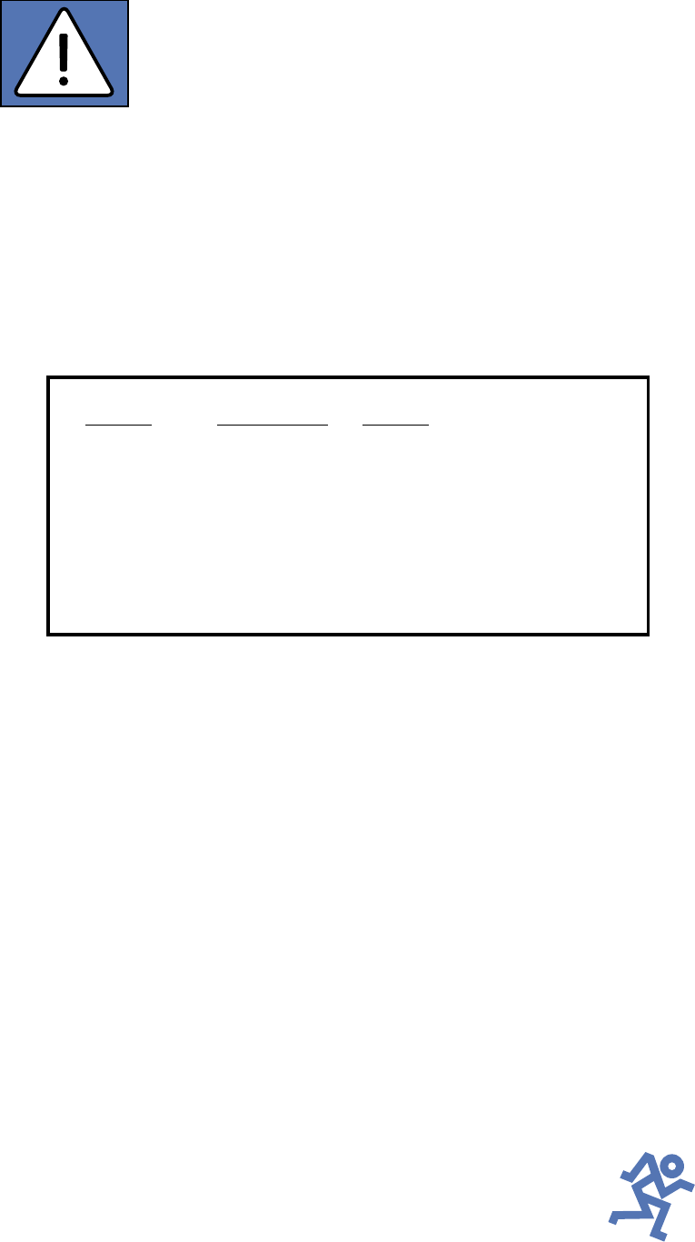
18.
Exposure to extremely high noise levels may cause permanent hearing
loss. Individuals vary considerably in susceptibility to noise-induced hearing loss,
but nearly everyone will lose some hearing if exposed to sufficiently intense
noise for a period of time. The U.S. Government’s Occupational Safety and
Health Administration (OSHA) has specified the permissible noise level exposures
shown in the following chart.
According to OSHA, any exposure in excess of these permissible limits could
result in some hearing loss. To ensure against potentially dangerous exposure to
high sound pressure levels, it is recommended that all persons exposed to equip-
ment capable of producing high sound pressure levels use hearing protectors
while the equipment is in operation. Ear plugs or protectors in the ear canals or
over the ears must be worn when operating the equipment in order to prevent a
permanent hearing loss if exposure is in excess of the limits set forth here.
SAFETY INSTRUCTIONS
1. Read Instructions — All the safety and operation instructions should be
read before this Mackie product is operated.
2. Retain Instructions — The safety and operating instructions should be kept
for future reference.
3. Heed Warnings — All warnings on this Mackie product and in these operating
instructions should be followed.
4. Follow Instructions — All operating and other instructions should be
followed.
5. Water and Moisture — This Mackie product should not be used near water
– for example, near a bathtub, washbowl, kitchen sink, laundry tub, in a wet
basement, near a swimming pool, swamp or salivating St. Bernard dog, etc.
6. Cleaning — Clean only with a dry cloth.
7. Ventilation — This Mackie product should be situated so that its
location or position does not interfere with its proper ventilation. For
example, the Component should not be situated on a bed, sofa, rug, or
similar surface that may block any ventilation openings, or placed in a
built-in installation such as a bookcase or cabinet that may impede the
flow of air through ventilation openings.
8. Heat — This Mackie product should be situated away from heat sources
such as radiators, or other devices which produce heat.
9. Power Sources — This Mackie product should be connected to a power
supply only of the type described in these operation instructions or as marked
on this Mackie product.
10 . Power Cord Protection — Power supply cords should be routed so that
they are not likely to be walked upon or pinched by items placed upon or
against them, paying particular attention to cords at plugs, convenience
receptacles, and the point where they exit this Mackie product.
11 . Object and Liquid Entry — Care should be taken so that objects do not
fall on, and liquids are not spilled into, this Mackie product.
Duration Per Day Sound Level dBA, Typical
In Hours Slow Response Example
8 90 Duo in small club
692
4 95 Subway Train
397
2 100 Very loud classical music
1.5 102
1 105 Patrice screaming at Ron about deadlines
0.5 110
0.25 or less 115 Loudest parts at a rock concert
WARNING — To reduce the risk of fire or electric shock,
do not expose this appliance to rain or moisture.
3
Lend Me Your Ears
Exposure to extremely
high noise levels may cause
permanent hearing loss.
Individuals vary
considerably in
susceptibility to noise-induced hearing loss,
but nearly everyone will lose some hearing if
exposed to sufficiently intense noise for a period
of time. The U.S. Government’s Occupational
Safety and Health Administration (OSHA) has
specified the permissible noise level exposures
shown in this chart.
®
According to OSHA, any exposure in excess
of these permissible limits could result in some
hearing loss. To ensure against potentially
dangerous exposure to high sound-pressure
levels, it is recommended that all persons
exposed to equipment capable of producing
these levels use hearing protectors while this
unit is in operation. Ear plugs or protectors in
the ear canals or over the ears must be worn
when operating this amplification system in
order to prevent a permanent hearing loss if
exposure is in excess of the limits set forth here.
Duration Per Day Sound Level dBA, Typical
In Hours Slow Response Example
8 90 Duo in small club
692
4 95 Subway Train
397
2 100 Very loud classical music
1.5 102
1 105 Lori screaming at Ron about deadlines
0.5 110
0.25 or less 115 Loudest parts at a rock concert
Part No. 820-077-00 Rev. B 2/02
©2002 Mackie Designs Inc. All Rights Reserved.

4
INTRODUCTION
406M 408M 808M 408S 808S
6 Mono Channels ✓ ✓ ✓ ✓ ✓
2 Mono/Stereo Channels ✓* ✓* ✓ ✓
Pan Controls ✓ ✓
Effects Return(s) 1 1 1 2 2
Tape Inputs ✓* ✓* ✓* ✓ ✓
Tape Outputs ✓** ✓** ✓** ✓ ✓
Mixer Line Output(s) 1 1 1 2 2
Two 250W Amplifiers ✓ ✓ ✓
Two 600W Amplifiers ✓ ✓
** Summed to Main Bus
** Mono Tape Outputs
PPM Series Features
In addition, the PPM Series boast solid design
features such as:
• Two FR Series™ (Fast Recovery)
power amplifiers
808M/808S
1200 total watts (600 watts x 2 into 2 ohms)
406M/408M/408S
500 total watts (250 watts x 2 into 2 ohms)
• Built-in compressor to prevent clipping
• Two built-in graphic equalizers for Mains
and Monitors
• Two switchable low-cut Rumble Reduction
filters for Mains and Monitors
• EMAC
TM
custom 32-bit precision digital
stereo effects processor
• Global phantom power switch
• Exclusive Break switch mutes channels 1-6
while break music is playing
• Power amp routing switch selects main out
only or main on one output and monitor on
the other output
• 3-band EQ on each channel
• Monitor and Effects send on each channel
• Balanced/unbalanced 1/4" and XLR inputs
on each channel
• 1/4" Insert jacks on channels 1-6
• 1/4" Mixer line output(s) and Monitor line
output
• 1/4" Power Amp line inputs
• Two 1/4" Speaker outputs per side
• RCA stereo Tape In and Tape Out
• Three year warranty
At Mackie, we know what it takes to be
roadworthy. After all, our mixers have traveled
all over the world under the worst of conditions,
and we’ve applied what we’ve learned to the
mechanical design of our powered mixers.
Reliability is paramount to sound reinforce-
ment. That’s why our engineers have subjected
our powered mixers to the most rigorous and
fiendish tests imaginable to fine-tune the
design and extend its limits beyond those of
ordinary mixers or amplifiers.
Our Fast Recovery (FR) amplifiers used in
the Professional Powered Mixer Series perform
better than conventional designs when present-
ed with adverse conditions such as clipping.
Conventional designs use lots of negative feed-
back to provide stability and lower distortion.
When clipping occurs, this “feedback” causes
high-frequency sticking, keeping the amplifier
“latched” in the clipping state longer than
necessary. This results in painfully audible
distortion. The Fast Recovery design eliminates
this high-frequency sticking and allows the
amplifier to remain stable when powering
highly reactive loads at high volume levels.
Please read the “Quick Start” section on
page 6. It gives an overview of the powered mixer,
and the rest of the manual explains the wealth of
features and operating instructions in more detail.
Please write your serial number here for
future reference (i.e., insurance claims, tech
support, return authorization, etc.):
Purchased at:
Date of purchase:
Thank you for choosing a Mackie Designs
PPM Series™ Powered Mixer! These powerful,
compact mixers are designed to meet the
needs of almost any small to medium-sized
club/meeting room/sanctuary/outdoor
gathering.
This chart illustrates the differences be-
tween the various models at a glance:
5
Don’t forget to visit our website at www.mackie.com
for more information about these and other Mackie products.
®
CONTENTS
Lend Me Your Ears ......................................... 3
INTRODUCTION ............................................ 4
READ THIS PAGE! .......................................... 6
QUICK START .......................................... 6
APPLICATION DIAGRAMS .......................... 7
FEATURES AND CONTROLS ........................... 14
Channel Strip Description........................ 14
INPUT LEVEL SET ............................. 14
VOLUME ........................................ 14
PAN............................................... 14
LOW EQ ......................................... 14
MID EQ .......................................... 14
HI EQ ............................................. 14
EFX Send ........................................ 15
MON Send ...................................... 15
EMAC Section Description ....................... 15
EFX DRIVE LEVEL ............................. 15
EFX CLIP......................................... 15
EFX BYPASS ................................... 15
EFX WIDE ....................................... 16
Preset Select ................................... 16
Preset Effects Descriptions ..................... 16
TIME/RATE PARAMETER .................. 18
DAMPING/DEPTH PARAMETER ......... 18
MASTER OUTPUT SECTION Description .... 18
POWER LED .................................... 18
MONITOR EQUALIZER...................... 18
MAIN EQUALIZER ............................ 18
75Hz RUMBLE REDUCTION ............... 18
EFX TO MON .................................. 19
MONITOR MASTER .......................... 19
EFX TO MAIN .................................. 19
MAIN MASTER ................................ 19
LEVEL Meters .................................. 19
PHANTOM POWER Switch ................ 19
BREAK Switch ................................. 20
POWER AMP ROUTING .................... 20
COMPRESSOR................................. 20
TAPE IN LEVEL ................................. 20
POWER switch ................................ 21
MAKING THE CONNECTIONS ............................ 21
Front Panel Connections ............................. 21
Connecting Microphones and
Line-Level Signals ...................... 21
Channel Inserts .................................... 22
EFFECTS SEND and RETURN ................... 23
EFX FOOT SWITCH ............................... 23
POWER AMP IN 1 and 2 ...................... 23
MIXER LINE OUT ................................. 24
MONITOR LINE OUT ............................ 24
TAPE IN and TAPE OUT ......................... 24
Rear Panel Connections .............................. 25
SPEAKER OUT ..................................... 25
IEC Socket .......................................... 25
GENERAL PRECAUTIONS AND CONSIDERATIONS . 26
Thermal Considerations .............................. 26
AC Power Considerations ........................... 26
APPENDIX A: Service Info ................................ 27
Warranty Service...................................... 27
Troubleshooting ........................................ 27
Repair ..................................................... 28
APPENDIX B: Some Arcane Mysteries Illuminated 29
Balanced Lines .......................................... 29
Unbalancing a Line .................................... 29
Grounding ................................................ 30
APPENDIX C: Technical Info .............................. 31
Specifications ........................................... 31
Block Diagrams ......................................... 33
NOTES ....................................................... 35

6
READ THIS PAGE!
QUICK START
We know you can’t wait to
get your new mixer set up
and working. Who has time
to read the manual? But
please, take a moment to
read through this section at least to get the
bare essentials.
The Mackie Designs powered mixers are de-
signed to set up and operate quickly and easily.
Just follow these simple directions.
Setup
Place the powered mixer in a position where
it is easy to reach the controls. All the controls
and input connection points are located on the
front panel so you can make quick adjustments
and connections onstage.
Make sure there is at least 6
inches of airspace behind
the powered mixer for ven-
tilation. There is no fan
built into the Mackie PPM
Series. It relies on convection cooling, which
means the heatsink on the back is cooled by the
natural flow of air through the heatsink fins.
Connections
1. Be sure the
POWER
switch on the back
is
OFF
before making any connections.
2. Plug a balanced microphone into one of
the
MIC
XLR (3-pin) connectors on the
front panel. Or you can connect any line-
level signal (keyboard, guitar preamp, DI
box) to the
LINE
jack using a TS or a
TRS 1/4" plug.
3. The
INSERT
jacks are used to connect an
external effects or dynamics processor
into the signal chain. See page 21 for
more info.
4. Plug the speakers (2 ohms or greater)
into the
SPEAKER OUT
jacks on the rear
panel. If you plug two speakers into a side,
each speaker must be 4 ohms or greater
to maintain a 2-ohm minimum load on
the amplifier. Use at least 18 gauge
speaker cable with 1/4" TS plugs.
Don’t use guitar cords for
speaker cables! They’re
not designed to handle
speaker-level signals and
could overheat.
Level Setting
1. Turn down the channel
MON, EFX,
INPUT LEVEL SET,
and
VOLUME
knobs
(fully counterclockwise). Set all the
EQ
controls to center, including the graphic
EQ sliders. Turn down the
MAIN MASTER
and
MONITOR MASTER
controls.
2. If your microphone is a condenser mic,
push in the
PHANTOM POWER
switch. If
you are using both condenser and dynamic
mics, don’t worry. Phantom power will not
hurt most dynamic mics. Check the micro-
phone’s user manual if you’re not sure.
3. Leave the
POWER AMP ROUTING
switch in the OUT position (
MAIN/MAIN
or
STEREO MAINS
).
4. Push the linecord securely into the IEC
connector on the rear panel, and plug it
into a 3-prong AC outlet properly config-
ured for the type of plug supplied with
your powered mixer. Turn on the
POWER
switch, which is located on the rear panel.
5. Play something into the selected input.
This could be an instrument, a singing or
speaking voice, or a line input such as a
CD player or tape recorder output. Be
sure that the volume of the input signal
is the same as it would be during normal
use. If it isn’t, you might have to readjust
these levels during the middle of the set.
6. Turn up the
INPUT LEVEL SET
control
until the LED next to it begins to blink.
7. Turn up the channel
VOLUME
control to
unity (center).
8. Slowly turn up the
MAIN MASTER
control
until you can hear the signal in the speakers.
9. Repeat steps 5, 6, and 7 for the remain-
ing channels.
10. Now you’re ready to rock and roll!
Things You Must Remember:
• Never plug amplifier outputs into
anything except speakers (unless you
have an outboard box specifically
designed to handle high-power speaker-
level signals).
• Before making connections to an exter-
nal amp or reconfiguring an amp’s
routing, turn the amp’s level (gain)
controls down, turn the power off, make
the changes, turn the power back on,
and then turn the level controls back up.
• When you shut down your equipment, turn
off any external amplifiers first. When
powering up, turn on the amplifiers last.
•Save the shipping box and packing
material! You may need them someday,
and you probably don’t want to have to
pay for them again.
7
EFX
MON
HI
12kHz
HI
12kHz
MID
2.5kHz
MON
MID
2.5kHz
MON
HI
12kHz
MID
2.5kHz
MON
HI
12kHz
MID
2.5kHz
MON
HI
12kHz
MID
2.5kHz
MON
HI
12kHz
MID
2.5kHz
MON
HI
12kHz
MID
2.5kHz
MON
HI
12kHz
MID
2.5kHz
LOW
80Hz
VOLUME CH. VOLUME CH. VOLUME CH. VOLUME CH. VOLUME CH. VOLUME CH. VOLUME CH. VOLUME CH.
1
EFX
LOW
80Hz
2
2
EFX
LOW
80Hz
3
3
EFX
LOW
80Hz
4
4
EFX
LOW
80Hz
5
5
EFX
LOW
80Hz
6
6
EFX
LOW
80Hz
78
7
EFX
LOW
80Hz
8
EFX BYPASS
EFX DRIVE
LEVEL
120
NORMAL
INPUT
LEVEL
SET
INPUT
LEVEL
SET
INPUT
LEVEL
SET
INPUT
LEVEL
SET
INPUT
LEVEL
SET
INPUT
LEVEL
SET
INPUT
LEVEL
SET
INPUT
LEVEL
SET
EFX
CLIP
PARAMETERS
100100
REVERBS
DELAYS
CHORUS
FLANGE
DAMPING
DEPTH
PHASER
TIME
RATE
NORMAL NORMAL
CUSTOM 32-BIT PRECISION
DIGITAL STEREO EFFECTS PROCESSING
EFX WIDE
MAIN EQUALIZER
30
CLIP
5
5
0
10
15
20
EFX FOOT
SWITCH
RETURN
SEND
MIXER LINE OUT
POWER
AMP 1 IN
POWER
AMP 2 IN
EFFECTS
(OVERRIDES INTERNAL EFX)
MONITOR
MAINS
TAPE IN
TAPE OUT
LEVEL
MIC
1
MIC
2
MIC
3
MIC
4
MIC
5
MIC
6
INSERT INSERT INSERT INSERT INSERT
LINELINELINELINE
LINELINE
INSERT
+15
U
OO
1K50025063 125 16K
LEVEL
30
CLIP
5
5
0
10
15
20
LEVEL
2K 4K 8K
MAIN
MASTER
EFX TO
MAIN
U
OO
+10
MASTER OUTPUT SECTION
LINE
U
+12dB
OO
LR
R
L
POWER
OUT
COMPRESSOR
2 X 250 WATTS
MONITOR EQUALIZER
15-
15+
5
10
0
5
10
-15
+15
5
10
0
5
10
15-
15+
5
10
0
5
10
-15
+15
5
10
0
5
10
1K50025063 125 16K2K 4K 8K
MONITOR
MASTER
EFX TO
MON
U
OO
+10
U
+12dB
OO
75Hz RUMBLE
REDUCTION
LEFT
RIGHT
LEFT
RIGHT
MIC
7
MIC
8
75Hz RUMBLE
REDUCTION
PHANTOM
POWER CH 1-8
BREAK
(MUTES CH 1-6)
408M
POWER AMP ROUTING
SUM
MONO
MIC/
LINE
HI-Z
SUM
MONO
MIC/
LINE
HI-Z
AMP 1
MAIN
MAIN MONITOR
AMP 2
MAIN
SM. ROOM
MD. PLATE
LG. PLATE
LG. HALL
GATED
REVERSE
CATHEDRAL
MD. HALL
SPRING
PHASER
DELAY 4
CHORUS
DELAY 3
DELAY 1
FLANGE
DELAY 2
IN
OUT
U
OO
+10
U
+15-15
U
+15-15
U
+12-12
1
U
+20dB
OO
HILOW
NORMAL
U
OO
+15
U
OO
+10
U
+15-15
U
+15-15
U
+12-12
U
+20dB
OO
HILOW
NORMAL
U
OO
+15
U
OO
+10
U
+15-15
U
+15-15
U
+12-12
U
+20dB
OO
HILOW
NORMAL
U
OO
+15
U
OO
+10
U
+15-15
U
+15-15
U
+12-12
U
+20dB
OO
HILOW
NORMAL
U
OO
+15
U
OO
+10
U
+15-15
U
+15-15
U
+12-12
U
+20dB
OO
HILOW
NORMAL
U
OO
+15
U
OO
+10
U
+15-15
U
+15-15
U
+12-12
U
+20dB
OO
HILOW
NORMAL
U
OO
+15
U
OO
+10
U
+15-15
U
+15-15
U
+12-12
U
+20dB
OO
HILOW
NORMAL
U
OO
+15
U
OO
+10
U
+15-15
U
+15-15
U
+12-12
U
+20dB
OO
HILOW
NORMAL
U
OO
+15
Vocal
Mics
Monitor
Speaker
Monitor
Speaker
Stereo Processor
Processor
Direct Box
FOH Speaker FOH Speaker
From MAIN
SPEAKER OUT
From MAIN
SPEAKER OUT
From MONITOR
SPEAKER OUT
From MONITOR
SPEAKER OUT
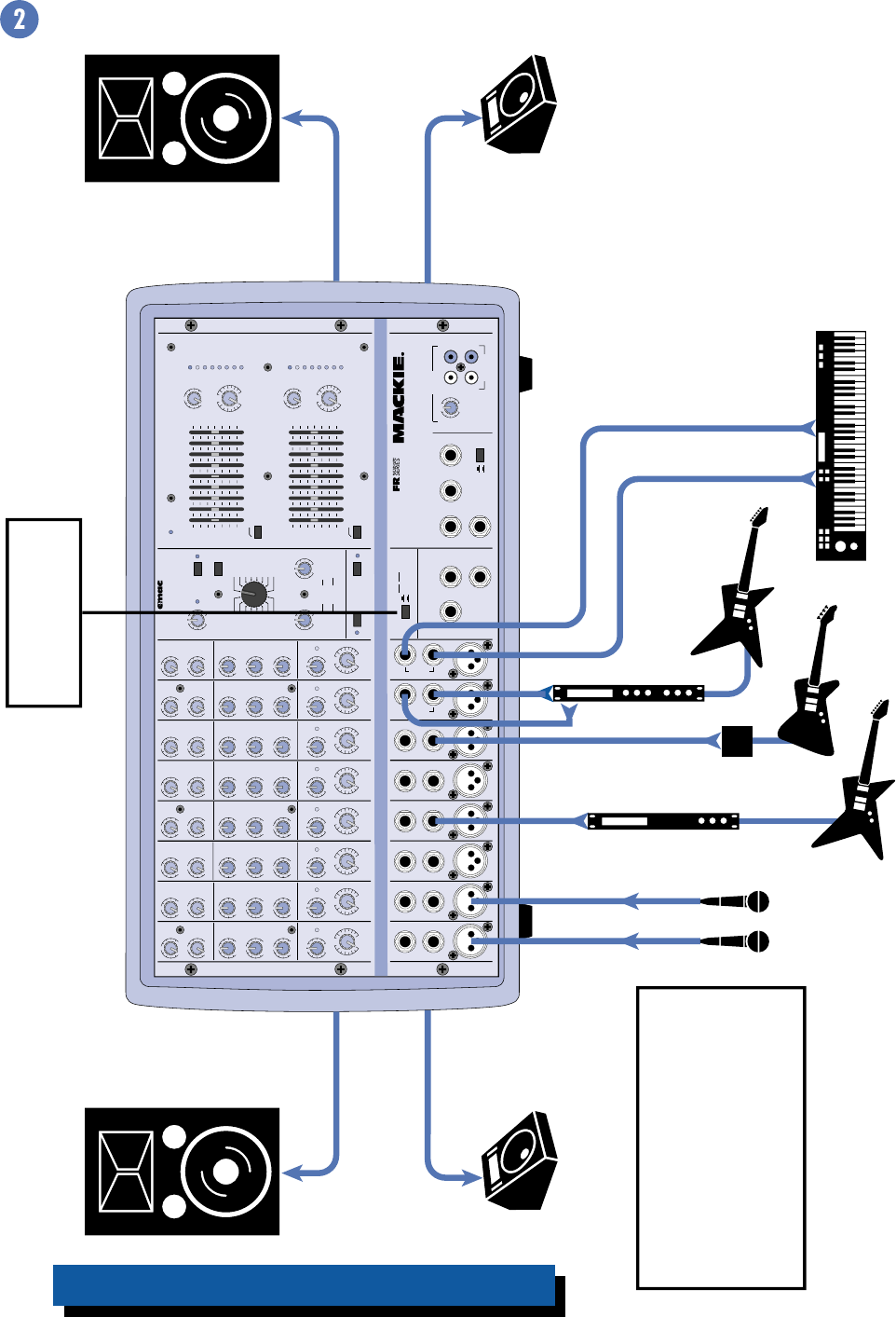
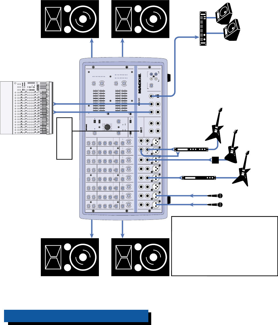
POWER AMP ROUTING
Button Pushed IN
(MAIN/MONITOR)
This is how to power the Main Front
of House (FOH) speakers and the
monitor speakers with the built-in
amplifiers.
Note: Since each amplifier is driving
two speakers in parallel, each
speaker must be 4 ohms or greater.
408M — Small Club Gig using a Mono PA System
APPLICATION DIAGRAMS
8
EFX
MON
HI
12kHz
HI
12kHz
MID
2.5kHz
MON
MID
2.5kHz
MON
HI
12kHz
MID
2.5kHz
MON
HI
12kHz
MID
2.5kHz
MON
HI
12kHz
MID
2.5kHz
MON
HI
12kHz
MID
2.5kHz
MON
HI
12kHz
MID
2.5kHz
MON
HI
12kHz
MID
2.5kHz
LOW
80Hz
PAN PAN PAN PAN PAN PAN PAN PAN
VOLUME CH. VOLUME CH. VOLUME CH. VOLUME CH. VOLUME CH. VOLUME CH. VOLUME CH. VOLUME CH.
1
EFX
LOW
80Hz
2
2
EFX
LOW
80Hz
3
3
EFX
LOW
80Hz
4
4
EFX
LOW
80Hz
5
5
EFX
LOW
80Hz
6
6
EFX
LOW
80Hz
78
7
EFX
LOW
80Hz
8
EFX BYPASS
EFX DRIVE
LEVEL
120
NORMAL
INPUT
LEVEL
SET
INPUT
LEVEL
SET
INPUT
LEVEL
SET
INPUT
LEVEL
SET
INPUT
LEVEL
SET
INPUT
LEVEL
SET
INPUT
LEVEL
SET
INPUT
LEVEL
SET
EFX
CLIP
PARAMETERS
100100
REVERBS
DELAYS
CHORUS
FLANGE
DAMPING
DEPTH
PHASER
TIME
RATE
NORMAL NORMAL
CUSTOM 32-BIT PRECISION
DIGITAL STEREO EFFECTS PROCESSING
EFX WIDE
MAIN-STEREO/MONO EQUALIZER
30
CLIP
5
5
0
10
15
20
EFX FOOT
SWITCH
RIGHT RETURNLEFT RETURN
SEND
L MIXER OUT R MIXER OUT COMPRESSOR
L POWER
AMP IN
R POWER
AMP IN
EFFECTS
(OVERRIDES INTERNAL EFX)
MONITOR
MAINS
TAPE IN
TAPE OUT
LEVEL
MIC
1
MIC
2
MIC
3
MIC
4
MIC
5
MIC
6
INSERT INSERT INSERT INSERT INSERT
LINELINELINELINE
LINELINE
INSERT
+15
U
OO
1K50025063 125 16K
LEVEL
2K 4K 8K
MAIN
MASTER
EFX TO
MAIN
U
OO
+10
MASTER OUTPUT SECTION
LINE
U
+12dB
OO
LR
R
L
POWER
OUT
MONITOR EQUALIZER
15-
15+
5
10
0
5
10
-15
+15
5
10
0
5
10
15-
15+
5
10
0
5
10
-15
+15
5
10
0
5
10
1K50025063 125 16K2K 4K 8K
MONITOR
MASTER
EFX TO
MON
U
OO
+10
U
+12dB
OO
75Hz RUMBLE
REDUCTION
RIGHT RIGHT
MIC
7
MIC
8
75Hz RUMBLE
REDUCTION
PHANTOM
POWER CH 1-8
BREAK
(MUTES CH 1-6)
408S
POWER AMP ROUTING
SM. ROOM
MD. PLATE
LG. PLATE
LG. HALL
GATED
REVERSE
CATHEDRAL
MD. HALL
SPRING
PHASER
DELAY 4
CHORUS
DELAY 3
DELAY 1
FLANGE
DELAY 2
IN
OUT
STEREO MAINS
LEFT = MAIN
RIGHT = MONITOR
2 X 250W STEREO
LEVEL
30
CLIP
5
5
0
10
15
20
LR
LEFT/MONO LEFT/MONO
STEREO
MIC/
LINE
HI-Z
STEREO
MIC/
LINE
HI-Z
U
OO
+10
U
+15-15
U
+15-15
U
+12-12
1
U
+20dB
OO
HILOW
NORMAL
U
OO
+15
U
OO
+10
U
+15-15
U
+15-15
U
+12-12
U
+20dB
OO
HILOW
NORMAL
U
OO
+15
U
OO
+10
U
+15-15
U
+15-15
U
+12-12
U
+20dB
OO
HILOW
NORMAL
U
OO
+15
U
OO
+10
U
+15-15
U
+15-15
U
+12-12
U
+20dB
OO
HILOW
NORMAL
U
OO
+15
U
OO
+10
U
+15-15
U
+15-15
U
+12-12
U
+20dB
OO
HILOW
NORMAL
U
OO
+15
U
OO
+10
U
+15-15
U
+15-15
U
+12-12
U
+20dB
OO
HILOW
NORMAL
U
OO
+15
U
OO
+10
U
+15-15
U
+15-15
U
+12-12
U
+20dB
OO
HILOW
NORMAL
U
OO
+15
U
OO
+10
U
+15-15
U
+15-15
U
+12-12
U
+20dB
OO
HILOW
NORMAL
RL RL RL RL RL RL RL RL
U
OO
+15
Vocal
Mics
Monitor
Amplifier
Monitor
Speakers
Stereo Processor
Processor
Direct Box
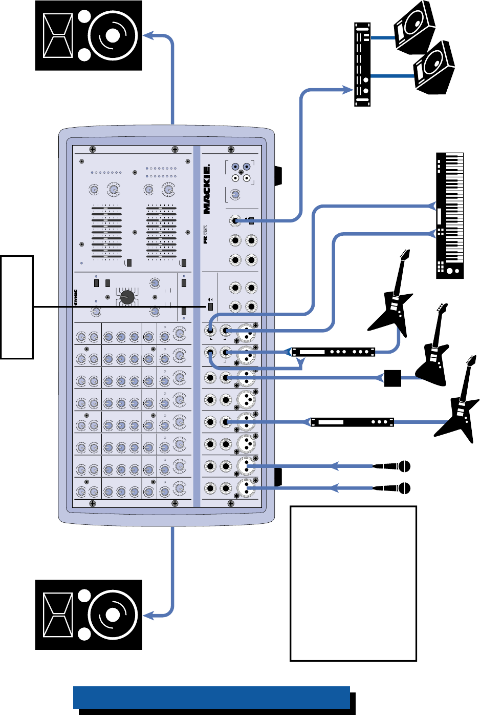
Left FOH Speaker Right FOH Speaker
From LEFT
SPEAKER OUT
From RIGHT
SPEAKER OUT
From MONITOR LINE OUT
POWER AMP ROUTING
Button OUT
This is a typical setup using both
built-in amplifiers for the main Front
of House (FOH) speakers and an
external amplifier for the monitor
speakers.
Note: If you have a 406M, 408M, or
808M, there is no stereo output
because these are mono versions.
The Main Mix bus is routed to both
internal amplifiers in these models.
408S — Small Club Gig using a Stereo PA System

9
EFX
MON
HI
12kHz
HI
12kHz
MID
2.5kHz
MON
MID
2.5kHz
MON
HI
12kHz
MID
2.5kHz
MON
HI
12kHz
MID
2.5kHz
MON
HI
12kHz
MID
2.5kHz
MON
HI
12kHz
MID
2.5kHz
MON
HI
12kHz
MID
2.5kHz
MON
HI
12kHz
MID
2.5kHz
LOW
80Hz
VOLUME CH. VOLUME CH. VOLUME CH. VOLUME CH. VOLUME CH. VOLUME CH. VOLUME CH. VOLUME CH.
1
EFX
LOW
80Hz
2
2
EFX
LOW
80Hz
3
3
EFX
LOW
80Hz
4
4
EFX
LOW
80Hz
5
5
EFX
LOW
80Hz
6
6
EFX
LOW
80Hz
78
7
EFX
LOW
80Hz
8
EFX BYPASS
EFX DRIVE
LEVEL
120
NORMAL
INPUT
LEVEL
SET
INPUT
LEVEL
SET
INPUT
LEVEL
SET
INPUT
LEVEL
SET
INPUT
LEVEL
SET
INPUT
LEVEL
SET
INPUT
LEVEL
SET
INPUT
LEVEL
SET
EFX
CLIP
PARAMETERS
100100
REVERBS
DELAYS
CHORUS
FLANGE
DAMPING
DEPTH
PHASER
TIME
RATE
NORMAL NORMAL
CUSTOM 32-BIT PRECISION
DIGITAL STEREO EFFECTS PROCESSING
EFX WIDE
MAIN EQUALIZER
30
CLIP
5
5
0
10
15
20
EFX FOOT
SWITCH
RETURN
SEND
MIXER LINE OUT
POWER
AMP 1 IN
POWER
AMP 2 IN
EFFECTS
(OVERRIDES INTERNAL EFX)
MONITOR
MAINS
TAPE IN
TAPE OUT
LEVEL
MIC
1
MIC
2
MIC
3
MIC
4
MIC
5
MIC
6
INSERT INSERT INSERT INSERT INSERT
LINELINELINELINE
LINELINE
INSERT
+15
U
OO
1K50025063 125 16K
LEVEL
30
CLIP
5
5
0
10
15
20
LEVEL
2K 4K 8K
MAIN
MASTER
EFX TO
MAIN
U
OO
+10
MASTER OUTPUT SECTION
LINE
U
+12dB
OO
LR
R
L
POWER
OUT
COMPRESSOR
MONITOR EQUALIZER
15-
15+
5
10
0
5
10
-15
+15
5
10
0
5
10
15-
15+
5
10
0
5
10
-15
+15
5
10
0
5
10
1K50025063 125 16K2K 4K 8K
MONITOR
MASTER
EFX TO
MON
U
OO
+10
U
+12dB
OO
75Hz RUMBLE
REDUCTION
LEFT
RIGHT
LEFT
RIGHT
MIC
7
MIC
8
75Hz RUMBLE
REDUCTION
PHANTOM
POWER CH 1-8
BREAK
(MUTES CH 1-6)
POWER AMP ROUTING
SUM
MONO
MIC/
LINE
HI-Z
SUM
MONO
MIC/
LINE
HI-Z
AMP 1
MAIN
MAIN MONITOR
AMP 2
MAIN
SM. ROOM
MD. PLATE
LG. PLATE
LG. HALL
GATED
REVERSE
CATHEDRAL
MD. HALL
SPRING
PHASER
DELAY 4
CHORUS
DELAY 3
DELAY 1
FLANGE
DELAY 2
IN
OUT
2 X 600 WATTS
808M
U
OO
+10
U
+15-15
U
+15-15
U
+12-12
1
U
+20dB
OO
HILOW
NORMAL
U
OO
+15
U
OO
+10
U
+15-15
U
+15-15
U
+12-12
U
+20dB
OO
HILOW
NORMAL
U
OO
+15
U
OO
+10
U
+15-15
U
+15-15
U
+12-12
U
+20dB
OO
HILOW
NORMAL
U
OO
+15
U
OO
+10
U
+15-15
U
+15-15
U
+12-12
U
+20dB
OO
HILOW
NORMAL
U
OO
+15
U
OO
+10
U
+15-15
U
+15-15
U
+12-12
U
+20dB
OO
HILOW
NORMAL
U
OO
+15
U
OO
+10
U
+15-15
U
+15-15
U
+12-12
U
+20dB
OO
HILOW
NORMAL
U
OO
+15
U
OO
+10
U
+15-15
U
+15-15
U
+12-12
U
+20dB
OO
HILOW
NORMAL
U
OO
+15
U
OO
+10
U
+15-15
U
+15-15
U
+12-12
U
+20dB
OO
HILOW
NORMAL
U
OO
+15
Vocal
Mics
CD Player
Vocal Enhancer
Effects Processor
FOH Speaker FOH Speaker
From
POWER
AMP 1
SPEAKER
OUT
From
POWER
AMP 2
SPEAKER
OUT
From MONITOR LINE OUT
POWER AMP ROUTING
Button OUT
Cassette Deck
Monitor
Amplifier
Monitor
Speakers
This system uses the higher powered
808M (600W per side) with two
speakers per side to provide more
power and coverage for a larger club,
hall, or auditorium, and an external
amplifier for the monitor speakers. It
also demonstrates how to connect a
serial processor to the channel
INSERT jack, an external (parallel)
processor using the EFFECTS SEND
and RETURN jacks, and a cassette
deck to the TAPE IN and OUT jacks.
Note: Since each amplifier is driving
two speakers in parallel, each
speaker must be 4 ohms or greater.
Note: Turn down the TAPE IN
LEVEL control (or better yet,
disconnect the TAPE IN jacks
at the mixer) when the
cassette deck is in record
mode to avoid creating a
feedback loop.
808M — Large Club or Auditorium using a Mono PA System
10
EFX
MON
HI
12kHz
HI
12kHz
MID
2.5kHz
MON
MID
2.5kHz
MON
HI
12kHz
MID
2.5kHz
MON
HI
12kHz
MID
2.5kHz
MON
HI
12kHz
MID
2.5kHz
MON
HI
12kHz
MID
2.5kHz
MON
HI
12kHz
MID
2.5kHz
MON
HI
12kHz
MID
2.5kHz
LOW
80Hz
PAN PAN PAN PAN PAN PAN PAN PAN
VOLUME CH. VOLUME CH. VOLUME CH. VOLUME CH. VOLUME CH. VOLUME CH. VOLUME CH. VOLUME CH.
1
EFX
LOW
80Hz
2
2
EFX
LOW
80Hz
3
3
EFX
LOW
80Hz
4
4
EFX
LOW
80Hz
5
5
EFX
LOW
80Hz
6
6
EFX
LOW
80Hz
78
7
EFX
LOW
80Hz
8
EFX BYPASS
EFX DRIVE
LEVEL
120
NORMAL
INPUT
LEVEL
SET
INPUT
LEVEL
SET
INPUT
LEVEL
SET
INPUT
LEVEL
SET
INPUT
LEVEL
SET
INPUT
LEVEL
SET
INPUT
LEVEL
SET
INPUT
LEVEL
SET
EFX
CLIP
PARAMETERS
100100
REVERBS
DELAYS
CHORUS
FLANGE
DAMPING
DEPTH
PHASER
TIME
RATE
NORMAL NORMAL
CUSTOM 32-BIT PRECISION
DIGITAL STEREO EFFECTS PROCESSING
EFX WIDE
MAIN-STEREO/MONO EQUALIZER
30
CLIP
5
5
0
10
15
20
EFX FOOT
SWITCH
RIGHT RETURNLEFT RETURN
SEND
L MIXER OUT R MIXER OUT COMPRESSOR
L POWER
AMP IN
R POWER
AMP IN
EFFECTS
(OVERRIDES INTERNAL EFX)
MONITOR
MAINS
TAPE IN
TAPE OUT
LEVEL
MIC
1
MIC
2
MIC
3
MIC
4
MIC
5
MIC
6
INSERT INSERT INSERT INSERT INSERT
LINELINELINELINE
LINELINE
INSERT
+15
U
OO
1K50025063 125 16K
LEVEL
2K 4K 8K
MAIN
MASTER
EFX TO
MAIN
U
OO
+10
MASTER OUTPUT SECTION
LINE
U
+12dB
OO
LR
R
L
POWER
OUT
MONITOR EQUALIZER
15-
15+
5
10
0
5
10
-15
+15
5
10
0
5
10
15-
15+
5
10
0
5
10
-15
+15
5
10
0
5
10
1K50025063 125 16K2K 4K 8K
MONITOR
MASTER
EFX TO
MON
U
OO
+10
U
+12dB
OO
75Hz RUMBLE
REDUCTION
RIGHT RIGHT
MIC
7
MIC
8
75Hz RUMBLE
REDUCTION
PHANTOM
POWER CH 1-8
BREAK
(MUTES CH 1-6)
808S
POWER AMP ROUTING
SM. ROOM
MD. PLATE
LG. PLATE
LG. HALL
GATED
REVERSE
CATHEDRAL
MD. HALL
SPRING
PHASER
DELAY 4
CHORUS
DELAY 3
DELAY 1
FLANGE
DELAY 2
IN
OUT
STEREO MAINS
LEFT = MAIN
RIGHT = MONITOR
2 X 600W STEREO
LEVEL
30
CLIP
5
5
0
10
15
20
LR
LEFT/MONO LEFT/MONO
STEREO
MIC/
LINE
HI-Z
STEREO
MIC/
LINE
HI-Z
U
OO
+10
U
+15-15
U
+15-15
U
+12-12
1
U
+20dB
OO
HILOW
NORMAL
U
OO
+15
U
OO
+10
U
+15-15
U
+15-15
U
+12-12
U
+20dB
OO
HILOW
NORMAL
U
OO
+15
U
OO
+10
U
+15-15
U
+15-15
U
+12-12
U
+20dB
OO
HILOW
NORMAL
U
OO
+15
U
OO
+10
U
+15-15
U
+15-15
U
+12-12
U
+20dB
OO
HILOW
NORMAL
U
OO
+15
U
OO
+10
U
+15-15
U
+15-15
U
+12-12
U
+20dB
OO
HILOW
NORMAL
U
OO
+15
U
OO
+10
U
+15-15
U
+15-15
U
+12-12
U
+20dB
OO
HILOW
NORMAL
U
OO
+15
U
OO
+10
U
+15-15
U
+15-15
U
+12-12
U
+20dB
OO
HILOW
NORMAL
U
OO
+15
U
OO
+10
U
+15-15
U
+15-15
U
+12-12
U
+20dB
OO
HILOW
NORMAL
RL RL RL RL RL RL RL RL
U
OO
+15
Vocal
Mics
Monitor
Amplifier
Auxiliary FOH
Amplifier
Monitor
Speakers
Stereo Processor
Processor
Direct Box
Left FOH Speakers Right FOH Speakers
From
LEFT
SPEAKER
OUT
From
RIGHT
SPEAKER
OUT
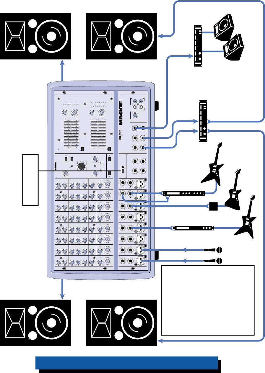
POWER AMP ROUTING
Button OUT
This shows how to connect
an auxiliary FOH amplifier,
which allows you to add
additional speakers to your
PA system and increase
the overall power.
Note: If you have a 406M,
408M, or 808M, there is no
stereo output because these
are mono versions. The Main
Mix bus is routed to both
internal amplifiers and there
is just one MIXER LINE OUT in
these models.
From MONITOR LINE OUT
From
MIXER OUT
808S with Auxiliary Amplifier to Reinforce Front of House
11
EFX
MON
HI
12kHz
HI
12kHz
MID
2.5kHz
MON
MID
2.5kHz
MON
HI
12kHz
MID
2.5kHz
MON
HI
12kHz
MID
2.5kHz
MON
HI
12kHz
MID
2.5kHz
MON
HI
12kHz
MID
2.5kHz
MON
HI
12kHz
MID
2.5kHz
MON
HI
12kHz
MID
2.5kHz
LOW
80Hz
PAN PAN PAN PAN PAN PAN PAN PAN
VOLUME CH. VOLUME CH. VOLUME CH. VOLUME CH. VOLUME CH. VOLUME CH. VOLUME CH. VOLUME CH.
1
EFX
LOW
80Hz
2
2
EFX
LOW
80Hz
3
3
EFX
LOW
80Hz
4
4
EFX
LOW
80Hz
5
5
EFX
LOW
80Hz
6
6
EFX
LOW
80Hz
78
7
EFX
LOW
80Hz
8
EFX BYPASS
EFX DRIVE
LEVEL
120
NORMAL
INPUT
LEVEL
SET
INPUT
LEVEL
SET
INPUT
LEVEL
SET
INPUT
LEVEL
SET
INPUT
LEVEL
SET
INPUT
LEVEL
SET
INPUT
LEVEL
SET
INPUT
LEVEL
SET
EFX
CLIP
PARAMETERS
100100
REVERBS
DELAYS
CHORUS
FLANGE
DAMPING
DEPTH
PHASER
TIME
RATE
NORMAL NORMAL
CUSTOM 32-BIT PRECISION
DIGITAL STEREO EFFECTS PROCESSING
EFX WIDE
MAIN-STEREO/MONO EQUALIZER
30
CLIP
5
5
0
10
15
20
EFX FOOT
SWITCH
RIGHT RETURNLEFT RETURN
SEND
L MIXER OUT R MIXER OUT COMPRESSOR
L POWER
AMP IN
R POWER
AMP IN
EFFECTS
(OVERRIDES INTERNAL EFX)
MONITOR
MAINS
TAPE IN
TAPE OUT
LEVEL
MIC
1
MIC
2
MIC
3
MIC
4
MIC
5
MIC
6
INSERT INSERT INSERT INSERT INSERT
LINELINELINELINE
LINELINE
INSERT
+15
U
OO
1K50025063 125 16K
LEVEL
2K 4K 8K
MAIN
MASTER
EFX TO
MAIN
U
OO
+10
MASTER OUTPUT SECTION
LINE
U
+12dB
OO
LR
R
L
POWER
OUT
MONITOR EQUALIZER
15-
15+
5
10
0
5
10
-15
+15
5
10
0
5
10
15-
15+
5
10
0
5
10
-15
+15
5
10
0
5
10
1K50025063 125 16K2K 4K 8K
MONITOR
MASTER
EFX TO
MON
U
OO
+10
U
+12dB
OO
75Hz RUMBLE
REDUCTION
RIGHT RIGHT
MIC
7
MIC
8
75Hz RUMBLE
REDUCTION
PHANTOM
POWER CH 1-8
BREAK
(MUTES CH 1-6)
808S
POWER AMP ROUTING
SM. ROOM
MD. PLATE
LG. PLATE
LG. HALL
GATED
REVERSE
CATHEDRAL
MD. HALL
SPRING
PHASER
DELAY 4
CHORUS
DELAY 3
DELAY 1
FLANGE
DELAY 2
IN
OUT
STEREO MAINS
LEFT = MAIN
RIGHT = MONITOR
2 X 400W STEREO
PROFESSIONAL POWERED MIXER
LEVEL
30
CLIP
5
5
0
10
15
20
LR
LEFT/MONO LEFT/MONO
STEREO
MIC/
LINE
HI-Z
STEREO
MIC/
LINE
HI-Z
U
OO
+10
U
+15-15
U
+15-15
U
+12-12
1
U
+20dB
OO
HILOW
NORMAL
U
OO
+15
U
OO
+10
U
+15-15
U
+15-15
U
+12-12
U
+20dB
OO
HILOW
NORMAL
U
OO
+15
U
OO
+10
U
+15-15
U
+15-15
U
+12-12
U
+20dB
OO
HILOW
NORMAL
U
OO
+15
U
OO
+10
U
+15-15
U
+15-15
U
+12-12
U
+20dB
OO
HILOW
NORMAL
U
OO
+15
U
OO
+10
U
+15-15
U
+15-15
U
+12-12
U
+20dB
OO
HILOW
NORMAL
U
OO
+15
U
OO
+10
U
+15-15
U
+15-15
U
+12-12
U
+20dB
OO
HILOW
NORMAL
U
OO
+15
U
OO
+10
U
+15-15
U
+15-15
U
+12-12
U
+20dB
OO
HILOW
NORMAL
U
OO
+15
U
OO
+10
U
+15-15
U
+15-15
U
+12-12
U
+20dB
OO
HILOW
NORMAL
RL RL RL RL RL RL RL RL
U
OO
+15
Vocal
Mics
Monitor
Amplifier
Subwoofer
Amplifier Monitor
Speakers
Processor
Direct Box
Left FOH Speaker Right FOH Speaker
From
LEFT
SPEAKER
OUT
From
RIGHT
SPEAKER
OUT
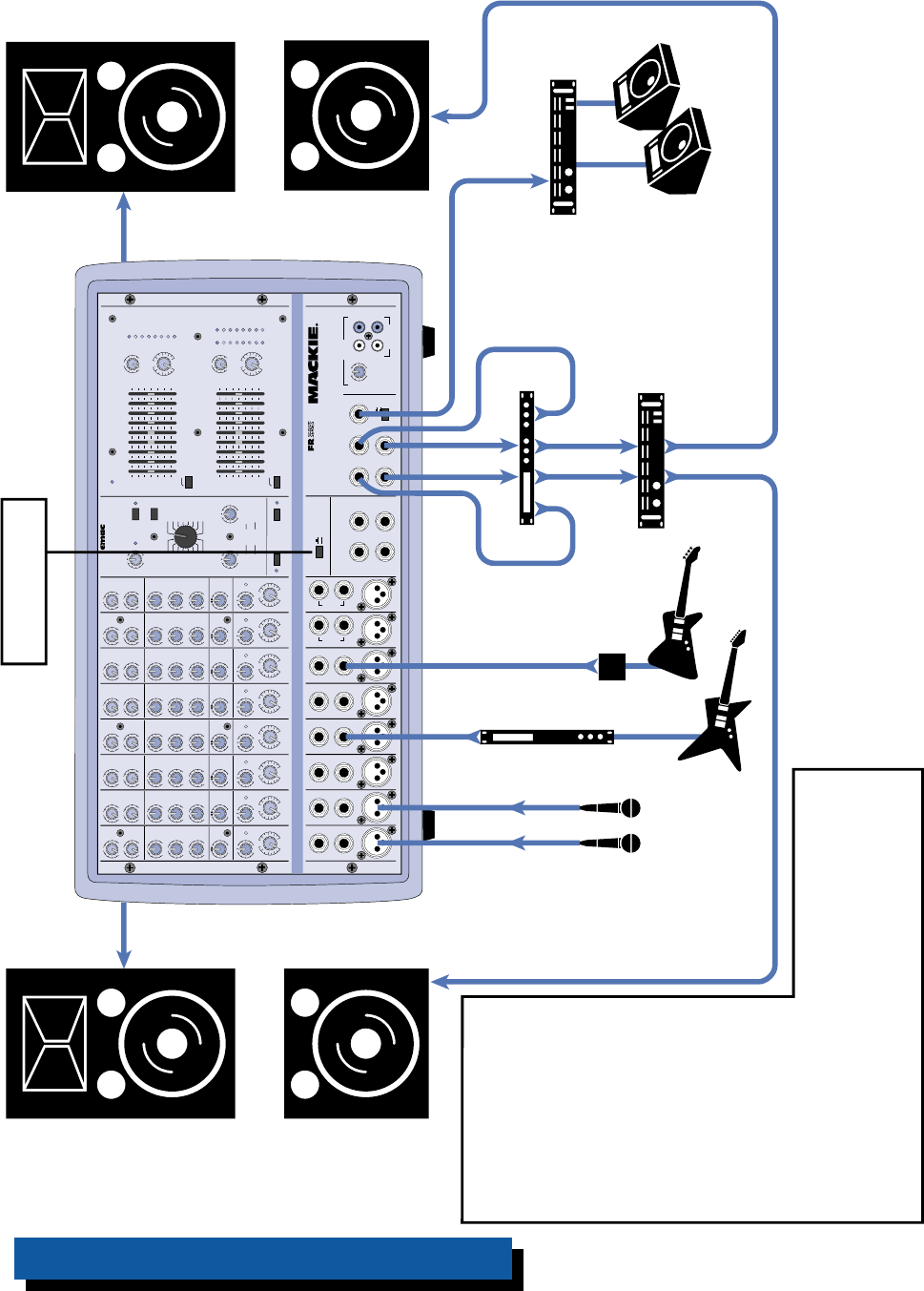
POWER AMP ROUTING
Button OUT
This shows how to use
subwoofers with the
powered mixer. The MIXER
LINE OUT is routed to an
electronic crossover, which
splits the signal into highs
and lows. The high
frequency (HF) outputs
from the crossover are
connected to the POWER
AMP IN jacks on the
powered mixer. The low
frequency (LF) outputs are
connected to an external
amplifier that powers the
subwooofers.
Note: If you have a 406M, 408M, or 808M, there is no
stereo output because these are mono versions. The Main
Mix bus is routed to both internal amplifiers and there is
just one MIXER LINE OUT in these models. Use a Y-cord to
connect the HF Out from the crossover to both POWER
AMP IN jacks on the powered mixer.
Electronic
Crossover
Left
HF
Out
Right
HF
Out
Right
LF
Out
Left
LF
Out
Subwoofer Subwoofer
From MIXER OUT
808S with Electronic Crossover and Subwoofers

12
EFX
MON
HI
12kHz
HI
12kHz
MID
2.5kHz
MON
MID
2.5kHz
MON
HI
12kHz
MID
2.5kHz
MON
HI
12kHz
MID
2.5kHz
MON
HI
12kHz
MID
2.5kHz
MON
HI
12kHz
MID
2.5kHz
MON
HI
12kHz
MID
2.5kHz
MON
HI
12kHz
MID
2.5kHz
LOW
80Hz
PAN PAN PAN PAN PAN PAN PAN PAN
VOLUME CH. VOLUME CH. VOLUME CH. VOLUME CH. VOLUME CH. VOLUME CH. VOLUME CH. VOLUME CH.
1
EFX
LOW
80Hz
2
2
EFX
LOW
80Hz
3
3
EFX
LOW
80Hz
4
4
EFX
LOW
80Hz
5
5
EFX
LOW
80Hz
6
6
EFX
LOW
80Hz
78
7
EFX
LOW
80Hz
8
EFX BYPASS
EFX DRIVE
LEVEL
120
NORMAL
INPUT
LEVEL
SET
INPUT
LEVEL
SET
INPUT
LEVEL
SET
INPUT
LEVEL
SET
INPUT
LEVEL
SET
INPUT
LEVEL
SET
INPUT
LEVEL
SET
INPUT
LEVEL
SET
EFX
CLIP
PARAMETERS
100100
REVERBS
DELAYS
CHORUS
FLANGE
DAMPING
DEPTH
PHASER
TIME
RATE
NORMAL NORMAL
CUSTOM 32-BIT PRECISION
DIGITAL STEREO EFFECTS PROCESSING
EFX WIDE
MAIN-STEREO/MONO EQUALIZER
30
CLIP
5
5
0
10
15
20
EFX FOOT
SWITCH
RIGHT RETURNLEFT RETURN
SEND
L MIXER OUT R MIXER OUT COMPRESSOR
L POWER
AMP IN
R POWER
AMP IN
EFFECTS
(OVERRIDES INTERNAL EFX)
MONITOR
MAINS
TAPE IN
TAPE OUT
LEVEL
MIC
1
MIC
2
MIC
3
MIC
4
MIC
5
MIC
6
INSERT INSERT INSERT INSERT INSERT
LINELINELINELINE
LINELINE
INSERT
+15
U
OO
1K50025063 125 16K
LEVEL
2K 4K 8K
MAIN
MASTER
EFX TO
MAIN
U
OO
+10
MASTER OUTPUT SECTION
LINE
U
+12dB
OO
LR
R
L
POWER
OUT
MONITOR EQUALIZER
15-
15+
5
10
0
5
10
-15
+15
5
10
0
5
10
15-
15+
5
10
0
5
10
-15
+15
5
10
0
5
10
1K50025063 125 16K2K 4K 8K
MONITOR
MASTER
EFX TO
MON
U
OO
+10
U
+12dB
OO
75Hz RUMBLE
REDUCTION
RIGHT RIGHT
MIC
7
MIC
8
75Hz RUMBLE
REDUCTION
PHANTOM
POWER CH 1-8
BREAK
(MUTES CH 1-6)
808S
POWER AMP ROUTING
SM. ROOM
MD. PLATE
LG. PLATE
LG. HALL
GATED
REVERSE
CATHEDRAL
MD. HALL
SPRING
PHASER
DELAY 4
CHORUS
DELAY 3
DELAY 1
FLANGE
DELAY 2
IN
OUT
STEREO MAINS
LEFT = MAIN
RIGHT = MONITOR
2 X 400W STEREO
PROFESSIONAL POWERED MIXER
LEVEL
30
CLIP
5
5
0
10
15
20
LR
LEFT/MONO LEFT/MONO
STEREO
MIC/
LINE
HI-Z
STEREO
MIC/
LINE
HI-Z
U
OO
+10
U
+15-15
U
+15-15
U
+12-12
1
U
+20dB
OO
HILOW
NORMAL
U
OO
+15
U
OO
+10
U
+15-15
U
+15-15
U
+12-12
U
+20dB
OO
HILOW
NORMAL
U
OO
+15
U
OO
+10
U
+15-15
U
+15-15
U
+12-12
U
+20dB
OO
HILOW
NORMAL
U
OO
+15
U
OO
+10
U
+15-15
U
+15-15
U
+12-12
U
+20dB
OO
HILOW
NORMAL
U
OO
+15
U
OO
+10
U
+15-15
U
+15-15
U
+12-12
U
+20dB
OO
HILOW
NORMAL
U
OO
+15
U
OO
+10
U
+15-15
U
+15-15
U
+12-12
U
+20dB
OO
HILOW
NORMAL
U
OO
+15
U
OO
+10
U
+15-15
U
+15-15
U
+12-12
U
+20dB
OO
HILOW
NORMAL
U
OO
+15
U
OO
+10
U
+15-15
U
+15-15
U
+12-12
U
+20dB
OO
HILOW
NORMAL
RL RL RL RL RL RL RL RL
U
OO
+15
Vocal
Mics
Monitor
Amplifier
Monitor
Speakers
Stereo Processor
Processor
Direct Box
Left FOH
Speakers
Submixer
(closely resembling a
Mackie CR1604-VLZ)
Right FOH
Speakers
From
LEFT
SPEAKER
OUT
From
RIGHT
SPEAKER
OUT
POWER AMP ROUTING
Button OUT
Stereo
Aux
Return
Mic
Inputs
Line
Inputs
Mon
Out Mixer
Line
Outs
Drum
Mics
Horn
Mics Monitor Send
If you need more inputs than
those provided by your PPM
Series Powered Mixer, this setup
shows how to use an external
submixer to add additional inputs
into the mix. The MIXER LINE
OUT(s) from the powered mixer
are routed to two mono or a
stereo aux return on the
submixer, where the signal is
mixed with the additional inputs
connected to the submixer. The
final, overall mix is routed back to
the POWER AMP IN jacks on the
powered mixer, which powers the
main FOH speakers.
Route the MONITOR LINE OUT on
the powered mixer to an unused
line input on the submixer. Leave
that channel's volume control
turned down, and set the
channel's monitor send control
to unity gain.
The monitor out on the submixer
is routed to an external power
amplifier, which drives the monitor
speakers.
Note: Since each amplifier is
driving two speakers in parallel,
each speaker must be 4 ohms or
greater.
From MIXER OUT
From MONITOR OUT
From MIXER OUT
From MONITOR OUT
To POWER AMP IN
808S with External Mixer using PPM Amplifiers
13
EFX
MON
HI
12kHz
HI
12kHz
MID
2.5kHz
MON
MID
2.5kHz
MON
HI
12kHz
MID
2.5kHz
MON
HI
12kHz
MID
2.5kHz
MON
HI
12kHz
MID
2.5kHz
MON
HI
12kHz
MID
2.5kHz
MON
HI
12kHz
MID
2.5kHz
MON
HI
12kHz
MID
2.5kHz
LOW
80Hz
PAN PAN PAN PAN PAN PAN PAN PAN
VOLUME CH. VOLUME CH. VOLUME CH. VOLUME CH. VOLUME CH. VOLUME CH. VOLUME CH. VOLUME CH.
1
EFX
LOW
80Hz
2
2
EFX
LOW
80Hz
3
3
EFX
LOW
80Hz
4
4
EFX
LOW
80Hz
5
5
EFX
LOW
80Hz
6
6
EFX
LOW
80Hz
78
7
EFX
LOW
80Hz
8
EFX BYPASS
EFX DRIVE
LEVEL
120
NORMAL
INPUT
LEVEL
SET
INPUT
LEVEL
SET
INPUT
LEVEL
SET
INPUT
LEVEL
SET
INPUT
LEVEL
SET
INPUT
LEVEL
SET
INPUT
LEVEL
SET
INPUT
LEVEL
SET
EFX
CLIP
PARAMETERS
100100
REVERBS
DELAYS
CHORUS
FLANGE
DAMPING
DEPTH
PHASER
TIME
RATE
NORMAL NORMAL
CUSTOM 32-BIT PRECISION
DIGITAL STEREO EFFECTS PROCESSING
EFX WIDE
MAIN-STEREO/MONO EQUALIZER
30
CLIP
5
5
0
10
15
20
EFX FOOT
SWITCH
RIGHT RETURNLEFT RETURN
SEND
L MIXER OUT R MIXER OUT COMPRESSOR
L POWER
AMP IN
R POWER
AMP IN
EFFECTS
(OVERRIDES INTERNAL EFX) MONITOR
MAINS
TAPE IN
TAPE OUT
LEVEL
MIC 1MIC 2MIC 3MIC 4MIC 5MIC 6
INSERT INSERT INSERT INSERT INSERT
LINELINELINELINE
LINELINE
INSERT
+15
U
OO
1K50025063 125 16K
LEVEL
2K 4K 8K
MAIN
MASTER
EFX TO
MAIN
U
OO
+10
MASTER OUTPUT SECTION
LINE
U
+12dB
OO
LR
R
L
POWER
OUT
MONITOR EQUALIZER
15-
15+
5
10
0
5
10
-15
+15
5
10
0
5
10
15-
15+
5
10
0
5
10
-15
+15
5
10
0
5
10
1K50025063 125 16K2K 4K 8K
MONITOR
MASTER
EFX TO
MON
U
OO
+10
U
+12dB
OO
75Hz RUMBLE
REDUCTION
RIGHT RIGHT
MIC 7MIC 8
75Hz RUMBLE
REDUCTION
PHANTOM
POWER CH 1-8
BREAK
(MUTES CH 1-6)
808S
POWER AMP ROUTING
SM. ROOM
MD. PLATE
LG. PLATE
LG. HALL
GATED
REVERSE
CATHEDRAL
MD. HALL
SPRING
PHASER
DELAY 4
CHORUS
DELAY 3
DELAY 1
FLANGE
DELAY 2
IN
OUT
STEREO MAINS
LEFT = MAIN
RIGHT = MONITOR
2 X 400W STEREO
PROFESSIONAL POWERED MIXER
LEVEL
30
CLIP
5
5
0
10
15
20
LR
LEFT/MONO LEFT/MONO
STEREO
MIC/
LINE
HI-Z
STEREO
MIC/
LINE
HI-Z
U
OO
+10
U
+15-15
U
+15-15
U
+12-12
1
U
+20dB
OO
HILOW
NORMAL
U
OO
+15
U
OO
+10
U
+15-15
U
+15-15
U
+12-12
U
+20dB
OO
HILOW
NORMAL
U
OO
+15
U
OO
+10
U
+15-15
U
+15-15
U
+12-12
U
+20dB
OO
HILOW
NORMAL
U
OO
+15
U
OO
+10
U
+15-15
U
+15-15
U
+12-12
U
+20dB
OO
HILOW
NORMAL
U
OO
+15
U
OO
+10
U
+15-15
U
+15-15
U
+12-12
U
+20dB
OO
HILOW
NORMAL
U
OO
+15
U
OO
+10
U
+15-15
U
+15-15
U
+12-12
U
+20dB
OO
HILOW
NORMAL
U
OO
+15
U
OO
+10
U
+15-15
U
+15-15
U
+12-12
U
+20dB
OO
HILOW
NORMAL
U
OO
+15
U
OO
+10
U
+15-15
U
+15-15
U
+12-12
U
+20dB
OO
HILOW
NORMAL
RL RL RL RL RL RL RL RL
U
OO
+15
Vocal
Mics
Monitor
Amplifier
Monitor
Speakers
Stereo Processor
Processor
Direct Box
Left FOH
Speakers
Right FOH
Speakers
From
LEFT
SPEAKER
OUT
From
RIGHT
SPEAKER
OUT
POWER AMP ROUTING
Button OUT
(MAIN/MAIN)
This shows how to connect
another mixer’s output to the
PPM Series POWER AMP IN
connectors.
You might use this to patch a
warm-up band’s mixer into the
PPM Series so they can use the
PPM amplifiers and PA
speakers without having to set
up a separate PA system or
change the PPM mixer settings.
Note: Unplug the warm-up
band's mixer when they're
finished to allow the main band
to come through the FOH
speakers.
Note: Since each amplifier is
driving two speakers in parallel,
each speaker must be 4 ohms
or greater.
Warm-up band's mixer
External Warm-up Band’s Mixer using 808S Amplifiers
14
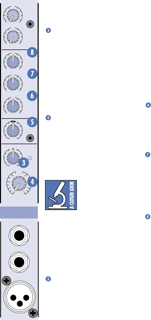
FEATURES AND CONTROLS
3-Band EQ
The PPM Series has 3-band equalization at
carefully selected points —
LOW
shelving at
80Hz,
MID
peaking at 2.5kHz, and
HI
shelving
at 12kHz. “Shelving” means that the circuitry
boosts or cuts all frequencies past the specified
frequency. For example, rotating the
LOW EQ
knob 15 dB to the right boosts bass starting at
80Hz and continuing down to the lowest note
you ever heard. “Peaking” means that only a
selected band of frequencies surrounding a
center frequency is affected by the EQ control
— the frequencies around 2.5kHz in this case.
LOW EQ
This control gives you up to 15 dB boost or
cut at 80Hz and below. The circuit is flat (no
boost or cut) at the center detent position.
This frequency represents the punch in bass
drums, bass guitar, fat synth patches, and some
really serious male singers.
MID EQ
Short for “midrange,” this knob provides
12 dB of boost or cut, centered at 2.5kHz, also
flat at the center detent. Midrange EQ is often
thought of as the most dynamic, because the
frequencies that define any particular sound
are almost always found in this range. You can
create many interesting and useful EQ changes
by turning this knob down as well as up.
HI EQ
This control gives you up to 15 dB of boost
or cut at 12kHz and above, and it is also flat at
the detent. Use it to add sizzle to cymbals, and
an overall sense of transparency or edge to key-
boards, vocals, guitar, and bacon frying. Turn it
down a little to reduce sibilance, or to hide
tape hiss.
Moderation during EQ
With EQ, you can also screw things up roy-
ally. We’ve designed a lot of boost and cut into
each equalizer circuit because we know every-
one will occasionally need that. But if you max
the EQs on every channel, you’ll get mix mush.
Equalize subtly and use the left sides of the
knobs (cut), as well as the right (boost).
EFX
MON
HI
12kHz
MID
2.5kHz
LOW
80Hz
PAN
VOLUME CH.
1
INPUT
LEVEL
SET
MIC
1
INSERT
LINE
U
OO
+10
U
+15-15
U
+15-15
U
+12-12
1
U
+20dB
OO
HILOW
NORMAL
U
OO
+15
RL
Stereo Version
Channel Strip
Channel Strip Description
INPUT LEVEL SET
If you haven’t done so already, please read
the “Level-Setting” procedure on page 6.
The
INPUT LEVEL SET
control adjusts the
input sensitivity of the mic and line inputs (on
channels 7 & 8 it affects only the mic input).
This allows signals from the outside world to be
adjusted to optimal internal operating levels.
To correctly adjust the
INPUT LEVEL SET
control, apply a signal to the channel and turn
up the
INPUT LEVEL SET
control until the LED
next to it just begins to blink. This provides the
best signal-to-noise ratio for the channel.
VOLUME
The rotary
VOLUME
knob controls the
channel’s level…from off to unity gain at the
center detent, on up to +20 dB of additional
gain when turned all the way up. The
VOLUME
control is equivalent to a channel fader.
These are mono controls except on chan-
nels 7 and 8 of the 408S and 808S models,
which use stereo controls.
Unity gain means there is no
change in signal level. In
other words, the signal enter-
ing the control is the same
volume (or in this case, the
same voltage level) as the signal leaving the
control. Once you have adjusted the
INPUT
LEVEL SET
controls on all the channels, you
can set the remaining controls to their unity
(
U
) positions and your signals will travel
through the mixer at optimal levels. What’s
more, all the labels on our level controls are in
decibels (dB), so you’ll know what you’re doing
level-wise if you choose to change a control’s
settings.
PAN
This control appears on the stereo models
(408S and 808S).
PAN
adjusts the amount of
channel signal sent to the left versus the right
outputs. On the mono channels 1-6 these con-
trols act as true pan pots. On the stereo
channels 7 and 8, the
PAN
knob acts like the
balance control on your home stereo.
15
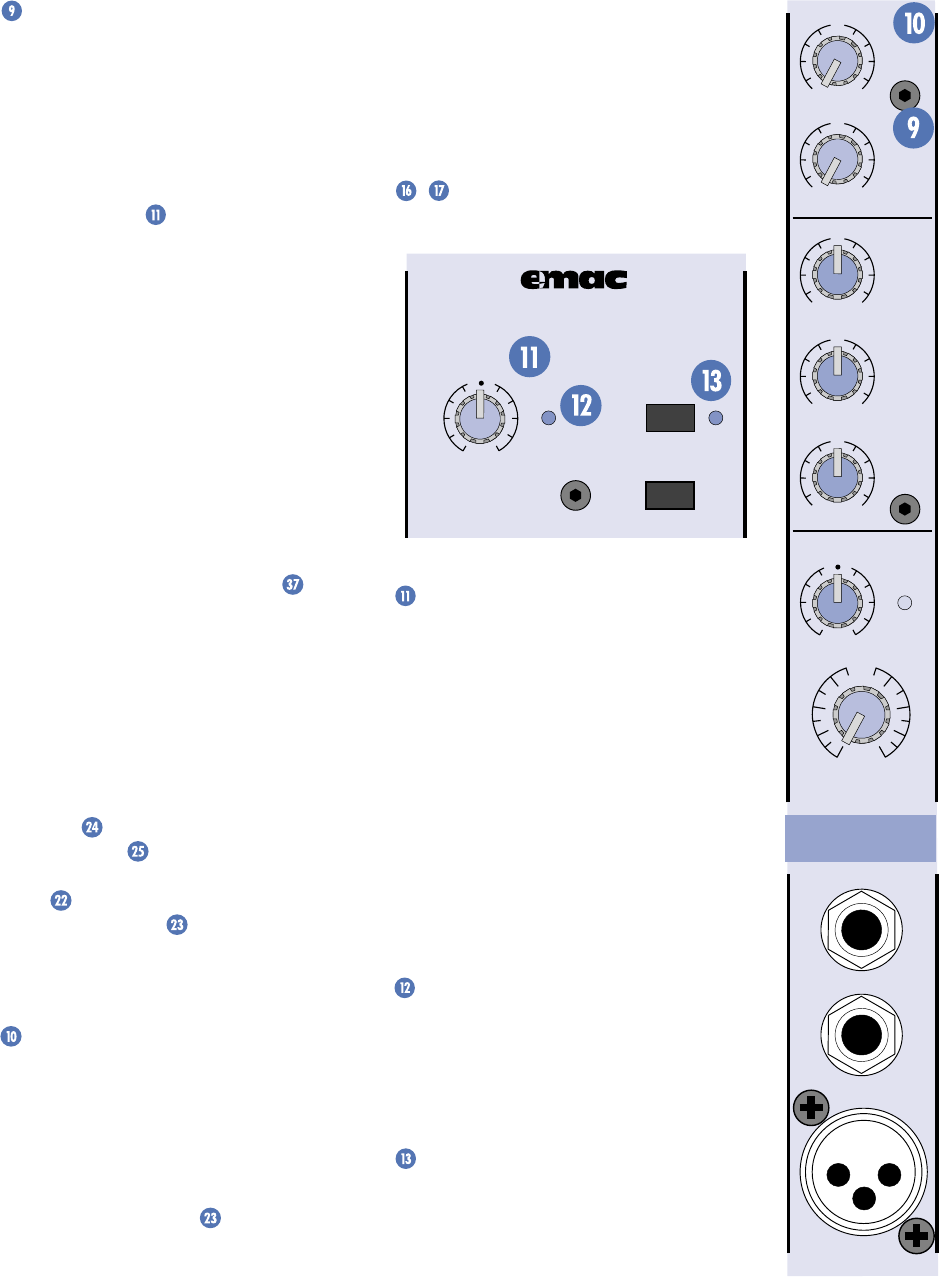
EFX Send
This taps the channel’s signal out to either
the internal
EMAC
Digital Stereo Effects
Processor or to an external device via the
EFFECTS SEND
jack for parallel effects pro-
cessing. Each channel’s effects send signal is
controlled by the channel’s
EFX
knob, and the
overall effects send level is controlled by the
EFX DRIVE LEVEL
knob (located in the
EMAC
section).
The effects send signal is post-EQ and post-
VOLUME
, so these controls affect the signal
going to the effects processor, be it internal or
external.
Each
EFX
send control ranges from off
through unity (the center detent position) on
up to +10 dB of extra gain (when turned fully
clockwise). Chances are you’ll never need this
much extra gain, but it’s nice to know it’s there
if you do.
Normally the effects send signal is routed
to the internal
EMAC
Digital Stereo Effects
Processor (more on
EMAC
coming up). However,
if you plug into the
EFFECTS SEND
jack
(located just below the
EMAC
section) you
can send the effects signal to an external
effects device. You can return the signal from
the external effects device by plugging its
output into the
EFFECTS RETURN
jack(s)
just below the
SEND
jack. This disconnects
the
EMAC
from the internal effects bus.
You mix the amount of effects you want
returned to the main mix by adjusting the
EFX
TO MAIN
control located just above the
MAIN MASTER
. You can also add effects to
the monitor mix by adjusting the
EFX TO
MON
control located just above the
MONITOR MASTER
.
Note: See “Effects Send and Return” on
page 22 to see how to use
EMAC
and an
external effects processor at the same time.
MON Send
This taps the channel’s signal out to an
external amplifier, which powers your moni-
tor speakers, via the
MONITOR LINE OUT
jack. Each channel’s monitor send signal is
controlled by the channel’s
MON
knob, and
the overall monitor send level is controlled by
the
MONITOR MASTER
control.
The monitor send signal is pre-EQ and pre-
VOLUME
, so if you adjust these controls they will
affect only the main mix and not the monitor mix.
Each
MON
send control ranges from off
through unity (the center detent position) on
up to +15 dB of extra gain.
EMAC Section Description
EMAC™ stands for Extended Multiply and
Accumulate, which is a proprietary 32-bit digital
stereo processor developed by our Digital
Engineering Group. It provides 16 preset digital
effects algorithms for you to select. In addition
to the presets, there are two parameter controls
/ you can adjust to change the sound and
make it unique for your particular application.
EFX BYPASS
EFX DRIVE
LEVEL
120
NORMAL
EFX
CLIP
CUSTOM 32-BIT PRECISION
DIGITAL STEREO EFFECTS PROCESSING
EFX WIDE
EFX DRIVE LEVEL
This controls the signal level being sent to
the input of the
EMAC
module (and to the
EFX
SEND
jack). Use the
EFX
controls on the indi-
vidual channels to adjust the amount of each
channel’s signal you want to go to the
EMAC
.
Leave the
EFX DRIVE LEVEL
set at the
NOR-
MAL
position. If you find that you’re not getting
enough of the effect in the main mix, make
sure that the
EFX TO MAIN
control is turned
up at least to unity (the center detent posi-
tion). It’s okay to turn up the
EFX DRIVE
LEVEL
some more if you need to. Just make
sure the
EFX CLIP
LED never lights more than
occasionally. Read on to find out why.
EFX CLIP
This indicates when the
EMAC
is 6 dB
below clipping. This LED should only light
occasionally. If it blinks frequently, you should
turn down the
EFX DRIVE LEVEL
a little.
Digital clipping is not pleasant to behold.
EFX BYPASS
Pushing in this button causes the
EFX
BYPASS
indicator to light and mutes the
effects signal. It affects both the internal
EMAC
effects and any external effects
processor you may have connected to the
EFFECTS RETURN
jack.
EFX
MON
HI
12kHz
MID
2.5kHz
LOW
80Hz
VOLUME CH.
1
INPUT
LEVEL
SET
MIC
1
INSERT
LINE
U
OO
+10
U
+15-15
U
+15-15
U
+12-12
1
U
+20dB
OO
HILOW
NORMAL
U
OO
+15
Mono Version
Channel Strip
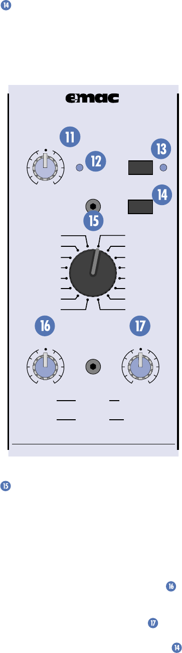
16
EFX WIDE
Depending on the effect selected, this
switch adds more width or depth to the effect.
Note that it doesn’t work with the
DELAY
and
PHASER
effects because they are monophonic.
REVERSE
: Standard reverse reverb, simulat-
ing a tail-first effect increasing to the original
note. Decay range adjustable from 35ms to
515ms. No pre-delay.
GATED
: Standard gated reverb where the
reverb tail is cut off sharply after preset decay
length. Decay range adjustable from 35ms to
515ms. No pre-delay.
CATHEDRAL
: Dense, smooth reverb with
very long tail, long pre-delay, and late reflec-
tions. Tails are very warm with some additional
high-end reflections imitating the stone walls
of a cathedral. A very dramatic effect that
works well with wind instruments such as
flute, slow finger picking on acoustic guitar,
and quiet vocal group harmony and choirs. Also
works well with keyboards and drums using
short decay. Decay range adjustable from 2 sec-
onds to 10 seconds. Pre-delay set at 75ms.
LG. HALL
: Dense, smooth reverb with long
tail, long pre-delay, and some early reflections.
Tails are warm with more apparent high end.
Works well with vocals and electric and acous-
tic guitar. Decay range adjustable from 1
second to 5 seconds. Pre-delay set at 75ms.
MD. HALL
: Dense, smooth reverb with nor-
mal tail, normal pre-delay, and increased early
reflections. Tails are warm with more apparent
high end. Works well with vocals and electric
and acoustic guitar. Decay range adjustable
from 750ms to 2.5 seconds. Pre-delay set at
65ms.
LG. PLATE
: Good early reflections and no
pre-delay. Tails are normal and warm with
strong high end for increased presence. Perfect
for vocals and snare. Decay range adjustable
from 1 second to 5 seconds. No pre-delay.
MD. PLATE
: Good early reflections and no
pre-delay. Tails are short and warm with strong
high end for increased presence. Perfect for
tight vocals and snare. Decay range adjustable
from 750ms to 2.5 seconds. No pre-delay.
SM. ROOM
: Reverb featuring very fast and
scattered early reflections with a short pre-
delay. Tails are very short and warm with
normal high-end imitating absorbent wall
materials and audience. Good for tight vocal
effects. Decay range adjustable from 250ms to
1 second. Pre-delay set at 30ms.
SPRING
: Mimics the vintage 60's-style wet
spring reverb effect. Tails are normal with
strong high end and a slight waver imitating
the slow flutter of the mechanical spring sys-
tem. Very good with acoustic guitar. Decay
range adjustable from 1 second to 5 seconds.
No pre-delay.
EFX BYPASS
EFX DRIVE
LEVEL
120
NORMAL
EFX
CLIP
PARAMETERS
100100
REVERBS
DELAYS
CHORUS
FLANGE
DAMPING
DEPTH
PHASER
TIME
RATE
NORMAL NORMAL
CUSTOM 32-BIT PRECISION
DIGITAL STEREO EFFECTS PROCESSING
EFX WIDE
SM. ROOM
MD. PLATE
LG. PLATE
LG. HALL
GATED
REVERSE
CATHEDRAL
MD. HALL
SPRING
PHASER
DELAY 4
CHORUS
DELAY 3
DELAY 1
FLANGE
DELAY 2
Preset Select
Rotate this detented switch to select the
preset effect you want to use.
Preset Effects Descriptions
Reverbs
The reverbs are designed to provide a wide
variety of reverb sounds for vocal and instrument
applications. The
TIME/RATE PARAMETER
controls the length of the tail, with the shortest
tail at the
0
position and the longest tail at
10
.
The
DAMPING/DEPTH PARAMETER
controls the damping, with the darkest tone at
0
and the brightest tone at
10
. The
EFX WIDE
switch is very effective at increasing the stereo
image of the reverb effect in the stereo versions
and enhancing reverb density in mono versions.

17
Delays
There are four delays available. Delay 1 has
one repeat after the original note. Delay 2 has
two repeats, Delay 3 has three, and Delay 4 has
four. The
TIME/RATE PARAMETER
controls the
time between repeats, with the fastest repeats
at the
0
position and the slowest repeats at
10
.
The
DAMPING/DEPTH PARAMETER
controls
the damping, with the darkest tone at
0
and
the brightest tone at
10
. For an analog tape
delay sound, use a darker setting so that each
subsequent repeat is darker than the prior one.
For a crisp digital delay sound, use a brighter
setting so the tone retains its high end on each
subsequent repeat. Since the delay effect is not
stereo, it is not affected by the
EFX WIDE
switch.
DELAY 1
: One repeat. Works best for
slapback delay used in country and swing gui-
tar, and for rockabilly and some country vocals.
Delay range adjustable from 5ms to 524ms.
DELAY 2
: Two repeats. Provides a fuller,
more dramatic effect for rock and gospel vocals,
acoustic guitar, and wind instruments such as
flute. Especially effective for some finger-picking
styles. Delay range adjustable from 5ms to 524ms.
DELAY 3
: Three repeats. An excellent delay
for slow, bluesy vocals and melodic flute music.
This delay usually works best when the chan-
nel EFX send is set at less than halfway. Delay
range adjustable from 5ms to 524ms.
DELAY 4
: Four repeats. This is for very dra-
matic delay effects, particularly for enhancing
long vocal notes and dramatic instrumental
note-chopping effects. Be sure to set the chan-
nel EFX send at about halfway. Delay range
adjustable from 5ms to 524ms.
Modulation Effects
These include Chorus, Flange and Phaser,
and are generally used for enhancement of
instrumental music. However, Chorus adds a
dramatic effect to vocals as well. The
EFX WIDE
switch is very effective at dramatically increas-
ing the strength and thickness of a modulation
effect. For example, using the
EFX WIDE
on
Chorus mimics a multi-voiced chorus effect.
The
TIME/RATE PARAMETER
controls the
effect Rate, which is the speed of the sweeping
effect. Fully counter-clockwise produces the
slowest sweeps and fully clockwise produces
the fastest.
DAMPING/DEPTH PARAMETER
controls the effect depth, which is the strength
of the sweeping effect. Fully counter-clockwise
produces the lightest sweeping effect and fully
clockwise produces the thickest.
CHORUS
: Provides a soft, ethereal sweeping
effect. Perfect for enhancement of electric and
acoustic guitar and bass. Also adds a dramatic
effect to vocals, particularly group harmonies
and choirs. The channel
EFX
send should be set
halfway or higher. Rate adjustable from 0.5Hz to
30Hz. Depth adjustable from 0% to 100%.
FLANGE
: Creates a strong sweeping effect,
particularly effective on rock electric guitar, lead
and rhythm. The channel
EFX
send should be set
halfway or higher. Rate adjustable from 0.5Hz to
20Hz. Depth adjustable from 0% to 100%.
PHASER
: This effect is perfect for enhanc-
ing strummed acoustic guitar or electric guitar
power chords. The
PHASER
effectively dupli-
cates the popular 70's phase shift effect used
for guitar. Rate adjustable from 0.5Hz to 35Hz.
Depth adjustable from 50% to 100%.
Name Parameters Typical Applications
Reverbs Decay/Pre-delay
REVERSE 35ms-515ms/none Special effects on instruments or drums
GATED 35ms-515ms/none Special effects on instruments or drums
CATHEDRAL 2sec-10sec/75ms Wind instruments; acoustic guitar; choir
LG. HALL 1sec-5sec/75ms Vocals; electric and acoustic guitar
MD. HALL 750ms-2.5sec/65ms Vocals; electric and acoustic guitar
LG. PLATE 1sec-5sec/none Vocals; snare
MD. PLATE 750ms-2.5sec/none Tight vocals; snare
SM. ROOM 250ms-1sec/30ms Tight vocals
SPRING 1sec-5sec/none Acoustic guitar
Delays Delay/No. of Repeats
DELAY 1 5ms-524ms/1 Country, swing guitar; rockabilly vocals
DELAY 2 5ms-524ms/2 Rock, gospel vocals; acoustic guitar; wind instruments
DELAY 3 5ms-524ms/3 Slow, bluesy vocals; melodic flute
DELAY 4 5ms-524ms/4 Long vocal notes
Chorus/Flange/Phase Modulation/Depth
CHORUS 0.5Hz-30Hz/0%-100% Electric, acoustic guitars; bass; choir
FLANGE 0.5Hz-20Hz/0%-100% Rock electric guitar
PHASER 0.5Hz-35Hz/50%-100% Strummed acoustic guitar, electric guitar power chords
EMAC SELECTIONS

18
TIME/RATE PARAMETER
If you have a reverb effect selected, this
control adjusts how long the reverberation
lasts, with 0 being a short reverb time and 10
being the longest.
If you have a delay effect selected, this
adjusts the amount of time between the origi-
nal signal and the delayed signal, with
0
being
a short delay time and
10
being the longest
delay time.
If you have a chorus, flange, or phaser effect
selected, this control adjusts the rate or speed
of the modulation of the effect.
DAMPING/DEPTH PARAMETER
If you have a reverb or delay effect selected,
this control adjusts how fast the higher frequen-
cies roll off in the reverberation or delay, with
0
having no roll off and
10
having the most roll off.
If you have a chorus, flange, or phaser effect
selected, this control adjusts the depth of the
modulation of the effect.
MAIN EQUALIZER
The
MAIN EQUALIZER
is used to shape
the overall frequency response for the main
speakers. The equalizer is the last thing in the
chain prior to the signal being routed to the
power amplifiers and the
MIXER LINE OUT
.
How to Adjust the Graphic Equalizers:
Note: These instructions are written on the
top of the PPM Series cabinet, but we’ll repeat
them here because they are so important.
Reducing Feedback (Do monitor first)
1. Set the
MIC
channels to working volume
levels (see “Level Setting” on page 6).
2. Set the Graphic EQ sliders to zero (center).
3. Slowly turn up the
MAIN MASTER
volume until feedback just begins to
occur. BE CAREFUL! Feedback can occur
quickly and become very LOUD, very fast.
4. Cut the appropriate slider until feedback
stops.
Suggestions for Better Sound
1. For better vocal sound, set the
125, 250,
and
16K
sliders to +5.
Note: Make sure the singer is within 3 to
6 inches of the microphone. No amount
of EQ can save a vocal when the singer is
too far away from the microphone.
2. For more presence, set the
4K
and
8K
sliders to +5.
3. To warm up the overall sound, set the
2K
slider to –5.
4. Use the
RUMBLE REDUCTION
switch to
reduce the noise floor.
5. REMEMBER, LESS IS BETTER.
75Hz RUMBLE REDUCTION
There are two of these switches; one for the
monitor output and one for the main output.
Pushing in this switch places a low-cut filter
into the circuit path, rolling off the frequencies
below 75Hz.
Use the
RUMBLE REDUCTION
switch on
the main output to reduce stage rumble (low-
frequency noise from footsteps picked up by
microphones on stage) and microphone-
handling noise. Use the
RUMBLE REDUCTION
switch on the monitor output to reduce the
muddiness caused by the lows feeding back into
the main output through the stage microphones.
Note: This filter is separate from the graphic
equalizer. The main
RUMBLE REDUCTION
switch affects only channels 1-6 and not the
stereo channels 7 & 8,
EFX TO MAIN
, or
TAPE
IN
. The monitor
RUMBLE REDUCTION
switch
does affect the
EFX TO MON
signal.
PARAMETERS
100100
REVERBS
DELAYS
CHORUS
FLANGE
DAMPING
DEPTH
PHASER
TIME
RATE
NORMAL NORMAL
MASTER OUTPUT SECTION Description
POWER LED
This indicator lights up whenever the
POWER
switch is turned on and the PPM Series
is plugged into a live outlet, just to let you
know you’re ready for action.
MONITOR EQUALIZER
The
MONITOR EQUALIZER
is used to
shape the overall frequency response for the
monitor speakers on stage. This is called a
graphic equalizer because the position of the
sliders provides a graphic display of the
frequency response at its output. The equalizer
is the last thing in the signal chain prior to
being routed to the
MONITOR LINE OUT
(and the power amplifier if the
POWER AMP
ROUTING
switch is pushed in).
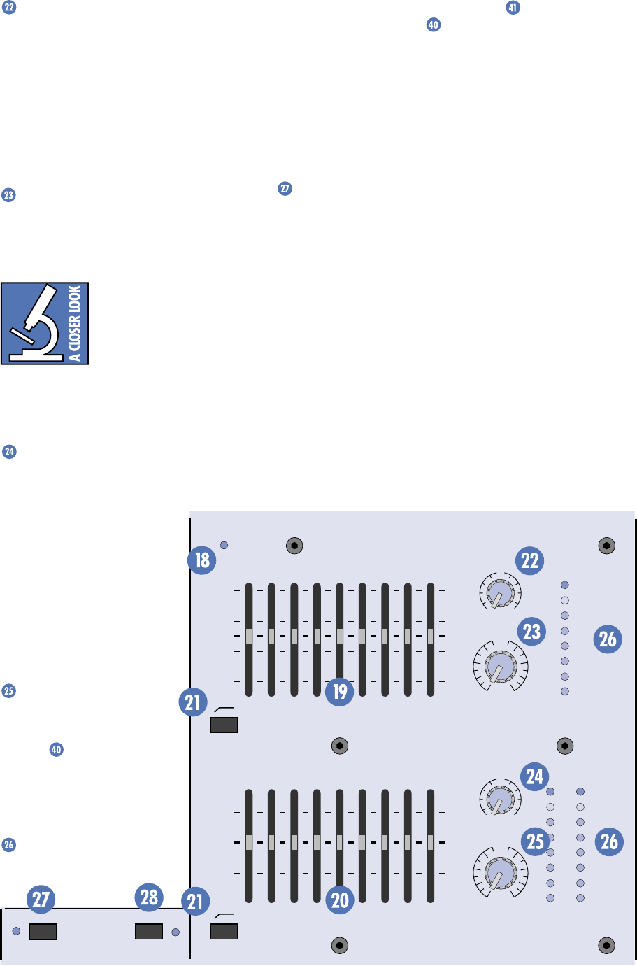
19
EFX TO MON
Use this control to add the
EMAC
internal
effects (or external effects, if connected) to the
monitor mix. The effects signal is added to the
monitor signal path just prior to the
RUMBLE
REDUCTION
switch and the
MONITOR
MASTER
control.
The
EFX TO MON
control ranges from off
through unity (the center detent position) on
up to +10 dB of extra gain.
MONITOR MASTER
This controls the overall signal level at the
MONITOR LINE OUT
. The control ranges from
off through unity on up to +12 dB of extra gain.
Turning up the
MONITOR
MASTER
too much can
cause feedback. To reduce
the possibility of feedback,
try to position the micro-
phones so they are pointing away from the
stage monitors. This will minimize the amount
of monitor signal that is picked up by the
microphones.
EFX TO MAIN
Use this control to add the
EMAC
internal
effects (or external effects, if connected) to
the main mix. The effects
signal is added to the main
signal path just after the
RUMBLE REDUCTION
switch
and just prior to the
MAIN
MASTER
control.
The
EFX TO MAIN
control
ranges from off through unity
(the center detent position) on
up to +10 dB of extra gain.
MAIN MASTER
This controls the overall sig-
nal level at the
MIXER LINE
OUT
(s) and at the input to
the power amplifiers. The con-
trol ranges from off through
unity on up to +12 dB of extra
gain.
LEVEL Meters
These 8-segment LED meters
indicate the
signal level at the
MONITOR LINE OUT
and the
MIXER LINE OUT
. To attain the
best signal-to-noise ratio while still maintain-
ing adequate headroom, set the
MONITOR
MASTER
and
MAIN MASTER
controls so the
0 dB indicator on the
LEVEL
meters blinks
frequently. It’s okay for the +5 dB indicator to
blink occasionally, but avoid allowing the
CLIP
indicator to light. Clipping occurs at a +20 dBu
output level.
PHANTOM POWER Switch
Push in this switch to provide phantom
power to the XLR
MIC
input connectors. All of
the XLR mic inputs are capable of providing
phantom power. Phantom power is required
to operate most condenser microphones
(some condenser microphones are battery-
powered). The PPM Series provide +15V DC
phantom powering on pins 2 and 3 of the XLR
connectors.
If you are using condenser microphones, or
any mic that requires phantom power, engage
the
PHANTOM POWER
switch (located just
below the
EMAC
section). If you have dynamic,
ribbon, or tube mics that do not require phan-
tom power, leave the
PHANTOM POWER
switch out. If you are using both condenser and
dynamic mics, don’t worry. Phantom power will
MAIN-STEREO/MONO EQUALIZER
30
CLIP
5
5
0
10
15
20
1K50025063 125 16K
LEVEL
2K 4K 8K
MAIN
MASTER
EFX TO
MAIN
U
OO
+10
MASTER OUTPUT SECTION
U
+12dB
OO
POWER
MONITOR EQUALIZER
15-
15+
5
10
0
5
10
-15
+15
5
10
0
5
10
15-
15+
5
10
0
5
10
-15
+15
5
10
0
5
10
1K50025063 125 16K2K 4K 8K
MONITOR
MASTER
EFX TO
MON
U
OO
+10
U
+12dB
OO
75Hz RUMBLE
REDUCTION
75Hz RUMBLE
REDUCTION
PHANTOM
POWER CH 1-8
BREAK
(MUTES CH 1-6)
LEVEL
30
CLIP
5
5
0
10
15
20
LR
Stereo Version Master Output Section
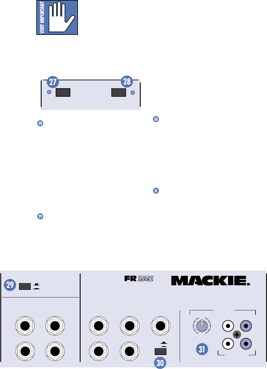
20
not hurt most dynamic mics. Check the micro-
phone’s user manual if you’re not sure.
Caution: Turn all output
levels down before operat-
ing this switch to avoid the
possibility of a “pop” in
your speakers.
Connecting a line-level input to an XLR in-
put connector with the phantom power
switched on could damage the output of the
source device. We recommend using the 1/4"
jacks for line-level inputs.
PHANTOM
POWER CH 1-8
BREAK
(MUTES CH 1-6)
BREAK Switch
As in “take a break.” Push this switch in dur-
ing your breaks and the mono channels (1-6),
monitor send, and effects send are muted so you
don’t run the danger of something going haywire
during your break, like having your system start
feeding back or having some would-be poet jump
up on stage and start reciting his latest epic.
This switch doesn’t affect the
TAPE IN
or
the stereo channels (7&8) so you can go ahead
and run your cassette or CD player while you
are on break.
POWER AMP ROUTING
This handy switch provides the flexibility to
use the internal power amplifiers to power
both the main and monitor outputs, or to
power two main speakers with the internal
amplifiers and use a separate power amplifier
to power the monitor speakers.
When the switch is in the OUT position, the
main mix is routed to the inputs of both
amplifiers. For the mono versions (406M,
408M, 808M), the same signal is routed to the
inputs of both amplifiers. You must have another
amplifier to power your monitor speakers.
When the switch is pushed IN, the main mix
is routed to the input of the
MAIN
power amp,
and the monitor mix is routed to the input of
the
MONITOR
power amp. You can still con-
nect up to two speakers to each amplifier
output, since there are two parallel
SPEAKER
OUTPUT
jacks for each amplifier on the back
panel. Just remember to maintain a 2 ohm
load or greater for each amplifier.
Note: On the stereo versions (408S, 808S),
the left and right signals are summed together
just prior to the
MAIN
power amp input when
the
POWER AMP ROUTING
switch is pushed in.
COMPRESSOR
Pushing this switch in activates a circuit at
the input to the power amplifiers that senses
the signal level and reduces the possibility of
driving the amplifier into clipping. Clipping
creates distortion that not only sounds bad, but
can actually damage your loudspeakers. We
recommend that you leave this switch pushed
in (unless you hate your speakers).
TAPE IN LEVEL
You can connect a tape deck or CD player
to the PPM Series and play back prerecorded
music during your breaks. The tape signal is
added to the main signal path just after the
RUMBLE REDUCTION
switch and just prior to
the
MAIN MASTER
control. This is a stereo
control, but for the mono versions (406M, 408M,
808M), the left and right inputs are summed.
EFX FOOT
SWITCH
RIGHT RETURNLEFT RETURN
SEND
L MIXER OUT R MIXER OUT COMPRESSOR
L POWER
AMP IN
R POWER
AMP IN
EFFECTS
(OVERRIDES INTERNAL EFX) MONITOR
MAINS
TAPE IN
TAPE OUT
LEVEL
+15
U
OO
LINE
LR
R
L
OUT
408S
POWER AMP ROUTING
IN
OUT
STEREO MAINS
LEFT = MAIN
RIGHT = MONITOR
2 X 250W STEREO
Stereo Version Connector Section
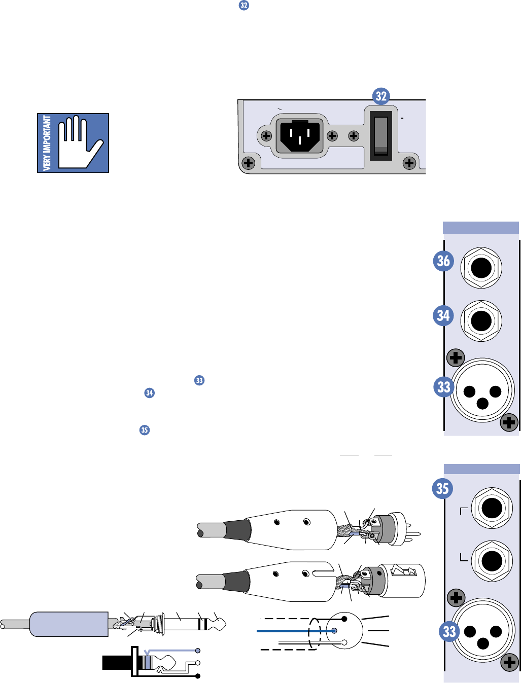
21
POWER switch
The
POWER
switch is located on the rear
panel of the mixer, near the linecord socket.
Switch up to turn the mixer on, and switch
down to turn it off.
The
TAPE IN LEVEL
control ranges from off
through unity (the center detent position) on
up to +15 dB of extra gain. Note that this
control only affects the
TAPE IN
level and not
the
TAPE OUT
level (there is no tape out level
control). The
TAPE OUT
level is pre-fader
(actually pre-Master in this case) and is not
affected by the
MAIN MASTER
control.
Caution: When using the
TAPE OUT
connectors for
recording, don’t connect
the output of the tape deck
to the
TAPE IN
connectors.
If you do, MAKE SURE the
TAPE IN LEVEL
control is turned all the way down or you will
create a feedback loop that will suddenly make
you the focus of attention.
POWER
120 VAC 60HZ 320W
ON
MIC 1
INSERT
LINE
RIGHT
MIC 8
LEFT/MONO
STEREO
MIC/
LINE
HI-Z
Stereo Channel Strip
Mono Channel Strip
2
2
31
1
SHIELD
COLD
HOT
SHIELD
COLD
HOT
3
SHIELD
COLD
HOT
3
2
1
Balanced XLR Connectors
SLEEVE (SHIELD)
TIPSLEEVE
TIP (HOT)
RING (COLD)
RING
TIP
SLEEVERING
Balanced 1/4" TRS Plug
MAKING THE CONNECTIONS
Front Panel Connections
Connecting Microphones and Line-Level
Signals
Each channel has both an XLR
MIC
input and a 1/4" TRS
LINE
input. In
addition, the two stereo channels on the 408M,
408S, 808M, and 808S each have two 1/4" TRS
line inputs, left and right . These two inputs
are summed together in the 408M and 808M,
and are routed to the left and right buses
respectively in the 408S and 808S. You can plug
a mono signal into the
LEFT
stereo input and
the signal is automatically routed to both the
left and right inputs.
Mackie mixers have 3-pin female XLR con-
nectors on all microphone inputs, so use a
male XLR connector to connect to the mixer’s
mic preamps.
The XLR and 1/4" TRS inputs are balanced
analog inputs. When connecting a balanced
signal using the XLR or 1/4" jacks, be sure
they’re wired — per AES (Audio Engineering
Society) standards — like this:
XLR TRS
Hot (+) Pin 2 Tip
Cold (–) Pin 3 Ring
Shield (Ground) Pin 1 Shield
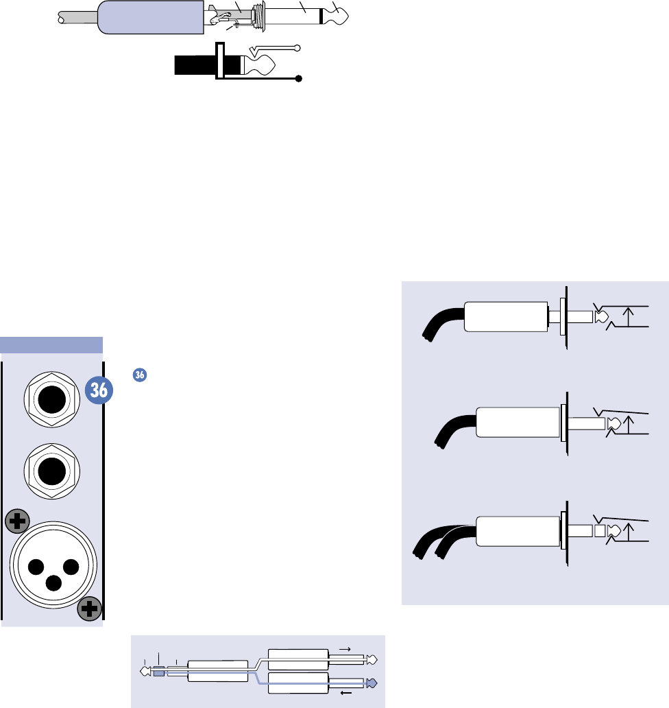
22
SLEEVE (SHIELD)
TIP (HOT)
TIPSLEEVE
TIP
SLEEVE
Unbalanced 1/4" TS Plug
The
INSERT
jack can also be used as a di-
rect out from the mic preamps to tape. If you
insert a TS (mono) 1/4" plug halfway into the
INSERT
jack (to the first click), the plug will
not activate the jack switch and will not open
the insert loop in the circuit (thereby allowing
the channel signal to continue on its merry way
through the mixer). This allows you to tap the
channel signal at that point in the circuit with-
out interrupting normal operation.
If you push the 1/4" TS plug in to the second
click, you will open the jack switch and create
a direct out, which does interrupt the signal in
that channel.
Do not overload or short-circuit the signal
you are tapping from the mixer. Doing so will
affect the internal signal.
Direct out with no signal interruption.
Insert only to first “click.”
Channel Insert jack
Channel Insert jack
Channel Insert jack
Direct out with signal interruption.
Insert all the way in to the second “click.”
For use as an effects loop.
(TIP = SEND to effect, RING = RETURN from effect.)
MONO PLUG
MONO PLUG
STEREO
PLUG
Unbalanced TS (tip-sleeve) lines can be ac-
commodated via the TRS jack. Make sure the
cord terminates with a TS plug (like a guitar
plug), or if it’s a TRS plug (like a headphone
plug), make sure the ring is tied to the shield,
preferably at the source.
You can connect an input signal to both the
MIC
input and the
LINE
input. The signals are
summed together prior to the
INPUT LEVEL
SET
control so they are both affected by it. On
the stereo channels 7 & 8, the inputs are
summed after the
INPUT LEVEL SET
control
and only the
MIC
input is affected by it.
Channel Inserts
The mono channels are equipped with
INSERT
jacks for connecting external processors into
each channel’s signal path. The insert point
comes after the Mic/Line preamp’s
INPUT LEVEL
SET
control and just before the EQ controls.
This is a TRS jack specially configured as a
combination Send/Return connection point. It is
configured with the Tip = Send, Ring = Return,
and Sleeve = Ground. This has become some-
what of a standard in the industry, and many
cable manufacturers make cables especially
for this purpose. With nothing plugged into the
INSERT
jack, the send signal is directly connected
to the return pin via the normalling jack.
“tip”
This plug connects to one of the
mixer’s Channel Insert jacks. “ring”
tip ring
sleeve
SEND to processor
RETURN from processor
(TRS plug)
Tip = Send (output to effects device)
Ring = Return (input from effects device)
Sleeve = Common ground (connect shield to all
three sleeves)
MIC
1
INSERT
LINE
Mono Channel Strip
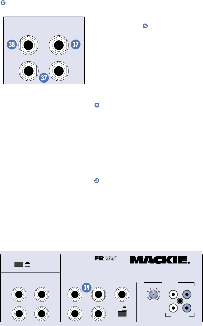
23
EFFECTS SEND and RETURN
EFX FOOT
SWITCH
RIGHT RETURNLEFT RETURN
SEND
EFFECTS
(OVERRIDES INTERNAL EFX)
The
EFFECTS SEND
jack is a 1/4" connector
that produces an unbalanced line-level signal.
This signal is fed from the internal EFX bus,
just after the
EFX DRIVE LEVEL
control.
Use a cable with 1/4" TS plugs to connect the
EFFECTS SEND
jack to the input of an external
effects processor. Use a similar cable (or cables)
to return the external effects processor’s signal
to the
EFFECTS RETURN
jack(s).
The mono versions (406M, 408M, 808M)
have one
EFFECTS RETURN
jack and the stereo
versions (408S, 808S) have two
RETURN
jacks.
These are 1/4" connectors that accept an un-
balanced line-level signal.
The
EFFECTS SEND
and
RETURN
are
normalling jacks, so with nothing plugged into
the
SEND
or
RETURN
jacks, the internal ef-
fects signal from the
EMAC
is routed to the
EFX TO MON
and
EFX TO MAIN
controls. If
you plug a 1/4" TS plug into the
EFFECTS RE-
TURN
jack(s), the effects signal from the
EMAC
is disconnected from the signal path.
Instead, the external effects signal is routed to
the
EFX TO MON
and
EFX TO MAIN
controls.
Note: If you want to use the internal
EMAC
and an external effects processor at the same
time, you have two options.
Serial effects device: The
EFFECTS SEND
jack is wired the same as the channel
INSERT
jacks, so you can use it to insert a processor in
series with the
EMAC
effects. Refer to the
“Channel Inserts” section to see how to
make this connection.
Parallel effects device: Plug a TS plug half-
way into the
EFFECTS SEND
jack (to the first
click). This allows you to use the
EFFECTS
SEND
jack as a direct out without affecting the
signal going to the
EMAC
. However, you must
use one of the
LINE
inputs (or one of the stereo
channel’s stereo line inputs if it’s a stereo pro-
cessor) to return the signal from the external
effects processor. If you plug into the
EFFECTS
RETURN
jack, the signal from the
EMAC
is dis-
connected from the signal path.
EFX FOOT SWITCH
You can connect a normally-open foot
switch to this connector to duplicate the
function of the
EFX BYPASS
switch. Closing
the switch connection causes the
EFX BYPASS
indicator to light and mutes the effects signal.
This affects both the internal
EMAC
and an
external effects processor (if connected) using
the
EFFECTS SEND
and
RETURN
jacks.
Note: When a foot switch is plugged into the
FOOT SWITCH
jack, the
EFX BYPASS
switch
is disabled.
POWER AMP IN 1 and 2
This is a 1/4" connector that accepts an un-
balanced line-level signal. Whatever signal you
plug into these jacks is routed to the power
amplifier inputs. This provides the ability to in-
sert a processor in the signal path between the
MIXER OUT
and the
POWER AMP IN
.
EFX FOOT
SWITCH
RIGHT RETURNLEFT RETURN
SEND
L MIXER OUT R MIXER OUT COMPRESSOR
L POWER
AMP IN
R POWER
AMP IN
EFFECTS
(OVERRIDES INTERNAL EFX) MONITOR
MAINS
TAPE IN
TAPE OUT
LEVEL
+15
U
OO
LINE
LR
R
L
OUT
408S
POWER AMP ROUTING
IN
OUT
STEREO MAINS
LEFT = MAIN
RIGHT = MONITOR
2 X 250W STEREO
Stereo Version Connector Section
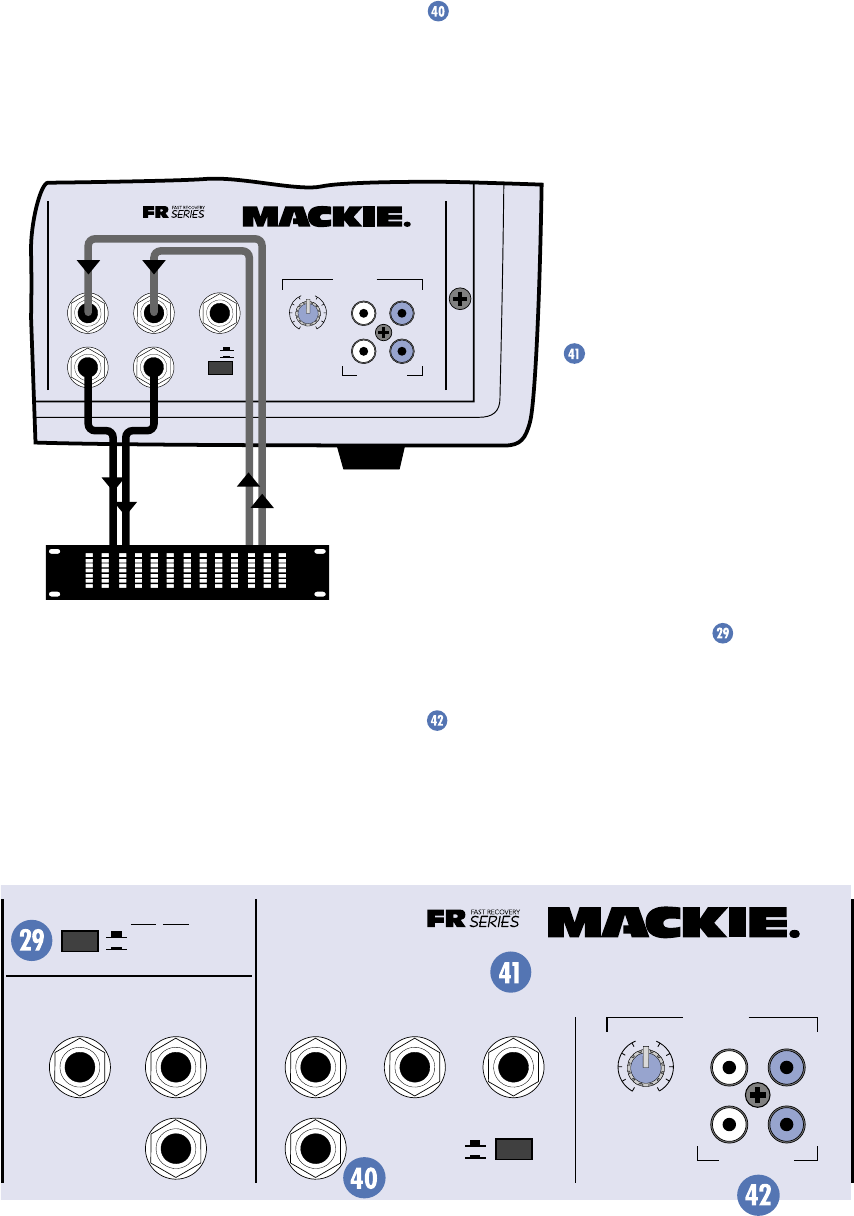
24
When a 1/4" plug is inserted in the POWER
AMP IN jacks, the internal connection between
the mixer section and the amplifier section is
cut.
This completely separates the mixer from
the amplifiers, and it allows you to connect an
external equalizer, compressor or effects pro-
cessor in-line between them as shown.
With a plug inserted in the POWER AMP IN
jacks, the amplifiers will only play the external
signals plugged into them. With no plug in-
serted, the mixer section and the amplifier
section are joined and the amplifiers play the
mixer signals as normal.
External equalizer,
compressor, or processor
OUT
IN
L MIXER OUT R MIXER OUT COMPRESSOR
L POWER
AMP IN
R POWER
AMP IN
MONITOR
MAINS
TAPE IN
TAPE OUT
LEVEL
+15
U
OO
LINE
LR
R
L
OUT
408S
IN
OUT
2 X 250W STEREO
If you have an external device in-line as
shown in the diagram above, make sure it does
not increase the signal gain too much, or it may
overload the amplifier section. The PPM
meters only show the signal level coming from
the internal mixer section; they will not show
any changes in gain due to the external device.
You might use these inputs to connect the
outputs from the opening band’s mixing board.
This way you don’t have to set up two sets of
speakers; the other band can plug right into
the PPM Series and use its amplifiers and con-
nected speakers (see application diagram on
page 13).
MIXER LINE OUT
This is a 1/4" connector that produces an
unbalanced line-level signal. This signal is fed
from the internal mixer bus, just after the
MAIN MASTER
control and
MAIN EQUALIZER
,
and just before the
POWER AMP IN
jacks.
You can use the
MIXER
LINE OUT
s to connect a sec-
ond power amplifier, giving
you the option of adding more
power and more speakers
(see application diagram on
page 10).
MONITOR LINE OUT
This is a 1/4" connector
that produces an unbalanced
line-level signal. This signal is
fed from the internal monitor
bus, just after the
MONITOR MASTER
control
and
MONITOR EQUALIZER
.
Use this connection to drive an external
monitor amplifier and speakers, or to supple-
ment the PPM Series’ monitor amplifier (when
the
POWER AMP ROUTING
switch is
pushed in) with another amplifier and speakers
(see application diagram on page 8).
TAPE IN and TAPE OUT
These are unbalanced RCA-type connectors
that match those typically used on tape decks
and CD players. Use RCA-to-RCA patch cables
to make these connections.
EFX FOOT
SWITCH
RETURN
SEND
MIXER LINE OUT
POWER
AMP 1 IN
POWER
AMP 2 IN
EFFECTS
(OVERRIDES INTERNAL EFX) MONITOR
MAINS
TAPE IN
TAPE OUT
LEVEL
+15
U
OO
LINE
LR
R
L
OUT
POWER AMP ROUTING
AMP 1
MAIN
MAIN MONITOR
AMP 2
MAIN
COMPRESSOR
IN
OUT
2 X 250 WATTS
408M
Mono Version Connector Section
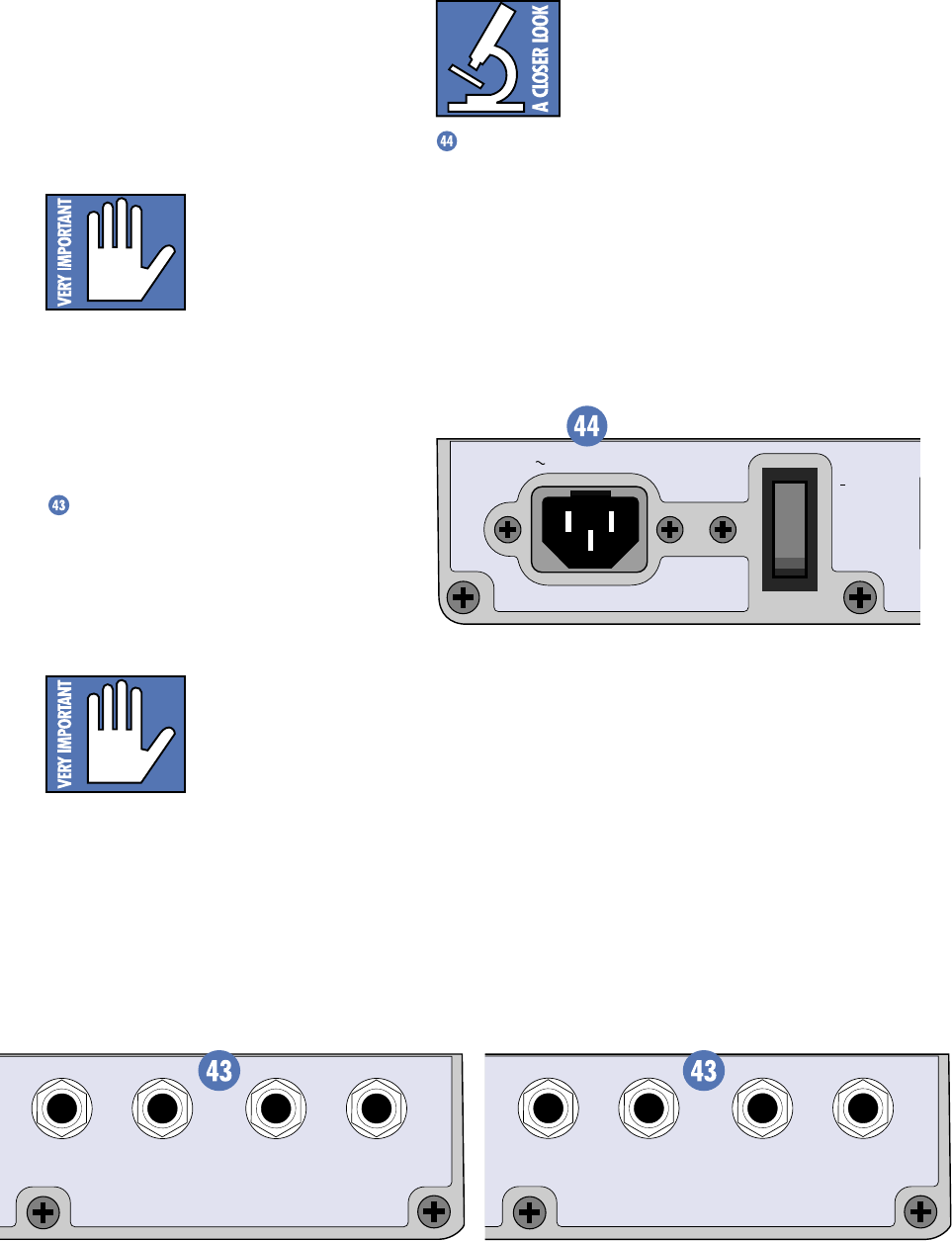
25
SPEAKER OUT
OUTPUT POWER: 250 WATTS / CHANNEL
MINIMUM SPEAKER LOAD: 2 OHMS / CHANNEL
SPEAKER OUT
LEFT / MAIN RIGHT / MONITOR
POWER
T
W
120 VAC 60HZ 320W
ON
SPEAKER OUT
OUTPUT POWER: 250 WATTS / CHANNEL
MINIMUM SPEAKER LOAD: 2 OHMS / CHANNEL
SPEAKER OUT
POWER AMP 1 / MAIN POWER AMP 2 / MONITOR
Stereo Version Speaker Connectors (408S) Mono Version Speaker Connectors (408M)
The
TAPE IN
signal is routed to the mixer
bus just after the
RUMBLE REDUCTION
switch
and just before the
TAPE IN LEVEL
control,
MAIN MASTER
control, and
MAIN EQUALIZER
.
The
TAPE OUT
signal is tapped just after the
RUMBLE REDUCTION
switch, and before the
MAIN MASTER
control and
MAIN EQUALIZER
.
Caution: When using the
TAPE OUT
connectors for
recording, don’t connect
the output of the tape deck
to the
TAPE IN
connectors.
If you do, MAKE SURE the
TAPE IN LEVEL
control is turned all the way down or you will
create a feedback loop that will cause great dis-
tress to you and everyone around you.
Rear Panel Connections
SPEAKER OUT
This is a 1/4" connector that produces an
unbalanced speaker-level signal.
Use 1/4" TS speaker cables to connect the
SPEAKER OUT
s to the inputs of your speakers.
Use at least 18 gauge (18AWG) speaker wire.
Caution: Don’t use standard
guitar cables to make these
connections. Guitar cords
are designed for line-level
signals (millivolts and
milliamps), not speaker-level signals (several
volts and several amps).
There are two
SPEAKER OUT
jacks for each
amplifier. The jacks are wired in parallel so if
you connect two speakers to an amplifier, the
load presented to the amplifier is the parallel
impedance of both speakers. This impedance
must be two ohms or greater.
For parallel connections:
8 ohms + 8 ohms = 4 ohms
4 ohms + 4 ohms = 2 ohms
IEC Socket
This is where you connect the supplied AC
linecord to provide AC power to the PPM Series
powered mixer. Plug the linecord into an AC
socket properly configured for your particular
model.
Note: If you happen to lose the AC linecord,
replacements are easily available at any office/
computer supply store or Radio Shack
®
(ask
for part number 278-1257).

26
GENERAL PRECAUTIONS AND CONSIDERATIONS
NEVER bypass the AC
plug’s ground pin. This is
dangerous!
It is recommended that a stiff (robust)
supply of AC power be used because the amp-
lifiers place high momentary current demands
on the AC line. The more power that is available
on the line, the louder the amplifiers will play
and the more peak output power will be
available for cleaner, punchier bass. A suspected
problem of “poor bass performance” is often
caused by a weak AC supply to the amplifiers.
AC Power Distribution
The majority of AC outlets encountered in
homes and clubs (in the U.S.) are served by a
240VAC center-tapped service entrance trans-
former. This provides two phases of AC power
on either side of the center tap, at 120V each.
If lighting is used in a show, it is preferable
to power the lights from one leg of the service,
and power the audio equipment from the other
leg. This will help minimize noise from the
lights coupling into the audio (particularly if
SCRs, or light-dimmer switches, are used).
In order to minimize ground loops, the safety
grounds for all the outlets should be connected
to a common (“star”) grounding point, and the
distance between the outlets and the common
grounding point should be as short as possible.
When setting up for a show, oftentimes you
are plugging into an AC power distribution sys-
tem you know nothing about. You may even be
faced with 2-wire outlets that are missing the
third safety ground pin. It’s a good idea to have
a three-wire AC outlet tester in your toolbox so
you can check the outlets yourself to make
sure they are wired correctly. These testers will
tell you if the polarity of the hot and neutral
wires is reversed and if the safety ground is
disconnected. Don’t use an outlet if it is wired
improperly! This is to protect yourself as well
as your equipment.
If you find that you must plug into a two-wire
outlet, you will need to use a two-wire to three-
wire adapter (cheater plug). These come with a
metal tab that you put underneath the center
screw that holds the AC outlet faceplate in place.
This center screw must be grounded. You can
check it by connecting the adapter to the outlet
and then plugging in your handy-dandy AC
outlet tester.
Thermal Considerations
The PPM Series Powered Mixers contain
two powerful built-in amplifiers. All amplifiers
produce heat, and the more power it produces,
the more heat is produced. It is important to
dissipate the heat away from an amplifier as
quickly as possible. This results in increased
reliability and longevity for the amplifier. That’s
what the massive die-cast aluminum heatsink
on the rear panel is for.
Heat from the output transistors is coupled
to the heatsink, which draws the heat away
from the transistors and out to the heatsink
fins. Cool air is drawn through the fins due to a
process called convection, warming the air and
taking the heat away.
In order for this convection cooling to work
efficiently, it is important to provide adequate
airspace behind the mixer. We recommend
leaving at least six inches of air space behind
the mixer when you set it up.
In the unlikely event of the amplifier overheat-
ing, a thermal switch activates and shuts down
the mixer until it cools off. Double-check the
speaker load on each amplifier and make sure
that the total impedance of each load is 2 ohms or
greater. If the load impedance drops below 2 ohms,
it can cause the amplifier to overheat. If the load
impedance is okay, overheating may be caused by
excessive ambient temperature (the room’s too
hot!). Try using a fan aimed at the heatsink to
move air through the fins faster.
AC Power Considerations
Be sure the PPM Series Powered Mixer is
plugged into an outlet that is able to supply the
correct voltage specified for your model. If the
voltage should drop below 97% of the specified
line voltage, the built-in amplifiers will no
longer be able to supply rated power. (They will
continue to operate down to 75% of the rated
voltage, but won’t reach full power, resulting in
lower headroom.)
Under typical conditions, reproducing music
where musical peaks are just below clipping,
the powered mixers draw the following average
currents:
Average Current
Amplifier Loading 406M, 408M, 408S 808M, 808S
8Ω per side 2.0 A 2.2 A
4Ω per side 3.1 A 3.3 A
2Ω per side 4.8 A 5.0 A
(Above current based on using 120V AC line)
27
APPENDIX A: Service Info
• Is the channel’s
VOLUME
control and
the
MAIN MASTER
control properly set?
Refer to the “Level Setting Procedure” on
page 6.
• Is there something plugged into the
channel’s
INSERT
jack? Plugging into the
INSERT
jack breaks the signal path for
the channel. Try unplugging any
INSERT
devices. If that fixes the problem, make
sure you’re using a properly wired send/
return cable (see “Making the Connec-
tions” on page 21). Make sure the
volume (gain) controls on the external
processor connected to the
INSERT
jack
are properly set.
• Is there something plugged into the
POWER AMP IN
jacks? Plugging into the
POWER AMP IN
jacks breaks the signal
path between the mixer and the ampli-
fier. However, the signal source you have
plugged into the
POWER AMP IN
jacks
should be heard over the speakers
connected to the
SPEAKER OUT
jacks.
• Do you have any external equalizers,
compressors or processors connected
between the
MIXER OUT
and
POWER
AMP IN
jacks? If so, make sure they are
working correctly.
• Are there fuses in the speaker or in-line
fuses in the speaker wire? Check ’em to
see if they’re blown.
• Are the speakers working properly? If
you have another amplifier that you
know works, plug the speakers into it to
make sure they work.
One side is way louder than the other!
For the 408S and 808S:
• Do the
LEVEL
meters read the same on
both sides? If not, the
PAN
control on
the signal source’s channel strip may be
turned too far to one side. If you’re using
a stereo signal source, it may be deliver-
ing an out-of-balance stereo signal.
• Try swapping sides: Turn off the powered
mixer, swap the speaker cables at the
SPEAKER OUT
jacks, turn the mixer
back on. If the same side is still louder,
the problem is with your speakers or
speaker cabling. If the other side is
louder now, the problem is with the
mixer, the amp, or the signal source.
Warranty Service
If you think your powered mixer has a prob-
lem, please do everything you can to confirm it
before calling for service, including reading
through the following Troubleshooting section.
Of all Mackie products returned for service
(which is hardly any at all), many are coded
“CND” — Could Not Duplicate, which usually
means the problem lay somewhere else in the
system. Here are some things you can check:
Troubleshooting
No power!
• Our favorite question: Is it plugged in?
Make sure the AC outlet is live (check
with a tester or lamp).
• Our next favorite question: Is the
POWER
switch on? If not, try turning it on.
• Is the green
POWER
light on the front
panel illuminated? If not, make sure the
AC outlet is live. If so, refer to “No
sound” below.
• The AC line fuse inside the mixer is
blown. This is not a user-serviceable
part. Refer to “Repair” on page 28 to find
out how to proceed.
No sound!
• Are the
INPUT LEVEL SET
controls
turned all the way down? Follow the
procedures in the “Quick Start” section
on page 6 to verify that all the level and
volume controls are properly adjusted.
• Is the signal source working (and
making union scale)? If it’s a micro-
phone, make sure the mic cable is in
good repair and securely connected at
both ends. If it’s a condenser micro-
phone, make sure the
PHANTOM
POWER
switch is turned on. If it’s an
instrument, again make sure the con-
necting cables are in good repair and
securely connected at both ends. Make
sure the output volume (gain) control
for the instrument is turned up suffi-
ciently to drive the inputs of the mixer.
You should be able to see the
INPUT
LEVEL SET
LED blink when you turn up
the
INPUT LEVEL SET
control.
If you’re monitoring the
TAPE IN
, make
sure the tape deck’s Tape/Source switch
is set to “Tape,” and make sure the
TAPE
IN LEVEL
control on the powered mixer
is turned up to unity (center position).
28
The bass frequencies diminish when
standing center, but get louder as you
approach one side!
• Check the polarity of the speaker cable
connections. You may have your positive
and negative connections reversed at
one end of one speaker cable.
As soon as the music gets loud, the mixer
shuts down!
• Check the
LEVEL
meters. Be sure that
the
CLIP
LED is not lighting up
frequently or continuously.
• Make sure there is room behind the
powered mixer to provide sufficient
ventilation to the heatsink. If it gets too
hot, it will shut down the show.
• Is the total speaker impedance connected
to each amplifier 2 ohms or greater? If
the impedance is too low, the amplifier
may overheat and shut down.
It hurts when I touch my arm, or my leg, or
even my head!
• You have a broken finger.
Bad sound!
• Is it loud and distorted? Follow the
procedures described in the “Quick
Start” section to verify that the levels are
set properly.
• Is the input connector plugged completely
into the jack? Check the speaker connec-
tions and verify that all connections are
tight and that there are no stray strands of
wire shorting across the speaker terminals.
• Keep practicing.
Noise/Hum
• Turn the channel
VOLUME
knobs down
one by one. If the noise disappears, it’s
either that channel or whatever is
plugged into it. If not, turn down the
EFX
TO MAIN
control. If the noise disappears,
it could be coming from an external
effects device plugged into the
EFFECTS
RETURN
jack(s).
• Make sure all connections to the pow-
ered mixer are good and sound.
• Make sure none of the signal cables are
routed near AC cables, power transform-
ers, or other EMI-inducing devices.
• Is there a light dimmer or other SCR-
based device on the same AC circuit as
the powered mixer? Use an AC line filter
or plug the powered mixer into a differ-
ent AC circuit.
• Is there an external processor or other
electronic device connected to the
powered mixer? Make sure it is plugged
into the same AC circuit as the powered
mixer to reduce the possibility of creat-
ing a ground loop.
• Refer to “Grounding” in Appendix B.
There’s sound in the monitors even though
all the channel MONitor controls are turned
down!
• Make sure the
EFX TO MON
control is
turned down. This control adds the “wet”
effects signal to the monitor output even
when there is no monitor signal present.
Repair
Service for the PPM Series Powered Mixers
is available only from one of our authorized do-
mestic service stations or at the factory, located
in sunny Woodinville, Washington. Service for
Mackie Powered Mixers living outside the
United States can be obtained through local
dealers or distributors.
If your powered mixer needs service, follow
these instructions:
1. Review the preceding troubleshooting
suggestions. Please.
2. Call Tech Support at 1-800-258-6883, 8am
to 5pm PST, to explain the problem and
request an RA (Return Authorization)
number. Have your powered mixer’s serial
number ready. You must have an RA
number before you can obtain service at
the factory or an authorized service center.
3. Keep this owner’s manual. We don’t need it
to repair the powered mixer.
4. Pack the powered mixer in its original
package, including endcaps and box. This
is very important. When you call for the
RA number, please let Tech Support know
if you need new packaging. Mackie is not
responsible for any damage that occurs
due to non-factory packaging.
5. Include a legible note stating your name,
shipping address (no P.O. boxes), daytime
phone number, RA number, and a detailed
description of the problem, including how
we can duplicate it.
29
Unbalancing a Line
In most studio, stage, and sound reinforce-
ment situations, there is a combination of
balanced and unbalanced inputs and outputs
on the various pieces of equipment. This
usually will not be a problem in making
connections.
• When connecting a balanced output to
an unbalanced input, be sure the signal high
(hot) connections are wired to each other, and
that the balanced signal low (cold) goes to the
ground (earth) connection at the unbalanced
input. In most cases, the balanced ground will
also be connected to the ground at the unbal-
anced input. If there are ground-loop problems,
this connection may be left disconnected at the
balanced end.
• When connecting an unbalanced output
to a balanced input, be sure that the signal
high (hot) connections are wired to each
other. The unbalanced ground (earth) connec-
tion should be wired to the low and the ground
connections of the balanced input. If there are
ground-loop problems, try connecting the un-
balanced ground connection only to the input
low connection, and leaving the input ground
connection disconnected.
• In some cases, you will have to make up
special adapters to interconnect your equip-
ment. For example, you may need a balanced
XLR female connected to an unbalanced 1/4"
6. Write the RA number in BIG PRINT on
top of the box.
7. Ship the powered mixer to us. We suggest
insurance for all forms of cartage. Ship to
this address:
Mackie Designs
SERVICE DEPARTMENT
16140 Wood-Red Rd. NE, Ste. 5
Woodinville, WA 98072
Balanced Lines
Balanced lines offer increased immunity
to external noise (specifically, hum and buzz).
Because a balanced system is able to minimize
noise, it is the preferred interconnect method,
especially in cases where very long lengths of
cable are being used. A long unbalanced cable
carries with it more opportunity for noise to get
into a system — having balanced inputs means
very little noise will enter the system via snakes
and other cables that typically must run a long
length.
A balanced line is a three-wire system where
two wires carry the signal and the third is a
ground wire that shields the inner conductors
from EMI. The two inner conductors carry the
same signal, but with opposite polarity. The
balanced input amplifies only the difference
between the two conductors. But a signal that
is common to both conductors, and in phase, is
rejected (canceled out) at the balanced input.
This includes hum from AC lines or other EMI
induced noise.
An unbalanced line does not have this
noise-rejecting capability because it has only
two conductors. One conductor carries the sig-
nal and the other is a ground wire that shields
the inner conductor. Any hum or EMI noise
that gets through the shield is added to the sig-
nal and amplified at the unbalanced input.
Often the hum can be louder than the signal itself!
APPENDIX B: Some Arcane Mysteries Illuminated
8. We’ll try to fix the mixer within three
business days. Ask Tech Support for
current turn-around times when you call
for your RA number. We normally send
everything back prepaid using UPS Orange
(three-day air). However, if you rush your
powered mixer to us by next-day air, we’ll
treat it in kind by shipping it back the same
way in which it was received. This para-
graph does not necessarily apply to
non-warranty service.
30
TS phone plug. The balanced-to-unbalanced
connection has been anticipated in the wiring
of Mackie jacks. A 1/4" TS plug inserted into a
1/4" TRS balanced input, for example, auto-
matically unbalances the input and makes all
the right connections. Conversely, a 1/4" TRS
plug inserted into a 1/4" unbalanced input
automatically ties the ring (low or cold) to
ground (earth).
Grounding
Grounding exists in your audio system for
two reasons: product safety and noise reduc-
tion. The third wire on the power cord exists
for product safety. It provides a low-resistance
path back to the electrical service to protect
the users of the product from electrical shock.
Hopefully, the resistance to ground through the
safety ground (third wire) is lower than that
through the user/operator to ground. If you re-
move this connection (by breaking or cutting
the pin off, or by using a ‘ground cheater’), this
alternate ground path ceases to exist, which is
a safety hazard.
The metal chassis of the product, the
ground connections provided by the various
connectors, and the shields within your con-
necting cables provide a low-potential point for
noise signals. The goal is to provide a lower im-
pedance path to ground for noise signals than
through the signal wiring. Doing so helps
minimize hum, buzz, and other extraneous
non-audio signals.
Many “authorities” tell you that shields
should be connected only at one end. Some-
times this can be true, but for most (99%)
audio systems, it is unnecessary. If you do ev-
erything else correctly, you should be able to
connect every component of your audio system
using standard, off-the-shelf connecting cables
that are available at any music store.
Here are some guidelines:
1. Use balanced lines if at all possible. They
provide better immunity to induced noise
and ground loops. Remember that you can
balance a line by inserting in-line a piece of
equipment that has a balanced output.
2. Avoid using three-phase power lines since
they are usually used for air conditioning
and other heavy power equipment. If using
240VAC single phase with center-ground
power, connect all audio equipment to one
side of the AC power, and all lighting and
other equipment to the other side.
3. Be sure all AC outlet safety grounds are
connected to one common point in a star
ground arrangement. This common ground
point should then tie back to earth ground
at the service entrance by one heavy
stranded wire, #2 gauge or larger.
4. Don’t cut the third pin off the power cord.
Carry some ground-lifter adapters and use
them only if you have to plug into an
ancient two-wire outlet.
5. Cables that are too long are less likely to
pick up hum if you uncoil them in their
entirety, and then find a place to stow the
excess. Leaving the excess coiled only helps
the cable pick up hum more efficiently.
6. If you bundle your cables together, don’t
bundle AC wiring and audio wiring to-
gether. Bundle them separately.
7. If your sound system insists on humming,
you may want to teach it the words.

31
Maximum Input Levels
Mic Input: –20 dBu, Trim @ 0 dB (HI)
+20 dBu, Trim @ –40 dB (LOW)
Line Input: 0 dBu, Trim @ 0 dB (HI)
+40 dBu, Trim @ 40 dB (LOW)
Insert Input: +20 dBu
Stereo Line Input: +20 dBu
Tape Input: +20 dBu
Effects Return: +20 dBu
Power Amp In: +22 dBu
Input Sensitivity
Minimum Input Level to produce +4 dBu @ Main
Mixer Output
Mic Input: –68 dBu
Insert Input: –28 dBu
Line Input: –48 dBu
Stereo Line Input: –28 dBu
Tape Input: –18 dBu
Effects Return: –18 dBu
Maximum Voltage Gain
Mic Input to
Insert Output: 40 dB
Tape Output: 60 dB
Main Mixer Output: 72 dB
Line Input to
Insert Output: 20 dB
Tape Output: 20 dB
Main Mixer Output: 52 dB
Stereo Line Input to
Tape Output: 20 dB
Main Mixer Output: 32 dB
Tape Input to
Tape Output: 10 dB
Main Mixer Output: 22 dB
Effects Return to
Main Mixer Output: 22 dB
Monitor Output: 22 dB
Input Impedance
Mic Input: 3kΩ, balanced
Insert Input: 10kΩ, unbalanced
Line Input: 40kΩ, balanced
Stereo Line Input: 10kΩ, unbalanced
Tape Input: 10kΩ, unbalanced
Effect Return: 10kΩ, unbalanced
Power Amp In: 10kΩ, unbalanced
Output Impedance
Main Mixer Output: 150Ω
Insert Output: 150Ω
Tape Output: 150Ω
Monitor Output: 150Ω
Effects Send: 150Ω
Power Amp Out: 0.032Ω @ 1kHz
Digital Effects
Resolution: 16-bit, 2-channel
Sample Rate: 31.25kHz
Bandwidth: 15.6kHz
VU Meters
Main and Monitor
8 segments: Clip, +5, 0, –5, –10, –15, –20, –30
APPENDIX C: Technical Info
Specifications
PPM Series Powered Mixers
406M, 408M, 408S, 808M, 808S
Mixer Section
Frequency Response
Mic Input to Main Mixer Output (Trim at 0 dB):
+0, –1 dB, 32Hz to 20kHz
+0, –3 dB, 16Hz to 80kHz
Mic Input to Power Amp Output @ rated power output:
+0, –1 dB, 32Hz to 20kHz
+0, –3 dB, 16Hz to 55kHz
Distortion
THD and SMPTE IMD; 20Hz to 20kHz
Mic Input to Main Mixer Output:
< 0.005% @ +4 dBu output
Mic Input to Power Amp Output:
< 0.15%, 250mW to rated power
Common Mode Rejection Ration (CMRR)
60 dB @ 1kHz, Trim @ 0 dB
Noise
20Hz to 20kHz BW (150Ω source impedance)
Equivalent Input Noise (EIN):
–127 dBu
Residual Output Noise:
Main Mixer, Monitor, & Effects outputs
Channel & Master levels off
–95 dBu
Main Mixer Output Noise:
Master @ nominal (–10 dB), all channels off
–92 dBu
Master & 1 input channel @ nominal
(–10 dB & –20 dB), Trim @ 0 dB
–85 dB
Crosstalk
Adjacent Inputs or Input to Output:
–90 dB @ 1kHz
Fader Off
–90 dB @ 1kHz
Break Switch Mute
–80 dB @ 1kHz
Input Level Trim Control Range
0 to –40 dB
Phantom Power
+15V DC
Equalization
Rumble Reduction: 75Hz, –18 dB/octave
Channel EQ:
High ±15 dB @ 12kHz
Mid ±12 dB @ 2.5kHz
Low ±15 dB @ 80Hz
Graphic EQ (9 bands):
Q = 1.414, ISO octave centers
±15 dB @ 63, 125, 250, 500 1k, 2k, 4k, 8k, 16k Hz
Main Mixer Section Rated Output
Main Mixer, Monitor, & Effects: +4 dBu
Maximum Main Mixer Section Output: +20 dBu

32
Power Amplifier Section
Maximum Power at 1% THD, midband, both
channels driven
406M, 408M, 408S
250 watts per channel into 2Ω
200 watts per channel into 4Ω
125 watts per channel into 8Ω
808M, 808S
600 watts per channel into 2Ω
450 watts per channel into 4Ω
300 watts per channel into 8Ω
Continuous Sine Wave Average Output Power,
both channels driven (rated power)
406M, 408M, 408S
180 watts per channel into 4Ω from 40Hz to 20kHz,
with no more than 0.15% THD
110 watts per channel into 8Ω from 40Hz to 20kHz,
with no more than 0.10% THD
808M, 808S
340 watts per channel into 4Ω from 40Hz to 20kHz,
with no more than 0.15% THD
240 watts per channel into 8Ω from 40Hz to 20kHz,
with no more than 0.10% THD
Power Bandwidth
< 10Hz to 30kHz (+0, –1 dB) @ rated power into 4Ω
Frequency Response
< 10Hz to 30kHz (+0, –1 dB)
< 10Hz to 55kHz (+0, –3 dB)
Distortion
THD, SMPTE IMD: < 0.10% @ 8Ω
< 0.15% @ 4Ω
Signal-to-Noise Ratio
> 105 dB below rated power into 8Ω
Channel Separation
> 75 dB @ 1kHz
Damping Factor
> 250 @ 1kHz
Amp Input Impedance
10kΩ unbalanced, 20kΩ balanced
Input Sensitivity
406M, 408M, 408S
1.35 volts (+4.8 dBu) for rated power into 4 ohms
808M, 808S
1.76 volts (+7.1 dBu) for rated power into 4 ohms
Gain (Amp In to Speaker Out)
26.4 dB (21V/V)
Maximum Input Level
9.75 volts (+22 dBu)
Rise Time
406M, 408M, 408S < 5µs
808M, 808S < 6.2µs
Slew Rate
406M, 408M, 408S > 40V/µs
808M, 808S > 50V/µs
Load Angle
8(±jx) time independent at 8Ω
4(1±jx) time dependent at 4Ω
High Frequency Overload and Latching:
No latch up at any frequency or level.
High Frequency Stability:
Unconditionally stable, driving any reactive or
capacitive load
Turn On Delay:
3 seconds
AC Power Requirements
United States: 120VAC, 60Hz
Europe: 240VAC, 50Hz
Japan: 100VAC, 50/60Hz
Korea: 220VAC, 60Hz
(Capable of operation from 75% to 110% of rated line
voltage)
Physical
Height: 11.7 inches (297mm)
Width: 20.5 inches (521mm)
Overall Depth: 13 inches (330mm)
Weight:
406M, 408M, 408S 32 pounds (14.5 kg)
808M, 808S 36 pounds (16.3 kg)
Disclaimer
Since we are always striving to make our products
better by incorporating new and improved materials,
components, and manufacturing methods, we reserve
the right to change these specifications at any time
without notice.
This product is sold by weight, not by volume.
Contributors and Colophon
This manual was written and laid out by David Franzwa at
Mackie Galactic Headquarters overlooking the beautiful
Sammamish Slough in sunny Woodinville, WA. Input was
provided by the following Mackoids:
Steve Eborall, technical writer; Sara Delahan, Art Director;
Paul Larson, Tech Support Maestro; Rick Bos, Powered Mixer
Product Manager and on-staff tall person; Jeff Gilbert, long-
time Mackoid and technical advisor; CJ Murray, project engineer.
Proofreading provided by the ever-faithful Linn Compton.
Additional tidbits provided by Rick Chinn and Ron Koliha.
Preliminary text was written on a Power Macintosh
®
8100/
100AV using Microsoft
®
Word 98. Typesetting was performed
on the same Power Macintosh using Adobe
®
PageMaker
®
6.5.
Illustrations were created using Adobe
®
Illustrator
®
7.0. Fonts
used include ITC Century Light Condensed, Avenir Demi, and
Tekton. Subheadings were made with Futura Condensed. Font
management provided by Adobe
®
Type Manager
®
Deluxe 4.0
and Type Reunion
®
Deluxe 2.0.
“Mackie,” the “Running Man” figure, “PPM Series,”
“FR Series,” and “EMAC” are trademarks or registered trademarks
of Mackie Designs Inc.
All other brand names mentioned are trademarks or registered
trademarks of their respective holders, and are hereby acknowledged.
®
©2002 Mackie Designs Inc.
All Rights Reserved.
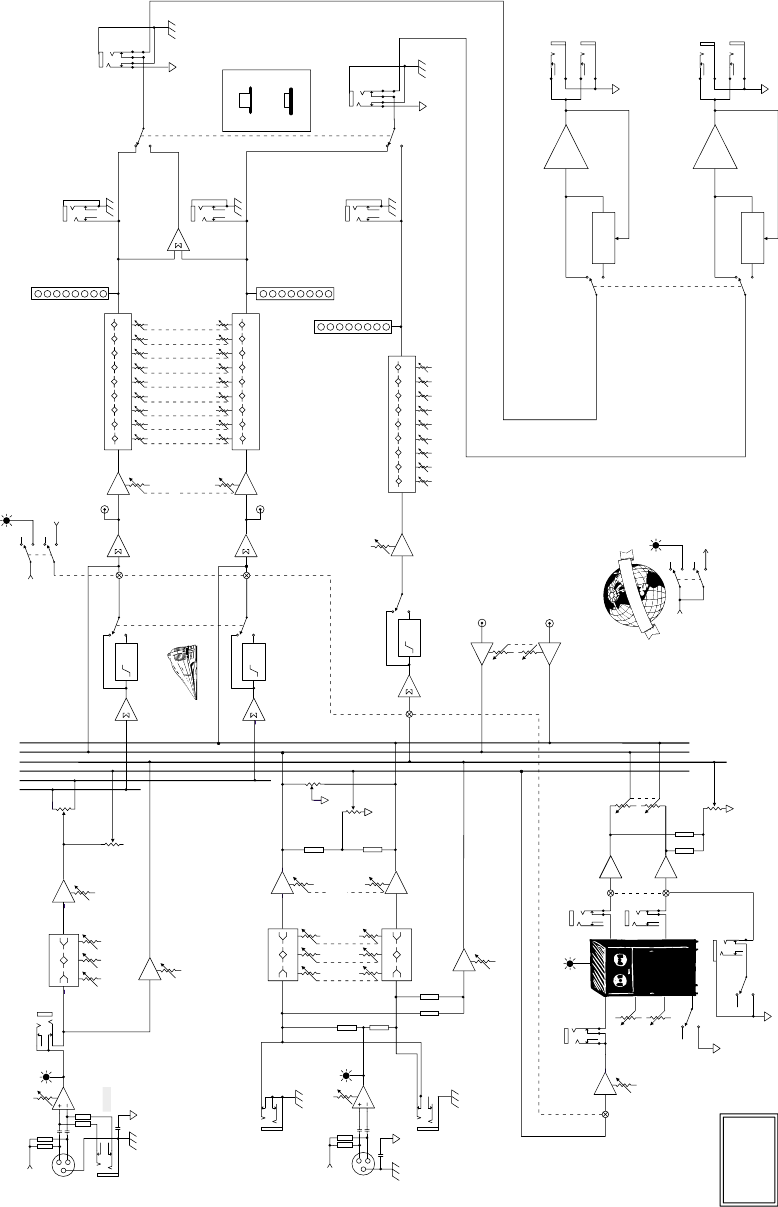
33
Block Diagrams
PPM Series Powered Mixers
Stereo Versions (408S, 808S)
63 125
250 500
1K 2K 4K 8K 16K
DAMPING/DEPTH
TIME/RATE
EFX WIDE
10
5
0
-5
-10
-15
-30
-40
-20dB
L
R
MID HI
80 2K5 12K
LO
75Hz
HPF
75Hz
HPF 63 125
250 500
1K 2K 4K 8K 16K
10
5
0
-5
-10
-15
-30
-40
10
5
0
-5
-10
-15
-30
-40
75Hz
HPF 63 125
250 500
1K 2K 4K 8K 16K
PHANTOM
+15V DC
MID HI
80 2K5 12K
LO
MID HI
80 2K5 12K
LO
COMPRESSOR
COMPRESSOR
PHANTOM
TRIM
(INPUT LEVEL SET)
0 to 40dB
G
L
O
B
A
L
P
H
A
N
T
O
M
P
O
W
E
R
PWR AMP
GROUND
CHASSIS
GROUND
PWR AMP
GROUND
CHASSIS
GROUND
RIGHT POWER
AMP IN
MIC/LINE
CH 1-6
3-BAND EQ
+/- 15dB
+/- 15dB
+/- 15dB
+VDC
+VDC
BREAK
(MUTES CH 1-6, EFX,
AND MONITOR)
PHANTOM
L'
R'
EFX
MON
L
R
EFX
EFX
TO M ONITOR
EFX
TO MAIN
EFX BYPASS
EFX CLIP EFX RETURN L
EFX SEND
LEFT POWER
AMP IN
AMP ROUTING
TAPE IN
TAPE OUT L
STEREO MAINS
MAIN/MONITOR
MONITOR
EFX
PA N
VOLUME
MONITOR
EFX
PA N
TRIM
(INPUT LEVEL SET)
TAPE OUT R
MAIN MASTER
LEVEL
MONITOR LEVEL
STEREO
CH 7-8
INSERT
0 to 40dB
Off to +20dB
Off to +20dB
Off to +10dB
+/- 15dB
Off to +12dB
Off to +20dB
Off to +10dB
Off to +12dB
Off to +10dB
Off to +10dB
Off to +12dB
Off to +10dB
EFX RETURN R
RIGHT MIXER
OUT
LEFT MIXER
OUT
MONITOR
LINE OUT
+/- 15db
+/- 15db
3-BAND EQ
9-BAND EQ
9-BAND EQ
9-BAND EQ
3-BAND EQ
EFX
FOOT
SWITCH
LEVEL
MACKIE DESIGNS
PPM STEREO
BLOCK DIAGRAM
(212029CJM/DF/SE)
LEFT AMP
LEFT SPEAKER
OUT
RIGHT AMP
RIGHT SPEAKER
OUT
RUMBLE FILTER
RUMBLE FILTER
RUMBLE FILTER
TAPE IN
LEVEL
VOLUME
Off to +20dB
LEFT/
MONO
RIGHT
EMAC
DSP
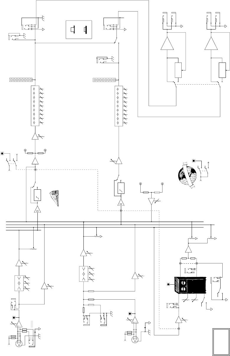
34
Mono Versions (406M, 408M, 808M)
63 125
250 500
1K 2K 4K 8K 16K
EFX RET L
EFX RET R
EFX WIDE
10
5
0
-5
-10
-15
-30
-40
-20dB
L
R
MID HI
80 2K5 12K
LO
75Hz
HPF
10
5
0
-5
-10
-15
-30
-40
75Hz
HPF 63 125
250 500
1K 2K 4K 8K 16K
MID HI
80 2K5 12K
LO
COMPRESSOR
COMPRESSOR
PHANTOM
TRIM
(INPUT LEVEL SET)
0 to 40dB
PHANTOM
+15V DC
G
L
O
B
A
L
P
H
A
N
T
O
M
P
O
W
E
R
PWR AMP
GROUND
CHASSIS
GROUND
LEFT POWER
AMP IN
PWR AMP
GROUND
CHASSIS
GROUND
RIGHT POWER
AMP IN
DAMPING/DEPTH
TIME/RATE
MIC/LINE
CH 1-6
3-BAND EQ
+/- 15dB
+/- 15dB
+VDC
+VDC
BREAK
(MUTES CH 1-6, EFX,
AND MONITOR)
PHANTOM
MAIN'
EFX
MON
MAIN
EFX
EFX
TO M ONITOR
EFX
TO MAIN
EFX BYPASS
EFX CLIP
EFX RETURN
MIXER
LINE OUT
AMP ROUTING
TAPE IN
TAPE OUT L
MAINS
MAIN/MONITOR
MONITOR
EFX
VOLUME
MONITOR
EFX
TRIM
(INPUT LEVEL SET)
TAPE OUT R MAIN MASTER
LEVEL
MONITOR LEVEL
STEREO
CH 7-8
(Not Available
on the 406M)
INSERT
0 to 40dB
Off to +20dB
Off to +20dB
Off to +10dB
+/- 15dB
Off to +12dB
Off to +20dB
Off to +10dB
Off to +12dB
Off to +10dB
Off to +10dB
Off to +12dB
Off to +10dB
MONITOR
LINE OUT
+/- 15db
3-BAND EQ
9-BAND EQ
9-BAND EQ
EFX
FOOT
SWITCH
LEVEL
MACKIE DESIGNS
PPM MONO
BLOCK DIAGRAM
(#21202CJM/DF/SE)
LEFT AMP
LEFT SPEAKER
OUT
RIGHT AMP
RIGHT SPEAKER
OUT
RUMBLE FILTER
RUMBLE FILTER
TAPE IN
LEVEL
VOLUME
Off to +20dB
LEFT/
MONO
RIGHT
EFX SEND
LEFT SPEAKER
OUT
EMAC
DSP

35
NOTES

®
®
®
™
Mackie Designs Inc.
Mackie Designs Inc.
16220 Wood-Red Rd. NE • Woodinville, WA 98072 • USA
US & Canada: 800/898-3211
Europe, Asia, Central & South America: 425/487-4333
Middle East & Africa: 31-20-654-4000
Fax: 425/487-4337 • www.mackie.com
E-mail: sales@mackie.com
Some of the
people at our
factory who helped
design, build, sell,
and support your
product.
Some of the
people at our
factory who helped
design, build, sell,
and support your
product.
