Mackie Sa1521 Users Manual 2 Way Active Speaker System User's
Mackie SA1521 Owner's Manual sa1521_om Mackie - SA1521 - Owner's Manual
SA1521 to the manual bbe859d0-296b-46d3-abd9-aaf1958d23fb
Mackie SA1521 Owner's Manual sa1521_om Mackie - SA1521 - Owner's Manual
2015-02-02
: Mackie Mackie-Sa1521-Users-Manual-436547 mackie-sa1521-users-manual-436547 mackie pdf
Open the PDF directly: View PDF ![]() .
.
Page Count: 12
SA
1521
2-WAY ACTIVE
SPEAKER SYSTEM
USER’S MANUAL
2
PORTABLE CART WARNING
Carts and stands - The
Component should be used
only with a cart or stand
that is recommended by
the manufacturer.
A Component and cart
combination should be
moved with care. Quick
stops, excessive force, and
uneven surfaces may cause
the Component and cart
combination to overturn.
SAFETY INSTRUCTIONS
1. Read Instructions — All the safety and operation instructions
should be read before this Mackie product is operated.
2. Retain Instructions — The safety and operating instructions
should be kept for future reference.
3. Heed Warnings — All warnings on this Mackie product and in
these operating instructions should be followed.
4. Follow Instructions — All operating and other instructions
should be followed.
5. Water and Moisture — This Mackie product should not be used
near water – for example, near a bathtub, washbowl, kitchen sink,
laundry tub, in a wet basement, near a swimming pool, swamp, or
salivating St. Bernard dog, etc.
6. Cleaning — Clean only with a dry cloth.
7. Ventilation — This Mackie product should be situated so that its
location or position does not interfere with its proper ventilation. For
example, the Component should not be situated on a bed, sofa,
rug, or similar surface that may block any ventilation openings, or
placed in a built-in installation such as a bookcase or cabinet that
may impede the flow of air through ventilation openings.
8. Heat — This Mackie product should be situated away from heat
sources such as radiators or other devices which produce heat.
WARNING: The heatsink may reach high temperatures during
standard use. To ensure proper operation, allow a minimum of 6
inches of clearance from the heatsink surface and adequate
ventilation.
9. Power Sources — This Mackie product should be connected to a
power supply only of the type described in these operation
instructions or as marked on this Mackie product.
10. Power Cord Protection — Power supply cords should be routed
so that they are not likely to be walked upon or pinched by items
placed upon or against them, paying particular attention to cords at
plugs, convenience receptacles, and the point where they exit this
Mackie product.
11. Object and Liquid Entry — Care should be taken so that objects
do not fall into and liquids are not spilled into this Mackie product.
12. Damage Requiring Service — This Mackie product should be
serviced only by qualified service personnel when:
A. The power-supply cord or the plug has been
damaged; or
B. Objects have fallen, or liquid has spilled into this
Mackie product; or
C. This Mackie product has been exposed to rain; or
D. This Mackie product does not appear to operate
normally or exhibits a marked change in performance;
or
E. This Mackie product has been dropped, or its chassis
damaged.
13. Servicing — The user should not attempt to service this Mackie
product beyond those means described in this operating manual. All
other servicing should be referred to the Mackie Service Department.
14. To prevent electric shock, do not use this polarized plug with an
extension cord, receptacle, or other outlet unless the blades can be
fully inserted to prevent blade exposure.
Pour prévenir les chocs électriques ne pas utiliser cette fiche
polariseé avec un prolongateur, un prise de courant ou une autre
sortie de courant, sauf si les lames peuvent être insérées à fond
sans laisser aucune pariie à découvert.
15. Grounding or Polarization — Precautions should be taken so
that the grounding or polarization means of this Mackie product is
not defeated.
16. Power Precaution — Unplug this Mackie product during
lightning storms or when unused for long periods of time. Note that
this Mackie product is not completely disconnected from the AC
mains when the power switch is in the OFF position.
17. This apparatus does not exceed the Class A/Class B (whichever
is applicable) limits for radio noise emissions from digital apparatus
as set out in the radio interference regulations of the Canadian
Department of Communications.
ATTENTION —
Le présent appareil numérique n’émet pas de
bruits radioélectriques dépassant las limites applicables aux
appareils numériques de class A/de class B (selon le cas) prescrites
dans le règlement sur le brouillage radioélectrique édicté par les
ministere des communications du Canada.
CAUTION AVIS
RISK OF ELECTRIC SHOCK
DO NOT OPEN
RISQUE DE CHOC ELECTRIQUE
NE PAS OUVRIR
CAUTION: TO REDUCE THE RISK OF ELECTRIC SHOCK
DO NOT REMOVE COVER (OR BACK)
NO USER-SERVICEABLE PARTS INSIDE
REFER SERVICING TO QUALIFIED PERSONNEL
ATTENTION: POUR EVITER LES RISQUES DE CHOC
ELECTRIQUE, NE PAS ENLEVER LE COUVERCLE. AUCUN
ENTRETIEN DE PIECES INTERIEURES PAR L'USAGER. CONFIER
L'ENTRETIEN AU PERSONNEL QUALIFIE.
AVIS: POUR EVITER LES RISQUES D'INCENDIE OU
D'ELECTROCUTION, N'EXPOSEZ PAS CET ARTICLE
A LA PLUIE OU A L'HUMIDITE
The lightning flash with arrowhead symbol within an equilateral
triangle is intended to alert the user to the presence of uninsulated
"dangerous voltage" within the product's enclosure that may be
of sufficient magnitude to constitute a risk of electric shock to persons.
Le symbole éclair avec point de flèche à l'intérieur d'un triangle
équilatéral est utilisé pour alerter l'utilisateur de la présence à
l'intérieur du coffret de "voltage dangereux" non isolé d'ampleur
suffisante pour constituer un risque d'éléctrocution.
The exclamation point within an equilateral triangle is intended to
alert the user of the presence of important operating and maintenance
(servicing) instructions in the literature accompanying the appliance.
Le point d'exclamation à l'intérieur d'un triangle équilatéral est
employé pour alerter les utilisateurs de la présence d'instructions
importantes pour le fonctionnement et l'entretien (service) dans le
livret d'instruction accompagnant l'appareil.
WARNING — To reduce the risk of fire or
electric shock, do not expose this appliance to
rain or moisture.
WARNING — The cabinet has no rigging
points and is not suitable for flying. Never
attempt to suspend the cabinet by its handles.
3
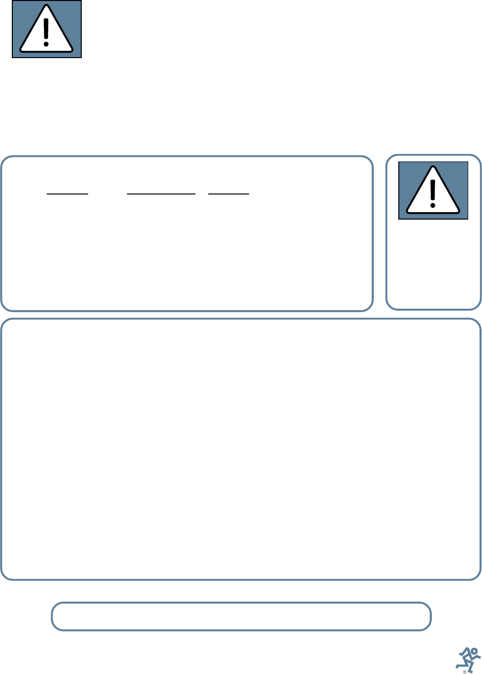
Lend Me Your Ears
Exposure to extremely
high noise levels may cause
permanent hearing loss. In-
dividuals vary considerably
in susceptibility to noise-
induced hearing loss, but nearly everyone
will lose some hearing if exposed to suffi-
ciently intense noise for a period of time.
The U.S. Government’s Occupational
Safety and Health Administration (OSHA)
has specified the permissible noise level ex-
posures shown in this chart.
According to OSHA, any exposure in ex-
cess of these permissible limits could result
in some hearing loss. To ensure against po-
tentially dangerous exposure to high
sound-pressure levels, it is recommended
that all persons exposed to equipment ca-
pable of producing these levels use hearing
protectors while this unit is in operation.
Ear plugs or protectors in the ear canals or
over the ears must be worn when operating
this amplification system in order to pre-
vent a permanent hearing loss if exposure is
in excess of the limits set forth here.
Contents
SAFETY INSTRUCTIONS .............................................................................................................2
INTRODUCTION ...........................................................................................................................4
REAR PANEL DESCRIPTION ........................................................................................................4
HOOKUP DIAGRAM .....................................................................................................................5
CONNECTIONS ............................................................................................................................5
PLACEMENT .................................................................................................................................6
AC POWER ...................................................................................................................................6
THERMAL CONSIDERATIONS .....................................................................................................6
SERVICE INFORMATION .............................................................................................................7
Warranty Service .......................................................................................................
7
Troubleshooting..........................................................................................................
7
Repair ....................................................................................................................... 8
CARE AND MAINTENANCE .........................................................................................................8
SA1521 SPECIFICATIONS ...........................................................................................................9
Architects and Engineers’ Specifications .....................................................................
10
FREQUENCY RESPONSE GRAPH ..............................................................................................10
SA1521 LIMITED WARRANTY ...................................................................................................11
Don’t forget to visit our website at www.mackie.com
for more information about this and other Mackie products.
Duration Per Day Sound Level dBA, Typical
In Hours Slow Response Example
8 90 Duo in small club
692
4 95 Subway Train
397
2 100 Very loud classical music
1.5 102
1 105 Tami screaming at Adrian about deadlines
0.5 110
0.25 or less 115 Loudest parts at a rock concert
The SA1521
can produce a
maximum SPL of
133 dB @ 1m
Part No. 820-262-00 Rev. C 11/03
© 2003 LOUD Technologies Inc. All Rights Reserved.
4
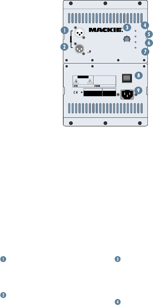
REAR PANEL DESCRIPTION
MAIN INPUT
This is a female XLR-type connector that
accepts a balanced line-level signal from a
mixing console or other signal source.
LOOP OUT
This is a male XLR-type connector that
produces exactly the same signal that is
connected to the
MAIN INPUT
jack. Use it
to daisy-chain several SA1521s together off
the same signal source.
INTRODUCTION
the high phase shift characteristics of large
diameter woofers.
More importantly, the amplifier incorpo-
rates the high-voltage output required to
generate extreme SPL levels. The SA1521
also features a low-distortion, high-output
horn design. This was developed to provide
the correct power response and phase
alignment characteristics
at the crossover frequency.
Ultra-wide, controlled
dispersion performance
continues to be one of
Mackie Designs’ most
important engineering
goals for sound reinforce-
ment enclosures. With the
resulting 75º x 65º disper-
sion pattern, the SA1521
provides very open, natural
sound reproduction at
extreme output levels.
The rear mounted am-
plifier assembly features
separate signal and AC
power panels separated by
a large aluminum heatsink. The signal in-
put panel contains:
• an input XLR and loop through XLR
• a volume level control
• Power On indicator
• Signal Present indicator
• Limit indicator
• Thermal protection indicator
The system accepts a standard line-level
signal via an XLR input connector.
The SA1521 cabinet is constructed using
both multi-layered plywood and pressure-
injected structural resin caps. The top and
bottom sections both have handles for easy
movement and relocation.
Level Control
This controls the overall signal level at the
input to the built-in power amplifiers. This
control ranges from –15 dB to +5 dB of
gain. The center detent is 0 dB (unity gain).
Power ON Indicator
When the power switch is turned on,
and the linecord is connected to an active
AC power supply, this indicator lights green
to let you know that you’re ready to rock
and roll. The cool blue LED on the front of
the cabinet works in the same way.
Thank you for choosing a Mackie active
sound reinforcement speaker system.
The SA1521 is a high-efficiency, extreme
output, active two-way, wide dispersion,
sound reinforcement speaker system. The
SA1521 benefits from the integration of
500 watts of amplifier power, complete active
control electronics, and RCF Precision com-
ponents. These elements
together form a speaker
system with 100 dB of
sensitivity (@ 1 watt/
1 meter). The result is
unprecedented output,
resolution and clarity.
The components
inside the SA1521
incorporate several state
of the art advancements
in transducer technology.
These advancements
have been in develop-
ment for over two years.
The compression driver
is a new 1.75-inch
titanium diaphragm
design. It features a 3-slot, low-distortion
geometry phase plug. The amplifier for the
compression driver incorporates a Class AB
topology renowned for its clarity and warmth.
The low-frequency amplifier features an
innovative Class G hybrid topology. By
incorporating a high-frequency switcher
into the amplifier power supply design and
focusing the design effort into generating
the best possible “application-specific”
amplifier design, we arrived at a high-
efficiency amplifier that delivers 400 watts
RMS (continuous), and 600 watts peak at
100 Hz. It’s quite capable of dealing with
WARNING:
THIS SURFACE MAY REACH HIGH TEMPERATURE DURING
STANDARD USE. TO ENSURE PROPER OPERATION ALLOW A MINIMUM OF 6 INS.
OF CLEARANCE FROM THIS SURFACE AND ADEQUATE VENTILATION. TO REDUCE
THE RISK OF ELECTRIC SHOCK DO NOT REMOVE THIS PANEL OR ANY ATTACHED
COMPONENT. NO OPERATOR SERVICEABLE PARTS INSIDE. REFER SERVICING TO
QUALIFIED PERSONNEL. TO REDUCE THE RISK OF FIRE OR ELECTRIC SHOCK, DO NOT
EXPOSE THIS APPLIANCE TO RAIN OR MOISTURE.
RISK OF ELECTRIC SHOCK
DO NOT OPEN
REPLACE WITH THE SAME TYPE FUSE AND RATING.
DISCONNECT SUPPLY CORD BEFORE CHANGING FUSE
UTILISE UN FUSIBLE DE RECHANGE DE MÊME TYPE.
DEBRANCHER AVANT DE REMPLACER LE FUSIBLE
CAUTION
AVIS:
RISQUE DE CHOC ELECTRIQUE — NE PAS OUVRIR
SERIAL NUMBER MANUFACTURING DATE
ON
POWER
THERMAL
SIGNAL
LIMIT
LOOP OUT
MAIN INPUT
PARALLEL
0dB
-15 +5
SA1521
CONCEIVED AND DESIGNED BY MACKIE DESIGNS INC, WOODINVILLE, WA, USA
AND MACKIE EUROPE • COPYRIGHT ©2001 •
THE FOLLOWING ARE TRADEMARKS OR REGISTERED TRADEMARKS OF MACKIE DESIGNS INC.:
"MACKIE", AND THE "RUNNING MAN" FIGURE • PATENT PENDING
ACTIVE SOUND REINFORCEMENT
SPEAKER SYSTEM
5
SIGNAL Present Indicator
This LED illuminates whenever there is
a signal present at the
MAIN INPUT
connec-
tor on the rear panel. It senses the signal
just after the Level control, so if the Level
control is turned down, the
SIGNAL
Present
indicator turns off.
LIMIT Indicator
The SA1521 has a built-in limiter that
prevents the amplifier outputs from clip-
ping or overdriving the transducers. The
LIMIT
indicator lights when the limiter is
activated. It’s okay for the
LIMIT
indicator
to blink occasionally, but if it blinks fre-
quently or lights continuously, turn down
the level control until the
LIMIT
indicator
only blinks occasionally.
THERMAL Indicator
There is also a thermal protection circuit
that monitors the internal temperature of
HOOKUP DIAGRAM
1202-VLZPRO
WARNING :
THIS SURFACE MAY REACH HIGH TEMPERATURE DURING
STANDARD USE. TO ENSURE PROPER OPERATION ALLOW A MINIMUM OF 6 INS.
OF CLEARANCE FROM THIS SURFACE AND ADEQUATE VENTILATION. TO REDUCE
THE RISK OF ELECTRIC SHOCK DO NOT REMOVE THIS PANEL OR ANY ATTACHED
COMPONENT. NO OPERATOR SERVICEABLE PARTS INSIDE. REFER SERVICING TO
QUALIFIED PERSONNEL. TO REDUCE THE RISK OF FIRE OR ELECTRIC SHOCK, DO NOT
EXPOSE THIS APPLIANCE TO RAIN OR MOISTURE.
RISK OF ELECTRIC SHOCK
DO NOT OPEN
REPLACE WITH THE SAME TYPE FUSE AND RATING.
DISCONNECT SUPPLY CORD BEFORE CHANGING FUSE
UTILISE UN FUSIBLE DE RECHANGE DE MÊME TYPE.
DEBRANCHER AVANT DE REMPLACER LE FUSIBLE
CAUTION
AVIS:
RISQUE DE CHOC ELECTRIQUE — NE PAS OUVRIR
SERIAL NUMBER MANUFACTURING DATE
ON
POWER
115V AC FUSE AC125V-T6.3A
POWER
THERMAL
SIGNAL
LIMIT
LOOP OUT
MAIN INPUT
PARALLEL
0dB
-15 +5
SA1521
CONCEIVED AND DESIGNED BY MACKIE DESIGNS INC, WOODINVILLE, WA, USA
AND MACKIE EUROPE • COPYRIGHT ©2001 •
THE FOLLOWING ARE TRADEMARKS OR REGISTERED TRADEMARKS OF MACKIE DESIGNS INC.:
"MACKIE", AND THE "RUNNING MAN" FIGURE • PATENT PENDING
ACTIVE SOUND REINFORCEMENT
SPEAKER SYSTEM
WARNING:
THIS SURFACE MAY REACH HIGH TEMPERATURE DURING
STANDARD USE. TO ENSURE PROPER OPERATION ALLOW A MINIMUM OF 6 INS.
OF CLEARANCE FROM THIS SURFACE AND ADEQUATE VENTILATION. TO REDUCE
THE RISK OF ELECTRIC SHOCK DO NOT REMOVE THIS PANEL OR ANY ATTACHED
COMPONENT. NO OPERATOR SERVICEABLE PARTS INSIDE. REFER SERVICING TO
QUALIFIED PERSONNEL. TO REDUCE THE RISK OF FIRE OR ELECTRIC SHOCK, DO NOT
EXPOSE THIS APPLIANCE TO RAIN OR MOISTURE.
RISK OF ELECTRIC SHOCK
DO NOT OPEN
REPLACE WITH THE SAME TYPE FUSE AND RATING.
DISCONNECT SUPPLY CORD BEFORE CHANGING FUSE
UTILISE UN FUSIBLE DE RECHANGE DE MÊME TYPE.
DEBRANCHER AVANT DE REMPLACER LE FUSIBLE
CAUTION
AVIS:
RISQUE DE CHOC ELECTRIQUE — NE PAS OUVRIR
SERIAL NUMBER MANUFACTURING DATE
ON
POWER
115V AC FUSE AC125V-T6.3A
POWER
THERMAL
SIGNAL
LIMIT
LOOP OUT
MAIN INPUT
PARALLEL
0dB
-15 +5
SA1521
CONCEIVED AND DESIGNED BY MACKIE DESIGNS INC, WOODINVILLE, WA, USA
AND MACKIE EUROPE • COPYRIGHT ©2001 •
THE FOLLOWING ARE TRADEMARKS OR REGISTERED TRADEMARKS OF MACKIE DESIGNS INC.:
"MACKIE", AND THE "RUNNING MAN" FIGURE • PATENT PENDING
ACTIVE SOUND REINFORCEMENT
SPEAKER SYSTEM
WARNING :
THIS SURFACE MAY REACH HIGH TEMPERATURE DURING
STANDARD USE. TO ENSURE PROPER OPERATION ALLOW A MINIMUM OF 6 INS.
OF CLEARANCE FROM THIS SURFACE AND ADEQUATE VENTILATION. TO REDUCE
THE RISK OF ELECTRIC SHOCK DO NOT REMOVE THIS PANEL OR ANY ATTACHED
COMPONENT. NO OPERATOR SERVICEABLE PARTS INSIDE. REFER SERVICING TO
QUALIFIED PERSONNEL. TO REDUCE THE RISK OF FIRE OR ELECTRIC SHOCK, DO NOT
EXPOSE THIS APPLIANCE TO RAIN OR MOISTURE.
RISK OF ELECTRIC SHOCK
DO NOT OPEN
REPLACE WITH THE SAME TYPE FUSE AND RATING.
DISCONNECT SUPPLY CORD BEFORE CHANGING FUSE
UTILISE UN FUSIBLE DE RECHANGE DE MÊME TYPE.
DEBRANCHER AVANT DE REMPLACER LE FUSIBLE
CAUTION
AVIS:
RISQUE DE CHOC ELECTRIQUE — NE PAS OUVRIR
SERIAL NUMBER MANUFACTURING DATE
ON
POWER
115V AC FUSE AC125V-T6.3A
POWER
THERMAL
SIGNAL
LIMIT
LOOP OUT
MAIN INPUT
PARALLEL
0dB
-15 +5
SA1521
CONCEIVED AND DESIGNED BY MACKIE DESIGNS INC, WOODINVILLE, WA, USA
AND MACKIE EUROPE • COPYRIGHT ©2001 •
THE FOLLOWING ARE TRADEMARKS OR REGISTERED TRADEMARKS OF MACKIE DESIGNS INC.:
"MACKIE", AND THE "RUNNING MAN" FIGURE • PATENT PENDING
ACTIVE SOUND REINFORCEMENT
SPEAKER SYSTEM
Mixer or
Preamplifier
Right
Line level
Output
Left
Line level
Output
To Next
Speaker
To Next
Speaker
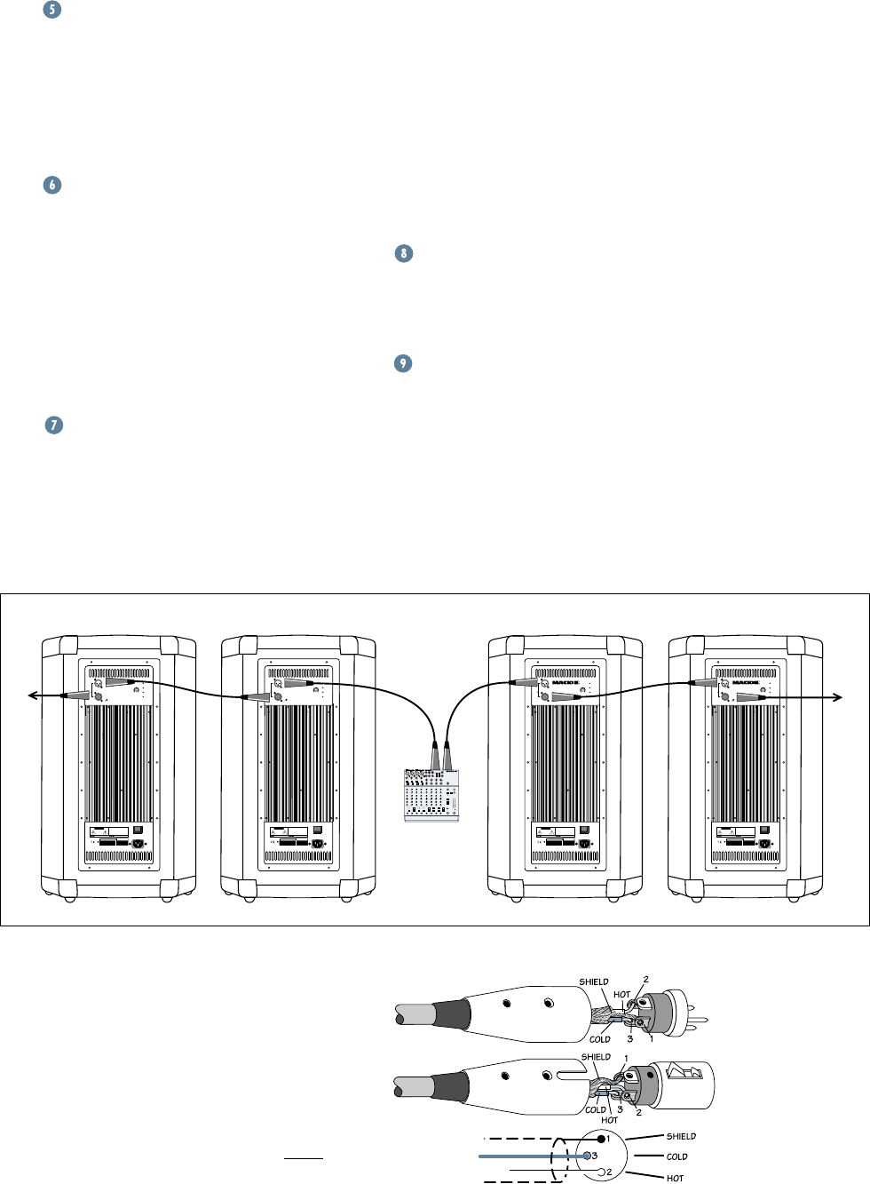
DAISY-CHAINING MULTIPLE SA1521s
the amplifiers and heatsink. If the tempera-
ture should exceed a safe operating level,
this indicator lights and the signal is muted
to allow the amplifiers to cool. When the
temperature cools to a safe level once again,
the thermal protection circuit deactivates
and normal operation continues.
Note: Activation of the thermal protection
circuit is an indication that you should take
steps to avoid continued thermal problems.
See “Thermal Considerations” on page 6.
Power Switch
Use this switch to turn the SA1521 on
and off. Make sure the level control is
turned down before you turn it on.
AC Receptacle
This is where you connect the AC linecord
to provide AC power for the built-in power am-
plifiers. Plug the linecord into an AC socket
properly configured for your particular model.
CONNECTIONS
The SA1521 has one female XLR input
that accepts a balanced line-level signal.
When connecting a balanced signal, be sure
it’s wired per AES (Audio Engineering So-
ciety) standards:
XLR
Hot (+) Pin 2
Cold (–) Pin 3
Shield (Ground) Pin 1 Balanced XLR Connectors

6
THERMAL
CONSIDERATIONS
The SA1521 has two powerful built-in
amplifiers capable of producing a combined
500 watts of power. As amplifiers produce
heat, it is important to dissipate the heat as
quickly as possible. This results in increased
reliability and longevity for the amplifier.
The amplifier module is mounted on a
large heatsink, which is cooled by convection
where cool air is drawn through it’s fins, car-
rying the heat away. In order for this
convection cooling to work efficiently, it is
important to provide adequate airspace be-
hind the loudspeaker. When you position the
SA1521, we recommend leaving at least six
inches of air space behind it.
In the unlikely event of the amplifier over-
heating, a built-in thermal switch will
activate, which mutes the signal and lights
the
THERMAL
LED. When the amplifier has
cooled down to a safe operating temperature,
the thermal switch resets itself, and the
SA1521 resumes normal operation.
If the thermal switch activates frequently,
try turning down the level control a notch or
two on the mixing console (or the back of the
SA1521) to avoid overheating the amplifier.
If the temperature in the room is too high,
it could cause the amplifier to overheat. In
this case, you should try aiming a fan at the
rear panel to move more air through the fins.
age specified for your model. If the voltage
should drop below 97% of the specified line
voltage, the built-in amplifiers will no longer
be able to supply rated power. (They will
continue to operate down to 80% of the
rated line voltage, but won’t reach full power,
resulting in lower headroom.)
Be sure the electrical service can supply
enough amperage for all the components
connected to it.
We recommend that a stiff (robust) supply
of AC power be used because the amplifiers
place high current demands on the AC line.
The more power that is available on the line,
the louder the speakers will play and the
more peak output power will be available for
cleaner, punchier bass. A suspected problem
of “poor bass performance” is often caused
by a weak AC supply to the amplifiers.
CAUTION: Never remove the ground pin
on the power cord of the SA1521 or any
other component. This is very dangerous.
There is also a male XLR connector la-
beled
LOOP OUT
. This is also wired
according to the AES standard.
The
LOOP OUT
connector allows you to
connect more than one SA1521 to your sys-
tem. Simply plug the signal source (i.e.,
mixer output) into the first
MAIN INPUT
jack, and patch that speaker’s
LOOP OUT
jack to the next
MAIN INPUT
jack, and so
on, daisy-chaining multiple speakers.
The
LOOP OUT
jack is wired straight
from the
MAIN INPUT
connector — there is
no electronic circuitry between — so the
signal coming out of the
LOOP OUT
jack is
exactly the same as the signal going in.
PLACEMENT
The SA1521 speaker is designed to sit on
the floor or stage. It can be pole-mounted via
the built-in socket on the bottom of the cabinet.
Be sure the pole is capable of supporting the
100 lbs. weight of the SA1521.
WARNING: The cabi-
net has no rigging
points and is not suit-
able for flying. NEVER
attempt to suspend the
SA1521 by its handles.
You can create a horizontal array by plac-
ing the cabinets side-by-side. However, you
should have a good understanding of the re-
lationship between the splay angle (the
angle between the facing sides of the cabi-
nets), the on-axis power, and frequency
cancellation effects between cabinets.
When two cabinets are placed side-by-
side, the actual splay angle is 20º (determined
by a 10º angle on each cabinet side). As the
splay angle increases toward the angle of
horizontal coverage (75º for the SA1521),
the on-axis power decreases, but the fre-
quency response becomes smoother as the
comb-filtering effects (caused by the interac-
tion in the area of double-coverage) decrease.
As with any powered
components, protect
them from moisture. If
you are setting them up
outdoors, make sure
they are under cover if
you expect rain.
AC POWER
Be sure the SA1521 is plugged into an
outlet that is able to supply the correct volt-
7
• Is the
THERMAL
indicator lit red on the
rear panel? Make sure there is at least six
inches of free space behind the SA1521.
Poor bass performance
• Check the polarity of the connections
between the mixer and the loudspeak-
ers. You may have your positive and
negative connections reversed at one
end of one cable, causing one loud-
speaker to be out-of-phase.
Poor sound
• Is it loud and distorted? Make sure that
you’re not overdriving a stage in the
signal chain. Verify that all level controls
are set properly.
• Is the input connector plugged com-
pletely into the jack? Be sure all
connections are secure. It’s a good idea
to periodically clean all electrical
connections with a non-lubricating
electrical contact cleaner.
Noise
• Make sure all connections to the active
loudspeakers are good and sound.
• Make sure none of the signal cables are
routed near AC cables, power trans-
formers, or other EMI-inducing devices.
• Is there a light dimmer or other SCR-
based device on the same AC circuit as
the SA1521? Use an AC line filter or
plug the SA1521 into a different AC
circuit.
Hum
• Try disconnecting the cable connected
to the
MAIN INPUT
jack. If the noise
disappears, it could be a “ground loop,”
rather than a problem with the SA1521.
Try some of the following troubleshooting
ideas:
• Use balanced connections throughout
your system for the best noise rejection.
• Whenever possible, plug all the audio
equipment’s linecords into outlets which
share a common ground. The distance
between the outlets and the common
ground should be as short as possible.
SERVICE INFORMATION
Warranty Service
If you think your loudspeaker has a
problem, please do everything you can to
confirm it before calling for service, includ-
ing reading through the following
Troubleshooting section. Doing so might
save you from being deprived of your
Mackie loudspeaker.
Of all Mackie products returned for ser-
vice (which is hardly any at all), many are
coded “CND” — Could Not Duplicate—
which usually means the problem lay some-
where else in the system. The following
troubleshooting tips may sound obvious,
but here are some things you can check:
Troubleshooting
No power
• Our favorite question: Is it plugged in?
Make sure the AC outlet is live (check
with a tester or lamp).
• Our next favorite question: Is the
POWER switch on? If not, try turning
it on.
• Is the POWER LED on the rear panel
glowing green? If not, make sure the AC
outlet is live. If so, refer to “No sound”
below.
• The internal AC line fuse may be blown.
This is not a user serviceable part. If you
suspect the AC line fuse is blown, please
see the REPAIR section next.
No sound
• Is the input LEVEL control for the
input source turned all the way down?
Verify that all the volume controls in the
system are properly adjusted.
• Is the signal source working (and making
union scale)? Make sure the connecting
cables are in good repair and securely
connected at both ends. Make sure the
output volume (gain) control on the
mixing console is turned up sufficiently
to drive the inputs of the speaker.
• Make sure the mixer does not have a
Mute on or a Processor loop engaged. If
you find something like this, make sure
the volume/gain is turned down before
disengaging the offending switch.

8
CARE AND MAINTENANCE
environment, warm up the voice coils
slowly by sending a low-level signal
through them for about 15 minutes
prior to high-power operation.
• Use a slighty damp cloth with a mild
soap solution to clean the cabinets. Only
do this when the power is turned off.
Avoid getting moisture into any of the
openings of the cabinet, particularly
where the drivers and amplifier assem-
bly are located.
Repair
Service for the SA1521 is available only
from one of our authorized domestic ser-
vice stations or at the factory service center
located in Whitinsville, Massachusetts.
Service outside the United States can be ob-
tained through local dealers or distributors.
If your SA1521 needs service, please fol-
low these instructions:
1. Review the preceding troubleshooting
suggestions. Please.
2. Call Mackie Tech Support at 1-800-
898-3211, 7 AM to 5 PM PST, to
explain the problem in detail. They will
ask you all sorts of impertinent ques-
tions in the hope of sorting out the
problem. If it appears that the SA1521
needs repair, request an RA (Return
Authorization) number. Have your
loudspeaker’s serial number ready. You
must have an RA number before you
can obtain service at the factory or an
authorized service center.
3. Keep this user’s manual and the detach-
able linecord. We don’t need them to
repair the loudspeaker.
4. Pack the loudspeaker in its original
packaging, including protective wrap,
endcaps, and box. This is very impor-
tant. When you call for the RA number,
please let Tech Support know if you
need new packaging. LOUD Technolo-
gies is not responsible for any damage
that occurs due to non-factory packaging.
5. Include a legible note stating your name,
shipping address (no P.O. boxes),
daytime phone number, RA number,
and a detailed description of the prob-
lem, including how we can duplicate it.
6. Write the RA number in BIG PRINT
on top of the box.
7. Ship the loudspeaker to us. We suggest
insurance for all forms of cartage. Ship
to this address:
MACKIE
SERVICE DEPARTMENT
Building #11
One Main Street
Whitinsville, MA 01588
8. We’ll try to fix the loudspeaker in three
to five business days. Ask Tech Support
for current turnaround times when you
call for your RA number. The product
MUST be packaged in its original
packing box and have the RMA number
appear on the box. Once it is repaired,
we’ll ship it back to you the same way in
which it was received. This paragraph
does not necessarily apply to non-
warranty service.
Your Mackie loudspeak-
ers will provide many
years of reliable service
if you follow these
guidelines:
• Avoid exposing the loudspeakers to
moisture. If they are set up outdoors, be
sure they are under cover if you expect
rain.
• Avoid exposure to extreme cold (below
freezing temperatures). If you must
operate the loudspeakers in a cold

9
SA1521 SPECIFICATIONS
System Specifications
Frequency Range (–10 dB):
49 Hz–20 kHz
Frequency Response (–3 dB):
57 Hz–18 kHz
Horz. Coverage Angle (–6 dB):
75° averaged 1 kHz to 6 kHz
Vert. Coverage Angle (–6 dB):
65° averaged 1 kHz to 6 kHz
Sensitivity (1W@1m):
100 dB
Maximum SPL Long-term:
130 dB @ 1m
Maximum SPL Peak:
133 dB @ 1m
Crossover Point:
1300 Hz
Transducers
Low Frequency
Diameter: 15 in/381mm
High Frequency
Diaphragm Diameter: 1.75 in/44mm
Diaphragm Material: Titanium
Exit Throat: 1.00 in/28.4mm
Horn
Type: Constant Directivity
Mouth Size: 10.6˝ x 10.6˝
(27 x 27 cm)
Throat Size: 1.0˝ (2.54 cm)
Volume Control
Rotating Knob: –15 to +5 dB
(0 dB detent)
Amplifiers
Low Frequency:
Rated Output*: 400 watts RMS
continuous
Rated THD: <0.03%
Design: Class G, High Efficiency/
High Current
*Rated power is continuous RMS wattage into the transducer’s
rated impedance using a 100Hz sine wave.
High Frequency:
Rated Output*: 100 watts RMS
continuous
Rated THD: <0.03%
Design: Class AB
*Rated power is into the transducer’s rated impedance using a
1kHz sine wave signal.
Audio Input/Output
Main Input, Loop Out: 50kΩ impedance,
balanced
Connector Type: XLR
Line Input Power
US : 120V, 60 Hz
Recommended Amperage Service: 13 amps
AC Connector: 3 pin IEC- Male
Europe: 230V, 50 Hz
Recommended Amperage Service: 7 amps
AC Connector: 3 pin IEC-Male
Control System Functions
Electronic Crossover
Phase Alignment
Time Correction
Equalization
Electronic System protection
Thermal Overload protection
Independent High- and Low-Frequency Driver
protection
Indicator LEDs
Power On: Green LED
Signal Present: Green LED
Limit: Yellow LED
Thermal: Red LED
Safety Features
RMS Limiting:
Monitoring and limiting of continuous
RMS output of amplifiers
Thermal:
Monitoring of thermal condition of
power supply and amplifiers. High
temperature condition engages input-
stage shut down and autoreset function.
Physical
Enclosure:
Trapezoidal, 10° side angles, 18mm
multi-layered plywood, top and bottom
high-pressure resin injected “caps”
Handles:
One on top, one on bottom cap; one
three-piece handle on each side
Color:
Black, PVC coated finish
Grille:
Custom perforated oval steel grille with
anti-corrosive treatment
Mounting Methods:
Floor mount only—not suitable for flying
Pole-mountable via built-in socket on bottom
Dimensions
Height: 32.0 in/81.3 cm
Front Width: 19.1 in/48.5 cm
Rear Width: 13.9 in/35.3 cm
Depth: 18.1 in/46.0 cm
Net Weight: 101.0 lb/45.8 kg
Disclaimer
Since we are always striving to make our prod-
ucts better by incorporating new and improved
materials, components, and manufacturing meth
ods, we reserve the right to change these specifica-
tions at any time without notice.
“Mackie.” and the “Running Man” figure are
registered trademarks of LOUD Technologies Inc.
All other brand names mentioned are trade-
marks or registered trademarks of their respective
holders, and are hereby acknowledged.
©2003 LOUD Technologies Inc.
All Rights Reserved.
10
Architects and Engineers’ Specifications
Thermal protection shall be provided by
a thermal sensor mounted on the heatsink,
which monitors the heatsink temperature
and triggers the thermal protection circuit
should the temperature exceed 140º F
(60º C). The thermal LED shall light and
the input signal shall be muted until the
heatsink cools to a safe operating level, at
which point the thermal protection circuit
auto-resets and normal operation resumes.
Overload protection shall be provided by
a limiter circuit, which monitors the low-
frequency amplifier output and reduces the
input level to the amplifier should the am-
plifier output begin to clip.
The loudspeaker enclosure shall have a
trapezoidal shape and shall incorporate two
side handles and a top and bottom relocation
handle. The enclosure shall be constructed
of a combination multi-ply wood and high-
pressure injected structural resin, with a black
PVC vinyl finish. The front of the loudspeaker
shall be covered with a powder coated,
weather-resistant perforated steel grille.
The active two-way full-range loudspeaker
system shall be a Mackie SA1521.
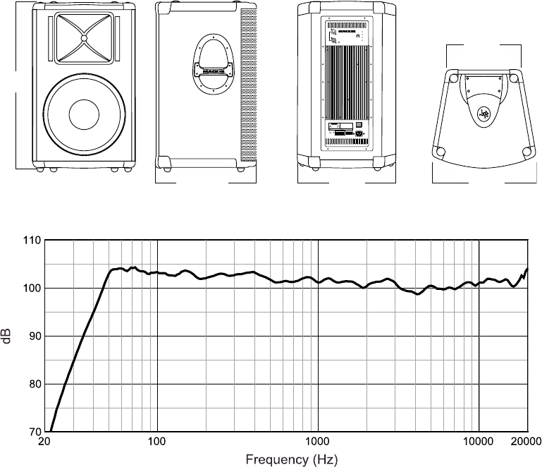
Dimensions
32.0 in/
81.3 cm
13.9 in/
35.3 cm
18.1 in/
46.0 cm
19.1 in/
48.5 cm
19.1 in/
48.5 cm
WARNING:
THIS SURFACE MAY REACH HIGH TEMPERATURE DURING
STANDARD USE. TO ENSURE PROPER OPERATION ALLOW A MINIMUM OF 6 INS.
OF CLEARANCE FROM THIS SURFACE AND ADEQUATE VENTILATION. TO REDUCE
THE RISK OF ELECTRIC SHOCK DO NOT REMOVE THIS PANEL OR ANY ATTACHED
COMPONENT. NO OPERATOR SERVICEABLE PARTS INSIDE. REFER SERVICING TO
QUALIFIED PERSONNEL. TO REDUCE THE RISK OF FIRE OR ELECTRIC SHOCK, DO NOT
EXPOSE THIS APPLIANCE TO RAIN OR MOISTURE.
RISK OF ELECTRIC SHOCK
DO NOT OPEN
REPLACE WITH THE SAME TYPE FUSE AND RATING.
DISCONNECT SUPPLY CORD BEFORE CHANGING FUSE
UTILISE UN FUSIBLE DE RECHANGE DE MÊME TYPE.
DEBRANCHER AVANT DE REMPLACER LE FUSIBLE
CAUTION
AVIS:
RISQUE DE CHOC ELECTRIQUE — NE PAS OUVRIR
SERIAL NUMBER MANUFACTURING DATE
ON
POWER
115V AC FUSE AC125V-T6.3A
POWER
THERMAL
SIGNAL
LIMIT
LOOP OUT
MAIN INPUT
PARALLEL
0dB
-15 +5
SA1521
CONCEIVED AND DESIGNED BY MACKIE DESIGNS INC, WOODINVILLE, WA, USA
AND MACKIE EUROPE • COPYRIGHT ©2001 •
THE FOLLOWING ARE TRADEMARKS OR REGISTERED TRADEMARKS OF MACKIE DESIGNS INC.:
"MACKIE", AND THE "RUNNING MAN" FIGURE • PATENT PENDING
ACTIVE SOUND REINFORCEMENT
SPEAKER SYSTEM
FREQUENCY RESPONSE GRAPH
The active two-way, full-range loudspeaker
system shall incorporate one 15-inch
low-frequency (LF) transducer and a 1-inch
exit compression driver high-frequency
(HF) transducer. The LF driver shall be
mounted in a vented enclosure tuned for
optimum low-frequency response. The HF
transducer shall be loaded on a symmetrical
constant directivity horn.
The system shall have a nominal coverage
pattern of 75° (horizontal) x 65° (vertical).
System frequency response shall vary no
more than ±3 dB from 57Hz to 18kHz
measured on axis. The loudspeaker shall in-
corporate a Class G low-frequency amplifier
capable of delivering 400 watts RMS over a
frequency range of 20Hz–1300Hz. The sys-
tem shall incorporate a Class AB 100 watt
RMS amplifier specifically designed to power
the HF driver over the range of 1300Hz –
20kHz. The amplifiers shall be mounted on
an aluminum heatsink, which shall be
mounted on the rear of the speaker system,
and shall be convection cooled.

11
SA1521 LIMITED WARRANTY
4. If the Authorized Mackie Service Center is lo-
cated in another city, pack the loudspeaker in its
original shipping carton. More information on
packing can be found in the Service section of
this manual.
5. Contact the Authorized Mackie Service Center
to arrange service or bring the loudspeaker to them.
F. LOUD Technologies and Authorized Mackie Ser-
vice Centers reserve the right to inspect any
products that may be the subject of any warranty
claims before repair or replacement is carried out.
LOUD Technologies and Authorized Mackie Service
Centers may, at their option, require proof of the
original date of purchase in the form of a dated copy
of the original dealer’s invoice or sales receipt. Final
determination of warranty coverage lies solely with
LOUD Technologies or its Authorized Service Centers.
G. Mackie loudspeakers returned to LOUD Tech-
nologies and deemed eligible for repair or
replacement under the terms of this warranty will be
repaired or replaced within thirty days of receipt by
LOUD Technologies. LOUD Technologies may use
refurbished parts for repair or replacement of any
product. Products returned to LOUD Technologies
that do not meet the terms of this Warranty will be
repaired and returned C.O.D. with billing for labor,
materials, return freight, and insurance. Products re-
paired under warranty at the factory will be returned
freight prepaid by LOUD Technologies to any loca-
tion within the boundaries of the USA.
H. LOUD Technologies warrants all repairs per-
formed on Mackie products for 90 days or for the
remainder of the original warranty period. LOUD
Technologies assumes no responsibility for the qual-
ity or timeliness of repairs performed by Authorized
Mackie Service Centers.
I. This warranty is extended to the original purchaser
and to anyone who may subsequently purchase this
product within the applicable warranty period.
J. This is your sole warranty. LOUD Technologies
does not authorize any third party, including any
dealer or sales representative, to assume any liability
on behalf of LOUD Technologies or to make any
warranty for LOUD Technologies Inc.
K. THE WARRANTY GIVEN ON THIS PAGE IS THE
SOLE WARRANTY GIVEN BY LOUD TECHNOLOGIES
AND IS IN LIEU OF ALL OTHER WARRANTIES,
EXPRESS AND IMPLIED, INCLUDING THE
WARRANTIES OF MERCHANTABILITY AND
FITNESS FOR A PARTICULAR PURPOSE. THE
WARRANTY GIVEN ON THIS PAGE SHALL BE
STRICTLY LIMITED IN DURATION TO FIVE YEARS
FROM THE DATE OF ORIGINAL PURCHASE FROM
AN AUTHORIZED MACKIE DEALER. UPON
EXPIRATION OF THE APPLICABLE WARRANTY
PERIOD, LOUD TECHNOLOGIES INC. SHALL
HAVE NO FURTHER WARRANTY OBLIGATION
OF ANY KIND. LOUD TECHNOLOGIES INC.
SHALL NOT BE LIABLE FOR ANY INCIDENTAL,
SPECIAL, OR CONSEQUENTIAL DAMAGES
THAT MAY RESULT FROM ANY DEFECT IN THE
MACKIE PRODUCT OR ANY WARRANTY CLAIM.
Some states do not allow exclusion or limitation
of incidental, special, or consequential damages
or a limitation on how long warranties last, so
some of the above limitations and exclusions may
not apply to you. This warranty provides specific
legal rights and you may have other rights which
vary from state to state.
Please keep your sales receipt in a safe place.
A. LOUD Technologies Inc. warrants all materials,
workmanship and proper operation of this Mackie
SA1521 for a period of five years from the original
date of purchase, with the following exception:
warranty on all its loudspeaker components includ-
ing woofers and compression drivers are only
warranted for two years. If any defects are found in
the materials or workmanship or if the product fails
to function properly during the applicable warranty
period, LOUD Technologies, at its option, will repair
or replace the product. This warranty applies only
to equipment sold and delivered within the U.S. by
LOUD Technologies Inc. or its authorized dealers.
B. Failure to register online or return the product
registration card will not void the five-year warranty.
C. Service and repairs of Mackie products are to be
performed only at the factory (see D below) OR at
an Authorized Mackie Service Center (see E below).
Unauthorized service, repairs, or modification will
void this warranty.
D. To obtain factory service:
1. Call Mackie Service at 800/898-3211, 7 AM
to 5 PM Monday through Friday (Pacific Time)
to get a Return Authorization (RA). Products re-
turned without an RA number will be refused.
2. Pack the SA1521 in its original shipping car-
ton. If you do not have the carton, just ask for
one when you get your RA number, and we’ll
send a shipping carton out promptly. More infor-
mation on packing can be found in the Service
section of this manual. Also include a note ex-
plaining exactly how to duplicate the problem, a
copy of the sales receipt with price and date
showing, and your return street address (no P.O.
boxes or route numbers, please!). If we cannot
duplicate the problem or establish the starting
date of your Limited Warranty, we may, at our
option, charge for service time.
3. Ship the product in its original shipping car-
ton, freight prepaid to:
MACKIE
SERVICE DEPARTMENT
One Main Street
Whitinsville, MA, 01588, USA
IMPORTANT: Make sure that the RA number is
plainly written on the shipping carton.
E. To obtain service from an Authorized Mackie
Service Center:
1. Call Mackie Service at 800/898-3211, 7 AM
to 5 PM Monday through Friday (Pacific Time)
to get: 1) The name and address of your nearest
Authorized Mackie Service Center and 2) A re-
turn authorization (RA). You must have an RA
number before taking your unit to a service
center.
2. Make sure that you have a copy of your
loudspeaker’s sales receipt from the store where
you bought the product. It is necessary to establish
purchase date and thus determine whether or not
your loudspeaker is still under warranty. If you can’t
find it, the Authorized Service Center may charge
you for repairs even if your loudspeaker is still
covered by the Five-Year Limited Warranty.
3. Make sure that the problem can be duplicated.
If you bring your loudspeaker to an Authorized
Service Center and they can’t find anything
wrong with it, you may be charged a service fee.