Mackie ProFX8 User Manual To The 8ef85fa6 8e1f 47c2 892d D064df8edfa6
User Manual: Mackie ProFX8 to the manual
Open the PDF directly: View PDF ![]() .
.
Page Count: 36
- Front Cover
- Important Safety Instructions
- Read This Page!
- Introduction
- Contents
- HOOKUP DIAGRAMS
- Rear Panel Features
- Front Panel Features
- Connection Section
- Channel Controls
- Master Controls
- 32. PHANTOM POWER SWITCH
- 33. POWER LED
- 34. METERS
- 35. BREAK SWITCH
- 36. TAPE LEVEL
- 37. STEREO GRAPHIC EQ
- 38. MAIN MIX/MON
- 39. EQ IN/BYPASS
- 40. USB INPUT LEVEL
- 41. USB THRU
- 42. PHONES LEVEL
- 43. OL LED (for stereo returns)
- 44. MUTE (for stereo returns)
- 45. STEREO RETURN FADER
- 46. FX RETURN FADER
- 47. MONITOR FADER
- 48. MAIN FADER
- Stereo Effects Processor
- Appendix A: Service Information
- Appendix B: Connections
- Appendix C: Technical Information
- Appendix D: USB interface
- ProFX8 and ProFX12 Limited Warranty
- Rear Cover
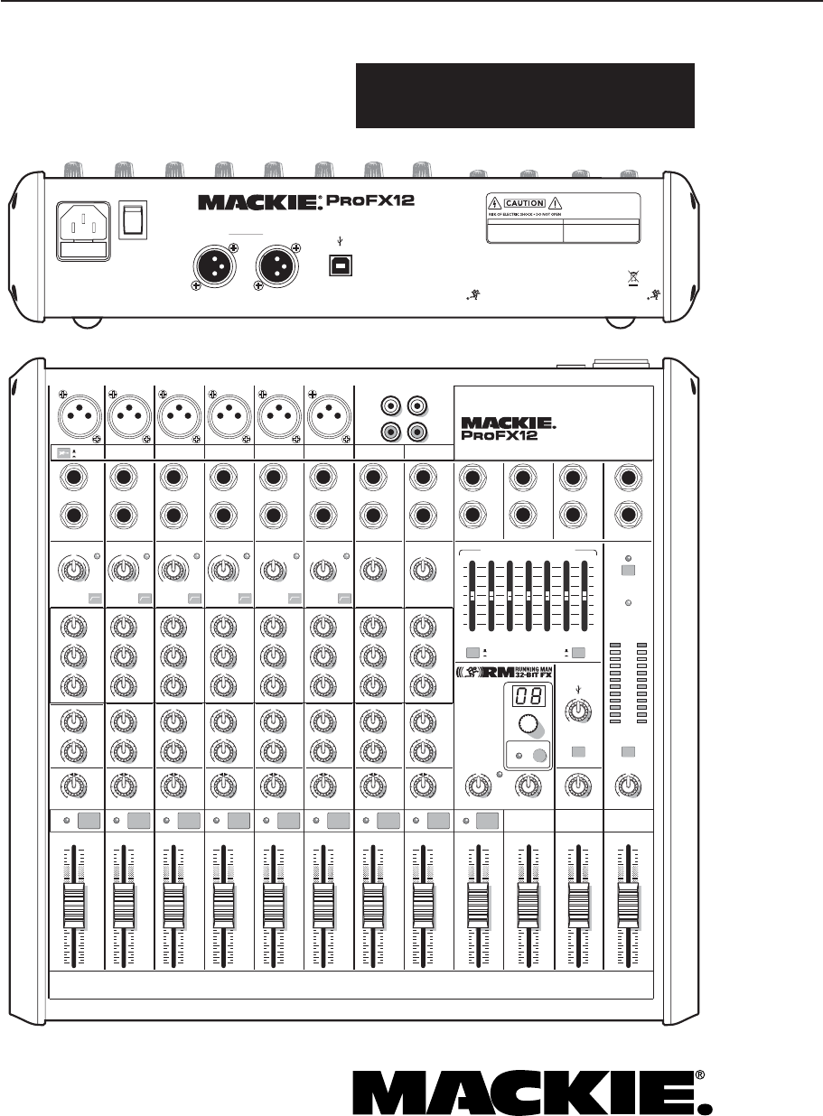
ProFX8 and ProFX12
OWNER’S MANUAL
Professional Mic/Line Mixers with FX and USB I/O
MAIN
RIGHT
(BALANCED)
MAIN
LEFT
USB
(BALANCED)
8K4K2K1K500250125
15
15
10
10
5
5
0
15
15
10
10
5
5
0
TAPE
IN
ST RETURN MAIN OUT PHONES
FOOTSWITCH
PHONES
TAPE
OUT
L
R
L
(UNBALANCED)
R
STEREO GRAPHIC EQ
DESIGNED BY MACKOIDS IN WOODINVILLE, WA, USA • MANUFACTURED IN CHINA
FABRIQUE EN CHINE • COPYRIGHT ©2008 • "MACKIE" AND THE RUNNING MAN FIGURE
ARE TRADEMARKS OF LOUD TECHNOLOGIES, INC. • PATENT PENDING.
FX SEND
MID
2.5kHz
MID
2.5kHz
MID
2.5kHz
MID
2.5kHz
MID
2.5kHz
80Hz
LOW
U
+15-15
U
+15-15
U
+15-15
LINE IN 4
INSERT
RL
LOW CUT
100 Hz
U
GAIN
M
I
C
G
A
I
N
U+50
-20dB +30dB
4
12kHz
HI
MID
2.5kHz
80Hz
LOW
U
+15-15
U
+15-15
U
+15-15
12kHz
HI
MID
2.5kHz
80Hz
LOW
U
+15-15
U
+15-15
U
+15-15
12kHz
HI
MID
2.5kHz
80Hz
LOW
U
+15-15
U
+15-15
U
+15-15
12kHz
HI
PAN
AUX
U
+15
OO
MON
FX
U
+15
OO
RL
PAN
AUX
U
+15
OO
MON
FX
U
+15
OO
RL
PAN
AUX
U
+15
OO
MON
FX
U
+15
OO
RL
PAN
AUX
U
+15
OO
MON
FX
U
+15
OO
80Hz
LOW
U
+15-15
U
+15-15
U
+15-15
RL
LOW CUT
100 Hz
12kHz
HI
PAN
AUX
U
+15
OO
MON
FX
U
+15
OO
80Hz
LOW
U
+15-15
U
+15-15
U
+15-15
BAL /
UNBAL
(MONO) (MONO) (MONO) (MONO)
LINE IN 7
LINE IN 8
BAL /
UNBAL LINE IN 9
RL
LOW CUT
100 Hz
GAIN
7/85/6
12kHz
HI
PAN
AUX
U
+15
OO
MON
FX
U
+15
OO
80Hz
LOW
U
+15-15
U
+15-15
U
+15-15
RL
M
I
C
G
A
I
N
U+50
GAIN
M
I
C
G
A
I
N
U+50
9/10
12kHz
HI
LEVEL
SET
LEVEL
SET
LEVEL
SET
LOW CUT
100 Hz
U
GAIN
M
I
C
G
A
I
N
U+50
-20dB +30dB
LEVEL
SET
LEVEL
SET
LEVEL
SET
LOW CUT
100 Hz
U
GAIN
M
I
C
G
A
I
N
U+50
-20dB +30dB
LOW CUT
100 Hz
U
GAIN
M
I
C
G
A
I
N
U+50
-20dB +30dB
PAN
AUX
U
+15
OO
MON
FX
U
+15
OO
GAIN
MIC MIC MIC MIC MIC MIC
80Hz
LOW
U
+15-15
U
+15-15
U
+15-15
U
+20-20
GAIN
U
+20-20
RL
11/12 ST RTN FX RTN
EQEQEQEQ EQ EQ EQ EQ
12kHz
HI
PAN
AUX
U
+15
OO
MON
FX
U
+15
OO
U
+15
FX TO MON
FX MASTER
U
+15
OO
OO
dB
30
20
10
10
OO
40
50
5
5
U
60
dB
30
20
10
10
OO
40
50
5
5
U
60
dB
30
20
10
10
OO
40
50
5
5
U
60
dB
30
20
10
10
OO
40
50
5
5
U
60
dB
30
20
10
10
OO
40
50
5
5
U
60
dB
30
20
10
10
OO
40
50
5
5
U
60
dB
30
20
10
10
OO
40
50
5
5
U
60
dB
30
20
10
10
OO
40
50
5
5
U
60
dB
30
20
10
10
OO
40
50
5
5
U
60
dB
30
20
10
10
OO
40
50
5
5
U
60
dB
30
20
10
10
OO
40
50
5
5
U
60
dB
30
20
10
10
OO
40
50
5
5
U
60
L
R
(MONO)
LINE IN 5
LINE IN 6
BAL /
UNBAL
L
R
LINE IN 10
BAL /
UNBAL
L
R
LINE IN 11
LINE IN 12
BAL /
UNBAL
L
R
BAL /
UNBAL
L
R
BAL /
UNBAL
L
R
MON SEND
BAL /
UNBAL
BAL /
UNBAL
PRESETS
FX PRESETS
01 BRIGHT ROOM
02 WARM LOUNGE
03 SMALL STAGE
04 WARM THEATER
05 WARM HALL
06 CONCERT HALL
13 DELAY 1 (300ms)
14 DELAY 2 (380ms)
15 DELAY 3 (480ms)
16 REVERB + DLY (250ms)
07 PLATE REVERB
08 CATHEDRAL
09 CHORUS
10 CHORUS + REV
11 DOUBLER
12 TAPE SLAP
MON MAIN
4
LINE IN 3
INSERT
3
BAL /
UNBAL
3
LINE IN 2
INSERT
2
BAL /
UNBAL
BAL /
UNBAL
2
LINE/HI-Z IN 1
INSERT
1 5/6 7/8 9/10 11/12
POWER
ON
0dB=0dBu
MAIN
METERS
OL
4
6
3
10
15
7
10
20
30
0
2
BREAK
(MUTES ALL CHANNELS)
PHANTOM
POWER
POWER
OO
+20
U
TAPE LEVEL
OO
+20
U
USB THRU
LINE
HI-Z
OO
MAX
1
OL OL OL OL OL OL OL OL OL
OL
MAIN MIX
MON
EQ IN
BYPASS
PROFESSIONAL MIC/LINE MIXER WITH FX
PROFESSIONAL MIC/LINE MIXER WITH FX
FUSE: T1.6AL AC250V
~100-240V 50/60 Hz 25W
RL
INPUT LEVEL
USB
MUTE
MUTE MUTE MUTE MUTE MUTE MUTE MUTE MUTE MUTE
48V
THIS DEVICE COMPLIES WITH PART 15 OF THE FCC RULES AND THE ICES-003 FOR
CANADA. OPERATION IS SUBJECT TO THE FOLLOWING TWO CONDITIONS: (1) THIS
DEVICE MAY NOT CAUSE HARMFUL INTERFERENCE, AND (2) THIS DEVICE MUST
ACCEPT ANY INTERFERENCE RECEIVED, INCLUDING INTERFERENCE THAT MAY
CAUSE UNDESIRED OPERATION.
MANUFACTURING DATE
SERIAL NUMBER
WARNING:
TO REDUCE THE RISK OF FIRE OR ELECTRIC
SHOCK, DO NOT EXPOSE THIS EQUIPMENT TO RAIN OR
MOISTURE. DO NOT REMOVE COVER. NO USER SERVICEABLE
PARTS INSIDE. REFER SERVICING TO QUALIFIED PERSONNEL.
AVIS:
RISQUE DE CHOC ELECTRIQUE — NE PAS OUVRIR
2
ProFX8 and ProFX12
ProFX8 and ProFX12
1. Read these instructions.
2. Keep these instructions.
3. Heed all warnings.
4. Follow all instructions.
5. Do not use this apparatus near water.
6. Clean only with a dry cloth.
7. Do not block any ventilation openings. Install in accordance with the
manufacturer’s instructions.
8. Do not install near any heat sources such as radiators, heat registers,
stoves, or other apparatus (including amplifi ers) that produce heat.
9. Do not defeat the safety purpose of the polarized or grounding-type
plug. A polarized plug has two blades with one wider than the other.
A grounding-type plug has two blades and a third grounding prong.
The wide blade or the third prong are provided for your safety. If the
provided plug does not fi t into your outlet, consult an electrician for
replacement of the obsolete outlet.
10.
Do not overload wall outlets and extension cords as this can result in a
risk of fi re or electric shock.
11.
Protect the power cord from being walked on or pinched particularly at
plugs, convenience receptacles, and the point where they exit from the
apparatus.
12.
Only use attachments/accessories specifi ed by the manufacturer.
13.
Use only with a cart,
stand, tripod, bracket,
or table specifi ed
by the manufac-
turer, or sold with
the apparatus. When
a cart is used, use
caution when moving
the cart/apparatus
combination to avoid
injury from tip-over.
14.
Unplug this apparatus during lightning storms or when unused for long
periods of time.
15.
Refer all servicing to qualifi ed service personnel. Servicing is required
when the apparatus has been damaged in any way, such as power-
supply cord or plug is damaged, liquid has been spilled or objects have
fallen into the apparatus, the apparatus has been exposed to rain or
moisture, does not operate normally, or has been dropped.
16.
This apparatus shall not be exposed to dripping or splashing, and no
object fi lled with liquids, such as vases or beer glasses, shall be placed
on the apparatus.
17.
This apparatus has been designed with Class-I construction and must
be connected to a mains socket outlet with a protective earthing con-
nection (the third grounding prong).
18.
This apparatus has been equipped with an all-pole, rocker-style AC
mains power switch. This switch is located on the rear panel and
should remain readily accessible to the user.
19.
The MAINS plug or an appliance coupler is used as the disconnect
device, so the disconnect device shall remain readily operable.
20. NOTE: This equipment has been tested and found to comply with
the limits for a Class B digital device, pursuant to part 15 of the FCC
Rules. These limits are designed to provide reasonable protection
against harmful interference in a residential installation. This equip-
ment generates, uses, and can radiate radio frequency energy and, if
not installed and used in accordance with the instructions, may cause
harmful interference to radio communications. However, there is no
guarantee that interference will not occur in a particular installation. If
this equipment does cause harmful interference to radio or television
reception, which can be determined by turning the equipment off and
on, the user is encouraged to try to correct the interference by one or
more of the following measures:
• Reorient or relocate the receiving antenna.
• Increase the separation between the equipment and the
receiver.
• Connect the equipment into an outlet on a circuit different from
that to which the receiver is connected.
• Consult the dealer or an experienced radio/TV technician for
help.
CAUTION: Changes or modifi cations to this device not expressly
approved by LOUD Technologies Inc. could void the user's authority to
operate the equipment under FCC rules.
21.
This apparatus does not exceed the Class A/Class B (whichever is
applicable)
limits for radio noise emissions from digital apparatus as
set out in the radio interference regulations of the Canadian Department
of Com mu ni ca tions.
ATTENTION — Le présent appareil numérique n’émet pas de bruits
radioélectriques dépassant las limites applicables aux appareils
numériques de class A/de class B (selon le cas) prescrites dans le
réglement sur le brouillage radioélectrique édicté par les ministere des
com mu ni ca tions du Canada.
22.
Exposure to extremely high noise levels may cause permanent hearing
loss. Individuals vary considerably in susceptibility to noise-induced
hearing loss, but nearly everyone will lose some hearing if exposed to
suffi ciently intense noise for a period of time. The U.S. Government’s
Occupational Safety and Health Administration (OSHA) has specifi ed
the permissible noise level exposures shown in the following chart.
According to OSHA, any exposure in excess of these permissible limits
could result in some hearing loss. To ensure against potentially danger-
ous exposure to high sound pressure levels, it is recommended that all
persons exposed to equipment capable of producing high sound pres-
sure levels use hearing protectors while the equipment is in operation.
Ear plugs or protectors in the ear canals or over the ears must be worn
when operating the equipment in order to prevent permanent hearing
loss if exposure is in excess of the limits set forth here:
Important Safety Instructions
PORTABLE CART WARNING
Carts and stands - The
Component should be used
only with a cart or stand
that is recommended by
the manufacturer.
A Component and cart
combination should be
moved with care. Quick
stops, excessive force, and
uneven surfaces may cause
the Component and cart
combination to overturn.
CAUTION AVIS
RISK OF ELECTRIC SHOCK. DO NOT OPEN
RISQUE DE CHOC ELECTRIQUE. NE PAS OUVRIR
CAUTION: TO REDUCE THE RISK OF ELECTRIC SHOCK DO NOT REMOVE COVER (OR BACK)
NO USER-SERVICEABLE PARTS INSIDE. REFER SERVICING TO QUALIFIED PERSONNEL
ATTENTION: POUR EVITER LES RISQUES DE CHOC ELECTRIQUE, NE PAS ENLEVER LE COUVERCLE.
AUCUN ENTRETIEN DE PIECES INTERIEURES PAR L'USAGER.
CONFIER L'ENTRETIEN AU PERSONNEL QUALIFIE.
AVIS: POUR EVITER LES RISQUES D'INCENDIE OU D'ELECTROCUTION, N'EXPOSEZ PAS CET ARTICLE
A LA PLUIE OU A L'HUMIDITE
The lightning flash with arrowhead symbol within an equilateral triangle is
intended to alert the user to the presence of uninsulated "dangerous
voltage" within the product's enclosure, that may be of sufficient magnitude
to constitute a risk of electric shock to persons.
Le symbole éclair avec point de flèche à l'intérieur d'un triangle équilatéral
est utilisé pour alerter l'utilisateur de la présence à l'intérieur du coffret de
"voltage dangereux" non isolé d'ampleur suffisante pour constituer un risque
d'éléctrocution.
The exclamation point within an equilateral triangle is intended to alert the
user of the presence of important operating and maintenance (servicing)
instructions in the literature accompanying the appliance.
Le point d'exclamation à l'intérieur d'un triangle équilatéral est employé
pour alerter les utilisateurs de la présence d'instructions importantes pour le
fonctionnement et l'entretien (service) dans le livret d'instruction
accompagnant l'appareil.
WARNING — To reduce the risk of fi re or electric shock, do not
expose this apparatus to rain or moisture.
Duration,
per day in
hours
Sound Level
dBA, Slow
Response
Typical Example
8 90 Duo in small club
692
4 95 Subway Train
397
2 100 Very loud classical music
1.5 102
1 105 Dave screaming at Steve about
deadlines
0.5 110
0.25 or less 115 Loudest parts at a rock concert

3
Owner’s Manual
Owner’s Manual
Part No. SW0713 Rev. A
©2008 LOUD Technologies Inc. All Rights Reserved,
No electrons were harmed during the production of this PDF.
2. For mono channels, adjust the gain control so
the level set LED just comes on occasionally
during the loudest parts of your performance.
The mono channel gain affects the mic and the
line inputs. The hybrid channel gain affects the
mic input only, not the stereo line inputs.
The stereo channel gain adjusts the stereo line
inputs. Adjust as desired, and check the OL
LED does not come on during the loudest pas-
sages.
3. Repeat steps 1 to 2 for your other channels.
Instant Mixing
1.
To get sound out of the speakers and into a
waiting world, turn up the channel’s fader to the
U (unity gain) position,
and slowly bring up the
main fader
to a comfortable listening level.
2. Sing and play. You’re a star! Bring in the other
channels, and adjust their faders to make a
nice mix and generally have fun.
USB
The USB connection allows you to play 2 channels of
audio from your computer, and to record the main mix
to your computer. See Appendix D on page 32 for details
of getting started with the USB.
Notes
For optimum sonic performance, the channel faders
and main fader should be set near the “U” (unity gain)
markings.
Turn down all faders before making connections to
and from your ProFX mixer.
When you shut down your system, turn off your ampli-
fi ers or powered speakers fi rst. When powering up, turn
them on last. This will prevent the possibility of turn-on
and turn-off thumps heard in your speakers.
Save the shipping box! You may need it someday.
Read This Page!
You probably want to try out your new
mixer right away. Before you do, please
read the safety instructions on page 2,
then read this page, and the rest later.
Zero the Mixer
1. Turn down all knobs except the channel EQ and
pan knobs, and set all the faders fully down.
2. Set all channel EQ knobs, pan knobs, and the
graphic EQ sliders at their center detent.
3. Set all buttons to the "out" position.
4. Whistle a popular show tune.
Connections
If you already know how you want to connect the
mixer, go ahead and connect the inputs and outputs
the way you want them. If you just want to get sound
through the mixer, follow these steps:
1.
Plug signal sources into the mixer, such as:
• Microphones plugged into the mic inputs.
Engage phantom power if your mics need
it. Check the mic's user manual to be sure.
• Line-level sources such as keyboards, drum
machines, or CD players plugged into the
line-level inputs.
• A guitar plugged into channel 1, with the
line/hi-z switch pressed in.
2
. Connect cords from the main outs to your pow-
ered speakers or amplifi er.
3. Plug in the mixer’s power cord to a live AC
outlet and turn on the mixer.
4. If you have powered speakers, turn them on.
Otherwise, hook up your passive speakers to
your amp with speaker cables, and turn it on.
Adjust your powered speaker or amplifi er level
controls to however the
manufacturer recom-
mends. (This is usually all the way up.)
Set the Gain
1. Play something into an input. This could be an
instrument, you singing or speaking, or a line
level source such as a keyboard or CD player.
Be sure that the volume of the input is the
same as it would be during normal use, or you
may have to readjust the gain in the middle of a
set. You can listen with headphones if you care-
fully turn up the channel fader and headphones
level a little.
Please write your serial number here for future
reference (i.e., insurance claims, tech support,
return authorization, make dad proud, etc.)
Purchased at:
Date of purchase:

4
ProFX8 and ProFX12
ProFX8 and ProFX12
Introduction
Thank you for choosing a Mackie professional ProFX
mixer. It is equipped with our rather lovely microphone
preamps, an internal FX processor, and a USB port for
playing and recording 2 channels of audio using a com-
puter. The ProFX8 has 8 channels and the ProFX12 has
12 channels. Apart from this difference, the mixers are
identical and this manual covers both models.
At Mackie, we know what it takes to be roadworthy.
After all, our mixers have traveled all over the world,
often under the worst of conditions, and we’ve applied
what we’ve learned to the mechanical design of our
ProFX mixers.
Reliability is paramount to sound reinforcement.
That’s why our engineers have subjected our mixers to
the most rigorous and fi endish tests imaginable to fi ne-
tune the design, and extend its limits beyond those of
ordinary mixers.
Features
• The ProFX8 mixer has 8 channels (2 mono, 2
hybrid, 1 stereo)
• The ProFX12 mixer has 12 channels (4 mono, 2
hybrid, 2 stereo)
• Mono channels have a mic input and a mono
line-level input, with a gain control and level
set LED for adjustment of mic and line gain
• Hybrid channels have a mic input and stereo
line-level inputs, with a gain control and level
set LED for adjustment of mic gain
• Stereo channels have stereo line-level inputs,
with a gain control to adjust the line gain
• +48V phantom power can be applied to all mics
• Tape/CD stereo RCA inputs and outputs
• 1/4" TRS insert jacks on mono channels
• Channel 1 hi-z switch allows direct connection
of a guitar or bass without a DI box
• Low cut switch on mono and hybrid channels
• 3-band EQ on each channel
• Aux monitor control on each channel
• Aux FX control on each channel
• Each channel has a pan control, mute switch,
overload (OL) LED, and fader
• Stereo return has mute, OL LED and fader
• XLR and 1/4" TRS main stereo line outputs
• 1/4" TRS stereo return
• 1/4" TRS FX send and monitor send
• 1/4" TRS stereo headphones output
• Headphones level control
• Tape input level control
• 16 built-in Running Man effects with input
level, OL LED, preset display, FX to monitor
level, and footswitchable mute/unmute
• 7-band graphic EQ can be used for main mix, or
monitor mix, or bypassed
• 12-segment stereo output meters on main mix
• Break switch mutes all channels except tape
input and USB input
• Faders for stereo return, FX return, monitor
and main
• USB connection allows 2-channel computer
recording and 2-channel computer playback
• USB thru switch and input level
How To Use This Manual
The fi rst pages after the table of contents are the
hookup diagrams. These show typical setups for fun
times with your ProFX8 or ProFX12 mixer.
Next is a detailed tour of the entire mixer. The de-
scriptions are divided into sections, just as your mixer is
organized into distinct zones:
• Rear Panel: The AC input, power switch, XLR
line-level outputs and USB I/O
• Connection Section: The upper section, where
you connect microphones and guitars etc.
• Channel Controls: The channel strips where
you adjust and control each channel
• Master Controls: The section on the right, with
graphic EQ and main level controls
• Stereo Effect Processor
Throughout these sections you’ll fi nd illustrations
with each feature numbered and described in the
nearby paragraphs.
This icon marks infor mation that is critically
important or unique to the mixer. For your own
good, read them and remember them.
This icon will lead you to some explanations of
features and practical tips. Go ahead and skip
these if you really need to go.
Appendix A: Service information.
Appendix B: Connectors.
Appendix C: Technical information.
Appendix D: USB information.

5
Owner’s Manual
Owner’s Manual
Contents
Need help with your new mixer?
• Visit www.mackie.com and click Support to fi nd:
FAQs (Frequently Asked Questions), manuals, addendums, and
user forums.
• Email us at: techmail@mackie.com.
• Telephone 1-800-898-3211 to speak with one of our splendid
technical support representatives, (Monday through Friday,
from 7 a.m. to 5 p.m. PST).
IMPORTANT SAFETY INSTRUCTIONS ........................ 2
READ THIS PAGE! .................................................... 3
INTRODUCTION ...................................................... 4
CONTENTS ............................................................. 5
HOOKUP DIAGRAMS...............................................6
REAR PANEL FEATURES .........................................12
1. POWER CONNECTION .............................12
2. FUSE ......................................................12
3. POWER SWITCH ..................................... 12
4. XLR MAIN OUTS ................................... 12
5. USB PORT ............................................. 12
FRONT PANEL FEATURES ....................................... 13
CONNECTION SECTION ....................................... 13
6. MIC INPUTS ........................................... 13
7. LINE/HI-Z SWITCH .................................13
8. LINE/HI-Z INPUT (CHANNEL 1 ONLY) ......13
9. MONO LINE INPUTS ............................... 14
10. STEREO LINE INPUTS .............................. 14
11. CHANNEL INSERT ................................... 14
12. STEREO RETURN ....................................14
13. MON SEND ............................................ 15
14. FX SEND ................................................ 15
15. 1⁄4" MAIN OUTS .................................... 15
16. FX FOOTSWITCH .................................... 15
17. PHONES ................................................15
18. TAPE INPUT ........................................... 16
19. TAPE OUTPUTS ...................................... 16
CHANNEL CONTROLS ......................................... 17
20. GAIN ....................................................18
21. LEVEL SET LED ........................................ 18
22. LOW CUT ............................................... 18
23. HI EQ .....................................................19
24. MID EQ .................................................. 19
25. LOW EQ ................................................. 19
26. AUX MON ...............................................19
27. AUX FX ................................................... 20
28. PAN ........................................................20
29. OL LED .................................................... 20
30. MUTE .................................................... 20
31. CHANNEL FADER .....................................20
MASTER CONTROLS ........................................... 21
32. PHANTOM POWER SWITCH ..................... 21
33. POWER LED ............................................. 21
34. METERS ................................................. 21
35. BREAK SWITCH ..................................... 22
36. TAPE LEVEL ...........................................22
37. STEREO GRAPHIC EQ ............................... 22
38. MAIN MIX/MON .....................................22
39. EQ IN/BYPASS ........................................ 22
40. USB INPUT LEVEL .................................... 22
41. USB THRU.............................................. 23
42. PHONES LEVEL ....................................... 23
43. OL LED (FOR STEREO RETURNS) ..............23
44. MUTE (FOR STEREO RETURNS) ................23
45. STEREO RETURN FADER .......................... 23
46. FX RETURN FADER ................................. 23
47. MONITOR FADER ................................... 23
48. MAIN FADER .......................................... 23
STEREO EFFECTS PROCESSOR .............................24
49. PRESET DISPLAY ...................................... 24
50. PRESET SELECTOR .................................... 24
51. INTERNAL FX MUTE ................................. 24
52. FX MASTER ............................................. 24
53. OL LED ................................................... 24
54. FX TO MON ........................................... 24
APPENDIX A: SERVICE INFORMATION .................... 26
APPENDIX B: CONNECTIONS..................................27
APPENDIX C: TECHNICAL INFORMATION ................ 29
APPENDIX D: USB INTERFACE ................................32
PROFX8 AND PROFX12 LIMITED WARRANTY ........ 35
6
ProFX8 and ProFX12
ProFX8 and ProFX12
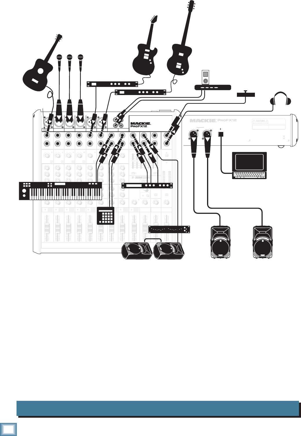
Band System ProFX12
MAIN
RIGHT
(BALANCED)
MAIN
LEFT
USB
(BALANCED)
DESIGNED BY MACKOIDS IN WOODINVILLE, WA, USA • MANUFACTURED IN CHINA
FABRIQUE EN CHINE • COPYRIGHT ©2008 • "MACKIE" AND THE RUNNING MAN FIGURE
ARE TRADEMARKS OF LOUD TECHNOLOGIES, INC. • PATENT PENDING.
POWER
ON PROFESSIONAL MIC/LINE MIXER WITH FX
FUSE: T1.6AL AC250V
~100- 240V 50/60 Hz 25W
THIS DEVICE COMPLIES WITH PART 15 OF THE FCC RULES AND THE ICES-003 FOR
CANADA. OPERATION IS SUBJECT TO THE FOLLOWING TWO CONDITIONS: (1) THIS
DEVICE MAY NOT CAUSE HARMFUL INTERFERENCE, AND (2) THIS DEVICE MUST
ACCEPT ANY INTERFERENCE RECEIVED, INCLUDING INTERFERENCE THAT MAY
CAUSE UNDESIRED OPERATION.
MANUFACTURING DATE
SERIAL NUMBER
WARNING:
TO REDUCE THE RISK OF FIRE OR ELECTRIC
SHOCK, DO NOT EXPOSE THIS EQUIPMENT TO RAIN OR
MOISTURE. DO NOT REMOVE COVER. NO USER SERVICEABLE
PARTS INSIDE. REFER SERVICING TO QUALIFIED PERSONNEL.
AVIS:
RISQUE DE CHOC ELECTRIQUE — NE PAS OUVRIR
8K4K2K1K500250125
15
15
10
10
5
5
0
15
15
10
10
5
5
0
TAP E
IN
ST RETURN MAIN OUT PHONES
FOOTSWITCH
PHONES
TAP E
OUT
L
R
L
(UNBALANCED)
R
STEREO GRAPHIC EQ
FX SEND
MID
2.5kHz
MID
2.5kHz
MID
2.5kHz
MID
2.5kHz
MID
2.5kHz
80Hz
LOW
U
+15-15
U
+15-15
U
+15-15
LINE IN 4
INSERT
RL
LOW CUT
100 Hz
U
GAIN
M
I
C
G
A
I
N
U+50
-20dB +30dB
4
12kHz
HI
MID
2.5kHz
80Hz
LOW
U
+15-15
U
+15-15
U
+15-15
12kHz
HI
MID
2.5kHz
80Hz
LOW
U
+15-15
U
+15-15
U
+15-15
12kHz
HI
MID
2.5kHz
80Hz
LOW
U
+15-15
U
+15-15
U
+15-15
12kHz
HI
PAN
AUX
U
+15
OO
MON
FX
U
+15
OO
RL
PAN
AUX
U
+15
OO
MON
FX
U
+15
OO
RL
PAN
AUX
U
+15
OO
MON
FX
U
+15
OO
RL
PAN
AUX
U
+15
OO
MON
FX
U
+15
OO
80Hz
LOW
U
+15-15
U
+15-15
U
+15-15
RL
LOW CUT
100 Hz
12kHz
HI
PAN
AUX
U
+15
OO
MON
FX
U
+15
OO
80Hz
LOW
U
+15-15
U
+15-15
U
+15-15
BAL /
UNBAL
(MONO) (MONO) (MONO) (MONO)
LINE IN 7
LINE IN 8
BAL /
UNBAL LINE IN 9
RL
LOW CUT
100 Hz
GAIN
7/85/6
12kHz
HI
PAN
AUX
U
+15
OO
MON
FX
U
+15
OO
80Hz
LOW
U
+15-15
U
+15-15
U
+15-15
RL
M
I
C
G
A
I
N
U+50
GAIN
M
I
C
G
A
I
N
U+50
9/10
12kHz
HI
LEVEL
SET
LEVEL
SET
LEVEL
SET
LOW CUT
100 Hz
U
GAIN
M
I
C
G
A
I
N
U+50
-20dB +30dB
LEVEL
SET
LEVEL
SET
LEVEL
SET
LOW CUT
100 Hz
U
GAIN
M
I
C
G
A
I
N
U+50
-20dB +30dB
LOW CUT
100 Hz
U
GAIN
M
I
C
G
A
I
N
U+50
-20dB +30dB
PAN
AUX
U
+15
OO
MON
FX
U
+15
OO
GAIN
MIC MIC MIC MIC MIC MIC
80Hz
LOW
U
+15-15
U
+15-15
U
+15-15
U
+20-20
GAIN
U
+20-20
RL
11/12 ST RTN FX RTN
EQEQEQEQ EQ EQ EQ EQ
12kHz
HI
PAN
AUX
U
+15
OO
MON
FX
U
+15
OO
U
+15
FX TO MON
FX MASTER
U
+15
OO
OO
dB
30
20
10
10
OO
40
50
5
5
U
60
dB
30
20
10
10
OO
40
50
5
5
U
60
dB
30
20
10
10
OO
40
50
5
5
U
60
dB
30
20
10
10
OO
40
50
5
5
U
60
dB
30
20
10
10
OO
40
50
5
5
U
60
dB
30
20
10
10
OO
40
50
5
5
U
60
dB
30
20
10
10
OO
40
50
5
5
U
60
dB
30
20
10
10
OO
40
50
5
5
U
60
dB
30
20
10
10
OO
40
50
5
5
U
60
dB
30
20
10
10
OO
40
50
5
5
U
60
dB
30
20
10
10
OO
40
50
5
5
U
60
dB
30
20
10
10
OO
40
50
5
5
U
60
L
R
(MONO)
LINE IN 5
LINE IN 6
BAL /
UNBAL
L
R
LINE IN 10
BAL /
UNBAL
L
R
LINE IN 11
LINE IN 12
BAL /
UNBAL
L
R
BAL /
UNBAL
L
R
BAL /
UNBAL
L
R
MON SEND
BAL /
UNBAL
BAL /
UNBAL
PRESETS
FX PRESETS
01 BRIGHT ROOM
02 WARM LOUNGE
03 SMALL STAGE
04 WARM THEATER
05 WARM HALL
06 CONCERT HALL
13 DELAY 1 (300ms)
14 DELAY 2 (380ms)
15 DELAY 3 (480ms)
16 REVERB + DLY (250ms)
07 PLATE REVERB
08 CATHEDRAL
09 CHORUS
10 CHORUS + REV
11 DOUBLER
12 TAPE SLAP
MON MAIN
4
LINE IN 3
INSERT
3
BAL /
UNBAL
3
LINE IN 2
INSERT
2
BAL /
UNBAL
BAL /
UNBAL
2
LINE/HI-Z IN 1
INSERT
1 5/6 7/8 9/10 11/12
0dB=0dBu
MAIN
METERS
OL
4
6
3
10
15
7
10
20
30
0
2
BREAK
(MUTES ALL CHANNELS)
PHANTOM
POWER
POWER
OO
+20
U
TAPE LEVEL
OO
+20
U
USB THRU
LINE
HI-Z
OO
MAX
1
OL OL OL OL OL OL OL OL OL
OL
MAIN MIX
MON
EQ IN
BYPASS
PROFESSIONAL MIC/LINE MIXER WITH FX
RL
INPUT LEVEL
USB
MUTE
MUTE MUTE MUTE MUTE MUTE MUTE MUTE MUTE MUTE
48V
Mono Effects
press HI-Z
button
Microphones
Acoustic
Guitar with
pickup
Headphones
SRM450v2 Powered Speakers
SRM450v2 Powered Monitors
Footswitch
iPod
Docking Station
Laptop Computer
with Tracktion
for recording
Effects Processor
Mono in, Stereo out
Keyboard
Drum
Machine
Bass
Guitar
Electric
Guitar
Monitor EQ
HOOKUP DIAGRAMS
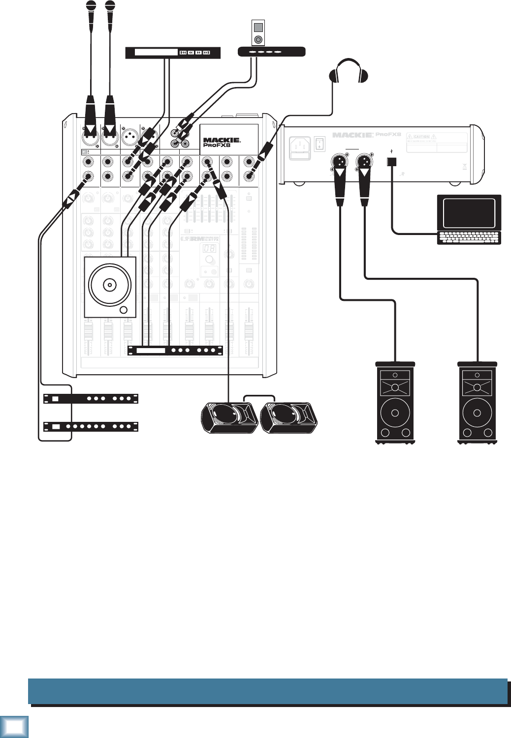
This diagram shows a guitar connected directly to channel 1 (with the hi-z switch pressed in), micro-
phones attached to channels 2, 3, and 4, guitar effects processors connected to the left line-level input of
channel 5/6, and 7/8, a keyboard attached to channel 9/10's line-level inputs, and a drum machine
connected to channel 11/12. An iPod docking station is attached to the stereo tape inputs. An effects
processor receives a mono input from the FX send, and its stereo outputs connect to the stereo return
inputs.
Mackie SRM450v2 powered speakers are connected to the left and right main output. Two of these
speakers are also set up as stage monitors, and connect to the mixer's monitor output via a graphic EQ.
The aux mon controls of each channel allow you to create a stage monitor mix that is independent of the
main mix. Use the external graphic EQ to adjust the stage monitor EQ as desired. Headphones are used
for monitoring, and a footswitch allows you to mute/unmute the internal effects as desired.
A laptop connects to the USB port, and allows the 2-channel main mix of the performance to be re-
corded using Tracktion software. Two channels of audio can also play from your computer to the main
mix.
7
Owner’s Manual
Owner’s Manual
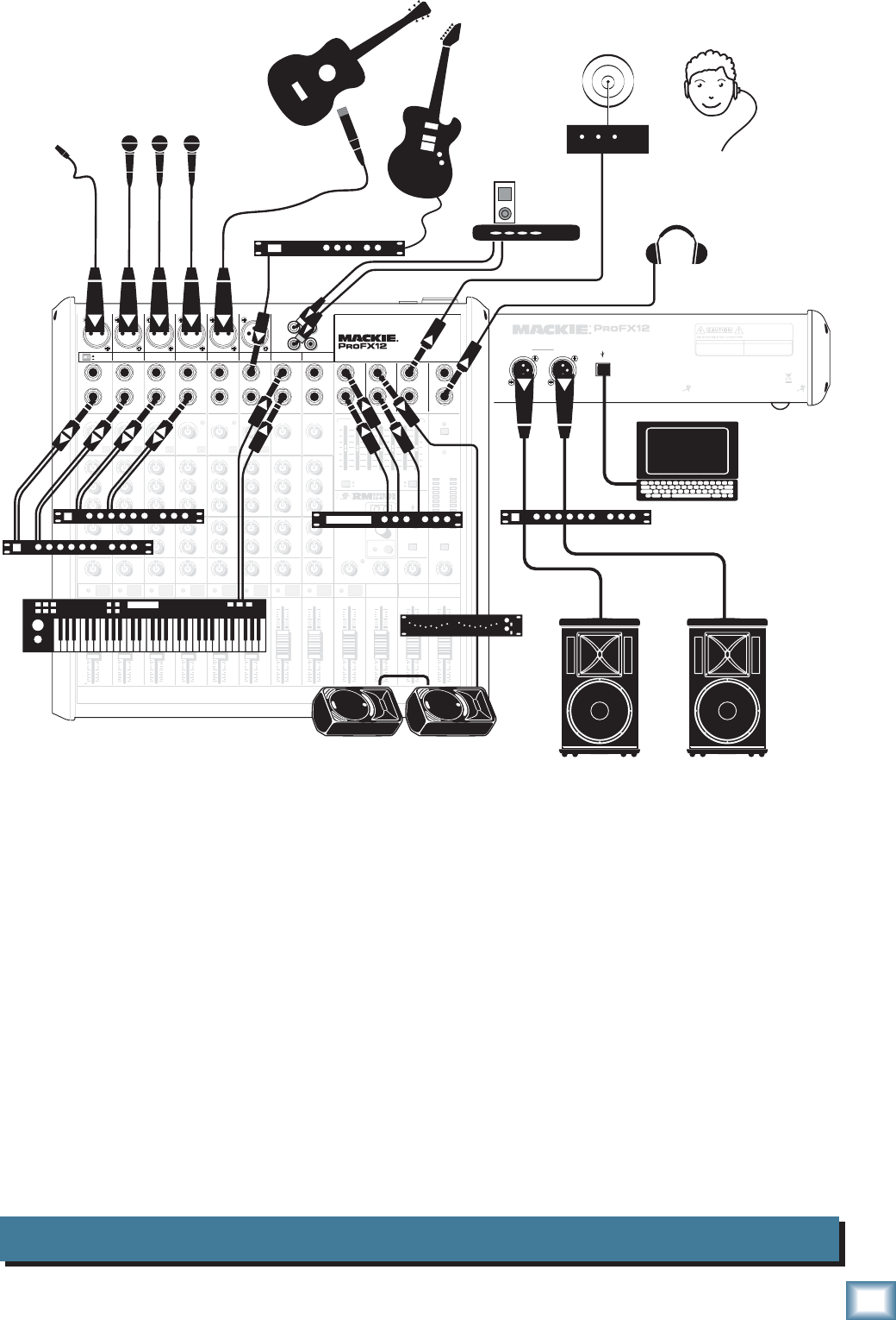
House of Worship System ProFX12
MAIN
RIGHT
(BALANCED)
MAIN
LEFT
USB
(BALANCED)
DESIGNED BY MACKOIDS IN WOODINVILLE, WA, USA • MANUFACTURED IN CHINA
FABRIQUE EN CHINE • COPYRIGHT ©2008 • "MACKIE" AND THE RUNNING MAN FIGURE
ARE TRADEMARKS OF LOUD TECHNOLOGIES, INC. • PATENT PENDING.
POWER
ON PROFESSIONAL MIC/LINE MIXER WITH FX
FUSE: T1.6AL AC250V
~100- 240V 50/60 Hz 25W
THIS DEVICE COMPLIES WITH PART 15 OF THE FCC RULES AND THE ICES-003 FOR
CANADA. OPERATION IS SUBJECT TO THE FOLLOWING TWO CONDITIONS: (1) THIS
DEVICE MAY NOT CAUSE HARMFUL INTERFERENCE, AND (2) THIS DEVICE MUST
ACCEPT ANY INTERFERENCE RECEIVED, INCLUDING INTERFERENCE THAT MAY
CAUSE UNDESIRED OPERATION.
MANUFACTURING DATE
SERIAL NUMBER
WARNING:
TO REDUCE THE RISK OF FIRE OR ELECTRIC
SHOCK, DO NOT EXPOSE THIS EQUIPMENT TO RAIN OR
MOISTURE. DO NOT REMOVE COVER. NO USER SERVICEABLE
PARTS INSIDE. REFER SERVICING TO QUALIFIED PERSONNEL.
AVIS:
RISQUE DE CHOC ELECTRIQUE — NE PAS OUVRIR
8K4K2K1K500250125
15
15
10
10
5
5
0
15
15
10
10
5
5
0
TAP E
IN
ST RETURN MAIN OUT PHONES
FOOTSWITCH
PHONES
TAP E
OUT
L
R
L
(UNBALANCED)
R
STEREO GRAPHIC EQ
FX SEND
MID
2.5kHz
MID
2.5kHz
MID
2.5kHz
MID
2.5kHz
MID
2.5kHz
80Hz
LOW
U
+15-15
U
+15-15
U
+15-15
LINE IN 4
INSERT
RL
LOW CUT
100 Hz
U
GAIN
M
I
C
G
A
I
N
U+50
-20dB +30dB
4
12kHz
HI
MID
2.5kHz
80Hz
LOW
U
+15-15
U
+15-15
U
+15-15
12kHz
HI
MID
2.5kHz
80Hz
LOW
U
+15-15
U
+15-15
U
+15-15
12kHz
HI
MID
2.5kHz
80Hz
LOW
U
+15-15
U
+15-15
U
+15-15
12kHz
HI
PAN
AUX
U
+15
OO
MON
FX
U
+15
OO
RL
PAN
AUX
U
+15
OO
MON
FX
U
+15
OO
RL
PAN
AUX
U
+15
OO
MON
FX
U
+15
OO
RL
PAN
AUX
U
+15
OO
MON
FX
U
+15
OO
80Hz
LOW
U
+15-15
U
+15-15
U
+15-15
RL
LOW CUT
100 Hz
12kHz
HI
PAN
AUX
U
+15
OO
MON
FX
U
+15
OO
80Hz
LOW
U
+15-15
U
+15-15
U
+15-15
BAL /
UNBAL
(MONO) (MONO) (MONO) (MONO)
LINE IN 7
LINE IN 8
BAL /
UNBAL LINE IN 9
RL
LOW CUT
100 Hz
GAIN
7/85/6
12kHz
HI
PAN
AUX
U
+15
OO
MON
FX
U
+15
OO
80Hz
LOW
U
+15-15
U
+15-15
U
+15-15
RL
M
I
C
G
A
I
N
U+50
GAIN
M
I
C
G
A
I
N
U+50
9/10
12kHz
HI
LEVEL
SET
LEVEL
SET
LEVEL
SET
LOW CUT
100 Hz
U
GAIN
M
I
C
G
A
I
N
U+50
-20dB +30dB
LEVEL
SET
LEVEL
SET
LEVEL
SET
LOW CUT
100 Hz
U
GAIN
M
I
C
G
A
I
N
U+50
-20dB +30dB
LOW CUT
100 Hz
U
GAIN
M
I
C
G
A
I
N
U+50
-20dB +30dB
PAN
AUX
U
+15
OO
MON
FX
U
+15
OO
GAIN
MIC MIC MIC MIC MIC MIC
80Hz
LOW
U
+15-15
U
+15-15
U
+15-15
U
+20-20
GAIN
U
+20-20
RL
11/12 ST RTN FX RTN
EQEQEQEQ EQ EQ EQ EQ
12kHz
HI
PAN
AUX
U
+15
OO
MON
FX
U
+15
OO
U
+15
FX TO MON
FX MASTER
U
+15
OO
OO
dB
30
20
10
10
OO
40
50
5
5
U
60
dB
30
20
10
10
OO
40
50
5
5
U
60
dB
30
20
10
10
OO
40
50
5
5
U
60
dB
30
20
10
10
OO
40
50
5
5
U
60
dB
30
20
10
10
OO
40
50
5
5
U
60
dB
30
20
10
10
OO
40
50
5
5
U
60
dB
30
20
10
10
OO
40
50
5
5
U
60
dB
30
20
10
10
OO
40
50
5
5
U
60
dB
30
20
10
10
OO
40
50
5
5
U
60
dB
30
20
10
10
OO
40
50
5
5
U
60
dB
30
20
10
10
OO
40
50
5
5
U
60
dB
30
20
10
10
OO
40
50
5
5
U
60
L
R
(MONO)
LINE IN 5
LINE IN 6
BAL /
UNBAL
L
R
LINE IN 10
BAL /
UNBAL
L
R
LINE IN 11
LINE IN 12
BAL /
UNBAL
L
R
BAL /
UNBAL
L
R
BAL /
UNBAL
L
R
MON SEND
BAL /
UNBAL
BAL /
UNBAL
PRESETS
FX PRESETS
01 BRIGHT ROOM
02 WARM LOUNGE
03 SMALL STAGE
04 WARM THEATER
05 WARM HALL
06 CONCERT HALL
13 DELAY 1 (300ms)
14 DELAY 2 (380ms)
15 DELAY 3 (480ms)
16 REVERB + DLY (250ms)
07 PLATE REVERB
08 CATHEDRAL
09 CHORUS
10 CHORUS + REV
11 DOUBLER
12 TAPE SLAP
MON MAIN
4
LINE IN 3
INSERT
3
BAL /
UNBAL
3
LINE IN 2
INSERT
2
BAL /
UNBAL
BAL /
UNBAL
2
LINE/HI-Z IN 1
INSERT
1 5/6 7/8 9/10 11/12
0dB=0dBu
MAIN
METERS
OL
4
6
3
10
15
7
10
20
30
0
2
BREAK
(MUTES ALL CHANNELS)
PHANTOM
POWER
POWER
OO
+20
U
TAPE LEVEL
OO
+20
U
USB THRU
LINE
HI-Z
OO
MAX
1
OL OL OL OL OL OL OL OL OL
OL
MAIN MIX
MON
EQ IN
BYPASS
PROFESSIONAL MIC/LINE MIXER WITH FX
RL
INPUT LEVEL
USB
MUTE
MUTE MUTE MUTE MUTE MUTE MUTE MUTE MUTE MUTE
48V
Mono Effects
Microphones
Lavalier
Clip-on Mic
Headphones
SRM450v2 Powered Monitors
Laptop
with Tracktion
recording
the service
SR1521z Powered S
p
eakers
Effects Processor
Mono in, Stereo out
Dual Compressors
Compressor/Limiter
Acoustic Guitar
and Mic
iPod
Docking Station
Monitor EQ
Assistive Listening
System
Keyboard
Electric
Guitar
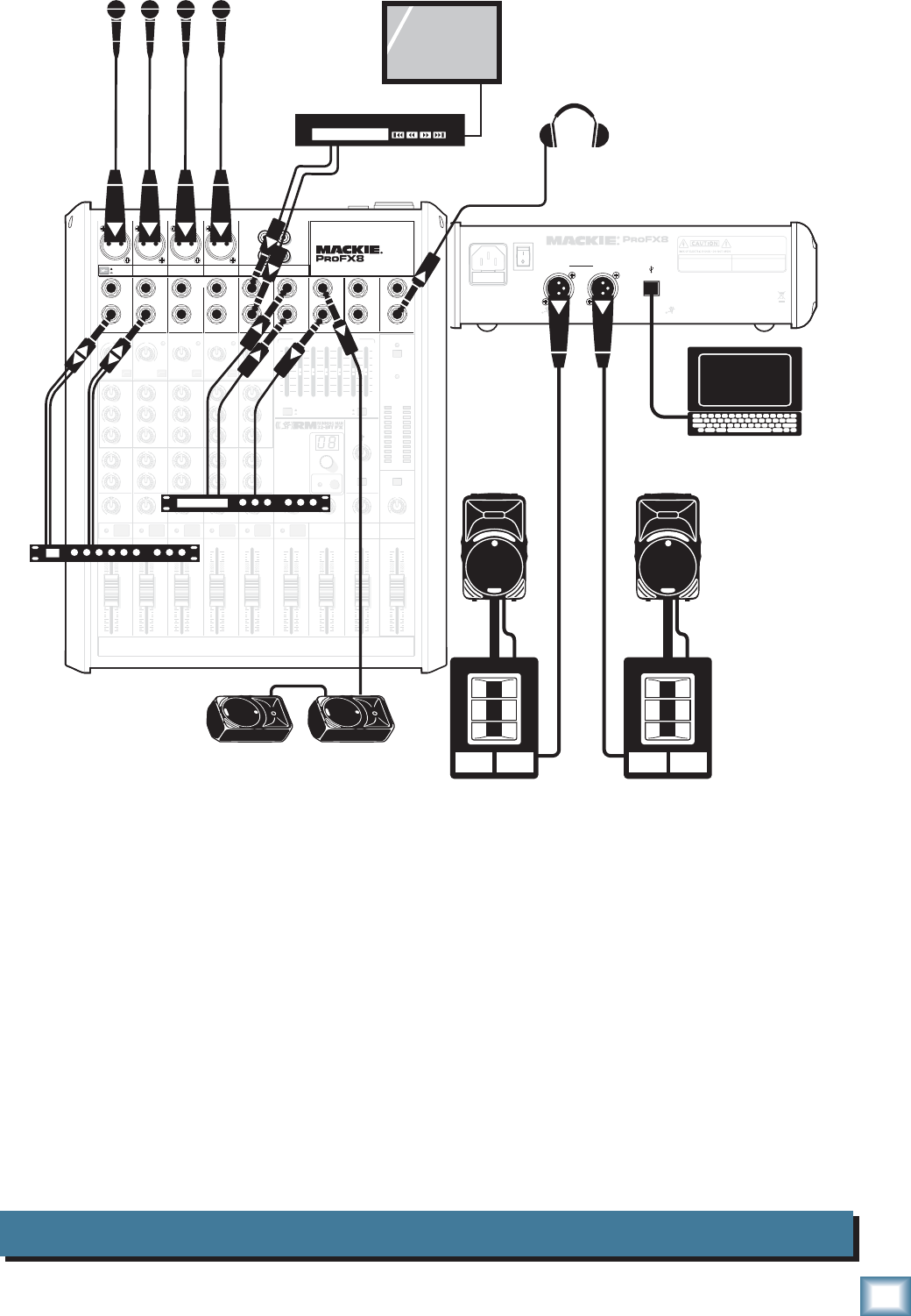
This diagram shows various microphones attached to channels 1 to 4, a guitar mic on channel 5/6, a
guitar effects processor connected to the left line-level input of channel 7/8, and a keyboard attached to
channel 9/10's line-level inputs. An iPod docking station is attached to the stereo tape inputs. An effects
processor receives a mono input from the FX send, and its stereo outputs connect to the stereo return
inputs. An assistive listening system is connected to the line-level main output. Dual compressors are con-
nected to the inserts of channels 1 to 4, allowing vocal compression.
Mackie SR1521z powered speakers are connected to the left and right main output, via a compressor/
limiter. Two SRM450v2 powered speakers are set up as stage monitors, and connect to the mixer's moni-
tor output via a graphic EQ. The aux mon controls of each channel allow you to create a stage monitor
mix that is independent of the main mix. Use the external graphic EQ to adjust the stage monitor EQ as
desired. Headphones are used for monitoring.
A laptop connects to the USB port, and allows the 2-channel main mix of the service to be recorded us-
ing Tracktion software. Two channels of audio can also play from your computer to the main mix.
8
ProFX8 and ProFX12
ProFX8 and ProFX12
DJ System ProFX8
MAIN
RIGHT
(BALANCED)
MAIN
LEFT
USB
(BALANCED)
POWER
ON
DESIGNED BY MACKOIDS IN WOODINVILLE, WA, USA • MANUFACTURED IN CHINA
FABRIQUE EN CHINE • COPYRIGHT ©2008 • "MACKIE" AND THE RUNNING MAN FIGURE
ARE TRADEMARKS OF LOUD TECHNOLOGIES, INC. • PATENT PENDING.
THIS DEVICE COMPLIES WITH PART 15 OF THE FCC RULES AND THE ICES-003 FOR
CANADA. OPERATION IS SUBJECT TO THE FOLLOWING TWO CONDITIONS: (1) THIS
DEVICE MAY NOT CAUSE HARMFUL INTERFERENCE, AND (2) THIS DEVICE MUST
ACCEPT ANY INTERFERENCE RECEIVED, INCLUDING INTERFERENCE THAT MAY
CAUSE UNDESIRED OPERATION.
MANUFACTURING DATE
SERIAL NUMBER
WARNING :
TO REDUCE THE RISK OF FIRE OR ELECTRIC
SHOCK, DO NOT EXPOSE THIS EQUIPMENT TO RAIN OR
MOISTURE. DO NOT REMOVE COVER. NO USER SERVICEABLE
PARTS INSIDE. REFER SERVICING TO QUALIFIED PERSONNEL.
AVIS:
RISQUE DE CHOC ELECTRIQUE — NE PAS OUVRIR
FUSE: T1.6AL AC250V
~100- 240V 50/60 Hz 20W
PROFESSIONAL MIC/LINE MIXER WITH FX
13 DELAY 1 (300ms)
14 DELAY 2 (380ms)
15 DELAY 3 (480ms)
16 REVERB + DLY (250ms)
8K4K2K1K
500250125
15
15
10
10
5
5
0
15
15
10
10
5
5
0
TAPE
IN
ST RETURN MAIN OUT PHONES
FOOTSWITCH
PHONES
TAPE
OUT
L
R
L
(UNBALANCED)
R
0dB=0dBu
MAIN
METERS
RL
OL
4
6
3
10
15
7
10
20
30
0
2
BREAK
(MUTES ALL CHANNELS)
PHANTOM
POWER
POWER
STEREO GRAPHIC EQ
FX SEND
MID
2.5kHz
MID
2.5kHz
MID
2.5kHz
MID
2.5kHz
MID
2.5kHz
80Hz
LOW
U
+15-15
U
+15-15
U
+15-15
INSERT
RL
LOW CUT
100 Hz
U
GAIN
M
I
C
G
A
I
N
U+50
-20dB +30dB
OL
1
EQ
12kHz
HI
PAN
AUX
U
+15
OO
MON
FX
U
+15
OO
80Hz
LOW
U
+15-15
U
+15-15
U
+15-15
RL
LOW CUT
100 Hz
U
GAIN
M
I
C
G
A
I
N
U+50
-20dB +30dB
2
EQ
12kHz
HI
PAN
AUX
U
+15
OO
MON
FX
U
+15
OO
80Hz
LOW
U
+15-15
U
+15-15
U
+15-15
LINE IN 2 LINE/HI-Z IN 1
INSERT
BAL /
UNBAL
(MONO) (MONO) (MONO) (MONO)
LINE IN 3
LINE IN 4
BAL /
UNBAL LINE IN 5
RL
LOW CUT
100 Hz
GAIN
3/4
EQ
12kHz
HI
PAN
AUX
U
+15
OO
MON
FX
U
+15
OO
80Hz
LOW
U
+15-15
U
+15-15
U
+15-15
RL
LOW CUT
100Hz
GAIN
M
I
C
G
A
I
N
U+50
M
I
C
G
A
I
N
U+50
5/6
EQ
12kHz
HI
LEVEL
SET
LEVEL
SET
LEVEL
SET
LEVEL
SET
PAN
AUX
U
+15
OO
MON
FX
U
+15
OO
GAIN
MIC MIC MIC MIC
80Hz
LOW
U
+15-15
U
+15-15
U
+15-15
U
+20-20
RL
7/8 ST RTN FX RTN
EQ
12kHz
HI
PAN
AUX
U
+15
OO
MON
FX
U
+15
OO
U
+15
FX TO MON
FX MASTER
U
+15
OO
OO
dB
30
20
10
10
OO
40
50
5
5
U
60
dB
30
20
10
10
OO
40
50
5
5
U
60
dB
30
20
10
10
OO
40
50
5
5
U
60
dB
30
20
10
10
OO
40
50
5
5
U
60
dB
30
20
10
10
OO
40
50
5
5
U
60
dB
30
20
10
10
OO
40
50
5
5
U
60
30
20
10
OO
40
50
5
5
U
60
dB
30
20
10
10
OO
40
50
5
5
U
60
dB
30
20
10
10
OO
40
50
5
5
U
60
L
R
LINE IN 6
BAL /
UNBAL
L
R
LINE IN 7
LINE IN 8
BAL /
UNBAL
L
R
BAL /
UNBAL
L
R
BAL /
UNBAL
L
R
MON SEND
BAL /
UNBAL
BAL /
UNBAL
MUTE
PRESETS
FX PRESETS
OL OL OL OL OL
INPUT LEVEL
USB
OO
+20
U
TAPE LEVEL
OO
+20
U
MON MAIN
1 2 3/4 5/6 7/8
OL
USB THRU
LINE
HI-Z
MAIN MIX
MON
EQ IN
BYPASS
01 BRIGHT ROOM
02 WARM LOUNGE
03 SMALL STAGE
04 WARM THEATER
05 WARM HALL
06 CONCERT HALL
07 PLATE REVERB
08 CATHEDRAL
09 CHORUS
10 CHORUS + REV
11 DOUBLER
12 TAPE SLAP
OO
MAX
PROFESSIONAL MIC/LINE MIXER WITH FX
LINE
HI-Z
MUTE MUTE MUTE MUTE MUTE MUTE
48V
Headphones
Effects Processor
Reverb
Compressor
CD Player
Laptop running Tracktion
and DJ software
SR1530z Powered S
p
eakers
SRM450v2 Powered Monitors
Microphones
iPod
Docking Station
CD Turntable
This diagram shows two microphones attached to channels 1 and 2, a CD player connected to the line-
level inputs of channel 3/4, a CD turntable connected to the line-level inputs of channel 7/8. An iPod
docking station is attached to the stereo tape inputs. An effects processor receives a mono input from the
FX send, and its stereo outputs connect to the stereo return inputs. A reverb and compressor are con-
nected to the insert of channel 1 allowing vocal compression and a touch of reverb.
Mackie SR1530z powered speakers are connected to the left and right main output. Two SRM450v2
powered speakers are set up as stage monitors, and connect to the mixer's monitor output. The aux mon
controls of each channel allow you to create a stage monitor mix that is independent of the main mix.
Switch the internal graphic EQ to adjust the stage monitor EQ if desired. Headphones are used for moni-
toring.
A laptop connects to the USB port, and allows 2-channel output of DJ software to play in your main
mix. It also can be used to record your set on the computer for posterity.
9
Owner’s Manual
Owner’s Manual
Karaoke System ProFX8
MAIN
RIGHT
(BALANCED)
MAIN
LEFT
USB
(BALANCED)
POWER
ON
DESIGNED BY MACKOIDS IN WOODINVILLE, WA, USA • MANUFACTURED IN CHINA
FABRIQUE EN CHINE • COPYRIGHT ©2008 • "MACKIE" AND THE RUNNING MAN FIGURE
ARE TRADEMARKS OF LOUD TECHNOLOGIES, INC. • PATENT PENDING.
THIS DEVICE COMPLIES WITH PART 15 OF THE FCC RULES AND THE ICES-003 FOR
CANADA. OPERATION IS SUBJECT TO THE FOLLOWING TWO CONDITIONS: (1) THIS
DEVICE MAY NOT CAUSE HARMFUL INTERFERENCE, AND (2) THIS DEVICE MUST
ACCEPT ANY INTERFERENCE RECEIVED, INCLUDING INTERFERENCE THAT MAY
CAUSE UNDESIRED OPERATION.
MANUFACTURING DATE
SERIAL NUMBER
WARNING :
TO REDUCE THE RISK OF FIRE OR ELECTRIC
SHOCK, DO NOT EXPOSE THIS EQUIPMENT TO RAIN OR
MOISTURE. DO NOT REMOVE COVER. NO USER SERVICEABLE
PARTS INSIDE. REFER SERVICING TO QUALIFIED PERSONNEL.
AVIS :
RISQUE DE CHOC ELECTRIQUE — NE PAS OUVRIR
FUSE: T1.6AL AC250V
~100- 240V 50/60 Hz 20W
PROFESSIONAL MIC/LINE MIXER WITH FX
13 DELAY 1 (300ms)
14 DELAY 2 (380ms)
15 DELAY 3 (480ms)
16 REVERB + DLY (250ms)
8K4K2K1K
500250125
15
15
10
10
5
5
0
15
15
10
10
5
5
0
TAPE
IN
ST RETURN MAIN OUT PHONES
FOOTSWITCH
PHONES
TAPE
OUT
L
R
L
(UNBALANCED)
R
0dB=0dBu
MAIN
METERS
RL
OL
4
6
3
10
15
7
10
20
30
0
2
BREAK
(MUTES ALL CHANNELS)
PHANTOM
POWER
POWER
STEREO GRAPHIC EQ
FX SEND
MID
2.5kHz
MID
2.5kHz
MID
2.5kHz
MID
2.5kHz
MID
2.5kHz
80Hz
LOW
U
+15-15
U
+15-15
U
+15-15
INSERT
RL
LOW CUT
100 Hz
U
GAIN
M
I
C
G
A
I
N
U+50
-20dB +30dB
OL
1
EQ
12kHz
HI
PAN
AUX
U
+15
OO
MON
FX
U
+15
OO
80Hz
LOW
U
+15-15
U
+15-15
U
+15-15
RL
LOW CUT
100 Hz
U
GAIN
M
I
C
G
A
I
N
U+50
-20dB +30dB
2
EQ
12kHz
HI
PAN
AUX
U
+15
OO
MON
FX
U
+15
OO
80Hz
LOW
U
+15-15
U
+15-15
U
+15-15
LINE IN 2 LINE/HI-Z IN 1
INSERT
BAL /
UNBAL
(MONO) (MONO) (MONO) (MONO)
LINE IN 3
LINE IN 4
BAL /
UNBAL LINE IN 5
RL
LOW CUT
100 Hz
GAIN
3/4
EQ
12kHz
HI
PAN
AUX
U
+15
OO
MON
FX
U
+15
OO
80Hz
LOW
U
+15-15
U
+15-15
U
+15-15
RL
LOW CUT
100Hz
GAIN
M
I
C
G
A
I
N
U+50
M
I
C
G
A
I
N
U+50
5/6
EQ
12kHz
HI
LEVEL
SET
LEVEL
SET
LEVEL
SET
LEVEL
SET
PAN
AUX
U
+15
OO
MON
FX
U
+15
OO
GAIN
MIC MIC MIC MIC
80Hz
LOW
U
+15-15
U
+15-15
U
+15-15
U
+20-20
RL
7/8 ST RTN FX RTN
EQ
12kHz
HI
PAN
AUX
U
+15
OO
MON
FX
U
+15
OO
U
+15
FX TO MON
FX MASTER
U
+15
OO
OO
dB
30
20
10
10
OO
40
50
5
5
U
60
dB
30
20
10
10
OO
40
50
5
5
U
60
dB
30
20
10
10
OO
40
50
5
5
U
60
dB
30
20
10
10
OO
40
50
5
5
U
60
dB
30
20
10
10
OO
40
50
5
5
U
60
dB
30
20
10
10
OO
40
50
5
5
U
60
dB
30
20
10
10
OO
40
50
5
5
U
60
dB
30
20
10
10
OO
40
50
5
5
U
60
dB
30
20
10
10
OO
40
50
5
5
U
60
L
R
LINE IN 6
BAL /
UNBAL
L
R
LINE IN 7
LINE IN 8
BAL /
UNBAL
L
R
BAL /
UNBAL
L
R
BAL /
UNBAL
L
R
MON SEND
BAL /
UNBAL
BAL /
UNBAL
MUTE
PRESETS
FX PRESETS
OL OL OL OL OL
INPUT LEVEL
USB
OO
+20
U
TAPE LEVEL
OO
+20
U
MON MAIN
1 2 3/4 5/6 7/8
OL
USB THRU
LINE
HI-Z
MAIN MIX
MON
EQ IN
BYPASS
01 BRIGHT ROOM
02 WARM LOUNGE
03 SMALL STAGE
04 WARM THEATER
05 WARM HALL
06 CONCERT HALL
07 PLATE REVERB
08 CATHEDRAL
09 CHORUS
10 CHORUS + REV
11 DOUBLER
12 TAPE SLAP
OO
MAX
PROFESSIONAL MIC/LINE MIXER WITH FX
LINE
HI-Z
MUTE MUTE MUTE MUTE MUTE MUTE
48V
SRM350v2 Powered Monitors
Microphones
Headphones
Effects Processor
CD+G Player
TV monitor
Video
Laptop Computer
with Karaoke Softwar
e
SWA1501
Powered
Subwoofer
SRM450v2
Powered
Speaker
Dual Compressor
This diagram shows microphones attached to channels 1 to 4, and a CD+G player connected to the
line-level inputs of channel 7/8. An effects processor receives a mono input from the FX send, and its
stereo outputs connect to the stereo return inputs. A dual compressor is connected to the insert of channel
1, and 2, allowing vocal compression.
Mackie SRM450v2 powered speakers and SWA1501 powered subwoofers are connected to the left
and right main output. Two SRM450v2 powered speakers are set up as stage monitors, and connect to
the mixer's monitor output. The aux mon controls of each channel allow you to create a stage monitor
mix that is independent of the main mix. Headphones are used for monitoring.
A laptop running Karaoke software connects to the USB port, and allows a 2-channel output to play in
the main mix.
The CD+G player allows karaoke text and graphics to be displayed on your TV monitor.
10
ProFX8 and ProFX12
ProFX8 and ProFX12
Home Studio System ProFX8
MAIN
RIGHT
(BALANCED)
MAIN
LEFT
USB
(BALANCED)
POWER
ON
DESIGNED BY MACKOIDS IN WOODINVILLE, WA, USA • MANUFACTURED IN CHINA
FABRIQUE EN CHINE • COPYRIGHT ©2008 • "MACKIE" AND THE RUNNING MAN FIGURE
ARE TRADEMARKS OF LOUD TECHNOLOGIES, INC. • PATENT PENDING.
THIS DEVICE COMPLIES WITH PART 15 OF THE FCC RULES AND THE ICES-003 FOR
CANADA. OPERATION IS SUBJECT TO THE FOLLOWING TWO CONDITIONS: (1) THIS
DEVICE MAY NOT CAUSE HARMFUL INTERFERENCE, AND (2) THIS DEVICE MUST
ACCEPT ANY INTERFERENCE RECEIVED, INCLUDING INTERFERENCE THAT MAY
CAUSE UNDESIRED OPERATION.
MANUFACTURING DATE
SERIAL NUMBER
WARNING:
TO REDUCE THE RISK OF FIRE OR ELECTRIC
SHOCK, DO NOT EXPOSE THIS EQUIPMENT TO RAIN OR
MOISTURE. DO NOT REMOVE COVER. NO USER SERVICEABLE
PARTS INSIDE. REFER SERVICING TO QUALIFIED PERSONNEL.
AVIS :
RISQUE DE CHOC ELECTRIQUE — NE PAS OUVRIR
FUSE: T1.6AL AC250V
~100- 240V 50/60 Hz 20W
PROFESSIONAL MIC/LINE MIXER WITH FX
13 DELAY 1 (300ms)
14 DELAY 2 (380ms)
15 DELAY 3 (480ms)
16 REVERB + DLY (250ms)
8K4K2K1K
500250125
15
15
10
10
5
5
0
15
15
10
10
5
5
0
TAPE
IN
ST RETURN MAIN OUT PHONES
FOOTSWITCH
PHONES
TAPE
OUT
L
R
L
(UNBALANCED)
R
0dB=0dBu
MAIN
METERS
RL
OL
4
6
3
10
15
7
10
20
30
0
2
BREAK
(MUTES ALL CHANNELS)
PHANTOM
POWER
POWER
STEREO GRAPHIC EQ
FX SEND
MID
2.5kHz
MID
2.5kHz
MID
2.5kHz
MID
2.5kHz
MID
2.5kHz
80Hz
LOW
U
+15-15
U
+15-15
U
+15-15
INSERT
RL
LOW CUT
100 Hz
U
GAIN
M
I
C
G
A
I
N
U+50
-20dB +30dB
OL
1
EQ
12kHz
HI
PAN
AUX
U
+15
OO
MON
FX
U
+15
OO
80Hz
LOW
U
+15-15
U
+15-15
U
+15-15
RL
LOW CUT
100 Hz
U
GAIN
M
I
C
G
A
I
N
U+50
-20dB +30dB
2
EQ
12kHz
HI
PAN
AUX
U
+15
OO
MON
FX
U
+15
OO
80Hz
LOW
U
+15-15
U
+15-15
U
+15-15
LINE IN 2 LINE/HI-Z IN 1
INSERT
BAL /
UNBAL
(MONO) (MONO) (MONO) (MONO)
LINE IN 3
LINE IN 4
BAL /
UNBAL LINE IN 5
RL
LOW CUT
100 Hz
GAIN
3/4
EQ
12kHz
HI
PAN
AUX
U
+15
OO
MON
FX
U
+15
OO
80Hz
LOW
U
+15-15
U
+15-15
U
+15-15
RL
LOW CUT
100Hz
GAIN
M
I
C
G
A
I
N
U+50
M
I
C
G
A
I
N
U+50
5/6
EQ
12kHz
HI
LEVEL
SET
LEVEL
SET
LEVEL
SET
LEVEL
SET
PAN
AUX
U
+15
OO
MON
FX
U
+15
OO
GAIN
MIC MIC MIC MIC
80Hz
LOW
U
+15-15
U
+15-15
U
+15-15
U
+20-20
RL
7/8 ST RTN FX RTN
EQ
12kHz
HI
PAN
AUX
U
+15
OO
MON
FX
U
+15
OO
U
+15
FX TO MON
FX MASTER
U
+15
OO
OO
dB
30
20
10
10
OO
40
50
5
5
U
60
dB
30
20
10
10
OO
40
50
5
5
U
60
dB
30
20
10
10
OO
40
50
5
5
U
60
dB
30
20
10
10
OO
40
50
5
5
U
60
dB
30
20
10
10
OO
40
50
5
5
U
60
dB
30
20
10
10
OO
40
50
5
5
U
60
dB
30
20
10
10
OO
40
50
5
5
U
60
dB
30
20
10
10
OO
40
50
5
5
U
60
dB
30
20
10
10
OO
40
50
5
5
U
60
L
R
LINE IN 6
BAL /
UNBAL
L
R
LINE IN 7
LINE IN 8
BAL /
UNBAL
L
R
BAL /
UNBAL
L
R
BAL /
UNBAL
L
R
MON SEND
BAL /
UNBAL
BAL /
UNBAL
MUTE
PRESETS
FX PRESETS
OL OL OL OL OL
INPUT LEVEL
USB
OO
+20
U
TAPE LEVEL
OO
+20
U
MON MAIN
1 2 3/4 5/6 7/8
OL
USB THRU
LINE
HI-Z
MAIN MIX
MON
EQ IN
BYPASS
01 BRIGHT ROOM
02 WARM LOUNGE
03 SMALL STAGE
04 WARM THEATER
05 WARM HALL
06 CONCERT HALL
07 PLATE REVERB
08 CATHEDRAL
09 CHORUS
10 CHORUS + REV
11 DOUBLER
12 TAPE SLAP
OO
MAX
PROFESSIONAL MIC/LINE MIXER WITH FX
LINE
HI-Z
MUTE MUTE MUTE MUTE MUTE MUTE
48V
Desktop
Mac or PC
using Tracktion
Condenser
microphone
for vocals Amplifier
Modeler
Electric
Guitar
Headphones
Headphone Amp
Electronic Drum Kit
Keyboard
MR8 Powered Reference Monitors
press HI-Z
button
Acoustic
Guitar with
pickup
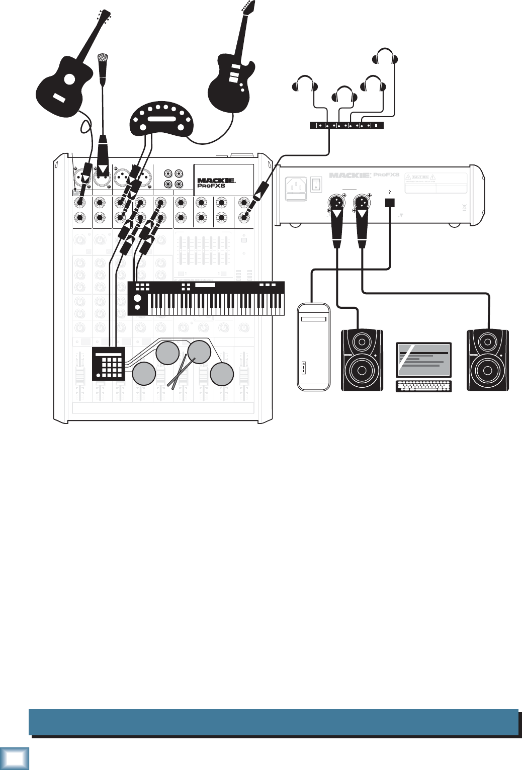
This diagram shows an acoustic guitar connected directly to channel 1 (with hi-z switch pressed in), a
condenser microphone attached to channel 2 mic input, a guitar amplifi er modeler connected to the line-
level inputs of channel 3/4, an electronic drum kit connected to channel 5/6, and a keyboard attached
to channel 7/8.
Mackie MR8 powered reference monitors are connected to the left and right main output, for careful
and accurate monitoring of your performances.
A desktop computer connects to the USB port, and allows the 2-channel main mix to be recorded and
2 channels to be played back using Tracktion software.
11
Owner’s Manual
Owner’s Manual
Podcast System ProFX8
MAIN
RIGHT
(BALANCED)
MAIN
LEFT
USB
(BALANCED)
POWER
ON
DESIGNED BY MACKOIDS IN WOODINVILLE, WA, USA • MANUFACTURED IN CHINA
FABRIQUE EN CHINE • COPYRIGHT ©2008 • "MACKIE" AND THE RUNNING MAN FIGURE
ARE TRADEMARKS OF LOUD TECHNOLOGIES, INC. • PATENT PENDING.
THIS DEVICE COMPLIES WITH PART 15 OF THE FCC RULES AND THE ICES-003 FOR
CANADA. OPERATION IS SUBJECT TO THE FOLLOWING TWO CONDITIONS: (1) THIS
DEVICE MAY NOT CAUSE HARMFUL INTERFERENCE, AND (2) THIS DEVICE MUST
ACCEPT ANY INTERFERENCE RECEIVED, INCLUDING INTERFERENCE THAT MAY
CAUSE UNDESIRED OPERATION.
MANUFACTURING DATE
SERIAL NUMBER
WARNING:
TO REDUCE THE RISK OF FIRE OR ELECTRIC
SHOCK, DO NOT EXPOSE THIS EQUIPMENT TO RAIN OR
MOISTURE. DO NOT REMOVE COVER. NO USER SERVICEABLE
PARTS INSIDE. REFER SERVICING TO QUALIFIED PERSONNEL.
AVIS:
RISQUE DE CHOC ELECTRIQUE — NE PAS OUVRIR
FUSE: T1.6AL AC250V
~100- 240V 50/60 Hz 20W
PROFESSIONAL MIC/LINE MIXER WITH FX
13 DELAY 1 (300ms)
14 DELAY 2 (380ms)
15 DELAY 3 (480ms)
16 REVERB + DLY (250ms)
8K4K2K1K
500250125
15
15
10
10
5
5
0
15
15
10
10
5
5
0
TAPE
IN
ST RETURN MAIN OUT PHONES
FOOTSWITCH
PHONES
TAPE
OUT
L
R
L
(UNBALANCED)
R
0dB=0dBu
MAIN
METERS
RL
OL
4
6
3
10
15
7
10
20
30
0
2
BREAK
(MUTES ALL CHANNELS)
PHANTOM
POWER
POWER
STEREO GRAPHIC EQ
FX SEND
MID
2.5kHz
MID
2.5kHz
MID
2.5kHz
MID
2.5kHz
MID
2.5kHz
80Hz
LOW
U
+15-15
U
+15-15
U
+15-15
INSERT
RL
LOW CUT
100 Hz
U
GAIN
M
I
C
G
A
I
N
U+50
-20dB +30dB
OL
1
EQ
12kHz
HI
PAN
AUX
U
+15
OO
MON
FX
U
+15
OO
80Hz
LOW
U
+15-15
U
+15-15
U
+15-15
RL
LOW CUT
100 Hz
U
GAIN
M
I
C
G
A
I
N
U+50
-20dB +30dB
2
EQ
12kHz
HI
PAN
AUX
U
+15
OO
MON
FX
U
+15
OO
80Hz
LOW
U
+15-15
U
+15-15
U
+15-15
LINE IN 2 LINE/HI-Z IN 1
INSERT
BAL /
UNBAL
(MONO) (MONO) (MONO) (MONO)
LINE IN 3
LINE IN 4
BAL /
UNBAL LINE IN 5
RL
LOW CUT
100 Hz
GAIN
3/4
EQ
12kHz
HI
PAN
AUX
U
+15
OO
MON
FX
U
+15
OO
80Hz
LOW
U
+15-15
U
+15-15
U
+15-15
RL
LOW CUT
100Hz
GAIN
M
I
C
G
A
I
N
U+50
M
I
C
G
A
I
N
U+50
5/6
EQ
12kHz
HI
LEVEL
SET
LEVEL
SET
LEVEL
SET
LEVEL
SET
PAN
AUX
U
+15
OO
MON
FX
U
+15
OO
GAIN
MIC MIC MIC MIC
80Hz
LOW
U
+15-15
U
+15-15
U
+15-15
U
+20-20
RL
7/8 ST RTN FX RTN
EQ
12kHz
HI
PAN
AUX
U
+15
OO
MON
FX
U
+15
OO
U
+15
FX TO MON
FX MASTER
U
+15
OO
OO
dB
30
20
10
10
OO
40
50
5
5
U
60
dB
30
20
10
10
OO
40
50
5
5
U
60
dB
30
20
10
10
OO
40
50
5
5
U
60
dB
30
20
10
10
OO
40
50
5
5
U
60
dB
30
20
10
10
OO
40
50
5
5
U
60
dB
30
20
10
10
OO
40
50
5
5
U
60
dB
30
20
10
10
OO
40
50
5
5
U
60
dB
30
20
10
10
OO
40
50
5
5
U
60
dB
30
20
10
10
OO
40
50
5
5
U
60
L
R
LINE IN 6
BAL /
UNBAL
L
R
LINE IN 7
LINE IN 8
BAL /
UNBAL
L
R
BAL /
UNBAL
L
R
BAL /
UNBAL
L
R
MON SEND
BAL /
UNBAL
BAL /
UNBAL
MUTE
PRESETS
FX PRESETS
OL OL OL OL OL
INPUT LEVEL
USB
OO
+20
U
TAPE LEVEL
OO
+20
U
MON MAIN
1 2 3/4 5/6 7/8
OL
USB THRU
LINE
HI-Z
MAIN MIX
MON
EQ IN
BYPASS
01 BRIGHT ROOM
02 WARM LOUNGE
03 SMALL STAGE
04 WARM THEATER
05 WARM HALL
06 CONCERT HALL
07 PLATE REVERB
08 CATHEDRAL
09 CHORUS
10 CHORUS + REV
11 DOUBLER
12 TAPE SLAP
OO
MAX
PROFESSIONAL MIC/LINE MIXER WITH FX
LINE
HI-Z
MUTE MUTE MUTE MUTE MUTE MUTE
48V
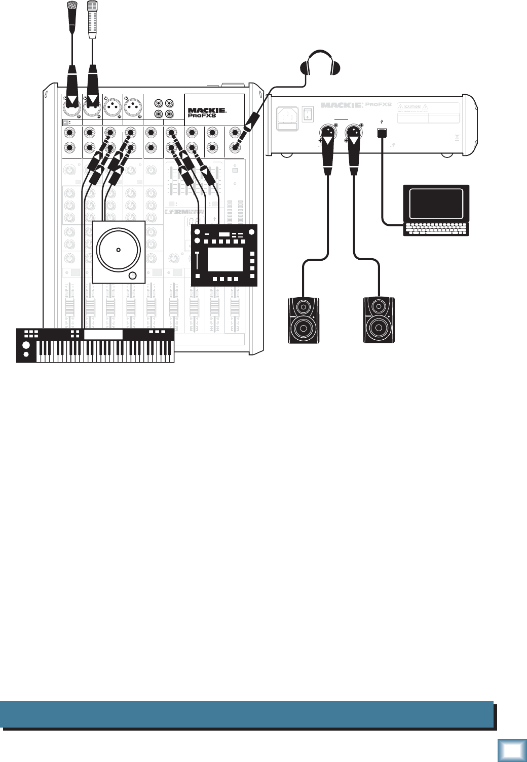
Microphones
Headphones
Laptop Computer
with Tracktion
Keyboard workstation
Effects/ Sampler
MR5 Powered Reference Monitors
CD Turntable
This diagram shows microphones attached to channel 1 and 2 mic inputs, a keyboard workstation
attached to channel 3/4's line-level inputs, and a CD turntable connected to channel 5/6's line-level
inputs. An effects/sampler receives a mono input from the FX send, and its stereo outputs connect to the
stereo return inputs.
Mackie MR5 powered reference monitors are connected to the left and right main output, for careful
and accurate monitoring of your work.
A desktop computer connects to the USB port, and allows the 2-channel main mix to be recorded and
2 channels played back using Tracktion software.
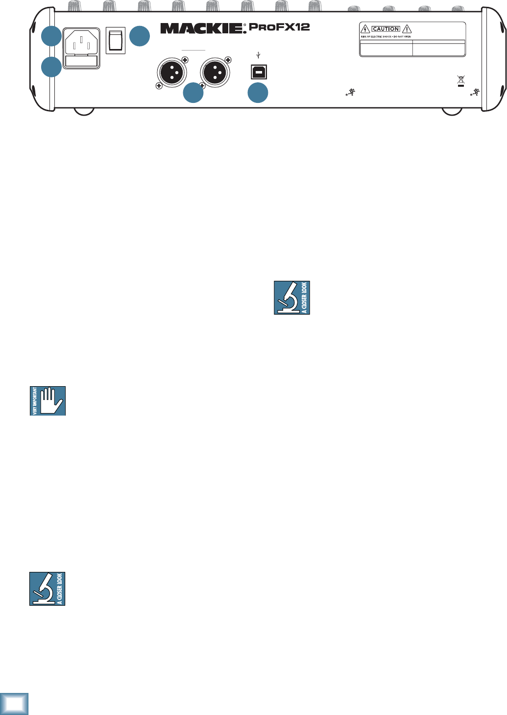
12
ProFX8 and ProFX12
ProFX8 and ProFX12
Rear Panel Features
1. POWER CONNECTION
This is a standard 3-prong IEC AC power connector.
Securely connect the supplied detachable linecord in
here, and plug the other end into an AC outlet. The
mixer has a universal power supply that can accept any
AC voltage ranging from 100 VAC to 240 VAC. No need
for voltage select switches or step-up or step-down
transformers, it will work virtually anywhere in the
world. It is less susceptible to voltage sags or spikes
than conventional power supplies, and provides greater
electromagnetic isolation and better protection against
AC line noise.
2. FUSE
The ProFX mixer is fused for your (and its own)
protection. If you suspect a blown fuse, disconnect the
power cord, pull this fuse drawer out and replace the
fuse with exactly the same type and rating.
If two fuses blow in a row, something is very
wrong, and you must stop using the mixer.
Please call our toll-free number 1-800-898-
3211 from within the U.S. (or call the distributor in your
country) and fi nd out what to do.
3. POWER SWITCH
Press the top of this rocker switch to turn on the
mixer. The front panel power LED [33] will glow with
happiness, or at least it will if you have the mixer
plugged into a suitable live AC mains supply.
Press the bottom of this switch to turn off the mixer,
whenever you feel that this would be a safe thing to do.
As a general guide, you should turn on your
mixer fi rst, before any external power ampli-
fi ers or powered speakers, and turn it off last.
This will reduce the possibility of any turn-on or turn-
off thumps in your speakers.
MAIN
RIGHT
(BALANCED)
MAIN
LEFT
USB
(BALANCED)
DESIGNED BY MACKOIDS IN WOODINVILLE, WA, USA • MANUFACTURED IN CHINA
FABRIQUE EN CHINE • COPYRIGHT ©2008 • "MACKIE" AND THE RUNNING MAN FIGURE
ARE TRADEMARKS OF LOUD TECHNOLOGIES, INC. • PATENT PENDING.
POWER
ON PROFESSIONAL MIC/LINE MIXER WITH FX
FUSE: T1.6AL AC250V
~100-240V 50/60 Hz 25W
THIS DEVICE COMPLIES WITH PART 15 OF THE FCC RULES AND THE ICES-003 FOR
CANADA. OPERATION IS SUBJECT TO THE FOLLOWING TWO CONDITIONS: (1) THIS
DEVICE MAY NOT CAUSE HARMFUL INTERFERENCE, AND (2) THIS DEVICE MUST
ACCEPT ANY INTERFERENCE RECEIVED, INCLUDING INTERFERENCE THAT MAY
CAUSE UNDESIRED OPERATION.
MANUFACTURING DATE
SERIAL NUMBER
WARNING:
TO REDUCE THE RISK OF FIRE OR ELECTRIC
SHOCK, DO NOT EXPOSE THIS EQUIPMENT TO RAIN OR
MOISTURE. DO NOT REMOVE COVER. NO USER SERVICEABLE
PARTS INSIDE. REFER SERVICING TO QUALIFIED PERSONNEL.
AVIS:
RISQUE DE CHOC ELECTRIQUE — NE PAS OUVRIR
4. XLR MAIN OUTS
These XLR connectors provide stereo line-level sig-
nals from the main mix. Connect these to the balanced
inputs of the powered speakers, or the power amplifi er
powering your main speakers.
The main mix is the sum of all active channels cur-
rently playing, including any 2-channel USB input from
your computer. How much of a channel that is heard
in the main mix, is determined by that channel’s fader
[31].
The XLR outputs are 6 dB higher output than
the 1/4" TRS main outputs [15]. Balanced
connections offer better immunity to external
noise (specifi cally, hum and buzz) than unbalanced
connections. Because of this, it is the preferred inter-
connect method, especially where very long lengths of
cable are being used.
5. USB PORT
The USB serial I/O interface allows you to transfer
digital audio to and from your computer.
The interface provides two audio outputs to your
computer:
• Main mix output, left and right. These output
signals are independent of any adjustments
made to the main fader [48] and graphic EQ
[37]. This allows you to easily record your live
performance directly to your laptop.
• The USB thru switch [41] allows you to also
include the output from your computer in your
recording. See page 23 for more details of this
switch.
The USB interface also lets you use your computer to
playback two channels into the mixer:
• Left and right signals from your computer are
added to the main mix. The USB input level
control [40] allows you to adjust the level of
the incoming audio from your computer being
added to the main mix.
See Appendix D on page 32 for more USB details, and
also check out the block diagram on page 31.
1
2
3
4 5
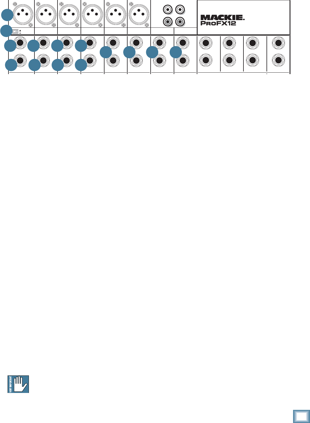
13
Owner’s Manual
Owner’s Manual
Front Panel Features
Connection Section
This is where you plug things in: microphones, line-
level instruments and effects, headphones, and the
ultimate destination for your sound: PA system, stage
monitors, effects processors, CD player/recorder, etc.
See Appendix B for further details and drawings of
the connectors you can use with the ProFX mixer.
6. MIC INPUTS
We use phantom-powered, balanced microphone
inputs just like the big studio mega-consoles, for exactly
the same reason: This kind of circuit is excellent at re-
jecting hum and noise. You can plug in almost any kind
of mic that has a standard XLR male mic connector.
Professional ribbon, dynamic, and condenser mics will
all sound excellent through these inputs. The ProFX
mixer’s mic inputs will handle any kind of mic level
you can toss at them, without overloading. Be sure to
perform the gain-setting procedure on page 3.
PHANTOM POWER
Most modern professional condenser mics require
phantom power, which lets the mixer send low-cur-
rent DC voltage to the mic’s electronics through the
same wires that carry audio. (Semi-pro condenser mics
often have batteries to accomplish the same thing.)
“Phantom” owes its name to an ability to be “unseen”
by dynamic mics (Shure SM57/SM58, for instance),
which don’t need external power and aren’t affected by
it anyway.
The ProFX mixer’s phantom power is globally
controlled by the phantom power switch [32]. (This
means that phantom power for all the mic inputs is
turned on and off together.)
Never plug single-ended (unbalanced) micro-
phones, or ribbon microphones into the mic
input jacks if phantom power is on. Do not
plug instrument outputs into the mic input jacks with
phantom power on unless you know for certain it is safe
to do so.
7. LINE/HI-Z SWITCH
To connect a guitar directly to the mixer without us-
ing a DI Box, press this switch in fi rst, then connect the
output from your guitar to channel 1's 1⁄4" TRS input
[8]. The input impedance is then optimized for direct
connection, and high-frequency fi delity is assured.
In the out position, channel 1's 1⁄4" TRS input be-
comes a line input just like the other mono line inputs
[9].
To use guitars or other instruments on other chan-
nels, you will need to use an external DI box fi rst.
Without the DI box, (or if this switch is not pressed in)
guitars may sound dull and muddy.
8. LINE/HI-Z INPUT (Channel 1 only)
This 1/4" jack shares circuitry (but not phantom
power) with the mic preamp, and can be driven by bal-
anced or unbalanced sources.
To connect a balanced line to this input, use a 1⁄4"
Tip-Ring-Sleeve (TRS) plug.
To connect an unbalanced line to this input, use a 1⁄4"
mono (TS) phone plug or instrument cable.
This line-level input can also accept instrument-level
signals if the hi-z switch [7] is pressed in. This allows
you to connect guitars directly into channel 1 without
the need for a DI box.
TAPE
IN
ST RETURN MAIN OUT PHONES
FOOTSWITCH
TAP E
OUT
L
R
L
(UNBALANCED)
R
FX SEND
LINE IN 4
INSERT
BAL /
UNBAL
(MONO) (MONO) (MONO) (MONO)
LINE IN 7
LINE IN 8
BAL /
UNBAL LINE IN 9
MIC MIC MIC MIC MIC MIC
L
R
(MONO)
LINE IN 5
LINE IN 6
BAL /
UNBAL
L
R
LINE IN 10
BAL /
UNBAL
L
R
LINE IN 11
LINE IN 12
BAL /
UNBAL
L
R
BAL /
UNBAL
L
R
BAL /
UNBAL
L
R
MON SEND
BAL /
UNBAL
BAL /
UNBAL
4
LINE IN 3
INSERT
BAL /
UNBAL
3
LINE IN 2
INSERT
BAL /
UNBAL
BAL /
UNBAL
2
LINE/HI-Z IN 1
INSERT
1 5/6 7/8 9/10 11/12
LINE
HI-Z
PROFESSIONAL MIC/LINE MIXER WITH FX
7
6
8
11
9 9 9 10 10 10
11 11 11 10
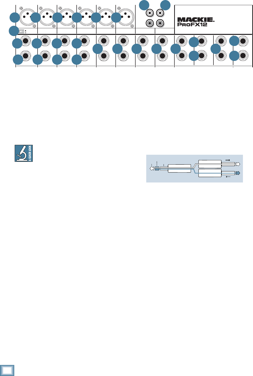
14
ProFX8 and ProFX12
ProFX8 and ProFX12
The insert point is after the gain control [20], level
set LED [21], and low cut switch [22], but before the
channel EQ [23-25] and fader [31]. The channel signal
can go out of the insert jack to an external device, be
processed (or whatever) and come back in on the same
insert jack. To do this requires a special insert cable
that must be wired thusly:
Tip = send (output to effects device)
Ring = return (input from effects device)
Sleeve = common ground
Insert jacks can be used as channel direct outputs;
post-gain, and pre-EQ. See the connector section on
page 28 (fi gure F) showing three ways to use insert con-
nections.
12. STEREO RETURN
This is where you connect the outputs of your parallel
effects devices (or extra audio sources). The circuits
will handle stereo or mono, balanced or unbalanced sig-
nals. They can be used with just about any pro or semi-
pro effects device or line-level source on the market.
The signals coming into these inputs can be adjusted
using the stereo return [45] fader before passing onto
the main mix bus (see page 23). Signals coming in here
can also be quickly muted with the mute switch [44],
and the OL LED [43] will show you if your incoming
signal is too high.
Stereo Device: If you have a stereo parallel effects
device (two cords), use stereo return left and right.
Mono Device: If you have an effects device with a
mono output (one cord), plug that into the stereo
return left/mono, and leave the right unplugged. The
signal will be sent to both sides, magically appearing in
the center as a mono signal.
9. MONO LINE INPUTS
These 1/4" jacks share circuitry (but not phantom
power) with the mic preamps, and can be driven by bal-
anced or unbalanced sources.
To connect balanced lines to these inputs, use a 1⁄4"
Tip-Ring-Sleeve (TRS) plug.
To connect unbalanced lines to these inputs, use a
1⁄4" mono (TS) phone plug or instrument cable.
If you have a stereo source, and the stereo
and hybrid channels are in use, you can use
two mono channels. Traditionally, an odd-
numbered channel receives the left signal. For
example, you could feed the ProFX mixer a stereo signal
by inserting the device’s left output plug into the chan-
nel 1 jack (pan fully left), and its right output plug into
the channel 2 jack (pan fully right).
10. STEREO LINE INPUTS
These 1/4" jacks can be driven by stereo or mono,
balanced or unbalanced sources. They can be used with
just about any professional or semi-pro instrument, ef-
fect or tape player.
To connect balanced lines to these inputs, use a 1⁄4"
Tip-Ring-Sleeve (TRS) plug.
To connect unbalanced lines to these inputs, use a
1⁄4" mono (TS) phone plug or instrument cable.
If you just have a mono source, plug it into the left
input (labeled mono), and the signal will appear (as if
by magic) equally on the left and right of the main mix.
11. CHANNEL INSERT
These unbalanced 1/4" jacks are for connecting serial
effects processors such as compressors, equalizers, de-
essers, or fi lters.
We’ve included inserts for just the mono channels. If
you want to use this kind of processing on other chan-
nels, simply patch through the processor before you plug
into the ProFX mixer.
TAPE
IN
ST RETURN MAIN OUT PHONES
FOOTSWITCH
TAP E
OUT
L
R
L
(UNBALANCED)
R
FX SEND
LINE IN 4
INSERT
BAL /
UNBAL
(MONO) (MONO) (MONO) (MONO)
LINE IN 7
LINE IN 8
BAL /
UNBAL LINE IN 9
MIC MIC MIC MIC MIC MIC
L
R
(MONO)
LINE IN 5
LINE IN 6
BAL /
UNBAL
L
R
LINE IN 10
BAL /
UNBAL
L
R
LINE IN 11
LINE IN 12
BAL /
UNBAL
L
R
BAL /
UNBAL
L
R
BAL /
UNBAL
L
R
MON SEND
BAL /
UNBAL
BAL /
UNBAL
4
LINE IN 3
INSERT
BAL /
UNBAL
3
LINE IN 2
INSERT
BAL /
UNBAL
BAL /
UNBAL
2
LINE/HI-Z IN 1
INSERT
1 5/6 7/8 9/10 11/12
LINE
HI-Z
PROFESSIONAL MIC/LINE MIXER WITH FX
7
6
8
11
9 9 9 10 10 10
11 11 11 10 12 13 15 16
17
14
6 6 6 6 6 18 19
“tip”
This plug connects to one of the
mixer’s Channel Insert jacks. “ring”
tip ring sleeve
SEND to processor
RETURN from processor
(TRS plug)

15
Owner’s Manual
Owner’s Manual
13. MON SEND
Stage monitors allow the talented musicians in your
band to hear themselves clearly on stage, and this can
often be a good thing. The monitor mix can be care-
fully adjusted in level using the aux mon controls [26].
These tap a portion of each channel's signal to provide
a 1/4" TRS output here to feed external stage monitors.
These could either be passive stage monitors powered
by an external amplifi er, or powered stage monitors with
their own amplifi er built in.
The monitor signal is the sum (mix) of all the chan-
nels whose aux mon control is set to more than mini-
mum. If they want "more me, and less Keith," you can
turn up their channel's aux mon control, and turn down
Keith's.
The overall output level can be adjusted with the
monitor fader [47] and its EQ tweaked with the graphic
EQ [37] if the main mix/mon switch [38] is pressed in.
Alternatively, you could add an external graphic EQ be-
tween this output and your powered monitors. This will
allow you to adjust the EQ, and minimize the chance of
feedback from nearby microphones.
The monitor output is not affected by the main fader
[48], or the channel faders [31]. This allows you to set
up the monitor mix and level just right, and not have it
change when a channel fader or the main mix fader is
adjusted. This is known as "pre-fader."
14. FX SEND
This 1/4" TRS line-level output can be used to feed an
external effects processor (FX), such as a nice sound ef-
fect, or delay unit. The output from this jack is an exact
copy of what goes into the internal FX processor, being
the careful mix of all channels whose aux FX control
[14] is turned more than minimum.
(The processed output of the internal FX does not
come out of this output, but is added internally to the
main mix or monitor mix.)
The overall output level can be adjusted with the FX
master knob [52]. (This knob also effects the level go-
ing into the internal FX.)
The output is "post-fader," so any changes to the chan-
nel faders [31] will also affect the level going to the
external processor.
The processed output from the effects processor is
usually returned to the stereo returns [12] or a spare
channel, and you can carefully mix the original unpro-
cessed channel (dry) and the processed channel (wet).
Altering the original channel fader increases both the
wet and dry signals and keeps them at the same delicate
ratio. (For example, the reverb remains at the same
level relative to the original.)
15. 1⁄4" MAIN OUTS
These outputs feed the main mix out into the waiting
world. You can feed your amplifi ers this way, or through
the XLR main outputs [4].
To use these outputs to drive balanced inputs, con-
nect 1⁄4" TRS (Tip–Ring–Sleeve) phone plugs like this:
Tip = + (hot)
Ring = –(cold)
Sleeve = Ground
To use these outputs to drive unbalanced inputs, con-
nect 1⁄4" TS (Tip-Sleeve) phone plugs like this:
Tip = + (hot)
Sleeve = Ground
16. FX FOOTSWITCH
This 1/4" TRS connector is where you can connect
your favorite footswitch. This will allow you to easily
mute or un-mute the internal effects, while stamping
your foot and looking like you were mad about some-
thing. Any one-button on/off footswitch will work.
If the internal effects have already been muted with
the internal FX mute switch [51] then the footswitch
has no effect, but you can still stamp your foot and pout
if that helps any. Cultivate that bad-boy image.
17. PHONES
This 1/4" TRS stereo jack will drive any standard head-
phone to very loud levels. The wiring follows standard
conventions:
Tip = Left channel
Ring = Right channel
Sleeve = Common ground
The headphones output is the stereo main mix, not
affected by the main fader [48], or the graphic EQ [37].
Warning: when we say the headphone out-
put is loud, we’re not kidding. It can cause
permanent ear damage. Even intermediate
levels may be painfully loud with some earphones. Be
careful! Always turn the phones level control [42] all
the way down before connecting headphones, adding
new sources, or making any other changes. Keep it down
until you’ve put the phones on. Then turn it up slowly.
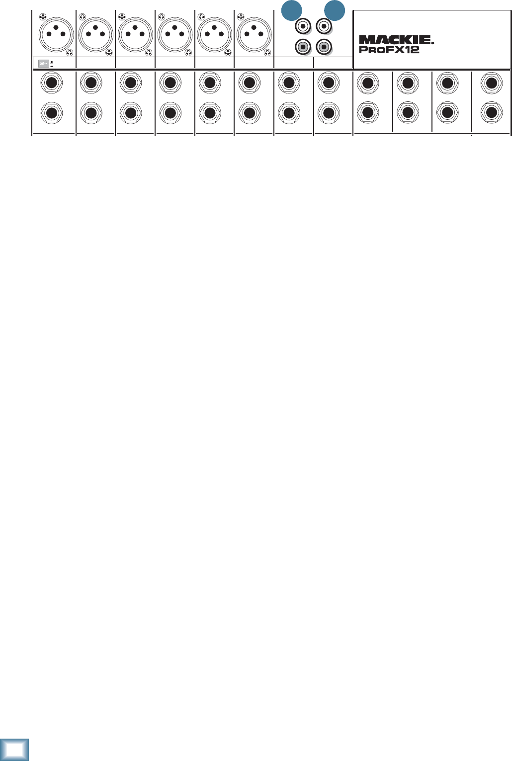
16
ProFX8 and ProFX12
ProFX8 and ProFX12
18. TAPE INPUT
These stereo unbalanced RCA inputs are designed to
work with semipro as well as pro player/recorders. You
can also connect any standard source with an unbal-
anced line-level output, such as a CD or DVD player,
iPod dock, and so on.
Connect your source’s line-level outputs here, using
good quality hi-fi (RCA) cables.
You can use these with a tape or CD player to feed
music to a PA system between sets, when the break
switch [35] is engaged. The level coming into the mixer
can be adjusted with the tape level knob [36]. For ex-
ample, you could press the break switch to mute all the
other channels at once, then play your tape or CD player
and bring up its level slowly.
19. TAPE OUTPUTS
These stereo unbalanced RCA outputs allow you to
record the main stereo mix onto a tape deck, hard disk
recorder, automatic CD burner, or a computer, etc. This
allows you to make a recording for posterity/archive/
legal purposes whenever the band gets back together
again.
The tape output is the stereo main mix, not affected
by the main fader [48], or the graphic EQ [37].
TAPE
IN
ST RETURN MAIN OUT PHONES
FOOTSWITCH
TAP E
OUT
L
R
L
(UNBALANCED)
R
FX SEND
LINE IN 4
INSERT
BAL /
UNBAL
(MONO) (MONO) (MONO) (MONO)
LINE IN 7
LINE IN 8
BAL /
UNBAL LINE IN 9
MIC MIC MIC MIC MIC MIC
L
R
(MONO)
LINE IN 5
LINE IN 6
BAL /
UNBAL
L
R
LINE IN 10
BAL /
UNBAL
L
R
LINE IN 11
LINE IN 12
BAL /
UNBAL
L
R
BAL /
UNBAL
L
R
BAL /
UNBAL
L
R
MON SEND
BAL /
UNBAL
BAL /
UNBAL
4
LINE IN 3
INSERT
BAL /
UNBAL
3
LINE IN 2
INSERT
BAL /
UNBAL
BAL /
UNBAL
2
LINE/HI-Z IN 1
INSERT
1 5/6 7/8 9/10 11/12
LINE
HI-Z
PROFESSIONAL MIC/LINE MIXER WITH FX
18 19
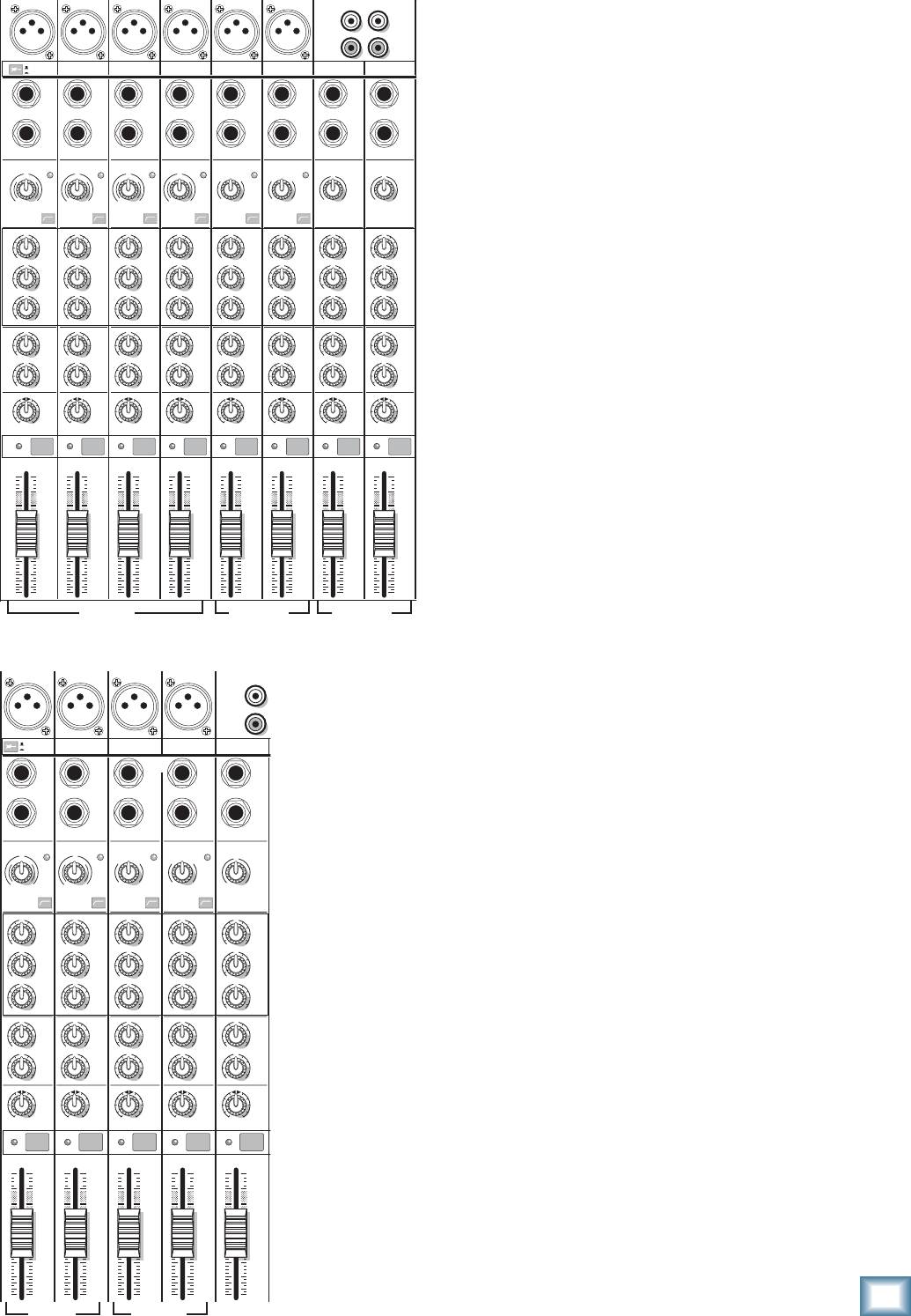
17
Owner’s Manual
Owner’s Manual
Channel Controls
The vertical channel strips look very similar, with only
a few differences between them. Each channel works
independently, and just controls the signals plugged into
the inputs directly above it. There are three different
fl avors of channel strip: Mono, Hybrid, and Stereo.
Mono Channels (1–4 on ProFX12)
(1, 2 on ProFX8)
• The mono channel controls affect both the
mono mic input and the mono line-level input.
• The gain knob adjusts both mic and line inputs.
• Each mono channel has an insert jack and low
cut switch.
• Channel 1 has a hi-z switch so you can connect
a guitar directly.
• The 3-band EQ has shelving high, shelving low,
and peaking mid EQ.
Hybrid Channels (5/6, 7/8 on ProFX12)
(3/4, 5/6 on ProFX8)
• Except for gain and low cut, these controls
affect the mono mic input and the stereo line-
level input.
• The gain knob adjusts the mic input only. (The
stereo line inputs are fi xed at unity gain.)
• The low cut switch only affects the mic input.
• The mono mic input is split equally to the left
and right.
• The hybrid channel EQ is a 3-band design just
like the mono channel EQ.
Stereo Channels (9/10, 11/12 on ProFX12)
(7/8 on ProFX8)
• These controls affect the stereo line-level
inputs.
• The gain knob adjusts the left and right line
inputs equally. There is no level set LED or low
cut switch.
• The stereo channel EQ is a 3-band design just
like the mono channel EQ.
“U” LIKE UNITY GAIN
Mackie mixers have a “U” symbol on almost every level
control. This “U” stands for “unity gain,” meaning no
change in signal level (0 dB gain). Once you have ad-
justed the input signal with the gain control, you can set
every control at “U” and your signals will travel through
the mixer at optimal levels. What’s more, all the labels
on our level controls are measured in decibels (dB), so
you’ll know what you’re doing level-wise if you choose to
change a control’s settings.
TAPE
IN
TAPE
OUT
L
R
L
(UNBALANCED)
R
MID
2.5kHz
MID
2.5kHz
MID
2.5kHz
MID
2.5kHz
MID
2.5kHz
80Hz
LOW
U
+15-15
U
+15-15
U
+15-15
LINE IN 4
INSERT
RL
LOW CUT
100 Hz
U
GAIN
M
I
C
G
A
I
N
U+50
-20dB +30dB
4
12kHz
HI
MID
2.5kHz
80Hz
LOW
U
+15-15
U
+15-15
U
+15-15
12kHz
HI
MID
2.5kHz
80Hz
LOW
U
+15-15
U
+15-15
U
+15-15
12kHz
HI
MID
2.5kHz
80Hz
LOW
U
+15-15
U
+15-15
U
+15-15
12kHz
HI
PAN
AUX
U
+15
OO
MON
FX
U
+15
OO
RL
PAN
AUX
U
+15
OO
MON
FX
U
+15
OO
RL
PAN
AUX
U
+15
OO
MON
FX
U
+15
OO
RL
PAN
AUX
U
+15
OO
MON
FX
U
+15
OO
80Hz
LOW
U
+15-15
U
+15-15
U
+15-15
RL
LOW CUT
100 Hz
12kHz
HI
PAN
AUX
U
+15
OO
MON
FX
U
+15
OO
80Hz
LOW
U
+15-15
U
+15-15
U
+15-15
BAL /
UNBAL
(MONO) (MONO) (MONO)
LINE IN 7
LINE IN 8
BAL /
UNBAL LINE IN 9
RL
LOW CUT
100 Hz
GAIN
7/85/6
12kHz
HI
PAN
AUX
U
+15
OO
MON
FX
U
+15
OO
80Hz
LOW
U
+15-15
U
+15-15
U
+15-15
RL
M
I
C
G
A
I
N
U+50
GAIN
M
I
C
G
A
I
N
U+50
9/10
12kHz
HI
LEVEL
SET
LEVEL
SET
LEVEL
SET
LOW CUT
100 Hz
U
GAIN
M
I
C
G
A
I
N
U+50
-20dB +30dB
LEVEL
SET
LEVEL
SET
LEVEL
SET
LOW CUT
100 Hz
U
GAIN
M
I
C
G
A
I
N
U+50
-20dB +30dB
LOW CUT
100 Hz
U
GAIN
M
I
C
G
A
I
N
U+50
-20dB +30dB
PAN
AUX
U
+15
OO
MON
FX
U
+15
OO
GAIN
MIC MIC MIC MIC MIC MIC
80Hz
LOW
U
+15-15
U
+15-15
U
+15-15
U
+20-20
GAIN
U
+20-20
RL
11/12
EQEQEQEQ EQ EQ EQ EQ
12kHz
HI
PAN
AUX
U
+15
OO
MON
FX
U
+15
OO
dB
30
20
10
10
OO
40
50
5
5
U
60
dB
30
20
10
10
OO
40
50
5
5
U
60
dB
30
20
10
10
OO
40
50
5
5
U
60
dB
30
20
10
10
OO
40
50
5
5
U
60
dB
30
20
10
10
OO
40
50
5
5
U
60
dB
30
20
10
10
OO
40
50
5
5
U
60
dB
30
20
10
10
OO
40
50
5
5
U
60
dB
30
20
10
10
OO
40
50
5
5
U
60
L
R
(MONO)
LINE IN 5
LINE IN 6
BAL /
UNBAL
L
R
LINE IN 10
BAL /
UNBAL
L
R
LINE IN 11
LINE IN 12
BAL /
UNBAL
L
R
4
LINE IN 3
INSERT
3
BAL /
UNBAL
3
LINE IN 2
INSERT
2
BAL /
UNBAL
BAL /
UNBAL
2
LINE/HI-Z IN 1
INSERT
1 5/6 7/8 9/10 11/12
LINE
HI-Z
1
OL OL OL OL OL OL OL OL
MUTE MUTE MUTE MUTE MUTE MUTE MUTE MUTE
TAPE
IN
L
R
(UNBAL
A
MID
2.5kHz
MID
2.5kHz
MID
2.5kHz
MID
2.5kHz
MID
2.5kHz
80Hz
LOW
U
+15-15
U
+15-15
U
+15-15
INSERT
RL
LOW CUT
100 Hz
U
GAIN
M
I
C
G
A
I
N
U+50
-20dB +30dB
OL
1
EQ
12kHz
HI
PAN
AUX
U
+15
OO
MON
FX
U
+15
OO
80Hz
LOW
U
+15-15
U
+15-15
U
+15-15
RL
LOW CUT
100 Hz
U
GAIN
M
I
C
G
A
I
N
U+50
-20dB +30dB
2
EQ
12kHz
HI
PAN
AUX
U
+15
OO
MON
FX
U
+15
OO
80Hz
LOW
U
+15-15
U
+15-15
U
+15-15
LINE IN 2 LINE/HI-Z IN 1
INSERT
BAL /
UNBAL
(MONO) (MONO) (MONO)
LINE IN 3
LINE IN 4
BAL /
UNBAL LINE IN 5
RL
LOW CUT
100 Hz
GAIN
3/4
EQ
12kHz
HI
PAN
AUX
U
+15
OO
MON
FX
U
+15
OO
80Hz
LOW
U
+15-15
U
+15-15
U
+15-15
RL
LOW CUT
100Hz
GAIN
M
I
C
G
A
I
N
U+50
M
I
C
G
A
I
N
U+50
5/6
EQ
12kHz
HI
LEVEL
SET
LEVEL
SET
LEVEL
SET
LEVEL
SET
PAN
AUX
U
+15
OO
MON
FX
U
+15
OO
GAIN
MIC MIC MIC MIC
80Hz
LOW
U
+15-15
U
+15-15
U
+15-15
U
+20-20
RL
7/8
EQ
12kHz
HI
PAN
AUX
U
+15
OO
MON
FX
U
+15
OO
dB
30
20
10
10
OO
40
50
5
5
U
60
dB
30
20
10
10
OO
40
50
5
5
U
60
dB
30
20
10
10
OO
40
50
5
5
U
60
dB
30
20
10
10
OO
40
50
5
5
U
60
dB
30
20
10
10
OO
40
50
5
5
U
60
L
R
LINE IN 6
BAL /
UNBAL
L
R
LINE IN 7
LINE IN 8
BAL /
UNBAL
L
R
OL OL OL OL
1 2 3/4 5/6 7/8
LINE
HI-Z
LINE
HI-Z
MUTE MUTE MUTE MUTE MUTE
MONO HYBRID STEREO
MONO HYBRID STEREO
ProFX12
ProFX8
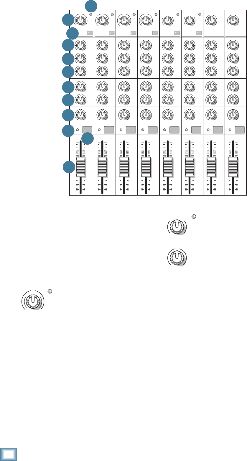
18
ProFX8 and ProFX12
ProFX8 and ProFX12
For hybrid channels (mic input and
stereo line input), the gain control just
affects the microphone input.
For stereo channels (no mic input) the
gain control just affects the line-level
inputs, with 20 dB of gain, and 20 dB of
attenuation. There is no level set LED.
21. LEVEL SET LED
These LEDs are used with the gain control [20] to set
the channel preamplifi er gain just right for each source.
If you hear distortion on one or more of your channels,
check the level set LEDs are not on continuously, and
turn down the gain if they are.
22. LOW CUT
Each channel with a mic input has a low cut switch
that cuts the bass frequencies below 100 Hz, at a rate
of 18 dB per octave. All mic inputs are affected, and the
line inputs of the mono channels.
We recommend that you use low cut on every micro-
phone application except kick drum, bass guitar, and
bassy synth patches. These aside, there isn’t much down
there that you want to hear, and fi ltering it out makes
the low stuff you do want much more crisp and tasty.
Not only that, low cut can help reduce the possibility
of feedback in live situations and help to conserve the
amplifi er power.
20. GAIN
If you haven’t already, please read the gain-setting
procedure on page 3. The gain adjustment allows all
your various source signals from the outside world to be
adjusted to the same optimal internal operating levels.
Setting the gain correctly will ensure that the pre-
amplifi er’s gain is not too high, where distortion could
occur, and not too low, where your quieter, exquisitely-
delicate passages might be lost in background noise.
For mono channels (mic input with a
mono line input), the gain knob adjusts
the input sensitivity of the mic and line
inputs.
Adjust the gain control so the level set LEDs [21]
come on occasionally during the louder moments of your
playing or singing, and go off when you stop.
If the signal comes through the mic XLR jack, there
will be 0 dB of gain (U for unity) with the knob fully
down, ramping to 50 dB of gain fully up.
Through the 1⁄4" mono input, there is 20 dB of
attenuation fully down and 30 dB of gain fully up,
with a “U” (unity gain) mark at 12:00. This 20 dB of
attenuation can be very handy when you are inserting
a very hot signal, need to add a lot of EQ boost, or both.
Without this “virtual pad,” this scenario might lead to
channel clipping.
MID
2.5kHz
MID
2.5kHz
MID
2.5kHz
MID
2.5kHz
MID
2.5kHz
80Hz
LOW
U
+15-15
U
+15-15
U
+15-15
RL
LOW CUT
100 Hz
U
GAIN
M
I
C
G
A
I
N
U+50
-20dB +30dB
4
12kHz
HI
MID
2.5kHz
80Hz
LOW
U
+15-15
U
+15-15
U
+15-15
12kHz
HI
MID
2.5kHz
80Hz
LOW
U
+15-15
U
+15-15
U
+15-15
12kHz
HI
MID
2.5kHz
80Hz
LOW
U
+15-15
U
+15-15
U
+15-15
12kHz
HI
PAN
AUX
U
+15
OO
MON
FX
U
+15
OO
RL
PAN
AUX
U
+15
OO
MON
FX
U
+15
OO
RL
PAN
AUX
U
+15
OO
MON
FX
U
+15
OO
RL
PAN
AUX
U
+15
OO
MON
FX
U
+15
OO
80Hz
LOW
U
+15-15
U
+15-15
U
+15-15
RL
LOW CUT
100 Hz
12kHz
HI
PAN
AUX
U
+15
OO
MON
FX
U
+15
OO
80Hz
LOW
U
+15-15
U
+15-15
U
+15-15
RL
LOW CUT
100 Hz
GAIN
7/85/6
12kHz
HI
PAN
AUX
U
+15
OO
MON
FX
U
+15
OO
80Hz
LOW
U
+15-15
U
+15-15
U
+15-15
RL
M
I
C
G
A
I
N
U+50
GAIN
M
I
C
G
A
I
N
U+50
9/10
12kHz
HI
LEVEL
SET
LEVEL
SET
LEVEL
SET
LOW CUT
100 Hz
U
GAIN
M
I
C
G
A
I
N
U+50
-20dB +30dB
LEVEL
SET
LEVEL
SET
LEVEL
SET
LOW CUT
100 Hz
U
GAIN
M
I
C
G
A
I
N
U+50
-20dB +30dB
LOW CUT
100 Hz
U
GAIN
M
I
C
G
A
I
N
U+50
-20dB +30dB
PAN
AUX
U
+15
OO
MON
FX
U
+15
OO
GAIN
80Hz
LOW
U
+15-15
U
+15-15
U
+15-15
U
+20-20
GAIN
U
+20-20
RL
11/12
EQEQEQEQ EQ EQ EQ EQ
12kHz
HI
PAN
AUX
U
+15
OO
MON
FX
U
+15
OO
dB
30
20
10
10
OO
40
50
5
5
U
60
dB
30
20
10
10
OO
40
50
5
5
U
60
dB
30
20
10
10
OO
40
50
5
5
U
60
dB
30
20
10
10
OO
40
50
5
5
U
60
dB
30
20
10
10
OO
40
50
5
5
U
60
dB
30
20
10
10
OO
40
50
5
5
U
60
dB
30
20
10
10
OO
40
50
5
5
U
60
dB
30
20
10
10
OO
40
50
5
5
U
60
321
OL OL OL OL OL OL OL OL
MUTE MUTE MUTE MUTE MUTE MUTE MUTE MUTE
20 21
22
23
24
25
26
27
28
29 30
31
GAIN
U
+20-20
GAIN
M
I
C
G
A
I
N
U+50
LEVEL
SET
LEVEL
SET
U
GAIN
M
I
C
G
A
I
N
U+50
-20dB +30dB
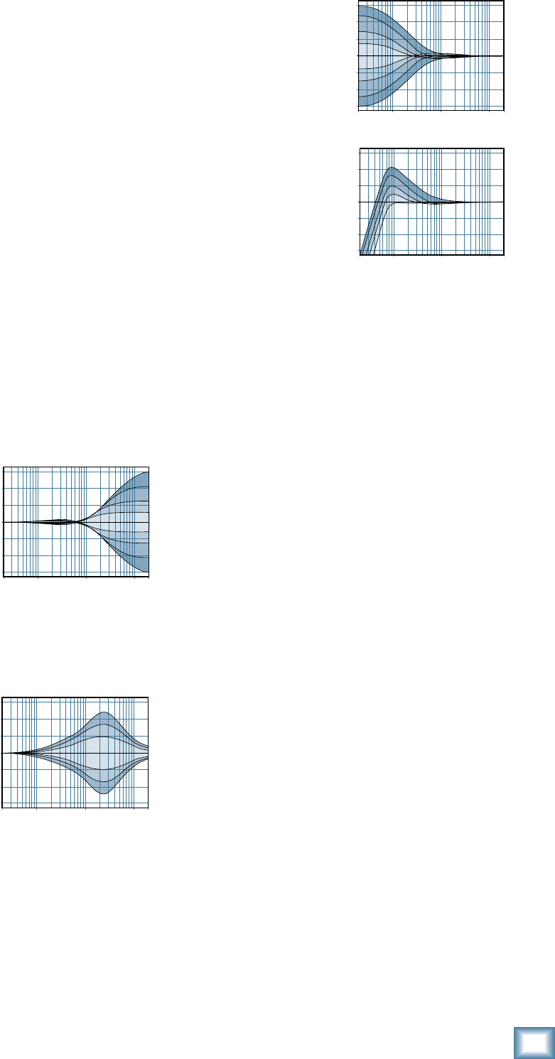
19
Owner’s Manual
Owner’s Manual
Another way to consider low cut’s function is that it
actually adds fl exibility during live performances. With
the addition of low cut, you can safely use low EQ on
vocals. Many times, bass shelving EQ can really ben-
efi t voices. Trouble is, adding low EQ also boosts stage
rumble, mic handling clunks and breath pops. Low cut
removes all these problems so you can add low EQ with-
out losing a woofer out the window.
3-BAND EQ
The ProFX mixer has 3-band equalization at carefully
selected points — low shelving at 80 Hz, mid peaking at
2.5 kHz, and high shelving at 12 kHz. “Shelving” means
that the circuitry boosts or cuts all frequencies past the
specifi ed frequency. For example, rotating the low EQ
knob 15 dB to the right boosts bass starting at 80 Hz and
continuing down to the lowest note you never heard.
“Peaking” means that certain frequencies form a “hill”
around the center frequency — 2.5 kHz in the case of
the mid EQ.
The following graphs of frequency vs. signal level show
the approximate overall effect of EQ adjustment on the
frequency range.
23. HI EQ
This control gives you
up to 15 dB boost or cut
above 12 kHz, and it is fl at
(no boost or cut) at the
detent. Use it to add sizzle
to cymbals, and an overall
sense of transparency, or
edge to keyboards, vocals,
guitar and bacon frying. Turn
it down a little to reduce sibilance, or to hide tape hiss.
24. MID EQ
Short for “midrange,”
this knob provides 15 dB
of boost or cut, centered at
2.5 kHz, also fl at at the cen-
ter detent. Midrange EQ
is often thought of as the
most dynamic, because the
frequencies that defi ne any
particular sound are almost always found in this range.
You can create many interesting and useful EQ changes
by turning this knob down as well as up.
25. LOW EQ
This control gives you up
to 15 dB boost or cut below
80 Hz. The circuit is fl at at
the center detent position.
This frequency represents
the punch in bass drums,
bass guitar, fat synth
patches, and some really
serious male singers.
Used in conjunction with
the low cut [22] switch,
you can boost the low EQ
without injecting a ton of
subsonic debris into the
mix.
MODERATION DURING EQ
With EQ, you can also upset things royally. We’ve de-
signed a lot of boost and cut into each equalizer circuit,
because we know everyone will occasionally need that.
But if you max the EQs on every channel, you’ll get mix
mush. Equalize subtly and use the left sides of the knobs
(cut), as well as the right (boost). Very few gold-record-
album engineers ever use more than about 3 dB of EQ.
If you need more than that, there’s usually a better way
to get it, such as placing a mic differently (or using a
different kind of mic entirely).
26. AUX MON
These knobs tap a portion of each channel's signal
to set up a nice monitor mix feeding stage monitors,
independent of the main mix. Adjust these controls on
each channel until your band is happy with the stage
monitor mix.
The aux mon feed from hybrid and stereo channels is
a mono sum of the left and right sides of these channels.
The controls are off when turned fully down, deliver
unity gain at the center detent, and can provide up to 15
dB of gain turned fully up.
The channel fader [31], pan [28], or mute [30] do
not affect the monitor output, but the other channel
controls will. (The aux mon is pre-fader.)
The monitor signal from the monitor output jack [13]
is the sum (mix) of all the channels whose aux mon
control is set to more than minimum. The overall output
level can be adjusted with the monitor fader [47] and
its EQ tweaked with the graphic EQ [37] if the main
mix/mon switch [38] is pressed in. Internal FX can also
be added to the monitor mix with the FX to mon knob
[54].
20Hz 100Hz 1kHz 10kHz 20kHz
–15
–10
–5
0
+5
+10
+15
Mid EQ
20Hz 100Hz 1kHz 10kHz 20kHz
–15
–10
–5
0
+5
+10
+15
20
Hz
100
Hz
1k
Hz
10k
Hz
20k
Hz
–15
–10
–5
0
+5
+10
+15
Low EQ with Low Cut
Low EQ
20
Hz
100
Hz
1k
Hz
10k
Hz
20k
Hz
–15
–10
–5
0
+5
+10
+15
High EQ
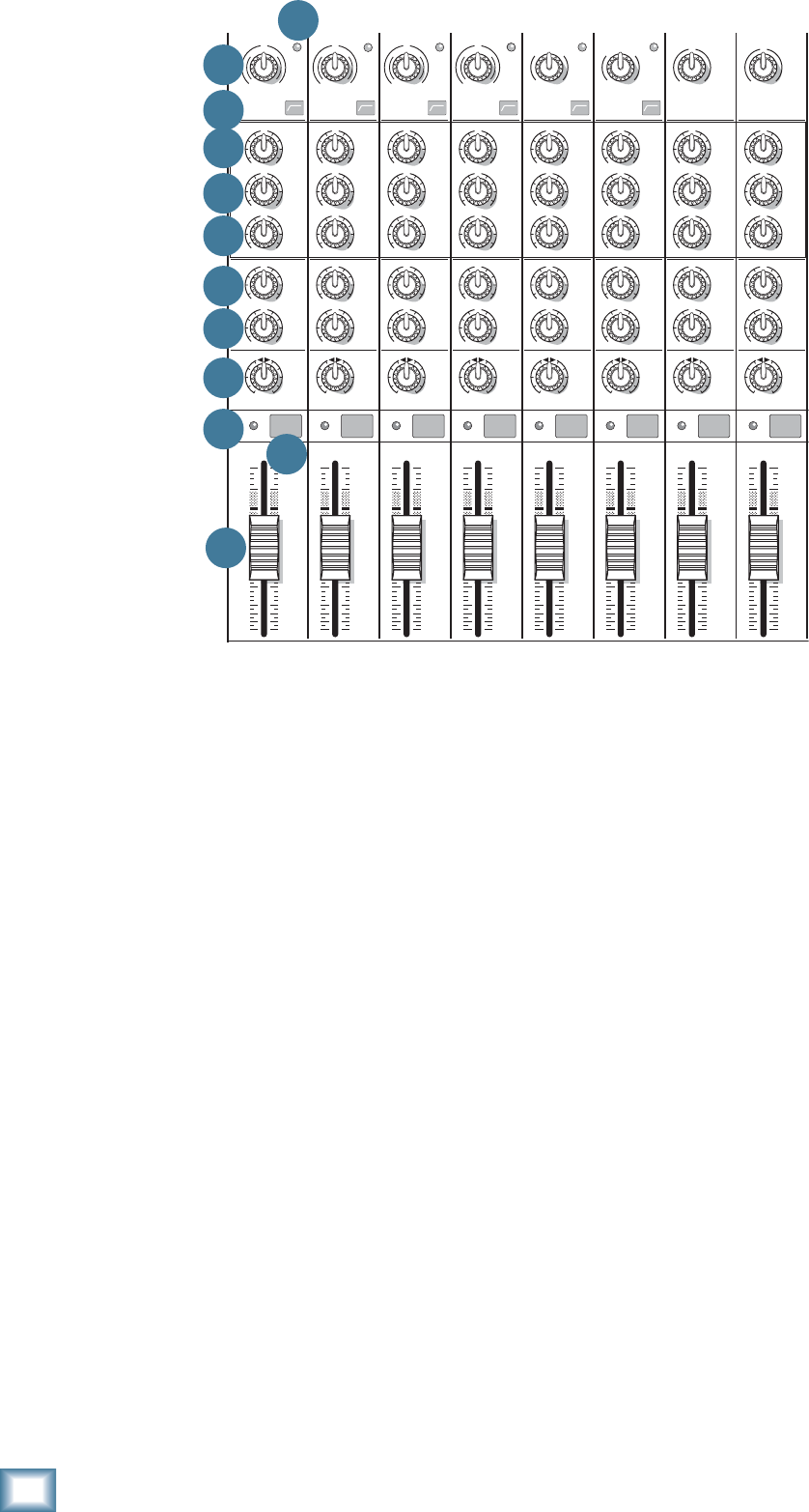
20
ProFX8 and ProFX12
ProFX8 and ProFX12
27. AUX FX
These knobs tap a portion of each channel's signal to
set up a nice FX mix feeding the internal FX processor,
and to feed external processors via the FX output [14].
The aux FX feed from hybrid and stereo channels is a
mono sum of the left and right sides of these channels.
The controls are off when turned fully down, deliver
unity gain at the center detent, and can provide up to 15
dB of gain turned fully up.
The channel fader [31], mute [30] and other channel
controls affect the FX output, but pan [28] does not.
The aux FX is post-fader.
The FX signal reaching the internal FX processor
and the FX send output jack, is the sum (mix) of all
the channels whose aux FX control is set to more than
minimum. The overall FX send level can be adjusted
with the FX master knob [52].
The FX signal from the internal FX processor is added
to the main mix using the FX return fader [46], and can
be added to the monitors with the FX to mon knob [54].
28. PAN
These knobs adjust the amount of channel signal sent
to the left versus the right outputs. On mono channels
these controls act as pan pots. On hybrid and stereo
channels, they work like the balance control on a home
stereo. They do not affect the aux mon or FX mixes.
29. OL LED
This LED will light if the channel signal is too high,
and this may cause distortion due to overloading.
The OL LED comes before the channel fader [31] in
the signal path, so the fader has no effect in your efforts
to turn off the OL LED.
Overloading may occur if the gain [20] is set too high,
so check that the level set LED [21] is not turning on
frequently. Turn down the gain if it is.
Overloading can also occur if the channel EQ [23-25]
is set too high. Check that the EQ settings are moderate.
Use the low cut switches [22] if the overloading is due
to lower unwanted bass thumps and bangs.
30. MUTE
Press this switch in to mute the channel in the main
mix. The aux mon output of the channel is not muted,
but the FX output to the internal FX processor and FX
send jack [14] is.
31. CHANNEL FADER
These faders control the channel’s level, from off, to
unity gain, on up to 10 dB of additional gain. The mono
channels have mono faders, and the hybrid and stereo
channels use stereo faders.
With the gain control [20] set correctly, the faders
should be set around unity gain (U).
MID
2.5kHz
MID
2.5kHz
MID
2.5kHz
MID
2.5kHz
MID
2.5kHz
80Hz
LOW
U
+15-15
U
+15-15
U
+15-15
RL
LOW CUT
100 Hz
U
GAIN
M
I
C
G
A
I
N
U+50
-20dB +30dB
4
12kHz
HI
MID
2.5kHz
80Hz
LOW
U
+15-15
U
+15-15
U
+15-15
12kHz
HI
MID
2.5kHz
80Hz
LOW
U
+15-15
U
+15-15
U
+15-15
12kHz
HI
MID
2.5kHz
80Hz
LOW
U
+15-15
U
+15-15
U
+15-15
12kHz
HI
PAN
AUX
U
+15
OO
MON
FX
U
+15
OO
RL
PAN
AUX
U
+15
OO
MON
FX
U
+15
OO
RL
PAN
AUX
U
+15
OO
MON
FX
U
+15
OO
RL
PAN
AUX
U
+15
OO
MON
FX
U
+15
OO
80Hz
LOW
U
+15-15
U
+15-15
U
+15-15
RL
LOW CUT
100 Hz
12kHz
HI
PAN
AUX
U
+15
OO
MON
FX
U
+15
OO
80Hz
LOW
U
+15-15
U
+15-15
U
+15-15
RL
LOW CUT
100 Hz
GAIN
7/85/6
12kHz
HI
PAN
AUX
U
+15
OO
MON
FX
U
+15
OO
80Hz
LOW
U
+15-15
U
+15-15
U
+15-15
RL
M
I
C
G
A
I
N
U+50
GAIN
M
I
C
G
A
I
N
U+50
9/10
12kHz
HI
LEVEL
SET
LEVEL
SET
LEVEL
SET
LOW CUT
100 Hz
U
GAIN
M
I
C
G
A
I
N
U+50
-20dB +30dB
LEVEL
SET
LEVEL
SET
LEVEL
SET
LOW CUT
100 Hz
U
GAIN
M
I
C
G
A
I
N
U+50
-20dB +30dB
LOW CUT
100 Hz
U
GAIN
M
I
C
G
A
I
N
U+50
-20dB +30dB
PAN
AUX
U
+15
OO
MON
FX
U
+15
OO
GAIN
80Hz
LOW
U
+15-15
U
+15-15
U
+15-15
U
+20-20
GAIN
U
+20-20
RL
11/12
EQEQEQEQ EQ EQ EQ EQ
12kHz
HI
PAN
AUX
U
+15
OO
MON
FX
U
+15
OO
dB
30
20
10
10
OO
40
50
5
5
U
60
dB
30
20
10
10
OO
40
50
5
5
U
60
dB
30
20
10
10
OO
40
50
5
5
U
60
dB
30
20
10
10
OO
40
50
5
5
U
60
dB
30
20
10
10
OO
40
50
5
5
U
60
dB
30
20
10
10
OO
40
50
5
5
U
60
dB
30
20
10
10
OO
40
50
5
5
U
60
dB
30
20
10
10
OO
40
50
5
5
U
60
321
OL OL OL OL OL OL OL OL
MUTE MUTE MUTE MUTE MUTE MUTE MUTE MUTE
20 21
22
23
24
25
26
27
28
29 30
31
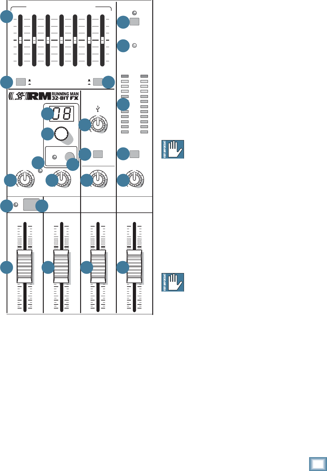
21
Owner’s Manual
Owner’s Manual
Master Controls
32. PHANTOM POWER SWITCH
If your microphones need phantom power, press in
this switch to add phantom power to all the XLR mi-
crophone inputs of the mixer. This lets the mixer send
low-current DC voltage to the mic’s electronics through
the same wires that carry audio. The LED will turn on as
a reminder that phantom power is engaged.
Most modern professional condenser mics require
phantom power. Semi-pro condenser mics often have
batteries to accomplish the same thing. “Phantom” owes
its name to an ability to be “unseen” by dynamic mics
(Shure SM57/SM58, for instance), which don’t need
external power and aren’t affected by it anyway.
Never plug single-ended (unbalanced) micro-
phones, or ribbon microphones into the mic
input jacks if phantom power is on. Do not
plug instrument outputs into the mic input jacks with
phantom power on, unless you know for certain it is safe
to do so.
33. POWER LED
This LED comes on when the mixer is plugged into
the AC mains supply, and the rear panel power switch
[3] is on.
If the LED does not turn on, make sure the AC power
is live, both ends of the power cord are correctly in-
serted, your electricity bill has been paid, and the lights
in town are on.
If you suspect the fuse is blown, disconnect
the power cord before removing and inspect-
ing the fuse located below the AC input.
34. METERS
These meters have 2 columns of 12 LEDs each, with
dB markings from –30 to +15, and OL (overload at +20
dBu). They indicate the stereo signal strength of the
main mix after the main fader [48].
Typically, you want to see these meters bouncing
between the “0” and the “+3” LEDs. It is okay if the OL
LEDs light occasionally, but if they light frequently or
continuously, turn down the main fader until they blink
occasionally or not at all.
Remember, audio meters are just tools to help assure
you that your levels are “in the ballpark.” You don’t have
to stare at them (unless you want to).
8K4K2K1K500250125
15
15
10
10
5
5
0
15
15
10
10
5
5
0
PHONES
STEREO GRAPHIC EQ
ST RTN FX RTN
U
+15
FX TO MON
FX MASTER
U
+15
OO
OO
dB
30
20
10
10
OO
40
50
5
5
U
60
dB
30
20
10
10
OO
40
50
5
5
U
60
dB
30
20
10
10
OO
40
50
5
5
U
60
dB
30
20
10
10
OO
40
50
5
5
U
60
PRESETS
FX PRESETS
01 BRIGHT ROOM
02 WARM LOUNGE
03 SMALL STAGE
04 WARM THEATER
05 WARM HALL
06 CONCERT HALL
13 DELAY 1 (300ms)
14 DELAY 2 (380ms)
15 DELAY 3 (480ms)
16 REVERB + DLY (250ms)
07 PLATE REVERB
08 CATHEDRAL
09 CHORUS
10 CHORUS + REV
11 DOUBLER
12 TAPE SLAP
MON MAIN
0dB=0dBu
MAIN
METERS
OL
4
6
3
10
15
7
10
20
30
0
2
BREAK
(MUTES ALL CHANNELS)
PHANTOM
POWER
POWER
OO
+20
U
TAPE LEVEL
OO
+20
U
USB THRU
OO
MAX
OL
OL
MAIN MIX
MON
EQ IN
BYPASS
RL
INPUT LEVEL
USB
MUTE
MUTE
48V
37
38 39
32
33
34
35
36425452
50
49
51
40
41
45 46 47 48
43 44
53
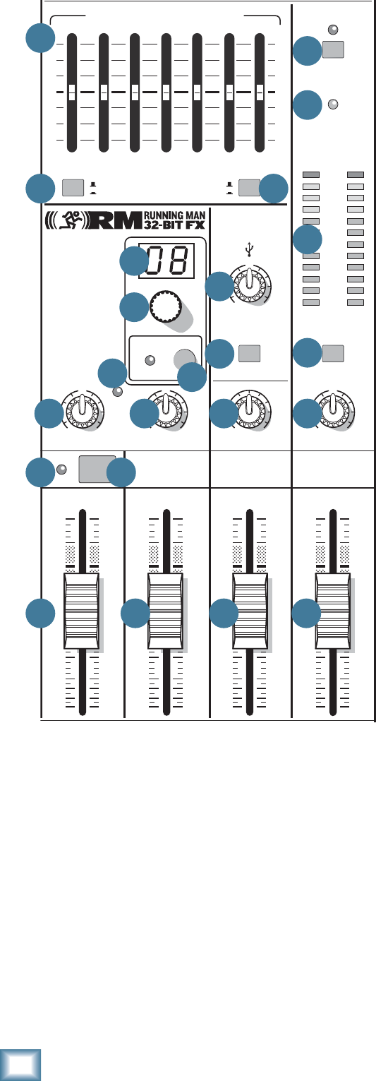
22
ProFX8 and ProFX12
ProFX8 and ProFX12
35. BREAK SWITCH
This important "take-a-break" switch quickly mutes
all the microphones and line-level inputs when the band
is between sets. This will prevent protestors or rogue
karaoke singers from storming the stage at the interval.
The monitor send [13] and FX send [14] are not af-
fected. Check this switch fi rst, if you are having trouble
with no sound in your system.
You can still play the stereo RCA tape inputs [18] in
the main stereo mix, and play audio coming in from your
computer via the USB inputs. For example, you could
play a soothing CD while the band is off stage.
36. TAPE LEVEL
This allows you to control the input level of signals
entering the tape inputs. It is conveniently close to the
break switch [35] so you can quickly mute all channels
and then bring up your background music when the
band is taking a break.
37. STEREO GRAPHIC EQ
This 7-band graphic equalizer adjusts the main mix
output. It affects the line-level outputs [4, 15], but not
the tape outputs [19], headphones [17], or the USB
output [5]. This EQ can be used for the monitor mix in-
stead of the main mix, if the main mix/mon switch [38]
is engaged. It can also be quickly bypassed using the EQ
in/bypass switch [39].
Each slider allows you to adjust the level of its
frequency band, with up to 15 dB of boost or cut, and
no change in level at the center (0 dB) position. The
frequency bands are: 125, 250, 500, 1k, 2k, 4k, and 8kHz.
The EQ section comes before the main fader [48],
and meters [34]. As with the channel EQ, just take it
easy. There is a large amount of adjustment, and if you
are not careful, you can upset the delicate balance of
nature. Although it may not seem cool to actually turn
down controls, with EQ it is often your best option. Turn
down the offending frequency range, rather than boost
the wanted range. You can use it to reduce the level of
some frequency bands where feedback occurs.
38. MAIN MIX/MON
This switch allows you to choose if the stereo graphic
EQ [37] is used for the stereo left and right main mix,
or if it is used for the monitors. For example, there
maybe times when the graphic EQ can be used wisely
in the monitor mix to reduce feedback in the monitors
from nearby microphones.
39. EQ IN/BYPASS
This switch allows you to quickly engage or disen-
gage the stereo graphic EQ. This can be used for quick
checks of your EQ settings, or to shorten the signal path
if you do not need to use the EQ.
40. USB INPUT LEVEL
This control lets you adjust the signal level of the two
channels coming in from your computer, via the USB
port, relative to the mix of the other channels. Adjust
it carefully to achieve the desired mix with the other
channels.
The USB input from your audio software such as
Tracktion, could be individual instrument tracks, a mix
of tracks, or processed tracks.
8K4K2K1K500250125
15
15
10
10
5
5
0
15
15
10
10
5
5
0
PHONES
STEREO GRAPHIC EQ
ST RTN FX RTN
U
+15
FX TO MON
FX MASTER
U
+15
OO
OO
dB
30
20
10
10
OO
40
50
5
5
U
60
dB
30
20
10
10
OO
40
50
5
5
U
60
dB
30
20
10
10
OO
40
50
5
5
U
60
dB
30
20
10
10
OO
40
50
5
5
U
60
PRESETS
FX PRESETS
01 BRIGHT ROOM
02 WARM LOUNGE
03 SMALL STAGE
04 WARM THEATER
05 WARM HALL
06 CONCERT HALL
13 DELAY 1 (300ms)
14 DELAY 2 (380ms)
15 DELAY 3 (480ms)
16 REVERB + DLY (250ms)
07 PLATE REVERB
08 CATHEDRAL
09 CHORUS
10 CHORUS + REV
11 DOUBLER
12 TAPE SLAP
MON MAIN
0dB=0dBu
MAIN
METERS
OL
4
6
3
10
15
7
10
20
30
0
2
BREAK
(MUTES ALL CHANNELS)
PHANTOM
POWER
POWER
OO
+20
U
TAPE LEVEL
OO
+20
U
USB THRU
OO
MAX
OL
OL
MAIN MIX
MON
EQ IN
BYPASS
RL
INPUT LEVEL
USB
MUTE
MUTE
48V
37
38 39
32
33
34
35
36425452
50
49
51
40
41
45 46 47 48
43 44
53

23
Owner’s Manual
Owner’s Manual
41. USB THRU
In addition to a mix of the other channels, the USB
output to your computer can contain any input from
your computer, if this switch is down. (This switch only
affects the output to your computer, not the headphones
or main mix.)
• If disengaged (out), the USB output to your
computer will just be the main mix. This is a
good position for overdubbing, as any playback
from your computer can be played in your main
speakers and headphones, while you play along
with a guitar and record only the guitar via
USB. This is also good for live recording, as a
safeguard against feedback. Here, the USB level
knob should also be down.
• If pressed in, the USB output to your computer
will be the main mix, including any audio
coming in from your computer. This is a good
position to record live performances where
playback of audio from the computer is also
part of the performance.
42. PHONES LEVEL
This controls the volume of the headphones output
from off to maximum gain.
Warning: The headphone amplifi er is de-
signed to drive any standard headphones to a
very loud level. It can cause permanent hear-
ing damage. Even intermediate levels may be painfully
loud with some headphones. Be careful! Always start
with the phones level control turned all the way down
before connecting headphones or making any connec-
tions. Keep it down until you’ve put on the headphones,
and turn it down fi rst whenever you play a new source or
instrument.
43. OL LED (for stereo return)
This LED will light if the signal coming into the stereo
return inputs [12] is too high, and this may cause dis-
tortion due to overloading.
The OL LED comes before the stereo return fader
[45], so the fader has no effect in your efforts to turn off
the OL LED.
Check your external processor or other device, and
turn down its level until the OL LED does not come on.
44. MUTE (for stereo returns)
Press this switch in to mute the signals coming into
the stereo return inputs [12].
45. STEREO RETURN FADER
Use this fader to lovingly adjust the level of any audio
coming into the stereo return inputs [12] from your
external processors or other equipment. The audio is
added to the main mix, and it can also be muted with
the stereo return mute switch [44].
Typically, this fader can just live at the unity U mark,
and the external device’s output control set at whatever
they call unity gain (check the manual of the effects
unit, CD player, drum machine, or whatever). If that
turns out to be too loud or too quiet, adjust the external
device’s outputs, not the mixer. That way, the mixer’s
faders are easy to relocate at the unity U mark. The
range is off to +10 dB.
46. FX RETURN FADER
Use this fader to gently adjust the level of the stereo
output from the internal FX processor being added to
the main mix. The range is off to +10 dB with unity at U.
47. MONITOR FADER
This fader controls the overall level of the monitor
send signal sent out to your stage monitors.
Adjust it carefully, and check that your band are
happy with the levels. The fader does not affect the
main mix level.
The monitor send signals are off with the fader fully
down, the “U” marking is unity gain, and fully up pro-
vides 10 dB of additional gain.
48. MAIN FADER
This fader controls the level of the main mix, and
affects the meters [34], and main line-level outputs
[4, 15]. The level adjustment occurs after the stereo
graphic EQ [37] in the signal path.
This gives you ultimate control over your audience.
Adjust it carefully, with your good eye on the meters to
check against overloading, and your good ear on the
levels to make sure your audience is happy.
The control does not affect the monitor send [13],
tape output [19], headphones [17], or USB output [5].
The main mix signals are off with the fader fully down,
the “U” marking is unity gain, and fully up provides 10
dB of additional gain. This additional gain will typically
never be needed, but once again, it’s nice to know it’s
there. The level control is stereo, as it affects both the
left and right of the main mix equally. This is the control
to turn down at the end of the song when you want “The
Great Fade-Out.”
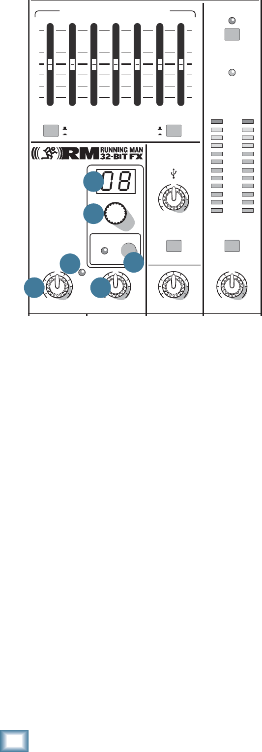
24
ProFX8 and ProFX12
ProFX8 and ProFX12
Stereo Effects Processor
The Mackie Running-Man 32-bit internal effects pro-
cessor is a mono-in, stereo-out effects processor, with
16 presets. It is fed by adjusting the aux FX control [27]
on each channel. The FX master knob [52] adjusts the
overall level entering the FX processor, and the OL LED
[53] shows if the level is too high.
The output from the processor can be added to the
main mix by adjusting the FX return fader [46]. Its
output can also be added to the monitor mix by adjust-
ing the FX to mon [54] knob.
49. PRESET DISPLAY
This display shows the number of the currently
selected effects preset, as shown in the list of presets
silkscreened to the left of the display.
50. PRESET SELECTOR
Rotate this knob to increase or decrease the number
of the preset. It will fl ash in the display [49] until you
press this selector inwards to select the preset.
Scrolling back to the current preset or selecting a new
one will stop the fl ashing.
The available presets are shown in the table on the
next page, and are marked on the panel silkscreen.
(Only one preset can be selected at a time.)
51. INTERNAL FX MUTE and LED
When engaged, the internal effects processor is
muted. Its output will not appear in the main mix or
monitors, and the adjacent LED will come on. The
footswitch connection [16] becomes disabled, and you
will not be able to use the footswitch to mute or unmute
the effects.
If this switch is not engaged, then the internal effects
can be muted or unmuted with your footswitch.
52. FX MASTER
Use this knob to control the level of the signals going
into the internal effects processor. Adjust it carefully,
with your inner magical eye on the adjacent OL LED
[53] to prevent overloading the effects processor.
Fully down is off, 12 o'clock is unity gain, and fully up
is 15 dB of gain.
It also affects the level going out of the FX send out-
put [14].
53. OL LED
This LED illuminates when the effects processor is
being overloaded with too strong a signal (OL). Turn
down the FX master [52] if it is.
The signals going into the processor are affected by
the channel aux FX controls [27], and the channel fad-
ers [31]. Check the LED if you alter these controls.
54. FX TO MON
This knob allows you to add the output of the internal
FX processor to the stage monitor mix. Fully down is off,
12 o'clock is unity gain, and fully up is 15 dB of gain.
8K4K2K1K500250125
15
15
10
10
5
5
0
15
15
10
10
5
5
0
PHONES
STEREO GRAPHIC EQ
U
+15
FX TO MON
FX MASTER
U
+15
OO
OO
PRESETS
FX PRESETS
01 BRIGHT ROOM
02 WARM LOUNGE
03 SMALL STAGE
04 WARM THEATER
05 WARM HALL
06 CONCERT HALL
13 DELAY 1 (300ms)
14 DELAY 2 (380ms)
15 DELAY 3 (480ms)
16 REVERB + DLY (250ms)
07 PLATE REVERB
08 CATHEDRAL
09 CHORUS
10 CHORUS + REV
11 DOUBLER
12 TAPE SLAP
0dB=0dBu
MAIN
METERS
OL
4
6
3
10
15
7
10
20
30
0
2
BREAK
(MUTES ALL CHANNELS)
PHANTOM
POWER
POWER
OO
+20
U
TAPE LEVEL
OO
+20
U
USB THRU
OO
MAX
OL
MAIN MIX
MON
EQ IN
BYPASS
RL
INPUT LEVEL
USB
MUTE
48V
5452
50
49
51
53

25
Owner’s Manual
Owner’s Manual
No. Title Description Example of its use
1 BRIGHT ROOM This room has a bright tone with lots of scattered
refl ections to simulate harder, more refl ective
surfaces.
Useful on vocals that require a brighter re-
verb to cut through the mix, or for giving
acoustic instruments a livelier vibe.
2 WARM LOUNGE This preset features a medium sized room/lounge
sound, with just enough enhancement of the lower
mids to produce a warm tone.
Useful for vocals on songs that require
a larger, more “wet” sound, or for giving
dimension to bright horns without adding
harshness.
3 SMALL STAGE This preset simulates the sound of a small concert
stage, with a medium reverb time and reverberant
space.
Useful for vocals or guitars in fast paced,
high-energy songs that call for a “live”
sounding reverberation.
4 WARM THEATER This reverb has a warm bodied tone and medium
long reverb time to simulate the live acoustics of a
theater space.
Perfect for vocals, drums, acoustic and
electric guitars, keyboards, and more.
5 WARM HALL This reverb simulates the sound of a spacious,
yet cozy, heavily draped and carpeted concert hall
with an especially warm tone.
Perfect for adding natural concert hall
ambience to close-mic’ed orchestral
instruments.
6 CONCERT HALL This hall reverb is characterized by its large, spa-
cious sound, long pre-delay, and vibrant tone. Adds life to acoustic instruments and
vocals from solos to full-on symphonies
and choirs.
7 PLATE REVERB This preset emulates vintage mechanical rever-
beration that was generated with a metal plate.
Its sound is characterized by lots of early refl ec-
tions and no pre-delay.
Perfect for thickening percussive instru-
ments, such as a snare drum, or tight
vocal arrangements.
8 CATHEDRAL This reverb emulates the extremely long tails,
dense diffusion and long pre-delays and refl ec-
tions that would be found in a very large, stone
walled house of worship.
Gives amazing depth to choirs, wind
instruments, organs, and soft acoustic
guitars.
9 CHORUS This preset provides a soft, ethereal sweeping
effect that is useful for thickening and for making
a particular sound pop out of the mix.
Perfect for enhancement of electric and
acoustic guitar and bass, or to add a dra-
matic effect to vocals, particularly group
harmonies and choirs.
10 CHORUS + REV This preset perfectly combines the chorus effect
above with a large, roomy reverb. This lets you both thicken your sound
with the chorus effect while adding
warmth and spaciousness thanks to the
smooth reverb.
11 DOUBLER This effect simulates the sound of a vocal or
instrument being recorded twice (double tracked)
on a multi-track recorder. (50MS)
Provides a vibe that is similar to chorus
without the subtle swirl.
12 TAPE SLAP This effect provides a single, relatively rapid delay
of the original signal, with the added warmth that
vintage tape-based echo units provided. (180 MS)
Often used on vocals for a 1950’s era feel,
or on guitars for a surf-type tone. Often
used by people whose favorite number is
12.
13
14
15
DELAY 1 (300MS)
DELAY 2 (380MS)
DELAY 3 (480 MS)
These delay presets provide around three repeats
of the original signal. The default delay time for
each preset is shown in ms - the smaller the time,
the faster the delay.
These work best with full, up-beat music
like rock where the delay needs to cut
through the mix.
16 REVERB + DLY
(250MS) This effect combines the warm theater reverb ef-
fect with the echoes of the 3-repeat delay effect. Perfect for thickening vocals while adding
dimension, it can also be used as a spacey
effect on electric guitars.
TABLE OF INTERNAL EFFECTS

26
ProFX8 and ProFX12
ProFX8 and ProFX12
Appendix A: Service Information
If you think your ProFX mixer has a problem, please
check out the following troubleshooting tips and do your
best to confi rm the problem. Visit the support section of
our website (www.mackie.com) where you will fi nd lots
of useful information such as FAQs, documentation and
user forums. You may fi nd the answer to the problem
without having to send your mixer away.
Troubleshooting
Bad Channel
• Has the gain been set correctly?
• Is the mute switch on?
• Is the fader turned up?
• Is the channel OL LED on?
• Is the channel EQ set moderately?
• Try unplugging any insert devices.
• Try the same source signal in another channel,
set up exactly like the suspect channel.
Bad Output
• Is the associated level fader (if any) turned up?
• Are any OL LEDS on in the channels, main
meters or internal FX?
• If it’s one of the main outs, try unplugging all
the others. For example, if it’s the 1⁄4" left main
out, unplug the RCA and XLR left outputs. If
the problem goes away, its not the mixer.
• If it’s a stereo pair, try switching them around.
For example, if a left output is presumed dead,
switch the left and right cords, at the mixer
end. If the problem switches sides, it’s not the
mixer.
Noise
• Turn the channel gain and faders down, one
by one. If the sound disappears, it’s either that
channel or whatever is plugged into it, so un-
plug whatever that is. If the noise disappears,
it’s from your whatever.
Power
• Unplug the power cord and check the fuse
located in a fuse tray just below the AC power
connector.
Repair
For warranty repair or replacement, refer to the war-
ranty information on page 35.
Non-warranty repair for Mackie products is available
at a factory-authorized service center. To locate your
nearest service center, visit www.mackie.com, click
“Support” and select “Locate a Service Center.” Service
for Mackie products living outside the United States can
be obtained through local dealers or distributors.
If you do not have access to our website, you can call
our Tech Support department at 1-800-898-3211, Mon-
day-Friday, 7 am to 5 pm Pacifi c Time, to explain the
problem. Tech Support will tell you where the nearest
factory-authorized service center is located in your area.
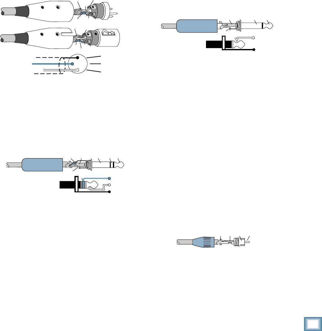
27
Owner’s Manual
Owner’s Manual
“XLR” Connectors
Mackie mixers use 3-pin female “XLR” connectors on
all microphone inputs, with pin 1 wired to the grounded
(earthed) shield, pin 2 wired to the “high” (”hot” or
positive polarity) side of the audio signal and pin 3
wired to the “low” (“cold” or negative polarity) side of
the signal. See Figure A. This is all totally aboveboard
and in full accord with the hallowed standards dictated
by the AES (Audio Engineering Society).
Use a male “XLR”-type connector, usually found on the
nether end of what is called a “mic cable,” to connect to
a female XLR jack.
1⁄4" TRS Phone Plugs and Jacks
“TRS” stands for Tip-Ring-Sleeve, the three
connections available on a “stereo” 1⁄4" or “balanced”
phone jack or plug. See Figure B.
TRS jacks and plugs are used in several different ap-
plications:
• Stereo Headphones, and rarely, stereo micro-
phones and stereo line connections.
When wired for stereo, a 1⁄4" TRS jack or plug
is connected tip to left, ring to right and sleeve
to ground (earth). Mackie mixers do not
directly accept 1-plug-type stereo micro phones.
They must be separated into a left cord and a
right cord, which are plugged into the two mic
preamps.
Appendix B: Connections
• Balanced mono circuits. When wired as a bal-
anced connector, a 1⁄4" TRS jack or plug is con-
nected tip to signal high (hot), ring to signal
low (cold), and sleeve to ground (earth).
• Unbalanced Send/Return circuits. When wired
as send/return “Y” connector, a 1⁄4" TRS jack
or plug is connected tip to signal send (output
from mixer), ring to signal return (input back
into mixer), and sleeve to ground (earth).
1⁄4" TS Phone Plugs and Jacks
“TS” stands for Tip-Sleeve, the two connections avail-
able on a “mono” 1⁄4" phone jack or plug. See Figure C.
TS jacks and plugs are used in many different
applications, always unbalanced. The tip is connected to
the audio signal and the sleeve to ground (earth). Some
examples:
• Unbalanced microphones
• Electric guitars and electronic instruments
• Unbalanced line-level connections
RCA Plugs and Jacks
RCA-type plugs (also known as phono plugs) and
jacks are often used in home stereo and video equip-
ment and in many other applications (Figure D). They
are unbalanced and electrically identical to a 1⁄4" TS
phone plug or jack (see Figure C). Connect the signal to
the center post and the ground (earth) or shield to the
surrounding “basket.”
SLEEVE
TIP
TIPSLEEVE
TIP
SLEEVE
Figure C: TS Plug
2
2
31
1
SHIELD
COLD
HOT
SHIELD
COLD
HOT
3
SHIELD
COLD
HOT
3
2
1
Figure A: XLR Connectors
SLEEVE
TIPSLEEVE
TIP
RING
RING
TIP
SLEEVERING
Figure B: 1⁄4" TRS Plugs
TI
P
SLEEVETIPSLEEVE
Figure D: RCA Plug
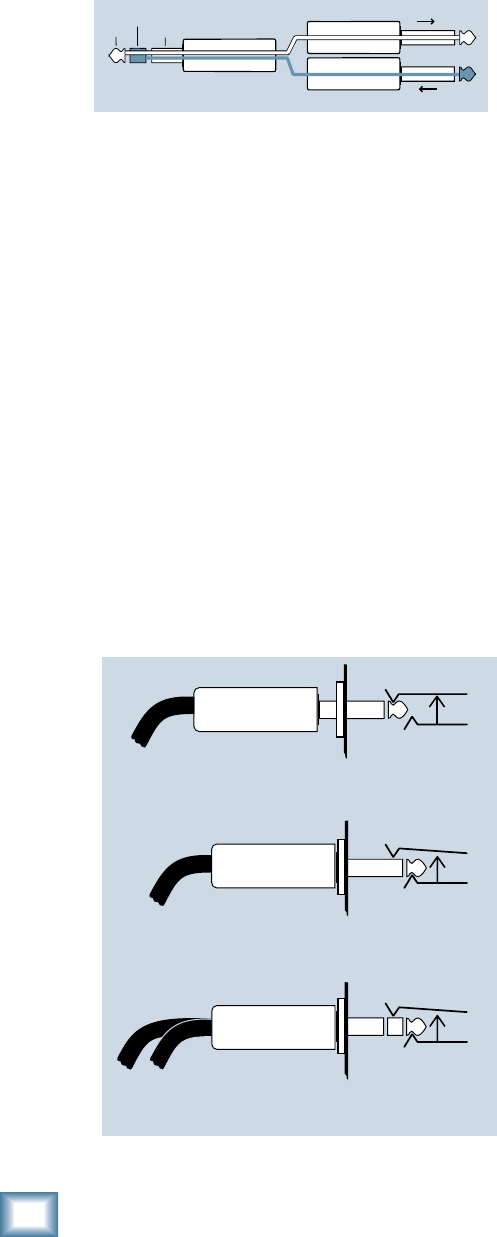
28
ProFX8 and ProFX12
ProFX8 and ProFX12
Mackie Stereo Inputs and Returns: Mono,
Stereo, Whatever
Stereo line inputs and stereo returns are a fi ne
example of the Mackie philosophy (which we just made
up) of Maximum Flexibility with Minimum Headache.
The inputs and returns will automatically be mono or
stereo, depending upon how you use the jacks. Here’s
how it works:
A mono signal should be patched into the input or re-
turn jack labeled left (mono). The signal will be routed
to both the left and right sides of the return circuit, and
will show up in the center of the stereo pair of buses it’s
assigned to, or it can be “panned” with the pan control.
A stereo signal, having two plugs, should be patched
into the left (mono) and the right input or return jacks.
A jack switch in the right jack will disable the mono
function, and the signals will show up in stereo.
A mono signal connected to the right jack will show
up in the right bus only. You probably will only want to
use this sophisticated effect for special occasions.
TRS Send/Receive Insert Jacks
Mackie’s single-jack inserts are the three- conductor,
TRS-type 1⁄4" phone. They are unbalanced, but have
both the mixer output (send) and the mixer input
(return) signals in one connector. See Figure E.
The sleeve is the common ground (earth) for both
signals. The send from the mixer to the external unit is
carried on the tip, and the return from the unit to the
mixer is on the ring.
Using the Send only on an Insert Jack
If you insert a TS (mono) 1⁄4" plug only partially (to
the fi rst click) into a Mackie insert jack, the plug will
not activate the jack switch and will not open the insert
loop in the circuit (thereby allowing the channel signal
to continue on its merry way through the mixer).
This allows you to tap out the channel or bus signal
without interrupting normal operation.
If you push the 1⁄4" TS plug in to the second click, you
will open the jack switch and create a direct out, which
does interrupt the signal in that channel. See Figure F.
NOTE: Do not overload or short-circuit the signal you
are tapping from the mixer. That will affect the internal
signal.
“tip”
This plug connects to one of the
mixer’s Channel Insert jacks. “ring”
tip ring sleeve
SEND to processor
RETURN from processor
(TRS plug)
Figure E
Direct out with no signal interruption to master.
Insert only to first “click.”
Channel Insert jack
Channel Insert jack
Channel Insert jack
Direct out with signal interruption to master.
Insert all the way in to the second “click.”
For use as an effects loop.
(TIP = SEND to effect, RING = RETURN from effect.)
MONO PLUG
MONO PLUG
STEREO
PLUG
Figure F

29
Owner’s Manual
Owner’s Manual
Appendix C: Technical Information
Specifi cations
Noise
20 Hz – 20 kHz, 150 Ohm Source Impedance
Equivalent Input Noise
(Mic in to Insert Send out, max gain) -127 dBu
Residual Output Noise
(All outputs, master levels off, all channel levels off)
-95 dBu
(All outputs, master levels unity, all channel levels off)
-90 dBu
(All outputs, master levels unity, one channel level unity)
-85 dBu
Distortion
20 Hz – 20 kHz
THD+N, SMPTE IMD
(Mic input to Main output) <0.05% @ +4 dBu output
Common Mode Rejection Ratio
1 kHz
(Mic input to Insert Send output) 60 dB gain at unity
Frequency Response
20 Hz – 30 kHz
(Mic input to any output, gain at unity) +0 dB/-1 dB
Crosstalk
20 Hz – 20 kHz
Adjacent Inputs -90 dB @ 1 kHz
Inputs to Outputs -90 dB @ 1 kHz
Fader Off -90 dB @ 1 kHz
Mute Switch/Break Switch Mute -90 dB @ 1 kHz
Maximum Levels
All Inputs +22 dBu
Main Mix XLR +28 dBu
All other outputs +22 dBu
Impedances
Mic in 3 kilohms
Channel Insert return 10 kilohms
Ch 1 Instrument Input 1 Megaohm
All other inputs 20 kilohms
Tape out 1.1 kilohms
Phones out 25 ohms
All other outputs 120 ohms
Maximum Voltage Gain (EQ Flat)
Mic Input Channel to
Insert Output 50 dB
Tape Output 60 dB
USB Output 60 dB
¼ Inch Main Output 70 dB
XLR Main Output 76 dB
Monitor Send 75 dB
FX Send 90 dB
Mono Line Input Channel to
Insert Output 30 dB
Tape Output 40 dB
USB Output 40 dB
XLR Main Output 56 dB
Monitor Send 55 dB
FX Send 70 dB
Stereo Line Input Channel to
Tape Output 30 dB
USB Output 30 dB
XLR Main Output 46 dB
Monitor Send 45 dB
FX Send 60 dB
Tape Input to
Tape Output 20 dB
USB Output 20 dB
XLR Main Output 36 dB
USB Input to
Tape Output 20 dB
USB Output 20 dB
XLR Main Output 36 dB
Stereo Return to
Tape Output 10 dB
USB Output 10 dB
XLR Main Output 26 dB
Effects Return to
Tape Output 10 dB
USB Output 10 dB
XLR Main Output 26 dB
Monitor Send 25 dB
Channel EQ
Low Cut 100 Hz, -18 dB/Octave
High Shelving ±15 dB @ 12 kHz
Mid Peaking ±15 dB @ 2.5 kHz
Low Shelving ±15 dB @ 80 Hz
Digital Effects
I/O Mono Input/Stereo Output
Number of Presets 16 Mackie-designed presets
Channel Level Set LED
0 dBu (normal operating level)
Channel OL LED
-1 dB before channel clipping
Measured post EQ, pre fader
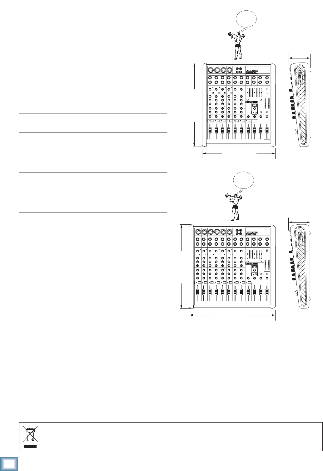
30
ProFX8 and ProFX12
ProFX8 and ProFX12
Dimensions
Meters
Main L/R Mix
Two columns of 12 segments each:
OL (+20 dBu), +15, +10, +6, +3, 0 (0 dBu), -2, -4, -7, -10, -20,
and -30
7 Band Graphic EQ
Frequency Centers 125, 250, 500, 1k, 2k, 4k, 8k
Gain ±15 dB
Assignable to Main or Monitor
Bypassable
USB
Format USB 1.1
I/O Stereo Input/Stereo Output
A/D/A 16 Bit, 44.1 kHz/48 kHz
Phantom Power
48 VDC to all Mic channels at once
AC Power Requirements
Voltage Range 100-240 VAC, 50-60 Hz
Power Consumption: 20 Watts (ProFX8)
25 Watts (ProFX12)
Power Connector 3 Pin IEC
Dimensions (H x W x D)
ProFX8 14.05" x 11.41" x 3.58"
(357 mm x 290 mm x 91 mm)
ProFX12 14.05" x 14.6" x 3.58"
(357 mm x 370 mm x 91 mm)
Weight
ProFX8 7.1 lb (3.2 kg)
ProFX12 9.0 lb (4.1 kg)
LOUD Technologies Inc. is always striving to improve our prod-
ucts by incorporating new and improved materials, components,
and manufacturing methods. Therefore, we reserve the right to
change these specifi cations at any time without notice.
“Mackie,” and the “Running Man” are registered trademarks of
LOUD Technologies Inc. All other brand names mentioned are
trademarks or registered trademarks of their respective hold-
ers, and are hereby acknowledged.
©2008 LOUD Technologies Inc. All Rights Reserved.
Correct disposal of this product. This symbol indicates that this product should not be disposed of with your household waste, according to the WEEE Directive (2002/96/EC) and your national law. This product
should be handed over to an authorized collection site for recycling waste electrical and electronic equipment (EEE). Improper handling of this type of waste could have a possible negative impact on the environment and
human health due to potentially hazardous substances that are generally associated with EEE. At the same time, your cooperation in the correct disposal of this product will contribute to the effective usage of natural
resources. For more information about where you can drop off your waste equipment for recycling, please contact your local city offi ce, waste authority, or your household waste disposal service.
14.05 in/ 357mm
WEIGHT
9.0 lb
4.1 kg
WEIGHT
7.1 lb
3.2 kg
14.6 in/ 370 mm
3.58 in/
91 mm
14.05 in/ 357mm
11.41 in/ 290 mm
3.58 in/
91 mm
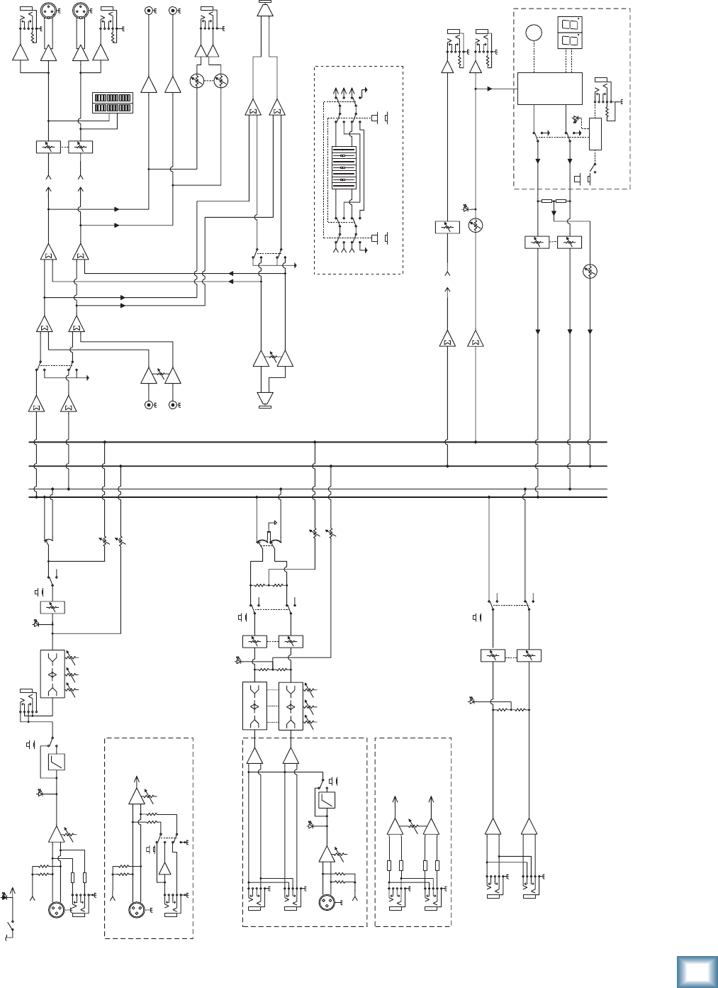
31
Owner’s Manual
Owner’s Manual
Block Diagram
L
RMain
Phones
Level
Main Fader
Insert
HPF Fader
Pan Left
Right
FX level
Phones
L sum
R sum
Mon (pre)Mon (pre)
3-Band EQ
FX (post)FX (post)
Internal FX
L
R
Stereo Return
L
R
Main
Fader
100 Hz
NOTE: Switches are shown in the default (out) position.
Mute
Main out
48V
Mono
Channels
2-2 ProFX8
2-4 ProFX12
Mic +
-
Mic: 0 ~ +50dB
Line: -20 ~ +30dB
Hybrid
Channels
3-6 ProFX8
5-8 ProFX12
L
R
3-Band EQ Fader
Pan
to/from
7-Band
GEQ
Line
Gain
OL (Flicker)
Monitor send
Mon Fader
Preset select
FX
Preset
Display
footswitch
FX Mute
active
FX to Main L/R Fader
OL
Global 48v
Switch/LED
to/from
7-Band EQ
Tape Out
Left
FX
Mon
FX
Mon
Low Cut In
Mic
L
R
Gain
HPF
100 Hz
+
-
Mic Gain:
0 ~ +50dB
Stereo
Channels
7-8 ProFX8
9-12 ProFX12
USB
Out
FX send
FX Bypass
Logic
In
FX
Out L
Out R
FX to Mon
LO
80 2.5K 12K
HIMID
LO
80 2.5K 12K
HIMID
Phantom Power
(To All Mics)
Phantom Power
Phantom
Power
Mute
Mute
OL (Flicker)
LO
80 2.5K 12K
HIMID
Line Gain:
-20 ~ +20 dB
OL (Flicker)
Break
switch
Low Cut In
Level Set
Level Set Level
USB Thru
Bypass
switch
7-band Stereo
GEQ Bypass
EQ In
EQ assign
switch
Mon
Mains
Main R
Main L
Mon
Main R
Main L
Mon
Note: When not assigned to EQ, signal is sent to straight through to destination.
Right
Main
Meters
USB Input
Tape Input
L
R
Level
L
R
Mono
Channel
1 ProFX8
1 ProFX12
Mic +
-
Mic: 0 ~ +50dB
Line: -20 ~ +30dB
Line /
Hi-Z
Gain
Phantom
Power
Line /
Hi-Z
32
ProFX8 and ProFX12
ProFX8 and ProFX12
Appendix D: USB interface
System Requirements
These are the minimum requirements for your com-
puter system to use the mixer's USB interface.
For the PC:
• Windows XP (service pack 2)
• Pentium 4 or Athlon XP processor
• 256 MB RAM
For the Mac:
• OS X (10.4.11 or higher)
• G4 processor
• 256 MB RAM
The internal USB interface will allow the left and
right main mix to be recorded on a Mac or PC computer.
It also allows two channels of audio from the computer
to be added to the main mix.
Plug and Play
No drivers or software installation is required. The
ProFX mixer's USB interface connects directly to the
USB port of your computer.
USB stream from computer
The following table shows the outputs from your com-
puter to the mixer’s USB interface:
The 2-channel digital stream from the computer
enters the mixer through the USB connector and is
converted to analog audio.
The audio level can be adjusted using the USB input
control [40].
Beware of a possible feedback loop, if you are
feeding the main mix back into the mixer.
USB stream to computer
In addition to a mix of channels, the USB output to
your computer can contain audio from your computer, if
the USB thru switch [41] is engaged.
The mains and headphone outputs are not af-
fected by the switch, and always provide a full
mix of channels and any 2-channel audio from
your computer.
The analog audio from the mixer is converted to digi-
tal signals by the USB interface’s A/D converters.
The following table shows the outputs to your com-
puter from the mixer’s USB interface:
Here are two examples of using the USB thru switch:
Studio Overdub – Tracktion playback is coming into
the mixer on USB inputs, and routing through
the mains/phones for you to hear. A guitar
plugged into channel 1 is being recorded via the
USB output, while you listen and play along to
the Tracktion playback. The USB thru switch is
out, so the output to be recorded on the com-
puter contains all playing channels except the
playback from the computer.
Live Performance – Computer playback software
like Ableton Live is being mixed to the mains
with other stereo sources such as synths, sam-
plers, turntables, and CD-DJ players. The USB
thru switch is engaged, so everything will be
fed to the computer for recording the entire set
with Ableton Live.
To From
Computer input 1 Left mix of channels including
any audio from computer
(thru switch in)
or
Left mix of channels without
audio from computer
(thru switch out)
Computer input 2 Right mix of channels including
any audio from computer
(thru switch in)
or
Right mix of channels without
audio from computer
(thru switch out)
From To
Computer output 1 Main mix L
Computer output 2 Main mix R

33
Owner’s Manual
Owner’s Manual
Monitoring
When recording to computer software with a ProFX
mixer, use direct hardware monitoring:
• Listen to the track you are recording directly off
of your mixer, while also listening to previously-
recorded tracks on your DAW software, as they
are fed back into the mixer.
The procedure is as follows:
• Arm the track you wish to record onto, on your
DAW software, such as Tracktion.
• On the track you have just armed, disable input
monitoring (see top of next page), so that
while recording, you do not hear the return
of that track coming from the computer. This
will ensure you do not mix the direct track you
are monitoring, with the duplicate of the track
on the DAW as it is being recorded. You do not
want to hear the direct and DAW track of the
same source simultaneously, as the DAW ver-
sion might be slightly delayed, and the combi-
nation of the two will produce a fi ltered sound.
• Make sure that the DAW’s input meters show
a healthy level, and if it needs to be increased
or decreased, adjust the signal’s channel fader
[31], not the gain knob [20].
• Press record on the DAW and record the track.
Overdubbing
To overdub additional tracks while listening to previ-
ously recorded ones, follow these steps:
• Press Play. The previously recorded track will
now play out of the DAW’s main L-R mix into
the USB input of the mixer.
• Set the level of the USB input level knob [40]
to a level where you can hear the previously
recorded track comfortably.
• Arm a new track in the DAW software, be sure it
has input monitoring disabled (see top of next
page), and record the new track on your DAW.
• While recording the new track, you will hear
the previously recorded tracks coming into
the mixer’s USB input, while you simultane-
ously hear the current track you are recording
directly through the mixer hardware.
• Repeat these steps until you have built up all
the tracks of your recording.
The mixer's built-in USB connection allows overdub
style recording to a Mac or PC digital audio workstation
(DAW) through the USB cable.
Here are some steps showing how to record a fi rst
track, and then record additional tracks while monitor-
ing ones that have already been recorded.
1. Connect to the mixer, the sound source you
wish to record to your audio software, for ex-
ample:
• A microphone for a voice or instrument.
• A line-level source such as an electronic
keyboard.
• An instrument connected directly to the
instrument input 1 (with the hi-z switch
[7] pressed in).
2. Make sure the USB thru switch [41] is not
pressed in. This will ensure that during each
recording pass, the audio software only receives
the track-in-progress as an audio signal, and
not the pre-existing mix from the computer as
well.
3. Set the gain knob [20] at the top of the channel
you are using, to an appropriate level for the
source being recorded, using the level set LED
[21] as a guide. Once the gain has been set, set
the channel fader [31] to unity (U).
The signals going out to your computer are not
affected by the main fader [48] or the head-
phones knob [42].
4. If you are recording an acoustic source through
a microphone, monitor it through headphones,
not through speakers. This will prevent sound
from the speakers from leaking into the micro-
phone. If working in this fashion, turn down
the main fader, and instead turn up the phones
knob for safe listening levels in the head-
phones.
Recording with USB
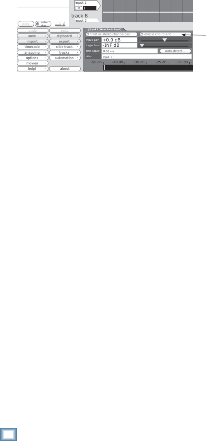
34
ProFX8 and ProFX12
ProFX8 and ProFX12
In Tracktion, to disable input monitoring for the track
you are recording onto, select the input to the track (it
will be highlighted in red) and disable the end-to-end
function.
You’ll hear existing tracks playing back via the USB
in, and you’ll be monitoring the track you are recording
through the mixer’s headphones or main out. When you
play back the recording, you’ll hear the track you’ve just
overdubbed without unmuting anything.
Other DAWs may show this as a speaker next to the
track record arm button.
Other tips
• If recording with a microphone, turn down the
main fader [48] while recording, and listen
through the headphones instead.
• If recording “direct” sources such as an electric
guitar, you can listen with speakers, as there
is no microphone present to worry about the
speaker’s sound leaking in.
A word about latency
Latency describes the amount of time it takes the
input signal to pass through the system, and reach
the output. When recording a guitar and monitoring
through software, it is the amount of time it takes from
the moment you strike your guitar string, to the mo-
ment you hear it in your headphones. You are used to
this latency being very close to zero; when you play your
guitar through a guitar amp, you hear the signal imme-
diately. So when you are recording and monitoring via
software, you want this latency (delay time) to be as low
as possible.
We would like to set the latency as low as possible, but
the smaller it is, the harder the computer will have to
work. If the latency is very small, the computer needs to
work very hard to quickly transfer the audio in and out.
It may not even be able to keep up, especially if there
are lots of tracks, lots of automation and/or lots of plug-
ins in your work. If this happens, your audio may stop or
“drop out.” Drop outs may also occur if you have a slower
computer or not enough memory.
When recording using the overdub method, it is
important to set the mixer’s latency to it’s lowest oper-
able setting. This means going into the audio interface
property page of your recording program and setting the
latency property to the lowest setting the device and
your system will accept without any drop-outs, distor-
tion or CPU overburdening.
The buffer is an area of computer memory that your
DAW uses to hold audio as it works. The smaller the
buffer, the faster audio gets in and out of your com-
puter, and the lower the latency. The size of the buffer
is measured in samples. The more samples, the higher
the latency time value. This time value varies by sample
rate.
Higher latency settings are fi ne and even necessary
when in live record mode. The same is true for mix-
down mode, especially when you start adding lots of
plug-ins.
The latency will never be zero, but generally we can
lower it enough so its effect cannot be heard.
end-to-end disabled
Tracktion Screen

35
Owner’s Manual
Owner’s Manual
ProFX8 and ProFX12 Limited Warranty
A. LOUD Technologies Inc. warrants all materials,
workmanship and proper operation of this product for a period
of one year from the original date of purchase. You may
purchase an additional 24-month Extended Warranty (for a
total of 36 months of coverage). Visit our website and follow
the “Product Registration” links for details (www.mackie.com).
If any defects are found in the materials or workmanship or
if the product fails to function properly during the applicable
warranty period, LOUD Technologies, at its option, will repair
or replace the product. This warranty applies only to
equipment sold and delivered within the U.S. and
Canada by LOUD Technologies Inc. or its authorized
dealers.
B. For faster processing, register online at www.mackie.com,
or you may mail in the product registration card included with
this manual.
C. Unauthorized service, repairs, or modifi cation of Mackie
products will void this warranty. To obtain repairs or
replacement under warranty, you must have a copy of your
sales receipt from the authorized Mackie dealer where you
purchased the product. It is necessary to establish purchase
date and determine whether your Mackie product is within
the warranty period.
D. To obtain warranty repair or replacement:
1. Call Mackie Technical Support at 800/898-3211, 7
AM to 5 PM Monday through Friday (Pacifi c Time) to get
authorization for repair or replacement. Alternately, go
to the Mackie website, click “Support” (www.mackie.
com/support), and follow the instructions for reporting
a warranty issue and submitting a request for an advance
replacement.
2. Advance Replacement: Mackie will ship a
replacement unit to you along with an invoice for the
suggested retail price of the replacement unit. You must
return the defective unit immediately to cancel the invoice.
If you do not return the defective unit within 30 days, you
must pay the full amount stated in the invoice to satisfy
your debt.
3. Repair: When you call Mackie Technical Support,
explain the problem and obtain a Service Request Number.
Have your Mackie product’s serial number ready. You must
have a Service Request Number before you can obtain
factory-authorized service.
• Pack the product in its original shipping carton. Also
include a note explaining exactly how to duplicate the
problem, a copy of the sales receipt with price and date
showing, your daytime phone number and return street
address (no P.O. boxes or route numbers, please!), and
the Service Request Number. If we cannot duplicate the
problem or establish the starting date of your Limited
Warranty, we may, at our option, charge for service time
and parts.
• Ship the product in its original shipping carton, freight
prepaid to the authorized service center. Write the Service
Request Number in BIG PRINT on top of the box. The
address of your closest authorized service center will be
given to you by Technical Support, or it may be obtained
from our website. Once it’s repaired, the authorized service
center will ship it back by ground shipping, pre-paid (if it
qualifi ed as a warranty repair).
Note: Under the terms of the warranty, you must ship or drop-
off the unit to an authorized service center. The return ground
shipment is covered for those units deemed by us to be under
warranty.
Note: You must have a sales receipt from an authorized
Mackie dealer for your unit to be considered for warranty
repair.
IMPORTANT: Make sure that the Service Request
Number is plainly written on the shipping carton.
No receipt, no warranty service.
E. LOUD Technologies reserves the right to inspect
any products that may be the subject of any warranty
claims before repair or replacement is carried out. LOUD
Technologies may, at our option, require proof of the original
date of purchase in the form of a dated copy of the original
dealer’s invoice or sales receipt. Final determination of
warranty coverage lies solely with LOUD Technologies.
F. Any products returned to one of the LOUD Technologies
factory-authorized service centers, and deemed eligible
for repair or replacement under the terms of this warranty
will be repaired or replaced. LOUD Technologies and its
authorized service centers may use refurbished parts for
repair or replacement of any product. Products returned
to LOUD Technologies that do not meet the terms of this
Warranty will not be repaired unless payment is received
for labor, materials, return freight, and insurance. Products
repaired under warranty will be returned freight prepaid by
LOUD Technologies to any location within the boundaries of
the USA or Canada.
G. LOUD Technologies warrants all repairs performed
for 90 days or for the remainder of the warranty period.
This warranty does not extend to damage resulting from
improper installation, misuse, neglect or abuse, or to
exterior appearance. This warranty is recognized only if
the inspection seals and serial number on the unit have not
been defaced or removed.
H. LOUD Technologies assumes no responsibility for the
timeliness of repairs performed by an authorized service
center.
I. This warranty is extended to the original purchaser.
This warranty may be transferred to anyone who may
subsequently purchase this product within the applicable
warranty period for a nominal fee (extended warranties
are not transferable). A copy of the original sales receipt is
required to obtain warranty repairs or replacement.
J. This is your sole warranty. LOUD Technologies does
not authorize any third party, including any dealer or
sales representative, to assume any liability on behalf of
LOUD Technologies or to make any warranty for LOUD
Technologies Inc.
K. THE WARRANTY GIVEN ON THIS PAGE IS THE SOLE
WARRANTY GIVEN BY LOUD TECHNOLOGIES INC.
AND IS IN LIEU OF ALL OTHER WARRANTIES, EXPRESS
AND IMPLIED, INCLUDING THE WARRANTIES OF
MERCHANTABILITY AND FITNESS FOR A PARTICULAR
PURPOSE. THE WARRANTY GIVEN ON THIS PAGE SHALL
BE STRICTLY LIMITED IN DURATION TO ONE YEAR
FROM THE DATE OF ORIGINAL PURCHASE FROM AN
AUTHORIZED MACKIE DEALER. UPON EXPIRATION
OF THE APPLICABLE WARRANTY PERIOD, LOUD
TECHNOLOGIES INC. SHALL HAVE NO FURTHER
WARRANTY OBLIGATION OF ANY KIND. LOUD
TECHNOLOGIES INC. SHALL NOT BE LIABLE FOR ANY
INCIDENTAL, SPECIAL, OR CONSEQUENTIAL DAMAGES
THAT MAY RESULT FROM ANY DEFECT IN THE MACKIE
PRODUCT OR ANY WARRANTY CLAIM. Some states do
not allow exclusion or limitation of incidental, special,
or consequential damages or a limitation on how long
warranties last, so some of the above limitations and
exclusions may not apply to you. This warranty provides
specifi c legal rights and you may have other rights which
vary from state to state.
Please keep your sales receipt in a safe place.

16220 Wood-Red Road NE • Woodinville, WA 98072 • USA
United States and Canada: 800.898.3211
Europe, Asia, Central and South America: 425.487.4333
Middle East and Africa: 31.20.654.4000
Fax: 425.487.4337 • www.mackie.com
E-mail: sales@mackie.com
