Maestro Wireless Solutions E228-7 4G WIFI Router User Manual
Maestro Wireless Solutions Limited 4G WIFI Router
User manual
E220 Series
Quick Start Guide
V
3

E220 Series| QUICK START GUIDE http://support.maestro-wireless.com
Page | 2
Table of Contents
1.0
Terms and Conditions ...........................................................................................3
2.0
E220 Series: ...............................................................................................................4
3.0
Setup: ............................................................................................................................5
3.1 Prerequisite ....................................................................................................................... 5
3.2 Available Accessories ................................................................................................... 6
4.0
Maestro Router Overview ...................................................................................7
4.1 LAN Panel Details ............................................................................................................ 7
4.2 WAN Panel Details .......................................................................................................... 9
4.3 Front Panel Details ....................................................................................................... 10
5.0
Connecting Maestro Router .............................................................................11
6.0
Software Configuration......................................................................................14
7.0
Conformity ................................................................................................................17
7.1 Federal Communications Commission (FCC) Compliance Statement 17
7.2 FCC RF Exposure statement ..................................................................................... 17
7.3 ISED Notice ...................................................................................................................... 17
7.4 ISED RF Exposure Information.............................................................................. 18
8.0
Appendix: ....................................................................................................................0
8.1 Pin Power Cable Schematic ....................................................................................... 0
8.2 Power over Ethernet ..................................................................................................... 1
8.3 RS485 wiring diagram .................................................................................................. 2
8.4 Certified antenna ............................................................................................................ 3
8.5 Selection of antenna...................................................................................................... 3

E220 Series| QUICK START GUIDE http://support.maestro-wireless.com
Page | 3
1.0 Terms and Conditions
1.1.1 This manual is written without warranty.
1.1.2 Maestro Wireless Solutions Ltd. reserves the right to modify or improve the product and
its accessories, which can also be withdrawn without prior notice.
1.1.3 The company stresses the fact that the performance of the product and its accessories
depend on the proper use conditions as well as the surrounding environment.
1.1.4 Maestro Wireless Solutions Ltd. assumes no liability for damage incurred directly or
indirectly from errors, omissions or discrepancies between the router and this manual.
1.1.5 Every effort is made to keep the product and its software up to date and running smoothly.
However, Maestro Wireless Solutions Ltd. takes no responsibility for, and will not be liable for
the product or its software being temporarily unavailable due to technical issues beyond our
control.
1.1.6 The above terms and conditions are subject to change without prior notice. The present
use of this product implies that the user approves and understands all the above terms and
conditions.
E220 Series| QUICK START GUIDE http://support.maestro-wireless.com
Page | 4
2.0 E220 Series:
Table 1: E220 Series compatible models
Product
name Territories / Operators Bands
Fall-
back
mode
Bands Cellular Type
E224 EMEA 3/8/20 2G 3/8 LTE cat. 1
E224 AT&T, T-Mobile 2/4/12 None N/A LTE cat. 1
E225 Lite
EMEA. Asia 1/8 2G 3/8 3G [1]
E225 Lite
World 1/2/5/6/8/19
2G 2/3/5/8 3G [1]
E225 EMEA, Asia 1/8 2G 3/8 3G [1]
E225 Worldwide 1/2/5/6/8/19
2G 2/3/5/8 3G [1]
E228 Verizon Wireless 4/13 None N/A LTE cat. 4
E228 AT&T, Rogers 2/4/5/13/17
3G [2]
2/5 LTE cat. 4
E228 Telstra, Spark 3/7/28 None N/A LTE cat. 4
E228 NTT Docomo 1/19/21 None N/A LTE cat. 4
E228 Korea, Thailand, Brazil, etc.
1/3/5/7 None N/A LTE cat. 4
[1] 7.2Mbps downlink; 5.76Mbps uplink; [2] 43.2Mbps downlink; 5.76Mbps uplink
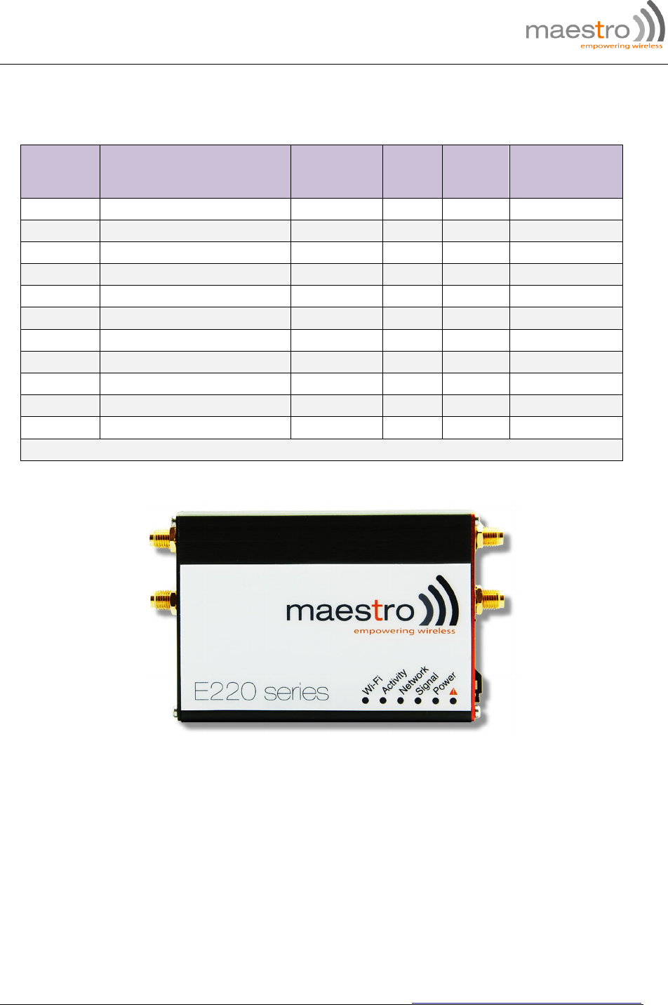
Figure 1: E220 Series: High-speed 3G or LTE router

E220 Series| QUICK START GUIDE http://support.maestro-wireless.com
Page | 5
3.0 Setup:
3.1 Prerequisite
3.1.1 Before installing your E220 Series router, verify you have the following:
Router Hardware with:
o Active sim card
o Ethernet cable
o Wi-Fi and cellular antennas
Computer equipped with:
o Windows, Mac or Linux operating system.
o Ethernet port or Wi-Fi connectivity and Internet service
o Web browser such as Internet Explorer 8+ or Google Chrome, Mozilla Firefox or
Safari to access the Maestro Web Admin Console
o DHCP set to enable.
3.1.2 To enable DHCP, do the following:
From the Start menu, select Control Panel > Network and Sharing Center and
then select the existing connection.
The Network Connection Status dialog box appears. Click Properties > double
click Internet Protocol Version 4 (TCP/IPv4).
The Internet Protocol Version 4 (TCP/IPv4) Properties dialog box appears. Under
the tab General, select Obtain an IP address automatically and Obtain DNS
server address automatically.
E220 Series| QUICK START GUIDE http://support.maestro-wireless.com
Page | 6
3.2 Available Accessories
Table 2: The following accessories are available for purchase:
Item Description
Power Supply / Cable
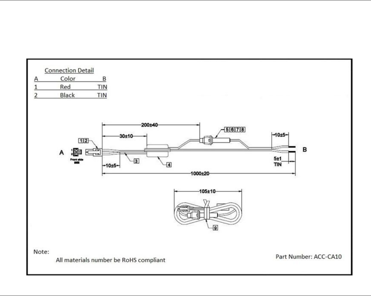
ACC-CA30 2-pin Micro-Fit 3.0 (M) to stripped wire with 2.5 A fused, 1-metre long cable
ACC-PS20 2-pin Molex 1.2A power adapter with Euro plug 2-pin - Europe
ACC-PS21 2-pin Molex 1.2A power adapter with NEMA 2-pin plug - America
ACC-PS22 2-pin Molex 1.2A power adapter with AS3112 3-pin plug – Australia / NZ
ACC-PS23 2-pin Molex 1.2A power adapter with BS1363 3-pin plug - UK
Wi-Fi Antenna
ACC-A21 5-band 2.4 / 5.8GHz dipole antenna, hinged RP-SMA (M)
Cellular / GPS Antenna
ACC-A11 or ACC-A17A
5-band 850 / 900 / 1800 / 1900 / 2100MHz magnetic mount antenna, 3-meter
cable, SMA (M)
ACC-A03 GPS 1575.42MHz Magnetic mount antenna, 3-meter cable, SMA (M)
ACC-A22 Ultra-wide-band 698-960 / 1575.42 / 1710-2700MHz L-shaped antenna,
hinged, SMA (M)
Miscellaneous
ACC-DIN Metal DIN Rail clip
ACC-CA29 RJ45(M) to RJ45(M)-cable length=1000mm
3.2.1 For a full list of Maestro Wireless accessories, refer to: http://www.maestro-
wireless.com/accessories/
E220 Series| QUICK START GUIDE http://support.maestro-wireless.com
Page | 7
4.0 Maestro Router Overview
4.1 LAN Panel Details
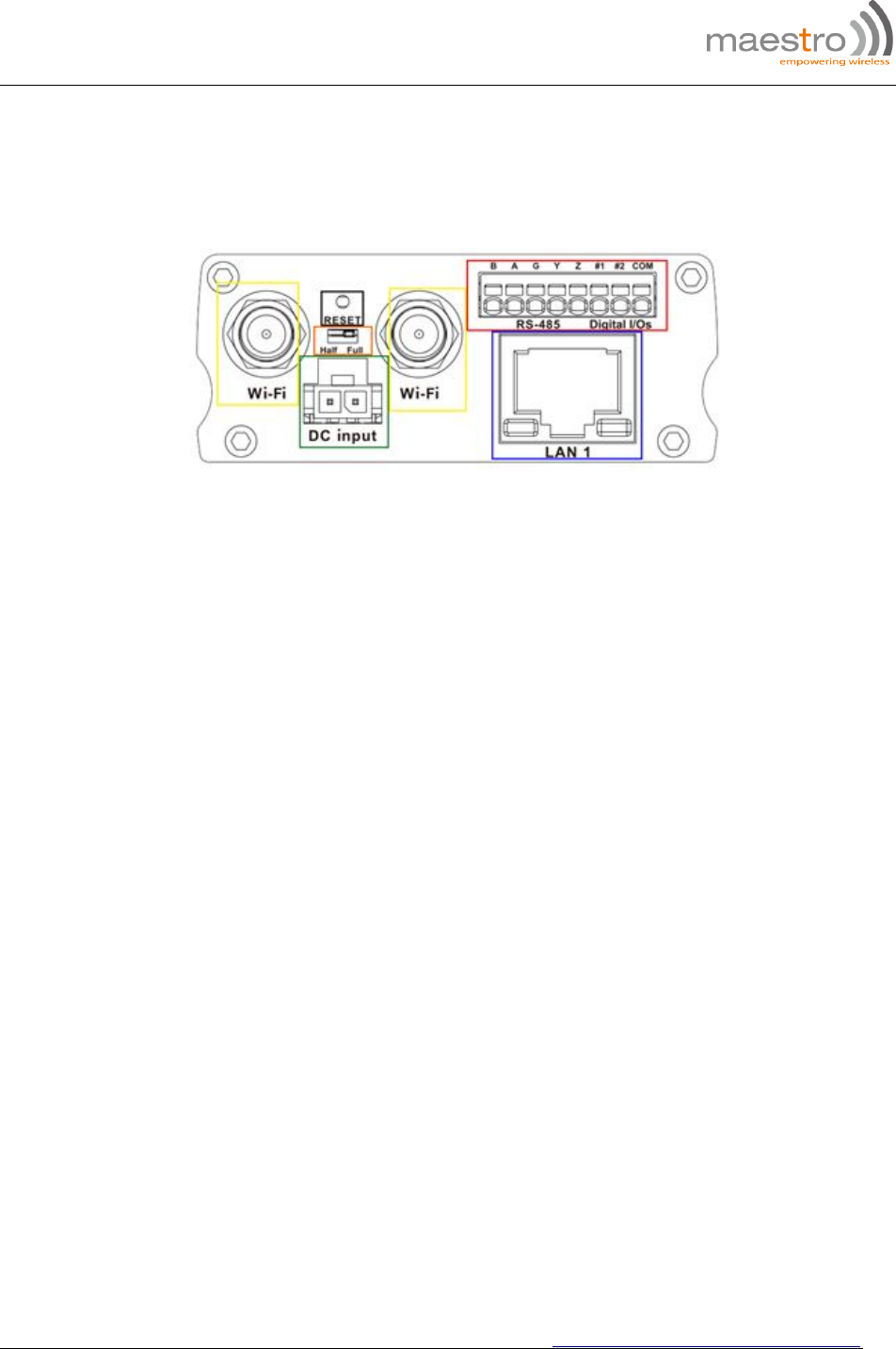
Figure 2: Maestro Router LAN Panel
Yellow - Wi-Fi Connector: RP-SMA antenna connector
Orange - Reset Button: When pushed for 3 seconds the device will reset to default settings.
Green - DC Power Supply: 2-pin Micro-fit 3.0 connector. Black (left) negative red (right)
positive.
Blue - Ethernet port (LAN): Ethernet cable connects to LAN
Red - RS-485 & Digital input/output ports (see figure 3 next page):
E220 Series| QUICK START GUIDE http://support.maestro-wireless.com
Page | 8
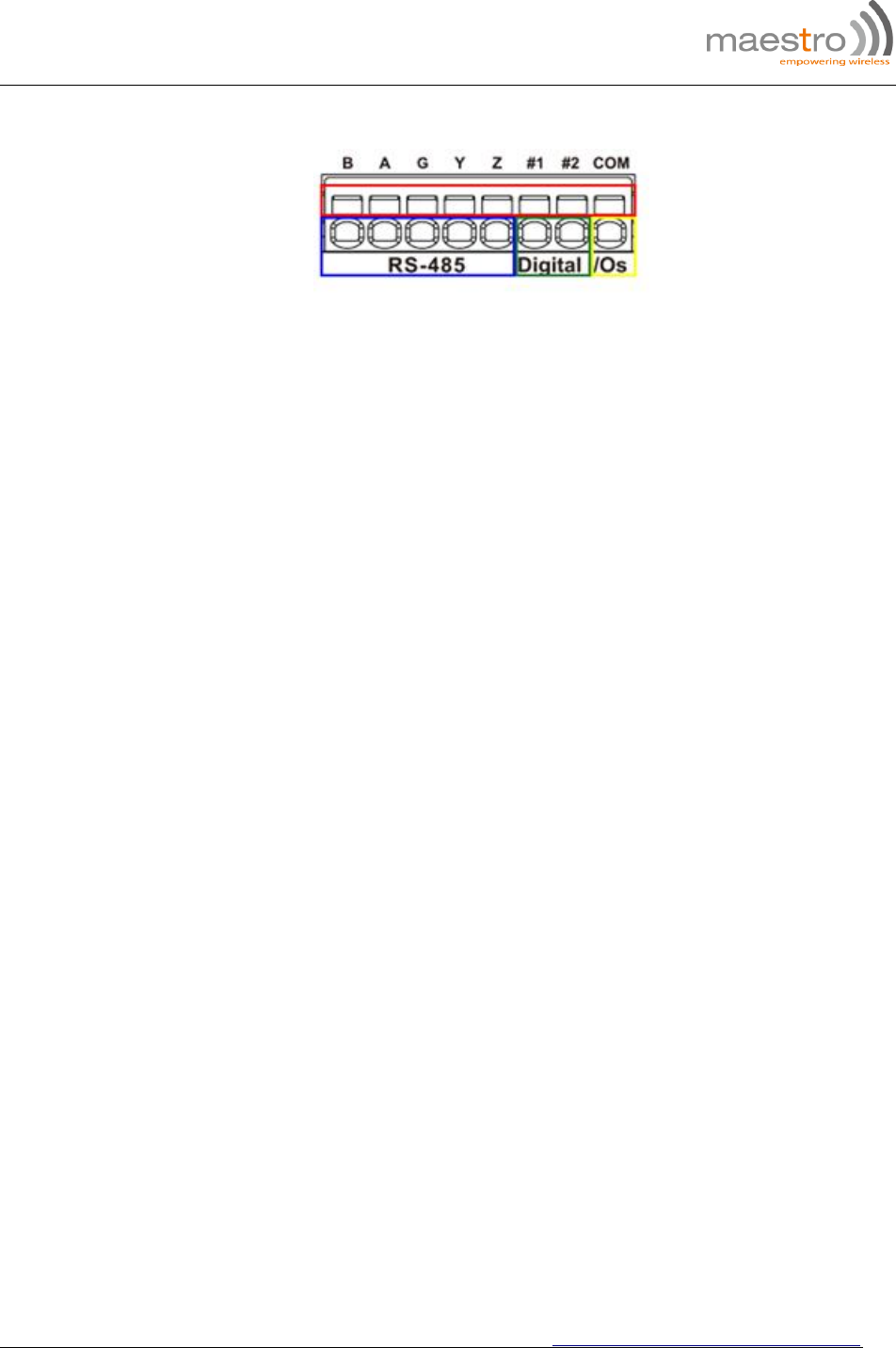
Figure 3: Maestro Router LAN Panel I/O connector
Red - Top slots are release pins for bottom ports.
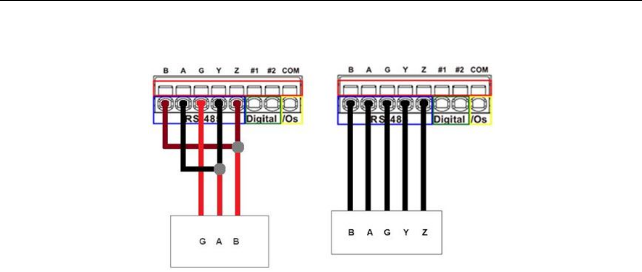
Blue - RS-485
o Full-duplex:
B: Rx –
A: Rx +
G: Common Ground
Y: Tx +
Z: Tx –
o Half-duplex
A&Y: DATA +
B&Z: DATA –
G: Common Ground
Green - DIO Ports configurable as input or output, 20 AWG (recommended).
o Input detection: 5V, max. 48V
o Output: Open collector, max. current 200mA
Yellow - Ground for both DIOs
E220 Series| QUICK START GUIDE http://support.maestro-wireless.com
Page | 9
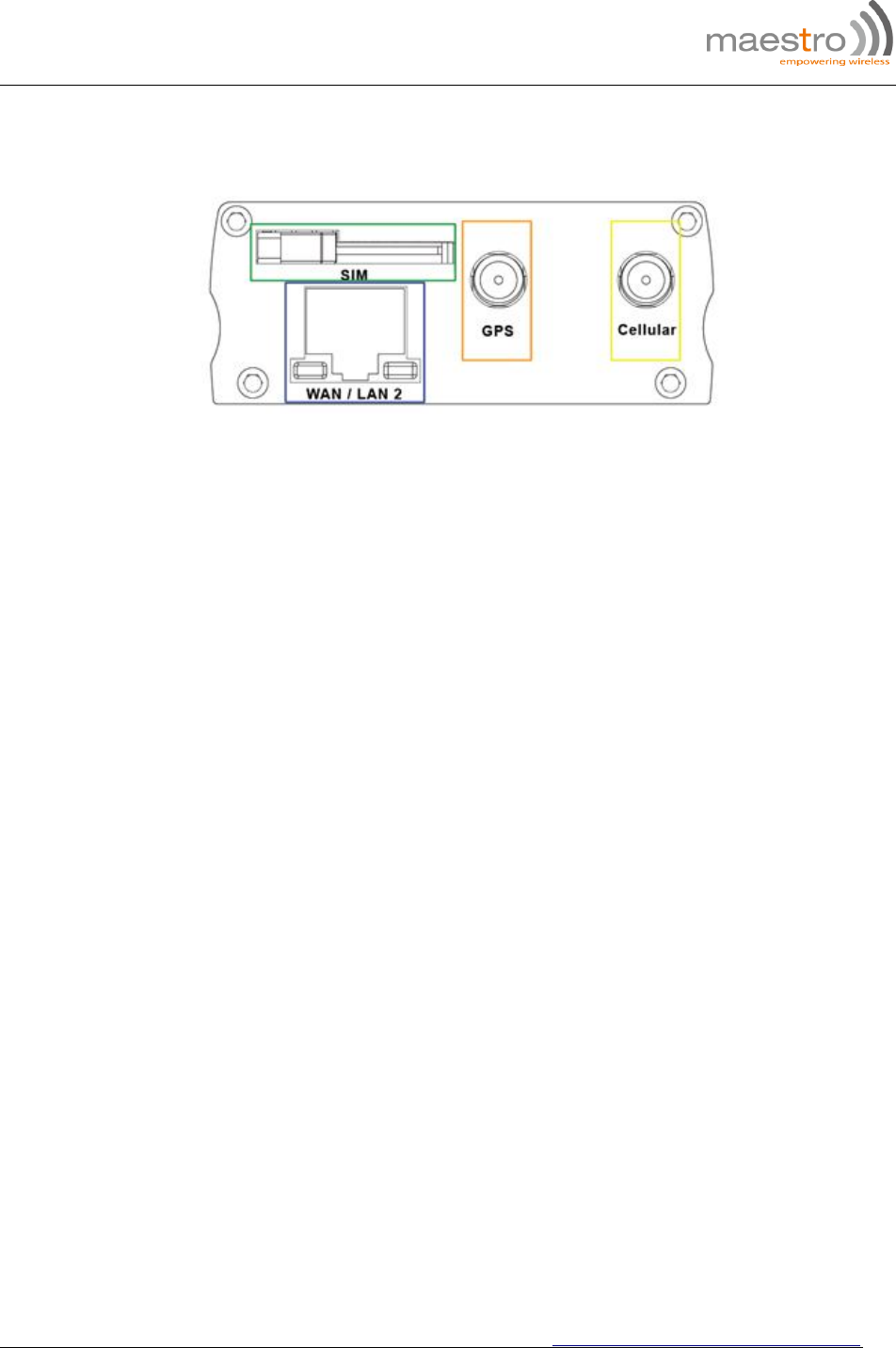
4.2 WAN Panel Details
Figure 4: Maestro Router WAN Panel
Blue - Ethernet port: Can switch from WAN to LAN
Supports PoE (Power over Ethernet): PoE wired Ethernet LANs allow the electrical
current necessary for the operation to be carried by the data cable rather than carried by
power cords thus removing the needs for an external power supply.
Green – Mini SIM slot (2FF)
Orange – GPS / Diversity SMA Antenna Connector: Female (GPS only on LTE version)
Yellow - Cellular SMA Antenna Connector: Female
E220 Series| QUICK START GUIDE http://support.maestro-wireless.com
Page | 10
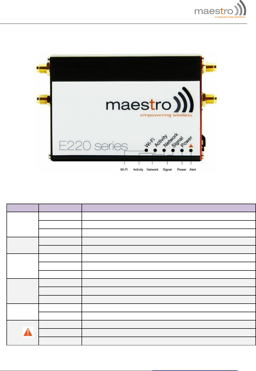
4.3 Front Panel Details
Figure 5: Front Panel
4.3.1 The top panel of Maestro’s E220 Series features 6 LEDs on the front to indicate critical
system information.
Table 3: LED States and Description
Name Color and State
Description
WI-FI
OFF Wi-Fi network is inactive
Blue Flashing Wi-Fi network connection traffic
Blue ON Wi-Fi network is up and activate
Activity OFF Cellular data service is not connected
Amber ON Cellular data service is connected
Network
OFF Device is not registered on a cellular network
Amber Flashing Registered on roaming cellular network
Amber ON Registered on home cellular network
Signal
OFF No signal (CSQ=0 to 5, 97, 98, 99)
Amber ON Strong signal (CSQ > 12)
Amber Flashing Weak signal (CSQ > 6 to 12)
Power OFF Power off
Green ON Power on
Alert
OFF No alert, device is running smoothly
Red Flashing Software fault (crash, issues)
Red ON Hardware fault (high temperature, problem with module or SIM card)
E220 Series| QUICK START GUIDE http://support.maestro-wireless.com
Page | 11
5.0 Connecting Maestro Router
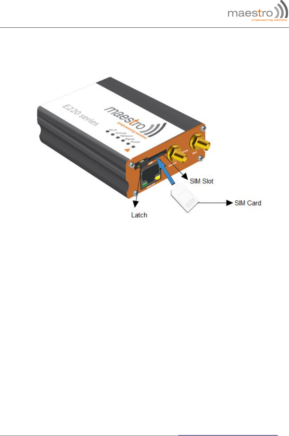
5.1.1 Insert the SIM card in the router as shown below.
Figure 6: Inserting the SIM card in the Maestro router
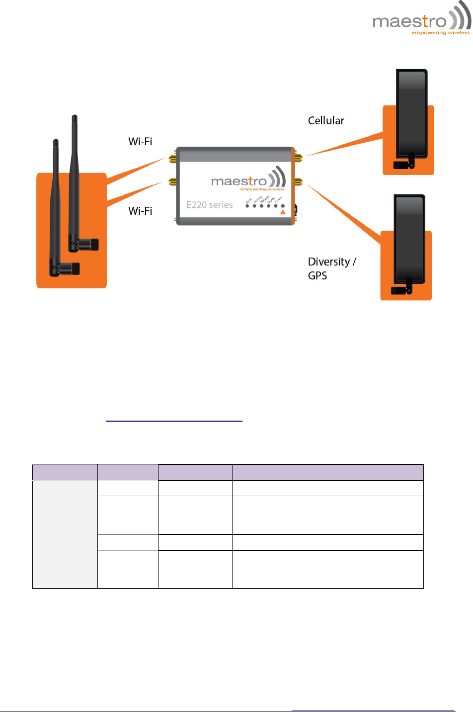
5.1.2 Connect the antenna to the main connector of the E220.
IMPORTANT: Verify the antenna is tightly secured.
5.1.3 Connect the Diversity antenna to the Diversity connector.
E220 Series| QUICK START GUIDE http://support.maestro-wireless.com
Page | 12
Figure 7: Connecting the Wi-Fi & cellular antenna on Maestro router:
5.1.4 If the Maestro Router package includes dual antenna’; connect the Diversity Antenna to
the Diversity Connector.
NOTE: Dual antenna provides RF diversification, which allows for improved signal
strength and thus better performance for both Wi-Fi and cellular,
Certain circumstances and environments may require the use of specific type of
antenna or one mounted in a different location. In such case, Maestro has many
antenna options to choose from, please contact Maestro Support at
support@maestro-wireless.com.
Table 4: E220 series models and auxiliary antennas:
Main Model Auxiliary Comment
Cellular only
E225 Lite N/A
E224 Lite Cellular only
Please ensure that the antenna used is
suitable for the cellular frequencies in use,
for both main and auxiliary connectors
E225 GPS only
E224
E228
2-mode GPS
and cellular
Please ensure that the antenna used is
suitable for the cellular frequencies in use,
for both main and auxiliary connectors
E220 Series| QUICK START GUIDE http://support.maestro-wireless.com
Page | 13
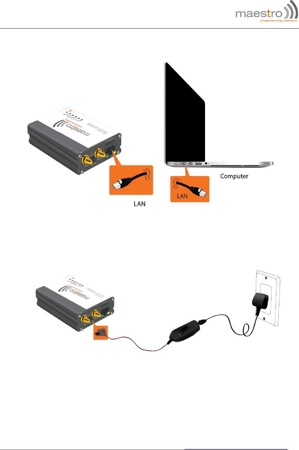
5.1.5 Connect the router LAN port with the computer LAN port.
Figure 8: Connecting the router and computer LAN port
5.1.6 Connect the AC power to the DC in connector, then connect the Micro-Fit connector to
the power input, located on the LAN-side panel of the Maestro Router.
Plug the AC cord into a standard AC receptacle as shown below.
The power LED will light when power is applied.
Figure 9: Connecting the AC power connector
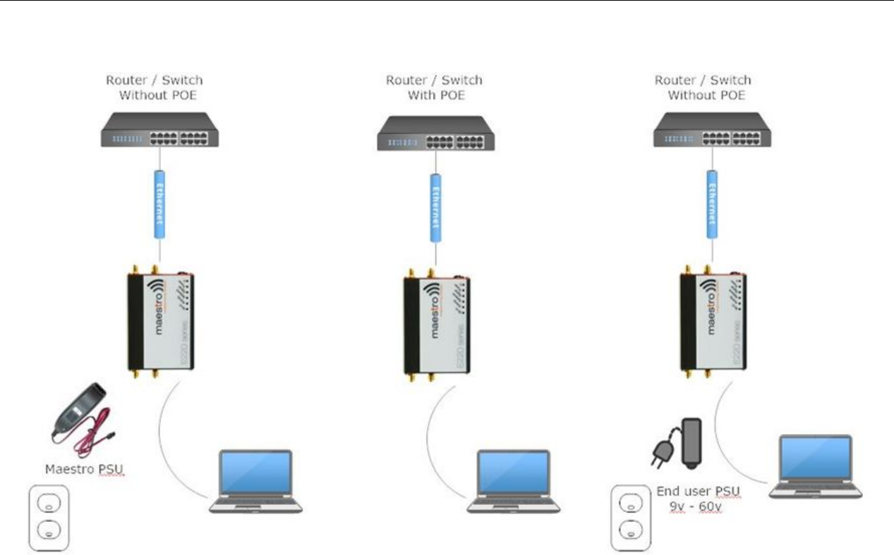
5.1.7 An alternate option is to power the Maestro Router over Ethernet port as the WAN port
supports PoE (Power over Ethernet).
NOTE: Please refer to the section Power over Ethernet on Appendix 1 for connections
example.
E220 Series| QUICK START GUIDE http://support.maestro-wireless.com
Page | 14
6.0 Software Configuration
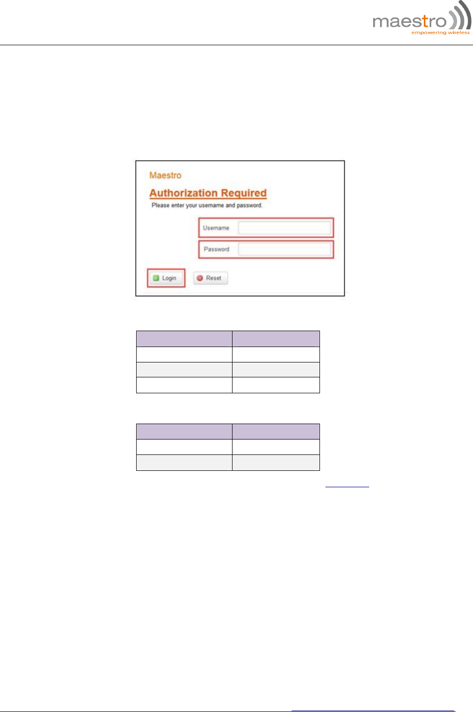
6.1.1 On the computer, open a Web browser and then enter the Maestro routers LAN IP
address. A login dialog window displays.
NOTE: Username and Password are case sensitive.
Figure 10: Login Dialog Box
Table 5: Web Admin Page
Parameters Details
IP Address (LAN) 192.168.1.1
Username admin
Password admin
Table 6: Wi-Fi enabled, with WPA/WPA2 TKIP key
Parameter Details
SSID Maestro
WPA Key W1rele$$
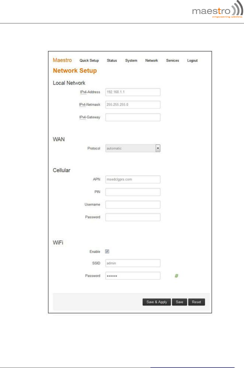
6.1.2 Click Next on the Quick Start Network Configuration Page (figure 11).
6.1.2.1 Configure the network parameters for LAN, WAN, Cellular and Wi-Fi.
6.1.2.2 Alternately, go to Management Settings, import and load predefined settings file.
6.1.2.3 Click Save & Apply to set the configuration.
NOTE: Default WAN, LAN and cellular connection settings:
6.1.2.4 WAN connection – Automatic (DHCP – Automatic IP address lookup).
6.1.2.5 Active DHCP with starting IP address: 192.168.1.100 with poll off 100 clients.
6.1.2.6 WAN as automatic IP, with Cellular backup.
E220 Series| QUICK START GUIDE http://support.maestro-wireless.com
Page | 15
6.1.2.7 Cellular default APN is “internet”
Figure 11: Quick Start Network Configuration Page
E220 Series| QUICK START GUIDE http://support.maestro-wireless.com
Page | 16
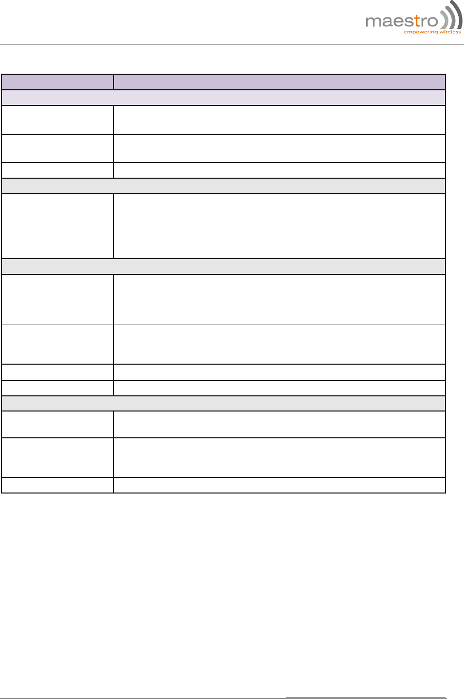
Table 7: Quick Start Network Configuration Page
Screen Element Description
Local Network
IPv4-Address Enter the IPv4 Address of LAN interface.
The default IPv4 Address is 192.168.1.1
IPv4-Netmask Enter the IPv4 Subnet Mask of LAN interface.
The default Netmask is 255.255.255.0
IPv4-Gateway Enter the Gateway IPv4 of the Gateway.
WAN
Protocol
Select the WAN protocol from the available options:
Manual
Automatic
PPPoE
The default WAN protocol is selected as Automatic.
Cellular
APN
Enter the APN provided by the cellular network operator.
Access Point Name (APN) is the name (Web address) of an access point for
LTE data connection. Generally, wireless cellular network operator provides
the APN to their end users.
PIN
Enter the PIN of the SIM card.
SIM card Personal Identification Number (PIN) is used to lock the card,
preventing unauthorized phone calls or access to cellular data.
Username Enter the login name.
Password Enter the password.
Wi-Fi
Enable By default, Wi-Fi interface is enabled every time the Maestro Router reboots.
Click and disable the Wi-Fi interface if you do not want to use them.
SSID
Service Set Identifier (SSID) is a sequence of characters, which uniquely
names a wireless local area network (WLAN).
The default SSID is Maestro.
Password The default password is W1rele$$.

E220 Series| QUICK START GUIDE http://support.maestro-wireless.com
Page | 17
7.0 Conformity
7.1 Federal Communications Commission (FCC) Compliance Statement
7.1.1 This device complies with part 15 of the FCC Rules. Operation is subject to the following
two conditions:
This device may not cause harmful interference.
This device must accept any interference received, including interference that may cause
undesired operation.
7.1.2 This device has been tested and found to comply with the limits for a Class B digital
pursuant to Part 15 of the FCC Rules. These limits are designed to provide reasonable
protection against harmful interference in a residential installation. This equipment generates,
uses and can radiate radio frequency energy.
7.1.2.1 It not installed and used in accordance with the instructions, may cause harmful
interference to radio communications. here is no guarantee that interference will not
occur in a particular installation.
7.1.2.2 If this equipment does cause harmful interference to radio or television reception,
which can be determined by turning the equipment off and on, the user is
encouraged to try to correct the interference by one or more of the following
measures:
Reorient or relocate the receiving antenna.
Increase the separation between the equipment and receiver.
Connect the equipment into an outlet on a circuit different from that to which the
receiver is connected.
Consult the dealer or an experienced radio/TV technician for help.
7.1.3 FCC Caution:
7.1.3.1 Changes or modifications not expressly approved by the party responsible for
compliance could void the user’s authority to operate the equipment.
7.2 FCC RF Exposure statement
This device complies with FCC radiation exposure limits set forth for an uncontrolled environment.
In order to avoid the possibility of exceeding the FCC radio frequency exposure limits, human
proximity to the antenna shall not be less than 20cm (8 inches) during normal operation.
7.3 ISED Notice
This device complies with Innovation, Science and Economic Development Canada license-
exempt RSS standard(s). Operation is subject to the following two conditions:
(1) this device may not cause interference, and
(2) this device must accept any interference, including interference that may cause undesired
operation of the device.

E220 Series| QUICK START GUIDE http://support.maestro-wireless.com
Page | 18
Le présent appareil est conforme aux CNR Innovation, Sciences et Développement économique
Canada applicables aux appareils radio exempts de licence. L'exploitation est autorisée aux deux
conditions suivantes :
(1) l'appareil ne doit pas produire de brouillage, et
(2) l'utilisateur de l'appareil doit accepter tout brouillage radioélectrique subi, même si le
brouillage est susceptible d'en
This Class B digital apparatus complies with Canadian ICES-003.
Cet appareil numérique de la classe B est conforme à la norme NMB-003 du Canada.
IC: 20055-E228F7, 20055-E224LITEF2, 20055-E224LITEF4, 20055-E225LITEF3, 20055-E225F3,
20055-E228F2, 20055-E228F5
7.4 ISED RF Exposure Information
This device complies with ISED radiation exposure limits set forth for an uncontrolled
environment. In order to avoid the possibility of exceeding the ISED radio frequency exposure
limits, human proximity to the antenna shall not be less than 20cm (8 inches) during normal
operation.
Cet appareil est conforme aux limites d'exposition aux rayonnements de la ISED CNR-102
définies pour un environnement non contrôlé. Afin d'éviter la possibilité de dépasser les limites
d'exposition aux fréquences radio de la ISED CNR-102, la proximité humaine à l'antenne ne doit
pas être inférieure à 20 cm (8 pouces) pendant le fonctionnement normal.
8.0 Appendix:
8.1 Pin Power Cable Schematic
Figure 12:
_____________________________________________________________________________________
8.2 Power over Ethernet
Figure 13: PoE
_____________________________________________________________________________________
8.3 RS485 wiring diagram
Figure 14: Half Duplex (Left) RS485 Full Duplex (Right)

_____________________________________________________________________________________
8.4 Certified antenna
Dipole Wi-Fi antenna:
5 dBi high performance antenna
RP-SMA(M) hinged antenna
RoHS compliant
Peak gain: 3.8 dBi @2.4 GHz ~ 2.5 GHz
WWAN antenna:
Dipole 4G swivel blade antenna
Performance across the LTE frequency bands
698-960 / 1710-2170 / 2500-2700 MHz
Up to 2 dBi gain
SMA connector
RoHS compliant product
8.5 Selection of antenna
Selection of Wi-Fi antenna:
Dipole, Peak Gain < 3.8 dBi @ 2.4 GHz ~ 2.5 GHz
Selection of antenna type:
Using the same dipole antenna type as certified module & Modem for FCC as above or external antenna with length > 20
cm.