Magic Chef 9875XYB User Manual BUILT IN OVEN ELECTRIC Manuals And Guides LR707472
MAGIC CHEF Built In Oven, Electric Manual LR707472 MAGIC CHEF Built In Oven, Electric Owner's Manual, MAGIC CHEF Built In Oven, Electric installation guides
User Manual: Magic Chef 9875XYB 9875XYB MAGIC CHEF BUILT-IN OVEN - ELECTRIC - Manuals and Guides View the owners manual for your MAGIC CHEF BUILT-IN OVEN - ELECTRIC #9875XYB. Home:Kitchen Appliance Parts:Magic Chef Parts:Magic Chef BUILT-IN OVEN - ELECTRIC Manual
Open the PDF directly: View PDF ![]() .
.
Page Count: 4
IMPORTANT -PLEASE KEEP FOR USE OF THE LOCAL ELECTRICAL INSPECTOR
READ "SAFETY PRECAUTIONS" IN USE & CARE BOOK BEFORE USING OVEN
In order to assure the best results in service, proper operation and maximum efficiency, the original installation and adjustment
should be made by your dealer, his authorized agent, or by your local utility company before you attempt to operate the oven.
LOCATION
Place oven where it will be welt lighted. For proper baking and cooking results, oven must be level. Use a spirit level on center
oven rack to level. THIS ELECTRIC OVEN IS APPROVED FOR INSTALLATION IN COMBUSTIBLE CABINETRY. SEE
INSTALLATION DIAGRAM FOR THE OVEN ON THE REVERSE SIDE OF THE INSTRUCTION SHEET.
OUTSIDE WIRING
Your local utility company will tell you whether the present electric service to your home is adequate. It may be necessary to
increase the size of the wiring to the house and service switch to take care of the electrical load demanded by the oven and/or
top section. The wattage (K. W. rating) load for the oven is specified on the name plate on the unit.
HOUSE WIRING
Most local building regulations and codes require that all electrical wiring be done by licensed electricians. All wiring should
conform to local or Canadian Electrical Codes. This oven requires a single phase 120/240 or a 120/208 volt, 60 Hz, AC circuit.
Wiring codes require that a separate circuit be run from the main entrance panel to the oven, The main entrance panel is to
be equipped with a separate disconnect switch and fuse as required by the local or canadian electrical codes.
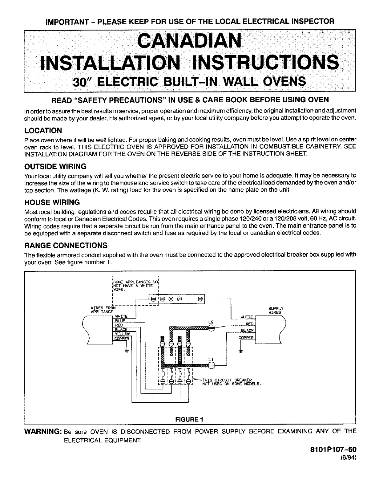
RANGE CONNECTIONS
The flexible armored conduit supplied with the oven must be connected to the approved electrical breaker box supplied with
your oven. See figure number t.
FIGURE 1
WARNING: Be sure OVEN IS DISCONNECTED FROM POWER SUPPLY BEFORE EXAMINING ANY OF THE
ELECTRICAL EQUIPMENT.
8101 P107-60
(6/94)
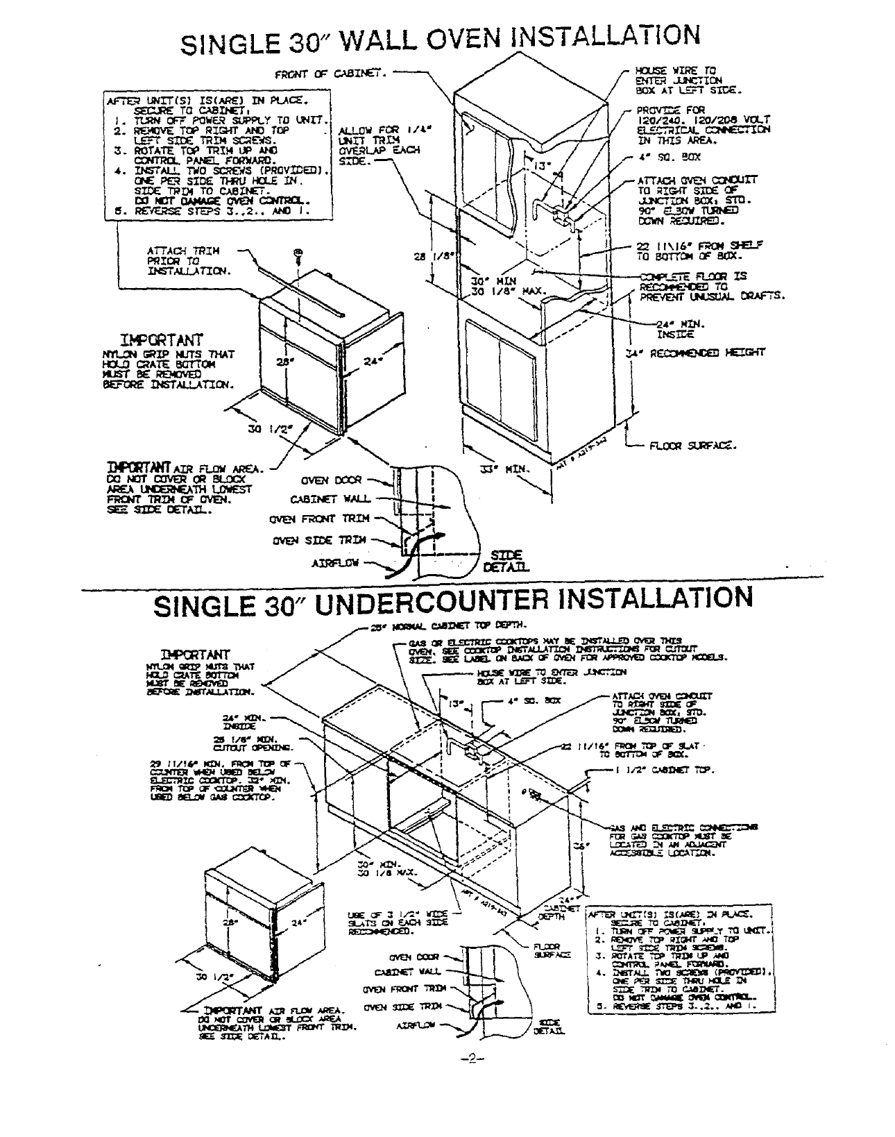
SINGLE 30" WALL OVEN INSTALLATION
SINGLE 30" UNDERCOUNTER INSTALLATION
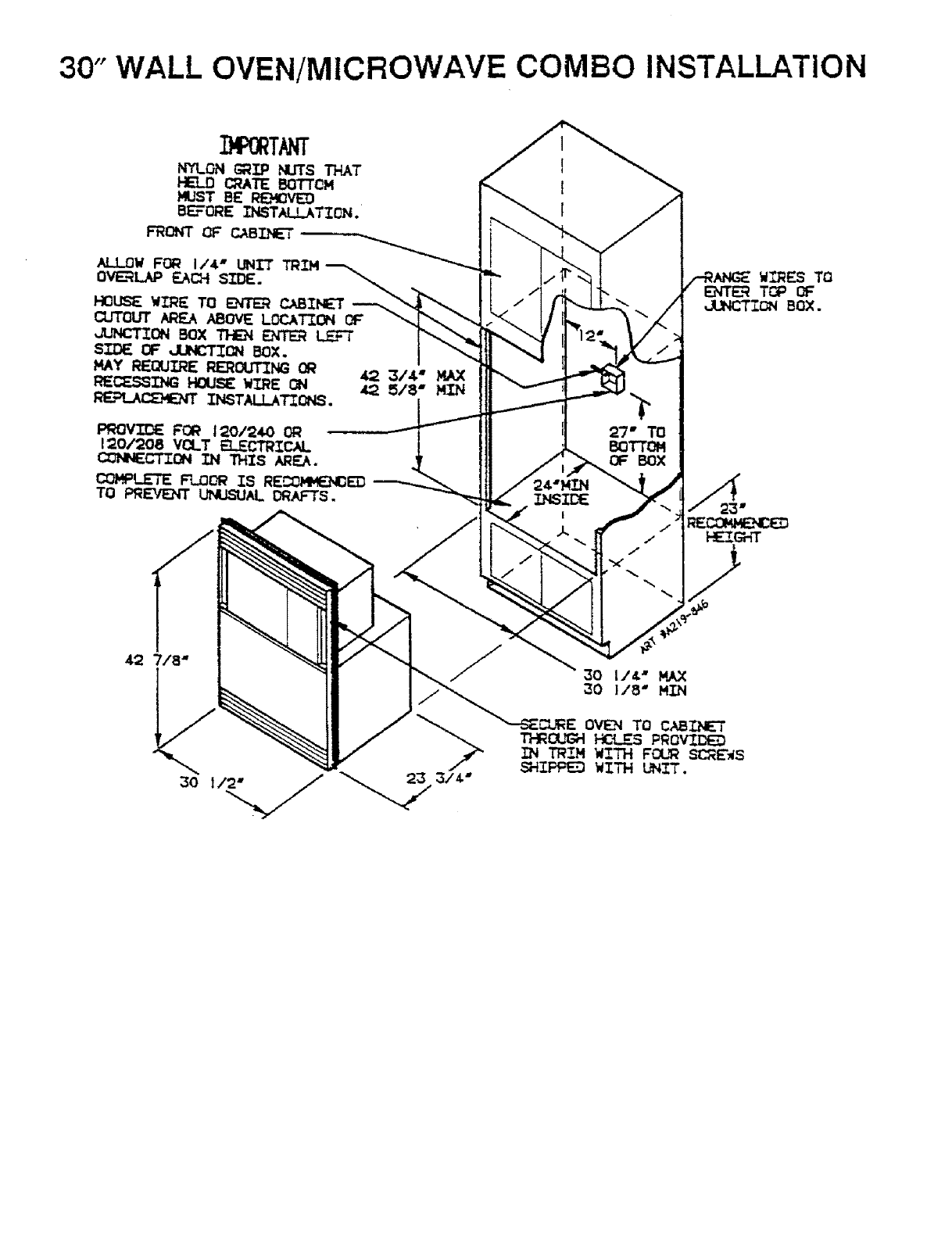
30" WALL OVEN/MICROWAVE COMBO INSTALLATION
OVI_ TO CABIhL='T
13-RGUGH HC_I_S PROVII_
IN TRIM WI_3_ FOUR SCR_*S
SHiFF_ WITH L_IT.
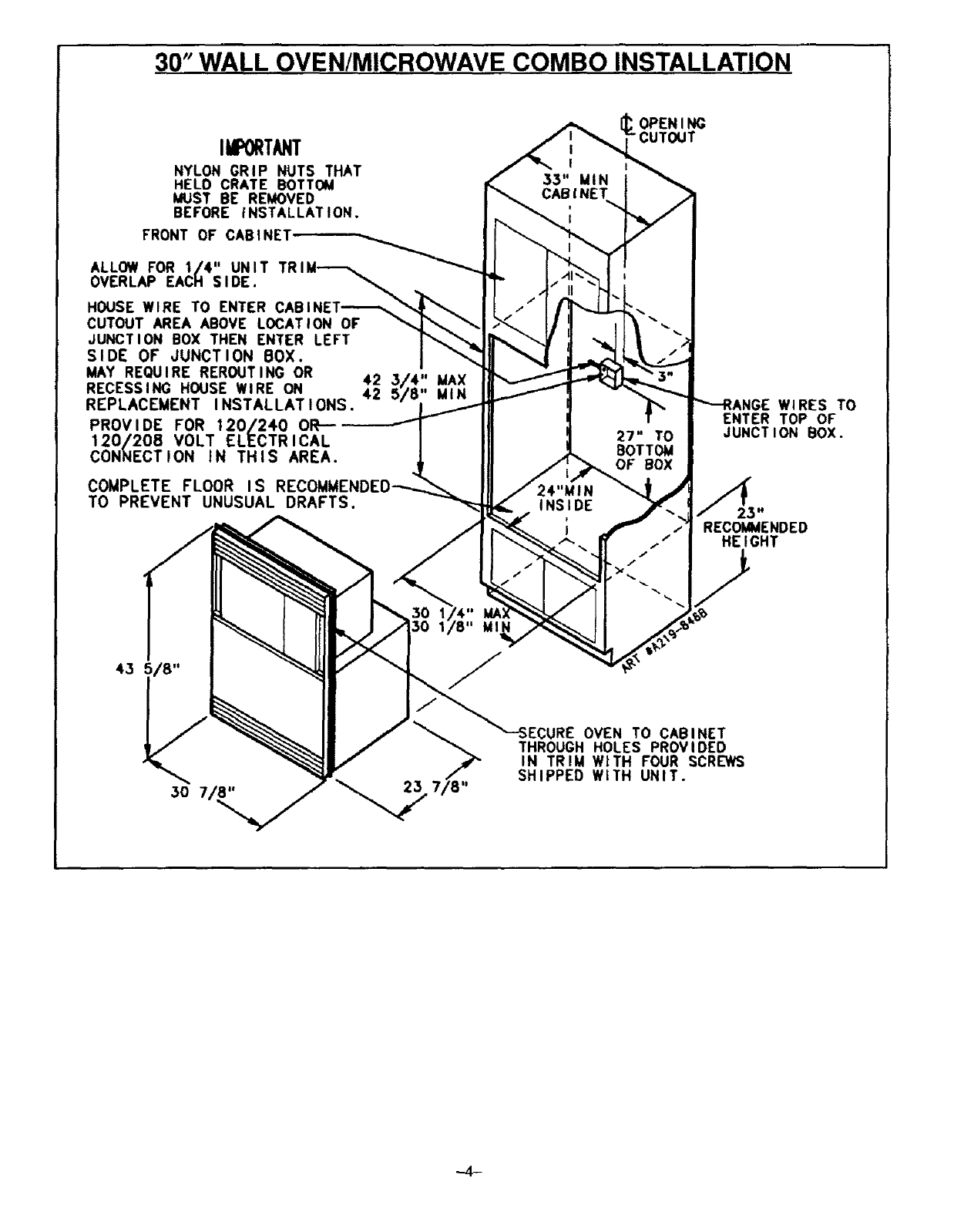
30" WALL OVEN/MICROWAVE COMBO INSTALLATION
III O T/ IT
NYLON GRiP NUTS THAT
HELO CRATE BOTTOM
MUST BE REMOVED
BEFORE iNSTALLATION.
FRONT OF CABINET
ALLOW FOR 1/4" UNIT
OVERLAP EACH SIDE.
HOUSE WIRE TO ENTER CABINET-_
CUTOUT AREA ABOVE LOCATION OF
JUNCTION BOX THEN ENTER LEFT
SIDE OF JUNCTION BOX.
MAY REQUIRE REROUTING OR
RECESSING HOUSE WIRE ON
REPLACEMENT INSTALLATIONS,
PROVIDE FOR 120/240 0R--
120/208 VOLT ELECTRICAL
CONNECTION IN THIS AREA.
COMPLETE FLOOR IS RECOMMEN
TO PREVENT UNUSUAL DRAFTS,
42 3/4" MAX
42 5/8" MIN
OPENING
CUTOUT
"-"SECURE OVEN TO CABINET
THROUGH HOLES PROVIDED
IN TRIM WITH FOUR SCREWS
SHIPPED WITH UNIT.
WIRES TO
ENTER TOP OF
JUNCTION BOX.
RECOMMENDED
HE I GHT
,,_4-
