Magna Electronics MMR24 24 GHz MMR Sensor User Manual 24 GHz Users Manual
Autoliv ASP, Inc. 24 GHz MMR Sensor 24 GHz Users Manual
Contents
- 1. 06 Users Manual Preliminary 1
- 2. 07 Installation Manual 2
07 Installation Manual 2
REVISION HISTORY
Rev
Description
Date
Apprv’d
000 Initial Release per ECO 127519 Ref. PLM
001 Update after customer review Ref. PLM
002 Update 5.3.1, add 5.3.8 Ref. PLM
003 Update 5.3.1 RX Distance Ref. PLM
TITLE: Installation Specifications and User Manual, C6 Radar
(24 GHz MMR, 24 GHz SRR, 24 GHz MRR) DOCUMENT NO: E805913
INSTALLATION SPECIFICATION REV. 003, PAGE 1 OF 12
AEL, Inc.
1011B Pawtucket Blvd.
Lowell, MA 01853
ATTENTION
USER OF THIS DOCUMENT IS
RESPONSIBLE FOR
DETERMINING CURRENT
REVISION LEVEL BEFORE
USING DOCUMENT.
©
AUTOLIV INC. THIS DOCUMENT AND
THE DATA DISCLOSED HEREIN OR
HEREWITH IS PROPRIETARY AND MAY
NOT BE REPRODUCED, USED OR
DISCLOSED IN WHOLE OR IN PART
WITHOUT WRITTEN PERMISSION
FROM AUTOLIV INC.

Title Installation Specifications and User Manual, Radar
Sensor, C6 Doc. No. E805913
INSTALLATION SPECIFICATION Rev. 003, Page 2 of 12
1.0 PURPOSE/SCOPE
This document describes the specifications for installation of type C6 Radar Sensors.
2.0 MATERIALS/EQUIPMENT
N/A
3.0 APPLICABLE DOCUMENTS
Outline see Fig 1.
DIN 40050-9 IP6K9K
IEC 68-2-6 Fc IEC 68-2-7 IEC68-2-10 IEC68-2-11 Ka
IEC 668-2-14Nb IEC 68-2-27 IEC 68-2-29 IEC68-2-30
IEC68-2-32 IEC68-2-38 IEC68-2-50 IEC68-2-51
IEC68-2-52 IEC68-2-56 IEC68-2-64Fh IEC529, 13.4
SAE J1211 SAE J1812 SAE J1879
4.0 DEFINITIONS
N/A
5.0 SPECIFICATIONS
5.1. Preface
This chapter describes the specifications to install C6 radar sensors into vehicles.
These specifications shall be complied with to enable the specified characteristics of the
sensors as well as the complete system. Due to the various installation situations and
applications, a measurement check is required to verify the actual installation
implementation.
5.2. C6 Sensors
This chapter describes the characteristics relevant to the installation of C6 sensors in
vehicles. Note that there are three types of C6 sensors, each supporting various
applications as follows:
C6 Mid Range Radar (24 GHz MRR)
Model # 6208428
– used for medium range applications such as Forward collision Warning.
C6 Short Range Radar (24 GHz SRR)
Model # 6221569
– used for short range applications such as ACC Stop and Go, Blind Spot Monitoring.
C6 Multi Mode sensor (24 GHz MMR)
Model # 6234448
– combined SRR and MRR functionality.
Unless otherwise stated the specifications contained in this document apply to all C6
sensor types.

Title Installation Specifications and User Manual, Radar
Sensor, C6 Doc. No. E805913
INSTALLATION SPECIFICATION Rev. 003, Page 3 of 12
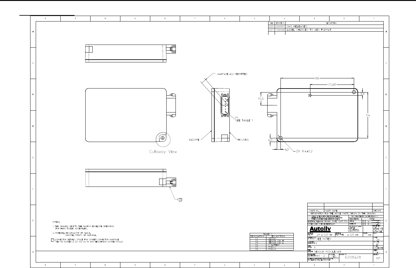
5.2.1. Dimensions and Weight of the C6 Sensor
Figure 1 shows the dimensions of the C6 sensor and details the mounting of the
sensor.
Please refer to Fig. 1 for the detailed drawing.
Sensor weight: 150 grams max.
Title:
Installation Specifications and User Manual, Radar Sensor, C6 Doc. No. E805913
INSTALLATION SPECIFICATION Rev. 003, Page 4 of 12
5.0 SPECIFICATIONS
Figure 1
IMPORTANT NOTE: The two mounting holes are not specified for mounting the complete sensor. They do not provide the
mechanical properties to keep the sensor in place. They shall be used to fix the sensor in a mounting bracket. Mounting tabs
are to be fastened tight to mounting bracket using appropriate fastener. Maximum strength per tab is 270 N.
Title:
Installation Specifications and User Manual, Radar
Sensor, C6 Doc. No. E805913
INSTALLATION SPECIFICATION Rev. 003, Page 5 of 12
5.0 SPECIFICATIONS
5.2 C6 Sensor (cont’d)
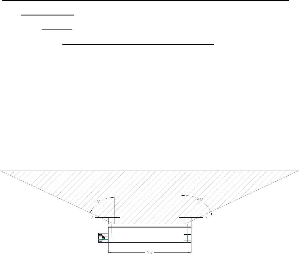
5.2.2 Keep-Out Zone / Azimuth Angle Measurement Range
Figure 2 displays the keep out area of the C6 sensor.
Within the detection area of the antennas there must not be objects like screws,
mounting brackets, license plates etc. The impact reducing foam material, clips
or fascia laminations has to be avoided in that area.
Within the keep out zone of the antennas there must be no vertical character
lines present in the fascia (see 5.3.5). Mounting bracket material shall not enter
the keep out zone. Bracket retention features which interface with the surface of
the sensor radome shall not enter the keep out zone noted in Section 5.2.5
The keep out zone in the azimuth direction is ±65°. The angle is established
7mm from the edge of the sensor.
Figure 2
Title:
Installation Specifications and User Manual, Radar
Sensor, C6 Doc. No. E805913
INSTALLATION SPECIFICATION Rev. 003, Page 6 of 12
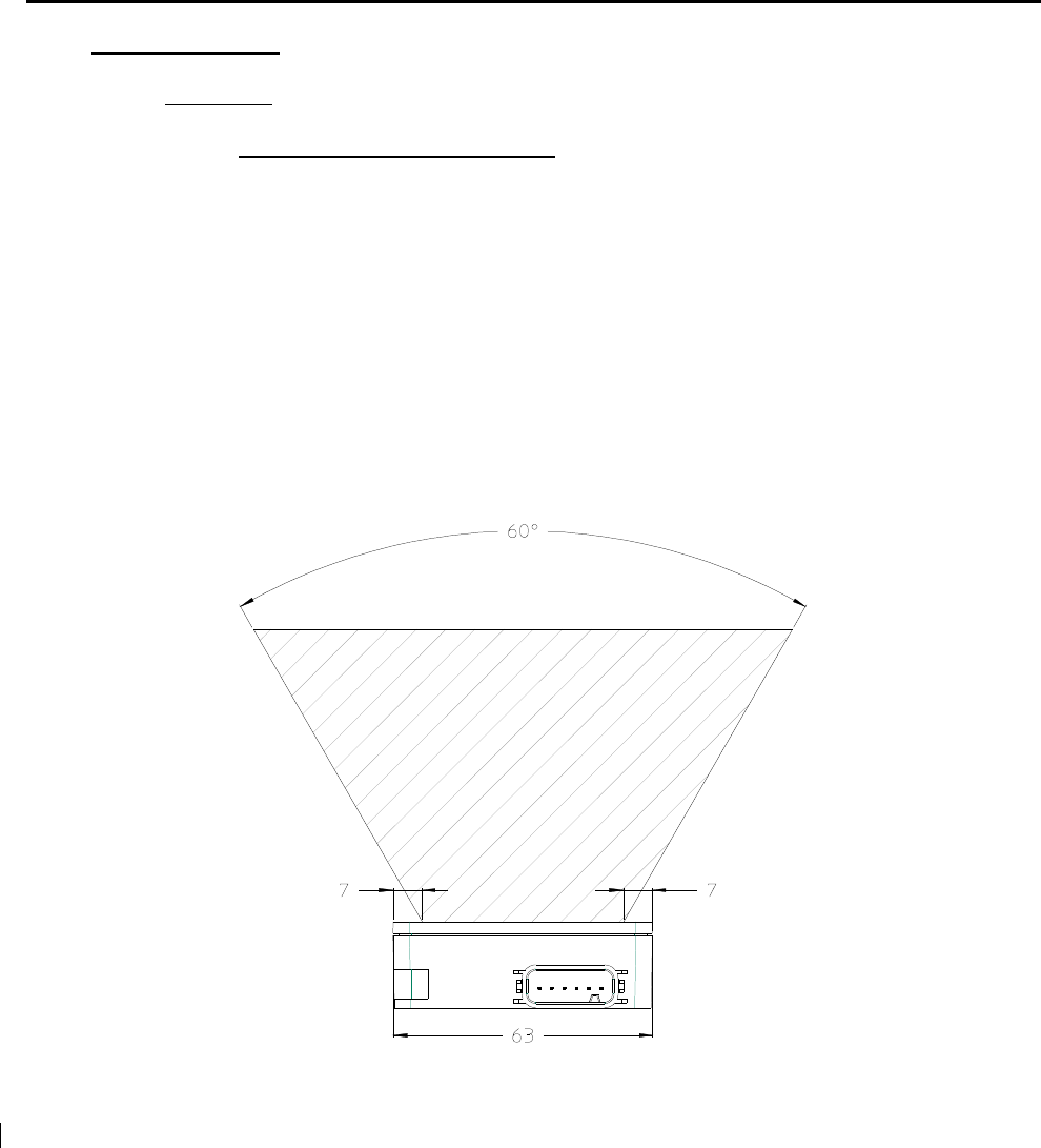
5.0 SPECIFICATIONS
5.2 C6 Sensor (cont’d)
5.2.3 Keep-out zone, Angle Elevation
Within the elevation keep out zone there must not be metal parts like screws,
mounting brackets, license plate etc. The impact reducing foam material, clips or
fascia laminations has to be avoided in that area.
Within the keep out zone of the antennas there must be no vertical character
lines present in the fascia (see 5.3.5). Mounting bracket material shall not enter
the keep out zone. Bracket retention features which interface with the surface of
the sensor radome shall not enter the keep out zone noted in Section 5.2.5
The elevation material keep out zone in elevation is ±30°. This angle is
established 7mm from the edge of the sensor.
Figure 3
Title:
Installation Specifications and User Manual, Radar
Sensor, C6 Doc. No. E805913
INSTALLATION SPECIFICATION Rev. 003, Page 7 of 12
5.2 C6 Sensor (cont’d)
5.2.4 Section deleted
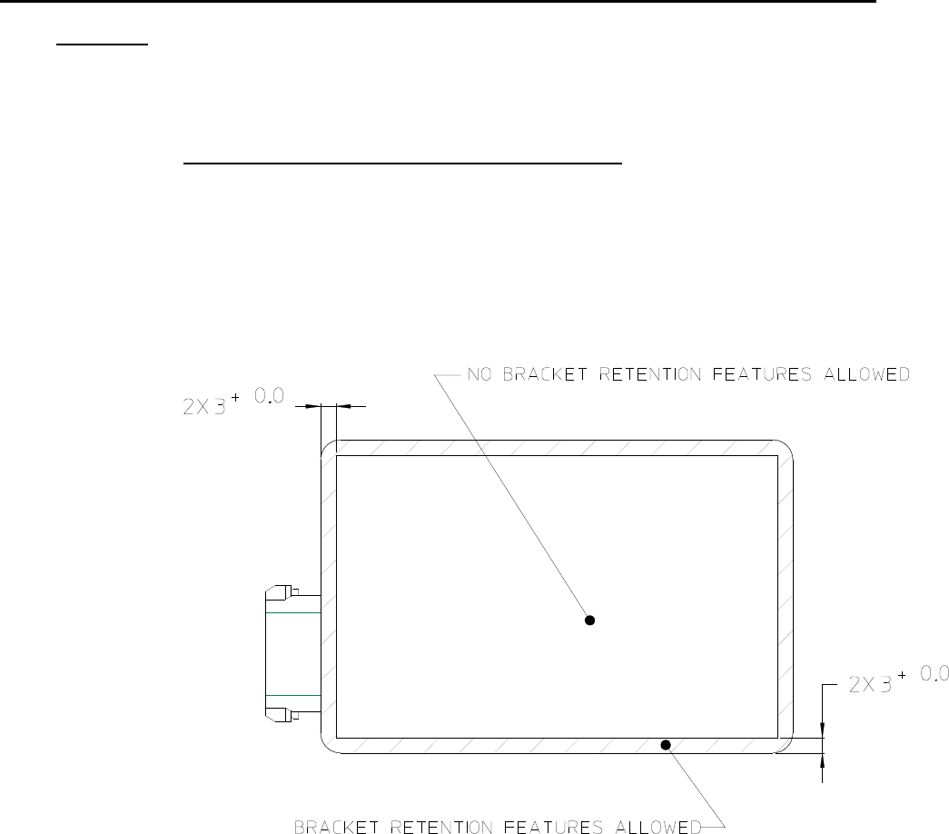
5.2.5 Bracket to sensor retention features keep out zone
Bracket retention features which are used to hold the sensor into the bracket,
shall be made of non-conductive material, and protrude into the face of the
sensor radome with enough overlap to overcome any variability in the bracket (ie.
bracket to sensor gap, material distortion). A general guideline is to create a
retention feature with overlap which is positioned in the allowable shaded area
outlined below (Figure 3b).
Figure 3b
Title:
Installation Specifications and User Manual, Radar
Sensor, C6 Doc. No. E805913
INSTALLATION SPECIFICATION Rev. 003, Page 8 of 12
5.3 Installation Specifications for Individual Sensors
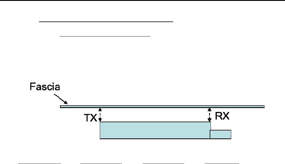
5.3.1 Distance to the Bumper Material
The distance of the C6 Sensor to the bumper shall be as shown below.
An installation with the sensor parallel to fascia is preferred. If this is not
possible any combination of TX and RX distance within the table below
are allowed.
Figure 4
Sensor Model# Sensor Type RX Distance TX Distance
6208428 Mid Range Radar 5mm-25mm 5mm-25mm
6221569 Short Range Radar 5mm-25mm 5mm-25mm
6234448 Multimode Sensor 5mm-25mm 5mm-25mm
5.3.2 Section Deleted
Title:
Installation Specifications and User Manual, Radar
Sensor, C6 Doc. No. E805913
INSTALLATION SPECIFICATION Rev. 003, Page 9 of 12
5.0 SPECIFICATIONS
5.3 Installation Specifications for Individual Sensors (cont’d)
5.3.3 Effect of Type- and Thickness of Fascia Material
Autoliv has examined various fascia material samples with a thickness
of 2.5 – 4 mm. Fascia loss effects can be optimized by proper control
of the material thickness and dielectric constant. Thickness should be
uniform in front of the radar sensor.
Thickness and dielectric constant must be controlled to a tolerance of
±10% max to ensure optimal performance.
New fascia material shall be evaluated by Autoliv for its characteristics
at RF antenna frequency.
5.3.4 Effect of the Paint
Effect of paint is detailed in Appendix A. New paint material shall be
evaluated by Autoliv.
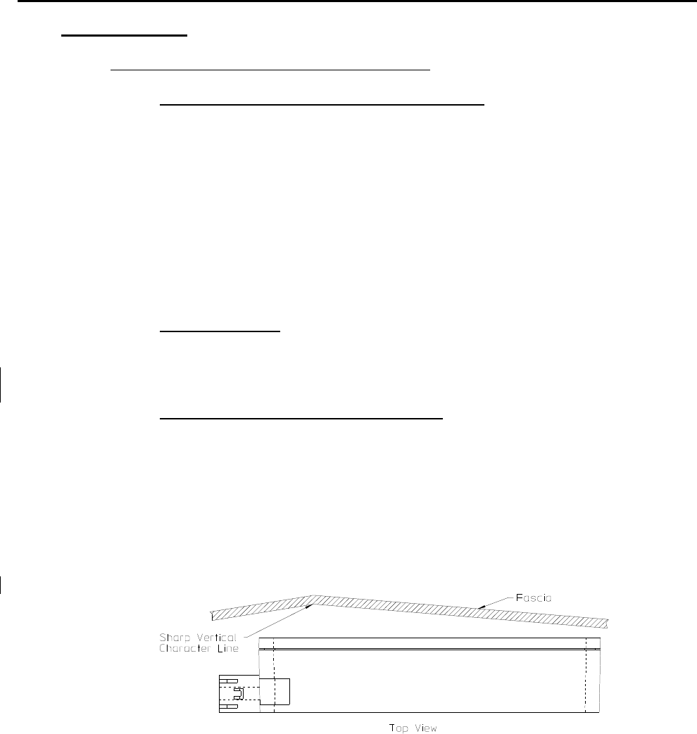
5.3.5 Smoothness of Fascia in Front of Antenna
Avoid sharp vertical or near vertical character lines in front of sensor
antenna. Horizontal character lines seem to have little effect on sensor
performance.
Fascias with textured surfaces shall be evaluated by Autoliv to
characterize the effects on sensor performance.
Figure 6
Title:
Installation Specifications and User Manual, Radar
Sensor, C6 Doc. No. E805913
INSTALLATION SPECIFICATION Rev. 003, Page 10 of 12
5.0 SPECIFICATIONS
5.3 Installation Specifications For Individual Sensors (cont’d)
5.3.6 Protection from Mud and Dirt Buildup
There will be performance degradation if excessive buildup occurs on the
antenna areas and especially for wet mud. Therefore Autoliv strongly
recommends the sensor mounting include provisions to protect the antenna face
from dirt and mud accumulation. The mounting concept should completely
protect the face of the antenna to prevent mud and dirt from entering the free
space between the sensor radome and the fascia, yet a small weep hole at the
bottom of the bracket is required to allow condensation to dissipate.
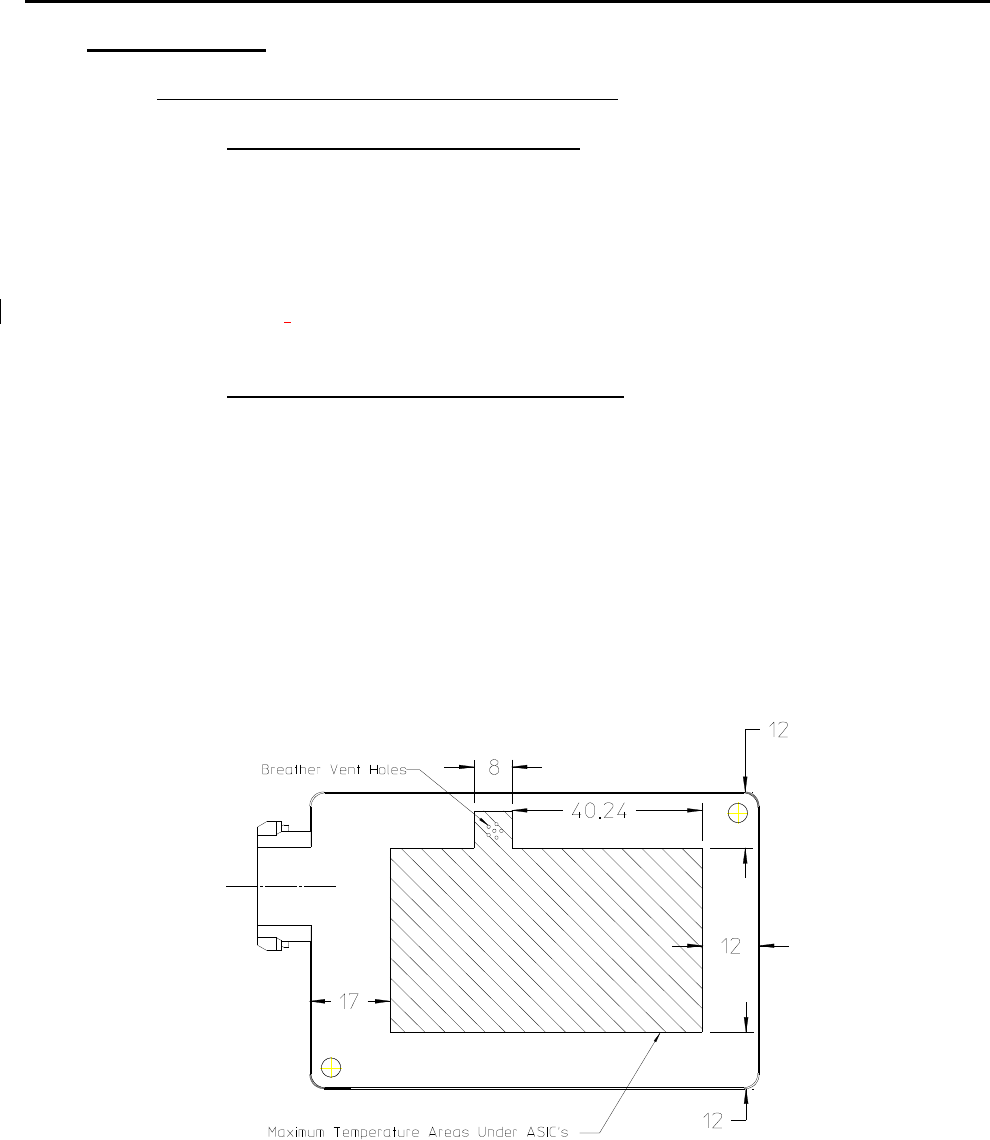
5.3.7 Sensor Mounting Thermal Considerations
The sensor is specified to operate in a –40
°
to +85°C ambient, still air
environment. Natural convection and venting from the front and
backside surfaces of the sensor to the ambient air is assumed.
Therefore the mounting concept shall leave both the front radome and
backside area of the sensor exposed to the ambient air. Minimum area
to be left for the backside exposed is as shown below. Bracket
reinforced structure such as cross bars are allowed if approximately
80% of backside area remains exposed to ambient air for heat
dissipation. Maximum surface temperature in this region is +115°C at a
maximum ambient of +85°C.
Figure 7

Title:
Installation Specifications and User Manual, Radar
Sensor, C6 Doc. No. E805913
INSTALLATION SPECIFICATION Rev. 003, Page 11 of 12
5.3.8 Mounting Bracket Design and Vehicle Mounting
In addition to the mounting bracket design being consistent with the keep out zones
described in this document the bracket must also provide the following:
- The mounting bracket shall prevent sensor movement or vibration in x, y, or z
direction with respect to the bracket.
- The bracket shall be mounted to vehicle in manner to prevent sensor
movement or vibration in x, y, or z direction with respect to the fascia surface that is in the
sensor field view (sensor keep out zone). To achieve this it is preferred that the bracket be
firmly attached to the inner surface of the fascia.
- For cases where a chassis mounted bracket is only option there shall be design
considerations in place to prevent movement or vibration in x, y, or z direction with respect to
the fascia surface that is in the sensor field view (sensor keep out zone).
6.0 C6 SENSOR SYSTEM
The following observations refer to the combination of several C6 Sensors into one
sensor system. Many applications require several sensors networked together to
achieve the desired function. The sensors should be placed in the best possible
location for optimal coverage and range performance relative to the specific
applications. The optimal locations will be highly dependent on the desired
applications and the bumper dimensions. Autoliv can perform analysis and
characterization to determine sensor locations to best achieve a desired performance.
Attention should be paid that the installation specifications for individual sensors from
chapter 5 are maintained. Due to the various installation situations and applications, a
measurement check is required to verify the actual installation implementation.

Title:
Installation Specifications and User Manual, Radar
Sensor, C6 Doc. No. E805913
INSTALLATION SPECIFICATION Rev. 003, Page 12 of 12
APPENDIX A
EFFECT OF PAINT
Depending upon the type of paint, number of coatings, base coats used, etc. the
attenuation of the radar signal was measured between 2 and 5 dB (corresponds to
reduction of coverage between 11 and 25%). Because attenuation has significant
impact on performance, prior inspection of the material and paint samples are
suggested. Autoliv can characterize painted fascia samples to determine the radar
signal loss effects. Autoliv sensor specifications assume a maximum signal loss (2-
way) of 4 dB due to fascia effects. Materials and paints that exhibit greater than 4 dB
loss will degrade the specified performance. As noted in 5.3.3 performance can be
optimized by proper control of the fascia material thickness and dielectric constant.