Magna Electronics MRR25 24GHz SRS Sensor User Manual 08 Installation Instructions
Autoliv ASP, Inc. 24GHz SRS Sensor 08 Installation Instructions
Contents
- 1. 08 user manual
- 2. 08 Installation Instructions
08 Installation Instructions
REVISION HISTORY
Rev
Description
Date
Apprv’d
000 Initial Release per ECO 127519 Ref. PLM
TITLE: Installation Specifications and User Manual, 24 GHz
Radar Sensor, Model 6208428 DOCUMENT NO: E814702
INSTALLATION SPECIFICATION REV. 000, PAGE 1 OF 16
AEL, Inc.
1011B Pawtucket Blvd.
Lowell, MA 01853
ATTENTION
USER OF THIS DOCUMENT IS
RESPONSIBLE FOR
DETERMINING CURRENT
REVISION LEVEL BEFORE
USING DOCUMENT.
©
AUTOLIV INC. THIS DOCUMENT AND
THE DATA DISCLOSED HEREIN OR
HEREWITH IS PROPRIETARY AND MAY
NOT BE REPRODUCED, USED OR
DISCLOSED IN WHOLE OR IN PART
WITHOUT WRITTEN PERMISSION
FROM AUTOLIV INC.

Title Installation Specifications and User Manual, 24 GHz
Radar Sensor, Model 6208428 Doc. No. E814702
INSTALLATION SPECIFICATION Rev. 000, Page 2 of 16
1.0 PURPOSE/SCOPE
This document describes the specifications for installation of type 24 GHz Radar Sensors.
2.0 MATERIALS/EQUIPMENT
N/A
3.0 APPLICABLE DOCUMENTS
Outline see Fig 1.
DIN 40050-9 IP6K9K
IEC 68-2-6 Fc IEC 68-2-7 IEC68-2-10 IEC68-2-11 Ka
IEC 668-2-14Nb IEC 68-2-27 IEC 68-2-29 IEC68-2-30
IEC68-2-32 IEC68-2-38 IEC68-2-50 IEC68-2-51
IEC68-2-52 IEC68-2-56 IEC68-2-64Fh IEC529, 13.4
SAE J1211 SAE J1812 SAE J1879
4.0 DEFINITIONS
N/A
5.0 SPECIFICATIONS
5.1. Preface
This chapter describes the specifications to install 24 GHz radar sensors into vehicles.
These specifications shall be complied with to enable the specified characteristics of the
sensors as well as the complete system. Due to the various installation situations and
applications, a measurement check is required to verify the actual installation
implementation.
5.2. 24 GHz Sensors
This chapter describes the characteristics relevant to the installation of 24 GHz sensors
in vehicles. Note that there are three types of 24 GHz sensors, each supporting
various applications as follows:
24 GHz Mid Range Radar (MRR) – used of medium range applications 24 GHz Short
Range Radar (SRR) – used of short range applications 24 GHz Multi Mode sensor
(MMS) – combined SRR and MRR functionality.
Unless otherwise stated the specifications contained in this document apply to all 24
GHz sensor types.
In addition general specifications are mentioned, which have to be followed for each
position to enable sufficient sensor performance. Therefore the following guidelines are
to be observed very carefully. See annex for performance measurements.

Title Installation Specifications and User Manual, 24 GHz
Radar Sensor, Model 6208428 Doc. No. E814702
INSTALLATION SPECIFICATION Rev. 000, Page 3 of 16
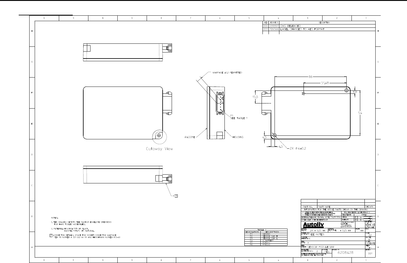
5.2.1. Dimensions and Weight of the 24 GHz Sensor
Figure 1 shows the dimensions of the 24 GHz sensor and details the mounting of
the sensor.
Please refer to Fig. 1 for the detailed drawing.
Sensor weight: 150 grams max.
Title:
Installation Specifications and User Manual, Radar Sensor, 24 GHz Doc. No. E E814702
INSTALLATION SPECIFICATION Rev. 000, Page 4 of 16
5.0 SPECIFICATIONS
Figure 1
IMPORTANT NOTE: The two mounting holes are not specified for mounting the complete sensor. They do not provide the
mechanical properties to keep the sensor in place. They shall be used to fix the sensor in a mounting bracket. Mounting tabs
are to be fastened tight to mounting bracket using appropriate fastener. Maximum strength per tab is 270 N.
Title:
Installation Specifications and User Manual, Radar
Sensor, 24 GHz Doc. No. E E814702
INSTALLATION SPECIFICATION Rev. 000, Page 5 of 16
5.0 SPECIFICATIONS
5.2 24 GHz Sensor (cont’d)
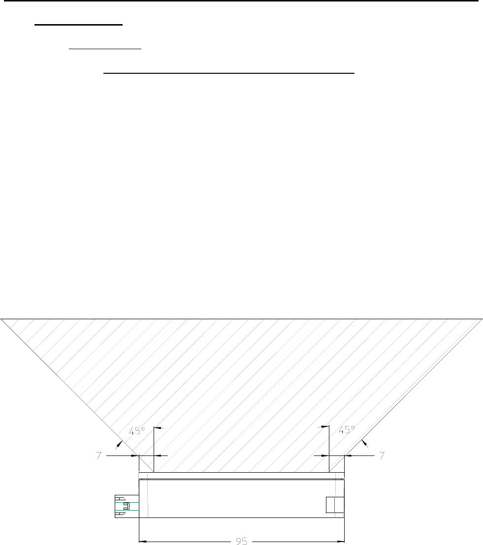
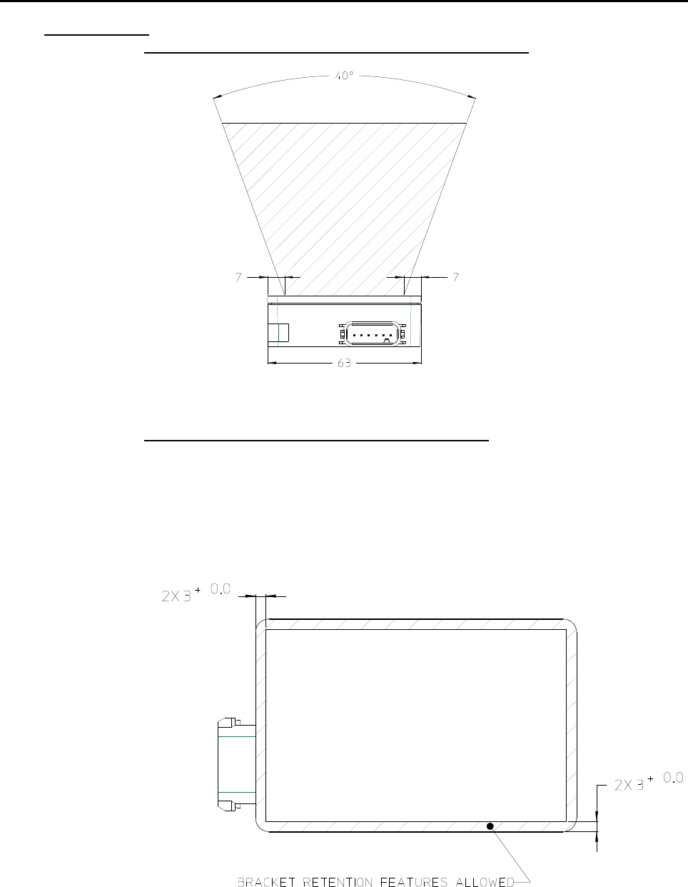
5.2.2 Keep-Out Zone / Azimuth Angle Measurement Range
Figure 2 displays the keep out area of the 24 GHz sensor.
Within the detection area of the antennas there must not be objects like screws,
mounting brackets, license plates etc. The impact reducing foam material, clips
or fascia laminations has to be avoided in that area.
Within the keep out zone of the antennas there must be no vertical character
lines present in the fascia. Mounting bracket material shall not enter the non-
conductive keep out zone. Bracket retention features which interface with the
surface of the sensor radome shall not enter the keep out zone noted in Section
5.2.5
The keep out zone in the azimuth direction is ±45°. The angle is established
7mm from the edge of the sensor.
Note: For blind spot applications the keep out zone in the azimuth direction shall
be ±65°.
Figure 2
Title:
Installation Specifications and User Manual, Radar
Sensor, 24 GHz Doc. No. E E814702
INSTALLATION SPECIFICATION Rev. 000, Page 6 of 16
5.0 SPECIFICATIONS
5.2 24 GHz Sensor (cont’d)
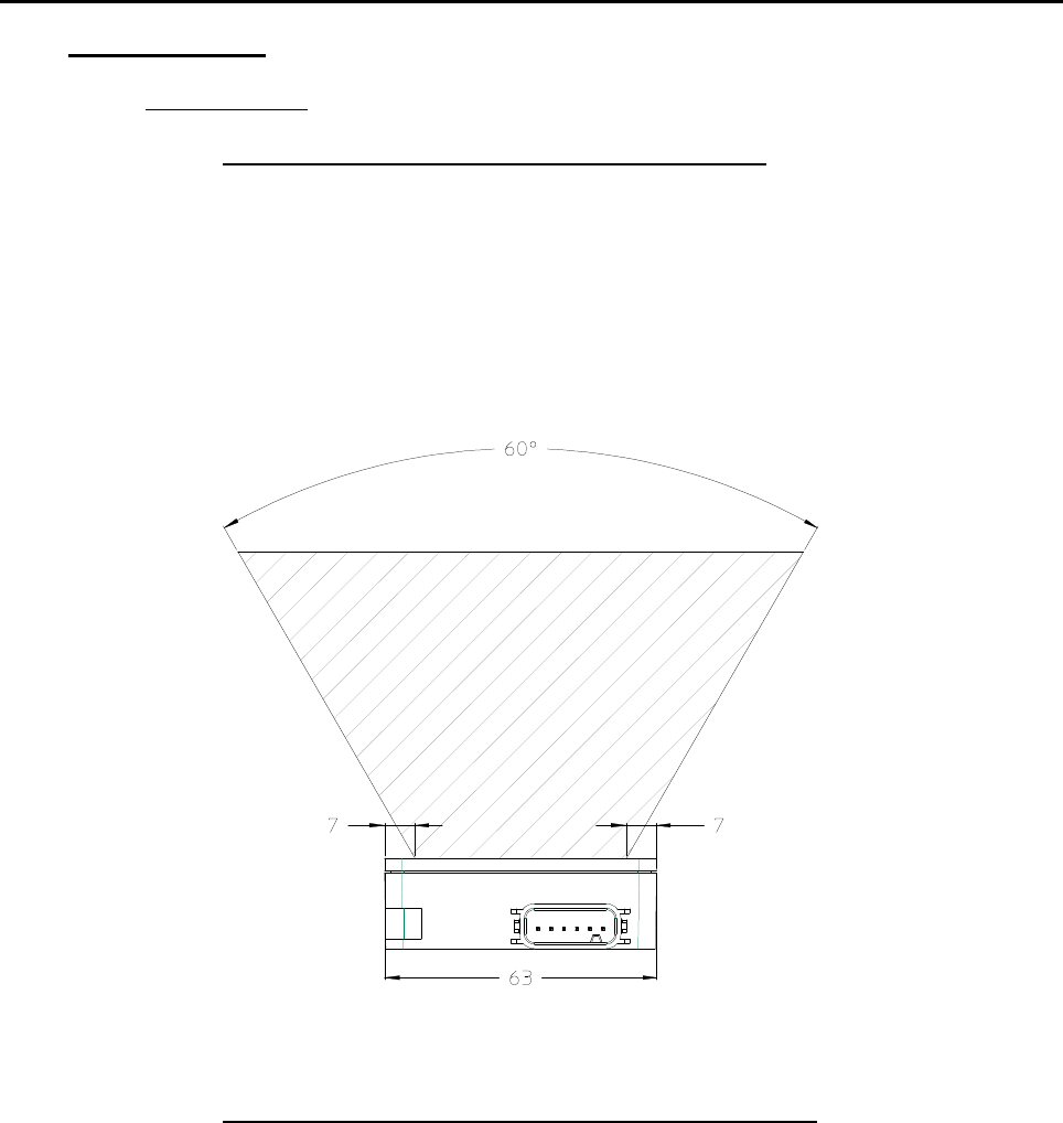
5.2.3 Conductive material keep-out zone, Angle Elevation
Figure 3
the conductive material keep out area of the 24 GHz Sensor
Within the keep out zone there must not be metal parts like screws, mounting
brackets, license plate etc. The impact reducing foam material, clips or fascia
laminations has to be avoided in that area.
This conductive material keep out zone in elevation is ±30°. This angle is
established 7mm from the edge of the sensor.
Figure 3
5.2.4 Non-Conductive material keep-out zone, Angle Elevation
Figure 3a displays the Non-Conductive keep out area of the 24GHz Sensor.
Within the non-conductive keep out zone of the antennas there must be no
vertical character lines present in the fascia. Mounting bracket material shall not
enter the non-conductive keep out zone. Bracket retention features which
interface with the surface of the sensor radome shall not enter the keep out zone
noted in Section 5.2.5
The non-conductive keep out zone in the elevation direction is ±20°. This angle
is established 7mm from the edge of the sensor.
Title:
Installation Specifications and User Manual, Radar
Sensor, 24 GHz Doc. No. E E814702
INSTALLATION SPECIFICATION Rev. 000, Page 7 of 16
5.2 24 GHz Sensor (cont’d)
5.2.4 Non-Conductive material keep-out zone, Angle Elevation (cont’d)
Figure 3a
5.2.5 Bracket to sensor retention features keep out zone
Bracket retention features which are used to hold the sensor into the bracket,
shall be made of non-conductive material, and protrude into the face of the
sensor radome with enough overlap to overcome any variability in the bracket (ie.
bracket to sensor gap, material distortion). A general guideline is to create a
retention feature with overlap which is positioned in the allowable shaded area
outlined below (Figure 3b).
Figure 3b
Title:
Installation Specifications and User Manual, Radar
Sensor, 24 GHz Doc. No. E E814702
INSTALLATION SPECIFICATION Rev. 000, Page 8 of 16
5.3 Installation Specifications for Individual Sensors
5.3.1 Distance to the Bumper Material
The distance of the 24 GHz Sensor to the bumper shall be between 5
and 20 mm. If the distance is below 5 mm a significant signal loss
occurs. If the distance is larger, error ranges may appear within the
close range.
Figure 4
5.3.2 Angle with Respect to Bumper Material
The angle ϕ of the sensor with regard to the bumper should be 0
°
,
meaning the sensor should be installed parallel to the bumper. If this is
not possible, an angle of ±10° shall not be exceede d. Other
orientations need to be tested to confirm proper operation.
Figure 5
5 – 20mm
ϕ
Title:
Installation Specifications and User Manual, Radar
Sensor, 24 GHz Doc. No. E E814702
INSTALLATION SPECIFICATION Rev. 000, Page 9 of 16
5.0 SPECIFICATIONS
5.3 Installation Specifications for Individual Sensors (cont’d)
5.3.3 Effect of Type- and Thickness of Fascia Material
Autoliv has examined various fascia material samples with a thickness
of 2.5 – 4 mm. Fascia loss effects can be optimized by proper control
of the material thickness and dielectric constant. Thickness should be
uniform in front of the radar sensor.
Thickness and dielectric constant must be controlled to a tolerance of
±10% max to ensure optimal performance.
New fascia material shall be evaluated by Autoliv for its characteristics
at RF antenna frequency.
5.3.4 Effect of the Paint
Effect of paint is detailed in Appendix A. New paint material shall be
evaluated by Autoliv.
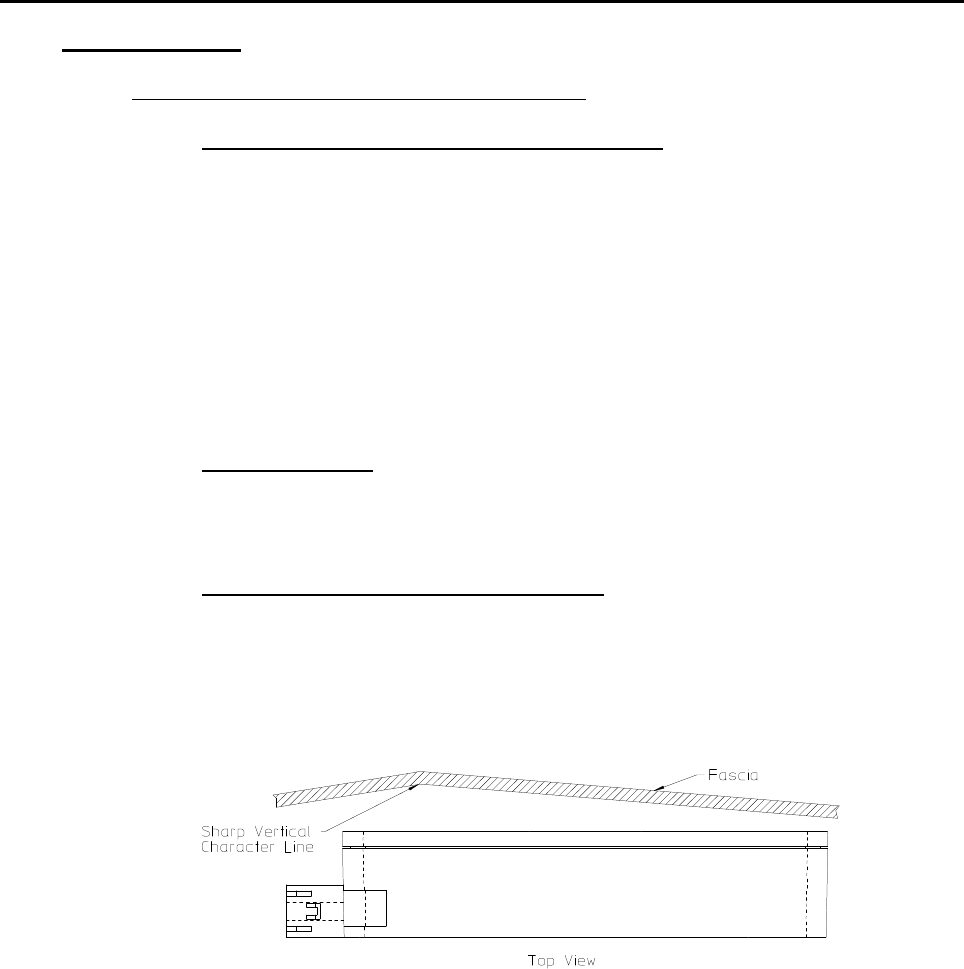
5.3.5 Smoothness of Fascia in Front of Antenna
Avoid sharp vertical or near vertical character lines in front of sensor
antenna. Horizontal character lines seem to have little effect on sensor
performance.
Figure 6
Title:
Installation Specifications and User Manual, Radar
Sensor, 24 GHz Doc. No. E E814702
INSTALLATION SPECIFICATION Rev. 000, Page 10 of 16
5.0 SPECIFICATIONS
5.3 Installation Specifications For Individual Sensors (cont’d)
5.3.6 Protection from Mud and Dirt Buildup
There will be performance degradation if excessive buildup occurs on the
antenna areas and especially for wet mud. Therefore Autoliv strongly
recommends the sensor mounting include provisions to protect the antenna face
from dirt and mud accumulation. The mounting concept should completely
protect the face of the antenna to prevent mud and dirt from entering the free
space between the sensor radome and the fascia, yet a small weep hole at the
bottom of the bracket is required to allow condensation to dissipate.
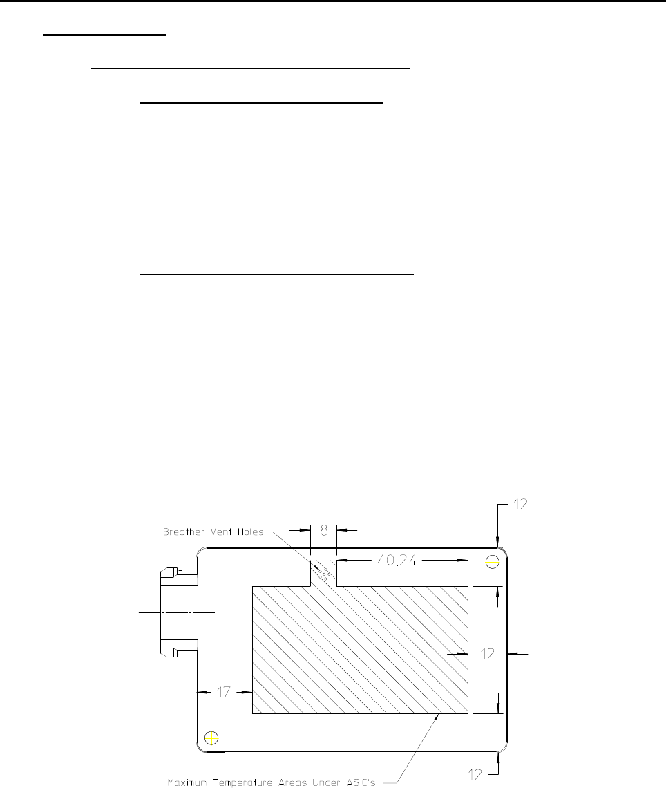
5.3.7 Sensor Mounting Thermal Considerations
The sensor is specified to operate in a –40° to +85°C ambient, still air
environment. Natural convection and venting from the front and
backside surfaces of the sensor to the ambient air is assumed.
Therefore the mounting concept shall leave both the front radome and
backside area of the sensor exposed to the ambient air. Minimum area
to be left for the backside exposed is as shown below. Bracket
reinforced structure such as cross bars are allowed if approximately
80% of backside area remains exposed to ambient air for heat
dissipation. Maximum surface temperature in this region is +115°C at a
maximum ambient of +85°C.
Figure 7
Title:
Installation Specifications and User Manual, Radar
Sensor, 24 GHz Doc. No. E E814702
INSTALLATION SPECIFICATION Rev. 000, Page 11 of 16
5.0 SPECIFICATIONS
5.3 Installation Specifications for Individual Sensors (cont’d)
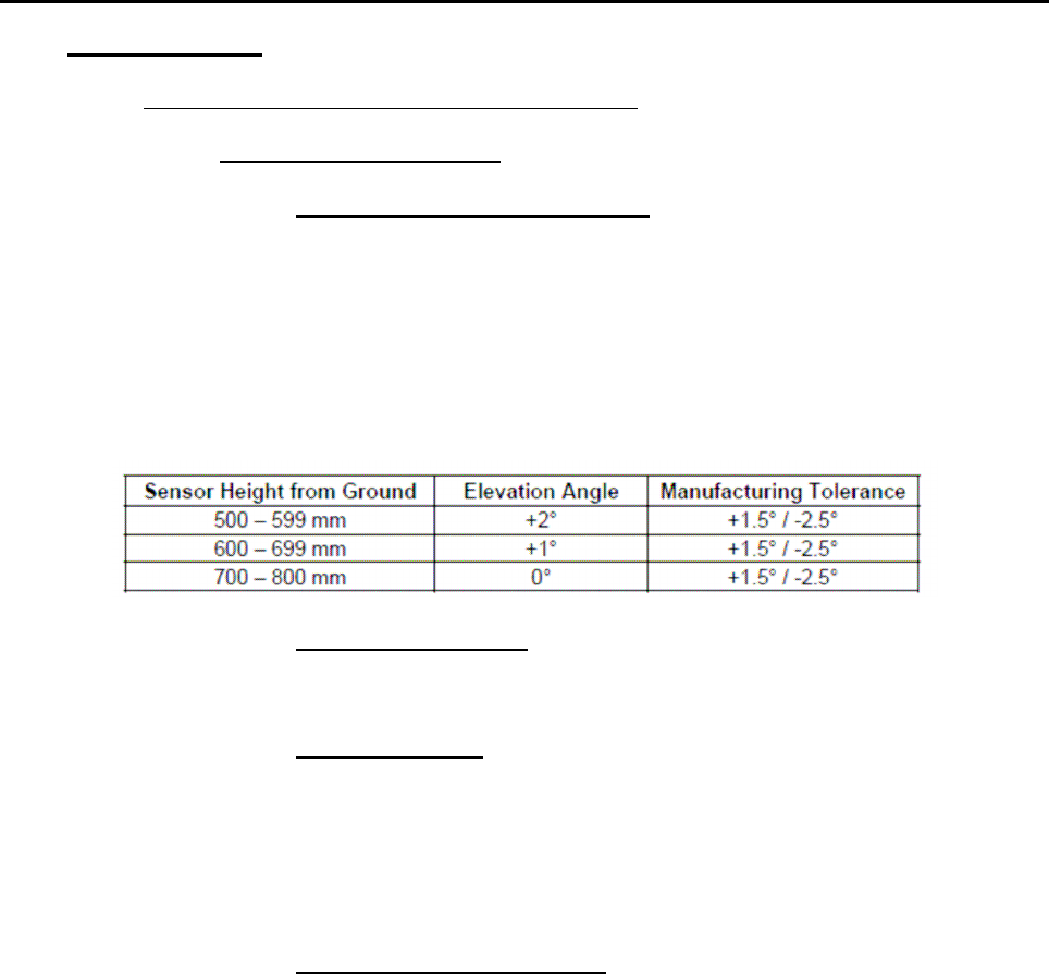
5.3.8 Side Blind Spot Application
5.3.8.1 Sensor Height vs. Elevation Angle
Please follow the following table for setting the elevation angle of the Side
Blind Spot sensor.
If packaging above 500 mm is not possible, please consult Autoliv
resident engineer to assess alternate locations.
The sensor can not be mounted below 400 mm under any circumstance.
5.3.8.2 Sensor Azimuth Angle (X-Y Plane)
Each Side Blind Spot sensor should be angled 20° re arward.
5.3.8.3 Sensor X-Position
Side Blind Spot sensor should be located as far rearward as possible
while maintaining other packaging requirements (radome to fascia B-
side, angle, etc.). For RCTA (Rear Cross Traffic Alert) application, the
maximum distance from the center of sensor to the rear of vehicle shall
not exceed 300 mm.
5.3.8.4 Sensor Connector Orientation
There is a tradeoff on sensor connector orientation that must be reviewed
with Customer. The Side Blind Spot sensor connector may be oriented
forward or rearward. If connector is facing forward, the sensor may be
positioned further rearward which is a performance benefit for the RCTA
(Rear Cross Traffic Alert) application. Also, if the connector is facing
forward, the more sensitive side of the sensor (non-connector side) will
be facing rearward - a benefit for the Side Blind Spot application.
However, it may be advised by Customer to position the sensor with
connector facing rearward due to water/salt spray concerns.
Title:
Installation Specifications and User Manual, Radar
Sensor, 24 GHz Doc. No. E E814702
INSTALLATION SPECIFICATION Rev. 000, Page 12 of 16
5.0 SPECIFICATIONS
5.3 Installation Specifications for Individual Sensors (cont’d)
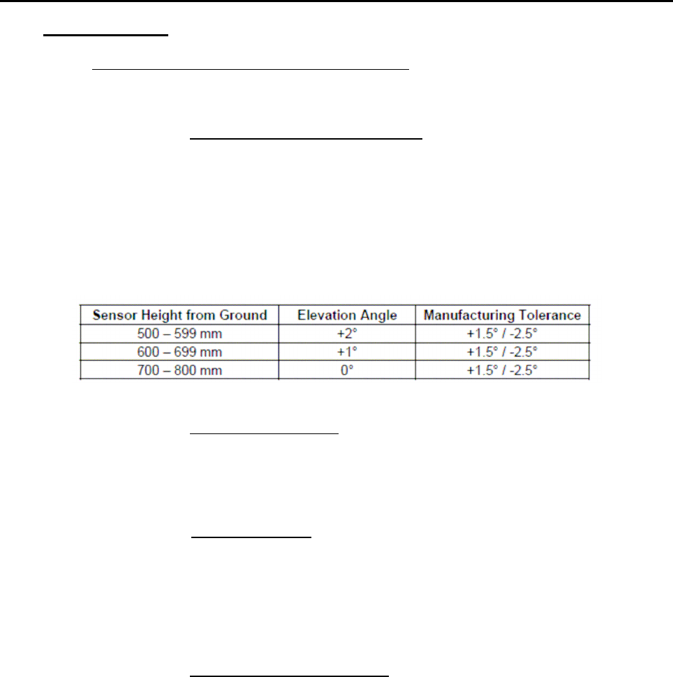
5.3.9 ESS-SRR Application
5.3.9.1 Sensor Height and Elevation Angle
Please follow the following table for setting the elevation angle of the
ESS-SRR sensor.
If packaging above 500 mm is not possible, please consult Autoliv
resident engineer to assess alternate locations.
The sensor can not be mounted below 400 mm under any circumstance,
and 500 mm is strongly recommended for vehicle rear applications.
5.3.9.2 Sensor Azimuth Angle (X-Y Plane)
Front Sensors: Azimuth Angle 4° - 7° ± 1° outboar d
Rear Sensor: Azimuth Angle 0° ± 1°
5.3.9.3 Sensor Y-Position
Front SSR sensors shall be located in the cross car position (Y direction) to
maintain adequate close range object detection at 400 mm. The 40° azimuth
angle detection cones of the two front SRR sensors shall intersect no farther
than 400 mm from the center of the fascia in order to provide adequate short
range detection for forward looking applications.
5.3.9.4 Sensor Connector Orientation
Front and rear sensors shall be positioned with the connector pointed inboard
and the distance from the fascia shall not fall below 5mm or above 20mm. This
measurement can be measured 8-10mm from the edge of the antenna.
Title:
Installation Specifications and User Manual, Radar
Sensor, 24 GHz Doc. No. E E814702
INSTALLATION SPECIFICATION Rev. 000, Page 13 of 16
6.0 24 GHZ SENSOR SYSTEM
The following observations refer to the combination of several 24 GHz Sensors into
one sensor system. Many applications require several sensors networked together to
achieve the desired function. The sensors should be placed in the best possible
location for optimal coverage and range performance relative to the specific
applications. The optimal locations will be highly dependent on the desired
applications and the bumper dimensions. Autoliv can perform analysis and
characterization to determine sensor locations to best achieve a desired performance.
Attention should be paid that the installation specifications for individual sensors from
chapter 5 are maintained. Due to the various installation situations and applications, a
measurement check is required to verify the actual installation implementation.
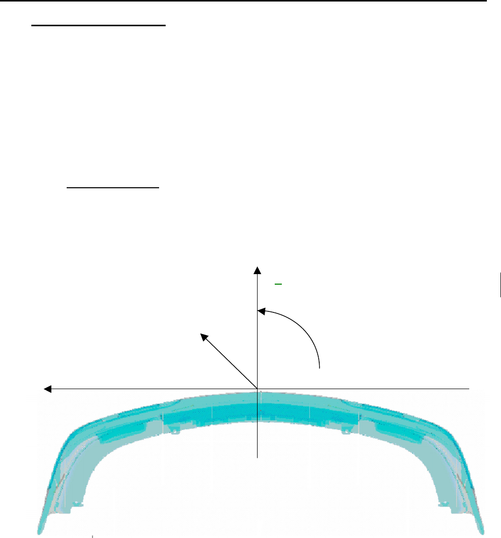
6.1. Coordinate System
Figure 8 shows the coordinate system used for identifying sensor position in a
multi-sensor application. The arrows indicate positive values. The most
forward location on the bumper was selected as reference point. The Z-axis is
the vertical axis. Z-values are indicated from the ground surface.
Figure 8
Y
Z
ϕ
ϕϕ
ϕ
X
Title:
Installation Specifications and User Manual, Radar
Sensor, 24 GHz Doc. No. E E814702
INSTALLATION SPECIFICATION Rev. 000, Page 14 of 16
6.0 24 GHZ SENSOR SYSTEM
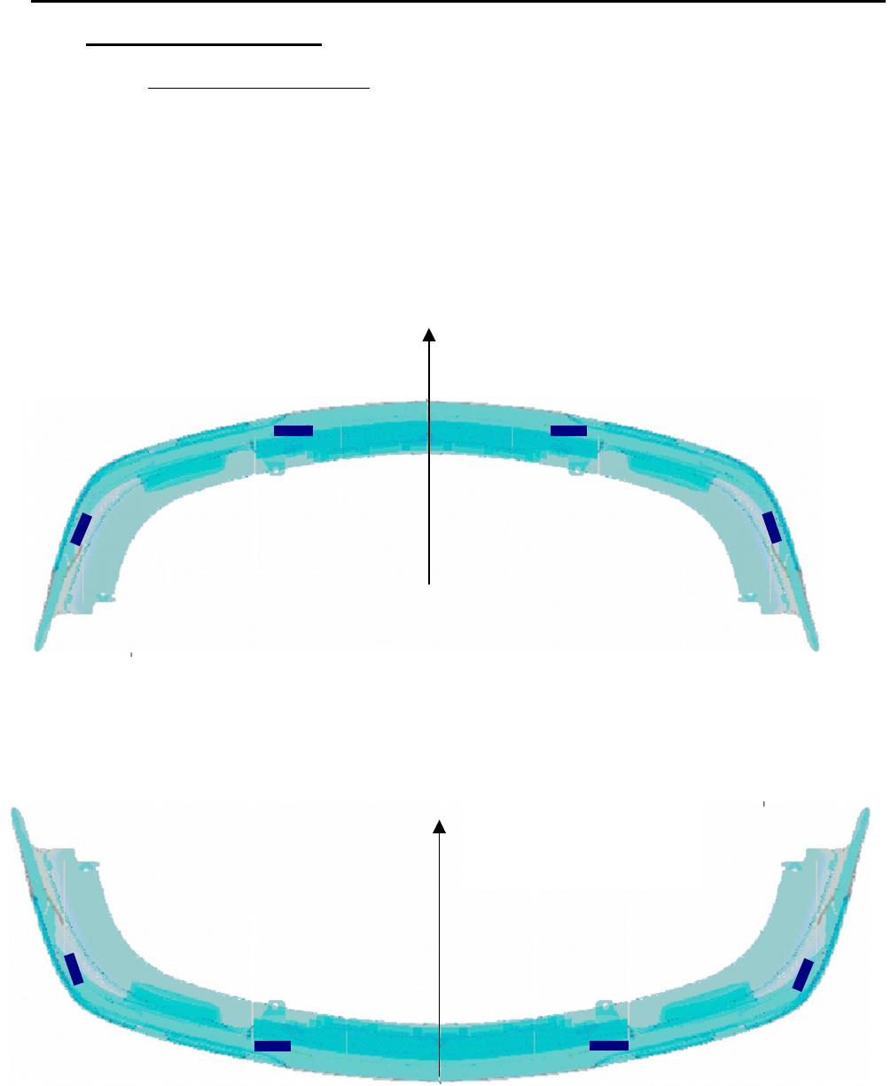
6.2. Numbering of the Sensors
The following provides a guideline for sensor numbering (addressing) in a
multi-sensor system. The example used is for a front and rear bumper system.
Each bumper contains up to 4 sensors connected on a private CAN bus. A
separate CAN bus is used for the front and rear bumpers. The sensors
transmit data over the CAN bus to a centralized processor which performs
sensor data fusion and runs the desired application.
Figure 9 shows the numbering used for a front sensor system.
Figure 9
Figure 10 shows the numbering used for a rear sensor system.
Figure 10
1F
2F
3F
4F
Driving direction
1R
2R
3R
4R
Driving direction

Title:
Installation Specifications and User Manual, Radar
Sensor, 24 GHz Doc. No. E E814702
INSTALLATION SPECIFICATION Rev. 000, Page 15 of 16
6.0 24 GHZ SENSOR SYSTEM
6.3. Installation Dimensions
6.3.1 Y-Direction
The Y location of the sensors will determine the extent of the coverage
zone and the size of any detection gaps. The location selections are
highly dependent on the desired application and bumper dimensions. In
general, for a 2 sensor longitudinal system sensors 2 &3 should be
located midway between the center of the bumper and the outer corner.
Bumper features (license plates etc.) may not allow this while
maintaining the guidelines of section 5. In this case the locations should
be as close to the ideal locations as possible while meeting the
requirements of section 5. A measurement check is required to verify
the actual installation implementation.
6.3.2 X-Direction
The X location of the sensors not as critical as Y in terms of system
performance. In general the X locations will be dictated by the contour
of the bumper and the installation guidelines of section 5.

Title:
Installation Specifications and User Manual, Radar
Sensor, 24 GHz Doc. No. E E814702
INSTALLATION SPECIFICATION Rev. 000, Page 16 of 16
APPENDIX A
EFFECT OF PAINT
Depending upon the type of paint, number of coatings, base coats used, etc. the
attenuation of the radar signal was measured between 2 and 5 dB (corresponds to
reduction of coverage between 11 and 25%). Because attenuation has significant
impact on performance, prior inspection of the material and paint samples are
suggested. Autoliv can characterize painted fascia samples to determine the radar
signal loss effects. Autoliv sensor specifications assume a maximum signal loss (2-
way) of 4 dB due to fascia effects. Materials and paints that exhibit greater than 4 dB
loss will degrade the specified performance. As noted in 5.3.3 performance can be
optimized by proper control of the fascia material thickness and dielectric constant.