Magna Electronics NB24G1V2 VEHICLE RADAR SENSOR, REAR CROSS TRAFFIC ALERT User Manual WU8NB24G1V2 UserMan
Autoliv ASP, Inc. VEHICLE RADAR SENSOR, REAR CROSS TRAFFIC ALERT WU8NB24G1V2 UserMan
User Manual

REVISION HISTORY
Rev Description Date Apprv’d
000 Initial Release 8/31/2011
001 Revised 3/15/2013
002 Certification Documentation
SENSOR MODULE,
AUTOMOTIVE RADAR, SRR, NB
FCC ID/MODEL Number: WU8NB24G1V2
TITLE: Product Description, User Manual, Installation Guideline DOCUMENT NO:
SENSOR MODULE, RADAR, SRR, NB PAGE 1 OF 16
Autoliv Electronics Lowell.
1011B Pawtucket Blvd.
Lowell, MA 01853
ATTENTION
USER OF THIS DOCUMENT IS
RESPONSIBLE FOR
DETERMINING CURRENT
REVISION LEVEL BEFORE
USING DOCUMENT.
©AUTOLIV INC. THIS DOCUMENT AND
THE DATA DISCLOSED HEREIN OR
HEREWITH IS FOR THE PURPOSE OF
CERTIFICATION DOCUMENTATION.

Product Description, User Manual, Installation Guideline Doc. No. xxxxxxxxx
SENSOR MODULE, RADAR, SRR, NB Page 2 of 16
TABLE OF CONTENTS
1.0PRODUCT OVERVIEW 4
2.0MOUNTING ORIENTATION 4
2.1.Vehicle Orientation 4
2.2.Sensor Orientation 4
3.0SPECIFICATION 5
3.1.Sensor characteristics 5
4.0BLOCK DIAGRAM 6
5.0MECHANICAL 7
5.1.Envelope dimensions, weight and connector pin-out 7
5.2.Security protection – Tamper proof features 8
5.3.Label 8
6.0INTEGRATION AND MOUNTING GUIDELINES 9
6.1.Attachment to the vehicle 9
6.2.Detection Range / Azimuth Angle Measurement Range 9
6.3.Detection Angle Elevation 10
6.4.Installation Guidelines For Individual Sensors 11
6.4.1Distance to bumper fascia 11
6.4.2Effect Of Type- And Thickness Of Fascia Material 12
6.4.3Effect of the paint 12
6.4.4Smoothness of Fascia in Front of Antenna 12
6.5.Feature installation guidelines 13
6.5.1Sensor Connector Orientation 13
6.5.2Vehicle Coordinate System 13
6.5.3Identifying the Sensor Position 13
6.5.4Y-direction recommendation 14
6.5.5X-direction recommendation 14
6.5.1Sensor Azimuth Angle (X-Y Plane) 14
6.5.2Elevation Angle recommendation 14
6.5.1Sensor Height and Elevation Angle Settings 15
7.0User information and Conformity to regulation 15
7.1.Required notice to the user in the USA for Part 15 Devices per FCC 15
7.2.Required notice to user in Canada per RSS-gen issue 3 15
7.3.Required notices to user in Japan 16

Product Description, User Manual, Installation Guideline Doc. No. xxxxxxxxx
SENSOR MODULE, RADAR, SRR, NB Page 3 of 16
LIST OF FIGURES
Figure 1. Vehicle Orientation 4
Figure 2 : Radar Orientation 4
Figure 3 : Block Diagram 6
Figure 4 : Envelope Drawing 7
Figure 5 : Label Drawing 8
Figure 6 : Bracket Retention Features 9
Figure 7 : Azimuth Detection zone 10
Figure 8 : Azimuth keep out zone 10
Figure 9 : Elevation keep out zone 11
Figure 10 : Azimuth and Elevation Keep out zones 11
Figure 11 : Distance to bumper fascia 11
Figure 12 : Character lines 12
Figure 13 : Vehicle coordinate system 13
Figure 14 : Sensor position 14
Product Description, User Manual, Installation Guideline Doc. No. xxxxxxxxx
SENSOR MODULE, RADAR, SRR, NB Page 4 of 16
1.0 PRODUCT OVERVIEW
This system is designed to provide the Blind Spot Detection, Lane Change Assist and Rear Cross
Traffic warning features as defined by the ISO17387. It relies on two standalone 24GHz narrow band
radar sensors located in the rear corners of the vehicle. This radar complies with the low power 24 GHz
narrow band regulations (also known as low power non-specific short range or “ISM”) of most countries
such as European CEPT community, USA, Canada, China, Brazil and Japan.
The sensor has two modes of operations: It operates in a Blind Spot Detection & Lane Change Assist
mode when the vehicle is in forward gear or standstill and switches to a Rear Cross Traffic Alert mode
when the vehicle is operating in reverse. The sensor generates three different waveforms. Blind Spot
Detection is optimized for very near range detection (sub 10m), Lane Change Assist is optimized for
mid-range up (70m) and Rear Cross Traffic Alert is optimized for short range detection (40m).
2.0 MOUNTING ORIENTATION
2.1. Vehicle Orientation
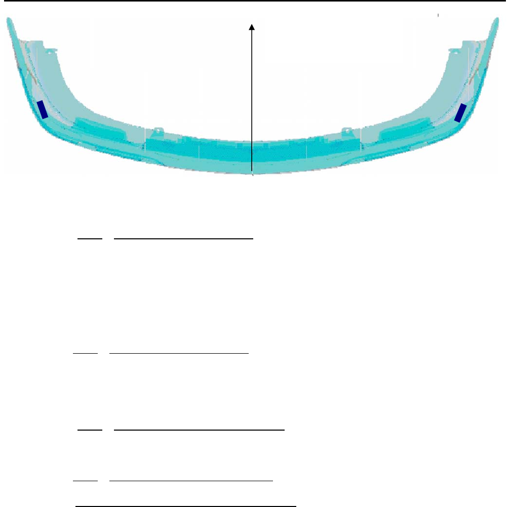
The sensor is mounted behind a plastic fascia squinted 50deg towards the rear.
Figure 1. Vehicle Orientation
2.2. Sensor Orientation
The connector must be facing towards the rear of the vehicle and the sensor boresight is facing the
fascia outwards.
Figure 2 : Radar Orientation
0 deg bore-sight
Horizontal/Azimuth 0deg UP
Vertical
50deg
Forward

Product Description, User Manual, Installation Guideline Doc. No. xxxxxxxxx
SENSOR MODULE, RADAR, SRR, NB Page 5 of 16
3.0 SPECIFICATION
3.1. Sensor characteristics
Limits Comments
External interface
OperatingTemperature‐40Cto+85CExternalAmbienttemperature
InputVoltage,operating6.0‐16.0VDC
Inputcurrent(/power)0.350AmaxI*V~constant@<4W
OperatingLife15yrs.Automotivestandard
VehiclenetworkinterfaceCAN2.0BAutomotivestandard
Digital
DSPProcessorClock(s)30.0MHz+/‐100ppmInternalPLLto150MHz
HostProcessor30.0MHz+/‐100ppmInternalPLLto60Mhz
CANbaudrate25kbpsto1MbpsCombaudrateisSWconfigurable
LEDDrivecurrent40‐60mAShort‐circuitcurrentlimited(<120mA)
RF in BSD mode
OccupiedBandwidth24.150‐24.250GHz(ISM)SeeTypeApprovalRadiotestreport
PowerOutput,Transmit+13dBmpeakinanydirection
Txpatterns–elevation+/‐11degAt‐6dBpoints
‐azimuth>‐40to+40degrees
Searchrange0.5m–14m
RangeAccuracy+/‐20cm
AngleAccuracy+/‐5degWithin+/‐40degFOV
SpeedAccuracy+/‐5km/hr
RF in LCA mode
OccupiedBandwidth24.050‐24.250GHz(ISM)SeeTypeApprovalRadiotestreport
PowerOutput,Transmit+15dBmpeakpulseinanydirection
Txpatterns–elevation+/‐11degAt‐6dBpoints
‐azimuth>‐40to+40degrees
Searchrange4m–80m
RangeAccuracy+/‐50cm
AngleAccuracy+/‐2deg
SpeedAccuracy+/‐2km/hr
RF in RCTA mode
OccupiedBandwidth24.050‐24.250GHz(ISM)SeeTypeApprovalRadiotestreport
PowerOutput,Transmit+15dBmpeakpulseinanydirection
Txpatterns–elevation+/‐10degAt‐6dBpoints
‐azimuth>‐40to+40degrees
Searchrange2m–60m
RangeAccuracy+/‐50cm
AngleAccuracy+/‐5deg
SpeedAccuracy+/‐2km/h
Antenna Polarization LinearVertical
RF Oscillator 60MHz+/‐100ppm
Table 1, Performance Characteristics
Product Description, User Manual, Installation Guideline Doc. No. xxxxxxxxx
SENSOR MODULE, RADAR, SRR, NB Page 7 of 16
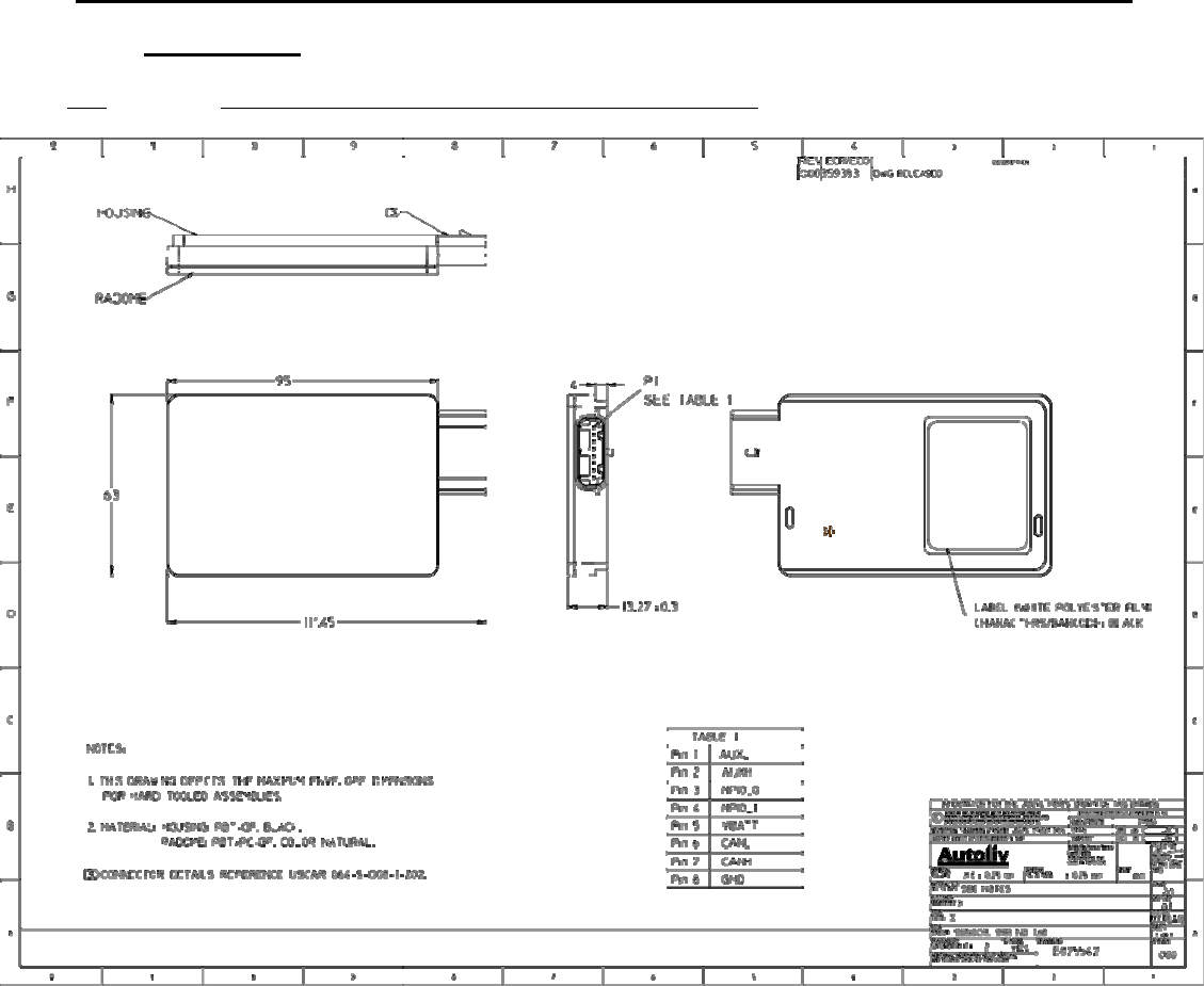
5.0 MECHANICAL
5.1. Envelope dimensions, weight and connector pin-out
Figure 4 : Envelope Drawing
Product Description, User Manual, Installation Guideline Doc. No. xxxxxxxxx
SENSOR MODULE, RADAR, SRR, NB Page 8 of 16
Sensor Weight: 90 grams approx.
5.2. Security protection – Tamper proof features
Sensor is sealed by LASER Welding the cover with the plastic housing during manufacturing and
cannot be disassembled without permanent and visible damages to the structure. The sensor has no
serviceable parts and therefore is not repairable.
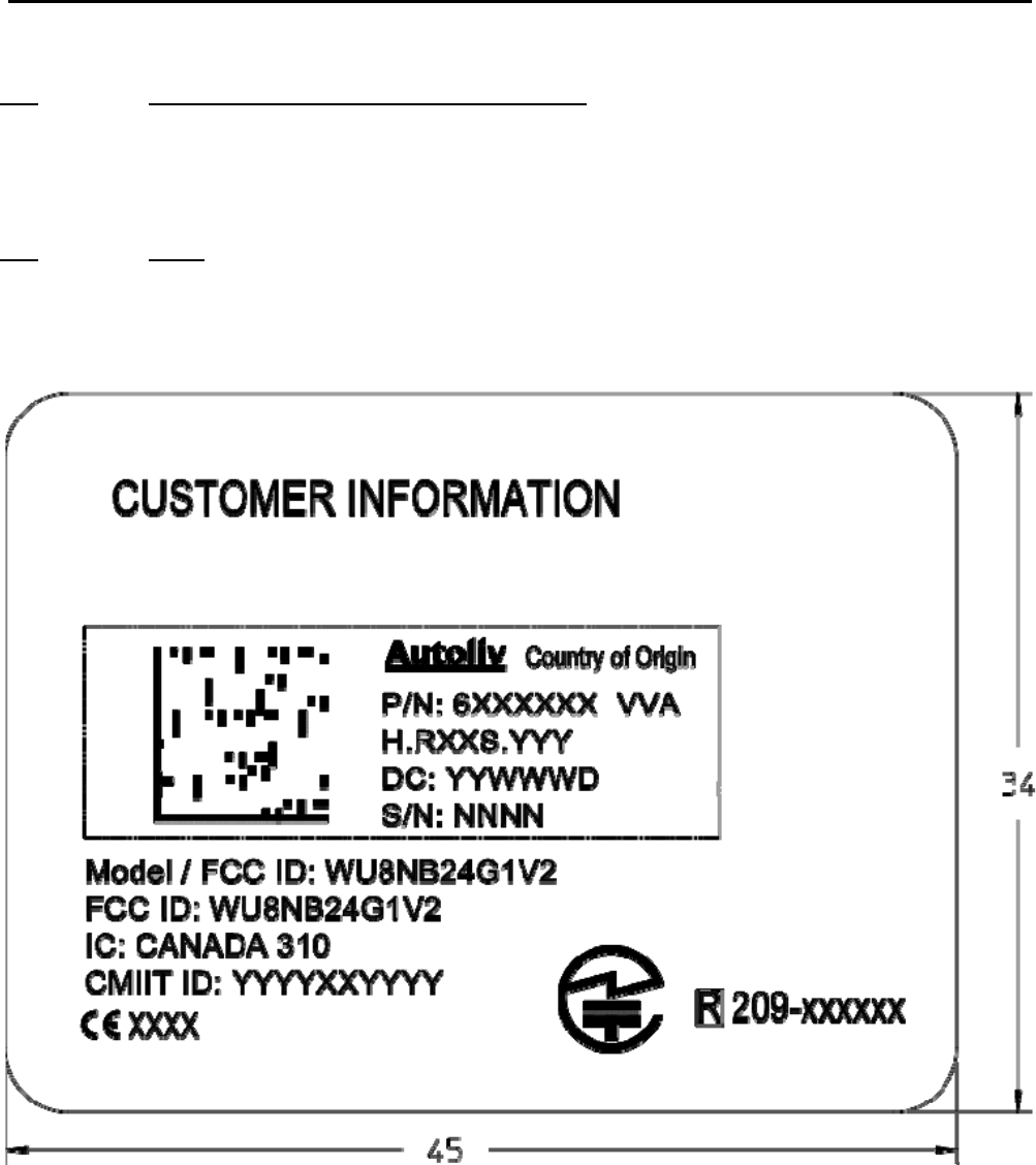
5.3. Label
Find below the drawing of the label for part traceability and type approval markings. The label is
attached to the back of the sensor per the drawing in Figure 5. Dimensions are in mm.
Figure 5 : Label Drawing
Product Description, User Manual, Installation Guideline Doc. No. xxxxxxxxx
SENSOR MODULE, RADAR, SRR, NB Page 9 of 16
6.0 INTEGRATION AND MOUNTING GUIDELINES
This chapter describes the characteristics relevant to the installation of NB-SRR sensors in the bumper.
In addition general specifications are mentioned, which have to be followed for each position to enable
sufficient sensor performance. Therefore the following guidelines are to be observed carefully.
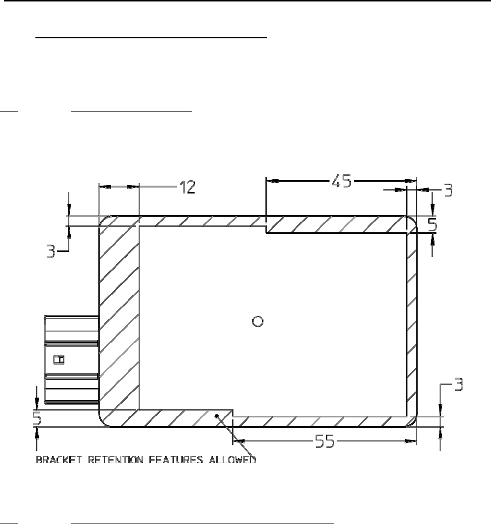
6.1. Attachment to the vehicle
The sensor slides in a plastic bracket. The bracket is attached either to the vehicle chassis structure or
directly to the plastic fascia of the vehicle. The connector must face towards the rear of the vehicle to
ensure the performance characteristics listed in Table 1.
Figure 6 : Bracket Retention Features
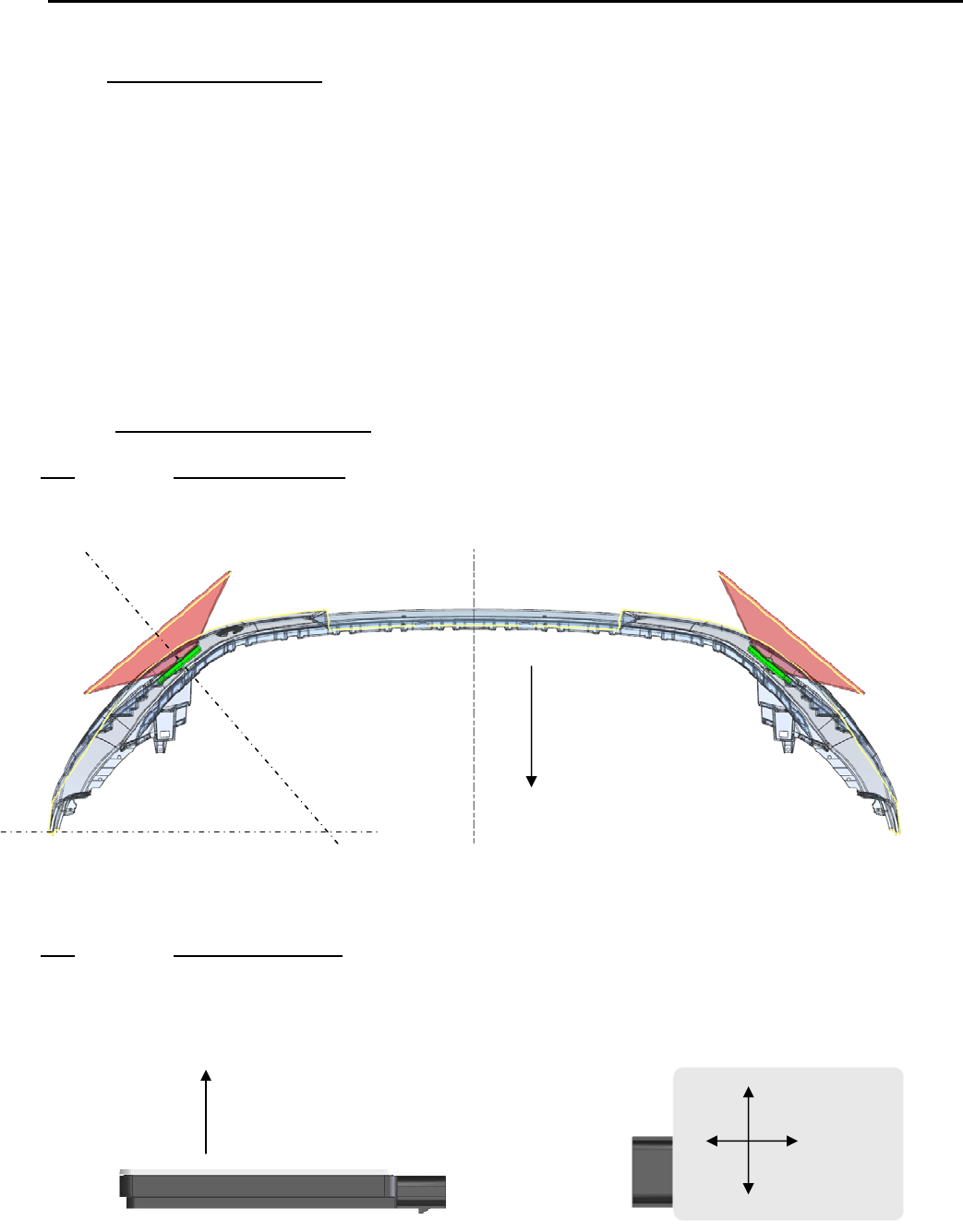
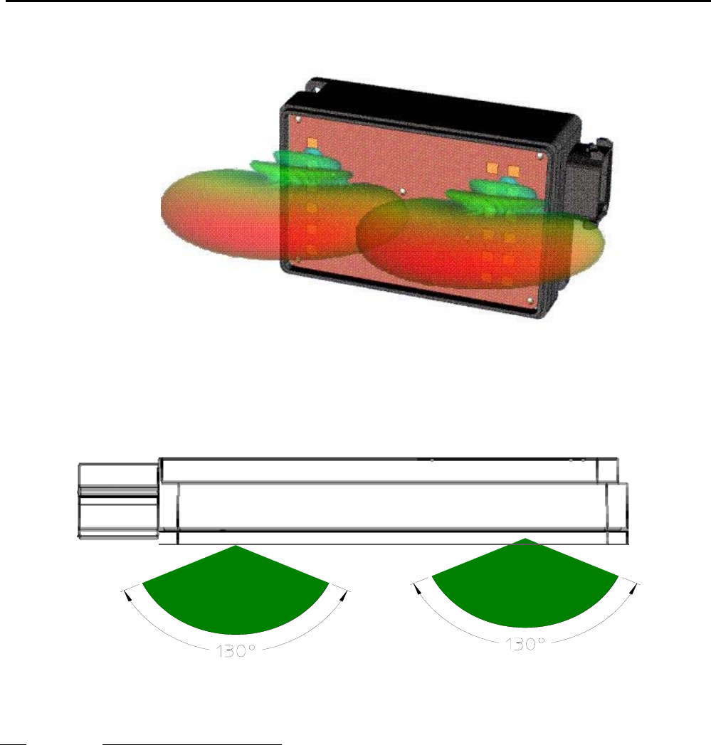
6.2. Detection Range / Azimuth Angle Measurement Range
Figure 8 displays the detection area of the NB-SRR sensor. One should differentiate between the
detection area of the sensor and the angle measurement area. The angle measurement area is
reduced to ±50° around bore sight whereas the detection area is as wide as ±65° in azimuth. Within the
detection area of the antennas there must not be metal parts like screws, mounting brackets, license
plate etc. The impact reducing foam material, clips or fascia laminations has to be avoided in that area.
The azimuth keep out zone is shown in Figure 9. If the azimuth keep out zone is not followed, then the
performance of the sensor will be degraded. Consult Autoliv for guidance if the azimuth keep out zone
is violated.
Product Description, User Manual, Installation Guideline Doc. No. xxxxxxxxx
SENSOR MODULE, RADAR, SRR, NB Page 10 of 16
Figure 7 : Azimuth Detection zone
Figure 8 : Azimuth keep out zone
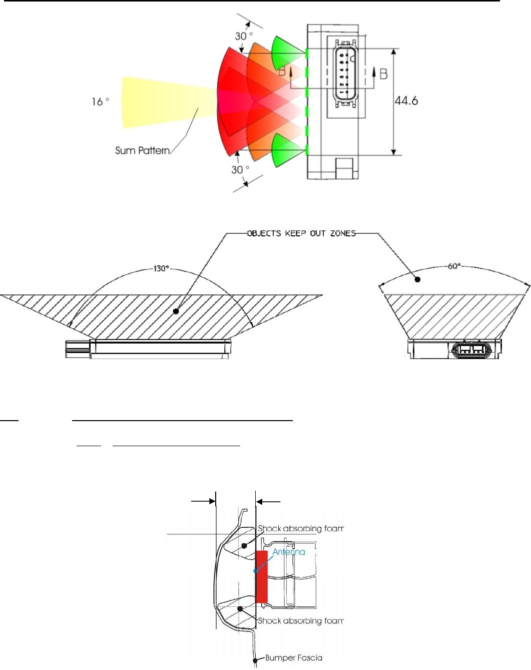
6.3. Detection Angle Elevation
The detection angle of ±10° is related to the 3dB points of the elevation transmit pattern; this means the
area where the signal amplitude is reduced by 3dB compared to bore sight direction. To avoid close
range false objects there must not be metal parts like screws, mounting brackets, license plate, etc. in
an angle of ±30° (see figure 10). Impact reducing foam material, clips or fascia laminations must be
avoided in this area.
Figure 11 shows details of objects keep out zone for both azimuth and elevation.
Product Description, User Manual, Installation Guideline Doc. No. xxxxxxxxx
SENSOR MODULE, RADAR, SRR, NB Page 11 of 16
Figure 9 : Elevation keep out zone
Figure 10 : Azimuth and Elevation Keep out zones
6.4. Installation Guidelines For Individual Sensors
6.4.1 Distance to bumper fascia
The distance of the NB-SRR sensor to the bumper shall be between 5 and 20 mm in front of the
antennas.
Figure 11 : Distance to bumper fascia
5 – 20mm
Product Description, User Manual, Installation Guideline Doc. No. xxxxxxxxx
SENSOR MODULE, RADAR, SRR, NB Page 12 of 16
6.4.2 Effect Of Type- And Thickness Of Fascia Material
Autoliv has examined various fascia material samples with a thickness of 2.5 – 4 mm. For those
samples, the radar signal is attenuated by 0.5 – 2 dB (corresponds to reduction of the range of
coverage of 2 – 11%). Impact reducing material (foam) causes additional attenuation, especially when
water is absorbed. Therefore, there shall be no impact reducing material in the antenna areas as
described in 6.2 – 6.3. There shall also be no metallic parts, snap-on contacts, clips or double wall
laminations in the antenna areas as described in 6.2 – 6.3.
Fascia loss effects can be minimized by proper control of the material thickness and dielectric constant.
Autoliv recommends the analysis of sample materials to determine the dielectric constant and proper
thickness for optimal performance. Thickness and dielectric constant must be controlled to a tolerance
of ±10% max to ensure optimal performance. Please consult Autoliv with prospective fascia
configurations to assess potential performance impacts.
6.4.3 Effect of the paint
Depending upon the type of paint, number of coatings, base coats used, etc., the attenuation of the
radar signal due to the paint varies roughly between 2 and 5 dB (corresponds to reduction of coverage
between 11 and 25%). Because attenuation has significant impact on performance, prior inspection of
the material and paint samples are suggested.
Autoliv recommends the characterization of painted fascia samples to determine the radar signal loss
effects. Autoliv sensor specifications assume a maximum signal loss (2-way) of 4 dB due to fascia
effects. Materials and paints that exhibit greater than 4 dB loss will degrade the specified performance.
As noted in 6.4.2 performance can be optimized by proper control of the fascia material thickness and
dielectric constant.
New fascia, paint material or process by the OEM should be submitted to Autoliv for characterization.
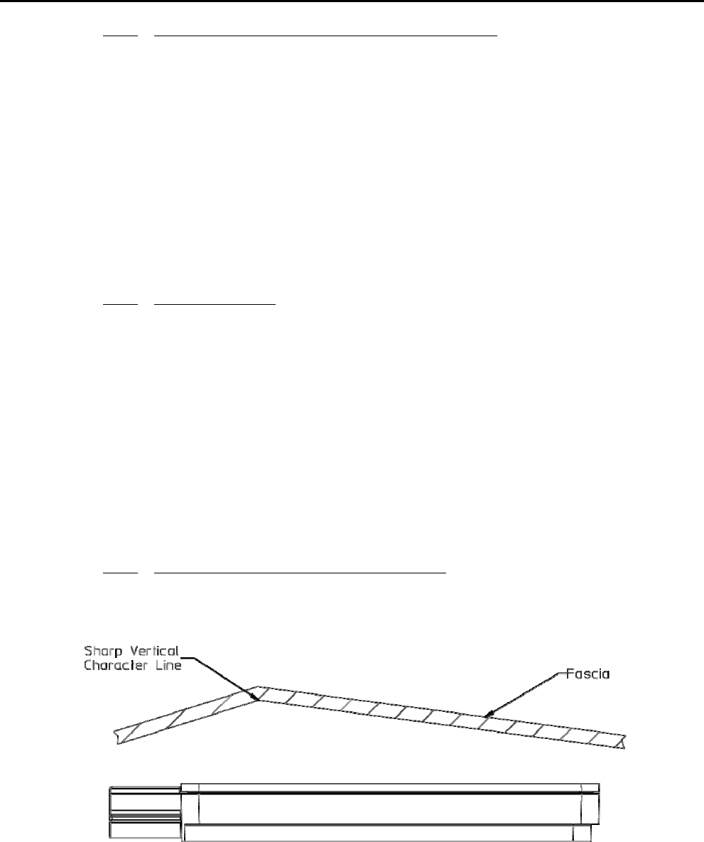
6.4.4 Smoothness of Fascia in Front of Antenna
Avoid sharp vertical or horizontal character lines in front of sensor antenna. Horizontal character lines
have less of an effect on sensor performance.
Figure 12 : Character lines
Product Description, User Manual, Installation Guideline Doc. No. xxxxxxxxx
SENSOR MODULE, RADAR, SRR, NB Page 13 of 16
6.5. Feature installation guidelines
The sensors should be located in the optimal location for best overall coverage and range performance.
The optimal locations will be dependent upon the specific application and the bumper characteristics.
6.5.1 Sensor Connector Orientation
The Sensor connector orientation must be oriented rearward.
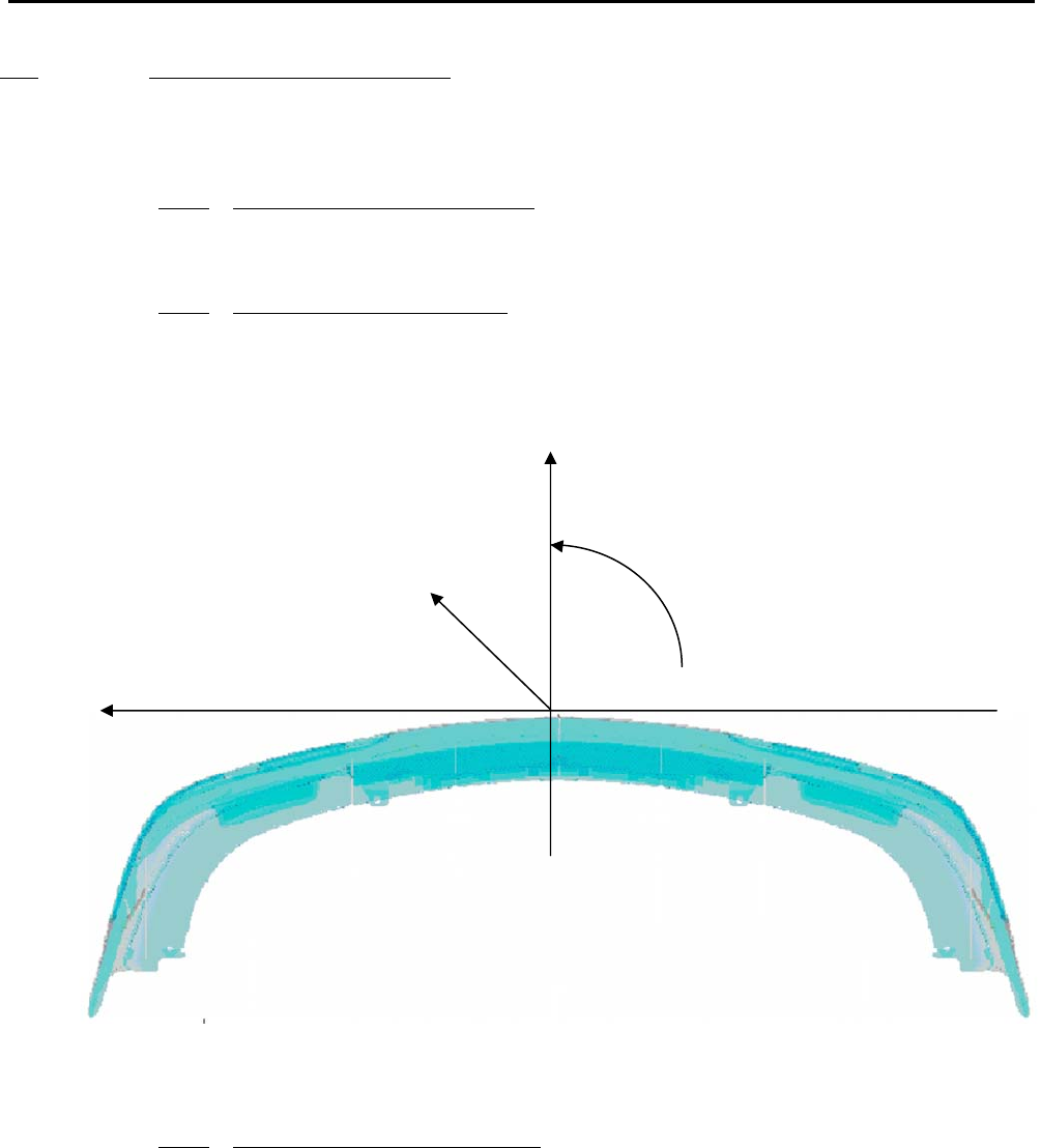
6.5.2 Vehicle Coordinate System
Figure 8 shows the coordinate system used for identifying sensor position in a multi-sensor application.
The arrows indicate positive values. The most forward location on the front bumper was selected as
reference point. The Z-axis is the vertical axis. Z-values are indicated from the ground surface.
Figure 13 : Vehicle coordinate system
6.5.3 Identifying the Sensor Position
Figure 16 represents typical positions for REAR mounted Sensors on a vehicle bumper.
The left and right sensors are inter-changeable and the sensors have an addressable pin in the
vehicle connector that is used to logically identify the sensors position to the system. A
GROUND or OPEN connection from the vehicle harness to this particular contact pin dictates the
Sensor’s position on the vehicle to the system. The address pin of the right sensor must be
grounded while the address pin of the left sensor must remain unconnected.
Y
Z
ϕ
X
Product Description, User Manual, Installation Guideline Doc. No. xxxxxxxxx
SENSOR MODULE, RADAR, SRR, NB Page 14 of 16
Figure 14 : Sensor position
6.5.4 Y-direction recommendation
The Y location of the sensors will determine the extent of the rear side Blind zone coverage. The
location selections are highly dependent on the desired application and bumper dimensions. Bumper
features (chrome trim, badges, etc.) may not allow this while maintaining the guidelines of section 5. In
this case the locations should be as close to the ideal locations as possible while meeting the
requirements of section 5. A measurement check is required to verify the actual installation
implementation.
6.5.5 X-direction recommendation
In general, the X locations will be dictated by the contour of the bumper and the installation guidelines
of section 5. However, each sensor should be located as far rearward as possible while maintaining
other packaging requirements (radome to fascia B-side, angle, etc.).
6.5.1 Sensor Azimuth Angle (X-Y Plane)
Each sensor shall be angled 50° +/-1deg rearward.
6.5.2 Elevation Angle recommendation
Preferably, the elevation angle of the sensors shall be 0 deg [+1° / -1°] with respect to the ground
(sensor white cover surface perpendicular (90°) to the ground).
Right
Left
Driving direction
Product Description, User Manual, Installation Guideline Doc. No. xxxxxxxxx
SENSOR MODULE, RADAR, SRR, NB Page 15 of 16
6.5.1 Sensor Height and Elevation Angle Settings
Please follow the following table for setting the elevation angle of the Side Blind Spot / Lane change
Assist sensor. The sensor shall not be placed below 500mm or above 600mm without review and
approval by Autoliv.
Sensor Height from Ground Elevation Angle Manufacturing Tolerance
550 – 650 mm 0° +1° / -1°
7.0 User information and Conformity to regulation
7.1. Required notice to the user in the USA for Part 15 Devices per FCC
This device complies with part 15 of the FCC Rules and is identified as WU8NB24G1V2.
Operation is subject to the following conditions:
1. This device must not cause harmful interference, and
2. This device must accept any interference received, including interference that may cause undesired
operation.
Changes and Modifications not expressly approved by AUTOLIV can void your authority to operate this
equipment under Federal Communications Commission’s rules.
RADIO AND TELEVISION INTERFERENCE
NOTE: This equipment has been tested and found to comply with the limits for a Class A
digital device, pursuant to Part 15 of the FCC rules. These limits are designed to provide
reasonable protection against harmful interference when the equipment is operated in a
commercial environment. This equipment generates, uses and can radiate radio
frequency energy and, if not installed and used in accordance with the instruction
manual, may cause harmful interference to radio communications. Operation of this
equipment in a residential area is likely to cause harmful interference in which case the
user will be required to correct the interference at his own expense.
7.2. Required notice to user in Canada per RSS-gen issue 3
This device complies with Industry Canada license-exempt RSS standard(s) and is identified with the
marking IC CANADA 310.
Operation is subject to the following two conditions: (1) this device may not cause interference, and (2)
this device must accept any interference, including interference that may cause undesired operation of
the device.
Le présent appareil est conforme aux CNR d'Industrie Canada applicables aux appareils radio exempts
de licence. L'exploitation est autorisée aux deux conditions suivantes : (1) l'appareil ne doit pas
produire de brouillage, et (2) l'utilisateur de l'appareil doit accepter tout brouillage radioélectrique subi,
même si le brouillage est susceptible d'en compromettre le fonctionnement.

Product Description, User Manual, Installation Guideline Doc. No. xxxxxxxxx
SENSOR MODULE, RADAR, SRR, NB Page 16 of 16
7.3. Required notices to user in Japan
This device has been granted a designation number by the Ministry of Internal Affairs and
Communications according to the Ordinance concerning the Technical Regulations
Conformity Certification etc. of Specified Radio Equipment (特定無線設備の技術基準適合証明等に関す
る規則) Article 2 clause 1 item 8 Approval n°: 202-SMAO32
This device shall not be modified otherwise the granted designation number will become invalid.