Magna Electronics SRSC5 24 GHz Ultra Wideband Sensor C5 User Manual E567781 001
Autoliv ASP, Inc. 24 GHz Ultra Wideband Sensor C5 E567781 001
Contents
- 1. 06 Users Manual Preliminary
- 2. 06 Installation Manual
06 Installation Manual

REVISION HISTORY
Rev Description Date Apprv’d
000 Initial Release per ECO 066734 Ref. PLM
001 Added “and User Manual” to title and
added para to section 7.1. SP Ref. PLM
TITLE: Installation Specifications and User Manual,Radar
Sensor DOCUMENT NO: E567781
INSTALLATION SPECIFICATION REV. 001, PAGE 1 OF 14
AEL, Inc.
1011B Pawtucket Blvd.
Lowell, MA 01853
ATTENTION
USER OF THIS DOCUMENT IS
RESPONSIBLE FOR
DETERMINING CURRENT
REVISION LEVEL BEFORE
USING DOCUMENT.
©AUTOLIV INC. THIS DOCUMENT AND
THE DATA DISCLOSED HEREIN OR
HEREWITH IS PROPRIETARY AND MAY
NOT BE REPRODUCED, USED OR
DISCLOSED IN WHOLE OR IN PART
WITHOUT WRITTEN PERMISSION
FROM AUTOLIV INC.

Title: Installation Specifications and User Manual, Radar
Sensors Doc. No. E567781
INSTALLATION SPECIFICATION Rev. 001, Page 2 of 14
TABLE OF CONTENTS
1.0 PURPOSE/SCOPE 3
2.0 MATERIALS/EQUIPMENT 3
3.0 APPLICABLE DOCUMENTS 3
4.0 DEFINITIONS 3
5.0 SPECIFICATIONS 3
5.1. Preface 3
5.2. SLR Sensor 3
5.2.1. Dimensions and Weight of the SLR Sensor 3
5.0 SPECIFICATIONS 4
5.2.2 Detection Range / Azimuth Angle Measurement Range 5
5.2.3 Detection Angle Elevation 6
5.3.1 Distance To The Bumper Material 7
5.3.2 Angle with respect to bumper material 7
5.3.3 Effect Of Type- And Thickness Of Fascia Material 8
5.3.4 Effect of the paint 8
5.3.5 Smoothness of Fascia in Front of Antenna 8
5.3.6 Environmental Conditions 9
5.3.7 Protection From Mud And Dirt Buildup 10
5.3.8 Sensor mounting thermal considerations 10
6.0 SLR SENSOR SYSTEM 11
6.1. Coordinate System 11
6.2. Numbering of the Sensors 12
6.3. Installation Dimensions 13
6.3.1 Y-direction 13
6.3.2 X-direction 13
6.3.3 Azimuth angle 13
6.3.4 Elevation Angle 13
7.0 APPENDIX 14
7.1. Range Performance vs Attenuation 14
LIST OF FIGURES
Figure 1 4
Figure 2 5
Figure 3 6
Figure 4 6
Figure 5 7
Figure 6 7
Figure 7 10
Figure 8 11
Figure 9 12
Figure 10 12
Figure 11 14

Title: Installation Specifications and User Manual, Radar
Sensors Doc. No. E567781
INSTALLATION SPECIFICATION Rev. 001, Page 3 of 14
1.0 PURPOSE/SCOPE
This document describes the specifications for installation of type SLR Radar Sensors.
2.0 MATERIALS/EQUIPMENT
N/A
3.0 APPLICABLE DOCUMENTS
Outline 6181175
DIN 40050-9 IP6K9K
IEC 68-2-6 Fc IEC 68-2-7 IEC68-2-10 IEC68-2-11 Ka
IEC 668-2-14Nb IEC 68-2-27 IEC 68-2-29 IEC68-2-30
IEC68-2-32 IEC68-2-38 IEC68-2-50 IEC68-2-51
IEC68-2-52 IEC68-2-56 IEC68-2-64Fh IEC529, 13.4
SAE J1211 SAE J1812 SAE J1879
4.0 DEFINITIONS
N/A
5.0 SPECIFICATIONS
5.1. Preface
This chapter describes the specifications to install short range SLR radar into bumpers.
These specifications shall be complied with to enable the specified characteristics of the
sensors as well as the complete system. Due to the various installation situations and
applications, a measurement check is required to verify the actual installation
implementation.
5.2. SLR Sensor
This chapter describes the characteristics relevant to the installation of SLR sensors in
the bumper. In addition general specifications are mentioned, which have to be followed
for each position to enable sufficient sensor performance. Therefore the following
guidelines are to be observed very carefully. See annex for performance
measurements.
5.2.1. Dimensions and Weight of the SLR Sensor
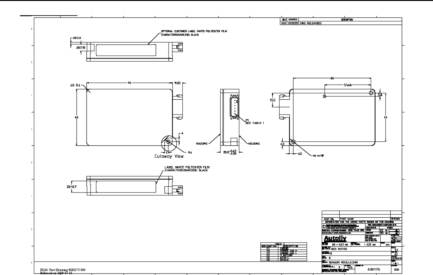
Figure 1 shows the dimensions of the SLR sensor (C-sample status) and details
the mounting of the sensor.
Please refer to “Outline 6181175” for detailed drawings.
Sensor weight: 190 grams max.
Title: Installation Specifications and User Manual, Radar Sensors Doc. No. E567781
INSTALLATION SPECIFICATION Rev. 001, Page 4 of 14
5.0 SPECIFICATIONS
Figure 1
Important note: The two mounting holes are not specified for mounting the complete sensor. They do not provide the mechanical
properties to keep the sensor in place. They shall be used to fix the sensor in a mounting bracket. Mounting tabs are to be fastened
tight to mounting bracket using appropriate fastener. Maximum strength per tab is 270 N.
Title: Installation Specifications and User Manual, Radar
Sensors Doc. No. E567781
INSTALLATION SPECIFICATION Rev. 001, Page 5 of 14
5.0 SPECIFICATIONS
5.2 SLR Sensor (cont’d)
5.2.2 Detection Range / Azimuth Angle Measurement Range
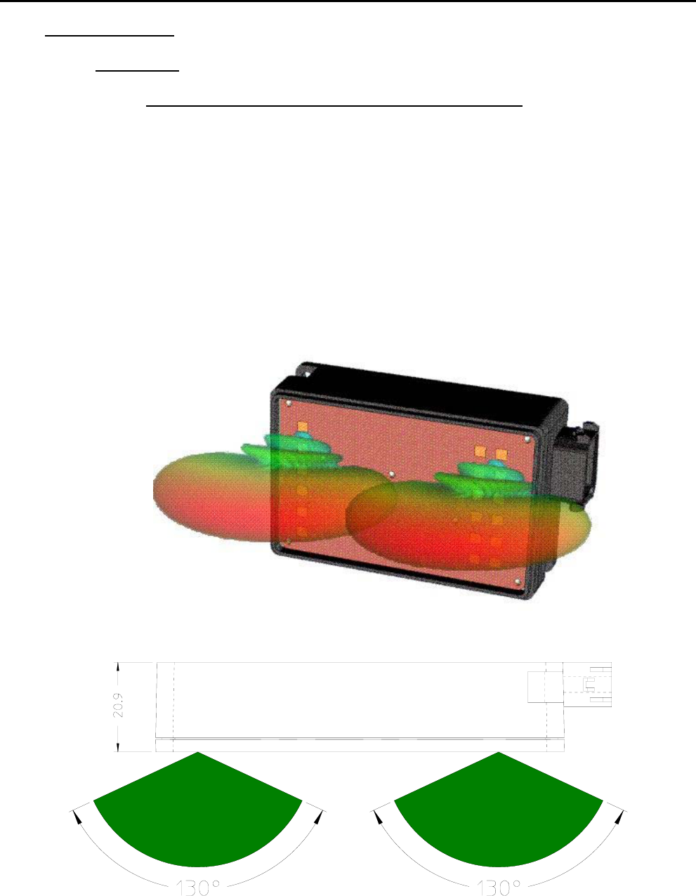
Figure 2 displays the detection area of the SLR sensor. One should differentiate
between the detection area of the sensor and the angle measurement area. The
angle measurement area is reduced to ±40° around bore sight whereas the
detection area is ±65°. The detection area is related to the 10dB points, this
means the area where the signal amplitude is reduced by 10dB compared to bore
sight direction.
Within the detection area of the antennas there must not be metal parts like
screws, mounting brackets, license plate etc. The impact reducing foam material,
clips or fascia laminations has to be avoided in that area.
Figure 2
Title: Installation Specifications and User Manual, Radar
Sensors Doc. No. E567781
INSTALLATION SPECIFICATION Rev. 001, Page 6 of 14
5.0 SPECIFICATIONS
5.2 SLR Sensor (cont’d)
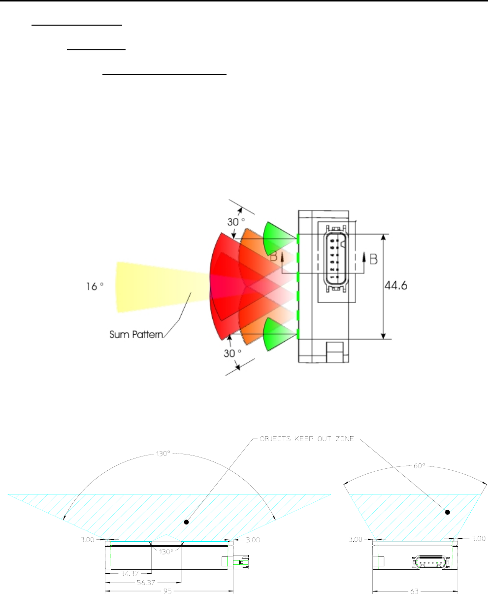
5.2.3 Detection Angle Elevation
Figure 3 shows the detection area of the antennas in elevation. The
detection area of ±8 ° is related to the 3dB points, this means the area
where the signal amplitude is reduced by 3dB compared to bore sight
direction. To avoid close range false objects there must not be metal
parts like screws, mounting brackets, license plate etc in an angle of
±30 ° (see figure 3). Impact reducing foam material, clips or fascia
laminations must be avoided in this area. Figure 4 shows details of
objects keep out zone.
Figure 3
Figure 4
Title: Installation Specifications and User Manual, Radar
Sensors Doc. No. E567781
INSTALLATION SPECIFICATION Rev. 001, Page 7 of 14
5.0 SPECIFICATIONS
5.3 Installation Specifications For Individual Sensors
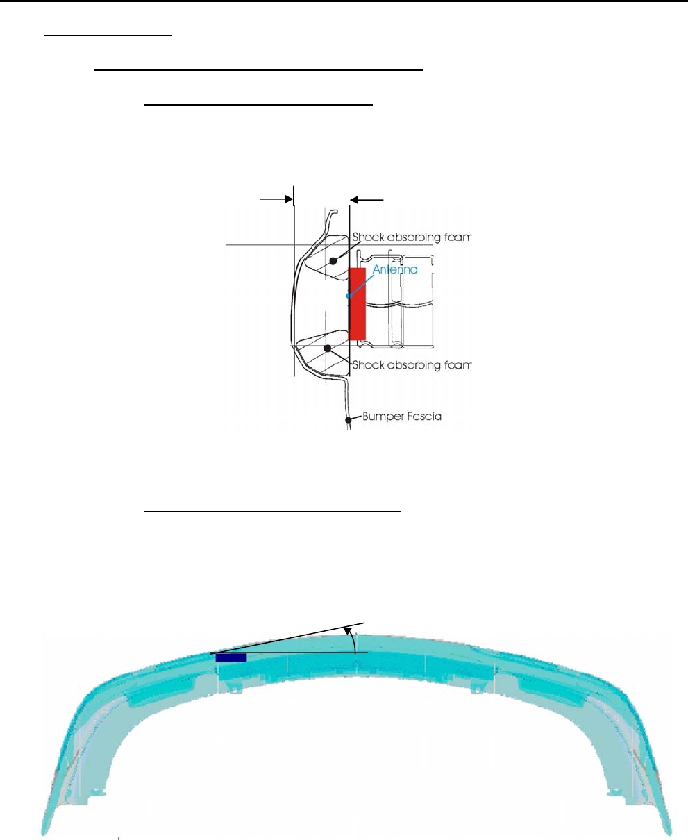
5.3.1 Distance To The Bumper Material
The distance of the SLR sensor to the bumper shall be between 5 and
20 mm. If the distance is below 5 mm a significant signal loss occurs. If
the distance is larger, error ranges may appear within the close range.
Figure 5
5.3.2 Angle with respect to bumper material
The angle ϕ of the sensor with regard to the bumper should be 0°,
meaning the sensor should be installed parallel to the bumper. If this is
not possible, an angle of ±10° shall not be exceeded. Other
orientations need to be tested to confirm proper operation.
Figure 6
5 – 20mm
ϕ
Title: Installation Specifications and User Manual, Radar
Sensors Doc. No. E567781
INSTALLATION SPECIFICATION Rev. 001, Page 8 of 14
5.0 SPECIFICATIONS
5.3 Installation Specifications For Individual Sensors (cont’d)
5.3.3 Effect Of Type- And Thickness Of Fascia Material
Autoliv has examined various fascia material samples with a thickness
of 2.5 – 4 mm. For those samples the radar signal is attenuated by
0.5 – 2 dB (corresponds to reduction of the range of coverage of
2 – 11%). The impact reducing material (foam) causes additional
attenuation, especially when water is absorbed. Therefore there shall
be no impact reducing material in the antenna areas as described in
5.2.2 – 5.2.3. There shall also be no metallic parts, snap-on contacts,
clips or double wall laminations in the antenna areas as described in
5.2.2 – 5.2.3.
Fascia loss effects can be optimized by proper control of the material
thickness and dielectric constant. For example, a fascia material
measured to have a 2.2 dielectric constant would have less than 1 dB of
loss at a thickness of 4.5 mm. Autoliv can analyze sample materials to
determine the dielectric constant and proper thickness for optimal
performance. Thickness and dielectric constant must be controlled to a
tolerance of ±10% max to ensure optimal performance.
5.3.4 Effect of the paint
Depending upon the type of paint, number of coatings, base coats
used, etc. the attenuation of the radar signal was measured between
2 and 5 dB (corresponds to reduction of coverage between 11 and
25%). Because attenuation has significant impact on performance,
prior inspection of the material and paint samples are suggested.
Autoliv can characterize painted fascia samples to determine the radar
signal loss effects. Autoliv sensor specifications assume a maximum
signal loss (2-way) of 4 dB due to fascia effects. Materials and paints
that exhibit greater than 4 dB loss will degrade the specified
performance. As noted in 5.3.3 performance can be optimized by
proper control of the fascia material thickness and dielectric constant.
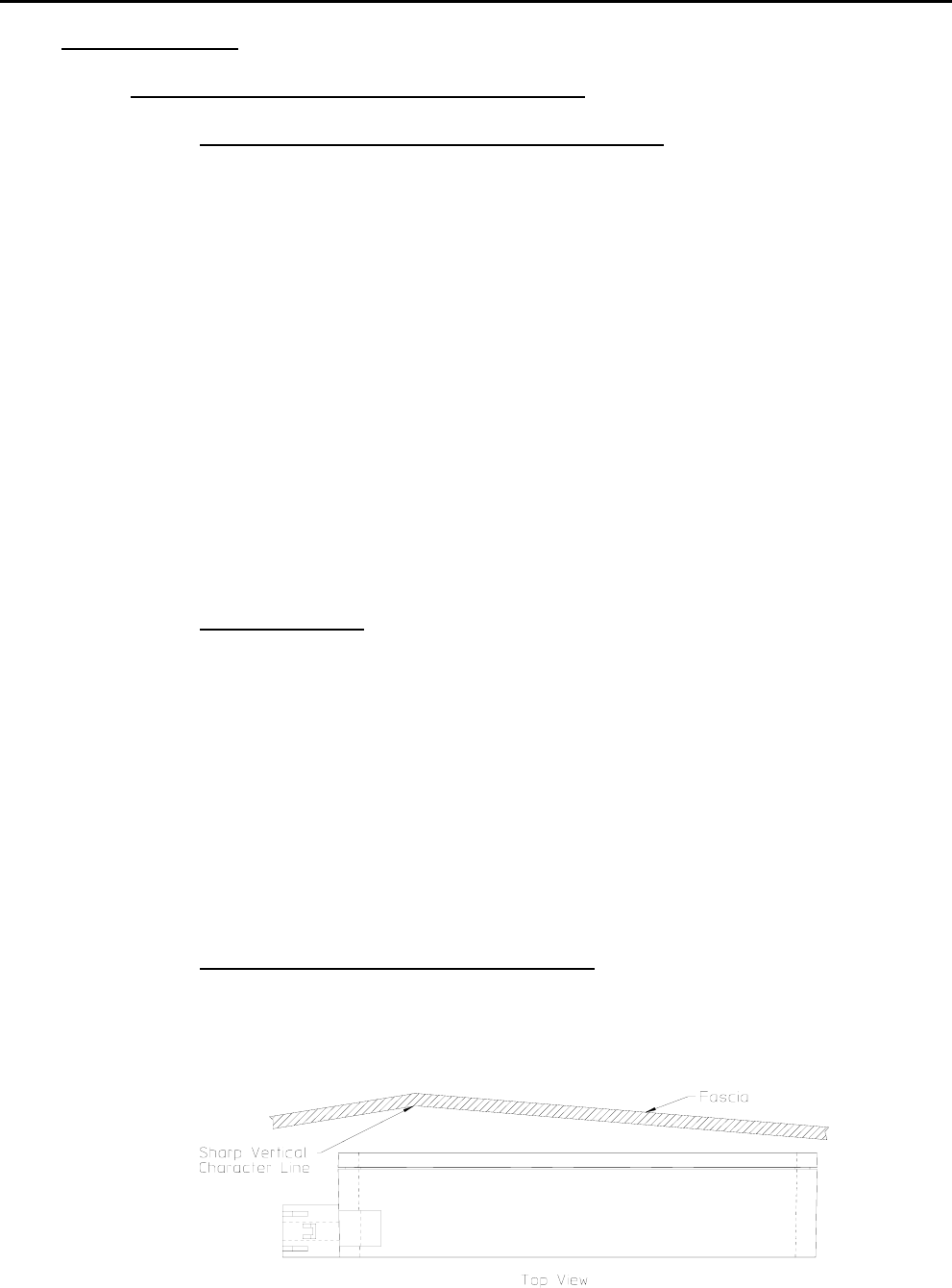
5.3.5 Smoothness of Fascia in Front of Antenna
Avoid sharp vertical or near vertical character lines in front of sensor
antenna. Horizontal character lines seem to have little effect on sensor
performance.

Title: Installation Specifications and User Manual, Radar
Sensors Doc. No. E567781
INSTALLATION SPECIFICATION Rev. 001, Page 9 of 14
5.0 SPECIFICATIONS
5.3 Installation Specifications For Individual Sensors (cont’d)
5.3.6 Environmental Conditions
The following lists the environmental conditions the sensor is designed
to operate in. The location and mounting of the sensor must not create
conditions that exceed the following:
1. Temperature extremes and applicable tests according to SAE
J1211 Table 1, Zone 2.1
2. Operational Integrity according to SAE J1812, Range 1
3. Functional Classification according to SAE J1812, Class B
4. Generic Environmental Requirements SAE J1879
Examples:
Operating Temperature: -40° to +85°C
Assumes non-moving air, sensor
backside surface exposed to free
air.
Max. Storage Temp: +105 °C
5. Temperature tests SAE J1211 4.1, 5.9 IEC68-2-1 Aa,
Ab, Ad, IEC68-2-2, Ba, Bb, Bd,
IEC68-2-33, IEC68-2-14, SAE
J1879 4.1, IEC68-2-18 Rb3,
IEC68-2-14 Nc, IEC68-2-5
6. Humidity test Per IEC68-2-56 Cb, Db IEC68-2-
30, IEC 68-2-10, IEC68-2-38, SAE
J1211 4.2, 5.9,
7. Mechanical Shock Per IEC 68-2-27 Ea & Eb & IEC
68-2-29
8. Vibration over Temp. Per IEC 68-2-64Fh & IEC 668-2-
14Nb, IEC68-2-50, IEC68-2-51
9. Free Fall Per IEC 68-2-32 Ed, Version 1
10. Constant Acceleration Per IEC 68-2-7
11. Resonance frequency Per IEC 68-2-6 Fc, SAE J1211
4.7, 5.9
12. Salt Spray Per IEC68-2-11 Ka , IEC68-2-52
13. Water Immersion/Protection Per DIN 40050-9 IP6K9K
14. Dust Protection Per DIN 40050-9 IP6K9K &
IEC529, 13.4
15. Fluid Compatibility according to installation area
Title: Installation Specifications and User Manual, Radar
Sensors Doc. No. E567781
INSTALLATION SPECIFICATION Rev. 001, Page 10 of 14
5.0 SPECIFICATIONS
5.3 Installation Specifications For Individual Sensors (cont’d)
5.3.7 Protection From Mud And Dirt Buildup
There will be performance degradation if excessive buildup occurs on
the antenna areas and especially for wet mud. Therefore Autoliv
strongly recommends the sensor mounting include provisions to protect
the antenna face from dirt and mud accumulation. The mounting
concept should prevent mud and dirt from entering the free space
between the sensor radome and the fascia. In addition the protection
features must not interfere with the antenna areas as described in
5.2.2 – 5.2.3.
In order to minimize any possible influence the protection feature might
have on the RF performance of the sensor it is recommended that the
material thickness and dielectric constant be controlled to minimize the
reflectivity of the material. Autoliv can characterize material samples
and provide a recommended thickness. The thickness and dielectric
constant must be controlled to a ±10% tolerance.
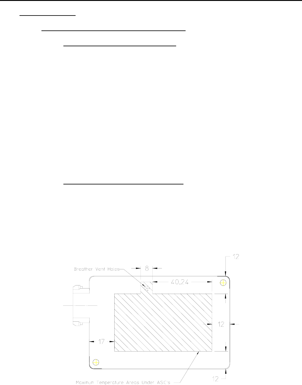
5.3.8 Sensor mounting thermal considerations
The sensor is specified to operate in a –40° to +85°C ambient, still air
environment. Natural convection and venting from the front and
backside surfaces of the sensor to the ambient air is assumed.
Therefore the mounting concept shall leave both the front radome and
backside area of the sensor exposed to the ambient air. Minimum area
to be left for the backside exposed is as shown below. Maximum
surface temperature in this region is +115°C at a maximum ambient of
+85°C.
Figure 7
Title: Installation Specifications and User Manual, Radar
Sensors Doc. No. E567781
INSTALLATION SPECIFICATION Rev. 001, Page 11 of 14
6.0 SLR SENSOR SYSTEM
The following observations refer to the combination of several SLR sensors into one
sensor system. Many applications require several sensors networked together to
achieve the desired function. The sensors should be placed in the best possible
location for optimal coverage and range performance relative to the specific
applications. The optimal locations will be highly dependent on the desired applications
and the bumper dimensions. Autoliv can perform analysis and characterization to
determine sensor locations to best achieve a desired performance. Attention should
be paid that the installation specifications for individual sensors from chapter 5 are
maintained. Due to the various installation situations and applications, a measurement
check is required to verify the actual installation implementation.
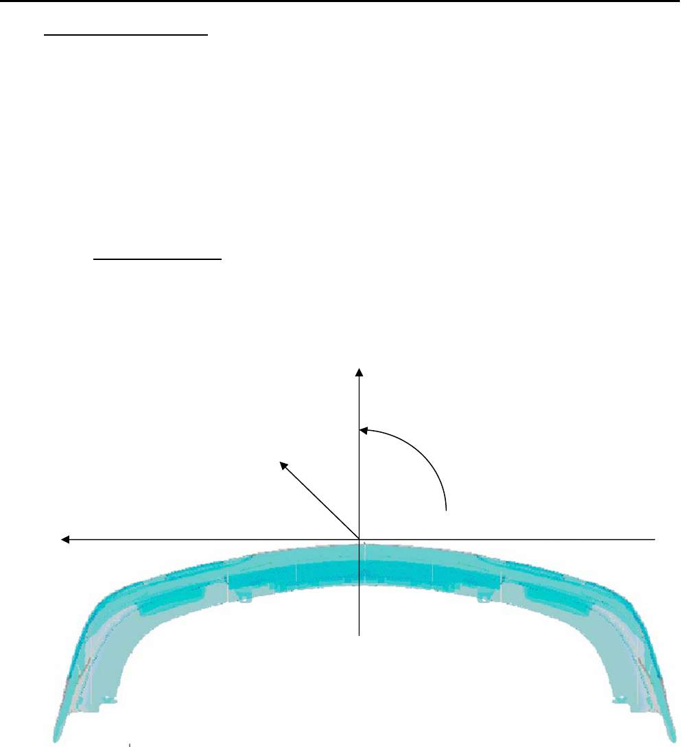
6.1. Coordinate System
Figure 8 shows the coordinate system used for identifying sensor position in a
multi-sensor application. The arrows indicate positive values. The most
forward location on the bumper was selected as reference point. The Z-axis is
the vertical axis. Z-values are indicated from the ground surface.
Figure 8
Y
Z
ϕ
X
Title: Installation Specifications and User Manual, Radar
Sensors Doc. No. E567781
INSTALLATION SPECIFICATION Rev. 001, Page 12 of 14
6.0 SLR SENSOR SYSTEM
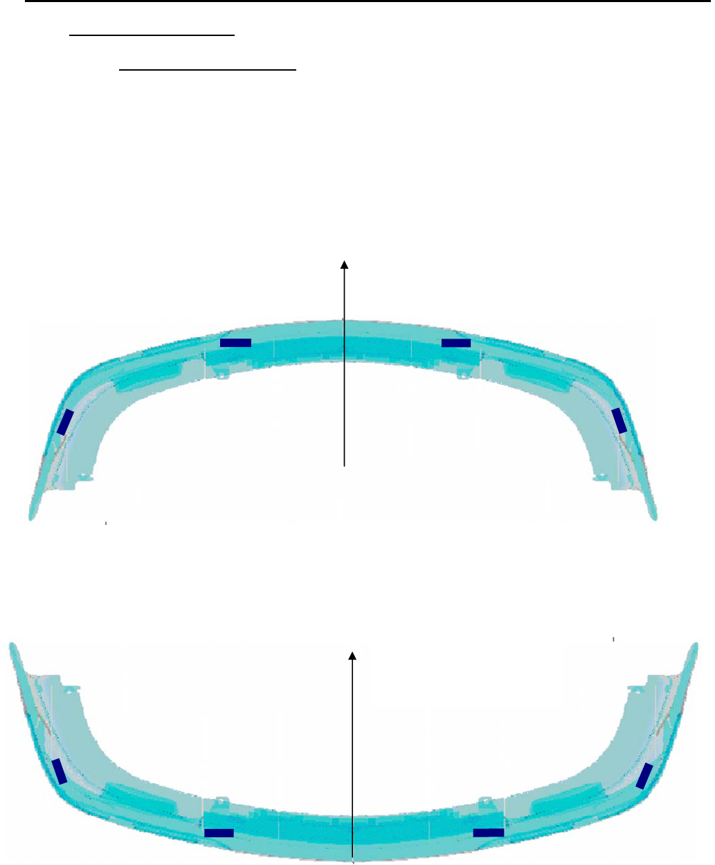
6.2. Numbering of the Sensors
The following provides a guideline for sensor numbering (addressing) in a
multi-sensor system. The example used is for a front and rear bumper system.
Each bumper contains up to 4 sensors connected on a private CAN bus. A
separate CAN bus is used for the front and rear bumpers. The sensors transmit
data over the CAN bus to a centralized processor which performs sensor data
fusion and runs the desired application.
Figure 9 shows the numbering used for a front sensor system.
Figure 9
Figure 10 shows the numbering used for a rear sensor system.
Figure 10
1F
2F 3F
4F
Driving direction
1
R
2R
3R
4R
Driving direction

Title: Installation Specifications and User Manual, Radar
Sensors Doc. No. E567781
INSTALLATION SPECIFICATION Rev. 001, Page 13 of 14
6.0 SLR SENSOR SYSTEM
6.3. Installation Dimensions
6.3.1 Y-direction
The Y location of the sensors will determine the extent of the coverage
zone and the size of any detection gaps. The location selections are
highly dependent on the desired application and bumper dimensions. In
general, for a 2 sensor longitudinal system sensors 2 &3 should be
located midway between the center of the bumper and the outer corner.
Bumper features (license plates etc.) may not allow this while
maintaining the guidelines of section 5. In this case the locations should
be as close to the ideal locations as possible while meeting the
requirements of section 5. A measurement check is required to verify
the actual installation implementation.
6.3.2 X-direction
The X location of the sensors not as critical as Y in terms of system
performance. In general the X locations will be dictated by the contour
of the bumper and the installation guidelines of section 5.
6.3.3 Azimuth angle
For best longitudinal coverage from sensors 2 & 3 the Azimuth angle of
the sensors has to be in the range of 0°. For systems, which are used
exclusively for parking distance control, larger angles up to 10° might be
sensible if required to improve range of coverage.
6.3.4 Elevation Angle
For best range performance the elevation angle of the sensors shall be
0 deg min, +1° max with respect to the ground (sensor radome surface
perpendicular (90°) to the ground). The main beam of the sensor (90°
to the installation position) may under no circumstances cross the plane
of the roadway before the desired coverage range.
For applications that only require short ranges (up to 5m) detection of
low objects (curbstones, low walls, etc.) may be desired. An incline
toward the ground of up to 10° can be used.
Title: Installation Specifications and User Manual, Radar
Sensors Doc. No. E567781
INSTALLATION SPECIFICATION Rev. 001, Page 14 of 14
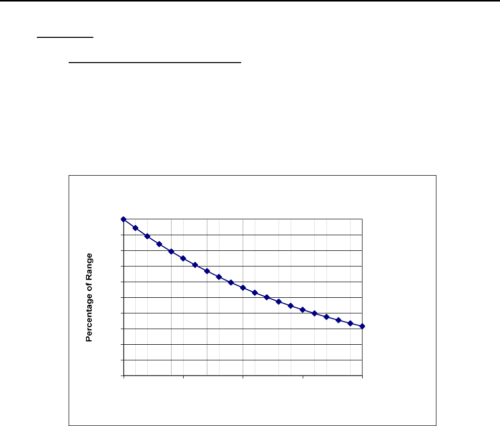
7.0 APPENDIX
7.1. Range Performance vs Attenuation
The chart below illustrates the effect of attenuation of the radar signals on the radar
sensor detection range. Factors that can cause attenuation of the radar signals include
fascia material, paint, dirt and mud buildup, foam material, or other mechanical
obstructions in the sensor field of view. For example, if a material is placed in front of the
sensor which attenuates the signal 12 dB (2 way loss) the maximum detection range of
the sensor will decrease by 50%.
Range vs Attenuation
0,00
0,10
0,20
0,30
0,40
0,50
0,60
0,70
0,80
0,90
1,00
0,00 5,00 10,00 15,00 20,00
Loss in dB
Figure 11
This device complies with Industry Canada RSS210 rules.
Operation is subject to the following two conditions:
1. This device may not cause interference and
2. This device must accept any interference, including interference that may cause
undesired operation of the device.