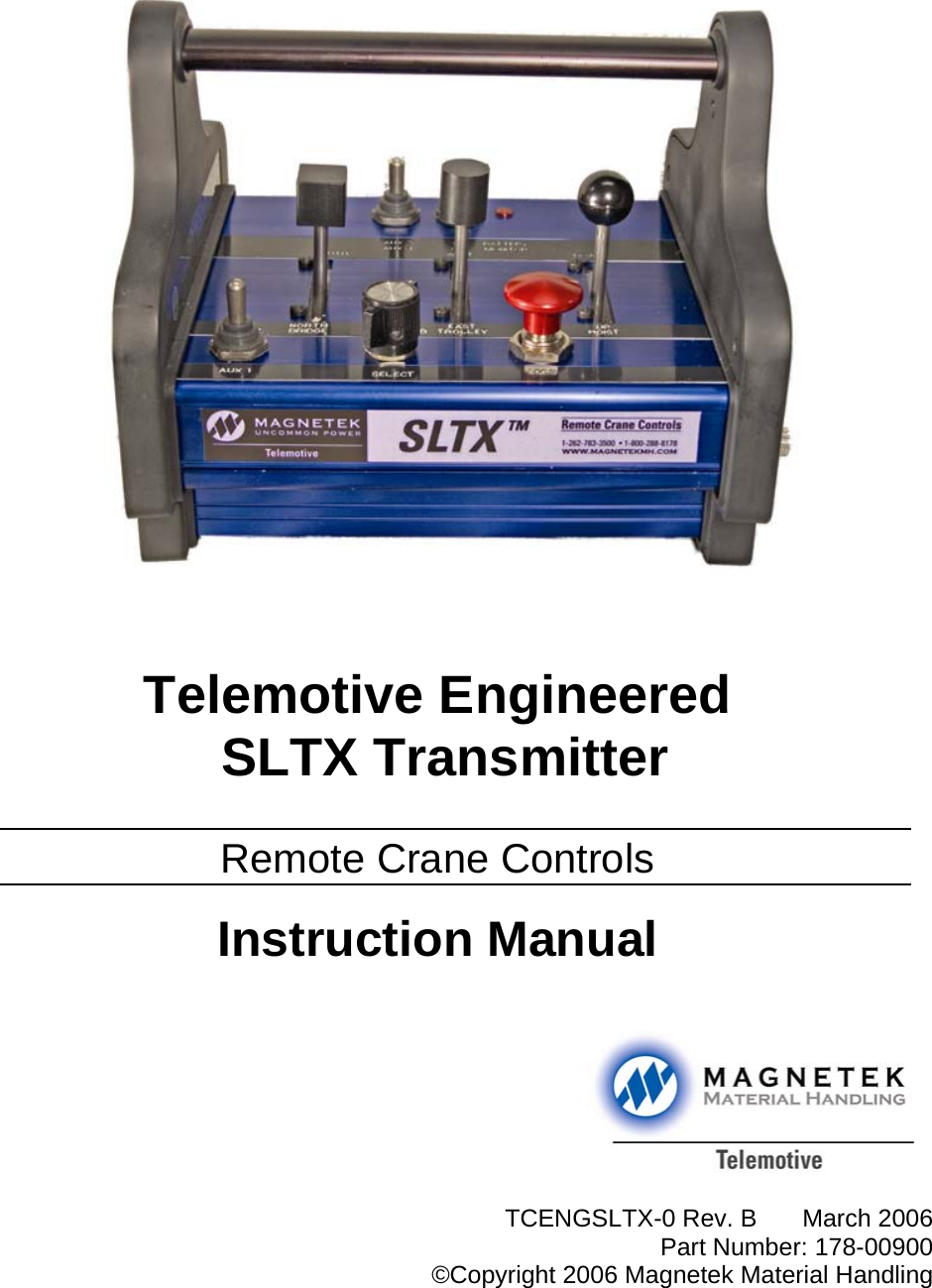
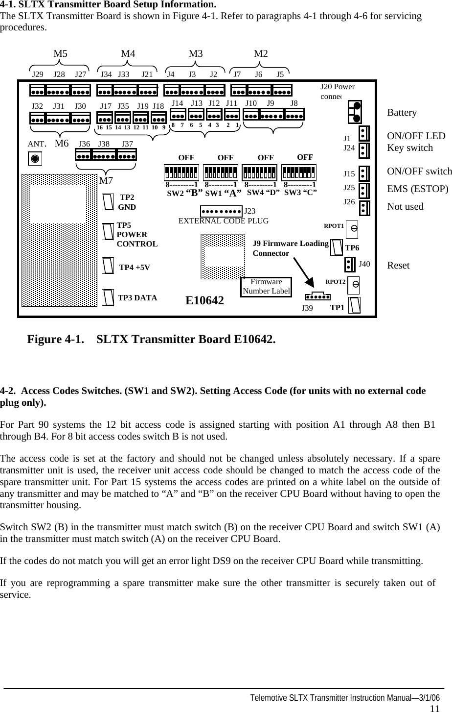
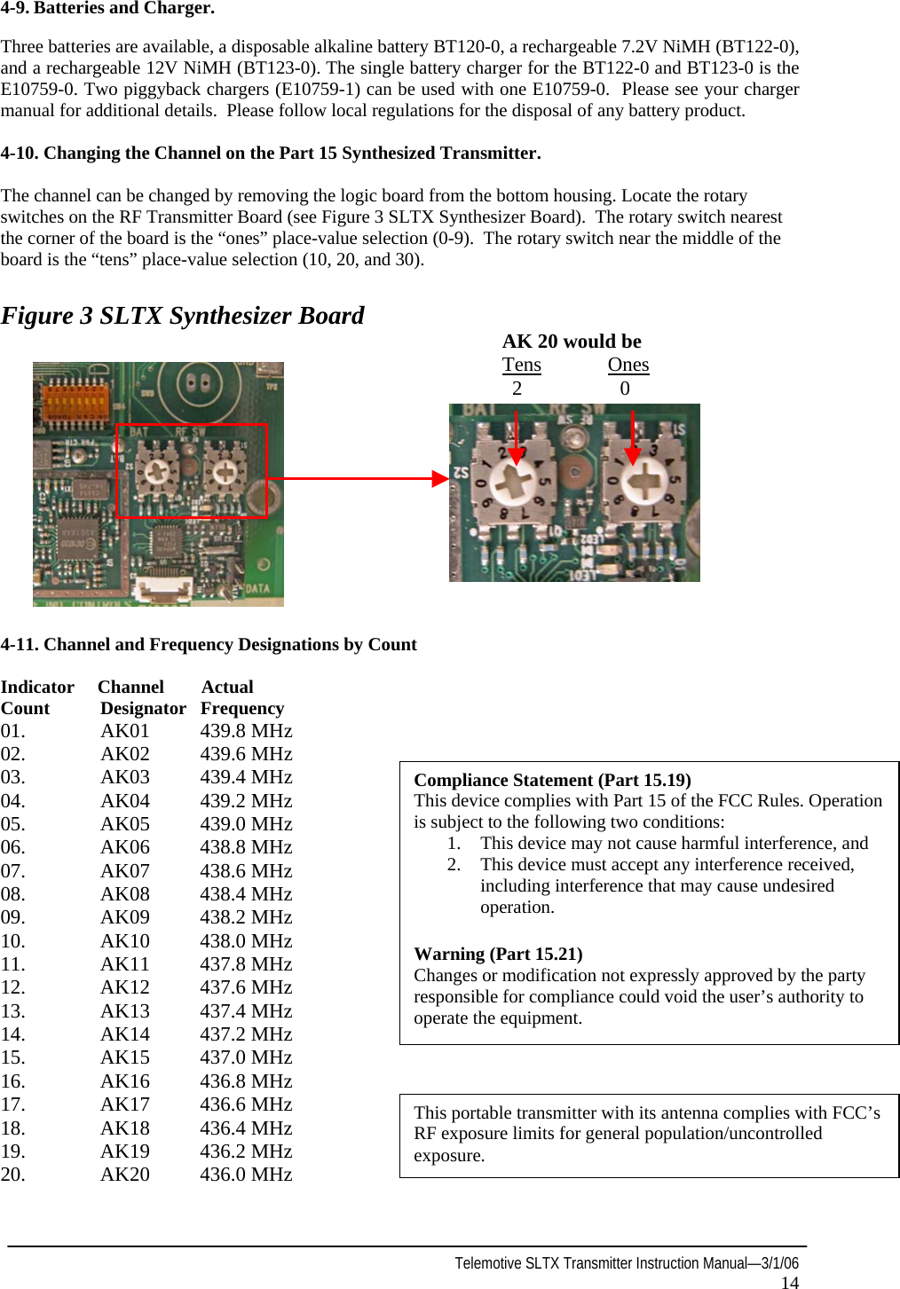
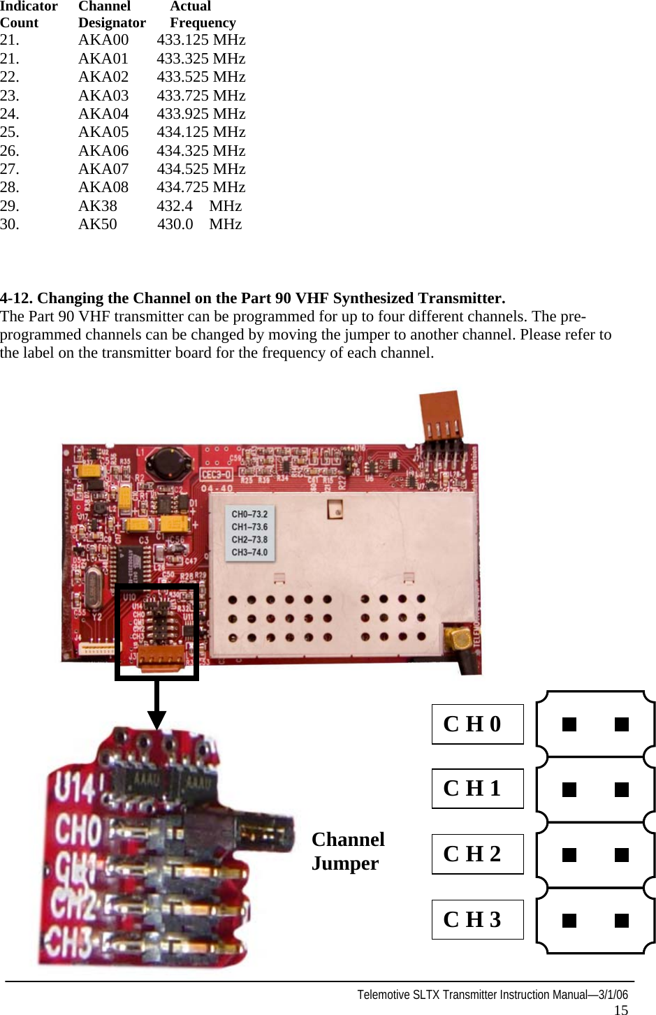
Magnetek 7276SLTX Remote Control Transmitter User Manual TCENGSLTX 0 Rev B 178 00900

Magnetek Remote Control Transmitter TCENGSLTX 0 Rev B 178 00900

Manual

              Telemotive Engineered  SLTX Transmitter  Remote Crane Controls  Instruction Manual           TCENGSLTX-0 Rev. B  March 2006Part Number: 178-00900©Copyright 2006 Magnetek Material Handling
                                2006 MAGNETEK MATERIAL HANDLING All rights reserved. This notice applies to all copyrighted materials included with this product, including, but not limited to, this manual and software embodied within the product. This manual is intended for the sole use of the persons to whom it is provided, and any unauthorized distribution of the manual or dispersal of its contents is strictly forbidden. This manual may not be reproduced in whole or in part by any means, whatsoever, without the expressed written permission of MAGNETEK.
 Telemotive SLTX Transmitter Instruction Manual—3/1/06 1  Table of Contents  Your New Radio Remote and Service Information        p.2  Safety Information        p.3-9  3-1. Power “ON-OFF” Switch      p.10  3-2. E-STOP         p.10  3-3. Motion Push Buttons or Levers      p.10  3-4. Transmitter LED Indicator      p.10  3-5. Time-Out Timer        p.10  3-6. Key Switch (For Part 15 models not using active ESTOP,          keyswitch disables power to transmitter circuitry only)     p.10  4-1. SLTX Transmitter Board Set-up Information        p.11  4-2. Setting Access Code (For units with no external code plug only)  p.11-12  4-3. Programming Switches       p. 12  4-4. 10K Series SLTX Programming Switches        p.12-13  4-5. To Check Data        p. 13  4-6. Battery Monitor        p.13  4-7. Analog Voltage Reference      p.13  4-8. Transmit LED        p.13  4-9. Batteries and Charger       p.14  4-10. Changing the Channel on the Part 15 Synthesized Transmitter  p.14  4-11. Channels and Frequency Designating by Count      p.14-15  4-12. Changing the Channel on the Part 90 VHF Synthesized Transmitter  p.15  4-13 Replacement Parts       p.16
  Telemotive SLTX Transmitter Instruction Manual—3/1/06 2 Your New Radio Remote Thank you for your purchase of Magnetek’s Telemotive® brand SLTX Radio Remote Crane Control.  Magnetek has set a whole new standard in radio-remote performance, dependability, and value with this unique new line of belly box transmitters. Without a doubt, our Telemotive SLTX is the ultimate solution for having precise, undeterred, and safe control of your material. If your product ever needs modification or service, please contact one of our representatives at the following locations:      U.S. Service Information For questions regarding service or technical information, contact 1-866-MAG-SERV (1-866-624-7378).   Magnetek Material Handling  N49 W13650 Campbell Drive Menomonee Falls, WI 53051  Telephone:    800-288-8178  Website:   www.magnetekmh.com e-mail:    info@magnetekmh.com  Fax Numbers Main:      800-298-3503 Sales:      262-783-3510 Service:    262-783-3508  For Canada Service Information Contact Berlet Electronics:  Phone: 1-905-564-2710 Fax: 1-905.564.2755
 Telemotive SLTX Transmitter Instruction Manual—3/1/06 3  1-1. Warnings, Cautions And Notes. Throughout this document WARNING, CAUTION and NOTE statements have been deliberately placed to highlight items critical to the protection of personnel and equipment. WARNING – A warning highlights an essential operating or maintenance procedure, practice, etc. which if not strictly observed, could result in injury or death of personnel, or long term physi-cal hazards. Warnings are highlighted as shown below:   WARNING CAUTION – A caution highlights an essential operating or maintenance procedure, practice, etc. which if not strictly observed, could result in damage to, or destruction of equipment, or loss of functional effectiveness. Cautions are high-lighted as shown below:   CAUTION  NOTE – A note highlights an essential operating or maintenance procedure, condition or state-ment. Notes are shown as below: NOTE WARNINGS, CAUTIONS AND NOTES SHOULD NEVER BE DISREGARDED. The safety rules in this section are not intended to replace any rules or regulations of any appli-cable local, state, or federal governing organiza-tions. Always follow your local lockout and tag out procedure when maintaining any radio equipment. The following information is intended to be used in conjunction with other rules or regulations already in existence. It is important to read all of the safety information contained in this section before installing or operating the Radio Control System. 1-2. Critical Installation Considerations.   WARNING ALL EQUIPMENT MUST HAVE A MAINLINE CONTACTOR INSTALLED AND ALL TRACKED CRANES AND SIMILAR EQUIPMENT MUST HAVE A BRAKE IN-STALLED. FAILURE TO FOLLOW THIS WARNING COULD RESULT IN SERIOUS INJURY OR DEATH AND DAMAGE TO EQUIPMENT.    WARNING ON ALL REMOTE CONTROLLED CRANES AN AUDIBLE AND/OR VISUAL WARNING MEANS MUST BE PROVIDED. THESE AU-DIBLE AND/OR VISUAL WARNING DE-VICES MUST MEET ALL GOVERNMENTAL REQUIREMENTS. FAILURE TO FOLLOW THIS WARNING COULD RESULT IN SERI-OUS INJURY OR DEATH AND DAMAGE TO EQUIPMENT.   WARNING PLEASE FOLLOW YOUR LOCAL LOCKOUT TAGOUT PROCEDURE BEFORE MAINTAINING ANY REMOTE CONTROL EQUIPMENT.  ALWAYS REMOVE ALL ELECTRICAL POWER FROM THE CRANE OR MACHINERY BEFORE ATTEMPTING ANY INSTALLATION PROCEDURES. DE-ENERGIZE AND TAG OUT ALL SOURCES OF ELECTRICAL POWER BEFORE TOUCH TESTING ANY EQUIPMENT. FAILURE TO FOLLOW THIS WARNING COULD RESULT IN SERIOUS INJURY OR DEATH AND DAMAGE TO EQUIPMENT.
  Telemotive SLTX Transmitter Instruction Manual—3/1/06 4   WARNING THE DIRECT OUTPUTS OF THIS PRODUCT ARE NOT DESIGNED TO INTERFACE DI-RECTLY TO TWO STATE SAFETY CRITI-CAL MAINTAINED FUNCTIONS, I.E., MAGNETS, VACUUM LIFTS, PUMPS, EMERGENCY EQUIPMENT, ETC. A ME-CHANICALLY LOCKING INTERMEDIATE RELAY SYSTEM WITH SEPARATE POWER CONSIDERATIONS MUST BE PROVIDED. FAILURE TO FOLLOW THIS WARNING COULD RESULT IN SERIOUS INJURY OR DEATH AND DAMAGE TO EQUIPMENT. 1-3. General. Radio controlled overhead cranes and other ma-terial handling equipment operates in several di-rections. They are large, bulky pieces of equip-ment that handle heavy loads efficiently at high speeds. Quite frequently, the equipment is oper-ated in areas where people are working on the floor below. The crane operator must exercise extreme caution at all times. Workers must con-stantly be alert to avoid accidents. The following rules have been included to indicate how your careful and thoughtful actions may prevent inju-ries, damage to equipment, or even save a life. If radio controlled material-handling equipment is operated from the cab, special care must be taken to secure the transmitter. Refer to section titled Section 2-8. Boarding The Crane for specific safety rules. 1-4. Persons Authorized To Operate Radio Controlled Cranes. Only properly trained persons designated by management should be permitted to operate ra-dio-controlled cranes. Radio controlled cranes should not be operated by any person who cannot read or understand signs, notices and operating instructions that pertain to the crane. Radio controlled cranes should not be operated by any person with insufficient eyesight or hearing or by any person who may be suffering from a disorder or illness or is taking any medi-cation that may cause loss of crane control. 1-5. Training Checklist For Crane Operators. Anyone being trained to operate a radio-con-trolled crane should possess as a minimum the following knowledge and skills before operating the crane: The operator should have knowledge of hazards pertaining to crane operation. The operator should have knowledge of the safety rules for radio-controlled cranes. The operator should have the ability to judge distance of moving objects. The operator should have knowledge of the radio transmitter. The operator should know the limit switch test procedure. The operator should know, where authorized, instructions for plugging motions. The operator should have knowledge of the use of crane warning lights and alarms. The operator should have knowledge of observing crane signal lights. The operator should be trained to avoid striking any obstructions. The operator should have knowledge of the proper clearance of lifts or hooks before moving bridge or trolley. The operator should have knowledge of the proper storage space for radio control box when not in use. The operator should be trained in transferring radio control box to another person. The operator should be trained how and when to report unsafe or unusual operating conditions. The operator should be trained how to exhibit caution in approaching bridge or trolley bump-ers. The operator should know equipment capacity. The operator should be trained in making lifts below floor level.
  Telemotive SLTX Transmitter Instruction Manual—3/1/06 5 The operator should be trained in making side pulls. The operator should know how to keep himself and other people clear of lifts and to avoid "pinch" points. The operator should know cable and hook inspection procedures. The operator should know procedures for testing hoist, trolley, and bridge brakes. The operator should know and follow the local lockout and tagout procedures. 1-6. Operating Area. Aisles between equipment, stock, etc., should be free of obstructions so the crane operator can move freely. These aisles should be a minimum of three feet (one meter) wide, or meet local regulations. Crane operators should always position them-selves for the best view of the crane they are controlling. The crane should never be operated blindly. The operator should stay as close to the crane load as possible. Operators should never position themselves in a "pinch" point. 1-7. Transmitter Unit. Transmitter switches should never be mechani-cally blocked ON or OFF for any crane motion. When not in use turn the transmitter OFF. A se-cure storage space should be provided for the transmitter unit and the transmitter unit should always be placed there when not in use. This precaution will prevent unauthorized people from operating the crane. Spare transmitters should be stored in a secure storage space and only removed from the storage space after the current transmitter in use has been turned OFF, taken out of the service area and secured. 1-8. Operating The Crane. 1-9. Pre-operation Test. At the start of each work shift, or when a new operator takes control of the crane, operators shall do, as a minimum, the following steps before making lifts with any crane or hoist:  Test the upper-limit switch. Slowly raise the unloaded hook block until the limit switch trips. When checking limit switches the hoist should be centered over an area free of personnel and equipment. Visually inspect the hook, load lines, trolley, and bridge as much as possible from the operator's station; in most instances, this will be the floor of the building. The bridge and trolley brakes should be tested. On transmitter units equipped with two or more speeds, use the "lowest" speed when testing braking devices. When lifting maximum loads, the crane operator should test the hoist brakes by raising the load a few inches from the floor. If the brakes do not hold, the load should immediately be lowered to the floor. If provided, test the lower-limit switch. Test all warning devices. Test all direction and speed controls for both bridge and trolley travel. Test all bridge and trolley limit switches, where provided, if operation will bring the equipment in close proximity to the limit switches. Test the transmitter emergency stop. Test the hoist brake to verify there is no drift without a load. If any crane or hoist fails any of the above tests notify the supervisor and lock out and tagout for repair. 1-10. General Rules For Operation. Consult the crane manufacturer, local and governmental regulations for complete rules of operation. In general the following rules apply to remotely controlled cranes: The limit switches should never be used as a regular stopping device. They are intended to be protective devices. Do not make lifts in excess of the equipment rated capacity.
  Telemotive SLTX Transmitter Instruction Manual—3/1/06 6 The bridge and trolley should be centered di-rectly over the load when the load is raised to prevent swinging when making lifts. A crane designed for this purpose and only with supervisor permission should make side pulls. When a lift is being made, the crane operator should not be positioned in the line of travel. The crane or hoist should be operated from a position either to the side or opposite from the direction of travel. When raising or lowering a load, proceed slowly and make certain the load is under control. Tag lines should be used for handling unusual lengths or bulky loads. Remove slack from chains or slings gradually. Make certain all personnel are clear before making a lift. The crane operator should keep all body parts away from the lift and should never be posi-tioned under the lift. Do not make a lift or move a load if anyone is in a location where they could be struck by the crane or the load. If the crane operator is being assisted, the crane should not be moved until the assistant signals they are clear of the crane and its load. When a load is hanging from the crane hook and the crane is being moved, the crane operator should sound all warning devices frequently. Loads should not be carried over workers heads. If a worker is in the path of crane travel, the crane operator should stop the crane and clear the area before proceeding. Runway stops or other cranes should never be bumped into. When moving the crane, the crane operator should be sure that the hook block and attach-ments or cables will not catch on nearby equipment. Slings, chains, or cables should never be dragged along the floor. Unless required for operator safety, gloves should not be worn when operating the trans-mitter unit. All loose materials or parts should be removed from the load before starting the lift. The crane operator should always hoist lifts high enough to clear all equipment and workers. The crane operator should never permit anyone to ride on the load or hook except when author-ized by the supervisor. When another crane on the same runway is sta-tionary with a load hanging, the crane operator should maintain a safe distance between the sta-tionary crane and the one under their control. Never leave suspended loads unattended. In an emergency, if the crane is inoperative and a load suspended, notify the supervisor immediately, barricade and post signs on the floor beneath crane and load.  If power to the crane is removed, the crane op-erator should turn the transmitter unit OFF and keep it OFF until power is restored. If the crane fails to respond properly, the crane operator should stop operation, turn the trans-mitter unit OFF and immediately report the con-dition to their supervisor. Outdoor cranes, which are subject to movement by wind, should be securely anchored when left unattended. If the crane is equipped with bridge brakes, the parking brake should be set immedi-ately. 1-11.  Boarding The Crane. The crane should not be boarded without permis-sion of the supervisor. The crane operator should turn off the transmitter and take it with them when boarding the crane. If more than one person is boarding the crane, one person should be made responsible for en-suring all personnel are off the crane before the system is returned to operation. 1-12.  Crane Maintenance And Repair. Qualified personnel must maintain a regularly, i.e., such as monthly, scheduled crane inspection. During this crane inspection the functionality and safety of the crane remote control must also be tested. The inspection shall include, but not  be limited to items listed in Section 2-11. Condition of The Radio Controlled Crane. Consult crane manufacturer, local and governmental regulations for recommended
  Telemotive SLTX Transmitter Instruction Manual—3/1/06 7 inspection intervals and proper inspection procedures. Problems noted during this inspection must be repaired before using the crane or the remote control. Minor repairs include routine maintenance and repairs such as greasing, cleaning and control troubleshooting. All other repairs should be con-sidered major. If the repair crew consists of more than one person, one person should be desig-nated as the repair crew leader with the follow-ing responsibilities. If the repair crew consists of only one person, that person has the following responsibilities: For minor repairs, warning signs should be placed on the floor beneath the crane or sus-pended from the crane. For major repairs, the floor area below the crane should be roped off. When major repairs are to take place, all persons operating other cranes on the same or adjacent runways, must be notified prior to starting repairs. Notification should include the nature of the repair, safeguards provided, and movement limitations while repairs are in progress. When practical, radio controlled cranes which cannot be moved during repairs must be pro-tected against being bumped by other cranes on the runway. Bumpers should be installed on the exposed side or sides of the crane under repair. They should be placed as far away as possible. The location of these bumpers should be indi-cated by red lights placed so that they are clearly visible to other crane operators traveling on the same runway. When it is not possible to use bumpers, red lights must be placed so they are clearly visible to other crane operators traveling on the same runway to indicate the restricted travel zone. All crane operators on the same runway must be informed of the repair effort and thoroughly instructed to what their operations are limited to and informed they will be notified when repairs are completed. If any hazard involving the repairmen exists when there is a runway adjacent to the crane un-der repair, the adjacent runway should be blocked off as described above. When it is nec-essary to continue crane operation on the adja-cent runways, warning lights must be installed and be visible to operators of cranes on those runways. All cranes should come to a complete stop prior to entering the restricted area and should proceed through this area only after re-ceiving permission from a signal person desig-nated for this purpose. Access of persons to and from the crane being repaired should be under control of the repair crew leader. When boarding the crane, the transmitter should be turned OFF and the transmitter should remain with the repair crew leader. The leader should board the crane first, open and lock out the main switch, and then signal the other members of the crew it is safe to board the crane. If work on the crane is to be done in areas not protected by standard handrails, the repair crew should wear approved safety belts. All tools and equipment should be moved onto the crane by the use of hand lines. The tools and equipment should be adequately secured to the hand lines. If it is necessary to have the crane control cir-cuits energized, all power circuits for crane movement must be opened prior to energizing the control circuits. All personnel and tools should be moved to a safe spot before moving the crane during repairs. Headroom is at a minimum in some crane cabs and on some crane walkways. Caution should be exercised when boarding or working on cranes. Hard hats should be worn whenever possible. When repairs are finished, all personnel, tools and repair equipment should be removed before energizing the crane circuits. 1-13.  Using The Crane As A Work Platform. When the crane is to be used as a stationary work platform, follow all rules provided in Section 2-9. Crane Maintenance and Repair. When it is necessary for the crane to be moved from time to time, the crane operator should board the crane with the transmitter unit. The crane operator should ensure all personnel working on the crane are in a secure position before moving the crane to the next workstation. It should also be the crane operator’s responsibility to ensure the main switch is open and locked down before work is resumed.
  Telemotive SLTX Transmitter Instruction Manual—3/1/06 8   WARNING THE CRANE OPERATOR SHOULD NOT AT-TEMPT TO REPAIR ANY OF THE ITEMS STATED BELOW. THE CRANE CONDITION SHOULD BE REPORTED TO THE SUPERVI-SOR. FAILURE TO FOLLOW THIS WARN-ING COULD RESULT IN SERIOUS INJURY OR DEATH AND DAMAGE TO EQUIP-MENT. 1-14. Condition Of The Radio Controlled Crane. If the crane fails to respond properly, the crane operator(s) should notify their supervisor. When serious conditions are noticed (conditions that make the crane unsafe to operate), the crane should be shut down immediately and the super-visor notified. The following is a list of some of the items that should be included in the report. (See the crane manufacturer for specifics and possible additional items): Condition of hoisting cable and hook block (bro-ken strands, clipped sheave wheels, etc.). Condition of brakes (hoist, trolley, and bridge). (No bluing, rivets on shoes showing, glazing, etc.). Condition of trolley and rail stops. Condition of bridge structure. Condition of festoon system. Broken welds in any part of the crane structure. Proper fluid levels and lubrication. Condition of bridge and trolley stops. Carbon dust or signs of burning on the covers of motors. Indication of fluid, oil or grease leaks. Condition of rail sweeps. Walkways require handrails and ladders are sturdy, in place and not loose. Protective guards are in place for all moving parts. Alignment of bridge (screeching or squealing wheels indicate bridge is out of line). Broken, cracked, or chipped rails on trolley or runway. Condition of limit switches. Condition of electrical and mechanical control (electrical or mechanical defects which cause faulty operation such as uncommanded stopping or starting of any crane motions, warning de-vices, lights, or auxiliary functions). Condition of gears (grinding or squealing may indicate foreign materials in gear teeth or a lack of lubrication. All controls (especially E-STOPs) are in place and in working order. Frequent relay tripping of power circuits. Mechanical parts loosened by vibration (loose rivets, covers, bolts, etc.). Uneven riding (worn or damaged wheels). Condition of collector shoes or bars. Condition of warning or signal lights and horns. (Burned out or broken). 1-15.   Batteries    WARNING KNOW AND FOLLOW PROPER BATTERY HANDLING, CHARGING AND DISPOSAL PROCEDURES. IMPROPER BATTERY PRO-CEDURES CAN CAUSE BATTERIES TO EXPLODE OR DO OTHER SERIOUS DAM-AGE. FAILURE TO FOLLOW THIS WARN-ING COULD RESULT IN SERIOUS INJURY OR DEATH AND DAMAGE TO EQUIP-MENT.
  Telemotive SLTX Transmitter Instruction Manual—3/1/06 9 1-16. Battery  Handling. Use only batteries approved by Telemotive for the specific product. Do not dispose of a battery pack in fire; it may explode.  Do not attempt to open the battery pack.  Do not short circuit battery. For intrinsically safe environments only use specified Telemotive intrinsically safe batteries. Keep the battery pack environment cool during charging operation and storage, (i.e., not in direct sunlight or close to a heating source). 1-17. Battery  Charging. For those transmitters equipped with battery chargers, please familiarize all users with the instructions of the charger before attempting to use.  Use only Telemotive approved chargers for the appropriate battery pack. Do not attempt to charge non-rechargeable bat-tery packs. Avoid charging the battery pack for more than 24 hours at a time. Do not charge batteries in a hazardous environ-ment.  Do not short charger.  Do not attempt to charge a damaged battery.  Do not attempt to use a battery that is leaking, swollen or corroded. Charger units are not intended for outdoor use. Use only indoors. 1-18. Battery  Disposa l. Before disposing of batteries consult local and governmental regulatory requirements for proper disposal procedure.
 Telemotive SLTX Transmitter Instruction Manual—3/1/06 10  CAUTION Before operating the transmitter, familiarize yourself with all safety information in this manual and any other local, state, or federal rules or regulations already in existence.  3-1. Power “ON-OFF” Switch (Turns transmitter and receiver ON and OFF). With the key switch (optional) engaged, pressing the ON/OFF push-button switch (Part 15) starts the transmitter, pushing it again starts the receiver; or toggling the ON/OFF toggle switch (Part 90) turns the transmitter and the receiver ON. If the transmitter is ON the BATT MONITOR light is ON or flashing. Pushing the ON/OFF button again (Part 15), or resetting the toggle switch to OFF (Part 90), will turn the transmitter and receiver OFF.    3-2. E-STOP (For Emergency Stopping only). When depressed, the MCR relay is opened, the receiver shuts down, and power to the equipment is immediately stopped. Under normal operating conditions, the E-STOP must be in the raised position. The transmitter must be turned OFF and ON again to restore normal operation. To be used for emergency stopping only, not for normal system shut down. The E-STOP will not function with the optional key switch turned OFF.   3-3. Motion Push Buttons, Levers. To activate motor functions, press and hold the push-button or lever that corresponds to the desired motion. The extent to which the push-button or lever is pushed, dictates the speed of the motor function.   3-4. Transmitter LED Indicator. The transmitter LED (red) indicates the transmitter is on, or transmitting, or has a low battery voltage. A slow flash rate indicates the unit is ON. A rapid flash rate indicates the unit is transmitting (when a function or control is activated). If the battery goes below a safe level, the LED will not light. Replace battery soon.   3-5. Time-Out-Timer. Unless this function is disabled, the transmitter will turn itself OFF if not used for 15 minutes.   3-6. Key Switch. (For Part 15 Models not using active ESTOP, disables power to transmitter circuitry only). For models so equipped, turning the key OFF and removing it will disable the transmitter. If the key switch is turned OFF with the transmitter and receiver on, the key switch must be turned ON again to use the on/off pushbutton or E-STOP. Turning the key switch to ON enables power to the transmitter unit, but does not activate the transmitter controls or turn ON the receiver. The ON/OFF push button must be pushed to turn the transmitter and receiver ON or OFF. Under normal procedures it is recommended that the unit be turned OFF with the ON/OFF push button before turning OFF the key switch.
 Telemotive SLTX Transmitter Instruction Manual—3/1/06 11  Figure 4-1. SLTX Transmitter Board E10642. TP2 GND TP1 TP3 DATA RPOT2 OFF 8---------1 SW1 “A” OFF 8---------1 SW2 “B” OFF 8---------1  SW3 “C” E10642  EEPPRROOMMTP4 +5V J9 Firmware Loading Connector Firmware  Number Label OFF 8---------1  SW4 “D” TP5 POWER CONTROL  TP6 J29     J28     J27       J34   J33      J21       J4       J3       J2        J7       J6       J5J32     J31     J30       J17   J35    J19  J18    J14    J13   J12   J11    J10     J9        J8      ANT.   M6     J36    J38      J37         J20 Power connector J1 J24  J15  J25  J26 J40 J39RPOT1 J23       M5                     M4                     M3                    M2 16  15  14  13  12  11  10   9  8    7    6    5    4   3     2    1 M7 EXTERNAL CODE PLUG Battery  ON/OFF LED Key switch  ON/OFF switch  EMS (ESTOP)  Not used     Reset 4-1. SLTX Transmitter Board Setup Information. The SLTX Transmitter Board is shown in Figure 4-1. Refer to paragraphs 4-1 through 4-6 for servicing procedures. 4-2.  Access Codes Switches. (SW1 and SW2). Setting Access Code (for units with no external code plug only).  For Part 90 systems the 12 bit access code is assigned starting with position A1 through A8 then B1 through B4. For 8 bit access codes switch B is not used. The access code is set at the factory and should not be changed unless absolutely necessary. If a spare transmitter unit is used, the receiver unit access code should be changed to match the access code of the spare transmitter unit. For Part 15 systems the access codes are printed on a white label on the outside of any transmitter and may be matched to “A” and “B” on the receiver CPU Board without having to open the transmitter housing.  Switch SW2 (B) in the transmitter must match switch (B) on the receiver CPU Board and switch SW1 (A) in the transmitter must match switch (A) on the receiver CPU Board. If the codes do not match you will get an error light DS9 on the receiver CPU Board while transmitting.  If you are reprogramming a spare transmitter make sure the other transmitter is securely taken out of service.
 Telemotive SLTX Transmitter Instruction Manual—3/1/06 12    WARNING TWO OPERATIONAL TRANSMITTERS WITH THE SAME ACCESS CODES OPERATING AT THE SAME TIME IS A DEFINITE SAFETY HAZARD. FAILURE TO FOLLOW THIS WARNING COULD RESULT IN SERIOUS INJURY OR DEATH AND DAMAGE TO EQUIPMENT. Telemotive receivers are shipped with the access code settings for the transmitter marked on the receiver door.  Also a label on the transmitter lists the access code settings inside. The positions on the transmitter label match the switch settings. The “1” by A1 means the switch position A1 should be ”ON” and “0” means A1 should be “OFF”.   WARNING AFTER CHANGING THE ACCESS CODES ON THE TRANSMITTER, TEST THE UNIT BY TURNING IT ON AND OFF NEAR THE APPROPRIATE RECEIVER. IF THE RECEIVER DOES NOT RESPOND, DO NOT ACTIVATE A FUNCTION BUTTON! THE TRANSMITTER MAY HAVE THE WRONG ACCESS CODE, WHICH COULD MOVE ANOTHER CRANE. RE-CHECK THE ACCESS CODE IN THE TRANSMITTER AND RETEST. FAILURE TO FOLLOW THIS WARNING COULD RESULT IN SERIOUS INJURY OR DEATH AND DAMAGE TO EQUIPMENT. 4-3 SLTX Programming Switches. The programming switch SW3 controls the following features: (These only apply to units originally programmed to utilize these features). External Code Plug Enable – Switch SW3-position 1 turn “ON” to enable external code plug. Time-Out-Timer Disable – Switch SW3-position 8 turn “ON” to disable transmitter time-out timer. 4-4. 10K Series SLTX Programming Switches SW3 and SW4 Programming.   1) Transmitter programming SW3. a)  Positions 1-7  (Keep turned “OFF”). b)    Position 8 Time-out-timer Disable.  (Normally keep turned “OFF”). The transmitter has an approximate 15-minute time-out-timer.  If the transmitter is not used for over 15 minutes it will shut down.  This transmitter time-out-timer function is transmitter dip switch selectable.  SW3 position 8 disables the time-out-timer.  Turning SW3-8 “ON” disables the time-out-timer.   2)  Transmitter programming SW4. a)     Position 1-2 Mode Enable. (Standard Mode 1, keep 1-2 turned “OFF”). Mode 1, SW4 1-2 all “OFF”. The 10K12 single speed system comes standard configured this way from the factory with three motion controls and six auxiliaries (controlled by the toggle switches).  The 10K12 2-
 Telemotive SLTX Transmitter Instruction Manual—3/1/06 13  speed system comes standard configured this way from the factory with three 2-speed controls and three auxiliaries (controlled by the toggle switches, the rotary is non-functional). Mode 2, SW4 1 turned “OFF” and SW4 2 turned “ON”.  The 10K12 2-speed system configured this way is able to control four 2-speed motion controls and no auxiliaries. This gives you bridge, trolley, main and aux hoist. The rotary selector switch functions are H1 main hoist, H2 aux hoist and B both main and aux hoist (the toggle switches are non-functional). Mode 3, SW4 1 and 2 turned “ON”.  The 10K12 2-speed system will control up to 5 motors using the rotary selector switch.  This mode reconfigures two of the 10K12 auxiliary outputs (Aux 1 and Aux 2) to be external motor select functions by the rotary switch.  In this mode the auxiliary toggle switches Aux 1 and Aux 2 are disabled.  When the rotary switch is in the H1 or H2 position Aux 1 relay or Aux 2 relay will pull in respectively whenever trolley or hoist pushbuttons are pressed.  When the rotary switch is in B position both Aux 1 and Aux 2 relays will pull in. b)   Position 3 Disable Tandem for Hoist and Trolley.  (Normally keep turned “OFF”). For cranes with auxiliary hoists and/or trolleys, turning this switch “ON” disables the transmitter selector switch “B” position (BOTH function) that selects tandem operation of hoist or trolley. c)  Position 4 Invert Crane Select Aux. Outputs.  (Normally keep turned “OFF”). For cranes that use the select function only, turning this switch “ON” inverts the select function operation so that the relay closes for the unselected function. d)  Positions 5-7 Extended Crane Control Configurations.  (Standard all “OFF”, otherwise see the appropriate receiver manual). The 10K12/18 SLTX transmitter is available with extended crane control configurations.  These options are switch configurable on the transmitter.  The eight-position dip switches SW3 and SW4 on the transmitter can provide all configurations with a single transmitter CPU EPROM for the 2-speed transmitter.  See your receiver manual for available configurations and the switch programming needed to provide them.   e)  Position 8 No Function (keep turned off). 4-5. To Check Data. 1). For data input use Data pin on RF Module. 2). Use RF SW pin on RF Module for External Trigger input. 3). Use TP2 for Ground. 4-6. Battery Monitor. Set to 5.8 Volts by R6 and R8 not adjustable. 4-7. Analog Voltage Reference. Controls lever range, V+ (TP1) factory adjusted with RPOT2 (zero adjust) V- (TP6) factory adjusted with RPOT1 (full scale adjust). 4-8. Transmit LED. This flashing red LED flashes rapidly during transmit, slowly when unit is ON and turns out when battery is low.
 Telemotive SLTX Transmitter Instruction Manual—3/1/06 14  4-9. Batteries and Charger. Three batteries are available, a disposable alkaline battery BT120-0, a rechargeable 7.2V NiMH (BT122-0), and a rechargeable 12V NiMH (BT123-0). The single battery charger for the BT122-0 and BT123-0 is the E10759-0. Two piggyback chargers (E10759-1) can be used with one E10759-0.  Please see your charger manual for additional details.  Please follow local regulations for the disposal of any battery product.  4-10. Changing the Channel on the Part 15 Synthesized Transmitter.   The channel can be changed by removing the logic board from the bottom housing. Locate the rotary switches on the RF Transmitter Board (see Figure 3 SLTX Synthesizer Board).  The rotary switch nearest the corner of the board is the “ones” place-value selection (0-9).  The rotary switch near the middle of the board is the “tens” place-value selection (10, 20, and 30).  Figure 3 SLTX Synthesizer Board        AK 20 would be                 Tens             Ones                        2        0                   4-11. Channel and Frequency Designations by Count  Indicator     Channel        Actual Count  Designator   Frequency 01.    AK01 439.8 MHz 02.    AK02 439.6 MHz 03.    AK03 439.4 MHz 04.    AK04 439.2 MHz 05.  AK05   439.0 MHz 06.    AK06  438.8 MHz 07.    AK07  438.6 MHz 08.    AK08  438.4 MHz 09.    AK09  438.2 MHz 10.    AK10  438.0 MHz 11.    AK11  437.8 MHz 12.    AK12  437.6 MHz 13.    AK13  437.4 MHz 14.    AK14  437.2 MHz 15.    AK15  437.0 MHz 16.    AK16  436.8 MHz 17.    AK17  436.6 MHz 18.    AK18  436.4 MHz 19.    AK19  436.2 MHz 20.    AK20   436.0 MHz Compliance Statement (Part 15.19) This device complies with Part 15 of the FCC Rules. Operation is subject to the following two conditions: 1.  This device may not cause harmful interference, and 2.  This device must accept any interference received, including interference that may cause undesired operation.  Warning (Part 15.21) Changes or modification not expressly approved by the party responsible for compliance could void the user’s authority to operate the equipment. This portable transmitter with its antenna complies with FCC’s RF exposure limits for general population/uncontrolled exposure.
 Telemotive SLTX Transmitter Instruction Manual—3/1/06 15  Indicator   Channel  Actual Count Designator Frequency 21.    AKA00   433.125 MHz 21.    AKA01  433.325 MHz 22.    AKA02   433.525 MHz 23.    AKA03   433.725 MHz 24.    AKA04   433.925 MHz 25.    AKA05   434.125 MHz 26.    AKA06  434.325 MHz 27.    AKA07       434.525 MHz 28.    AKA08  434.725 MHz 29.    AK38  432.4   MHz 30.    AK50          430.0  MHz    4-12. Changing the Channel on the Part 90 VHF Synthesized Transmitter. The Part 90 VHF transmitter can be programmed for up to four different channels. The pre-programmed channels can be changed by moving the jumper to another channel. Please refer to the label on the transmitter board for the frequency of each channel. Channel Jumper  C H 1 C H 0 C H 2 C H 3
 Telemotive SLTX Transmitter Instruction Manual—3/1/06 16  4-13. Replacement Parts. If your transmitter ever needs repair, we always recommend that you contact Magnetek for servicing.  If you need to refer to a parts list please refer to your transmitter’s drawing that was included in the shipment of your transmitter. If you have trouble locating the drawing, the latest version is available on our web site at www.magnetekmh.com. For replacement batteries and chargers, your options are as follow:   Battery and Charger    9V Alkaline (disposable)   BT120-0    7.2V NiMH (re-chargeable)  BT122-0    12V NiMH  (re-chargeable)  BT123-0       Charger BT122-0 and BT123-0    E10759-0      Piggyback Charger (2 per E10759-0) E10759-1

Navigation menu