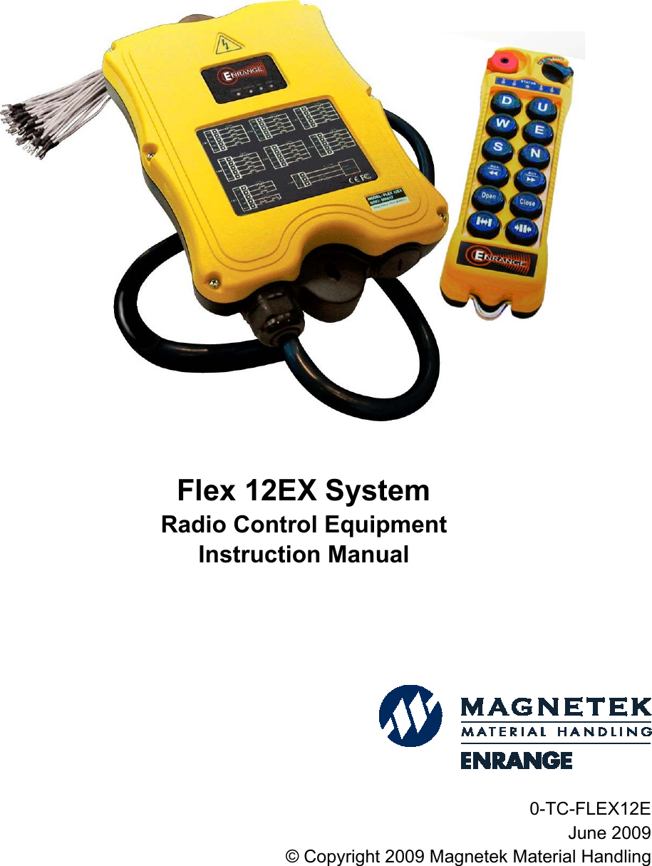
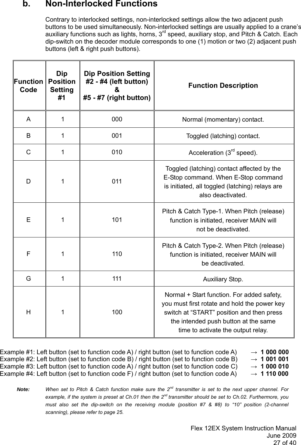
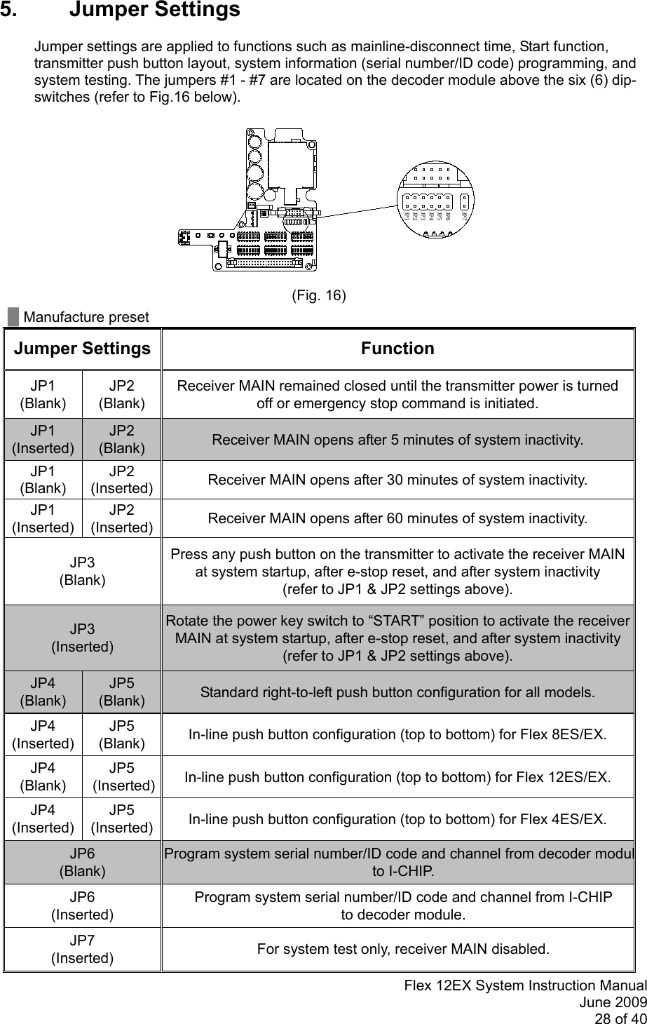
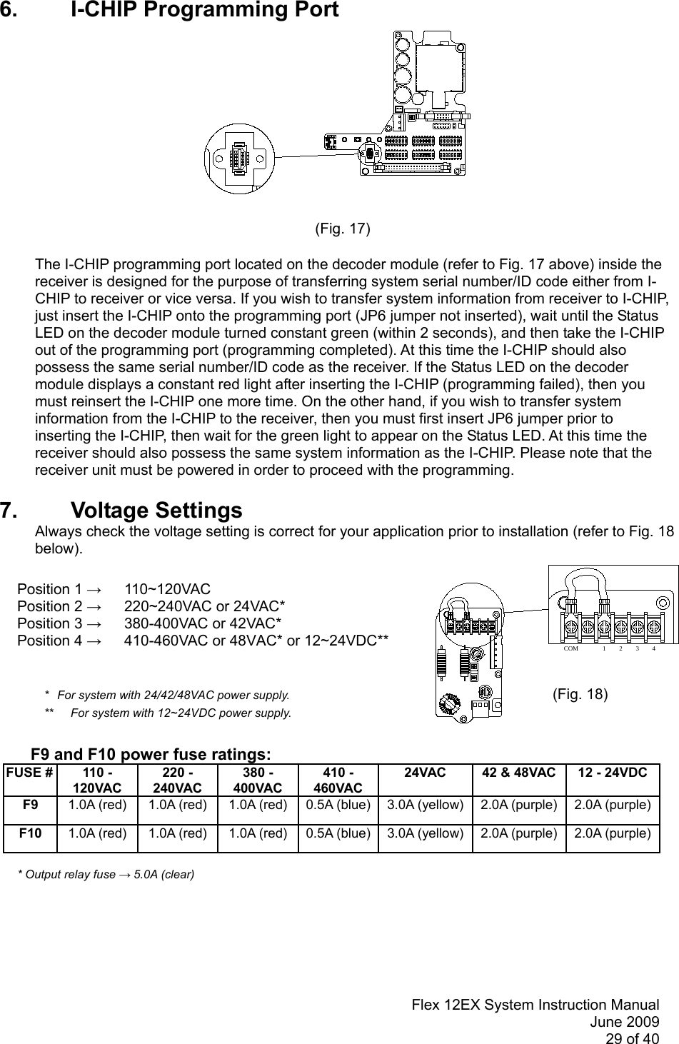
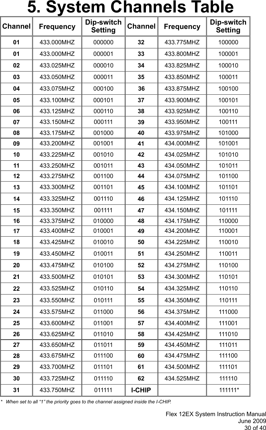
Magnetek FLEXSERIEST2 436 TO 440 MHz REMOTE CONTROL HANDHELD TRANSMITTER User Manual

Magnetek 436 TO 440 MHz REMOTE CONTROL HANDHELD TRANSMITTER Users Manual

Users Manual

Flex 12EX SystemRadio Control EquipmentInstruction Manual0-TC-FLEX12EJune 2009© Copyright 2009 Magnetek Material Handling
Service InformationYour New Radio SystemThank you for your purchase of Magnetek’s Enrange™ Flex EX radio remote control system.  Without adoubt, our Flex EX system is the ultimate solution for providing precise, undeterred, and safe control ofyour material.If your product ever needs modification or service, please contact one of our representatives at thefollowing locations:U.S. Service Information:For questions regarding service or technical information, contact:Enrange LLC#5 Four Coins DriveCanonsburg, PA 15317Telephone: 1.724.746.3313 x717Website: www.magnetekmh.comE-mail: info@magnetekmh.comFax Numbers:Main: 1.800.298.3503Sales: 1.262.783.3510Service: 1.262.783.3508Canada Service Information:2610 Dunwin DriveMississauga, OntarioL5L 1J5 CanadaTelephone: 1.800.792.7253Fax: 1.905.828.5707
Flex 12EX System Instruction ManualJune 20091 of 40Table of Contents          Page1. Introduction 32.  Radio Controlled Safety 43.  General System InformationA. Transmitter Handset1.  External Illustration (Standard Push Button Configuration) 52. Internal Illustration 6B. Receiver Unit 1. External Illustration 72. Internal Illustration  84. Function SettingsA. Transmitter Handset1.  System Channel Settings 92.  Push Button Functions with LED Displaysa. Standard Push Button Configuration (Transmitter Toggle) 10b. Standard Push Button Configuration (A/B Selector) 11-13c. Inline Push Button Configuration (Transmitter Toggle) 14d. Inline Push Button Configuration (A/B Selector) 15-173.  Channel Change via Push Buttons 184.  Program 4-digit Security Code 195.  I-CHIP    20B. Receiver Unit1.  System Channel Settings 212.  Output Relay Configurationsa. Output Relay Types 22b. Output Relay Action at 2nd Speed 22-23c. ON/OFF Push Button Function 23d. START/AUX Function 24e. Magnet ON/OFF Push Button Function 24f. Brake Function 24g. Momentary Contact 24h. Toggled Contact 24i. 3rd Speed Push Button Function 24j. Auxiliary STOP Push Button Function 25k. Pitch & Catch Function 253. Receiver Auto-Scanning Settings 254. Dip-Switch Settingsa. Interlocked Functions 26b. Non-Interlocked Functions 275. Jumpers Settings 286. I-CHIP Programming Port 297. Voltage Settings 29
Flex 12EX System Instruction ManualJune 20092 of 405.  System Channels Table 306. Receiver InstallationA.  Output Relay Contact Diagram 31B. Pre-Installation Precautions  32C. Step-by-Step Installation 32-33D. System Testing 337. Operating ProcedureA. Transmitter Operation1.  General Operating Procedure 34-352.  A/B Selector Push Button Operating Procedure 353. 3rd Speed Push Button Operating Procedure 354.  Pitch & Catch Operating Procedure 365.  Automatic Channel Scanning Operating Procedure 366.  Changing Transmitter Batteries 36B.  Status Light Indicators & Warnings1.  Transmitter STATUS Light Indication 372.  Receiver STATUS Light Indication 383.  Receiver SQ Light Indication 384.  Receiver POWER Light Indication 385.  Receiver COM Light Indication 38C.  Trouble Shooting Tips 398. System Specifications 40This portable transmitter with its antenna complies with FCC/IC RF exposure limits for generalpopulation / uncontrolled exposure.Compliance Statement (Part 15.19)This device complies with Part 15 of the FCC rules.Operation is subject to the following two conditions:1. This device may not cause harmful interference, and2. This device must accept any interference received, including interference that may causeundesired operation.Warning (Part 15.21)Changes or modifications not expressly approved by the party responsible for compliance could voidthe user’s authority to operate the equipment.
Flex 12EX System Instruction ManualJune 20093 of 401. IntroductionThe Flex radio remote control systems are designed for control of industrial equipment and machinery such asoverhead traveling cranes, jib cranes, gantry cranes, tower cranes, electric hoists, winches, monorails,conveyor belts, mining equipment and other material handling equipment where wireless control is preferred.Each Flex system consists of a transmitter handset and receiver unit. Other standard-equipped accessoriesinclude transmitter waist belt, spare transmitter power key, clear vinyl pouch, “AA” alkaline batteries, compassdirection decal sheet and user’s manual.List of notable features include:*62 user-programmable channels – Advanced synthesized RF controls with 62 built-in channels;there are no more fixed channel and fragile quartz crystals to break.*Automatic channel scanning receiver – No more hassle of climbing up the crane to change receiverchannels.*Over one million unique ID codes (20bit) – Each and every Flex system has its own unique IDcodes and serial number; no repeats.*Advanced controls – The Flex system utilizes advanced microprocessor controls with 32bit CRC andHamming Code, which provide ultra fast, safe, precise, and error-free encoding and decoding.*Unique I-CHIP design – The I-CHIP functions in a way that is very similar to SIM cards used onmobile phones, with the ability to transfer system information and settings from one transmitter toanother without the hassle of resetting the spares.*Reliable push buttons – The in-house designed push buttons with gold-plated contacts are rated formore than one million press cycles.*Low power consumption – Requires only two “AA” Alkaline batteries for more than 150 hours ofoperating time between replacements.*Ultra-durable nylon and fiberglass composite enclosures – Highly resistant to breakage anddeformation even in the most abusive environments.*Full compliance – All systems are fully compliant with the FCC Part-15 Rules, European Directives(Safety, EMC, R&TTE, and Machinery), and Industry Canada Specifications (IC).
Flex 12EX System Instruction ManualJune 20094 of 402. Radio Controlled SafetyFlex radio remote control systems should be operated by persons with sufficient amount of knowledge andskill in crane operation and safety. Persons being trained to operate a radio remote controlled crane shouldpossess the knowledge of all hazards peculiar to radio remote controlled crane operation, ability to judgedistance and moving objects, equipment capacity and radio remote controlled safety rules. Radio remotecontrolled cranes should not be operated by any person with insufficient eyesight/hearing, anysevere/debilitating illness, or under influence of drugs and medications that may cause loss of cranecontrol.Below are some general operating safety tips that should be strictly followed when operating a radio remotecontrolled crane.1.  Always check the transmitter handset for any damage that might inhibit proper crane operationprior to crane operation.2.  Always check if the red emergency stop button is working properly prior to crane operation.3.  Check the Status LED on the transmitter for any signs of low battery power (refer to page 37).4.  Check the Status LED on the transmitter for any signs of irregularities (refer to page 37).5.  The crane limit switches should be checked prior to crane operation or at the beginning of eachshift. When checking limit switches the hoist should be centered over an area free of personneland equipment.6.  If the power to the crane is removed, the operator should turn off the transmitter powerimmediately until the power to the crane is restored.7.  If the crane fails to respond properly to operator’s command the operator should stop operation,turn the transmitter power off, and then report the condition to their supervisor.8.  The transmitter power should be turned off after each use. If the transmitter handset is not in usealways turn the power off and store it in a safe or designated location. Never leave thetransmitter handset unattended in the working area.9.  Make sure the system is not set to the same channel as any other Flex systems in use within adistance of 300 meters (900 feet).10.  Never operate a crane or equipment with two transmitter handsets at the same time unless theyare programmed with “Pitch & Catch” function. For information on the “Pitch & Catch” feature,please refer to page 25 and page 36 of this manual.
Flex 12EX System Instruction ManualJune 20095 of 403. General System InformationA. TRANSMITTER HANDSET1. External Illustration (Standard Push ButtonConfiguration)(Fig. 01) (Fig. 02)1. Emergency Stop Button 8. Push Button #12 15. Strap Ring2. Removable Power Key Switch  9. Push Button #1 16. System Information3. Push Button #2 10. Push Button #3 17. System Channel4. Push Button #4 11. Push Button #5 18. Crane Number5. Push Button #6 12. Push Button #7 19. Battery Cover6. Push Button #8 13. Push Button #9 20. FCC Information7. Push Button #10 14. Push Button #11
Flex 12EX System Instruction ManualJune 20096 of 402. Internal Illustration(Fig. 03) (Fig. 04)1. Encoder Board 6. I-CHIP2. Arial Antenna 7. Function Dip-Switch3. Transmitting Module 8. Channel Dip-Switch4. Status LED Display 9. Battery Contact Mechanism5. Function LED Displays
Flex 12EX System Instruction ManualJune 20097 of 40B. RECEIVER UNIT1. External Illustration(Fig. 05)1. Shock Mount 6. COM LED Display2. Optional External Antenna (BNC) Jack 7. Output Contact Diagram3. Power LED Display 8. System Information4. Status LED Display 9. Cord Grip5. SQ LED Display
Flex 12EX System Instruction ManualJune 20098 of 402. Internal Illustration(Fig. 06)1. AC Line Filter 4. Decoder Module2. Power Transformer 5. Output Relay Board3. Receiving Module
Flex 12EX System Instruction ManualJune 20099 of 4071423 56 8CHANNEL71 423 56 84. Function SettingsA. TRANSMITTER HANDSET1. System Channel Settings(Fig. 07)             Set the transmitter channel by adjusting the channel dip-switch located on the backside of thetransmitter encoder board (refer to Fig. 07 above). Only the first six (6) positions are used forchannel programming (refer to Fig. 08 below). The system channels table located on page 30illustrates which dip-switch setting corresponds to which channel. Once the transmitter channelis altered make sure to change the receiver channel as well. The channel on both the transmitterand receiver must be identical in order for the system to work. To change the receiver channelplease refer to page 21. Example: Top slot → “1”Bottom slot → “0”(Fig. 08)The above dip-switch setting “1 0 0 1 0 0” corresponds to “channel 36” in the system channelstable on page 30.
Flex 12EX System Instruction ManualJune 200910 of 4052134 867FUNCTIONLED 1LED 2LED 3LED 42. Push Button Functions with LED Display SettingsA. Standard Push Button (Transmitter Toggle)Set transmitter toggle (latching output relay) function by adjusting the 8-position functiondip-switch located on the backside of the transmitter encoder board (refer to Fig. 09below). The LED 1 through LED 4 shown inside the shaded box (see below) illustrateswhich LED on the transmitter will light up when the designated push button (PB7 ~ PB12)is pressed.(Fig. 09)         DIP PB7 PB8 PB9 PB10 PB11 PB12100000000 Normal Normal Normal Normal Normal Normal200001001 Normal Normal Normal LED 4 Normal Normal300001010 Normal Normal LED 3 LED 4 Normal Normal400001011 Normal LED 2 LED 3 LED 4 Normal Normal500001100 LED 1 LED 2 LED 3 LED 4 Normal Normal600001101 Normal Normal Normal Normal Normal LED 4700001110 Normal Normal Normal Normal LED 3 LED 4800001111 Normal Normal Normal LED 2 LED 3 LED 4900010000 Normal Normal LED 1 LED 2 LED 3 LED 4* PB7…PB12 → Push button number* Normal → Normal momentary contact* LED 1…LED 4 → Transmitter toggled with designated LED Display
Flex 12EX System Instruction ManualJune 200911 of 40B. Standard Push Button Configuration (A/B Selector)There are four (4) different types of A/B selector sequences available on the Flex system.  Choose the one that is most suitable for your application.Type-A selector sequence : A+B → A → B → A+B …Type-B selector sequence : Off → A → B → Off → A → B …Type-C selector sequence : A → B → A+B → A → B → A+B …Type-D selector sequence : Off → A → B → A+B → Off → A → B → A+B …DIP PB7 PB8 PB9 PB10 PB11 PB1210 00101111 A/1&2 Normal Normal Normal Normal Normal11 00110000 B/1&2 Normal Normal Normal Normal Normal12 00110001 C/1&2 Normal Normal Normal Normal Normal13 00110010 D/1&2 Normal Normal Normal Normal Normal14 00110011 Normal A/3&4 Normal Normal Normal Normal15 00110100 Normal B/3&4 Normal Normal Normal Normal16 00110101 Normal C/3&4 Normal Normal Normal Normal17 00110110 Normal D/3&4 Normal Normal Normal Normal18 00110111 A/1&2 A/3&4 Normal Normal Normal Normal19 00111000 A/1&2 B/3&4 Normal Normal Normal Normal20 00111001 A/1&2 C/3&4 Normal Normal Normal Normal21 00111010 A/1&2 D/3&4 Normal Normal Normal Normal22 00111011 B/1&2 B/3&4 Normal Normal Normal Normal23 00111100 B/1&2 C/3&4 Normal Normal Normal Normal24 00111101 B/1&2 D/3&4 Normal Normal Normal Normal25 00111110 C/1&2 C/3&4 Normal Normal Normal Normal26 00111111 C/1&2 D/3&4 Normal Normal Normal Normal27 01000000 D/1&2 D/3&4 Normal Normal Normal Normal* PB7…PB12 → Push button number* Normal → Normal momentary contact* A/1&2…D/3&4 → A/B Selector type with designated LED Display (LED 1&2 or LED 3&4)
Flex 12EX System Instruction ManualJune 200912 of 40DIP PB7 PB8 PB9 PB10 PB11 PB1228 01000001 Normal Normal A/1&2 Normal Normal Normal29 01000010 Normal Normal B/1&2 Normal Normal Normal30 01000011 Normal Normal C/1&2 Normal Normal Normal31 01000100 Normal Normal D/1&2 Normal Normal Normal32 01000101 Normal Normal Normal A/3&4 Normal Normal33 01000110 Normal Normal Normal B/3&4 Normal Normal34 01000111 Normal Normal Normal C/3&4 Normal Normal35 01001000 Normal Normal Normal D/3&4 Normal Normal36 01001001 Normal Normal A/1&2 A/3&4 Normal Normal37 01001010 Normal Normal A/1&2 B/3&4 Normal Normal38 01001011 Normal Normal A/1&2 C/3&4 Normal Normal39 01001100 Normal Normal A/1&2 D/3&4 Normal Normal40 01001101 Normal Normal B/1&2 B/3&4 Normal Normal41 01001110 Normal Normal B/1&2 C/3&4 Normal Normal42 01001111 Normal Normal B/1&2 D/3&4 Normal Normal43 01010000 Normal Normal C/1&2 C/3&4 Normal Normal44 01010001 Normal Normal C/1&2 D/3&4 Normal Normal45 01010010 Normal Normal D/1&2 D/3&4 Normal Normal* PB7…PB12 → Push button number* Normal → Normal momentary contact* A/1&2…D/3&4 → A/B Selector type with designated LED Display (LED 1&2 or LED 3&4)
Flex 12EX System Instruction ManualJune 200913 of 40DIP PB7 PB8 PB9 PB10 PB11 PB1246 01010011 Normal Normal Normal Normal A/1&2 Normal47 01010100 Normal Normal Normal Normal B/1&2 Normal48 01010101 Normal Normal Normal Normal C/1&2 Normal49 01010110 Normal Normal Normal Normal D/1&2 Normal50 01010111 Normal Normal Normal Normal Normal A/3&451 01011000 Normal Normal Normal Normal Normal B/3&452 01011001 Normal Normal Normal Normal Normal C/3&453 01011010 Normal Normal Normal Normal Normal D/3&454 01011011 Normal Normal Normal Normal A/1&2 A/3&455 01011100 Normal Normal Normal Normal A/1&2 B/3&456 01011101 Normal Normal Normal Normal A/1&2 C/3&457 01011110 Normal Normal Normal Normal A/1&2 D/3&458 01011111 Normal Normal Normal Normal B/1&2 B/3&459 01100000 Normal Normal Normal Normal B/1&2 C/3&460 01100001 Normal Normal Normal Normal B/1&2 D/3&461 01100010 Normal Normal Normal Normal C/1&2 C/3&462 01100011 Normal Normal Normal Normal C/1&2 D/3&463 01100100 Normal Normal Normal Normal D/1&2 D/3&4* PB7…PB12 → Push button number* Normal → Normal momentary contact* A/1&2…D/3&4 → A/B Selector type with designated LED Display (LED 1&2 or LED 3&4)
Flex 12EX System Instruction ManualJune 200914 of 40C. Inline Push Button Configuration (Transmitter Toggle)The push button arrangement for inline push button setup starts from top to bottom andthen from right column to left column (refer to Fig. 10 below). To set inline push buttonconfiguration please refer to JP4 and JP5 jumpers setting on page 28. With inline pushbuttons configuration, PB1 & PB2 still corresponds to output relay K1 - K4; PB3 & PB4corresponds to relay K5 - K8; etc…(Fig. 10)DIP PB7 PB8 PB9 PB10 PB11 PB1264 00000000 Normal Normal Normal Normal Normal Normal65 00000101 Normal Normal Normal LED 4 Normal Normal66 00010100 Normal Normal LED 3 LED 4 Normal Normal67 00010101 Normal LED 2 LED 3 LED 4 Normal Normal68 00010110 LED 1 LED 2 LED 3 LED 4 Normal Normal69 00001001 Normal Normal Normal Normal LED 4 Normal70 00010111 Normal Normal Normal LED 3 LED 4 Normal71 00011000 Normal Normal LED 2 LED 3 LED 4 Normal72 00011001 Normal LED 1 LED 2 LED 3 LED 4 Normal73 00001101 Normal Normal Normal Normal Normal LED 474 00011010 Normal Normal Normal Normal LED 3 LED 475 00011011 Normal Normal Normal LED 2 LED 3 LED 476 00011100 Normal Normal LED 1 LED 2 LED 3 LED 4* PB7…PB12 → Push button number* Normal → Normal momentary contact* LED 1…LED 4 → Transmitter toggled with designated LED Display
Flex 12EX System Instruction ManualJune 200915 of 40D. Inline Push Button Configuration (A/B Selector)There are four (4) different types of A/B selector sequences available on the Flex system.  Choose the one that is most suitable for your application.Type-A selector sequence : A+B → A → B → A+B …Type-B selector sequence : Off → A → B → Off → A → B …Type-C selector sequence : A → B → A+B → A → B → A+B …Type-D selector sequence : Off → A → B → A+B → Off → A → B → A+B …DIP PB9 PB10 PB11 PB1277 01110011 A/1&2 Normal Normal Normal78 01110100 B/1&2 Normal Normal Normal79 01110101 C/1&2 Normal Normal Normal80 01110110 D/1&2 Normal Normal Normal81 00110011 Normal A/3&4 Normal Normal82 00110100 Normal B/3&4 Normal Normal83 00110101 Normal C/3&4 Normal Normal84 00110110 Normal D/3&4 Normal Normal85 01110111 A/1&2 A/3&4 Normal Normal86 01111000 A/1&2 B/3&4 Normal Normal87 01111001 A/1&2 C/3&4 Normal Normal88 01111010 A/1&2 D/3&4 Normal Normal89 01111011 B/1&2 B/3&4 Normal Normal90 01111100 B/1&2 C/3&4 Normal Normal91 01111101 B/1&2 D/3&4 Normal Normal92 01111110 C/1&2 C/3&4 Normal Normal93 01111111 C/1&2 D/3&4 Normal Normal94 10000000 D/1&2 D/3&4 Normal Normal* PB7…PB12 → Push button number* Normal → Normal momentary contact* A/1&2…D/3&4 → A/B Selector type with designated LED Display (LED 1&2 or LED 3&4)
Flex 12EX System Instruction ManualJune 200916 of 40DIP PB9 PB10 PB11 PB1295 10000001 Normal A/1&2 Normal Normal96 10000010 Normal B/1&2 Normal Normal97 10000011 Normal C/1&2 Normal Normal98 10000100 Normal D/1&2 Normal Normal99 01000101 Normal Normal A/3&4 Normal100 01000110 Normal Normal B/3&4 Normal101 01000111 Normal Normal C/3&4 Normal102 01001000 Normal Normal D/3&4 Normal103 10000101 Normal A/1&2 A/3&4 Normal104 10000110 Normal A/1&2 B/3&4 Normal105 10000111 Normal A/1&2 C/3&4 Normal106 10001000 Normal A/1&2 D/3&4 Normal107 10001001 Normal B/1&2 B/3&4 Normal108 10001010 Normal B/1&2 C/3&4 Normal109 10001011 Normal B/1&2 D/3&4 Normal110 10001100 Normal C/1&2 C/3&4 Normal111 10001101 Normal C/1&2 D/3&4 Normal112 10001110 Normal D/1&2 D/3&4 Normal* PB7…PB12 → Push button number* Normal → Normal momentary contact* A/1&2…D/3&4 → A/B Selector type with designated LED Display (LED 1&2 or LED 3&4)
Flex 12EX System Instruction ManualJune 200917 of 40DIP PB9 PB10 PB11 PB12113 10001111 Normal Normal A/1&2 Normal114 10010000 Normal Normal B/1&2 Normal115 10010001 Normal Normal C/1&2 Normal116 10010010 Normal Normal D/1&2 Normal117 01010111 Normal Normal Normal A/3&4118 01011000 Normal Normal Normal B/3&4119 01011001 Normal Normal Normal C/3&4120 01011010 Normal Normal Normal D/3&4121 10010011 Normal Normal A/1&2 A/3&4122 10010100 Normal Normal A/1&2 B/3&4123 10010101 Normal Normal A/1&2 C/3&4124 10010110 Normal Normal A/1&2 D/3&4125 10010111 Normal Normal B/1&2 B/3&4126 10011000 Normal Normal B/1&2 C/3&4127 10011001 Normal Normal B/1&2 D/3&4128 10011010 Normal Normal C/1&2 C/3&4129 10011011 Normal Normal C/1&2 D/3&4130 10011100 Normal Normal D/1&2 D/3&4* PB7…PB12 → Push button number* Normal → Normal momentary contact* A/1&2…D/3&4 → A/B Selector type with designated LED Display (LED 1&2 or LED 3&4)
Flex 12EX System Instruction ManualJune 200918 of 403. Channel Change via Push ButtonsOther than CHANNEL dip-switch on the encoder board, the transmitter channel can also bechanged directly on the push buttons. Please refer to the instruction below on how to change thetransmitter channel via push buttons.a. Press and hold PB1, PB2 and PB3 and rotate the power key to START position at the sametime. A series of green and red blinks will appear on the Status LED showing the currentchannel setting. A green blink represents the tens (+10) and a red blink represents the units(+1).Examples: 2 green blinks followed by 5 red blinks represents channel 25.6 red blinks represents channel 06.+b. Select a new channel by pressing PB1 and PB2 on the transmitter. Press PB1 to incrementthe units (+1) and PB2 to increment the tens (+10).Examples:  Press PB2 two times and then PB1 four times will give you channel 24.Press PB1 nine times with give you channel 09.c. When finished, the newly selected channel will appear on the Status LED via a series ofgreen and red blinks again.d. Exit the channel programming by turning off the transmitter power.e. Make sure the receiver channel is set identical to the transmitter. Please refer to page 21 andpage 36 on how to change receiver channel.f. Please note that when the CHANNEL dip-switch inside the transmitter is changed, the prioritywill revert back to the new channel set on the CHANNEL dip-switch.g. Please note that when channel is set beyond channel 62 via PB1 and PB2 (i.e. channel 63,68, 88, etc…), the system will recognize it as channel 62.
Flex 12EX System Instruction ManualJune 200919 of 404. Program 4-Digit Security CodePrior to rotating the transmitter power key-switch to the START position to begin operation, youmust first enter a 4-digit security code in order to proceed further. When this 4-digit security code isinput correctly, a green light will appear on the Status LED. Please refer to the instruction below onhow to program the 4-digit security code.a. Press and hold PB1, PB2, PB3 and PB4 and rotate the power key to START position at thesame time. +b. A constant orange light will appear on the Status LED telling you that you are in the securitycode programming mode.c. For newly purchased system with the security code function deactivated (default setting),press PB1 four times (1111) to activate the security code function. At this time the Status LEDon the transmitter will blink orange slowly telling you that the 4 digits entered is correct. Thenselect your own 4-digit security code by pressing PB1, PB2, PB3 or PB4 on the transmitter(four presses randomly). At this time fast orange blinks are displayed on the Status LEDtelling you to reconfirm the 4-digit security code you have just entered. A green light willappear once you have re-entered the same 4-digit security code again (programmingcompleted). If a red light is shown on the Status LED after you have re-entered the securitycode (incorrect input), then you must reset the transmitter power and then repeat steps a, band c again.Steps: Press and hold PB1-PB4 and rotate power key to START position → constant orange→ press PB1 four times (for new systems) or 4-digit security code → slow orange blinks →enter the new 4-digit security code → fast orange blinks → re-enter the same 4-digit securitycode again → green light.d. If you wish to cancel the security code function, then repeat steps a, b, and c above andpress PB1 four times as your new security code (security code function disabled).e. If you do not remember the 4-digit security code, then you must contact your dealer ordistributor for further assistance.
Flex 12EX System Instruction ManualJune 200920 of 405. I-CHIPThe I-CHIP functions in a way that is very similar to a SIM card inside a mobile phone, whichstores system information such as your telephone number, account number, phone book andother settings. The I-CHIP works exactly the same way, as it stores information such as systemserial number/ID code, channel and push button configurations.When replacing a transmitter handset, just take the I-CHIP out of the old transmitter and install itinto the new one (refer to Fig. 11 below). For a complete information transfer, make sure both theChannel and Function dip-switch is set to all “1”. If both dip-switches are set to all “1”, then thetransmitter will operate according to the push button configurations and channel stored inside theI-CHIP. If both the Channel and Function dip-switch is set to other values other than all “1”, thenthe transmitter will operate according to the channel and push button configurations set on thesetwo dip-switches, not the ones stored inside the I-CHIP. Every time the settings on these two dip-switches are changed, the new settings will be stored into the I-CHIP automatically. In this casethe previous channel and push button configurations stored inside the I-CHIP will be erased andbe replaced by the new settings.For safety purposes, the system serial number/ID code stored inside the I-CHIP cannot bechanged directly on the transmitter encoder board. Only channels and push buttonconfigurations can be changed directly on the encoder board via Channel and Function dip-switches. There are only two ways that you can change a transmitter serial number/ID code: viathe I-CHIP programming port located on the decoder module inside the receiver unit, pleaserefer to page 29 on how to program the I-CHIP (serial number/ID code) via receiver unit; or viaan external I-CHIP programmer or duplicator unit available from the factory. Please ask yourlocal dealers for assistance if your system requires serial number/ID code adjustments.(Fig. 11)
Flex 12EX System Instruction ManualJune 200921 of 4071 423 56 8INTEXT12356847B. RECEIVER UNIT1. System Channel Settings(Fig. 12)Even though the Flex system is equipped with an automatic channel scanning receiver, the usercan also set the receiver channel manually. Please refer to page 36 on how the automaticchannel scanning receiver works.Set the receiver channel by adjusting the channel dip-switch located on the receiver module(refer to Fig. 12 above), only the first six (6) positions are used for channel programming (refer toFig. 13 below). The system channels table located on page 30 illustrates which dip-switch settingcorresponds to which channel. Once the receiver channel is altered make sure to change thetransmitter channel as well. The channel on both the transmitter and receiver must be identical inorder for the system to work. To change the transmitter channel please refer to page 9. Example: Top slot → “1”Bottom slot → “0”(Fig. 13)The above dip-switch setting “1 0 0 1 0 0” corresponds to “channel 36” in the system channelstable on page 30.
Flex 12EX System Instruction ManualJune 200922 of 40F1 R1 F/R2F1 F2R1 R2F1 F/R2R1 R1F1 F/R22. Output Relay Configurationsa. Output Relay Types1. Three (3) output relays per motion – shared 2nd speed output relayOutput relays with Forward 1st speed (F1), Reverse 1st speed (R1) andForward/Reverse 2nd speed (F/R2). Forward and Reverse 2nd speed (F/R2) share thesame output relay.2. Four (4) output relays per motion – separate 1st and 2nd speed outputrelaysOutput relays with Forward 1st speed (F1), Reverse 1st speed (R1), Forward 2nd  speed(F2) and Reverse 2nd speed (R2). Forward and Reverse 2nd speed with separate outputrelays.b. Output Relay Actions at 2nd Speed1. 3-output relays configuration with Closed/Closed contact at 2ndspeedAt 2nd speed, both 1st speed (F1 or R1) and 2nd speed (F/R2) output relays areclosed (refer to page 26 on how to set to this function).      Forward 1st speed push button pressed                 Forward 2nd speed push button pressed  ↓↓
Flex 12EX System Instruction ManualJune 200923 of 40F1 R1 F2 R2R2F2R1F1ONOFFR2F2R1F1 R2F2R1F12. 4-output relays configuration with Opened/Closed contact at 2ndspeedAt 2nd speed, only the 2nd speed (F2 or R2) output relay is closed (refer to page 26 onhow to set to this function).      Forward 1st speed push button pressed             Forward 2nd speed push button pressed  ↓ ↓3. 4-output relays configuration with Closed/Closed contact at 2ndspeedAt 2nd speed, both 1st speed (F1 or R1) and 2nd speed (F2 or R2) output relays areclosed (refer to page 26 on how to set to this function).      Forward 1st speed push button pressed             Forward 2nd speed push button pressed  ↓   ↓c. ON/OFF Push Button FunctionThe user can set any of the two adjacent push buttons on the transmitter to behave like amechanical ON & OFF rocker switch (refer to page 26 on how to set to this function). When“On” output relay is closed (“On” push button pressed), the “Off” output relay will openautomatically, or vice versa.
Flex 12EX System Instruction ManualJune 200924 of 40OFF3rdSPEEDd. START/AUX FunctionAfter initiating the START function the Start position will become an auxiliary function withmomentary contact. For auxiliary applications such as a horn or a buzzer, please connect it tothe FUNC output relay (wire #6) located inside the receiver unit.e. Magnet ON/OFF Push Button FunctionThe user can set any of the two adjacent push buttons on the transmitter to control amagnet. To activate the magnet just press the push button with the Magnet symbol. Todeactivate the magnet, for safety purpose, you must first press and hold the Magnet pushbutton and then press the OFF push button. Pressing the OFF push button by itself can notdeactivate the magnet (refer to page 26 on how to set to this function).f. Brake FunctionWhen the transmitter push button is released from 2nd speed up to 1st speed, both 1st and 2ndspeed output relays will open for up to 1.0 second and then with 1st speed output relay closedthereafter (refer to page 26 on how to set to this function).g. Momentary ContactWhen push button is released the output relay corresponds to that push button will open(refer to page 27 on how to set to this function). This type of contact is usually applies toexternal application such as horns or buzzers.h. Toggled ContactWhen the push button is released the output relay corresponds to that push button willremain closed (maintained contact) until the next time the user presses the same pushbutton again (refer to page 27 on how to set to this function). This type of contact is usuallyapplied to external application such as lights.i. 3rd Speed Push Button FunctionThis function allows the crane to travel an additional step beyond 2nd speed. For example, ifthe operator is pressing the “UP” push button down to 2nd speed, pressing the 3rd speed pushbutton (with “UP” push button still hold at 2nd speed) will toggle between the 2nd speed and 3rdspeed (refer to page 27 on how to set to this function).
Flex 12EX System Instruction ManualJune 200925 of 40AuxSTOP41 32 65 874132 65 874231785641 2 3 65 78j. Auxiliary STOP Push Button FunctionThe auxiliary STOP function acts as a 2nd emergency stop button. Other than byemergency stop button and transmitter power key switch, the receiver MAIN is alsodeactivated when this auxiliary stop push button is pressed (refer to page 27 on how toset to this function).k. Pitch & Catch FunctionThis function allows two operators to control one crane from opposite ends of a cross orlong travel (refer to page 27 on how to set to this function). When set to “Pitch & Catch”make sure the 2nd transmitter is set to the next upper channel (channel X*+1). For example,if the system is preset at “Ch.01” then the channel of the 2nd transmitter should be set to“Ch.02”. Furthermore, the dip-switch position #7 and #8 on the receiving module should beset to “01”, this will allow the receiver to scan only Ch.01 and Ch.02 (please refer to theillustration below). On the other hand, since there are only 62 available channels on theFlex system, the system preset at channel 62 is ineffective because the 2nd transmitter cannot be set to Ch.63. If your system is preset at Ch.62 make sure to change it to anotherchannel.3. Receiver Auto-Scanning SettingsReceiver Channel Dip-switch↓(1) →Scanning all 62 channels (manufacture preset)For standard operation(2) →Single fixed channel (channel X*) Auto scanning function disabled(3) →Scanning 2 channels only (channel X*, channel X*+1)For Pitch & Catch, Tandem, and Random Access operation with2 receivers(4) →Scanning 3 channels only (channel X*, channel X*+1, channel X*+2)For Random Access operation with 3 receivers* Channel X → Channel set on the receiving moduleExample:  If the first 6 dip-switch positions on the receiving module is set to Ch.01(“000000” or “000001”), when set to 2-channel scanning (type-3 above), thenthe receiver will only scan Ch.01 and Ch.02.
Flex 12EX System Instruction ManualJune 200926 of 40RELAY FUNCTIONS1 324 756 84. Dip-Switch Settingsa. Interlocked FunctionsInterlocked means the two adjacent push buttons can not be activated simultaneously asthey will cancel each other out. Interlocked settings are usually applied to a crane’s forwardand reverse motions. Each dip-switch on the decoder module corresponds to one (1)motion or two (2) adjacent push buttons (refer to Fig. 14 & 15 below). Only the first seven(7) dip-switch positions are used (counting from left to right).  The 8th dip-switch position(far right) is not used.  (Fig. 14) (Fig. 15)▇ Manufacture presetDipSettings Function Descriptions # of RelaysUsed0000000 Normal (single speed only, F2 & R2 relays not used) 20000001 Closed/Closed Relay Action at 2nd Speed (separate 2nd speedrelay) 40000010 Closed/Closed Relay Action at 2nd Speed (shared 2nd speedrelay) 30000011 Opened/Closed Relay Action at 2nd Speed (separate 2nd speedrelay) 40000110 On (right button) & Off (left button) 20001000 On & Off affected by the e-stop command. When E-stopcommand is initiated, the Off relay is activated. 20001001On + Start / Off + Start -- Prior to pressing the button you mustfirst rotate and hold the power key switch at START position toactivate On or Off relays.20001010 FWD/REV toggled (latched). 20001011 FWD/REV toggled (latched) and affected by the E-stopcommand. 20000111 Safety Magnet On & Off 20100001 Closed/Closed + Brake 40100010 Closed/Closed Relay Action + Brake 30100011 Opened/Closed Relay Action + Brake 4
Flex 12EX System Instruction ManualJune 200927 of 40b. Non-Interlocked FunctionsContrary to interlocked settings, non-interlocked settings allow the two adjacent pushbuttons to be used simultaneously. Non-interlocked settings are usually applied to a crane’sauxiliary functions such as lights, horns, 3rd speed, auxiliary stop, and Pitch & Catch. Eachdip-switch on the decoder module corresponds to one (1) motion or two (2) adjacent pushbuttons (left & right push buttons).FunctionCodeDipPositionSetting#1Dip Position Setting#2 - #4 (left button)&#5 - #7 (right button)Function DescriptionA 1 000 Normal (momentary) contact.B 1 001 Toggled (latching) contact.C 1 010 Acceleration (3rd speed).D1 011Toggled (latching) contact affected by theE-Stop command. When E-Stop commandis initiated, all toggled (latching) relays arealso deactivated.E 1 101Pitch & Catch Type-1. When Pitch (release)function is initiated, receiver MAIN willnot be deactivated.F1 110Pitch & Catch Type-2. When Pitch (release)function is initiated, receiver MAIN willbe deactivated.G1 111 Auxiliary Stop.H 1 100Normal + Start function. For added safety,you must first rotate and hold the power keyswitch at “START” position and then pressthe intended push button at the sametime to activate the output relay.Example #1: Left button (set to function code A) / right button (set to function code A)  →  1 000 000Example #2: Left button (set to function code B) / right button (set to function code B) →  1 001 001Example #3: Left button (set to function code A) / right button (set to function code C) →  1 000 010Example #4: Left button (set to function code F) / right button (set to function code A) →  1 110 000Note: When set to Pitch & Catch function make sure the 2nd transmitter is set to the next upper channel. Forexample, if the system is preset at Ch.01 then the 2nd  transmitter should be set to Ch.02. Furthermore, youmust also set the dip-switch on the receiving module (position #7 & #8) to “10” position (2-channelscanning), please refer to page 25.
Flex 12EX System Instruction ManualJune 200928 of 40JP1JP2JP3JP4JP5JP6JP75. Jumper SettingsJumper settings are applied to functions such as mainline-disconnect time, Start function,transmitter push button layout, system information (serial number/ID code) programming, andsystem testing. The jumpers #1 - #7 are located on the decoder module above the six (6) dip-switches (refer to Fig.16 below).(Fig. 16)▇ Manufacture presetJumper Settings FunctionJP1(Blank)JP2(Blank)Receiver MAIN remained closed until the transmitter power is turnedoff or emergency stop command is initiated.JP1(Inserted)JP2(Blank) Receiver MAIN opens after 5 minutes of system inactivity.JP1(Blank)JP2(Inserted) Receiver MAIN opens after 30 minutes of system inactivity.JP1(Inserted)JP2(Inserted) Receiver MAIN opens after 60 minutes of system inactivity.JP3(Blank)Press any push button on the transmitter to activate the receiver MAINat system startup, after e-stop reset, and after system inactivity(refer to JP1 & JP2 settings above).JP3(Inserted)Rotate the power key switch to “START” position to activate the receiverMAIN at system startup, after e-stop reset, and after system inactivity(refer to JP1 & JP2 settings above).JP4(Blank)JP5(Blank) Standard right-to-left push button configuration for all models.JP4(Inserted)JP5(Blank) In-line push button configuration (top to bottom) for Flex 8ES/EX.JP4(Blank)JP5 (Inserted) In-line push button configuration (top to bottom) for Flex 12ES/EX.JP4(Inserted)JP5(Inserted) In-line push button configuration (top to bottom) for Flex 4ES/EX.JP6(Blank)Program system serial number/ID code and channel from decoder modulto I-CHIP.JP6(Inserted)Program system serial number/ID code and channel from I-CHIPto decoder module.JP7(Inserted) For system test only, receiver MAIN disabled.
Flex 12EX System Instruction ManualJune 200929 of 40COM 12346. I-CHIP Programming Port(Fig. 17)The I-CHIP programming port located on the decoder module (refer to Fig. 17 above) inside thereceiver is designed for the purpose of transferring system serial number/ID code either from I-CHIP to receiver or vice versa. If you wish to transfer system information from receiver to I-CHIP,just insert the I-CHIP onto the programming port (JP6 jumper not inserted), wait until the StatusLED on the decoder module turned constant green (within 2 seconds), and then take the I-CHIPout of the programming port (programming completed). At this time the I-CHIP should alsopossess the same serial number/ID code as the receiver. If the Status LED on the decodermodule displays a constant red light after inserting the I-CHIP (programming failed), then youmust reinsert the I-CHIP one more time. On the other hand, if you wish to transfer systeminformation from the I-CHIP to the receiver, then you must first insert JP6 jumper prior toinserting the I-CHIP, then wait for the green light to appear on the Status LED. At this time thereceiver should also possess the same system information as the I-CHIP. Please note that thereceiver unit must be powered in order to proceed with the programming.7. Voltage SettingsAlways check the voltage setting is correct for your application prior to installation (refer to Fig. 18below).Position 1 → 110~120VACPosition 2 →220~240VAC or 24VAC*Position 3 →  380-400VAC or 42VAC*Position 4 →  410-460VAC or 48VAC* or 12~24VDC***   For system with 24/42/48VAC power supply. (Fig. 18)** For system with 12~24VDC power supply.    F9 and F10 power fuse ratings:FUSE # 110 -120VAC220 -240VAC380 -400VAC410 -460VAC24VAC 42 & 48VAC 12 - 24VDCF9 1.0A (red) 1.0A (red) 1.0A (red) 0.5A (blue) 3.0A (yellow) 2.0A (purple) 2.0A (purple)F10 1.0A (red) 1.0A (red) 1.0A (red) 0.5A (blue) 3.0A (yellow) 2.0A (purple) 2.0A (purple)* Output relay fuse → 5.0A (clear)
Flex 12EX System Instruction ManualJune 200930 of 405. System Channels TableChannel Frequency Dip-switchSetting Channel Frequency Dip-switchSetting01 433.000MHZ 000000 32 433.775MHZ 10000001 433.000MHZ 000001 33 433.800MHZ 10000102 433.025MHZ 000010 34 433.825MHZ 10001003 433.050MHZ 000011 35 433.850MHZ 10001104 433.075MHZ 000100 36 433.875MHZ 10010005 433.100MHZ 000101 37 433.900MHZ 10010106 433.125MHZ 000110 38 433.925MHZ 10011007 433.150MHZ 000111 39 433.950MHZ 10011108 433.175MHZ 001000 40 433.975MHZ 10100009 433.200MHZ 001001 41 434.000MHZ 10100110 433.225MHZ 001010 42 434.025MHZ 10101011 433.250MHZ 001011 43 434.050MHZ 10101112 433.275MHZ 001100 44 434.075MHZ 10110013 433.300MHZ 001101 45 434.100MHZ 10110114 433.325MHZ 001110 46 434.125MHZ 10111015 433.350MHZ 001111 47 434.150MHZ 10111116 433.375MHZ 010000 48 434.175MHZ 11000017 433.400MHZ 010001 49 434.200MHZ 11000118 433.425MHZ 010010 50 434.225MHZ 11001019 433.450MHZ 010011 51 434.250MHZ 11001120 433.475MHZ 010100 52 434.275MHZ 11010021 433.500MHZ 010101 53 434.300MHZ 11010122 433.525MHZ 010110 54 434.325MHZ 11011023 433.550MHZ 010111 55 434.350MHZ 11011124 433.575MHZ 011000 56 434.375MHZ 11100025 433.600MHZ 011001 57 434.400MHZ 11100126 433.625MHZ 011010 58 434.425MHZ 11101027 433.650MHZ 011011 59 434.450MHZ 11101128 433.675MHZ 011100 60 434.475MHZ 11110029 433.700MHZ 011101 61 434.500MHZ 11110130 433.725MHZ 011110 62 434.525MHZ 11111031 433.750MHZ 011111 I-CHIP  111111** When set to all “1” the priority goes to the channel assigned inside the I-CHIP.
Flex 12EX System Instruction ManualJune 200931 of 406. Receiver InstallationA. OUTPUT RELAY CONTACT DIAGRAM*  For 3-relay (shared 2nd speed) and 4-relay (separate 2nd speed) configuration please refer to pages22-26.*  For 4-relay closed/closed and 4-relay opened/closed relay configuration please refer to pages22-26.*  For different voltage settings please refer to page 29.* For F9 and F10 power fuse ratings please refer to page 29.* For 12 - 24VDC power supply, wire #1 corresponds to the negative charge (-) and wire #3corresponds to the positive charge (+).  Wire #2 is for GROUND.
Flex 12EX System Instruction ManualJune 200932 of 40B. PRE-INSTALLATION PRECAUTIONS1. Make sure the transmitter and receiver have identical serial number/ID codes and channels.2. Make sure the receiver is not set to the same channel as any other systems in use in the surrounding area.3. Make sure that the crane or equipment is working properly prior to installation.4. Make sure the power source to the receiver is set correctly.5. Switch off the main power source to the crane or equipment prior to installation.C. STEP-BY-STEP INSTALLATION(Fig. 19)1. For best reception the location of the receiver should be visible to the operator at all time.2. The location selected should not be exposed to high levels of electric noise. Mounting thereceiver next to an unshielded variable frequency drive may cause minor interference. Alwayslocate the receiver as far away from variable frequency drive as possible.
Flex 12EX System Instruction ManualJune 200933 of 40432 mmControlPanel3. Ensure the selected location has adequate space to accommodate thereceiver (refer to Fig. 19 on page 32). If an external antenna is used, toavoid the possibility of antenna damage always locate the receiverwhere the antenna is free from any obstacles from all directions (refer todiagram at right).4. When installing an external antenna you must connect the SMA jacklocated inside the receiver and make sure to set the jumper to “EXT”position (refer to diagram below).5. For better reception, make sure the receiver is in an upright position.6. Drill two holes (10mm in diameter) on the control panel or location where the receiver is to beinstalled (refer to Fig. 19 on page 32).7. Make sure the two bolts are tightened after installation.8. For system wiring please refer to page 31.D. SYSTEM TESTING1. Turn on the power source to the receiver and test the MAIN relay output by pressing the redemergency stop button and observe that it properly opens and closes the mainline disconnectcontactor.2. Test the operation of each function to ensure it corresponds to the transmitter direction labels or thependant it is replacing.3. Test the limit switches (if any) to see if they are working properly.4. If your new remote control is replacing an existing pendant, make sure it is completelydisconnected and placed in a safe location to prevent unwanted control commands.
Flex 12EX System Instruction ManualJune 200934 of 407. Operating ProcedureA. TRANSMITTER OPERATION1. General Operating Procedurea. Reset the red emergency stop button located on the top left hand side of the transmitter handset by rotating it either clockwise or counter clockwise.  The red button will pop up.b. Turn on the transmitter power by inserting the black-colored key into the power key slotlocated on the top right hand side of the transmitter handset and rotate it clockwise to “On”position.c. After turning on the transmitter power, check the Status LED on the transmitter handset for anysign of system irregularities (refer to “Status Light Indicators & Warnings” on page 37). If thesystem is normal the Status LED will light up green for two (2) seconds.d. If there are no signs of any system irregularities, then rotate the power key further clockwiseto “Start” position for up to 2 seconds.  This will activate the receiver MAIN (depends on JP3setting on page 28). Thereafter, the same “Start” position will become an auxiliary functionwith momentary contact (refer to page 24).e. Now press any push button on the transmitter handset to operate the crane or equipment.
Flex 12EX System Instruction ManualJune 200935 of 40AB3rdSPEEDDuring transmitter inactivity (push buttons not pressed), the transmitter will automaticallyswitch to standby mode, with an orange blink on the Status LED every 4-second interval.f. In case of an emergency, pressing down on the red emergency stop button willimmediately disconnect the receiver mainline (Status LED blinks red). To reset theemergency stop button just rotate the red button either clockwise or counter-clockwise; itwill pop up. When the green light appears, rotate the power key to “Start” position toresume operation (depends on JP3 setting on page 28).g. After 5 minutes of inactivity (push button not pressed) the receiver MAIN will bedisconnected temporarily (depends on JP1 & JP2 settings on page 28). To resumeoperation just rotate the power key switch to START position to reconnect the receiverMAIN.h. Turn off the transmitter power by rotating the power key counter-clockwise to “Off” position; itwill disconnect the transmitter power and the receiver MAIN altogether. Turn it furthercounter-clockwise to release the key.2. A/B Selector Push Button Operating ProcedurePressing the “Select A/B” push button will toggle between output relay A, B, A+B respectively.There are 4 different types of Select A/B sequences available; please refer to page 11~13 forinstructions on how to set Select A/B functions.3. 3rd Speed Push Button Operating ProcedureWhen a push button is held at 2nd speed, pressing the 3rd Speed push button one time willactivate the 3rd speed output relay (toggled). If the operator wants 2nd speed again, just pressthe 3rd Speed push button one more time.
Flex 12EX System Instruction ManualJune 200936 of 40ONOFFCATCHCATCHCATCHPITCHPITCH124. Pitch & Catch Operating Procedure To release control of the crane, press the “Pitch” push button. To take over control of the crane,rotate the power key switch to “Catch” position for up to 2 seconds. The 2nd operator can nottake control of the crane unless the 1st operator presses the “Pitch” push button (2.0 seconds).If the operator unintentionally presses the “Pitch” push button during operation, just rotate thepower key to “Catch” position for up to 2 seconds to regain control again.  →  →5. Automatic Channel Scanning Operating ProcedureAfter changing the transmitter channel (refer to page 9), turn on the transmitter power and rotatethe power key switch to “Start” position and hold it there for up to 1 minute. Within this 1-minuteperiod the receiver will search (channel 01 ~ channel 62) and lock onto the newly selectedtransmitter channel automatically. Please note that in order for the receiver to switch to auto-scanning mode, prior to changing the transmitter channel, you must first deactivate the receiverMAIN by shutting off the transmitter power or press down the emergency stop button. Pleaserefer to page 25 if you do not want the receiver to auto-scan all 62 channels.    Change Transmitter Channel       →6. Changing Transmitter BatteriesChange the transmitter batteries by unscrewing the battery cover located on the backside of thetransmitter (refer to Fig. 20 below). During battery installation make sure that the blue ribbon iscentered between the two batteries. After changing the batteries also make sure that all screwsare tightened to avoid water, moisture, dirt, grease, or other liquid penetration.           (Fig. 20)      ↓
Flex 12EX System Instruction ManualJune 200937 of 40B. STATUS LIGHT INDICATORS & WARNINGS1. Transmitter STATUS Light IndicationType Display Type IndicationVoltage goes below 1.9V at initial power on -transmitter power shuts off.1Constant red Voltage goes below 1.8V during operation -transmitter power shuts off. Turn the power offto disengage the receiver main.21 red blink followed by a 2-second pauseVoltage goes below 1.85V during operation -change batteries immediately.32 red blinks followed by a 2-second pauseThe pushbutton is defective after turning on thetransmitter power.4No light displayedWhen a defective push button condition occurs (2 red blinks, type 3 above), find out which pushbutton is defective by pressing all the pushbuttons on the transmitter one at a time. If thepush button is in good working order, the LEDwill not light up when pressed. If the pushbutton is defective the LED will continue todisplay 2 red blinks when pressed.53 red blinks followed by a 2-second pause EEPROM error.64 red blinks followed by a 2-second pauseTransmitting error, system can not lock onto the designated channel.7Constant green for up to 2secondsTransmitter power on with no faults detected(prior to initiating the START function).8Blinking green Pushbutton pressed, signal transmitted.9Slow red blinks Stop command initiated with receiverMAIN deactivated.10 1 orange blink every 4 seconds Transmitter on standby.
Flex 12EX System Instruction ManualJune 200938 of 402. Receiver STATUS Light IndicationType Display Type Indication1Fast green blinks Decoding in process2Slow green blinks Decoding on standby3Slow red blinks Stop command initiated with receiverMAIN deactivated4Two red blinks Receiver MAIN jammed or defective5Fast red blinks Incorrect transmitter serial number/ID code6Constant red Receiver under-voltage, LV output relayactivated7No light displayed Decoding microprocessor is defective3. Receiver SQ Light IndicationType Display Type (Red) Indication1On Transmission received2Off No transmission3Blinks intermittently Other radio interference4. Receiver POWER Light IndicationType Display Type (Red) Indication1On Power to receiver2Off No power to receiver5. Receiver COM Light IndicationType Display Type (Red) Indication1On Power to relay Board2Off No power to relay board
Flex 12EX System Instruction ManualJune 200939 of 40C. TROUBLE SHOOTING TIPSProblems Possible Reasons SuggestionsTransmitter low battery power Check the transmitter battery level.Emergency stop buttonactivated prior to startupPrior to turning on the transmitter power switchmake sure that the red emergency stop button iselevated.Improper startup procedureRedo the startup procedure by holding the powerkey at “START” position for up to 2.0 secondsand then release.Incorrect system RF channel Make sure that the transmitter handset and thereceiver unit both have the same channel.Incorrect system serialnumber/ID codeMake sure that the transmitter handset andreceiver unit both have the same serialnumber/ID code.No response whentransmitter pushbutton is pressed(Improper startup &settings)System out of rangeMake sure that the startup procedure is initiatedwithin 100 meters (300 feet) from the receiverlocation.Defective transmitting andreceiving moduleCheck the SQ display on the face of thereceiver unit. If it does not light up when thepush button is pressed then either thetransmitting or receiving module is defective.First replace the transmitting module. If SQdisplay is still not lit when the push button ispressed then go ahead and replace thereceiving module.No response whentransmitter pushbutton is pressed(Damaged hardware)Defective encoderboard or decoder moduleIf still no response, then replace the transmitterencoder board. If stilldoesn’t work then the decoder moduleis defective.Incorrect input voltage Make sure the source voltage is set correctly.Blown fuse Check for any blown fuse.No AC power tothe receiverIncorrect wiring Check input voltage connection.Outputs do notcorrespond totransmitterIncorrect output connectionCheck the system wiring again. Please refer tothe output contact diagram inside this manual oron the receiver cover.
Flex 12EX System Instruction ManualJune 200940 of 408. System SpecificationsFrequency Range : 433 - 434 MHzNumber of Channels : 62 channelsChannel Spacing  : 25 KHzModulation : Digital Frequency Modulation based on Manchester Code, 20bit address, 32bit CRCParity Check and Hamming Code.Encoder & Decoder : Microprocessor-controlledTransmitting Range : >100 Meters / 300 FeetHamming Distance : >6Frequency Control : Synthesized PLL (Phase Lock Loop)Receiver Type : Frequency Auto ScanningReceiver Sensitivity : -116dBmSpurious Emission : -50dBAntenna Impedance  : 50 ohmsResponding Time : 60 Milliseconds (average)Transmitting Power : 0.3mWEnclosure Type : NEMA-4XEnclosure Rating : IP-66Output Contact Rating : 250V @ 10 AmpsTransmitter Operating Voltage : DC 3.0VReceiver Power Consumption : 11.0 VAOperating Temperature : -25 - 75 / -13 - 167Transmitter Dimension : 230mm (L) x 69.0mm (W) x 35mm (H)Receiver Dimension : 363mm (L) x 228mm (W) x 70mm (H)Transmitter Weight : 296g / 10.4ozReceiver Weight : 2.5kg / 5.5lb

Navigation menu