Magnetek MST E Mondel Electric Shoe Brakes Installation & Maintenance Manual User To The B73afe60 8770 412e 921f F1d123991eb2
User Manual: Magnetek MST E to the manual
Open the PDF directly: View PDF ![]() .
.
Page Count: 33
- Chapter 1.0: MST/E Electric Shoe Brakes Warnings and Cautio
- Chapter 2.0: General Description
- Chapter 3.0: Application
- Chapter 4.0: Description of Operation
- Chapter 5.0: Installation
- Chapter 6.0: Adjustment
- Chapter 7.0: Electrical Detail
- Chapter 8.0: Operational Test
- Chapter 9.0: Maintenance and Repair
- Chapter 10.0: Replacement Parts
- Chapter 11.0: Long Term Storage
MST/E Electric Shoe Brakes
Mondel MST/E Electric Shoe Brakes Instruction Manual
Part Number: 560022-R6
July 2006
© Copyright 2006 Magnetek Material Handling

SUPPLEMENTS FORMING PART OF THIS MANUAL:
DATE OF MANUFACTURE:
APPLICABLE DIMENSION PRINT:
EXPLODED VIEW:
PARTS LIST:
8/17/2006 Page 2 of 33 MST/E Electric Shoe Brakes Manual
560022-R6
Installation and Maintenance
Instructions
MST/E Electric Shoe Brakes

Table of Contents
Chapter 1.0: MST/E Electric Shoe Brakes Warnings and Cautions ...................................................4
Chapter 2.0: General Description........................................................................................................7
Chapter 3.0: Application....................................................................................................................10
Chapter 4.0: Description of Operation...............................................................................................11
Chapter 5.0: Installation ....................................................................................................................14
Chapter 6.0: Adjustment....................................................................................................................16
Chapter 7.0: Electrical Detail.............................................................................................................23
Chapter 8.0: Operational Test...........................................................................................................24
Chapter 9.0: Maintenance and Repair ..............................................................................................26
Chapter 10.0: Replacement Parts.....................................................................................................32
8/17/2006 Page 3 of 33 MST/E Electric Shoe Brakes Manual
560022-R6
Chapter 11.0: Long Term Storage.....................................................................................................33
Chapter 1.0: MST/E Electric Shoe Brakes Warnings and Cautions
Read and Understand All Warnings And Cautions Printed In This Manual Before Commencing
Installation, Adjustment Or Repair
Chapter 5: INSTALLATION – Warnings and Cautions
Anyone involved in the installation or service of this brake must have:
• Received specific training.
• Had experience on similar equipment.
• Knowledge of the equipment on which the brake is installed.
• The ability to understand the terminology.
• The ability to understand the diagrams.
Do not proceed unless technically qualified for the work involved.
The integrity of the brake may be compromised or a replacement part may not fit if alterations are
made to the brake to achieve required alignment.
If the alterations to the brake supporting structure are required, they must be done under the
direction of a competent authority.
All electrical power to this equipment must be disconnected by competent personnel. Consult
specific wiring diagrams to identify and isolate all live power inputs to the equipment.
Unexpected movement or hazardous voltage can cause injury or death. Disconnect, lock out, and
tag out the power source that feeds this device to prevent power from being applied while
inspection and repairs are being performed. Before beginning repairs, try the operational controls
to verify that the intended power source is disconnected.
On a hoist, chock the drum to prevent any rotation, due to the effect of gravity on the hook block
etc.
On the travel motion subject to the effect of wind or camber gradient, apply the wind anchors or
otherwise secure the equipment against inadvertent movement when the brake is being worked
on or is removed entirely.
Never lift the brake assembly by the brake rod. The weight of the brake can irreversibly damage
the rod leading to fracture and total loss of braking effect.
8/17/2006 Page 4 of 33 MST/E Electric Shoe Brakes Manual
560022-R6
Failure to install the brake wheel correctly may result in total loss of braking. Do not operate the
brake unless the wheel is secured to the shaft.
Failure to properly center the brake and obtain uniform lining contact results in localized heating
and, ultimately, reduced torque, which can cause injury or death.
Chapter 6: ADJUSTMENT – Warnings and Cautions
Protect against the possibility of movement due to the effects of gravity, wind or other source of
energy, which has the potential to create a hazard when the brake is being worked on or is
removed entirely.
If the brake is arranged to operate in manual mode, the actuator “reserve stroke” must be
monitored and adjusted to be within the range of 30 to 35% of full stroke with the brake applied.
An actuator reserve stroke of zero will result in total loss of brake torque.
Under no circumstances should the brake be allowed to function with zero reserve stroke. Such
operation results in loss of load control, which can result in injury or death.
Always replace the caps on the actuator once adjustments are complete. This will prevent entry
of contaminants.
The optional automatic adjustment mechanism uses a one-way clutch to adjust brake shoe
clearance. It is located inside the clutch ring (R) shown in Fig.2A. Never disassemble this clutch.
Incorrect reassembly will render the auto-adjust feature inoperative. This can lead to loss of load
control and result in damage, injury or death.
If it is necessary to use a wrench to adjust the reserve stroke of a brake with auto-adjust, first
withdraw the drive pin (E) shown in Fig.2A and rotate the mechanism in the required direction. Do
not disturb the factory set pre-load, which is secured by set screws in nut (F). Releasing the
brake will take the load off of the brake rod thread and make it easier to turn.
The two setscrews used to lock nut (F), see Fig. 2A, to the clutch drive shaft, are factory set. Do
not loosen these setscrews or change the position of nut (F) with respect to the assembly. Failure
to observe this warning can cause the automatic adjustment feature to become inoperative. This
can lead to loss of load control and result in damage, injury or death.
Chapter 7: ELECTRICAL DETAIL – Warnings and Cautions
The actuator motor must be connected to its supply through a flexible cable or sealed flexible
conduit. This is required to ensure that contaminants will not enter the motor through the wiring
and junction box.
8/17/2006 Page 5 of 33 MST/E Electric Shoe Brakes Manual
560022-R6
Avoid contact with “live” terminals and prevent contaminant entry. Replace the terminal box
cover as soon as connections are complete.
Chapter 8: OPERATIONAL TEST – Warnings and Cautions
Always perform an operational test of the brake after any replacement, adjustment, or repair.
Read and understand the intent of the warnings published in this document – if in doubt, ask.
In a hoist application, post observers to monitor the position of the hook if it travels out of sight of
the operator.
Before conducting an operational test, remove all tools, chocks and other equipment, which may
create a hazard when the machine is operated.
Following any repair or adjustment, and before conducting an operational test, verify that all brake
adjustments are complete in accordance with Chapter 6.
Before attempting to operate any motion in any application, advise and account for the location
and security of all personnel involved.
Chapter 9: MAINTENANCE AND REPAIR – Warnings and Cautions
When replacing a brake wheel or associated drive line components on an existing installation,
verify that the brake is centered with uniform lining contact as described under the topic “Brake
Installation”. Incorrect repair or replacement can result in death or injury to personnel.
During operation, the actuator’s internal temperature and pressure will increase. This is normal
but presents a risk of burns and scalds if the filler plug is removed while the actuator is hot.
Switch off power to the actuator and allow it to cool to ambient temperature before checking,
topping off, or draining hydraulic fluid.
Improper brake operation and loss of load control due to incorrect brake adjustment can result in
death or injury to personnel. Under no circumstances is it permissible to allow the brake release
lever to bottom out against the hydraulic actuator.
8/17/2006 Page 6 of 33 MST/E Electric Shoe Brakes Manual
560022-R6

Chapter 2.0: General Description
2.1: Mondel type MST/E spring applied, Hy-Thrust actuated general purpose brakes are designed for
use on cranes and other severe braking applications in heavy industry. They can be used with
any drive type applied to hoisting or horizontal travel motions.
2.2: There are two basic models of this versatile, high-speed, AC operated brake: Type MST with
fixed value internal torque spring, and Type MST/E with an adjustable external torque spring.
2.3: The type MST brake spring is contained within the actuator. The brake can be arranged to
deliver a percentage of the maximum torque by rearranging the brake pivot pins to provide a
different lever ratio.
2.4: The type MST/E has an external torque spring, which is infinitely adjustable down to less than
50% of maximum torque.
2.5: Construction and operation of both models is similar; they are available for wheel sizes 6” to 16”.
A limited range of shunt-wound DC motor actuators is available.
2.6: A wide range of options is available; consult factory.
2.7: When the load cycle requires a larger than normal size, as is frequently the cause on crane
bridge drives, type MST and MST/E brakes can be provided with torques lower than traditional for
a given wheel size.
Except when specifically engineered and used in conjunction with Mondel Braketronic
Controllers, type MST/E are more suited to crane bridge brakes.
2.8: The type MST and MST/E brakes can be supplied as “drop-ins”, with footprints and shaft heights,
to replace a wide range of competitor’s brakes, including some metric sizes.
2.9: The standard actuator is weatherproof and dust proof. The electric motor is TENV construction,
and the hydraulic section is fully sealed and self-contained. Electric motors for certain hazardous
areas are available as options.
2.10: An optional breather unit can be installed to replace the standard filler plug for environments,
which experience large temperature swings. The breather prevents pressure build-up within the
actuator.
2.11: For more demanding environments, special hardware, enclosures, paint and surface treatments
are available.
IF YOU HAVE AN UNUSUAL APPLICATION, OR REQUIRE A RECOMMENDATION FOR A BRAKE
SIZE AND TYPE CONTACT MAGNETEK.
8/17/2006 Page 7 of 33 MST/E Electric Shoe Brakes Manual
560022-R6
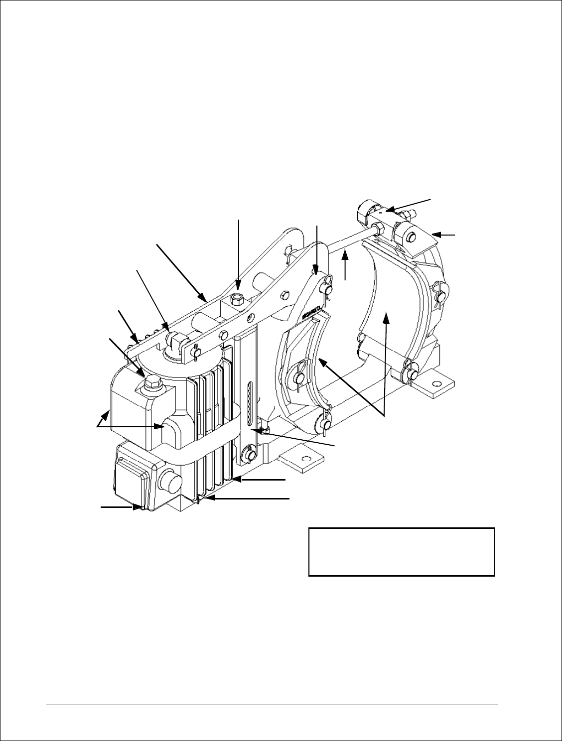
Figure 1 General Arrangement
MST/E Electric Shoe Brake
8/17/2006 Page 8 of 33 MST/E Electric Shoe Brakes Manual
560022-R6
NOTE 1: FILL TO LOWER RIM OF
FILLER HOLE. USE ONLY FLUID
IDENTIFIED ON THE ACTUATOR
NAMEPLATE. DO NOT OVER-FILL
TORQUE ADJUSTMENT
SCR EW (B)
BRAKE LEVER
DRIVE END
PIVOT
MANUAL
RELEASE
FILLER
PLUG
(NOTE 1)
OPTIONAL
TIME
DELAY
VALVES
FIXED
END PIVOT
HY-THRUST ACTUATOR
EXTERNAL TORQUE
SPRING
BRAKE
SHOES
PIVOT
BLOCK
BRAKE
ROD
LINK ARM
(ACTUATOR
END)
TERMINAL WIRING BOX
LINK
ARM
(OUTER
END)
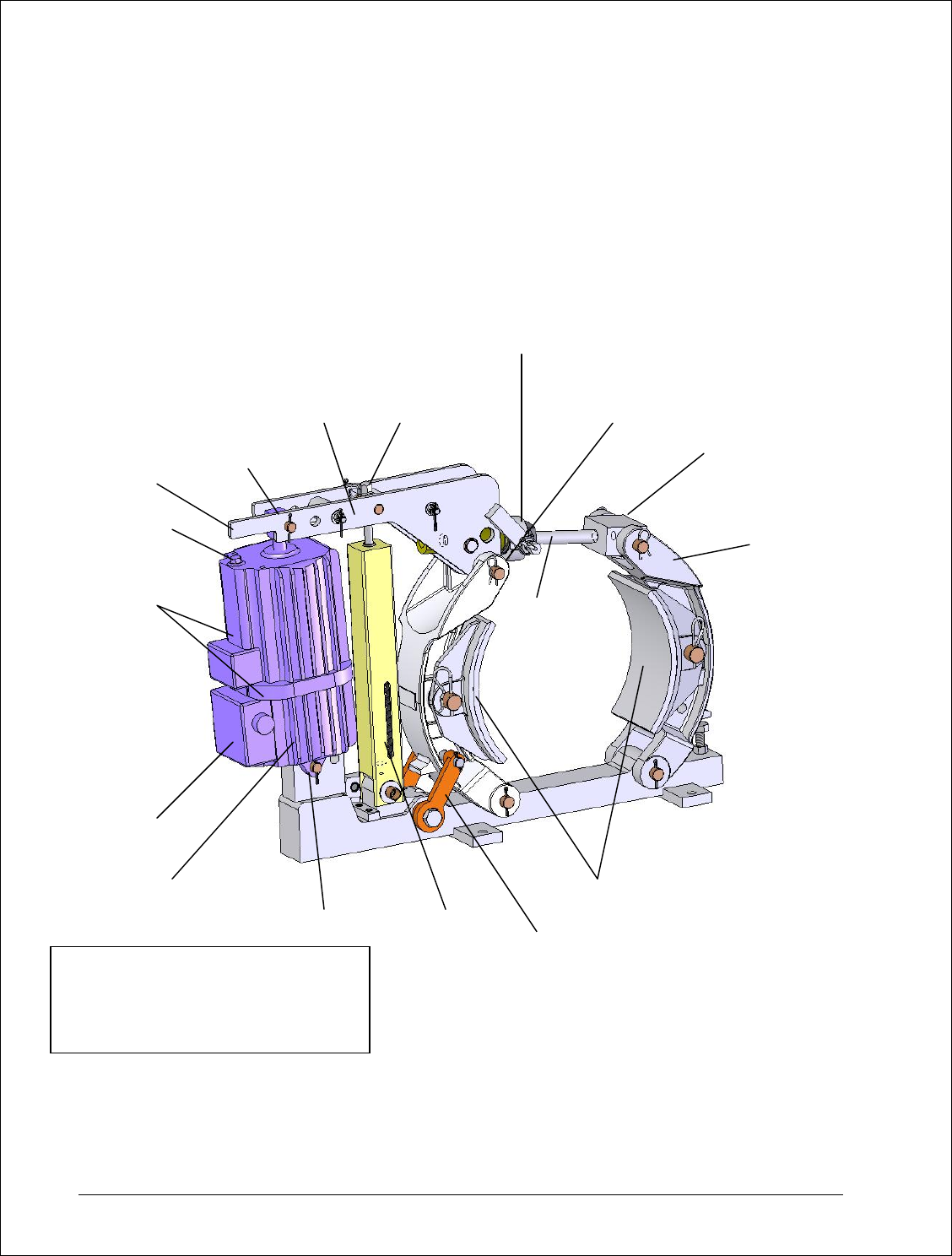
Figure 1a General Arrangement
MST/E Electric Shoe Brake
With Automatic-Adjustment and Automatic-Equalization
A
UTOMATIC
A
DJUSTMENT
(
AA
)
BRAKE LEVER
DRIVE END PIVOT
MANUAL
RELEASE
FILLER PLUG
(
NOTE 1
)
OPTIONAL
TIME DELAYS
TERMINAL
WIRING BO
X
TORQUE
A
DJUSTMENT
SCREW
LINK ARM
(ACTUATOR END)
BRAKE
ROD
PIVOT
BLOCK
LINK ARM
(
OUTER END
)
BRAKE
SHOES
EXTERNAL
TORQUE SPRING
FIXED END
PIVOT
HY-TRUST
A
CTUATOR
A
UTOMATIC
EQUALIZATION
NOTE 1:
FILL TO LOWER RIM OF FILLER HOLE.
USE ONLY FLUID IDENTIFIED ON THE
A
CTUATOR NAMEPLATE. DO NOT
OVERFILL.
8/17/2006 Page 9 of 33 MST/E Electric Shoe Brakes Manual
560022-R6

Chapter 3.0: Application
3.1: The brake covered by this manual is type MST/E. This brake has an adjustable external torque
spring and is generally applied on installations where the required torque cannot be pre-
determined within well defined limits.
3.2: For a given wheel diameter the Association of Iron and Steel Engineers (AISE) determines the
prescribed torque, when applied to 30 and 60 minute rated motors in steel mill applications.
3.3: When applied to four quadrant drives or other applications where wheel heating can be
accurately predicted, type MST/E brakes can be provided with torque values in excess of the
AISE recommendations.
3.4: When the load cycle requires a larger than normal wheel size, as is frequently the case on crane
bridge drive, MST/E brakes can be provided with torques lower than AISE for a given wheel size.
3.5: For applications where larger than normal running clearance is required, a larger actuator can be
applied to a given brake. Typical would be severe applications where wheel expansion can be
considerable or where excessive wheel run-out can be expected.
8/17/2006 Page 10 of 33 MST/E Electric Shoe Brakes Manual
560022-R6

Chapter 4.0: Description of Operation
4.1: The brake is spring applied and actuator released. A heavy-duty compression spring within the
actuator pulls down on the brake lever and forces the shoes against the wheel.
4.2: The actuator piston rod extends when power is applied, the brake-shoe pressure removed and
running shoe clearance established.
4.3: Subject to the effect of brake geometry, braking torque depends upon three major factors:
4.3.(a): The diameter of the wheel.
4.3.(b): The coefficient of friction of the lining material.
4.3.(c): The force with which the linings are applied to the wheel.
4.4: Power applied to the actuator cancels the brakes ability to apply torque.
4.5: The force with which the linings are applied to the wheel depends on the spring length and
characteristics. Spring length increases as linings wear.
4.6: When the brake is released, Automatic Equalization of shoe clearance ensures equal clearance
between each shoe and the wheel.
4.7: Because the applied brake shoe force is proportional to the compressed length of the torque
spring, a slight decrease in brake torque occurs as linings wear (unless automatic adjustment is
used).
4.8: Adjusting the reserve stroke to its specified setting, restores the required spring force.
NEMA states: “The torque ratings apply at a worn lining condition defined as the point where re-
adjustment is required as recommended by the manufacturer”.
4.9: Automatic Equalization (AE) is available on all brakes of this class.
4.10: To understand how the automatic equalization works, it is important to recognize that the total
available shoe clearance is directly related to the length of active stroke and that the actuators
“Fully Released” position is the only consistent value for actuator stroke. The “Brake Applied”
position varies as the linings wear, resulting in a reduced “Reserve Stroke”. The “Brake Applied”
position also varies due to wheel expansion caused by temperature increase; this results in an
increased “Reserve Stroke”.
4.11: On brakes without Automatic Adjustment, after some significant lining wear and the brake wheel
close to ambient temperature, a reduction in the “Reserve Stroke” and a corresponding increase
in the “Active Stroke”, will be noticed. Corrective action will be necessary to ensure the minimum
reserve stroke. (See Chapter 6: “Actuator Stroke Adjustment / Brakes without Automatic
Adjustment).
4.12: On brakes equipped with the Automatic Adjustment (AA) option, the reserve stroke is maintained
by a one-way clutch mechanism arranged to shorten the effective brake rod length – but only
when adjustment is required – as follows:
4.12.(a): A retractable pin mounted on the brake lever, oscillates within a slot in the (AA) clutch
ring. (See Fig. 2A).
8/17/2006 Page 11 of 33 MST/E Electric Shoe Brakes Manual
560022-R6

4.12.(b): When the angle, through which the pin moves within the slot, does not allow contact
with the sides of the slot, nothing happens!
4.12.(c): When the brake applies, after some minimal amount of lining wear, the pin will contact
the side of the slot in the collar, which will advance the ratcheting mechanism and prepare for
adjustment the next time the brake is released.
4.12.(d): When the brake is next released and the load on the thread is minimal, the free wheel
set-up referred to in the previous paragraph will result in an advance on the thread when the pin
engages the other side of the slot in the collar.
4.12.(e): The ratcheting advancement will continue, a little at a time, until the pre-determined
reserve stroke is reached.
4.13: When the brake is released, the shoes are moved apart to provide running clearance from the
wheel. The actuator’s active stroke establishes the total clearance available for both shoes.
4.13.(a): As the brake releases, the shoe nearest to the actuator has been biased to open first.
This is done during manufacture, by inclining the actuator away from the nearest shoe (See Fig.
2).
4.13.(b): Clearance provided to the nearest shoe is restricted by the (AE) mechanism – located
on the base – which transfers the remaining clearance to the other shoe.
4.13.(c): As shoe wear occurs the friction bolt in the (AE) mechanism relocates to provide a new
reference point for the brake shoe on the actuator side of the brake.
4.13.(c).(i): The total available shoe clearance is determined by the active stroke.
4.13.(c).(ii): The clearance between the friction bolt and holes in the actuator links through which
it passes, determines the “actuator side” shoe clearance.
4.14: Various optional features are available, including latching hand release mechanisms, limit
switches, hydraulic and pneumatic overrides, etc. If the brake covered by this manual has any of
the optional features, they will be listed on the front page of this manual and covered by
supplementary instructions.
8/17/2006 Page 12 of 33 MST/E Electric Shoe Brakes Manual
560022-R6
4.15: The actuator for this series of Mondel Brakes can be supplied with optional, factory installed time
delays.
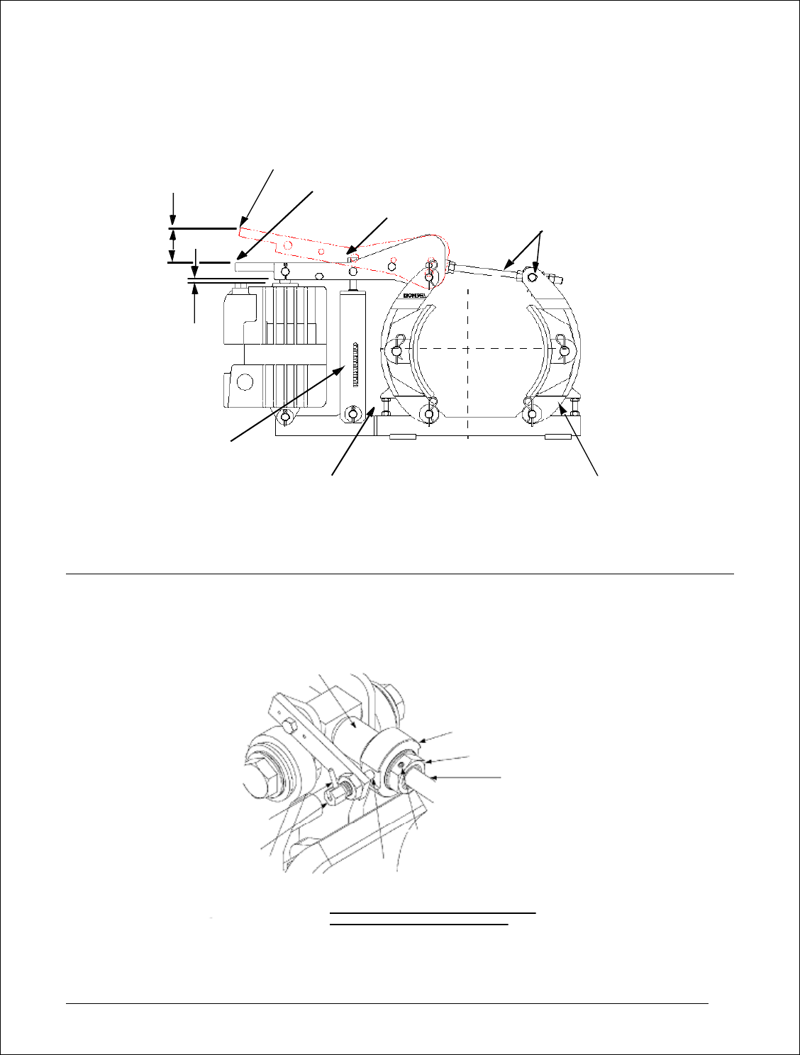
Figure 2 MST/E Brake Shown With Typical Brake Release Lever
Without Automatic Adjustment and Automatic Equalization
Figure 2A MST/E Brake Shown With Typical Brake Release Lever
With Automatic Adjustment and Automatic Equalization
8/17/2006 Page 13 of 33 MST/E Electric Shoe Brakes Manual
560022-R6
CLUTCH DRIVE SHAFT
TANG, PIN (E)
COLLAR (C) PIN (E)
BRAKE ROD
NUT (F)
ROTATOR COLLAR (R)
THIS SET SCREW AND ANOTHER 60 DEGS.
APART, ARE FACTORY SET TO MAINTAIN THE
INTEGRITY OF THE CLUTCH MECHANISM.
DO NOT DISASSEMBLE.
NOTE: TABLE 5 LISTS THE NEMA MINIMUM
RECOMMENDED LINING THICKNESS.
BRAK E LEVE R IN RELEASED POS ITION
BRAKE LEVER IN APPLIED POSITION
ACTIVE
STROKE
RESERVE
STROKE
SHOE CLEARANCE
EQUALIZING BOLT
SHOE CLEARANCE
EQUALIZI NG BOLT
TORQUE ADJUSTMENT SCREW (B)
TORQUE SPRING
SETTING SCALE
TOLERANCE +/- 1/32”
ON ALIGNMENT
BETWEEN BRAKE
HORIZONTAL
AND WHEEL
CENTER LINES
TO LERANCE +/- 1/32” ON ALIGNMENT BETWEEN
BRAKE AND WHEEL VERTICAL CENTER LINES
LOCK-NUTS (F)
(Not available on
MST/E with Au tomat ic Adjustment ) (Shipping Bolt on
MST/E with Automatic
Adjustment)

Chapter 5.0: Installation
5.1: After unpacking, visually inspect the brake assembly to ensure that damage has not occurred
during shipment and that there are no loose or missing parts.
5.2: Prepare the brake support structure and install the brake assembly subject to the following:
5.2.(a): Allow adequate clearance between the brake and adjacent obstructions to allow access
for adjustment and maintenance.
Brake shoe replacement requires space for complete withdrawal of the link arm pivot pins.
5.2.(b): Whether mounting a brake in a new or existing installation, the base mounting bolts need
a reasonable clearance in the base mounting holes to allow the brake to be aligned for full
contact between the brake linings and the wheel.
5.2.(c): Circumstances may determine the best order of installation for the brake and the wheel.
This may be due to the available space or handling facilities on site; generally the wheel is
installed first.
5.2.(d): Center the brake shoes across the width of the brake wheel. This avoids ridge formation
and the possible creation of a dangerous situation as the linings wear.
5.3: Alternatively, it may be necessary to introduce the brake to the brake wheel from one side of the
wheel. In this case partial dismantling of the brake may be required depending on the
circumstances. Refer to the general arrangement and exploded view drawings in this manual to
evaluate the options.
5.3.(a): After installing the brake and wheel, make preliminary adjustments to apply sufficient
shoe pressure to raise the actuator piston rod ½” above its fully retracted position.
5.3.(b): This will apply the brake at approximately rated torque, causing the brake to square itself
to the wheel and maximize the shoe contact area, providing the bolt hole clearance will permit.
5.3.(c): When the brake assembly is correctly aligned and clamped to the wheel, loosen each of
the securing bolts in turn and verify clearance in the base mounting holes. This will ensure
tolerance to allow minor adjustment to the brake alignment to accommodate future relined shoes.
5.3.(d): For the reason identified in the previous paragraph Magnetek does not recommend
“Dowelling” or “Keeper Plates” to maintain alignment.
5.4: Type MST/E brakes are generally installed with the base horizontal and the brake wheel shaft
horizontal.
5.5: In most applications the brake can be installed from one side of the brake wheel. Alternatively it
may be necessary to partially dismantle the brake.
5.6: Type MST/E brakes can also be wall mounted, with the brake wheel shaft horizontal. This is only
possible if the actuator pump suction is flooded, which will be the case if the actuator hydraulic
section filler plug is at the highest point possible with the actuator horizontal. For this mounting
arrangement the actuator is best located above the wheel. The equalizing bolt opposite the
actuator will be most effective in ensuring equal shoe clearance.
8/17/2006 Page 14 of 33 MST/E Electric Shoe Brakes Manual
560022-R6

5.7: Type MST/E brakes can also be wall mounted with the brake wheel shaft vertical. Again this
requires the actuator hydraulic section filler plug to be at the highest point possible with the
actuator horizontal. For this mounting arrangement both equalizing bolts may be required to
ensure equal shoe clearance.
5.8: For any other mounting arrangements consult factory.
5.9: The brake assembly must always be square and aligned to the brake wheel within a maximum of
± 1/32 inch, in three axes (horizontal, vertical, and longitudinal).
5.9.(a): Adjust the brake support bracket to achieve the specified horizontal and longitudinal
alignment. For best performance, the brake base should be flat and parallel to the wheel rim or
motor shaft. It may be necessary to release and re-apply the brake pressure several times to
achieve optimum alignment. Shim under the brake base for the vertical alignment.
5.9.(b): When the brake assembly is correctly aligned and clamped to the wheel, check the
securing bolt clearance in each of the brake base holes. There must be clearance in the base
and through the brake support bracket to allow minor adjustments. Be sure that the brake shoes
are still aligned parallel to the face of the brake and that each brake shoe is fully secured to its
link arm.
5.9.(c): With the brake fully applied, verify that the shoes are centered on the wheel face and that
lining contact is within adequate bedding range.
5.9.(d): When the brake is correctly aligned in all three axes, tighten the brake mounting bolts
and re-check the alignment.
8/17/2006 Page 15 of 33 MST/E Electric Shoe Brakes Manual
560022-R6
5.10: Connect the actuator to the electrical supply using a flexible, sealed conductor, suitable for the
rated temperature. Use type “S0”, or higher temperature, cable. The actuator must be allowed
few degrees of movement without the risk of dirt or moisture entering the terminal box. Chapter 7
provides all necessary electrical details.

Chapter 6.0: Adjustment
6.1: Following any adjustment or repair of the brake, test operation of the brake as described under
“Operational test”, Chapter 8.
6.2: Complete adjustment is required following any rework where any settings were disturbed.
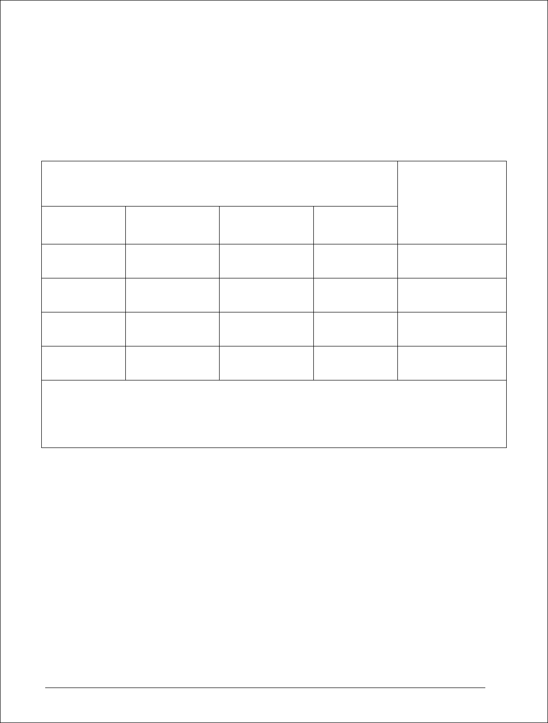
Table 1
BRAKE WHEEL
SIZES (Inches)
TYPICAL RUNNING
CLEARANCE
BETWEEN LINING
AND BRAKE
WHEEL (Inches)
MAXIMUM FULL
SPEED BRAKE
WHEEL run-out
(Inches)
6
8
10
13
16
19
0.014
0.016
0.020
0.026
0.032
0.038
0.006
0.008
0.010
0.013
0.016
0.019
Notes:
1. Refer to “Brake Installation” and “Replacing the Brake Shoes” for adjustment
instructions.
2. Evaluate brake wheel run-out at full speed. It must not exceed value shown in this
table.
6.3: Manual Operation
6.3.(a): Brake installation, shoe replacement, and actuator replacement, described elsewhere,
require the brake to be released and reapplied without energizing the actuator. When type “S”
Latching Hand Release is fitted, it can be used; or it can be manually over-ridden as follows:
6.3.(b): Brakes without Automatic Adjustment:
6.3.(b).(i): To manually release the brake: Adjust the brake rod hex-nuts – to increase the brake
rod length – reducing the “reserve stroke” until the piston rod is no longer visible. Continue
adjustment until there is sufficient lining to brake wheel clearance.
6.3.(c): To manually apply the brake: Adjust the brake rod hex-nuts – to decrease the brake rod
length – increasing the “reserve stroke” until the linings contact the brake wheel. Continue until
the brake release lever begins to rise. Proceed to “Actuator Stroke Adjustment”.
6.3.(d): Brakes with Automatic Adjustment:
6.3.(e): To manually release the brake: Refer to Fig. 2A, withdraw drive pin (E), then carefully
rotate the mechanism by hand to increase the brake rod length and, at the same time, reduce the
reserve stroke until the piston rod is no longer visible. Continue adjustment until there is sufficient
shoe/wheel clearance.
8/17/2006 Page 16 of 33 MST/E Electric Shoe Brakes Manual
560022-R6
6.3.(f): To manually apply the brake: Refer to Fig. 2A and withdraw drive pin (E), then rotate the
mechanism by hand to decrease the effective brake rod length until the linings contact the wheel
and the brake lever begins to rise. Proceed to “Actuator Stroke Adjustment”.
6.4: Actuator Stroke Adjustment
6.4.(a): When power is applied to the actuator the piston will be caused to extend. This will
compress the external spring and raise the brake lever to provide operating clearance between
the shoes and the wheel.
6.4.(b): When power is removed from the actuator, the spring will retract the lever until the shoe
pressure on the wheel prevents any further lever movement as the reserve stroke setting is
attained and the intended brake torque achieved.
6.4.(c): Brakes without Automatic Adjustment:
6.4.(d): Adjust the brake rod nuts until the brake release lever raises the piston rod to the
specified reserve stroke, (Table 2). Re-secure the brake rod nuts against the pivot block.
6.4.(e): Brakes with Automatic Adjustment:
6.4.(f): To make initial adjustment before engaging the auto adjust (AA), refer to Fig. 2A and
withdraw pin (E). Rotate the mechanism by hand to decrease the brake rod length until the
linings contact the wheel and the brake lever begins to rise. Continue adjustment until the
required reserve stroke is about 1/8” less than specified. Re-engage pin (E) allowing the (AA)
mechanism to complete the final stage of the adjustment process. This will verify that the
mechanism is operating correctly.
6.4.(g): Energize the actuator several times until the rotating collar (R) is no longer turned by the
(AA) drive pin (E). Verify that the reserve stroke is still at the desired value per Table 2.
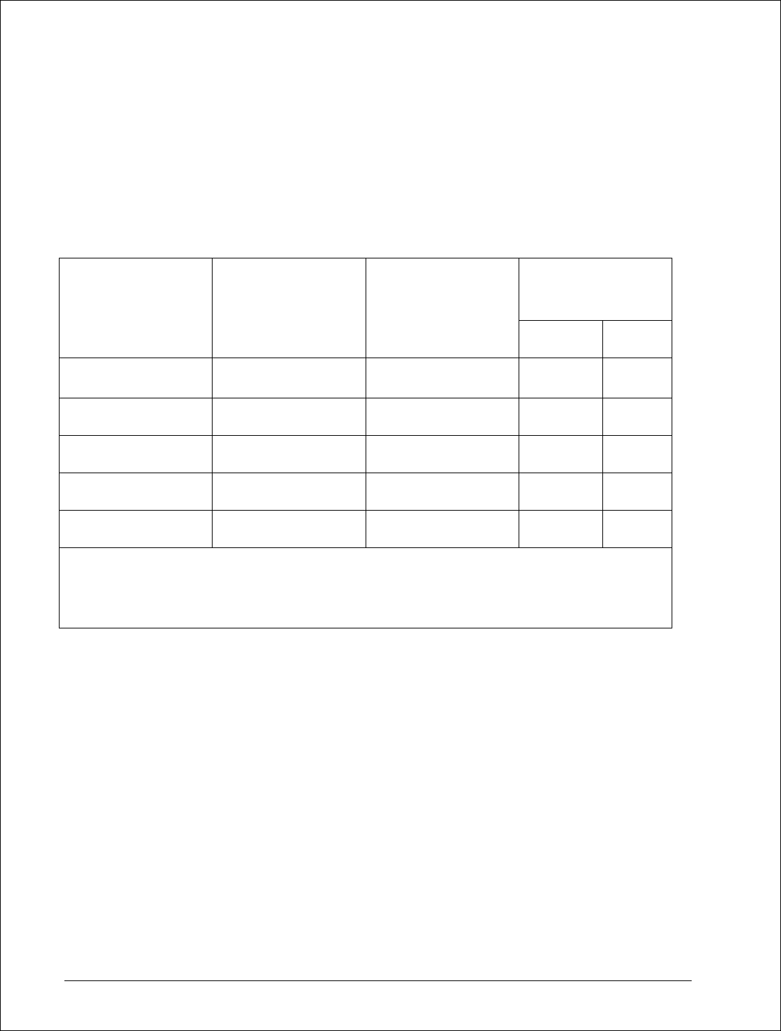
Table 2
ACTUATOR
MAX
STROKE
(inches)
ACTIVE
STROKE
(inches)
DESIRED
RESERVE
STROKE (inches)
Ed23/5
1.97
1.27
0.7
Ed30/5
1.97
1.27
0.7
Ed50/6
2.36
1.56
0.8
Ed80/6
2.36
1.56
0.8
Ed121/6
2.36
1.56
0.8
6.5: Torque Adjustment
6.5.(a): The rated torque, as shown on the nameplate, will be developed when the following
conditions are met:
6.5.(a).(i): The brake is applied and aligned properly.
8/17/2006 Page 17 of 33 MST/E Electric Shoe Brakes Manual
560022-R6
6.5.(a).(ii): The actuator stroke is correct.

6.5.(a).(iii): The correct linings are fitted.
6.5.(a).(iv): The linings are in good condition and bedding is completed.
6.5.(a).(v): The brake wheel is aligned and in good condition.
6.5.(b): Torque adjustment for Mondel MST/E brakes is adjustable on site. Tighten or loosen
screw (B), see Fig. 2, to set the torque within the prescribed range shown on the scale. The
torque setting is obtained by matching the top of the spring-block to a line on the spring scale.
6.6: Automatic Equalization Assembly
6.6.(a): The total available shoe clearance is determined by the active stroke of the actuator.
Distribution of the resulting clearance is determined by two factors.
6.6.(a).(i): As the brake releases under power, the shoe nearest to the actuator has been biased
to open first. This is done during manufacture by inclining the actuator away from the nearest
shoe. (Fig. 2).
6.6.(a).(ii): Clearance provided to the nearest shoe is restricted by the (AE) mechanism located
on the base. The clearance between the friction bolt and holes in the base, through which it
passes, determines the “actuator side” shoe clearance.
6.6.(b): When the predetermined “actuator side” shoe clearance has been established, the
remaining clearance is transferred to the “non-actuator side” shoe.
6.6.(c): As lining wear occurs, the friction bolt in the (AE) mechanism is dragged to a new
location, to provide the reference point for the shoe clearance on the “actuator side” of the brake.
6.6.(d): The (AE) friction bolt mechanism is self-compensating after initial adjustments are
completed as follows:
6.6.(d).(i): Release the brake and, using a soft-faced mallet if necessary, force the actuator side
link away from the wheel. This will set the actuator side (inner) shoe to the maximum available
clearance.
6.6.(e): The actual clearance which will be allowed to the “actuator side” shoe is determined by
the difference in diameter between the friction bolt shank and the holes in the links, through which
it passes.
6.6.(f): The friction bolt assembly is pre-tensioned at the factory. DO NOT FIELD ADJUST. If
the friction bolt assembly is disturbed for any reason it can be retensioned as follows:
8/17/2006 Page 18 of 33 MST/E Electric Shoe Brakes Manual
560022-R6
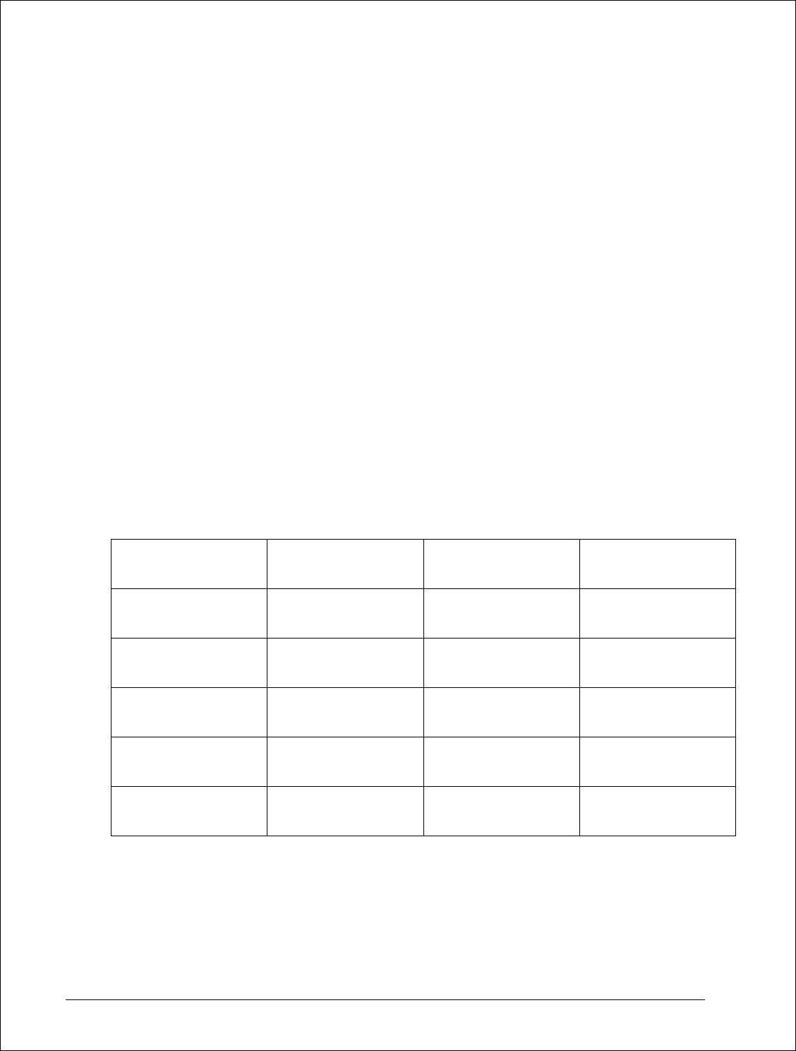
6.6.(g): Refer to Fig. 3a: Install friction bolt through Automatic Equalization arms and base. Add,
onto the end of the friction bolt, a stack of three Belleville washers in series, (as indicated below),
followed by a plain flat washer.
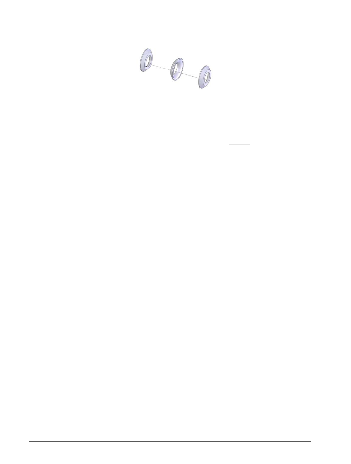
6.6.(g).(i): Install a castle nut, tighten nut until the flat washer is FLUSH with the side of the
Automatic Equalization arm. Loosen or tighten the nut no more than 1/8 of a turn, only enough to
align the nearest cotter pin slot and hole. Install the cotter pin. This completes the assembly.
6.7: Shoe Clearance Adjustment
6.7.(a): The total available shoe clearance is determined by the active stroke of the actuator and
the brake lever ratio. Distribution of the resulting clearance is determined by the setting of the
active shoe clearance equalizing bolt (Fig. 2).
6.7.(b): Generally only one of the two equalizing bolts will be effective depending on the lever
ratio arrangement and subject to the brake being installed horizontally or vertically.
6.7.(c): The “active” equalizing bolt will be evident after energizing the actuator.
6.7.(d): To equalize the brake shoe running clearance:
6.7.(d).(i): Back-off both equalizing bolts and energize the actuator allowing the shoes to move
away from the wheel.
6.7.(d).(ii): Adjust the active side equalizing bolt to limit the travel of that shoe; this moves the
other shoe away from the wheel. Continue adjustment until wheel clearance is equal for both
shoes.
6.7.(d).(iii): Set the non-active side equalizing bolt so that shoe travel is not restricted; lock both
equalizing bolts with jam-nuts.
8/17/2006 Page 19 of 33 MST/E Electric Shoe Brakes Manual
560022-R6
(AE) ARM SIDE
CASTLE NUT SIDE

6.8: Parallel Shoe Gap Adjustment
6.8.(a): For optimum lining wear distribution, brake shoes have controlled freedom to align with
the wheel contour as the linings wear.
6.8.(b): Each brake shoe holder pivots on its link arm. Its freedom to rotate under gravity is
controlled by a shoe holder friction mechanism.
6.8.(c): Spring loaded pins in each link arm bear against the inside of the shoe (Fig. 3). This
provides tension to maintain shoe alignment when the brake is released. The tension is not
adjustable. When a shoe is replaced make sure that both shoe alignment tension mechanisms
are re-installed.
6.8.(d): To align shoes with the wheel, apply the brake at the rated torque and make the
following initial adjustments:
6.8.(d).(i): Release the brake manually or under power.
6.8.(d).(ii): With the brake released, use a soft-faced mallet to tap the upper edge of each brake
shoe, in towards the wheel, in the direction it would rotate under gravity.
6.8.(d).(iii): Re-apply the brake, and the shoes will be forced to align with the wheel to optimize
parallel clearance with the wheel.
6.9: Time Delay Adjustment
6.9.(a): The actuator nameplate will indicate when optional time delay valves are installed.
6.9.(a).(i): Letter “S” indicates an adjustable piston retract, (brake application), time delay.
6.9.(a).(ii): Letter “H” indicates an adjustable piston extend, (brake release), time delay.
6.9.(a).(iii): If both letters “S” and “H” are present, then the actuator is equipped with adjustable
time delay valves independently controlling both the piston extend and retract times.
6.9.(a).(iv): When time delay valves are not fitted, the actuator response time to extend or
retract, is between 0.4 and 0.8 seconds depending on actuator size
6.10: With time delay valve(s) installed, the extend and/or retract times are adjustable between
approximately 0.5 and 10 seconds depending on actuator size.
6.10.(a): Remove the delay valve protective cap to expose the adjustment screw. For minimum
delay set the screw head flush with the housing. Fig. 1 shows valve location.
6.10.(a).(i): Turn the screw clockwise to increase, and counter clockwise to decrease the delay.
Note: The standard actuator has the shortest response time. An actuator fitted with delay(s)
provides longer response times, even when the delay(s) are adjusted for minimum effect.
8/17/2006 Page 20 of 33 MST/E Electric Shoe Brakes Manual
560022-R6
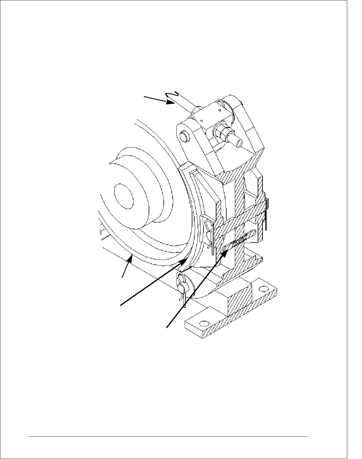
Figure 3 Section Through Shoe And Link Arm
Drawn To Reveal Tension Device
WMF FILE WIP 010212
8/17/2006 Page 21 of 33 MST/E Electric Shoe Brakes Manual
560022-R6
Figure 3
BRAKE ROD
BRAKE
WHEEL
BRAKE
SHOE
SHOE ALIGNMENT
TENSION DEVICE
SECTION THROUGH SHOE AND LINK ARM
DRAWN TO REVEAL TENSION DEVICE
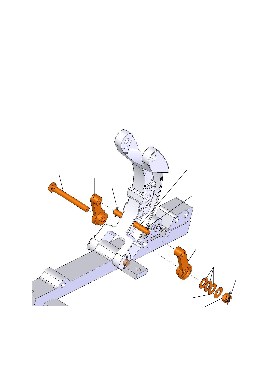
Figure 3A Type AE Automatic Equalization Mechanism Assembly
560022-R6
FRICTION BOLT
CASTLE NUT
FLAT WASHER
A
UTO EQUALIZE
A
RM
A
UTO EQUALIZE
A
RM
BELLVILLE
WASHER (3)
COTTER PIN
COTTER PIN
(AE) IDLER PIVOT PIN
COTTER PIN
8/17/2006 Page 22 of 33 MST/E Electric Shoe Brakes Manual
Chapter 7.0: Electrical Detail
7.1: Operation of the actuator is not dependant of the direction of motor rotation. The cable leads can
be connected to the U1, V1 and W1, (T1, T2, T3), terminals in any phase sequence.
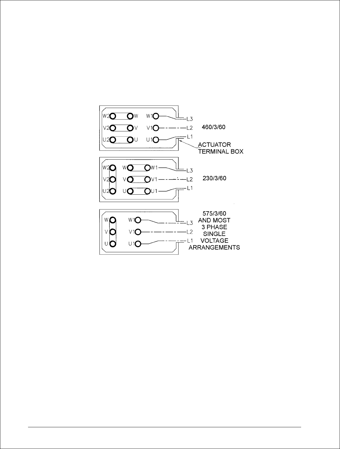
Figure 4 Electrical Connections
7.2: The motor leaves the factory already arranged for the specified voltage, which is also shown on
the nameplate.
7.3: If the motor was specified for a nominal 460 volts supply, it will be connected with nine terminals
and the links arranged as shown in Fig. 4. If at some future date the motor is required to operate
from a 230 volts supply, re-arrangement of the links is required as shown.
7.4: When specified for operation on 575 Volts or other single voltage, it will be connected with six
terminals, the links arranged as shown in Fig. 4. The winding will not be capable of re-connection
for any other voltage.
7.5: Explosion Proof actuators are only arranged for the terminal voltage shown on the nameplate.
Three terminal posts will be visible when the cover plate is removed under the required
conditions. No provision is made for external re-connection to any other voltage.
8/17/2006 Page 23 of 33 MST/E Electric Shoe Brakes Manual
560022-R6
7.6: A wiring diagram showing the possible terminal link arrangements is fastened inside the actuator
terminal box cover.

Chapter 8.0: Operational Test
8.1: Heed all warnings and cautions in addition to the owners’ safety procedures.
8.2: Follow all standards and local statutes.
8.3: Remove any drum chocks on a hoist application.
8.4: As a preliminary test of the brake without load, energize the actuator for one short jog. If the
brake fails to stop and hold the motion stationary, repair or re-adjust the brake as necessary.
Visually inspect the brake during operation to ensure all adjustments are correct. If successful,
continue with longer duration jogs until confident that the brake is operating satisfactorily.
8.5: A minimum of 60% contact between lining and wheel on each shoe is required before subjecting
the brake to its rated capacity.
8.6: If re-lined shoes have been fitted, or the brake alignment has been altered or is otherwise
suspect, you may have to realign the brake. This will minimize the bedding needed to obtain the
necessary 60% of brake lining to wheel contact.
8.7: The required lining contact is seldom achieved without “bedding”, but time spent to achieve
satisfactory bedding will be rewarded with a considerably longer life for the lining.
8.8: Modern linings, although hard wearing, are difficult to “bed” when the area in contact with the
wheel cannot support the heat energy transferred to the brake. As a result the linings will
become “glazed” where in contact with the wheel. “Glazing” is the name applied to a condition
where the lining has been heated beyond its working temperature range and is no longer capable
of its designed coefficient of friction. “Glazing” will seldom be removed by further braking
operations as any increase in area of lining contact will immediately be glazed.
8.9: “Glazing” can be prevented by ensuring a minimum of 60% contact area before placing the brake
in service.
8.10: On hoists, well spaced, short bursts of energy, such as an E.Stop at high speed with no load are
best to achieve initial “bedding”. This will limit the energy input while the wheel is monitored for
temperature.
8.11: A distinct advantage of the type MST/E brakes is that the actuator can be easily overridden while
the drive is operating. This can be accomplished with a short length of pipe fitted over the
“manual release lever extension”, Fig. 1. When circumstances permit, pressure can be applied to
force the shoes against the wheel while the drive is operating. Care must be taken to achieve the
minimum 60% contact between lining and wheel on each shoe, without exceeding the maximum
of 150°C.
8.12: Bedding is just as important when the brake is applied with a four quadrant drive, and not
subjected to dynamic loading, except under emergency conditions.
8.13: The following are the key steps to satisfactory “bedding” to extend lining life.
8.13.(a): Use only genuine Mondel lined brake shoes. This will maintain specified brake
performance and ensure that the braking torque is neither more nor less than the specified rating.
8.13.(a).(i): Linings thicker than the original equipment may result in contact with the wheel only
at the tips.
8/17/2006 Page 24 of 33 MST/E Electric Shoe Brakes Manual
560022-R6

8.13.(a).(ii): Linings thinner than the original equipment may result in contact with the wheel only
across the middle and cause vibration during stops.
8.13.(b): Do no use re-lined shoes where the castings are damaged, worn or distorted.
8.13.(c): Square the brake to the wheel for optimum contact between the linings and the wheel.
8.13.(d): Type MST/E brakes utilize shoe clearance equalizing bolts to equalize brake shoe
clearance; ensure that they are correctly adjusted in accordance with Chapter 6.
8.13.(e): Type MST/E brakes incorporate a mechanism to keep brake shoe clearance parallel to
the wheel; ensure that it is correctly adjusted in accordance with Chapter 6.
8.14: Wheel run-out must be within the allowable tolerance; see Table 1. Any unnecessary lining drag
will result in excessive heat in the wheel and lining deterioration.
8.15: Every operational test should include verification of brake wheel run-out as follows:
8.15.(a): At all speeds, verify that the linings are clear of the wheel. Take steps to correct wheel
run-out, imbalance or the effects of critical speed.
8.15.(b): If necessary, check low speed brake wheel run-out as follows:
8/17/2006 Page 25 of 33 MST/E Electric Shoe Brakes Manual
560022-R6
8.15.(c): Using a run-out gauge, verify that radial run-out does not exceed 0.001” per inch of
brake wheel diameter. Refer to Table 1 for brake wheel run-out allowance. Bearing play can
also be checked by lifting the brake wheel with a suitable lever while observing the dial gauge.

Chapter 9.0: Maintenance and Repair
NEMA Standard ICS 9-1993, Part 1 recommends that brakes be fitted with new or re-lined shoes
before the lining material is worn excessively. Refer to Table 4 for minimum thickness.
9.1: Replacing the Brake Shoes
9.1.(a): Remove and reinstall the brake shoes as follows. Use a lifting devise as necessary.
9.1.(a).(i): On a hoist lower the load to the floor and disconnect the load from the bottom block.
9.1.(a).(ii): Reset the bottom block on the floor, or on a suitable support. Chock drum to prevent
rotation of the drum.
9.1.(a).(iii): Refer to Fig. 5.
9.1.(a).(iv): (1) Manually release the brake as instructed in Chapter 6.
9.1.(a).(v): (2) Remove cotter pin and withdraw the actuator drive end pivot pin.
9.1.(a).(vi): (3) Remove hitch pin at the active upper end of each link arm; withdraw the pivot
pins.
9.1.(a).(vii): (4) Lift the brake rod and lever assembly clear of the brake body.
9.1.(a).(viii): (5) Remove hitch pin at the fixed lower end of each link arm; withdraw the pivot
pins.
9.1.(a).(ix): (6) Lift out the link arm/brake shoe assemblies.
9.1.(a).(x): (7) Remove hitch pins and withdraw the shoe pivot pins.
9.1.(a).(xi): (8) Brake shoes can now be removed for service. To avoid loss, restrain the spring
loaded shoe alignment tension device when removing a shoe.
8/17/2006 Page 26 of 33 MST/E Electric Shoe Brakes Manual
560022-R6
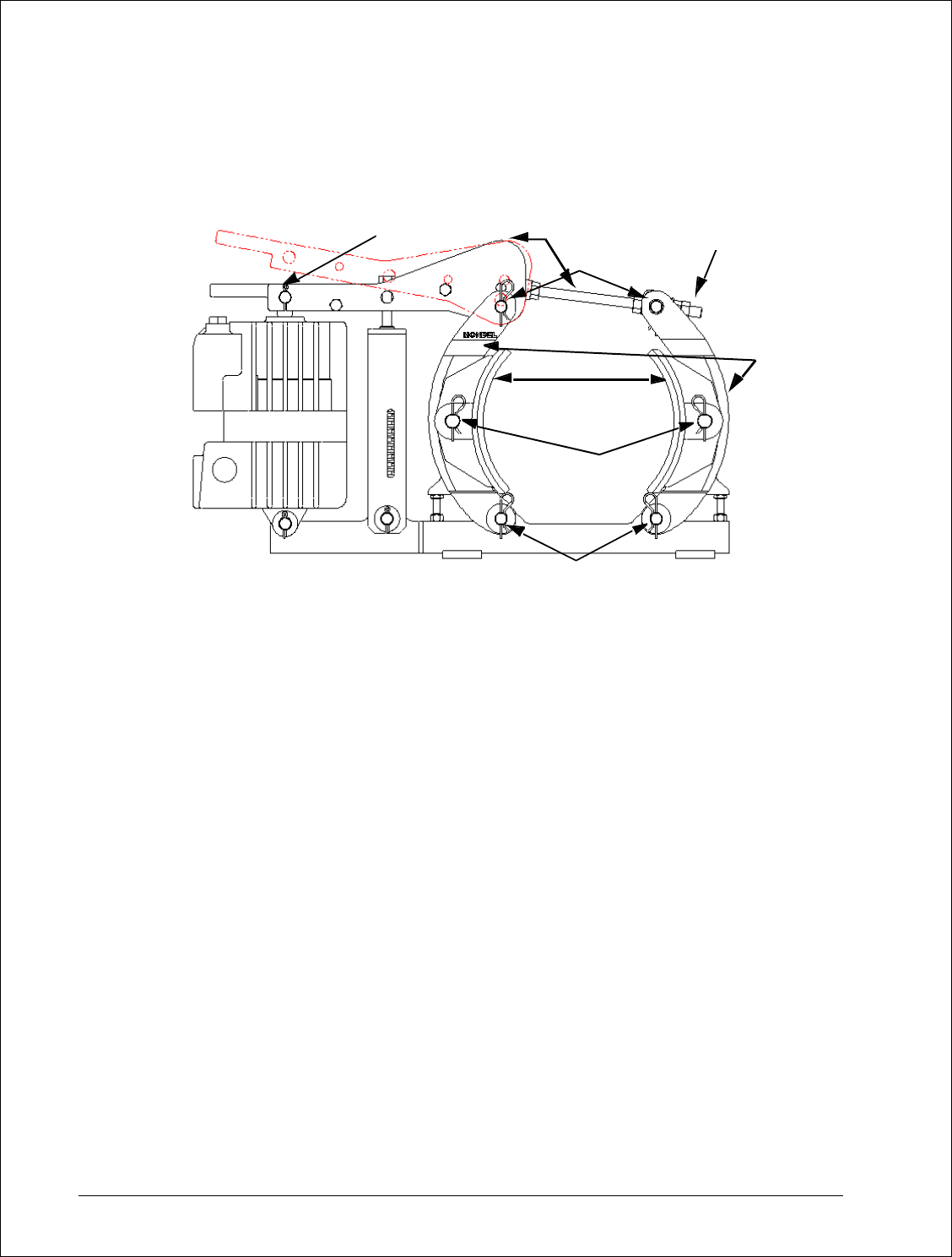
Figure 5 Brake Shoe Removal
9.1.(a).(xii): Before starting shoe installation, check that the brake surface of the wheel is clean
and free from oil and grease.
9.1.(a).(xiii): Next, verify that the lining surface will be true to the wheel when the shoe is
installed. Carefully check lining contact with the wheel. Remove any high spots with emery
paper to ensure 60% contact between the lining and the wheel.
9.1.(b): Ensure adequate clearance will be available and install the replacement shoe
assemblies in the reverse order.
9.1.(c): Replace all pivot, cotter and hitch pins.
9.1.(d): Re-apply the brake and make all adjustments covered in Chapter 6.
NOTE: The brake can be damaged if the brake shoes are not accurately aligned. Do not
operate the brake unless the brake shoes are in their normal position and all pivot, cotter
and hitch pins are fully installed.
9.1.(e): Newly lined shoes seldom fit perfectly with the contour of an existing brake wheel,
particularly if the wheel is worn or undersized. If the brake has been moved, realignment of the
brake with the wheel may be necessary. Refer to the topic “Brake Installation” for the correct
alignment and bedding procedure.
9.1.(f): Refer to Chapter 6 and adjust the reserve stroke as required.
9.1.(g): Refer to Chapter 6 and adjust the torque as required.
8/17/2006 Page 27 of 33 MST/E Electric Shoe Brakes Manual
560022-R6
(1)
(3)
(4)
(5)
(6)
(8)
(7)
(2)
9.1.(h): Refer to Chapter 6 and adjust the brake shoe clearance as required.
9.1.(i): Refer to Chapter 8; bed and test the brake as described.
9.2: Removing The Actuator
9.2.(a): Secure against any possibility of an unexpected movement when the actuator is
removed.
9.2.(b): Lower the load to the floor and disconnect the load from the bottom block.
9.2.(c): Reset the bottom block on the floor, or on a suitable support. Chock the drum to prevent
rotation.
9.2.(d): Disconnect and remove electrical wiring and conduit to the actuator.
9.2.(e): Before attempting to remove the actuator, release the brake. See Chapter 6: “Manually
Releasing the Brake”.
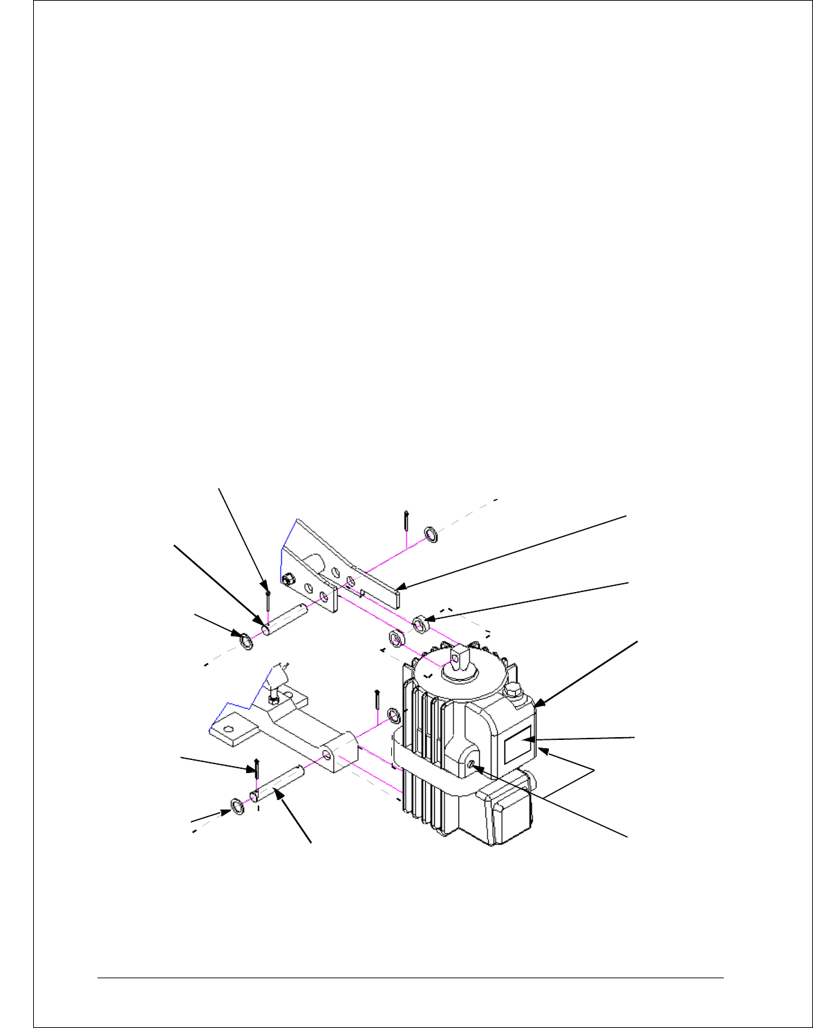
Figure 6 Actuator Removal and/or Replacement
8/17/2006 Page 28 of 33 MST/E Electric Shoe Brakes Manual
560022-R6
Figure 6:
ACTUATOR
SPACERS
MANUAL
RELEASE
LEVER
COTTER PINS
PIVOT PIN,
PLAIN
WASHERS
COTTER
PINS
PLAIN
WASH ER S
PIVOT PIN,
FIXED END
Actuator Removal and/or Replacement
DRIVE END
OPTIONAL TIME
DELAY VALVE(S)
DATA PLATE
HY-THRUST
ACT UAT OR

9.2.(f): Secure or support the actuator before attempting to remove the pivot pins.
9.2.(g): Refer to Fig. 6: remove the cotter pins and withdraw the pivot pins attaching the actuator
to the brake body.
9.2.(h): Remove the complete actuator using appropriate lifting devices.
9.2.(i): Should service be required, return the actuator to Magnetek for repairs.
9.3: Re-Installing The Actuator
9.3.(a): Verify adequate means are still in place to protect unexpected movement when the
actuator is replaced.
9.3.(b): Position the actuator within the lever and attach to the base. Use a lifting device as
necessary.
9.3.(c): Attach and secure the actuator using the correct pivot pins, etc. Check for wear prior to
re-fitting, Fig. 6.
9.3.(d): Refer to Chapter 6 and adjust the reserve stroke as required.
9.3.(e): Refer to Chapter 6 and adjust the torque as required.
9.3.(f): Refer to Chapter 6 and adjust the brake shoe clearance as required.
9.3.(g): Re-connect the actuator wiring, as required, and replace the terminal box cover.
9.3.(h): Refer to Chapter 8; bed and test the brake as described.
9.4: Re-lining The Brake Shoes
We do not recommend that shoes be re-lined in the field. New bonded shoe assemblies
can be ordered as repair parts. Factory rebuilt shoes are also available from Magnetek.
Under this program, credit will be allowed for old shoes in usable condition.
9.5: Removal and Installation of Motor and Brake Wheel as an Assembly
9.5.(a): Quick replacement of the drive motor and brake wheel, as an assembly, can be
accomplished with minimum disturbance to the brake.
9.5.(b): Disconnect, lock out, and tag out the disconnect switch that feeds this equipment to
prevent power from being applied while service is being performed.
9.5.(c): Remove both shoe assemblies as described under the topic, “Replacing the Brake
Shoes”. If the shoes will not be replaced as part of this work order, identify the shoes in order
that they can be re-fitted without having to be re-bedded.
9.5.(d): Swing the entire brake rod assembly clear to permit unobstructed vertical withdrawal of
the brake wheel without damage.
9.5.(e): Remove the motor and brake wheel by lifting straight up until the wheel clears the brake.
9.5.(f): Install the motor and brake wheel by lowering it into place.
8/17/2006 Page 29 of 33 MST/E Electric Shoe Brakes Manual
560022-R6

9.5.(g): Re-install the shoe assemblies as described under the topic “Replacing the Brake
Shoes”.
9.5.(h): Re-attach the brake rod to the brake lever.
9.5.(i): Ensure that all shoe holder pivot and hitch pins are correctly installed.
9.5.(j): Test the operation of the brake as described under the topic “Operational Test”.
9.5.(k): Install the brake wheel as described elsewhere.
9.5.(l): Verify the brake is still properly centered over the wheel. Make any adjustments as
required. See Chapter 5, “Brake Installation”.
9.5.(m): Maintenance and inspection periods depend on operating conditions. High duty cycle
applications obviously require more frequent inspections than brakes operating on low duty cycle
applications. In either case, we recommend a general inspection every 100 operating hours or
every month minimum.
9.6: Inspection
9.6.(a): Electrical connections and mechanical fasteners should be checked for tightness.
Inspect the brake wheel to ensure that it is neither damaged nor loose. Inspect the brake
mounting bolts for tightness, and that brake shoe clearance settings are within specifications.
9.6.(b): Inspect the brake wheel for unusual scoring, signs of over-heating, cracking or wear.
Replace any damaged, cracked or excessively worn brake wheels.
9.6.(c): Inspect the condition of the bearings and bushings as well as the electrical and
mechanical integrity of the complete braking system. Make any repairs or adjustments that may
be required to ensure proper brake system operation.
9.6.(d): Check the brake wheel run-out at all speeds. See Chapter 8, “Operational Test”.
9.6.(e): Correct operation of the motor can be determined by measuring its operating current.
Refer to motor nameplate for rated value.
9.7: Lubrication
9.7.(a): Periodic lubrication is not required on these brakes. Oil or any other lubricant applied to
any part of the brake may trap airborne contaminants.
9.8: Actuator Working Fluid
9.8.(a): The actuator leaves the factory correctly filled with the fluid and seals for the specified
operating temperature range.
9.8.(b): The fluid will not deteriorate in service, and if there are no tell-tale signs of leakage, no
additional fluid will be required.
9.8.(c): The actuator working fluid should be checked periodically, but must not be overfilled to
ensure an adequate air space is retained to allow for fluid expansion. See Fig. 1 for plug location
and proper fluid level.
8/17/2006 Page 30 of 33 MST/E Electric Shoe Brakes Manual
560022-R6
9.8.(d): If additional fluid is necessary for any reason, use only the fluid identified on the
nameplate to ensure compatibility with the installed seals and the specified operating temperature
range. DO NOT OVER-FILL.
9.8.(e): Table 3 specifies Recommended Hydraulic Fluid types for a range of ambient
temperatures.
Table 3: Recommended Hydraulic Fluids
Ambient Temperature
Hydraulic
Fluid
Lower Limit
0F
Upper Limit
0F
Lower Limit
0C
Upper Limit
0C
-13
+122
-25
+50
C-10 (1)
+32
+176
0
+80
C-46 (1)
-31
+104
-35
+40
Aero 41 (2)
-76
+140
-60
+60
M-20 (3)
(1) C-10 and C-46 are Shell Tellus® products.
(2) Aero 41 is a Shell® product.
(3) M-20 is a Bayer® Baysilone product.
All hydraulic fluids are obtainable from Magnetek.
9.9: Brake Adjustments
9.9.(a): Wear will be more rapid when the linings are new, while the high spots are wearing down
as the bedding process takes place. Adjustment will be required soon after the brake has been
put into service.
9.9.(b): Brake release lever travel increases with lining wear. This decreases the reserve stroke.
Carry out periodic maintenance to reset the reserve stroke as described in Chapter 6 “Actuator
Stroke Adjustment”.
9.9.(c): Brake torque decreases as the brake lever drops. On critical applications, such as
hoists, brake adjustment should be performed frequently enough so that the torque loss does not
result in loss of load control. In no event should the lever be allowed to “bottom out”. This results
in total loss of braking torque and could result in death or injury to personnel.
8/17/2006 Page 31 of 33 MST/E Electric Shoe Brakes Manual
560022-R6
Following any adjustment, maintenance or repair on the brake, fully test its operation as
described under topic “Operational Test”.
Chapter 10.0: Replacement Parts
10.1: Brake Lining Replacement
10.1.(a): As a general guide, Magnetek recommends that brake linings be replaced when the
linings wear down to 1/16” minimum thickness. Table 4, taken from standard ICS 9-1993, Part 1:
Electromagnetic Brakes, shows NEMA’s recommended range of minimum lining thickness for
bonded and riveted linings on brake wheels from 8” to 19” diameter…
Table 4
Lining Thickness
(Inches) (2)
Wheel
Diameter
(Inches)
Maximum
RPM
Ductile
Iron
Minimum
Wheel Dia.
(Inches)
(1)
Riveted (3)
Bonded
8
5000
7.94
0.010
0.016
10
4000
9.92
0.010
0.020
13
3300
12.90
0.010
0.026
16
2600
15.87
0.015
0.032
19
2300
18.87
0.015
0.038
(1) Minimum after re-machining.
(2) Minimum permissible prior to replacement.
(3) Above rivet head at maximum wear point.
10.2: Detailed procedures for brake shoe replacement and actuator removal and installation are
covered earlier in this manual.
10.3: For other parts replacement or complete disassembly and rebuild, refer to the exploded view
attached to this manual.
10.4: Before returning a brake to service after major repairs or overhaul, carry out all adjustments
outlined in this manual followed by a complete operational test.
10.5: Ordering Parts
10.5.(a): For part number and identification refer to the Exploded View and Bill of Material
forming part of this manual.
10.5.(b): Always quote the Magnetek Serial Number when ordering parts.
8/17/2006 Page 32 of 33 MST/E Electric Shoe Brakes Manual
560022-R6
10.5.(c): For optimum brake life and performance use only genuine Mondel parts.

Chapter 11.0: Long Term Storage
11.1: If a brake assembly will not be installed immediately, it can be stored indoors in a dry location
indefinitely or outdoors for a reasonable time if adequately protected from moisture and corrosive
atmosphere. The brake assembly must always be protected from direct exposure to the
elements unless specifically treated at the factory for use in that environment. Covering with
plastic sheeting is not acceptable unless provision is made to prevent condensation under the
plastic.
11.2: During storage, rust may form on the surface of the brake wheel. This is not usually a problem
with ductile iron wheels nor is it necessary to clean the wheel before placing the wheel in service.
The first few brake applications will polish the wheel.
11.3: Steel wheels may form scale when corroded, and the braking surface may have to be re-
machined to remove the scale. See Table 4 for machining limits. Dynamic balance may be
affected.
11.4: Before painting a brake, protect all pivot points, pull-rod, actuator piston, brake wheel and linings,
etc.
11.4.(a): Data plates and labels must not be removed or painted over.
8/17/2006 Page 33 of 33 MST/E Electric Shoe Brakes Manual
560022-R6
