Magnetrol R86 Pulsar radar R86 26 GHz User Manual Layout 1
Magnetrol Pulsar radar R86 26 GHz Layout 1
Contents
- 1. User Manual
- 2. User Manual Revised
User Manual Revised

2014/68/EU
High Performance 26 GHz
Pulse Burst Radar
Level Transmitter
Installation and Operating
Manual for Pulsar®Model R86
with HART®output
Software Version 1.x
11:41 am, Apr 13, 2017

58-603 Pulsar® Model R86 Radar Transmitter
Read this Manual Before Installing
This manual provides information on the Pulsar®Model
R86 Radar transmitter. It is important that all instruc-
tions are read carefully and followed in sequence. The
QuickStart Installation instructions are a brief guide to the
sequence of steps for experienced technicians to follow
when installing the equipment. Detailed instructions are
included in the Complete Installation section of this manual.
Conventions Used in this Manual
Certain conventions are used in this manual to convey
specific types of information. General technical material,
support data, and safety information are presented in nar-
rative form. The following styles are used for notes, cau-
tions, and warnings.
NOTES
Notes contain information that augments or clarifies
an operating step. Notes do not normally contain
actions. They follow the procedural steps to which
they refer.
Cautions
Cautions alert the technician to special conditions that
could injure personnel, damage equipment, or reduce
a component’s mechanical integrity. Cautions are also
used to alert the technician to unsafe practices or the
need for special protective equipment or specific mate-
rials. In this manual, a caution box indicates a poten-
tially hazardous situation which, if not avoided, may
result in minor or moderate injury.
WARNINGS
Warnings identify potentially dangerous situations or
serious hazards. In this manual, a warning indicates an
imminently hazardous situation which, if not avoided,
could result in serious injury or death.
Safety Messages
The PULSAR Model R86 system is designed for use in
Category II, Pollution Degree 2 installations. Follow all
standard industry procedures for servicing electrical and
computer equipment when working with or around high
voltage. Always shut off the power supply before touching
any components. Although high voltage is not present in
this system, it may be present in other systems.
Electrical components are sensitive to electrostatic dis-
charge. To prevent equipment damage, observe safety
procedures when working with electrostatic sensitive
components.
This device complies with Part 15 of the FCC rules.
Operation is subject to the following two conditions:
(1) This device may not cause harmful interference, and
(2) This device must accept any interference received,
including interference that may cause undesired operation.
FCC ID: LPN-R86
Any unauthorized changes or modifications not expressly
approved by the party responsible for compliance could
void user’s authority to operate this equipment.
WARNING! Explosion hazard. Do not connect or dis-
connect designs rated Explosion-proof or Non-incendive
unless power has been switched off and/or the area is
known to be non-hazardous.
Low Voltage Directive
For use in Installations Category II, Pollution Degree 2.
If equipment is used in a manner not specified by the
manufacturer, protection provided by equipment may be
impaired.
Notice of Copyright and Limitations
Magnetrol®& Magnetrol®logotype and Pulsar®
are registered trademarks of Magnetrol®International,
Incorporated.
Copyright © 2017 Magnetrol®International,
Incorporated. All rights reserved.
MAGNETROL reserves the right to make changes to the
product described in this manual at any time without
notice. MAGNETROL makes no warranty with respect
to the accuracy of the information in this manual.
Warranty
All MAGNETROL electronic level and flow controls are
warranted free of defects in materials or workmanship for
eighteen months from the date of original factory ship-
ment.
If returned within the warranty period; and, upon facto-
ry inspection of the control, the cause of the claim is
determined to be covered under the warranty; then,
MAGNETROL will repair or replace the control at no cost
to the purchaser (or owner) other than transportation.
MAGNETROL shall not be liable for misapplication,
labor claims, direct or consequential damage or expense
arising from the installation or use of equipment. There
are no other warranties expressed or implied, except spe-
cial written warranties covering some MAGNETROL
products.
Quality Assurance
The quality assurance system in place at MAGNETROL
guarantees the highest level of quality throughout the
company. MAGNETROL is committed to providing
full customer satisfaction both in quality products and
quality service.
The MAGNETROL quality assurance
system is registered to ISO 9001 affirming
its commitment to known international
quality standards providing the strongest
assurance of product/service quality
available.

58-603 Pulsar® Model R86 Radar Transmitter
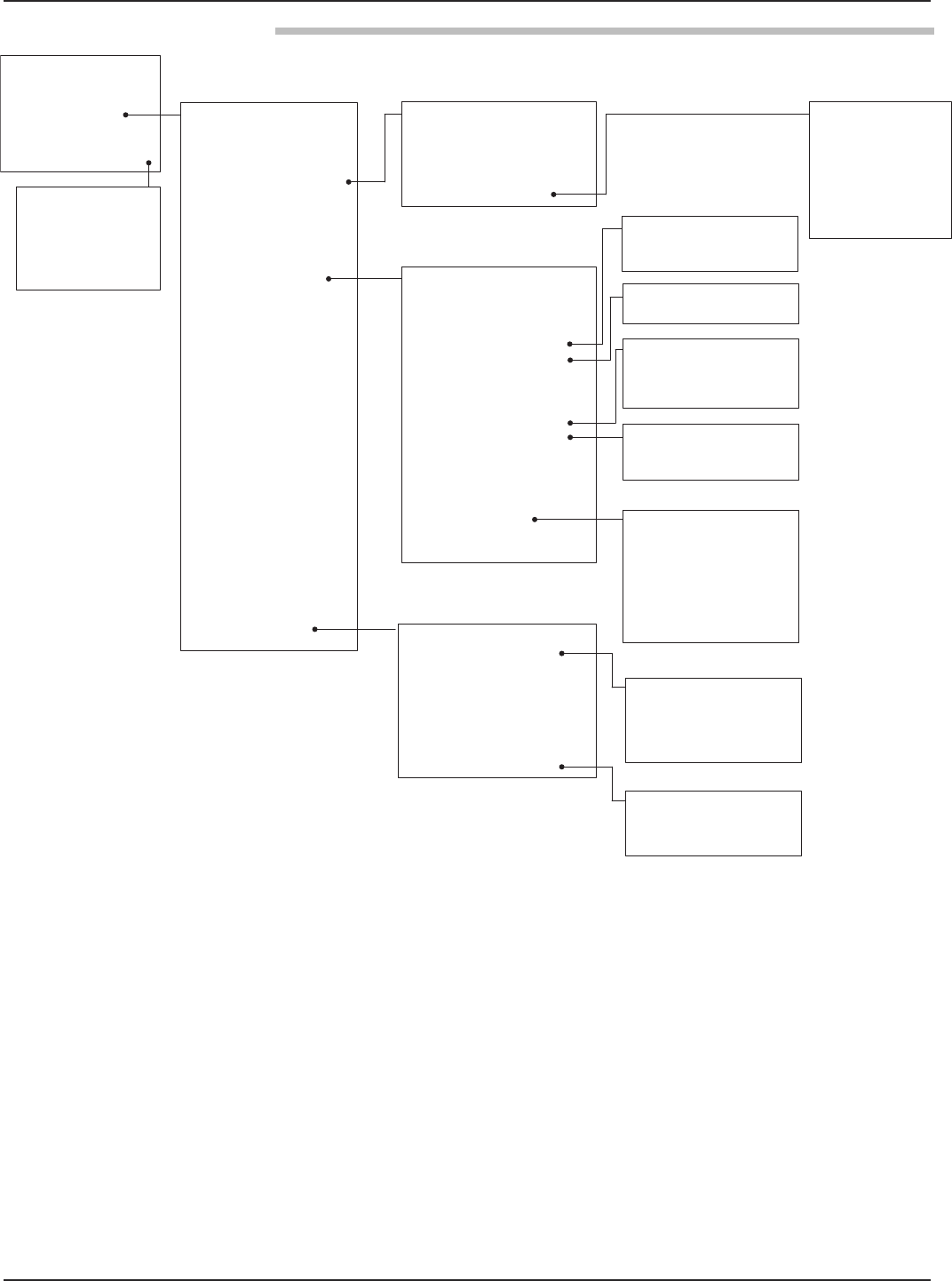
Table of Contents
1.0 QuickStart Installation
1.1 Getting Started..........................................................5
1.1.1 Equipment and Tools..................................... 5
1.1.2 Configuration Information.............................6
1.2 QuickStart Mounting................................................7
1.2.1 Antenna......................................................... 7
1.2.2 Transmitter.....................................................7
1.3 QuickStart Wiring.................................................... 8
1.4 Serup Wizard – Configuration..................................8
1.4.1 Setup Wizard Menu Options....................... 10
1.4.1.1 Setup Wizard Numerical Data Entry.......11
2.0 Complete Installation
2.1 Unpacking.............................................................. 12
2.2 Electronic Discharge (ESD) Handling Procedure....12
2.3 Before You Begin.....................................................13
2.3.1 Site Preparation............................................ 13
2.3.2 Equipment and Tools................................... 13
2.3.3 Operational Considerations..........................13
2.3.3.1 Maximum Distance...............................14
2.3.3.2 Minimum Distance...............................14
2.3.3.3 Problematic Applications;
GWR Alternative.................................. 14
2.4 Mounting................................................................15
2.4.1 Installing the Antenna.................................. 15
2.4.1.1 Location................................................15
2.4.1.2 Beam Angle...........................................15
2.4.1.3 Obstructions......................................... 16
2.4.1.4 Nozzles..................................................16
2.4.1.5 Standpipes and Stillwells....................... 16
2.4.2 Installing the Transmitter............................. 16
2.4.2.1 Low Echo Margin................................. 17
2.5 Wiring.................................................................... 18
2.5.1 General Purpose or Non-Incendive.............. 18
2.5.2 Intrinsically Safe...........................................19
2.5.3 Explosion Proof............................................19
2.6 Configuring the Transmitter....................................20
2.6.1 Bench Configuration....................................20
2.6.2 Menu Traversal and Data Entry....................21
2.6.2.1 Navigating the Menu............................ 21
2.6.2.2 Data Selection.......................................21
2.6.2.3 Entering Numeric Data Using
Digit Entry........................................... 22
2.6.2.4 Entering Numeric Data Using
Increment/Decrement........................... 22
2.6.2.5 Entering Character Data....................... 23
2.6.3 Password Protection..................................... 23
2.6.4 Menu: Step-By-Step Procedure.....................24
2.6.5 Configuration Menu: Device Setup..............27
2.7 Configuration Using HART®..................................32
2.7.1 Connections................................................. 32
2.7.2 Display Menu...............................................32
2.7.3 HART Revision Table.................................. 32
2.7.3.1 Model R86............................................32
2.7.4 HART Menu................................................33
3.0 Reference Information
3.1 Description............................................................. 35
3.2 Theory of Operation...............................................35
3.2.1 Pulse Burst Radar......................................... 35
3.2.2 Equivalent Time Sampling........................... 36
3.3 Configuration Information..................................... 36
3.3.1 Bottom Blocking Distance Description........ 36
3.3.2 Reset Function............................................. 37
3.3.3 Echo Rejection............................................. 38
3.3.4 Volumetric Capability.................................. 38
3.3.4.1 Configuration Using Built-in
Vessel Types...........................................38
3.3.4.2 Configuration Using Custom Table...... 40
3.3.5 Open Channel Flow Capability..................... 41
3.3.5.1 Configuration using
Flume/Weir Equations.......................... 42
3.3.5.2 Configuration using
Generic Equation.................................. 43
3.3.5.3 Configuration using
Custom Table........................................44
Pulsar®Model R86
Pulse Burst Radar Level Transmitter
continued on next page

458-603 Pulsar® Model R86 Radar Transmitter
3.4 Troubleshooting and Diagnostics............................ 45
3.4.1 Diagnostics (Namur NE 107)...................... 45
3.4.2 Diagnostic Indication Simulation.................47
3.4.3 Diagnostic Help........................................... 47
3.4.4 Diagnostic Indicator Table........................... 49
3.4.5 Additional Diagnostic/Trouble
Shooting Capabilities................................... 51
3.4.5.1 Echo History Setup...............................51
3.4.5.2 Event History........................................51
3.4.5.3 Context-sensitive Help..........................51
3.4.5.2 Trend Data............................................51
3.5 Agency Approvals....................................................52
3.5.1 Agency Drawing & Entity Parameters..........54
3.6 Parts........................................................................ 56
3.6.1 Replacement Parts........................................ 56
3.7 Specifications.......................................................... 57
3.7.1 Functional – Transmitter..............................57
3.7.2 Functional – Environmental.........................58
3.7.2.1 Safe Operating Area..............................59
3.7.2.2 Supply Voltage...................................... 59
3.7.3 O-ring (seal) Selection Chart........................59
3.7.4 Functional – Antenna...................................60
3.7.5 Antenna Pressure/Temperature Ratings........ 60
3.7.6 Operating Temperature Range......................60
3.77 Physical........................................................ 61
3.8 Model Numbers......................................................62
3.8.1 PULSAR Model R86 Radar Transmitter...... 62
3.8.2 PULSAR Model R86 Radar Antennas..........63
4.0 Advanced Configuration/Troubleshooting Techniques
4.1 Echo Rejection.........................................................65
APPENDIX.......................................................................... 68

5
58-603 Pulsar®Model R86 Radar Transmitter
1.0 QuickStart Installation
The QuickStart Installation procedures provide an overview
of the key steps for mounting, wiring, and configuring the
PULSAR Model R86 radar level transmitter. These proce-
dures are intended for experienced installers of electronic
level measurement instruments.
See Complete Installation, Section 2.0, for detailed installa-
tion instructions.
1.1 Getting Started
Before beginning the QuickStart Installation procedures,
have the correct equipment, tools, and information
available.
1.1.1 Equipment and Tools
No special tools are required. The following items are
recommended:
• Threaded antenna and process connection. . . 21⁄8" (54 mm)
• Transmitter/antenna connection. . . . 11⁄2" (38 mm) wrench
• Torque wrench. . . . . . . . . . . . . . . . . . . . . . highly desirable
• Flat-blade screwdriver
• Digital multimeter or volt/ammeter. . . . . . . . . . . Optional
• 24 VDC (23 mA) power supply. . . . . . . . . . . . . . Optional

658-603 Pulsar®Model R86 Radar Transmitter
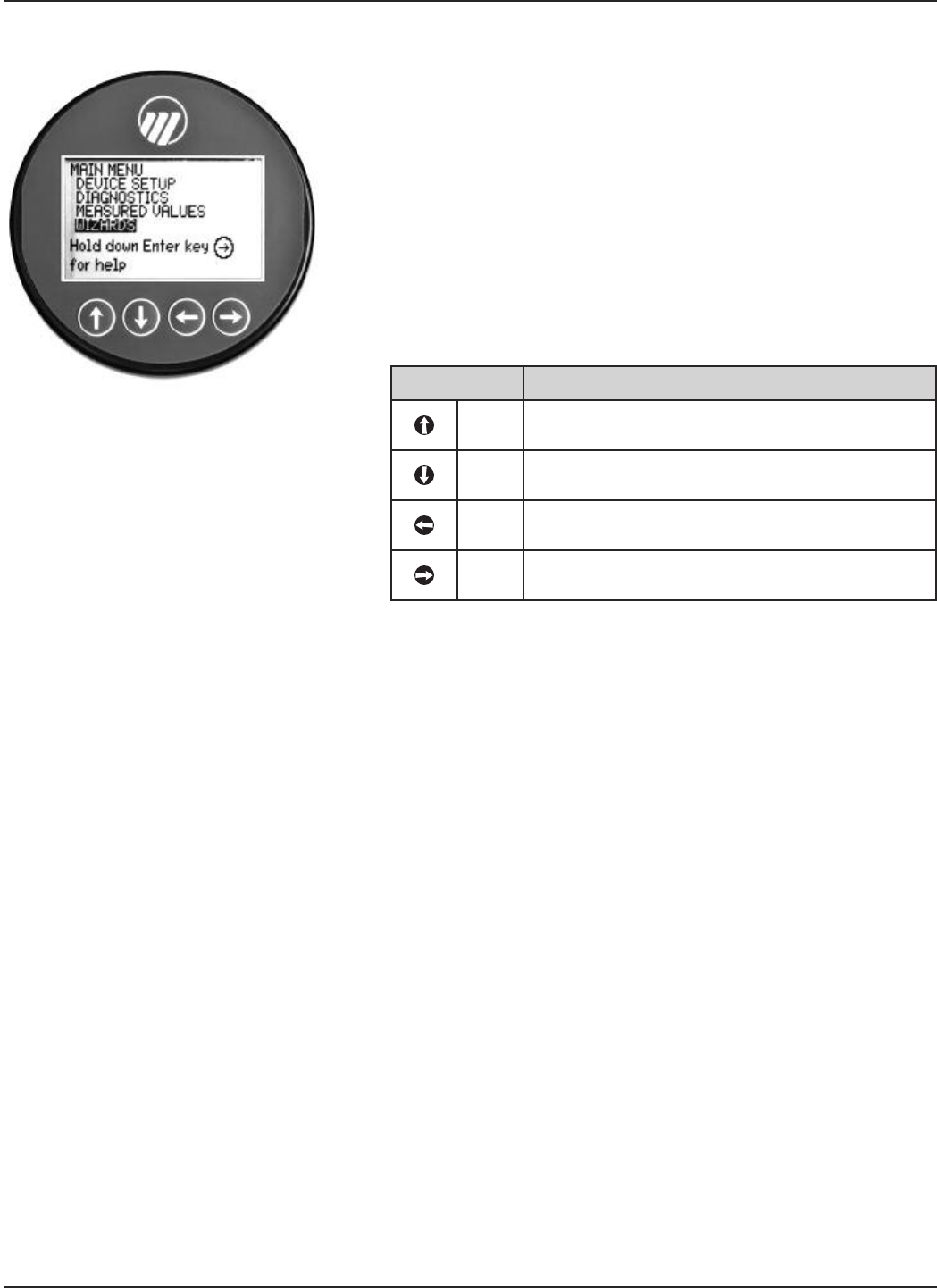
1.1.2 Configuration Information
A helpful SETUP WIZARD, which will guide you through
the simple configuration (with parameter explanations), is
available in the PULSAR Model R86. Located in the local
user interface menu under MAIN MENU/WIZARD/
SETUP WIZARD, some key information is required for
configuration. The transmitter will prompt confirmation
questions at the end of the Setup Wizard to verify operation.
Gather the information and complete the following operat-
ing parameters table before beginning configuration.
NOTE: These configuration steps are not necessary if the transmitter
was pre-configured prior to shipment.
Display Question Answer
Measurement What is the intended measurement
Type type (Level, Volume, or Flow)? _____________
System What units of measurement will be
Units used? _____________
Antenna What type of antenna is being used?
Model Select first 3 digits of model number.
(See nameplate on side of antenna.) _____________
Antenna What is maximum nozzle length for
Extension which the antenna can be used?
Select 8th digit of antenna model number.
(See nameplate on side of antenna.) _____________
Antenna Is the antenna mounting NPT, BSP,
Mount or flanged? _____________
Heat Is there a heat extension connected
Extension to the antenna? _____________
Tank Height What is the tank height? _____________
Stillwell ID What is the Inner Diameter (ID).
Enter 0 if not applicable. _____________
Dielectric What is the dielectric of the process
Range medium? _____________
Turbulence What amount of turbulence is expected? _____________
Foam What amount of foam is expected? _____________
Rate of What is the expected maximum rate
Change of level change? _____________
Primary Select Level, Volume, or Flow
Variable _____________
4 mA What is the 0% reference point for the
Setpoint 4.0 mA value? _____________
(LRV)
20 mA What is the 100% reference point for
Setpoint the 20.0 mA value? _____________
(URV)
PV Alarm What output current is desired when a
Selection failure indicator is present? _____________
Damping How much damping (averaging) is
required? Default = 1 second _____________

7
58-603 Pulsar®Model R86 Radar Transmitter
1.2 QuickStart Mounting
NOTE: Confirm the configuration style and process connection (size
and type) of the PULSAR Model R86 radar transmitter. Ensure it
matches the requirements of the installation before continuing
with the QuickStart installation.
➀Confirm the model and serial numbers on the nameplates
of PULSAR Model R86 electronics and antenna are identical.
1.2.1 Antenna
➁Carefully place the antenna into the vessel. Mount in a
location equal to 1⁄2the radius of tank top. Do not mount in
center of vessel nor closer than 18" (45 cm) of tank wall.
➂Secure the antenna to the vessel.
➃Leave the protective plastic cap in place until ready to
install the transmitter.
NOTE: Do not use sealing compound or TFE tape on antenna connec-
tion to transmitter. This connection is sealed by a Viton®O-ring.
1.2.2 Transmitter
1. Remove the protective plastic cap from the top of the
antenna and store for future use. Make sure the bottom of
the Universal connector (Teflon®) and inside of the antenna
are clean and dry. Clean with isopropyl alcohol and cotton
swabs if necessary.
2. Place the transmitter onto the antenna.
3. Rotate the transmitter so that it is in the most convenient
position for wiring, configuring, and viewing.
4. While keeping the housing aligned, tighten the large
Universal connector Hex nut to 30 ft./lbs (40 Nm) of force.
A torque wrench is highly desirable.
DO NOT LEAVE HAND TIGHT.
• Do not place insulating material around any part of the
Radar transmitter including the antenna flange.
Universal
Connector
858-603 Pulsar®Model R86 Radar Transmitter
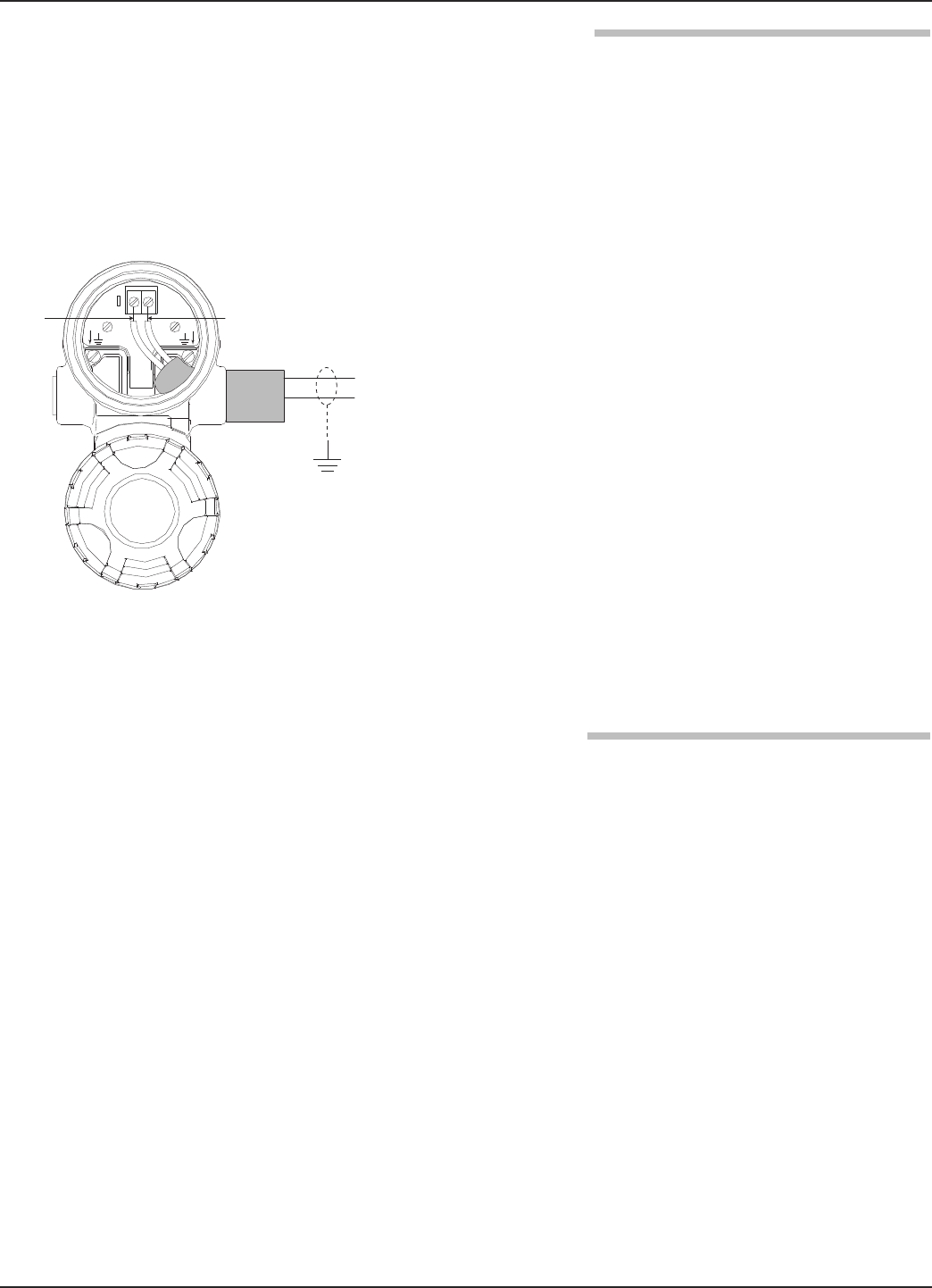
1.3 QuickStart Wiring
WARNING! Explosion hazard. Do not remove covers unless power
has been switched off or the area is known to be non-
hazardous.
NOTE: Ensure that the electrical wiring to the PULSAR Model R86
radar transmitter is complete and in compliance with all regula-
tions and codes.
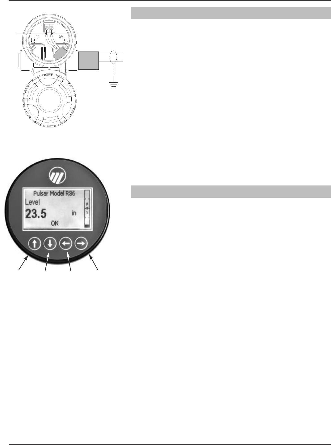
1. Remove the cover of the upper wiring compartment.
2. Attach a conduit fitting and mount the conduit plug in the
spare opening. Pull the power supply wire through the con-
duit fitting.
3. If present, connect cable shield to an earth ground at the
power supply.
4. Connect the positive supply wire to the (+) terminal and the
negative supply wire to the (-) terminal. For Explosion
Proof Installations, see Wiring, Section 2.5.3.
5. Replace the cover and tighten.
1.4 Setup Wizard – Configuration
If requested, the PULSAR Model R86 transmitter is
shipped fully pre-configured for the application and can be
installed immediately. Otherwise, the unit is shipped config-
ured with default factory values and can be easily
reconfigured in the shop. The minimum configuration
instructions follow. Use the information from the operating
parameters table before beginning configuration. See
Configuration Information, Section 1.1.2.
The Setup Wizard offers a very simple step-by-step menu
indicating the basic parameters required for a typical
application.
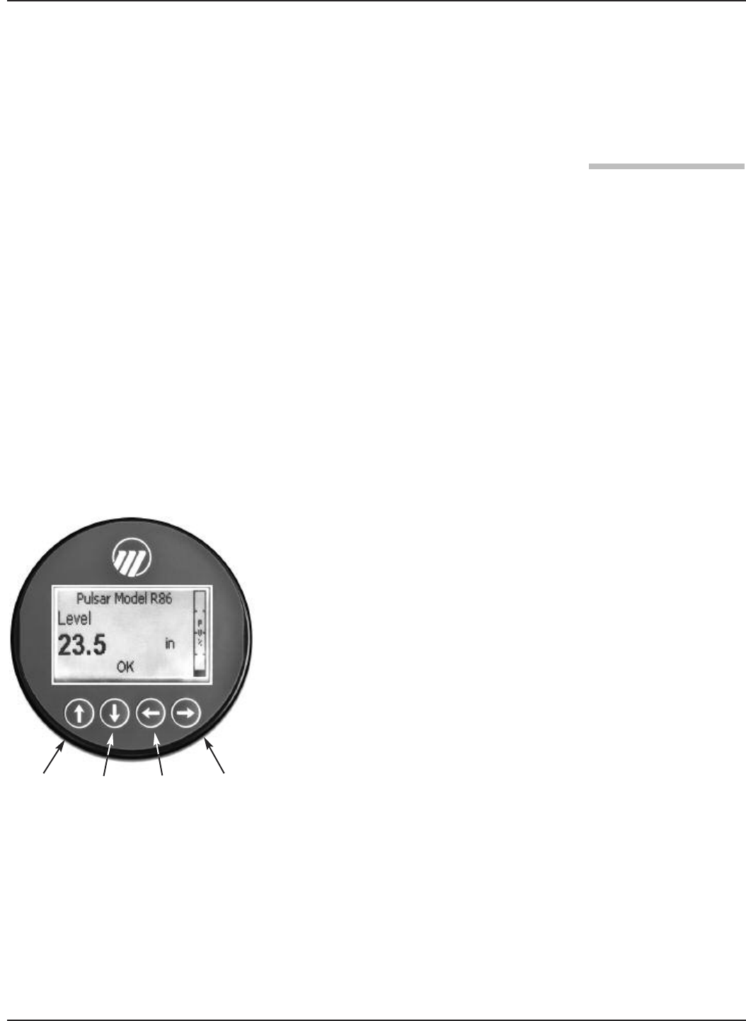
1. Apply power to the transmitter.
The graphic LCD display can be programmed to change
every two seconds to show pertinent Measured Values on
the Home Screen. For example: Level, %Output, and Loop
current can all be displayed on a rotating screen.
The LCD can also be programmed to always show just one
of the Measured Variables at all times. For example: Level
can be the only value displayed on the screen.
2. Remove the cover of the electronics compartment.
Red (+)
Black (-)
(+)
(-)
Up Down Back Enter
9
58-603 Pulsar®Model R86 Radar Transmitter
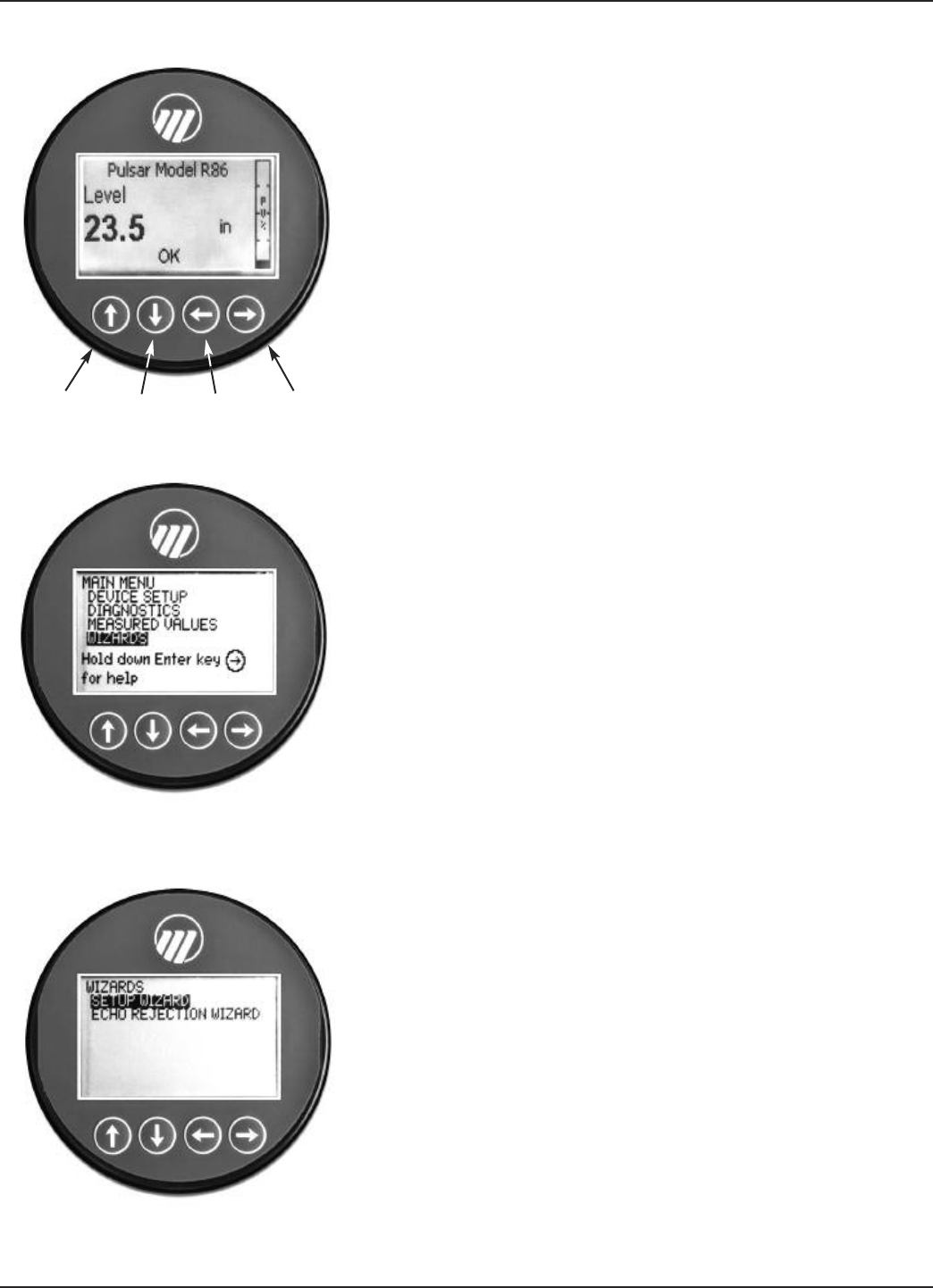
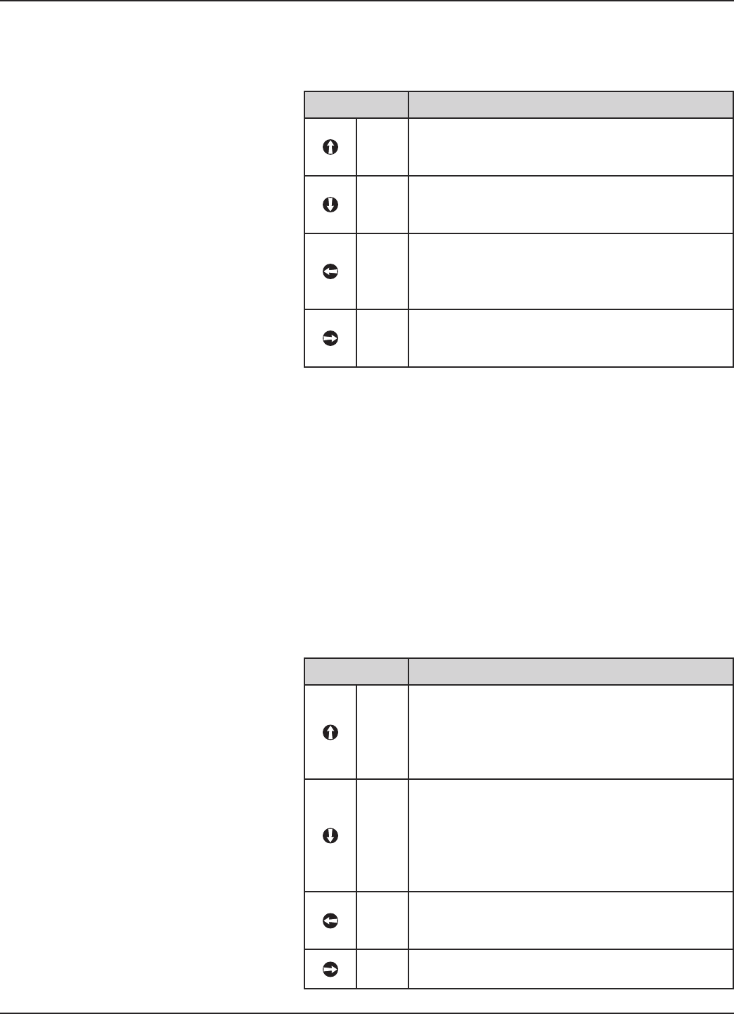
3. The push buttons offer multiple forms of functionality for
menu navigation and data entry. (See Section 2.6 for com-
plete explanation.)
UP moves up through the menu or increases a displayed
value.
DOWN moves down through the menu or decreases a
displayed value.
BACK exits a branch of the menu or exits without
accepting entered value.
ENTER enters a branch of the menu or accepts a
displayed entry.
NOTE: Holding down the ENTER key for two seconds when any menu
or parameter is highlighted will show help text in reference to
that item.
4. Press any key at the Home Screen to access the Main Menu.
5. Press ENTER with the WIZARDS menu item high-
lighted.
6. Press ENTER with the SETUP WIZARD menu item
highlighted.
The Setup Wizard shows the basic parameters, along with
Help Text to guide the procedure.
One can now quickly and easily scroll through the Setup
Wizard configuration items, changing those parameters as
required:
• Press ENTER at the highlighted parameter.
• Scroll to the desired option, then press ENTER.
• Scroll to next parameter or press BACK when
finished to exit the WIZARDS menu.
Section 1.4.1 lists and describes the nine parameters in the
WIZARDS menu.
7. After making all of the necessary changes in the WIZARDS
menu, press the BACK button three times to return to
the Home Screen.
8. The QuickStart configuration is complete. The Model R86
transmitter should be measuring and is ready for service.
➪
➪
➪
➪
➪
➪
➪
➪
➪
➪
Up Down Back Enter
STEP 4
STEP 5
STEP 6

10 58-603 Pulsar®Model R86 Radar Transmitter
Level Units Select the Units of measurement for the level output:
• Inches • Feet • Millimeters • Centimeters • Meters
Tank Height Enter tank height (in Level Units selected)
Antenna Model • RB1-x — 1½" horn
• RB2-x — 2" horn
• RB3-x — 3" horn
• RB4-x — 4" horn
Antenna Extension 0 For nozzle height ″1" (25 mm) (for threaded process connection only; refer to antenna
nameplate):
1 For nozzle height 4" (100 mm)
2 For nozzle height 8" (200 mm)
3 For nozzle height 12" (300 mm)
4 For nozzle height 24" (600 mm)
5 For nozzle height 48" (1200 mm)
6 For nozzle height 72" (1800 mm)
Antenna Mount Select the type of Antenna Mounting to the vessel (refer to antenna nameplate):
• NPT (National Pipe Thread)
• BSP (British Standard Pipe)
• Flange (ANSI or DIN)
Dielectric Range Enter the Dielectric Range for the material to be measured.
Below 1.7 (light hydrocarbons like propane and butane; stillwell only)
1.7 to 3.0 (most typical hydrocarbons)
3.0 to 10 (varying dielectric, for example: mixing tanks)
Above 10 (water-based media)
HART Only
4 mA Set Point
(LRV)
Enter the level value (0%-point) for the 4 mA point. Lower Range Value (LRV).
Refer to Section 1.4.1.1.
20 mA Set Point
(URV)
Enter the level value (100%-point) for the 20 mA point. Upper Range Value (URV).
Refer to Section 1.4.1.1.
PV Alarm
Selection
Enter the desired output state when a Failure Indicator is active.
• High (22 mA)
• Low (3.6 mA)
• Hold (hold last value is not recommended for standard configuration). Consult factory.
1.4.1 Setup Wizard Menu Options
11
58-603 Pulsar®Model R86 Radar Transmitter
1.4.1.1 Setup Wizard Numerical Data Entry
To make numerical entry changes to Tank Height:
UP moves up to the next highest digit (0,1,2,3,....,9 or
the decimal point).
If held down the digits scroll until the push button is
released.
DOWN moves up to the next lowest digit (0,1,2,3,....,9
or the decimal point). If held down the digits scroll until
the push button is released.
BACK moves the cursor to the left and deletes a digit.
If the cursor is already at the leftmost position, then the
screen is exited without changing the previously saved
value.
ENTER Moves the cursor to the right. If the cursor is
located at a blank character position, the new value is
saved.
Scrolling further in the WIZARDS menu results in the
remaining parameters appearing one by one, with the pres-
ent highlighted value shown at the bottom of the screen.
BACK returns to the previous menu without changing
the original value, which is immediately redisplayed.
ENTER accepts the displayed value and returns to the
previous menu.
➪
➪
➪
➪
➪
➪
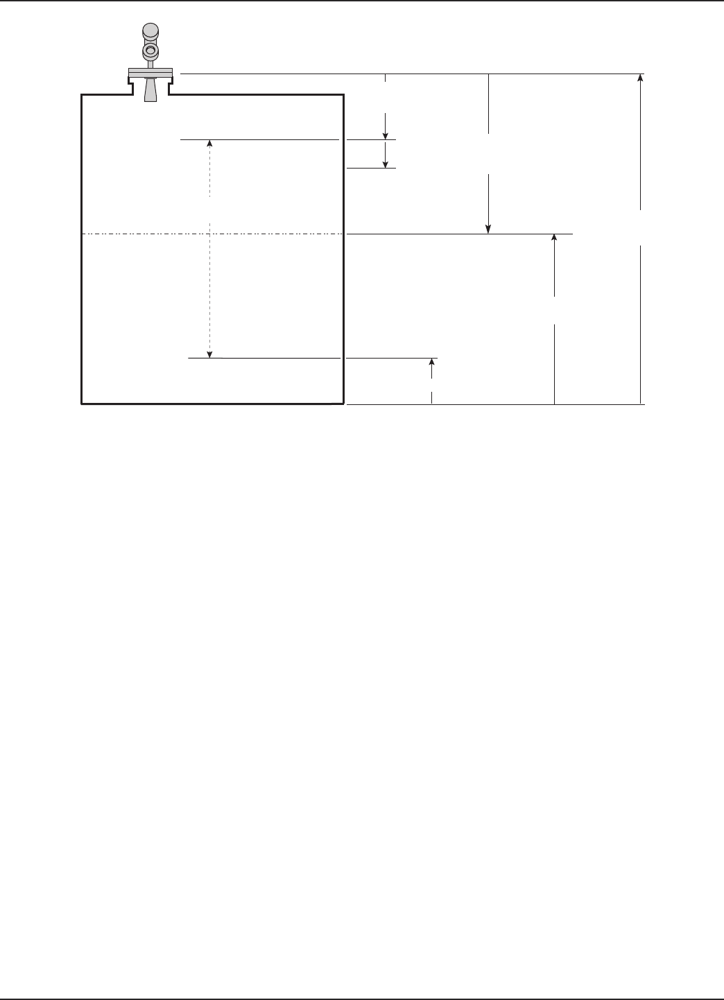
Tank
Height
Sensor Reference Point
Safety
Zone
Bottom Blocking Distance
Measurement
Region
Sensor
Level
Distance
Level = Tank Height – Distance
Top Blocking
Distance

12 58-603 Pulsar®Model R86 Radar Transmitter
2.0 Complete Installation
This section provides detailed procedures for properly
installing, wiring, configuring, and, as needed, troubleshoot-
ing the PULSAR Model R86 Radar Level Transmitter.
2.1 Unpacking
Unpack the instrument carefully. Make sure all components
have been removed from the packing material. Check all
contents against the packing slip and report any discrepancies
to the factory.
Before proceeding with the installation, do the following:
• Inspect all components for damage. Report any damage to
the carrier within 24 hours.
• Make sure the nameplate model number on the antenna and
transmitter agree with the packing slip and purchase order.
• To avoid moisture ingress in the housing, covers should be
fully tightened at all times. For the same reason, plugs
should remain properly installed in the cable entries until
replaced with a cable gland
• Record the model and serial numbers for future reference
when ordering parts.
2.2 Electrostatic Discharge (ESD)
Handling Procedure
MAGNETROL electronic instruments are manufactured to
the highest quality standards. These instruments use electronic
components that may be damaged by static electricity present
in most work environments.
The following steps are recommended to reduce the risk of
component failure due to electrostatic discharge.
• Ship and store circuit boards in anti-static bags. If an anti-
static bag is not available, wrap the board in aluminum foil.
Do not place boards on foam packing materials.
• Use a grounding wrist strap when installing and removing
circuit boards. A grounded workstation is recommended.
• Handle circuit boards only by the edges. Do not touch
components or connector pins.
• Make sure that all electrical connections are completely
made and none are partial or floating. Ground all equip-
ment to a good, earth ground
WARNING! Potential electrostatic charging hazard. Do not rub
with dry cloth.
Model Number
Serial Number

13
58-603 Pulsar®Model R86 Radar Transmitter
2.3 Before You Begin
2.3.1 Site Preparation
Each PULSAR Model R86 Radar transmitter/antenna is
built to match the physical specifications of the required
installation. Ensure that the antenna process connection is
correct for the threaded or flanged mounting on the vessel
where the transmitter will be placed. See Mounting,
Section 2.4.
Ensure that all local, state, and federal regulations and
guidelines are observed. See Wiring, Section 2.5.
Ensure that the wiring between the power supply and
PULSAR Model R86 Radar transmitter is complete and
correct for the type of installation. See Specifications,
Section 3.7.
2.3.2 Equipment and Tools
No special tools are required. The following items are
recommended:
• Threaded antenna and process connection. . . . 2" (50 mm)
• Transmitter/antenna connection. . . . . 13⁄4" (44 mm) wrench
• Transmitter adjustment. . . . . . . . . . . 11⁄8" (28 mm) wrench
3⁄32" Hex wrench
• Torque wrench. . . . . . . . . . . . . . . . . . . . . . highly desirable
• Flat-blade screwdriver
• Digital multimeter or volt/ammeter. . . . . . . . . . . Optional
• 24 VDC (23 mA) power supply. . . . . . . . . . . . . . Optional
2.3.3 Operational Considerations
Radar applications are characterized by three basic condi-
tions;
• Dielectric (process medium)
• Distance (measuring range)
• Disturbances (turbulence, foam, false targets, multiple
reflections and rate of change).
The PULSAR Model R86 Radar transmitter is offered with
a horn antenna configuration—Horn (1½", 2", 3", 4").
Ideally, if the installation allows, the 4" (DN100) horn
antenna should be used to ensure the best possible perform-
ance in all operational conditions.
14 58-603 Pulsar®Model R86 Radar Transmitter
2.3.3.1 Maximum Distance
The chart below shows the maximum measuring range
(Distance) of each antenna based on fundamental condi-
tions of Dielectric, Distance and Turbulence. Distance is
measured from the Sensor Reference Point (bottom of NPT
thread, top of BSP thread or face of a flange).
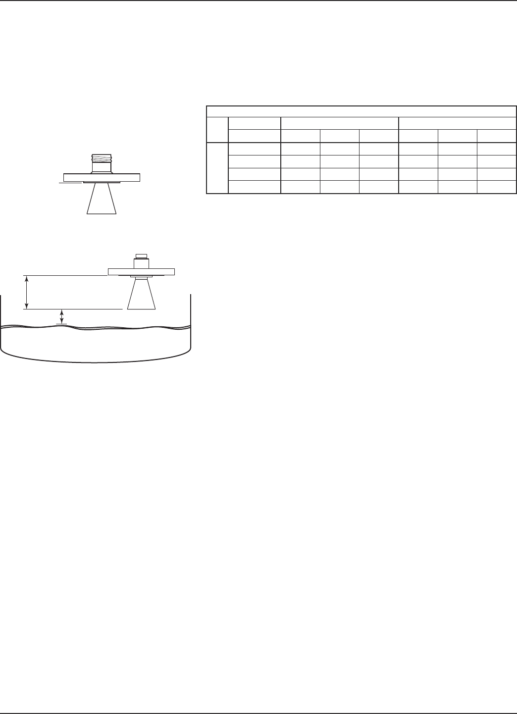
2.3.3.2 Minimum Distance
If the liquid level is allowed onto the antenna, noise and
media build-up drastically decrease reliable measurement.
Liquid should not be allowed closer than two inches
(50 mm) from the bottom of the antenna or 12 inches
(300 mm) from the sensor reference point, whichever is
greater.
2.3.3.3 Problematic Applications; GWR Alternative
Some applications can be problematic for Non- Contact
Radar. For these, Guided Wave Radar is recommended:
• Extremely low dielectric media (εr<1.7)
• Stillwells, standpipes, bridles, cages and bypass columns.
• Very weak reflections from the liquid surface (particularly
during turbulence) can cause poor performance.
• Tanks heavily cluttered with false targets (mixers, pumps,
ladders, pipes, etc.)
• During times of very low liquid levels of low dielectric media,
the metal tank bottom may be detected which can deterio-
rate performance.
• Foam can either absorb or reflect the microwave energy
depending upon the depth, dielectric, density and wall
thickness of the bubbles. Due to typical variations in the
amount (depth) of foam, it is impossible to quantify per-
formance. It may be possible to receive most, some or none
of the transmitted energy.
• When measurement close to flange is critical
Extremely high liquid levels (Overflow) conditions when
liquid very near the antenna can cause erroneous read-
ings and measurement failure.
• Interface applications
Refer to Eclipse®Model 706 bulletin 57-106 for
additional information.
2" (50 mm)
12" (300 mm)
or
Sensor
Reference
Point
ANSI or DIN Welded Flange
R86 Maximum Recommended Measuring Range in feet (meters)
Turbulence None or Light Turbulence Medium or Heavy
Dielectric > 1.7 –3 3 – 10 10 – 100 1.7 –3 3 – 10 10 – 100
Antenna
Type
11⁄2" Horn 30 (9) 40 (12) 60 (18) 10 (3) 16 (5) 26 (8)
2" Horn 33 (10) 49 (15) 66 (20) 10 (3) 20 (6) 33 (10)
3" Horn 50 (15) 66 (20) 98 (30) 13 (4) 30 (9) 40 (12)
4" Horn 66 (20) 98 (30) 130 (40) 23 (7) 40 (12) 50 (15)
15
58-603 Pulsar®Model R86 Radar Transmitter
2.4 Mounting
The PULSAR Model R86 Radar transmitter can be mount-
ed to a vessel using a variety of process connections.
Generally, either a threaded or flanged connection is used.
For information about the sizes and types of connections
available, see Antenna Model Numbers, Section 3.8.2.
2.4.1 Installing the Antenna
Before installing, ensure that:
•Model and Serial numbers on the nameplates of the
PULSAR Model R86transmitter and antenna are identical.
•Process temperature, pressure, dielectric, turbulence and
distance are within the antenna specifications for the
installation.
•Insulating material is not placed around any part of the
Radar transmitter including the antenna flange.
•Protective cap is kept on the antenna if the transmitter is to
be installed at a later time.
•Antenna is being mounted in the optimal location.See fol-
lowing sections: Location, Beam Angle, Obstructions and
Nozzles for specific information.
•If the liquid level comes in contact with the antenna, noise
and media buildup drastically decrease reliable measure-
ment. Liquid should not be allowed closer than two inches
(50 mm) from the bottom of the antenna or 12 inches (300
mm) from the sensor reference point, whichever is greater.
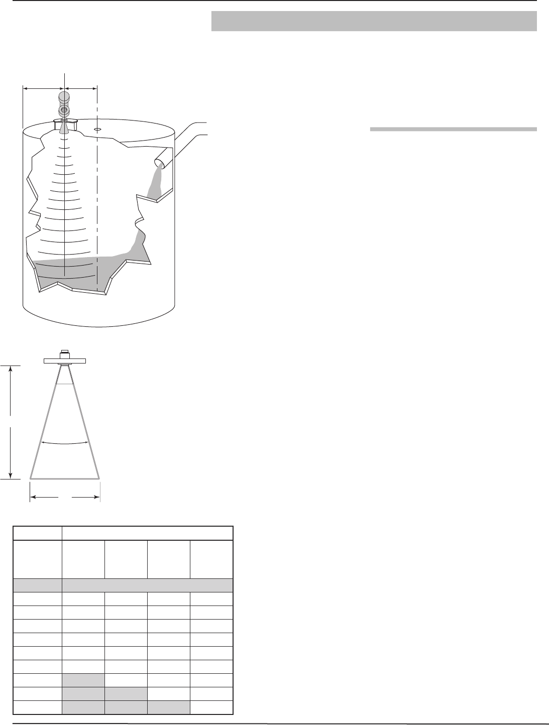
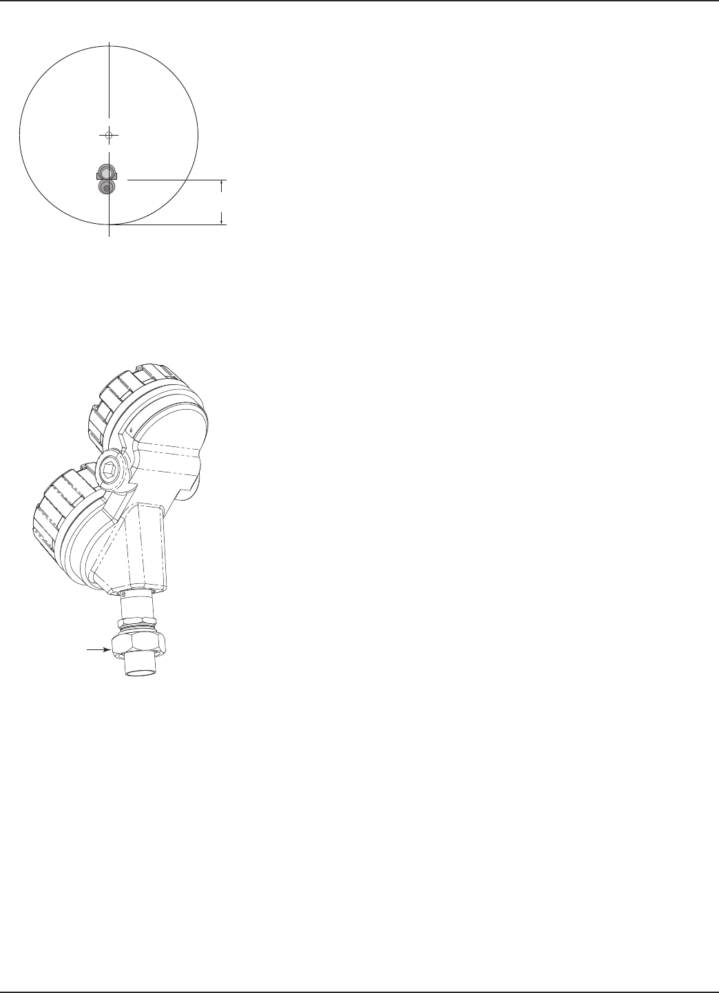
2.4.1.1Location
Ideally, the Radar transmitter should be mounted providing
an unobstructed signal path to the liquid surface where it
should illuminate (with microwave energy) the largest,
possible surface area. See Section 2.4.1.2, Beam Angle.
Unavoidable obstacles will produce reflections that must be
minimized during field configuration. See Section 3.3.3,
Echo Rejection. Mount in a location equal to 1⁄2the radius
of tank top. Do not mount in center of vessel nor closer
than 18" (45 cm) of tank wall. Contact Magnetrol
Technical Support when mounting closer than 18" (45 cm)
is required.
2.4.1.2Beam Angle
The various horn antennas exhibit slightly different beam pat-
terns. Ideally, the beam pattern should illuminate with
microwave beam the maximum liquid surface with minimum
contact with other objects in the vessel including the tank wall.
Use the chart at left to determine the optimum installation
location.
1/2
Radius
> 18"
(45 cm)
D
W
∝
Beam Spread, W @-3dB; ft (m)
Antenna
Beam Angle
(∝)
11⁄2" Horn
20°
2" Horn
18°
3" Horn
11°
4" Horn
9°
Distance, D
10 (3) 3.5 (1.1) 3.2 (1.0) 1.9 (0.6) 1.6 (0.5)
20 (6) 7.1 (2.1) 6.3 (1.9) 3.9 (1.2) 3.1 (0.9)
30 (9) 10.6 (3.2) 9.5 (2.9) 5.8 (1.7) 4.7 (1.4)
40 (12) 14.1 (4.2) 12.7 (3.8) 7.7 (2.3) 6.3 (1.9)
50 (15) 17.6 (5.3) 15.8 (4.8) 9.6 (2.9) 7.9 (2.4)
60 (18) 21.2 (6.3) 19.0 (5.7) 11.6 (3.5) 9.4 (2.8)
65 (20) 20.6 (6.3) 12.5 (3.9) 10.2 (3.1)
98 (30) 18.9 (5.8) 15.4 (4.7)
130 (40) 20.5 (6.3)
16 58-603 Pulsar®Model R86 Radar Transmitter
2.4.1.3 Obstructions
Almost any object that falls within the beam pattern will
cause reflections that may be misinterpreted as a false liquid
level. Although PULSAR Model R86 has a powerful Echo
Rejection routine, all possible precautions should be taken
to minimize false target reflections with proper installation
and orientation. Refer to section 2.4.2.3 for additional
information.
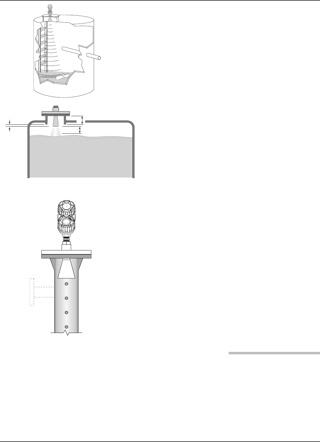
2.4.1.4 Nozzles
Improper installation in a nozzle can create “ringing” that
will adversely affect measurement. The antenna should
always be mounted so the active section of the antenna is a
minimum of 0.5" (12mm) outside the nozzle. Antenna
extensions are offered to allow the PULSAR Model R86
transmitter to work reliably in nozzles up to 72" (1.8
meter). See Section 3.7.6 for dimensional drawings of all
antenna designs including nozzle extensions.
Be sure to include any nozzle distance extending within
the vessel.
2.4.1.5 Standpipes and Stillwells
The PULSAR Model R86 can be mounted in a standpipe
or stillwell but certain items must be considered:
• Metal stillwells only: Sizes 11⁄2–4 inches (38–100 mm).
• Diameter must be consistent throughout length; no reducers
or gaps.
• Stillwell length must cover complete range of
measurement (i.e., liquid must be in stillwell).
• Welds should be smooth.
• Vents: holes <0.125" (3 mm) diameter,
slots <0.125" (3 mm) width.
• If an isolation valve is used, it must be a full port
ball valve with an I.D. equal to the pipe diameter.
• Configuration must include a non-zero entry for
PIPE I.D parameter.
2.4.2 Installing the Transmitter
• Remove the protective plastic cap from the top of antenna.
Store the cap in a safe place in case the transmitter has to be
removed later.
• Carefully place the transmitter on the antenna.
• Rotate the transmitter to face the most convenient direction
for wiring, configuration and viewing.
• Do not place insulating material around any part of the
radar transmitter including the antenna flange.
0.50" (13 mm)
Minimum
2" (50 mm)
" L " Dimension (Nozzle Height)
PULSAR Model R86 Mounted in
Stillwell (Bridle)
17
58-603 Pulsar®Model R86 Radar Transmitter
NOTE: ALWAYS RUN THE ECHO REJECTION ROUTINE AFTER MAKING
CHANGES TO MENU ITEMS (Antenna Model, Antenna
Extension, Antenna Mount, Tank Height, Blocking Distance,
Dielectric, Turbulence, Rate of Change, Foam).
2.4.2.1 Low Echo Margin
Echo Margin is a parameter that, when used with Echo
Strength, can be a very useful troubleshooting tool. It is
defined as a numeric value that is related to the strength of
the target peak relative to the Level Threshold or competing
waveform features, i.e., noise.
Echo Loss: If the Level signal is lost repeatedly at a specific
point in the vessel, it is usually a symptom of multipath
(side-wall) reflections causing cancellation by returning to
the transmitter exactly 180° out of phase with the actual
Level signal. This can be improved by applying the follow-
ing procedure:
• Scroll to Display Config Menu under Device Setup. Scroll
down to Echo Strength and Echo Margin and change the
settings from Hide to View. This will allow you to view
these values from the home screen.
• Bring the Level up (or down) to the exact point where the
signal is repeatedly lost. Monitor the Echo Margin value as
this point is being approached. The Echo Margin value will
degrade to a low point before it begins to increase.
• Refer to Section 4.4 for additional information.
1/2 Radius
Top View
Mounted 1⁄2radius
Universal
Connector
18 58-603 Pulsar®Model R86 Radar Transmitter
Red (+)
Black (-)
(+)
(-)
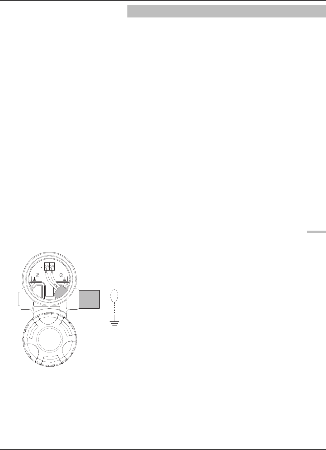
2.5 Wiring
Caution: HART versions of the PULSAR Model R86 transmitter
operate at voltages of 11–36 VDC. FOUNDATION fieldbus™
versions operate at 9–17.5 VDC. Higher voltages will dam-
age the transmitter.
Wiring connections between the power supply and the
PULSAR Model R86 Radar Transmitter should be made
using 18–22 AWG (0.5–1mm2) shielded twisted pair
instrument cable. Connections are made to the terminal
strip and the ground connections within the top enclosure
compartment.
The instructions for wiring the PULSAR Model R86
transmitter depend on the application:
• General Purpose or Non-Incendive (Cl I, Div. 2)
• Intrinsically Safe
• Explosion Proof
WARNING! Explosion hazard. Do not disconnect equipment unless
power has been switched off or the area is known to be
non-hazardous.
To avoid moisture ingress in the housing, covers should be
fully tightened at all times. For the same reason, cable
gland and plugs should be properly installed in the cable
entries.
2.5.1 General Purpose or Non-incendive (Cl I, Div. 2)
A general purpose installation does not have flammable
media present.
Areas rated Non-Incendive (Cl I, Div. 2) have flammable
media present only under abnormal conditions.
No special electrical connections are required.
Caution: If flammable media is contained in the vessel, the trans-
mitter must be installed per Class I, Div 1 standards of
area classification.
To install General Purpose or Non-Incendive wiring:
1. Remove the cover from the wiring compartment of the
transmitter. Install the conduit plug in the unused opening
and use PTFE tape/sealant to ensure a liquid-tight
connection.
2. Install a conduit fitting and pull the supply wires.
3. Connect shield to an earth ground at power supply.
4. Connect an earth ground wire to the nearest green ground
screw (not shown in illustration).
5. Connect the positive supply wire to the (+) terminal and
the negative supply wire to the (-) terminal.
6. Replace and tighten the cover to the transmitter wiring
compartment before applying power.
19
58-603 Pulsar®Model R86 Radar Transmitter
2.5.2 Intrinsically Safe
An Intrinsically Safe (IS) installation potentially has flam-
mable media present. An approved IS barrier must be
installed in the non-hazardous (safe) area to limit the avail-
able energy out to the hazardous area.
See Agency Drawing – Intrinsically Safe Installation,
Section 3.5.1.
To install Intrinsically Safe wiring:
1. Ensure that the IS barrier is properly installed in the safe
area (refer to local plant or facility procedures). Complete
the wiring from the power supply to the barrier and from
the barrier to the PULSAR Model R86 transmitter.
2. Remove the cover from the wiring compartment of the
transmitter. Install the conduit plug in the unused opening
and use PTFE tape/sealant to ensure a liquid-tight
connection.
3. Install a conduit fitting and pull the supply wires.
4. Connect shield to an earth ground at power supply.
5. Connect an earth ground wire to the nearest green ground
screw (not shown in illustration).
6. Connect the positive supply wire to the (+) terminal and
the negative supply wire to the (-) terminal.
7. Replace and tighten the cover to the wiring compartment
of the transmitter before applying power.
2.5.3 Explosion Proof
Explosion Proof (also referred to as XP or flameproof) is
another method of designing equipment for installation
into hazardous areas. A hazardous location is an area in
which flammable gases or vapors are (or may be) present
in the air in quantities sufficient to produce explosive or
ignitable mixtures.
The wiring for the transmitter must be contained in
Explosion Proof conduit extending into the safe area.
• Due to the specialized design of the PULSAR Model R86
transmitter, no Explosion Proof conduit fitting (EY seal) is
required within 18" of the transmitter.
• An Explosion Proof conduit fitting (EY seal) is required
between the hazardous and safe areas. See Agency
Specifications, Section 3.5.
Red (+)
Black (-)
(+)
(-)

20 58-603 Pulsar®Model R86 Radar Transmitter
To install an Explosion Proof transmitter:
1. Install Explosion Proof conduit from the safe area to the
conduit connection of the PULSAR Model R86 transmit-
ter (refer to local plant or facility procedures).
2. Remove the cover from the wiring compartment of the
transmitter.
3. Connect shield to an earth ground at the power supply.
4. Connect an Earth ground wire to the nearest green ground
screw per local electrical code (not shown in illustration).
5. Connect the positive supply wire to the (+) terminal and
the negative supply wire to the (-) terminal.
6. Replace and tighten the cover to the wiring compartment
of the transmitter before applying power.
2.6 Configuring the Transmitter
Although the PULSAR Model R86 transmitter can be
delivered pre-configured from the factory, it can also be
easily reconfigured in the shop or at the installation using
the local LCD/Keypad or PACTware/DTM. Bench config-
uration provides a convenient and efficient way to set up
the transmitter before going to the tank site to complete
the installation.
Before configuring any transmitter, collect all operating
parameters information (refer to Section 1.1.2).
Apply power to the transmitter and follow the step-by-step
procedures for the menu-driven transmitter display. Refer
to Sections 2.6.2 and 2.6.4.
Information on configuring the transmitter using a HART
communicator is given in Section 2.7, Configuration
Using HART.
Refer to I/O manual 58-641 for information on
FOUNDATION fieldbus output.
2.6.1 Bench Configuration
The PULSAR Model R86 transmitter can be easily config-
ured at a test bench by connecting a standard 24 VDC
power supply directly to the transmitter terminals as
shown in the accompanying diagram. An optional digital
multimeter is shown in the event that mA current meas-
urements are desired.
NOTE: Current measurements taken at these test points are an
approximate value. Accurate current readings should be
taken with the digital multimeter directly in series with the
loop.
+
–
Power Supply
24 VDC
–
+
(–) negative
(+) positive
Test
Current Meter
G.P./I.S./Explosion Proof Model
21
58-603 Pulsar®Model R86 Radar Transmitter
NOTE: When using a HART communicator for configuration, a mini-
mum 250-ohm line load resistance is required. Refer to your
HART communicator manual for additional information.
NOTE: The transmitter can be configured without the antenna
attached. Disregard any diagnostic indicators that may
appear during that time.
2.6.2 Menu Traversal and Data Entry
The four push buttons offer various forms of functionality
for navigation and data entry.
The PULSAR Model R86 user interface is hierarchical in
nature, best described as a tree structure. Each level in the
tree contains one or more items. Items are either menu
labels or parameter names.
• Menu labels are presented in all capital letters
• Parameters are capital words
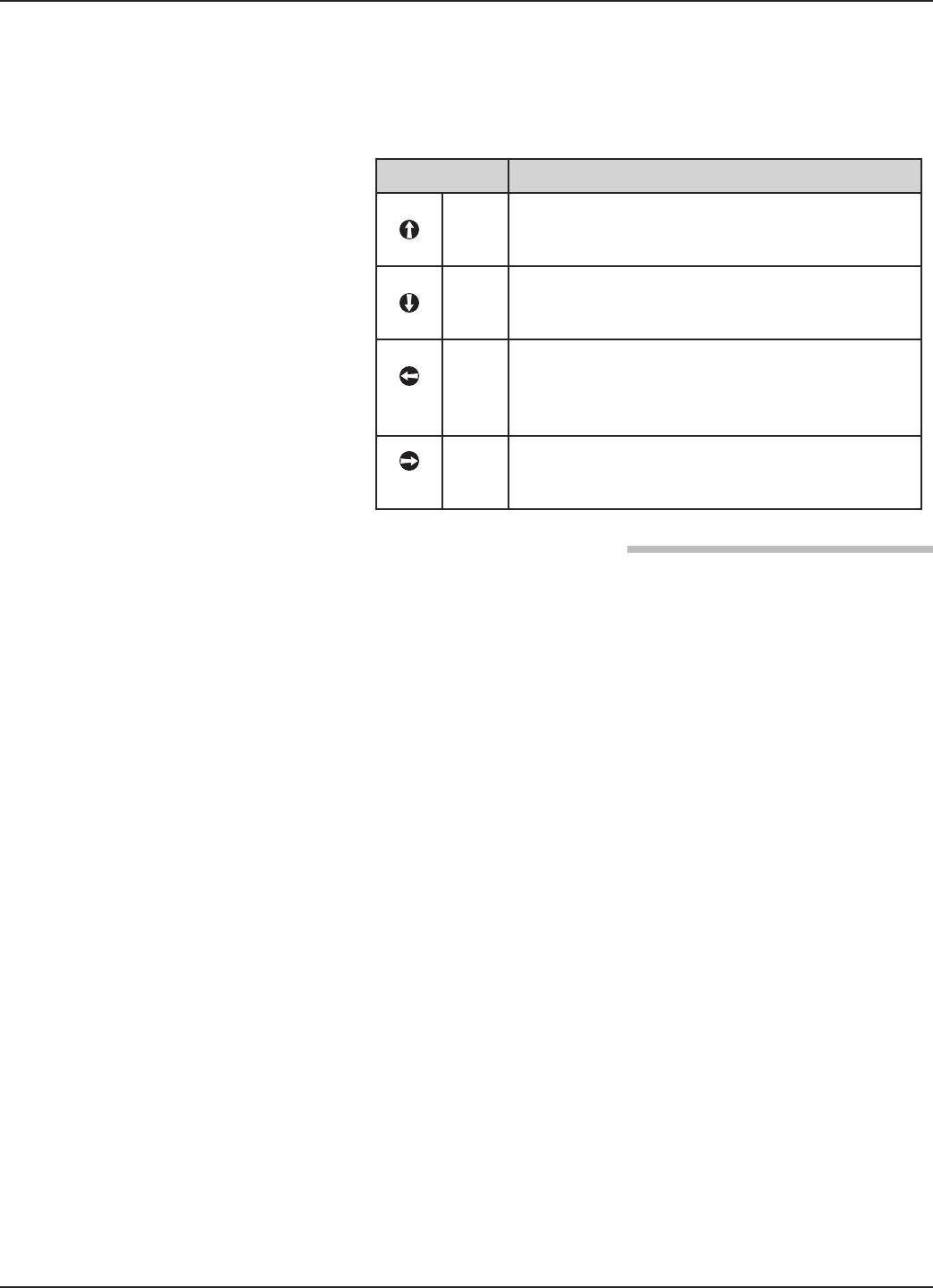
2.6.2.1 Navigating the Menu
UP moves to the previous item in the menu branch.
DOWN moves to the next item in the menu branch.
BACK moves back one level to the previous (higher)
branch item.
ENTER enters into the lower level branch or switches
to the entry mode. Holding the ENTER down on any
highlighted menu name or parameter will show help
text for that item.
2.6.2.2 Data Selection
This method is used for selecting configuration data from
a specific list.
UP and DOWN to navigate the menu and high-
light the item of interest
ENTER allows modification of that selection
UP and DOWN to choose new data selection
ENTER to confirm selection
Use BACK (Escape) key at any time to abort the pro-
cedure and escape to previous branch item
➪
➪
➪
➪
➪
➪
➪
➪
➪
➪
➪
Up Down Back Enter
22 58-603 Pulsar®Model R86 Radar Transmitter
2.6.2.3 Entering Numeric Data Using Digit Entry
This method is used to input numeric data, e.g., Tank
Height, 4 mA setpoint and 20 mA setpoint.
All numeric values are left-justified, and new values are
entered from left to right. A decimal point can be
entered after the first digit is entered, such that .9 is
entered as 0.9.
Some configuration parameters can have a negative
value. In this case, the leftmost position is reversed for
the sign (either "-" for a negative value, or "+" for a pos-
itive value).
2.6.2.4 Entering Numeric Data Using Increment/Decrement
Use this method to input the following data into
parameters such as Damping and Failure Alarm.
Push button Keystroke Action
Up
Moves up to the next highest digit (0,1,2,3,....,9
or decimal point). If held down the digits scroll
until the push button is released.
Down
Moves up to the next lowest digit (0,1,2,3,....,9 or
decimal point). If held down the digits scroll until
the push button is released.
Back
Moves the cursor to the left and deletes a digit. If
the cursor is already at the leftmost position,
then the screen is exited without changing the
previously saved value.
Enter
Moves the cursor to the right. If the cursor is
located at a blank character position, the new
value is saved.
Push button Keystroke Action
Up
Increments the displayed value. If held down
the digits scroll until the push button is released.
Depending on which screen is being revised, the
increment amount may increase by a factor of 10
after the value has been incremented 10 times.
Down
Decrements the displayed value. If held down the
digits scroll until the push button is released.
Depending on which screen is being revised, the
decrement amount may increase by a factor of
10 after the value has been decremented 10
times.
Back
Returns to the previous menu without changing
the original value, which is immediately redis-
played.
Enter Accepts the displayed value and returns to the
previous menu.
23
58-603 Pulsar®Model R86 Radar Transmitter
2.6.2.5 Entering Character Data
This method is used for parameters requiring alphanumeric
character entry, such as for entering tags, etc.
General Menu Notes:
2.6.3 Password Protection
The PULSAR Model R86 transmitter has three levels of
password protection to restrict access to certain portions of
the menu structure that affect the operation of the system.
User Password
The User Password allows the customer to limit access to
the basic configuration parameters.
The default User Password installed in the transmitter at
the factory is 0. With a password of 0, the transmitter is no
longer password protected and any value in the basic user
menus can be adjusted without entering a confirming
password.
The user password can be changed to any numerical value
up to 59999. When the transmitter is programmed for
password protection, a password is required whenever
configuration values are changed.
NOTE: If a User Password is not known or has been misplaced, the
menu item New Password in the DEVICE SETUP/ADVANCED
CONFIG menu displays an encrypted value representing the
present password. Contact Technical Support with this
encrypted password to retrieve the original User Password.
Push button Keystroke Action
Up
Moves to the previous character (Z...Y...X...W).
If held down, the characters scroll until the push
button is released.
Down
Moves to the next item character (A...B...C...D).
If held down, the characters scroll until the push
button is released.
Back
Moves the cursor back to the left. If the cursor is
already at the leftmost position, then the screen
is exited without changing the original tag char-
acters.
Enter
Moves the cursor forward to the right. If the
cursor is at the rightmost position, then the
new tag is saved.

24 58-603 Pulsar®Model R86 Radar Transmitter
Advanced Password
Certain portions of the menu structure that contain more
advanced parameters are further protected by an Advanced
Password.
This password will be provided, when necessary, by Factory
technical support.
Factory Password
Calibration-related and other factory settings are further
protected by a Factory Password.
2.6.4 Model R86 Menu: Step-By-Step Procedure
NOTE: Context-sensitive HELP is available for all menu and parameter
items. With the item highlighted, hold down the ➪ENTER key
for two seconds. Use UP and DOWN for navigation.
The tables in Section 2.6.5 provide a complete explanation
of the software menus displayed by the PULSAR Model
R86 transmitter. The menu layout is similar between the
local Keypad/LCD interface, the DD, and the DTM.
Use these tables as a step-by-step guide to configure the
transmitter based on the desired measurement type from the
following selections:
• Level Only
• Volume & Level
• Flow
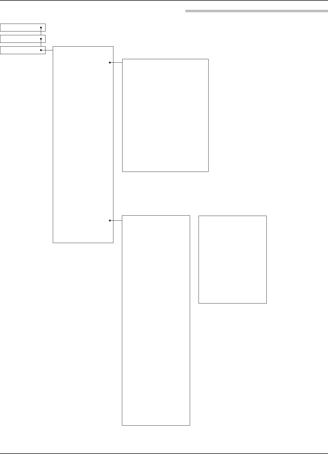
HOME SCREEN
The Home Screen consists of a “slide show” sequence of
Measured Values screens which are rotated at 2-second
intervals. Each Home Measured Value screen can present up
to four information items:
• HART®Tag
• Measured Value
Label, Numerical Value, Units
• Status
Will be displayed as text or optionally with NAMUR
NE 107 symbol
• Primary Value Bar Graph (shown in %)
The Home Screen presentation can be customized by view-
ing or hiding some of these items. See DISPLAY CONFIG
under the DEVICE SETUP menu in Section 2.6.5 —
Configuration Menu.
At left is an example of a Home Screen for a Model R86
configured for a Level Only application.
➪
➪
Up Down Back Enter
25
58-603 Pulsar®Model R86 Radar Transmitter
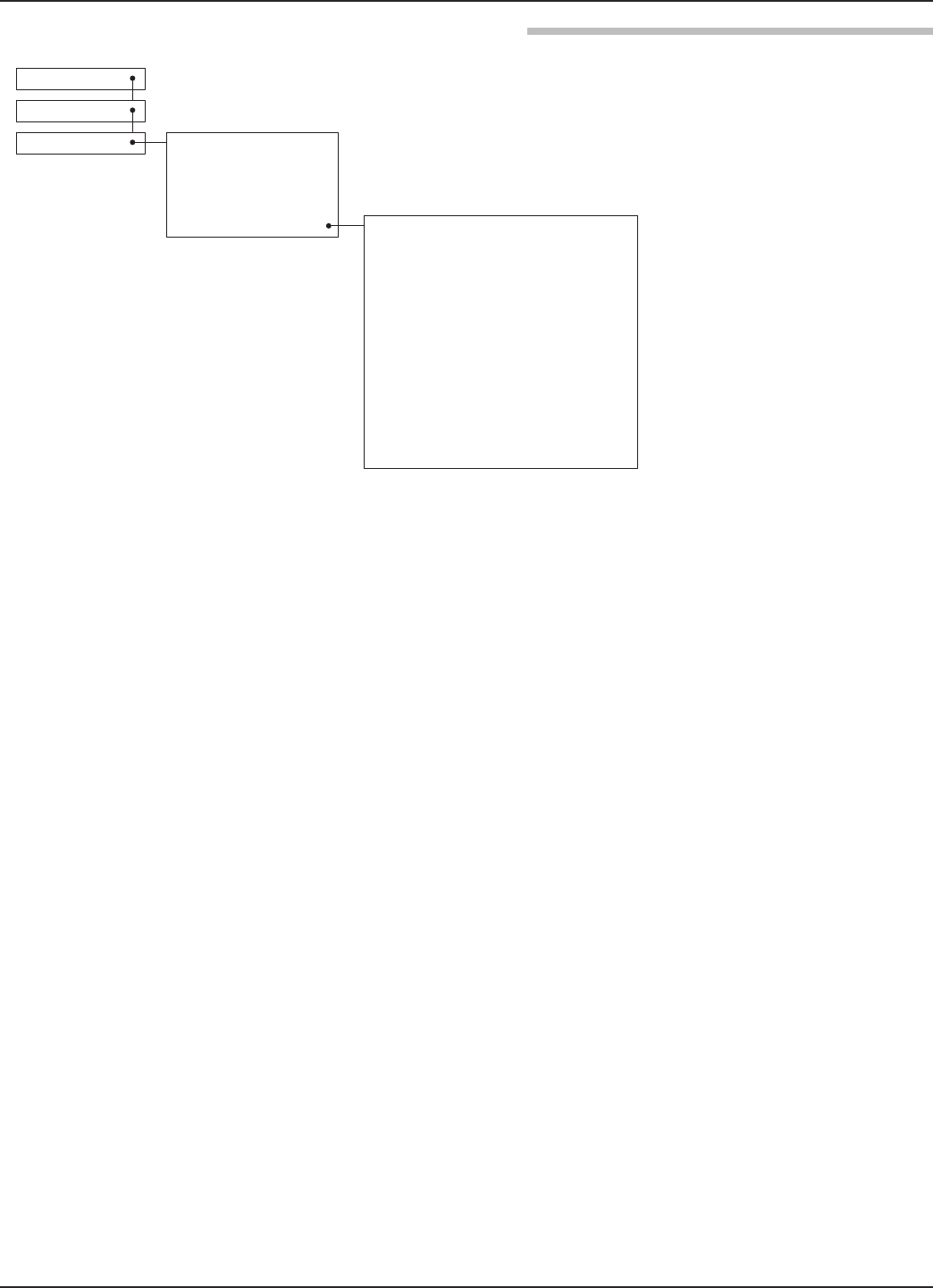
MAIN MENU
Pressing any key on the Home Screen will present the Main
Menu, consisting of three basic menu labels shown in all
capital letters.
• DEVICE SETUP
• DIAGNOSTICS
• MEASURED VALUES
• WIZARDS
As shown, the reverse video represents a cursor identifying
the selected item, which will appear in reverse video on the
LCD. The actions of the keys at this point are:
NOTES: 1. Items and parameters that are shown in lower level menus
will depend on the Measurement Type chosen. Those
parameter not applicable to the present Measurement Type
will be hidden.
2. Holding down the Enter key when the cursor is highlighted
over a parameter or menu will provide additional information
about that item.
Push button Keystroke Action
Up No action as the cursor is already at the first
item in the MAIN MENU
Down Moves the cursor to DIAGNOSTICS
Back Moves back to HOME SCREEN, the level
above MAIN MENU
Enter Presents the selected item, DEVICE SETUP
26 58-603 Pulsar®Model R86 Radar Transmitter
R86 Level Model
Tank
Height
Sensor Reference Point
Safety
Zone
Bottom Blocking Distance
Measurement
Region
Sensor
Level
Distance
Level = Tank Height – Distance
Top Blocking
Distance
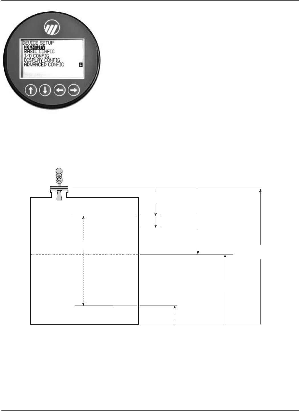
DEVICE SETUP
Choosing DEVICE SETUP from the MAIN MENU will
result in an LCD presentation as shown at left.
The small down arrow shown at the right hand side of the
screen is the indication that more items are available below
and can be accessed by pressing the DOWN key.
Section 2.6.5 shows the entire tree menu for the Model R86
DEVICE SETUP Menu.
DIAGNOSTICS
Refer to Section 3.4
MEASURED VALUES
Allows the user to scroll through all of the available
measured values for the measurement type chosen.
27
58-603 Pulsar®Model R86 Radar Transmitter
Antenna Mount:
NPT
BSP
Heat Extension:
Yes
No
Flange
Stillwell I.D.:
1.6 to 19.7 inches
40 to 500 mm
Turbulance:
None
Light
Medium
Heavy
Foam:
None
Light
Medium
Heavy
Dielectric Range:
1.7 to 3.0
3.0 to 10
Above 10
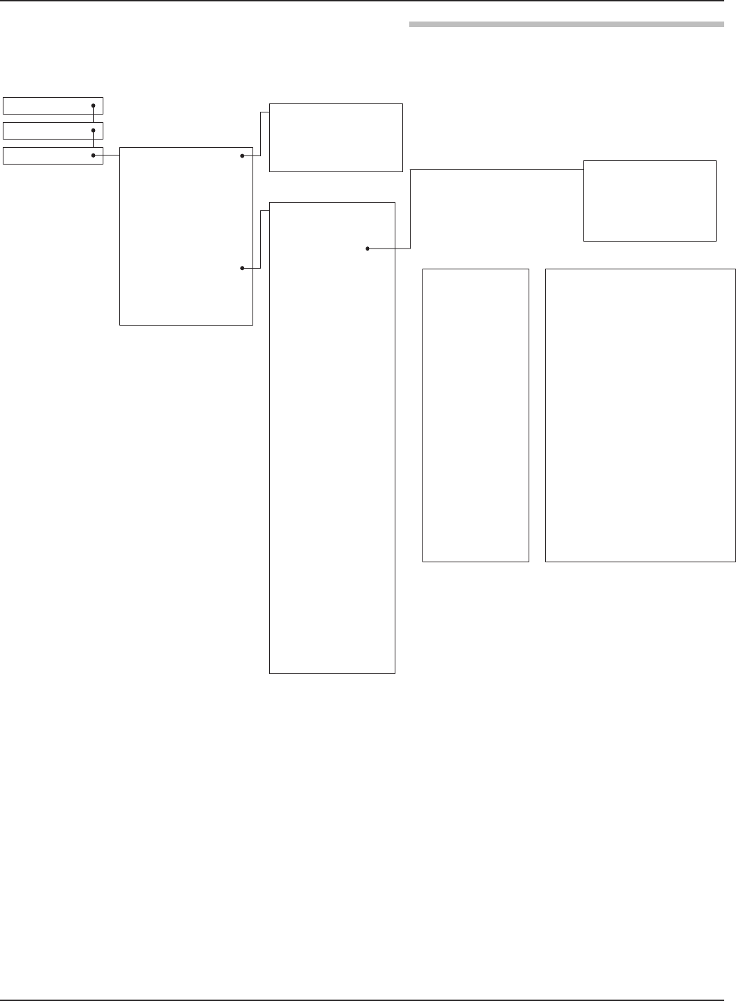
HomeScreen
Main Menu
Device Setup Identity
BasicConfig
Model (read only)
Magnetrol S/N (read only)
Hardware Rev. (read only)
Firmware Rev. (read only)
Long Tag
Measurement Type:
LevelOnly
Flow
SystemUnits
Volume and Level
System Units:
Inches
Feet
Millimeters
Centimeters
Meters
Antenna Model:
RB1-x 1.5" Horn
RB2-x 2" Horn
RB3-x 3" Horn
RB4-x 4" Horn
Antenna Extension:
-0* No nozzle
-1* Nozzle ≤ 4"
-2* Nozzle ≤ 8"
-3* Nozzle ≤ 12"
-4* Nozzle ≤ 24"
-5* Nozzle ≤ 48"
-6* Nozzle ≤ 72"
Rate of Change:
< 5 in/min
5-20 in/min
20-60 in/min
> 60 in/min
Display Config
AdvancedConfig
FactoryConfig
I/O Config
ECHO REJECTION:
View Echo Curve
View Reject Curve
Echo Rejection Type
Standard
Custom
Echo List Mode
Level
Distance
Live Echo List
Rejected Echo List
Reject Curve End
Echo Reject State
Off
Disabled
Enabled
NEW REJECT CURVE
Select Target Echo
New Rej Curve End
Save Reject Curve
Tank Height:
20 inches to 130 feet
(50 cm to 40 meters)
2.6.5 Model R86 Configuration Menu — Device Setup
NOTE: Context-sensitive HELP is available for all menu items. With the menu item highlighted, hold
down the ➪ENTER key for two seconds. Use UP and DOWN for navigation.
➪
➪
28 58-603 Pulsar®Model R86 Radar Transmitter
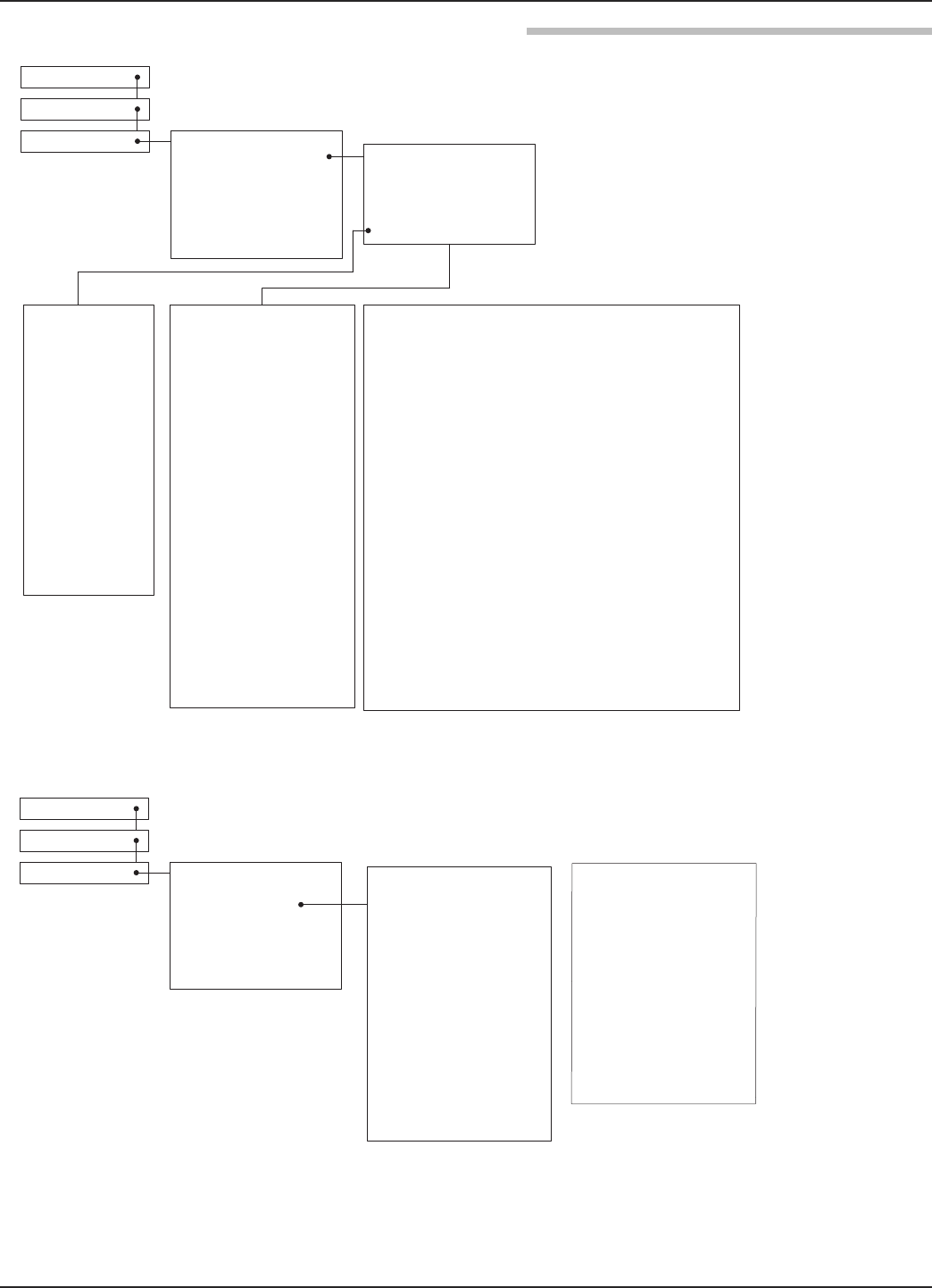
Home Screen
Main Menu
Device Setup Identity
BasicConfig
Display Config
Advanced Config
FactoryConfig
Measurement Type:
LevelOnly
Flow
SYSTEM UNITS
Volume and Level
Dielectric Range:
1.7to3.0
3.0to10
Above 10
Volume Units:
Cubic Feet
Cubic Inches
Gallons
Milliliters
Liters
Vessel Type:
Rectangular
Horizontal/Flat
Horizontal/Elliptical
Horizontal/Spherical
Spherical
Vertical/Flat
Vertical/Elliptical
Vertical/Spherical
Vertical/Conical
Custom Table
VESSEL DIMENSIONS:
(not used with Custom Table)
Width
Length
Sensor Offset
Level Units:
Inches
Feet
Millimeters
Centimeters
Meters
Antenna Mount:
NPT
BSP
Flange
Tank Height:
20 inches to 130 feet
(50 cm to 40 meters)
Stillwell I.D.:
1.6 to 19.7 inches
(40 to 5000 mm)
Turbulance:
None
Light
Medium
Heavy
Foam:
None
Light
Medium
Heavy
Volume Config
I/O Config
Antenna Model:
RB1-x 1.5" Horn
RB2-x 2" Horn
RB3-x 3" Horn
RB4-x 4" Horn
Barrels
Rate of Change:
< 5 in/min
5-20 in/min
20-60 in/min
> 60 in/min
Home Screen
Main Menu
Device Setup Identity
Display Config
Volume Config
I/O Config
CUSTOM TABLE SETUP:
Custom Table Type:
Linear
Spline
Basic Config
Level Input Source:
Keypad
Sensor
CUSTOM TABLE VALUES:
Antenna Extension:
-0* No nozzle
-1* Nozzle ≤ 4"
-2* Nozzle ≤ 8"
-3* Nozzle ≤ 12"
-4* Nozzle ≤ 24"
-5* Nozzle ≤ 48"
-6* Nozzle ≤ 72"
ECHO REJECTION:
View Echo Curve
View Reject Curve
Echo Rejection Type
Standard
Custom
Echo List Mode
Level
Distance
Live Echo List
Rejected Echo List
Reject Curve End
Echo Reject State
Off
Disabled
Enabled
NEW REJECT CURVE
Select Target Echo
New Rej Curve End
Save Reject Curve
2.6.5 Model R86 Configuration Menu — Device Setup
29
58-603 Pulsar®Model R86 Radar Transmitter
Home Screen
Main Menu
Device Setup Identity
Basic Config
I/O Config
Display Config
Advanced Config
Factory Config
Primary Variable (PV)
4 mA Set Pt (LRV):
0 to 130 feet
(0 to 40 meters)
0 to 9999999 gals (Volume)
20 mA Set Pt (URV):
0 to 130 feet
(0 to 30 meters)
0 to 9999999 cf (Volume)
PV Alarm Selection:
High
Low
Hold (Last Output Value)
Damping:
0 to 10 seconds
Language:
English
French
German
Spanish
Russian
Portuguese
Status Symbol:
Hide
View
Long Tag:
Hide
View
PV Bar Graph:
Hide
View
Level:
Hide
View
Volume:
(Volume and Level mode only)
Hide
View
Distance:
Hide
View
PV % Range:
Hide
View
Loop Current:
Hide
View
Echo Strength:
Hide
View
Echo Margin:
Hide
View
Elec Temp:
Hide
View
2.6.5 Model R86 Configuration Menu — Device Setup

30 58-603 Pulsar®Model R86 Radar Transmitter
Home Screen
Main Menu
Device Setup Identity
Basic Config
I/O Config
Display Config
Advanced Config
Factory Config
Sensitivity:
50 to 200
Top Blocking Distance:
-12 to 120 inches
(-30 cm to 3 meters)
Bottom Blocking Distance:
0 to 120 inches
(0 to 3 meters)
SAFETY ZONE SETTINGS
Safety Zone Alarm:
None
3.6 mA
22 mA
Latched 3.6 mA
Latched 22 mA
Safety Zone Height:
(not used when Safety Alarm is
None)
2 inches to 20 feet
(5 cm to 6 meters)
Reset SZ Alarm
(used when Safety Alarm is
Latch 3.6 mA or Latch 22 mA)
ECHO LOSS SETTINGS:
Echo Loss Alarm:
High
Low
Hold (Last Value Output)
Echo Loss Delay:
1 to 1000 seconds
Failure Alarm Delay:
0 to 5 seconds
Level Trim:
-10 to +10 inches
(-25 to +25 cm)
THRESHOLD SETTINGS
Target Selection:
First Echo
Largest Echo
Target Thresh Mode:
Automatic
Fixed Value
Target Thresh Value:
0-99
Base Threshold:
0–99 ESU
TIME VARIABLE GAIN:
TVG Start Value
TVG Start Location
TVG End Value
TVG End Location
# Run Average
Max Surface Velocity
Max Level Jump
Empty State Delay
Compound Peak Logic
Disabled
Enabled
ANALOG OUTPUT:
HART Poll Address:
0 to 63
Loop Current Mode:
Disabled (Fixed)
Enabled (PV)
[Fixed Current Value]
4 to 20 mA
ADJUST ANALOG
OUTPUT:
Adjust 4mA
Adjust 20mA
New User Password:
0 to 59,999
CONFIG CHANGED:
Indicator Mode:
Disabled
Enabled
Reset Config Chngd:
Reset?
No
Yes
Reset Parameters:
No
Yes
2.6.5 Model R86 Configuration Menu — Device Setup
31
58-603 Pulsar®Model R86 Radar Transmitter
Home Screen
Main Menu
Device Setup Identity
Basic Config
I/O Config
Display Config
Advanced Config
Factory Config NAP
Factory Reset
FACTORY CALIBRATION
(Factory password required)
Elec Temp Offset
Conversion Factor
Scale Offset
Window
Fiducial Gain: 0-255 (read only)
Fiducial Strength
Initial Gain
TVG Divisor
2.6.5 Model R86 Configuration Menu — Device Setup
32 58-603 Pulsar®Model R86 Radar Transmitter
2.7 Configuration Using HART®
A HART (Highway Addressable Remote Transducer)
remote unit, such as a HART communicator, can be used to
provide a communication link to the PULSAR Model R86
transmitter. When connected to the control loop, the same
system measurement readings shown on the transmitter are
also shown on the communicator. The communicator can
also be used to configure the transmitter.
The HART communicator may need to be updated to
include the PULSAR Model R86 software (Device
Descriptions). Refer to your HART Communicator Manual
for update instructions.
One can also access configuration parameters using
PACTware and the Model R86 DTM, or using the AMS
with EDDL.
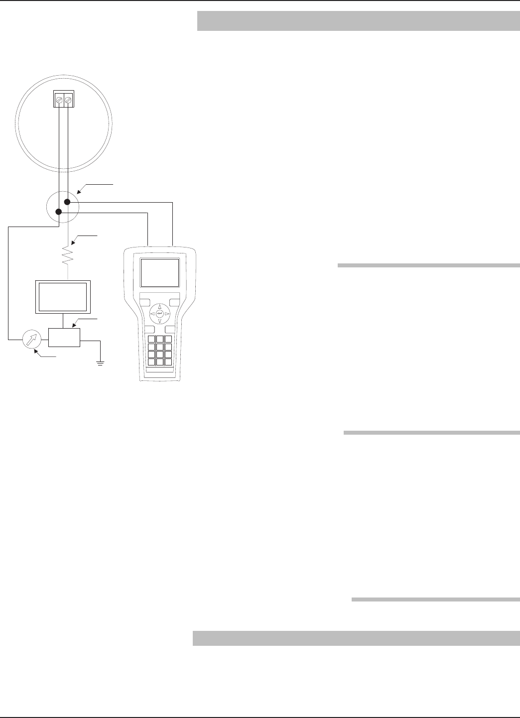
2.7.1 Connections
A HART communicator can be operated from a remote
location by connecting it to a remote junction or by con-
necting it directly to the terminal block in the electronics
housing of the PULSAR Model R86 transmitter.
HART uses the Bell 202 frequency shift key technique of
high-frequency digital signals. It operates on the 4–20 mA
loop and requires 250 Ωload resistance. A typical connec-
tion between a communicator and the PULSAR Model R86
transmitter is illustrated.
2.7.2 Display Menu
A typical communicator display is an 8-line by 21-character
LCD. When connected, the top line of each menu displays
the model (Model R86) and its tag number or address. For
detailed operating information, refer to the instruction
manual provided with the HART communicator.
The PULSAR Model R86 transmitter online menu trees are
shown in the following illustration. Open the menu by
pressing the alphanumeric key 4, Device Setup, to display
the second-level menu.
2.7.3 HART Revision Table
2.7.3.1 Model R86
HART Version HCF Release Date Compatible with R86 Software
Dev V1 DD1 April 2017 Version 1.0a and later
+
-
Junction
RL > 250 Ω
Control
Room
Display
Power
Supply
Current
Meter
33
58-603 Pulsar® Model R86 Radar Transmitter
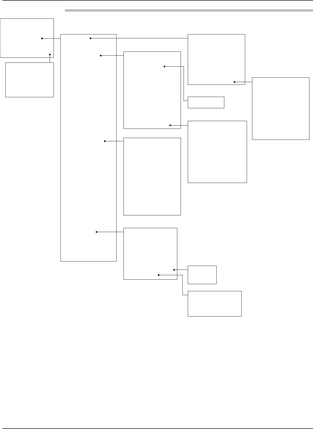
2.7.4 HART Menu
1 Echo Graph
2 Curve 1
3 Curve 2
4 Refresh Echo List
5 Echo Reject State
6 Echo List Type
7 Echo List Mode
8 Saved Reject Distance
9 Saved Reject Location
10 New Rejection Curve
11 Echo List grid
1 PV
2 PV Loop Current
3 PV % Range
4 Device Setup
5 Setup Wizard
6 Diagnostics
7 Measured Values
1 Level
2 Volume
3 Distance
4 Echo Strength
5 Echo Margin
6 Temperature
1 Identity
2 Basic Config
3 Volume Config
4 I/O Config
5 Local Display Config
6 Advanced Config
7 Factory Config
1 Enter Password
2 PV is
3 PV LRV
4 PV URV
5 PV AO Alarm Type
6 Damping
7 I/O Config Diagram
8 Variable Selection
9 Set Points
1 Manufacturer
2 Model
3 Magnetrol S/N
4 Hardware Rev.
5 Firmware Rev.
6 Cfg chng count
7 Dev id
8 Universal Rev
9 Fld Dev Rev
10 Software Rev
11 Num Req Preams
1 Enter Password
2 Vessel Type
3 Length
4 Width
5 Radius
6 Ellipse Depth
7 Conical Height
8 Sensor Offset
9 Table Type
10 Level Source
11 Sensor Input
12 Vessel Diagrams
13 Table Length
14 Custom Table
1 SV is
2 TV is
3 4V is
1 Lvl 4mA Set Point
2 Lvl 20mA Set Point
3 Vol 4mA Set Point
4 Vol 20mA Set Point
1 Enter Password
2 Tag
3 Long Tag
4 Descriptor
5 Final asmbly num
6 Date
7 Message
8 Date/Time/Initials
9 Factory Identity
1 Enter Password
2 Measurement Type
3 System Units
4 Antenna Model
5 Antenna Extension
6 Antenna Mount
7 Basic Config Diagram
8 Tank Height
9 Stillwell I.D.
10 Dielectric Range
11 Turbulance
12 Foam
13 Rate of Change
14 Echo Rejection
1 Level Units
2 Volume Units
34 58-603 Pulsar® Model R86 Radar Transmitter
2.7.4 HART Menu (continued)
1 Safety Zone Alarm
2 Safety Zone Height
3 Reset SZ Alarm
1 PV
2 PV Loop Current
3 PV % Range
4 Device Setup
5 Setup Wizard
6 Diagnostics
7 Measured Values
1 Level
2 Volume
3 Distance
4 Echo Strength
5 Echo Margin
6 Temperature
1 Identity
2 Basic Config
3 Volume Config
4 I/O Config
5 Local Display Config
6 Advanced Config
7 Factory Config 1 Enter Password
2 Fiducial Adjustment
3 NAPValue
4 Factory Reset
5 Factory Param 1
6 Factory Param 2
7 Factory Param 3
8 Factory Param 4
9 Factory Calib
1 Level
2 Distance
3 Volume
4 Echo Strength
5 Signal Margin
6 PV % Range
7 Loop Current
8 Elec Temp
1 Enter Password
2 Language
3 Status Symbol
4 Long Tag
5 PV Bar Graph
6 Measured Values
1 Enter Password
2 Sensitivity
3 Top Blocking Distance
4 Bottom Blocking Distance
5 Safety Zone Settings
6 Echo Loss Settings
7 Failure Alarm Delay
8 Adv Config Diagram
9 Level Trim
10 Threshold Settings
11 Time Variable Gain
12 # Run Average Depth
13 Max Surface Velocity
14 Max Distance Jump
15 Empty State Delay
16 Analog Output
17 New User Password
18 Reset Parameters
1 Echo Loss Alarm
2 Echo Loss Delay
1 Target Selection
2 Target Thresh Mode
3 Target Thresh Value
4 Base Threshold
1 TVG Start Value
2 TVG End Value
3 TVG Start Location
1 Poll Address
2 Loop Current Mode
3 Fixed Loop Current
4 Adjust Analog Output
5 4 mA Trim Value
6 20 mA Trim Value
7 Fdbk 4 mA Trim Value
8 Fdbk 20 mA Trim Value
1 Fiducial Gain
2 Fiducial Strength
3 Window
4 Fiducial Ticks
5 TVG Start Location
1 Conversion Factor
2 Scale Offset
3 Elec Temp Offset
4 TVG Divisor
35
58-603 Pulsar®Model R86 Radar Transmitter
3.0 Reference Information
This section presents an overview of the operation of the
PULSAR Model R86 Radar Level Transmitter, information
on troubleshooting, common problems, listings of agency
approvals, lists of replacement and recommended spare
parts, and detailed physical, functional and performance
specifications.
3.1 Description
The PULSAR Model R86 is a two-wire, 24 VDC, level
transmitter based on the concept of pulse burst radar. The
electronics are housed in an ergonomic housing comprised
of two tandem compartments angled at a 20-degree angle
for ease of wiring and calibration. These two compartments
connect via a watertight feed-through.
3.2 Theory of Operation
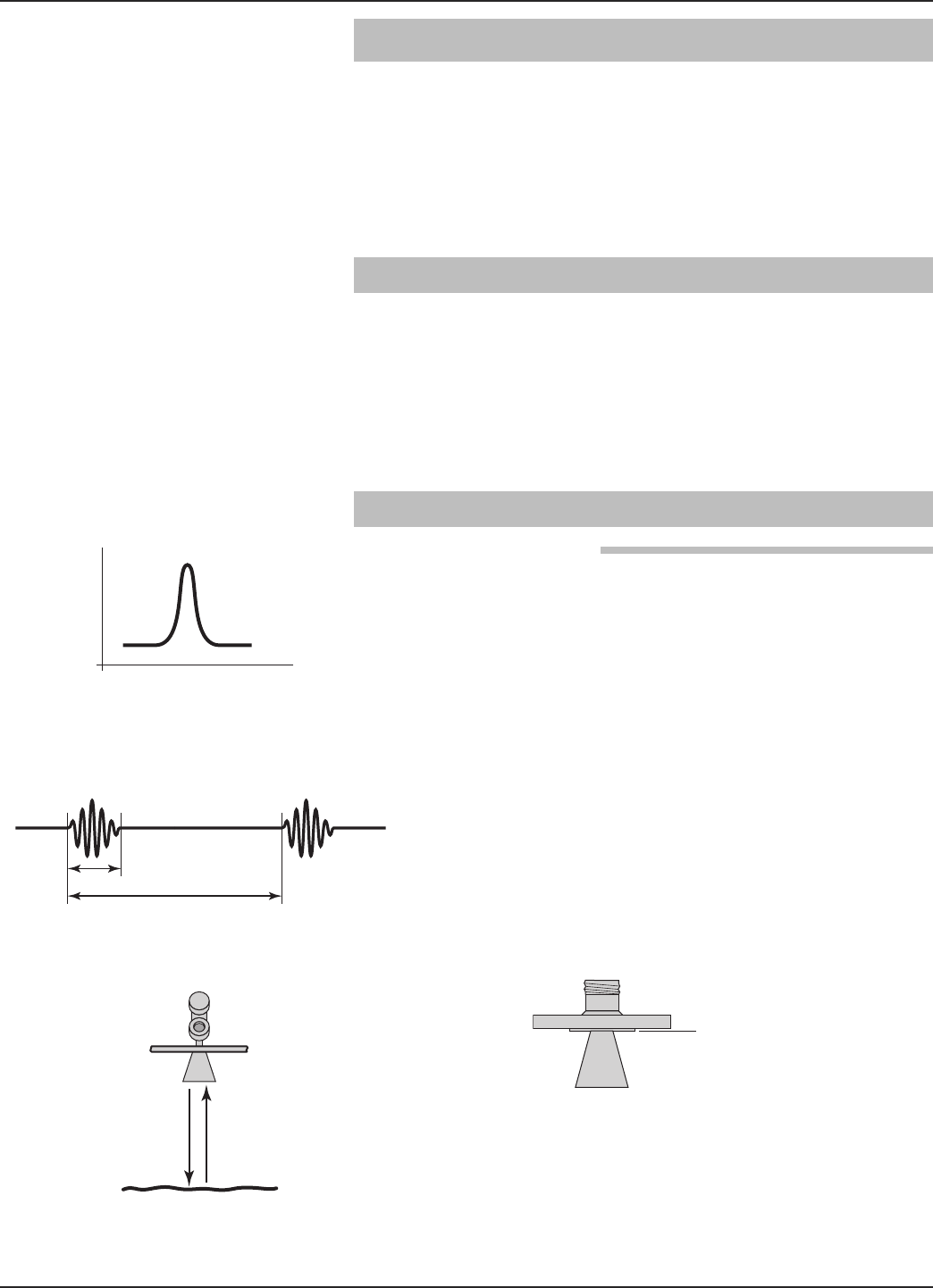
3.2.1 Pulse Burst Radar
PULSAR Model R86 is a top-mounted, downward-looking
pulse burst radar operating at 26 GHz. Unlike true pulse
devices (GWR, for example) that transmit a single, sharp
(fast rise-time) waveform of wide-band energy, PULSAR
Model R86 emits short bursts of 26 GHz energy and meas-
ures the transit time of the signal reflected off the liquid
surface. Distance is calculated utilizing the equation:
Distance = C (Speed of light) ×Transit time/2, then devel-
oping the Level value by factoring in application-specific
configuration. The exact reference point for distance and
level calculations is the Sensor Reference Point—bottom of
an NPT thread, top of a BSP thread or face of a flange.
1 ns
500 ns
Distance = c × (time ÷ 2)
ANSI or DIN
Welded Flange
Sensor Reference Point
Pulse
Pulse Burst
36 58-603 Pulsar®Model R86 Radar Transmitter
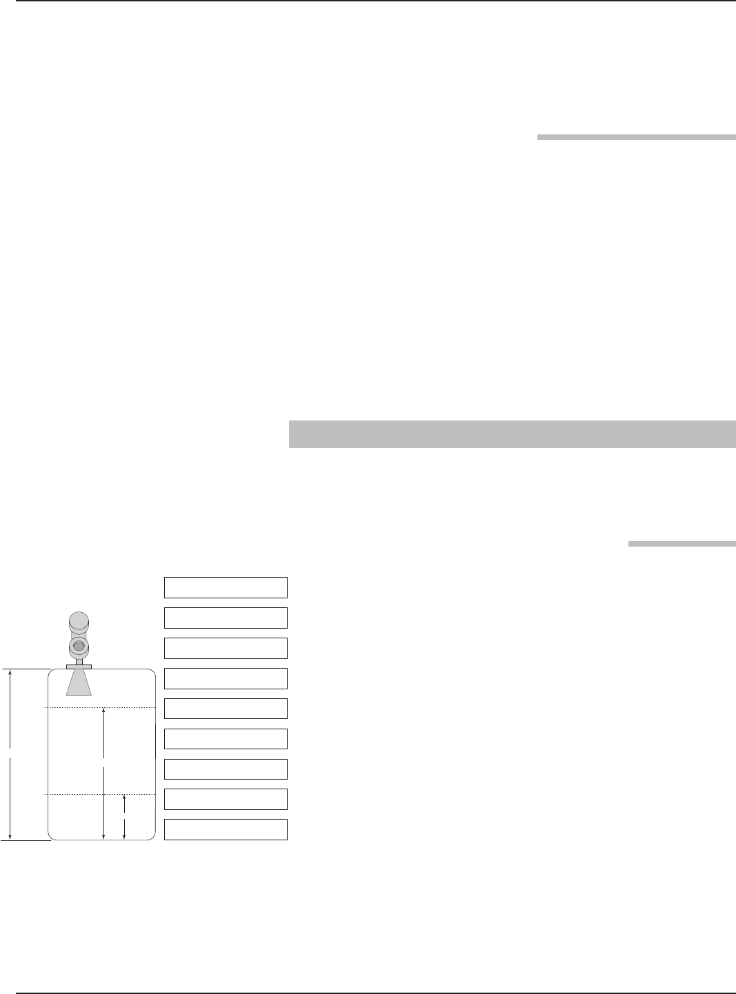
60"
20 mA
4 mA
24"
Level Units = inches
Antenna Model = RB2
Tank Height = 82 in
Antenna Mount = Flange
Dielectric Range =
Above 10
4 mA = 24 in
20 mA = 60 in
82"
Bottom Blocking
Distance = 0 in
Antenna Extension = 0
Example 1
The exact level measurement is extracted from false target
reflections and other background noise via the use of
sophisticated signal processing. The new PULSAR Model
R86 circuitry is extremely energy efficient so no duty cycling
is necessary to accomplish effective measurement.
3.2.2 Equivalent Time Sampling
ETS, or Equivalent Time Sampling, is used to measure the
high speed, low power EM (electromagnetic) energy. ETS is
a critical key in the application of Radar to vessel level
measurement technology. The high speed electromagnetic
energy (1000 ft/µs) is difficult to measure over short dis-
tances and at the resolution required in the process industry.
ETS captures the EM signals in real time (nanoseconds) and
reconstructs them in equivalent time (milliseconds), which
is much easier to measure with today’s technology.
ETS is accomplished by scanning the tank to collect thou-
sands of samples. Approximately three scans are taken per
second; each scan gathers more than 50,000 samples.
3.3 Configuration Information
This section is intended to offer additional configuration-
related details with respect to some of the parameters shown
in the Menu in Section 2.6.
3.3.1 Bottom Blocking Distance Description
The parameter referred to as Bottom Blocking Distance in
the PULSAR Model R86 DEVICE SETUP/ADVANCED
CONFIG menu is defined as the distance from the bottom
of the tank to the lowest valid level reading.
NOTE: The level reading will never be lower than the Bottom Blocking
Distance or higher than the Top Blocking Distance.
The PULSAR Model R86 transmitter is shipped from the
factory with Bottom Blocking Distance set to 0. With this
configuration, level measurements are referenced from the
bottom of the tank. See Example 1.
Example 1 (Bottom Blocking Distance = 0 as shipped
from factory):
Application calls for a Model RB2 antenna in an 82-inch
tank with a flanged process connection. The process
medium is water.
The user wants the 4 mA Set Point (LRV) at 24 inches
and the 20 mA Set Point (URV) at 60 inches as
referenced from the bottom of the tank.
37
58-603 Pulsar®Model R86 Radar Transmitter
Example 2 (Bottom Blocking Distance = 10 inches):
Application calls for a Model RB4 antenna in an 100-
inch tank with a flanged process connection.
The user wants the 4 mA Set Point (LRV) at 24 inches
and the 20 mA Set Point (URV) at 60 inches as
referenced from the Blocking Distance.
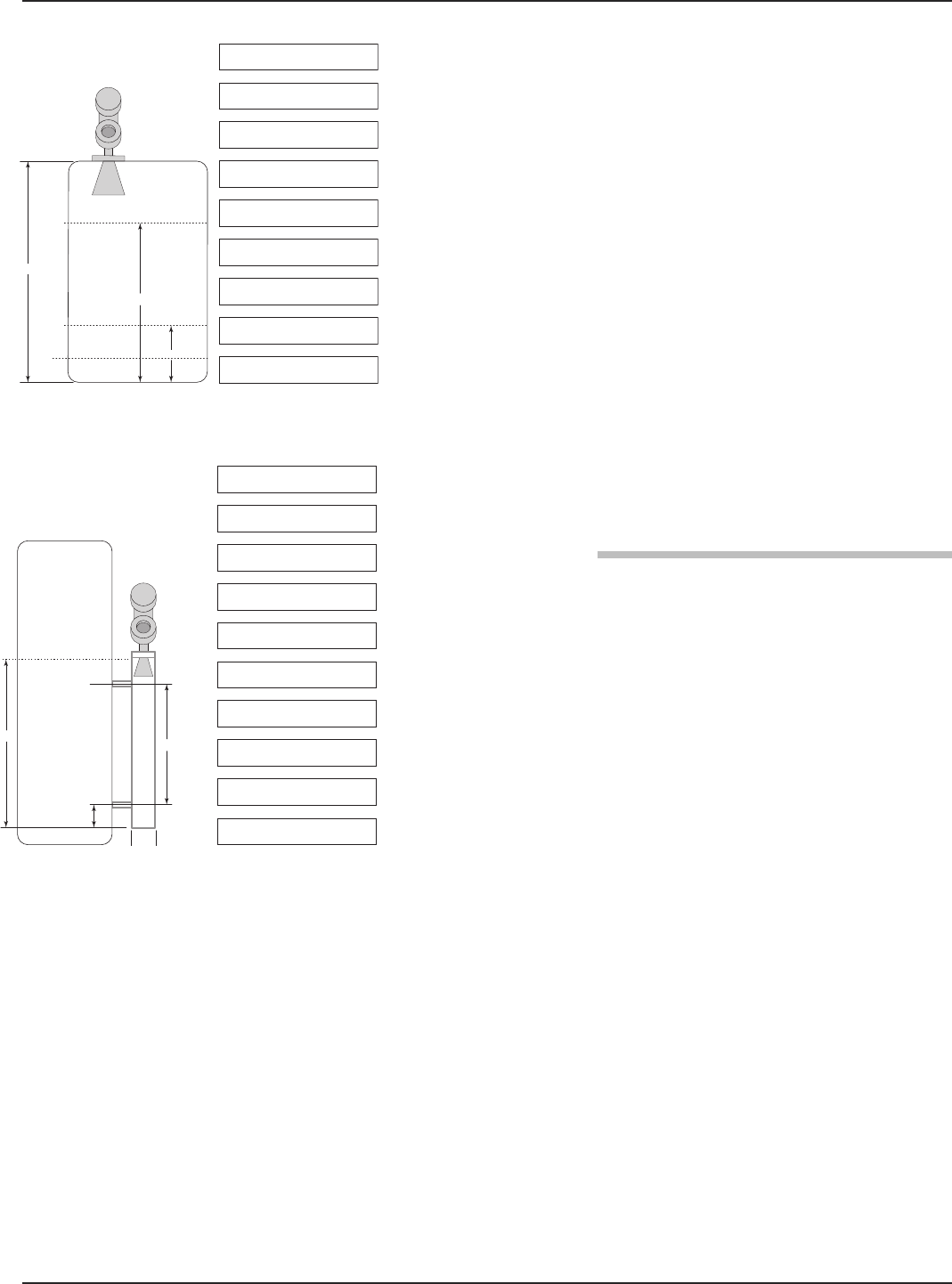
When the PULSAR Model R86 transmitter is mounted in a
stillwell, it is usually desirable to configure the unit with the
4 mA Set Point (LRV) at the lower process connection and
the 20 mA Set Point (URV) at the upper process connec-
tion. The measuring range then becomes the center-to-cen-
ter dimension.
Example 3:
Application calls for a Model RB3 flanged antenna meas-
uring water in a 3-inch chamber. The user wants the
4 mA point to be 6 inches at the bottom process connec-
tion and the 20 mA point to be 30 inches at the top
process connection.
3.3.2 Reset Function
A parameter labeled “Reset Parameter” is located at the end
of the DEVICE SETUP/ADVANCED CONFIG menu.
In the event a user gets confused during configuration or
advanced troubleshooting, this parameter gives the user the
ability to reset the Model R86 transmitter configuration.
Unique to the Model R86 transmitter is the ability for
MAGNETROL to fully “pre-configure” devices to customer
requests. For that reason, the Reset function will return the
device back to the state at which it left the factory.
It is recommended that MAGNETROL Technical Support
be contacted as the Advanced User password will be
required for this reset.
10"
60"
20 mA
4 mA
24"
Dielectric Range =
Above 10
4 mA = 14 in
20 mA = 50 in
100"
Bottom Blocking
Distance = 10 in
Antenna Model = RB4
Antenna Extension = 0
Antenna Mount = Flange
Level Units = inches
Tank Height = 82 in
Example 2
6"
30"
4 mA
20 mA
Level Units = inches
Antenna Model = RB3
Tank Height = 48 in
Dielectric Range =
Above 10
4 mA = 0 in
20 mA = 30 in
Stillwell ID = 3 in
3"
48"
Antenna Mount = Flange
Antenna Extension = 0
Bottom Blocking
Distance = 6.0 in
Example 3

38 58-603 Pulsar®Model R86 Radar Transmitter
3.3.3 Echo Rejection
Since all Non-Contact radar transmitters are
application/installation dependent, Echo Rejection
(ignoring false targets) may be necessary.
The Model R86 transmitter Echo Rejection feature is
located in the DEVICE SETUP/BASIC CONFIG menu,
and requires the User Password to activate. It is highly
recommended that this feature be used with the waveform
capture capability of the Model R86 DTM and PACTware™.
Refer to Section 4.0 “Advanced Configuration/
Troubleshooting Techniques” or contact MAGNETROL
Technical Support for additional instructions.
3.3.4 Volumetric Capability
Selecting Measurement Type = Volume and Level allows the
Model R86 transmitter to measure volume as the Primary
Measured Value.
3.3.4.1 Configuration using built-in Vessel Types
The following table provides an explanation of each of the
System Configuration parameters required for volume
applications that use one of the nine Vessel Types.
Configuration Parameter Explanation
System Units A selection of Gallons, Barrels, Milliliters, Liters, Cubic Feet, or Cubic Inches, is provided.
(Factory default is Cubic Feet)
Vessel Type
Select either Vertical/Flat (factory default Vessel Type), Vertical/Elliptical, Vertical/Spherical,
Vertical/Conical, Rectangular, Horizontal/Flat, Horizontal/Elliptical, Horizontal/Spherical,
Spherical, or Custom Table.
Note: Vessel Dims is the next screen only if a specific Vessel Type was selected. If Custom Table
was selected. Refer to page 48 to select the Cust Table Type and Cust Table Vals.
Vessel Dims See the vessel drawings on the following page for relevant measuring areas.
Radius Used for all Vessel Types with the exception of Rectangular.
Ellipse Depth Used for Horizontal and Vertical/Elliptical vessels.
Conical Height Used for Vertical/Conical vessels.
Width Used for Rectangular vessels.
Length Used for Rectangular and Horizontal vessels.
MEASUREMENT TYPE = LEVEL & VOLUME
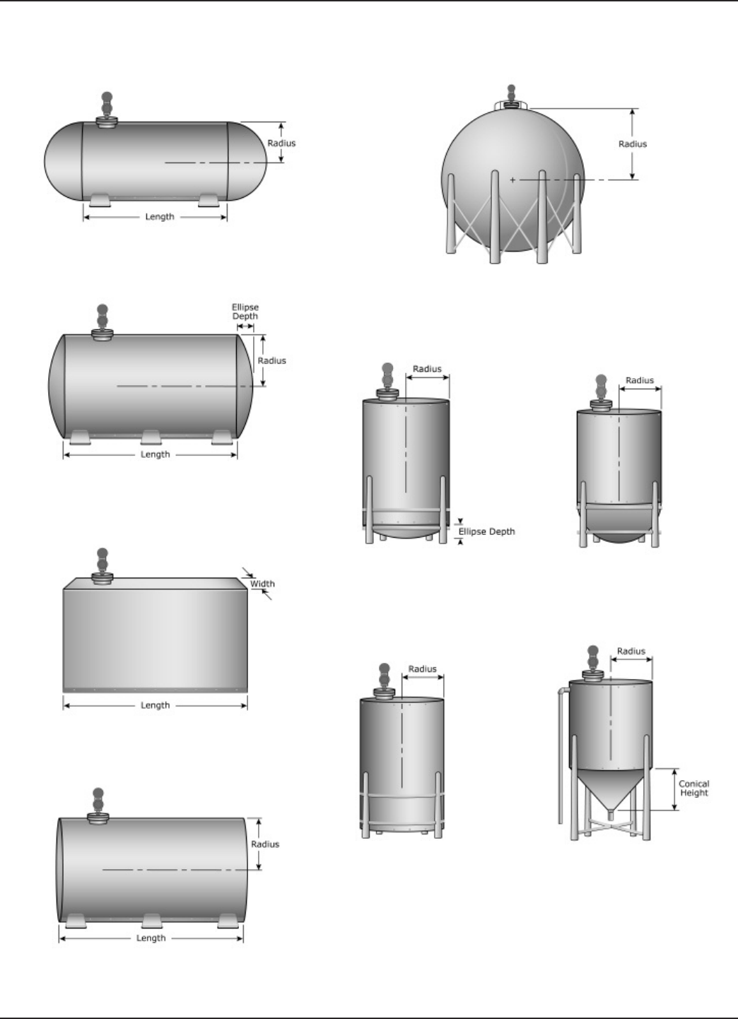
39
58-603 Pulsar®Model R86 Radar Transmitter
SPHERICAL
HORIZONTAL/SPHERICAL
Vessel Types
VERTICAL/FLAT VERTICAL/CONICAL
HORIZONTAL/FLAT
RECTANGULAR
HORIZONTAL/ELLIPTICAL
VERTICAL/ELLIPTICAL VERTICAL/SPHERICAL
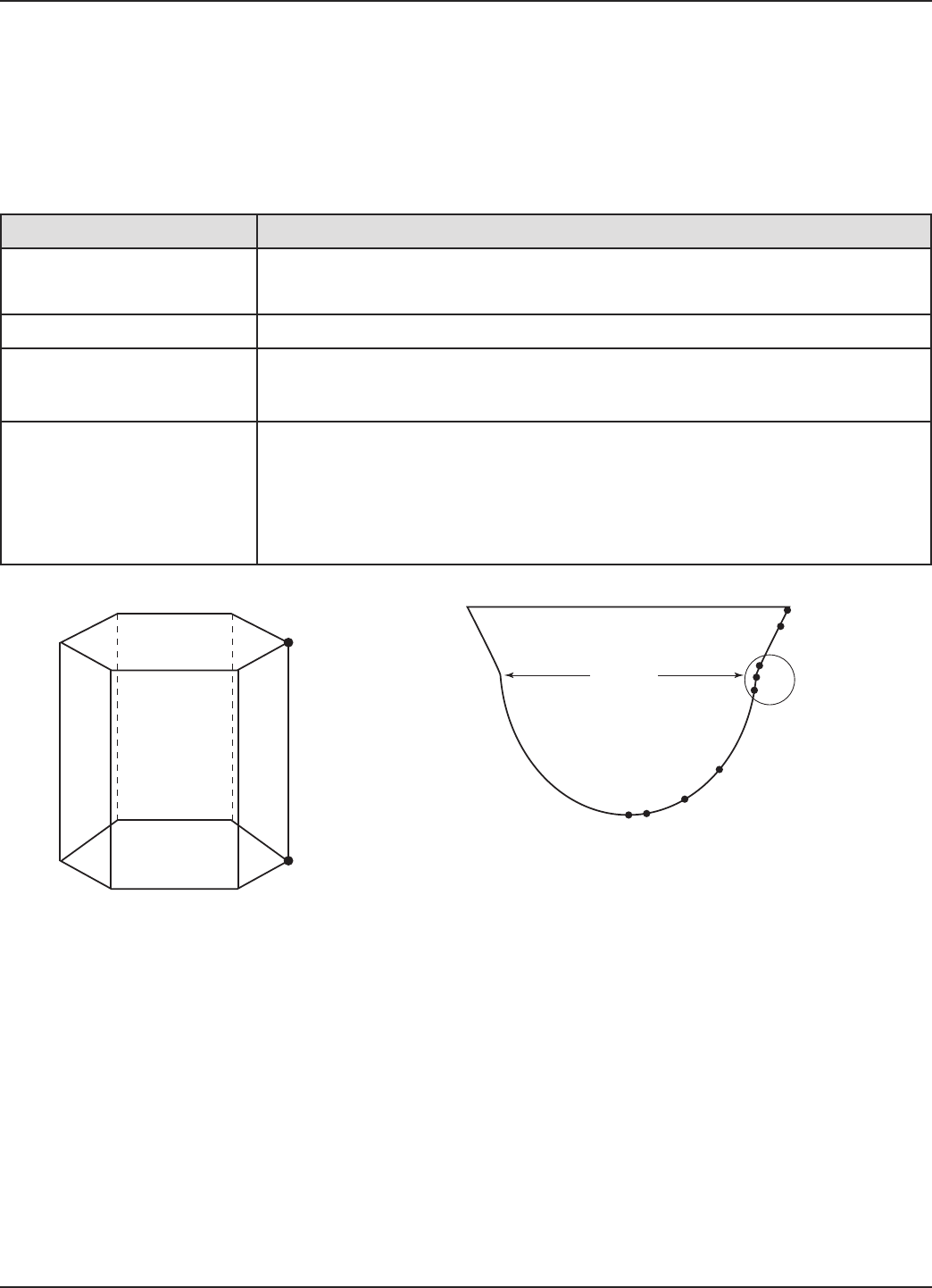
40 58-603 Pulsar®Model R86 Radar Transmitter
3.3.4.2 Configuration using Custom Table
If none of the nine Vessel Types shown can be used, a
Custom Table can be created. A maximum of 30 points can
be used to establish the level to volume relationship. The
following table provides an explanation of each of the
System Configuration parameters for volume applications
where a Custom Table is needed.
Configuration Parameter Explanation (Custom Volumetric Table)
Volume Units A selection of Gallons, Barrels, Milliliters, Liters,Cubic Feet, or Cubic Inches,
is provided.
Vessel Type Select Custom Table if none of the nine Vessel Types can be used.
Cust Table Type
The Custom Table points can be a Linear (straight line between adjacent points) or
Spline (can be a curved line between points) relationship. See drawing below for
more information.
Cust Table Vals
A maximum of 30 points can be used in building the Custom Table. Each pair of
values will have a level (height) in the units chosen in the Level Units screen, and
the associated volume for that level point. The values must be monotonic, i.e.,
each pair of values must be greater than the previous level/volume pair. The last
pair of values should have the highest level value and volume value associated
with the level in the vessel.
LINEAR SPLINE
P2
P1
P1 P2
P3
P4
P5
P6
P7
P8
P9
Transition
point
Use where walls are not perpendicular to base.
Concentrate at least two points at beginning (P1) and end (P9);
and three points at either side of transition points.
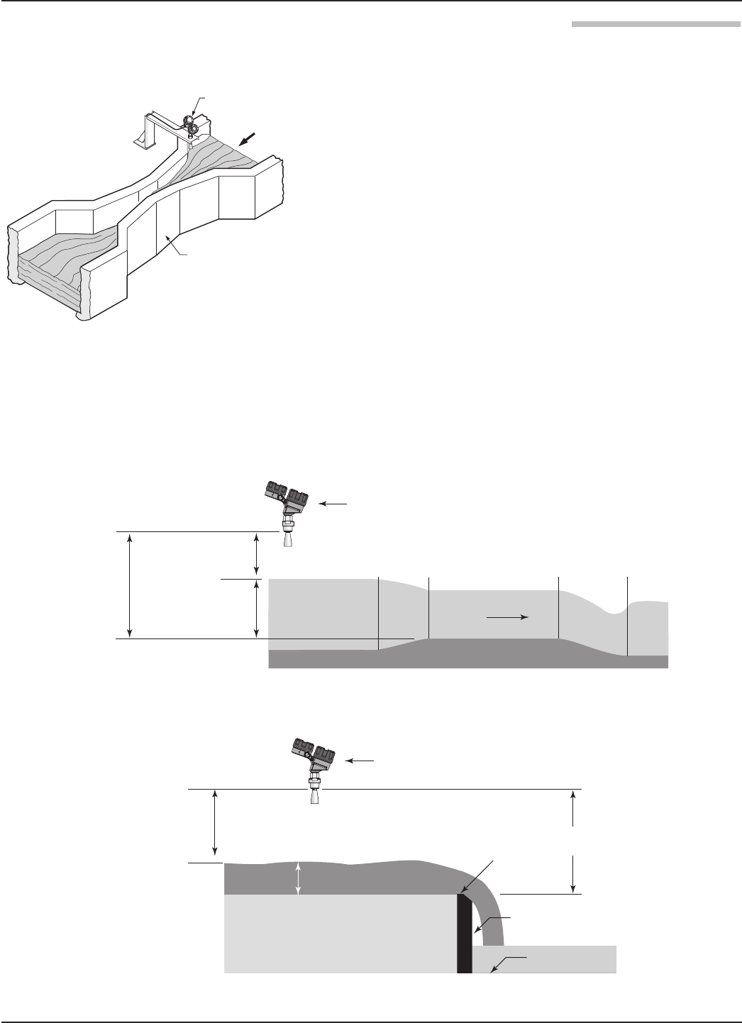
41
58-603 Pulsar®Model R86 Radar Transmitter
3.3.5 Open Channel Flow Capability
Selecting Measurement Type = Flow allows the PULSAR
Model R86 transmitter to measure flow as the Primary
Measured Value.
Open channel flow is performed by using the Model R86 to
measure the Head in a hydraulic structure. The hydraulic
structure is the primary measuring element, of which the
two most common types are weirs and flumes.
Since the primary element has a defined shape and dimen-
sions, the rate of flow through the flume or over the weir is
related to the Head at a specified measurement location.
The Model R86 is the secondary measuring device, which
measures the Head of the liquid in the flume or weir. Open
channel flow equations stored in the transmitter firmware
convert the measured Head into units of flow
(volume/time).
NOTE: Proper positioning of the Model R86 should be per the recom-
mendation of the flume or weir manufacturer.
Model R86
Flow
Parshall
Flume
Open Channel Flow Measurement
Parshall Flume
Model
R86
Flow
Water Surface
Throat Section
Head
Blocking Distance
12" (300 mm)
Reference
Distance
Head
Crest
Channel Floor
Blocking
Distance
12" (300 mm)
Weir Plate
Water Surface
Reference
Distance
Model
R86
Flume (side view)
Weir (side view)

42 58-603 Pulsar®Model R86 Radar Transmitter
3.3.5.1 Configuration using Flume/Weir Equations
The following table provides an explanation of each of the
System Configuration parameters required for open channel
flow applications using one of the Flow Elements that are
stored in the firmware.
Configuration Parameter Explanation
Flow Units
A selection of Gallons/Minute (factory default Flow Unit), Gallons/Hour, Mil
Gallons/Day, Liters/Second, Liters/Minute, Liters/Hour, Cubic Meter/Hour,
Cubic Ft/Second, Cubic Ft/Minute, and Cubic Ft/Hour are provided.
Flow Element
Select one of the following primary Flow Elements that are stored in the firmware:
Parshall flume sizes of 1", 2", 3", 6", 9", 12", 18", 24", 36", 48", 60", 72", 96",
120" and 144". Palmer-Bwls (Palmer-Bowlus) flume sizes of 4", 6", 8", 10", 12",
15", 18", 21", 24", 27" and 30". V-notch weir sizes of 22.5O, 30O, 45O, 60O, 90Oand
120O. Rect with Ends (Rectangular Weir with End Contractions), Rect w/o Ends
(Rectangular Weir without End Contractions), and Cipoletti weir. Custom Table (see
page 44 can be selected if none of the stored Flow Elements can be used. The
table can be built with a maximum of 30 points. The Model R86 also has the
capability of using a Generic Equation (see page 43) for flow calculation.
Weir Crest Length
The Weir Crest Length screen only appears when the chosen Flow Element is
Cipoletti or one of the Rectangular weirs. Input this length in the user-selected
level units.
Flume Channel Width Allows for entry of the width of the palmer bowlus flume.
V-Notch Weir Angle Only appears when flow element is V-Notch weir. It allows for the entry of angle of
the V-Notch weir.
Reference Dist
The Reference Distance is measured from the sensor reference point to the point
of zero flow in the weir or flume. This must be measured very accurately in the
user-selected level units.
Maximum Head
Maximum Head is the highest liquid level (Head) value in the flume or weir before
the flow equation is no longer valid. The Maximum Head is expressed in the user-
selected Level Units. The Model R86 will default to the largest Maximum Head value
that is allowed for any given flume or weir. The Maximum Head value can be revised
depending on the value of the Reference Distance, or for end user preference.
Maximum Flow Maximum Flow is a read-only value that represents the flow value corresponding
to the Maximum Head value for the flume or weir.
Low Flow Cutoff
The Low Flow Cutoff (in user-selected level units) will force the calculated flow
value to zero whenever the Head is below this point. This parameter will have a
default and minimum value of zero.

43
58-603 Pulsar®Model R86 Radar Transmitter
3.3.5.2 Configuration using Generic Equation
The following table provides an explanation of each of the
System Configuration parameters for Open channel flow
applications using the Generic Equation.
Configuration Parameter Explanation (Open Channel Flow — using the Generic Equation)
Flow Units
A selection of Gallons/Minute (factory default Flow Unit), Gallons/Hour,
Mil Gallons/Day, Liters/Second, Liters/Minute, Liters/Hour, Cubic Meter/Hour,
Cubic Ft/Second, Cubic Ft/Minute, and Cubic Ft/Hour are provided.
Flow Element
Select one of the following primary Flow Elements that are stored in the firmware:
Parshall flume sizes of 1", 2", 3", 6", 9", 12", 18", 24", 36", 48", 60", 72", 96",
120" and 144". Palmer-Bwls (Palmer-Bowlus) flume sizes of 4", 6", 8", 10", 12",
15", 18", 21", 24", 27" and 30". V-notch weir sizes of 22.5O, 30O, 45O, 60O, 90Oand
120O. Rect with Ends (Rectangular Weir with End Contractions), Rect w/o Ends
(Rectangular Weir without End Contractions), and Cipoletti weir. Custom Table (see
page 44 can be selected if none of the stored Flow Elements can be used. The
table can be built with a maximum of 30 points. The Model R86 also has the
capability of using a Generic Equation (see below) for flow calculation.
Generic Eqn Factors
Generic Equation is a discharge flow equation in the form of Q = K(L-CH)Hn, where
Q = flow (Cu Ft/Second), H = Head (Feet), K = a constant, and L, C and n are user
input factors that depend on which Flow Element is being used. Make sure the flow
equation is in the form of Q = K(L-CH)Hn, and proceed to enter the values of K,L,C,H
and n. See example below.
NOTE: The Generic Equation parameters must be entered in Cu Ft/Second
units. The resultant flow is converted by the Model R86 into whatever Flow Units
are selected above. See example below.
Reference Dist
The Reference Distance is measured from the sensor reference point to the point
of zero flow in the weir or flume. This must be measured very accurately in the
user-selected level units.
Maximum Head
Maximum Head is the highest liquid level (Head) value in the flume or weir before
the flow equation is no longer valid. The Maximum Head is expressed in the user-
selected level units. The Model R86 will default to the largest Maximum Head value
that is allowed for any given flume or weir. The Maximum Head value can be revised
depending on the value of the Reference Distance, or for end user preference.
Maximum Flow Maximum Flow is a read-only value that represents the flow value corresponding
to the Maximum Head value for the flume or weir.
Low Flow Cutoff
The Low Flow Cutoff (in user-selected level units) will force the calculated flow
value to zero whenever the Head is below this point. This parameter will have a
default and minimum value of zero.
Using the factors above the equation becomes:
Q = 3.33 (8-0.2H) H1.5
The discharge flow value for a Head value of three feet
becomes 128.04 Cubic Ft/Second. If GPM was selected for
the Flow Units, the ModelR86 Measured Values screen would
display this value converted to 57,490 GPM.
Generic Equation Example (using equation for an 8' rectangular weir w/ end contractions)
Q = Cubic Ft/Second flow rate L = 8' (weir crest length in feet) H = Head value
K = 3.33 for Cubic Ft/Second units C = 0.2 (constant) n = 1.5 as an exponent
Q = K(L-CH)Hn

44 58-603 Pulsar®Model R86 Radar Transmitter
3.3.5.3 Configuration using Custom Table
The following table provides an explanation of each of the
System Configuration parameters for open channel flow
applications using the Custom Table.
SPLINE OR LINEAR
SPLINE
P1
P2
P3
P4
P5
Concentrate points along curve
P2
P3
P7
P10
Transition
point
P1
Concentrate points as follows:
A. At least two points at beginning (P1 and P2);
B. At least two points at end (P9 and P10);
C. Three points at approximate average flow rate (for
example, P3, P4, P5); and at transition point (P7)
and points on either side (P6, P8).
P5
P4
P6
P8
P9
Average flow rate
Configuration Parameter
Explanation (Open Channel Flow — Custom Table)
Flow Units
A selection of Gallons/Minute (factory default Flow Unit), Gallons/Hour,
Mil Gallons/Day, Liters/Second, Liters/Minute, Liters/Hour, Cubic Meters/Hour,
Cubic Ft/Second, Cubic Ft/Minute, and Cubic Ft/Hour are provided.
Flow Element
Select one of the following primary Flow Elements that are stored in the firmware:
Parshall flume sizes of 1", 2", 3", 6", 9", 12", 18", 24", 36", 48", 60", 72", 96",
120" and 144". Palmer-Bwls (Palmer-Bowlus) flume sizes of 4", 6", 8", 10", 12",
15", 18", 21", 24", 27" and 30". V-notch weir sizes of 22.5O, 30O, 45O, 60O, 90Oand
120O. Rect with Ends (Rectangular Weir with End Contractions), Rect w/o Ends
(Rectangular Weir without End Contractions), and Cipoletti weir. Custom Table
(see page xx can be selected if none of the stored Flow Elements can be used.
The table can be built with a maximum of 30 points. The Model R86 also has the
capability of using a Generic Equation (see page 44) for flow calculation.
Custom Table
The Custom Table points can be a Linear (straight line between adjacent points) or
Spline (can be a curved line between points) relationship. Refer to the drawing
above for more information.
Cust Table Vals
A maximum of 30 points can be used in building the Custom Table. Each pair of val-
ues will have a Head (height) in the units chosen in the Level Units screen, and the
associated flow for that Head value. The values must be monotonic, i.e., each pair
of values must be greater than the previous Head/flow pair. The last pair of values
should have the highest Head value (usually the Maximum Head value) and the flow
associated with that Head value.
Reference Dist
The Reference Distance is measured from the sensor reference point to the point
of zero flow in the weir or flume. This must be measured very accurately in the
user-selected level units.
Maximum Head
Maximum Head is the highest liquid level (Head) value in the flume or weir before
the flow equation is no longer valid. The Maximum Head is expressed in the user-
selected Level Units. The Model R86 will default to the largest Maximum Head value
that is allowed for any given flume or weir. The Maximum Head value can be revised
depending on the value of the Reference Distance, or for end user preference.
Maximum Flow Maximum Flow is a read-only value that represents the flow value corresponding
to the Maximum Head value for the flume or weir.
Low Flow Cutoff
The Low Flow Cutoff (in user-selected level units) will force the calculated flow
value to zero whenever the Head is below this point. This parameter will have a
default and minimum value of zero.
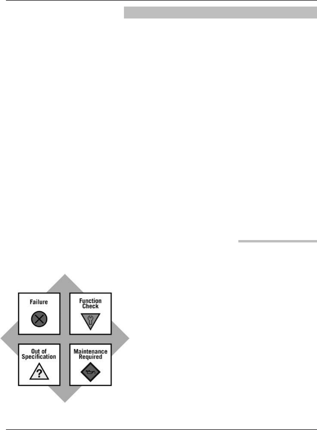
45
58-603 Pulsar®Model R86 Radar Transmitter
3.4 Troubleshooting and Diagnostics
The PULSAR Model R86 transmitter is designed and engi-
neered for trouble-free operation over a wide range of oper-
ating conditions. The transmitter continuously runs a series
of internal self-tests and displays helpful messages on the
large graphic liquid crystal display (LCD) when attention is
required.
The combination of these internal tests and diagnostics
messages offer a valuable proactive method of troubleshoot-
ing. The device not only tells the user what is wrong, but
also, and more importantly, offers suggestions on how to
solve the problem.
All of this information can be obtained directly from the
transmitter on the LCD, or remotely by using a HART
communicator or PACTware and the PULSAR Model R86
DTM.
PACTware™PC Program
The PULSAR Model R86 offers the ability to perform more
advanced diagnostics such as Trending and Echo Curve
analysis using a DTM with PACTware. This is a powerful
troubleshooting tool that can aid in the resolution of any
diagnostic indicators that may appear.
Refer to Section 4.0 “Advanced Configuration/
Troubleshooting Techniques” for additional information.
3.4.1 Diagnostics (Namur NE 107)
The PULSAR Model R86 transmitter includes an exhaus-
tive list of Diagnostic Indicators which follow the NAMUR
NE 107 guidelines.
NAMUR is an international user association of automation
technology in process industries, whose goal is to promote
the interest of the process industry by pooling experiences
among its member companies. In doing so, this group
promotes international standards for devices, systems, and
technologies.
The objective of NAMUR NE 107 was essentially to make
maintenance more efficient by standardizing diagnostics
information from field devices. This was initially integrated
via FOUNDATION fieldbus, but the concept applies regardless
of the communication protocol.
According to the NAMUR NE107 recommendation, "Self
Monitoring and Diagnosis of Field Devices," fieldbus diag-
nostic results should be reliable and viewed in the context of
a given application. The document recommends categorizing
internal diagnostics into four standard status signals:

46 58-603 Pulsar®Model R86 Radar Transmitter
• Failure
• Function Check
• Out of Specification
• Maintenance required
These categories are shown by both symbols and colors,
depending on the display capability.
In essence, this approach ensures that the correct diagnostic
information is available to the correct person-at the correct
time. In addition, it allows diagnostics to be applied, as
most appropriate, for a particular plant application (such as
process control engineering or asset management mainte-
nance). Customer specific mapping of diagnostics to these
categories allows for flexible configuration depending on the
user's requirements.
From an external Model R86 transmitter perspective, diag-
nostic information includes measurement of process condi-
tions, in addition to detection of internal device or system
anomalies.
As mentioned above, the indicators can be assignable (via
the a DTM or host system) by the user to any (or none) of
the NAMUR recommended Status Signal categories:
Failure, Function Check, Out of Specification, and
Maintenance Required.
In the FOUNDATION fieldbus version of the transmitter,
diagnostic indicators can be mapped to multiple categories
(e.g., as shown in the diagram at left).
Indicators that are mapped to the Failure category will nor-
mally result in a current loop alarm output. The alarm state
for HART transmitters is configurable as high (22 mA),
Low (3.6 mA), or Hold (last value).
Users will not have the ability to unassign certain indicators
from the Failure signal category as the Model R86 user
interfaces will prohibit or reject such re-assignment entries.
This is to ensure that current loop alarms are asserted in situ-
ations where the device is not able to provide measurements
due to critical failures. (For example, if the alarm selection
has not been set to Hold or a fixed current mode is in effect.)
A default mapping of all diagnostic indicators will be applied
initially, and can be re-applied through use of a reset function.
Analog Output Error
Echo Lost
Calibration
Required
Failure
Function
Check
Out of
Specification
Maintenance
Required
NE-107
Status Signals
Diagnostic Indicators
High
Elec Temp

47
58-603 Pulsar®Model R86 Radar Transmitter
Refer to the Diagnostic Indicator tables in this section for a
complete listing of the Model R86 diagnostic indicators,
along with their explanations, default categories, and recom-
mended remedies.
NOTES: 1) The remedies shown in this table can also be seen on
the transmitter LCD by viewing the present status
screen when the device is in a diagnostic condition.
2) Those indicators showing failure as the default result
in an alarm condition.
3.4.2 Diagnostic Indication Simulation
The DD and DTM allow for the ability to manipulate
diagnostic indicators. Intended as a means to verify the
configuration of the diagnostic parameters and connected
equipment, a user can manually change any indicator to
and from the active state.
3.4.3 Diagnostic Help
Selecting DIAGNOSTICS from the MAIN MENU
presents a list of five ITEMS from the top level of the
DIAGNOSTICS tree.
When Present Status is highlighted, the highest
MAGNETROL priority active diagnostic indicator (numer-
ically lowest in Table 3.4) is displayed on the bottom LCD
line. Pressing the ENTER key moves the active diagnostic
indicator to the top line outdented and presents in the
lower area of the LCD a brief explanation of and possible
remedies for the indicated condition. A blank line separates
the explanation from the remedies. Additional active diag-
nostic indicators, if any, appear with their explanations in
descending priority order. Each additional active indicator
name-explanation pair is separated by a blank line from the
one above.
If the explanation and remedy text (and additional name-
explanation pairs) exceeds the available space, a appears
in the rightmost column of the last line indicating more text
below. In this situation, the DN key scrolls text up one line
at a time. Similarly, while text exists above the upper line of
the text field, a appears in the rightmost column of the
top (text) line. In this situation, the UP key scrolls the text
down one line at a time. Otherwise the DN and UP keys
are inoperative. In all cases the ENT or DEL key reverts to
the previous screen.
➪
➪
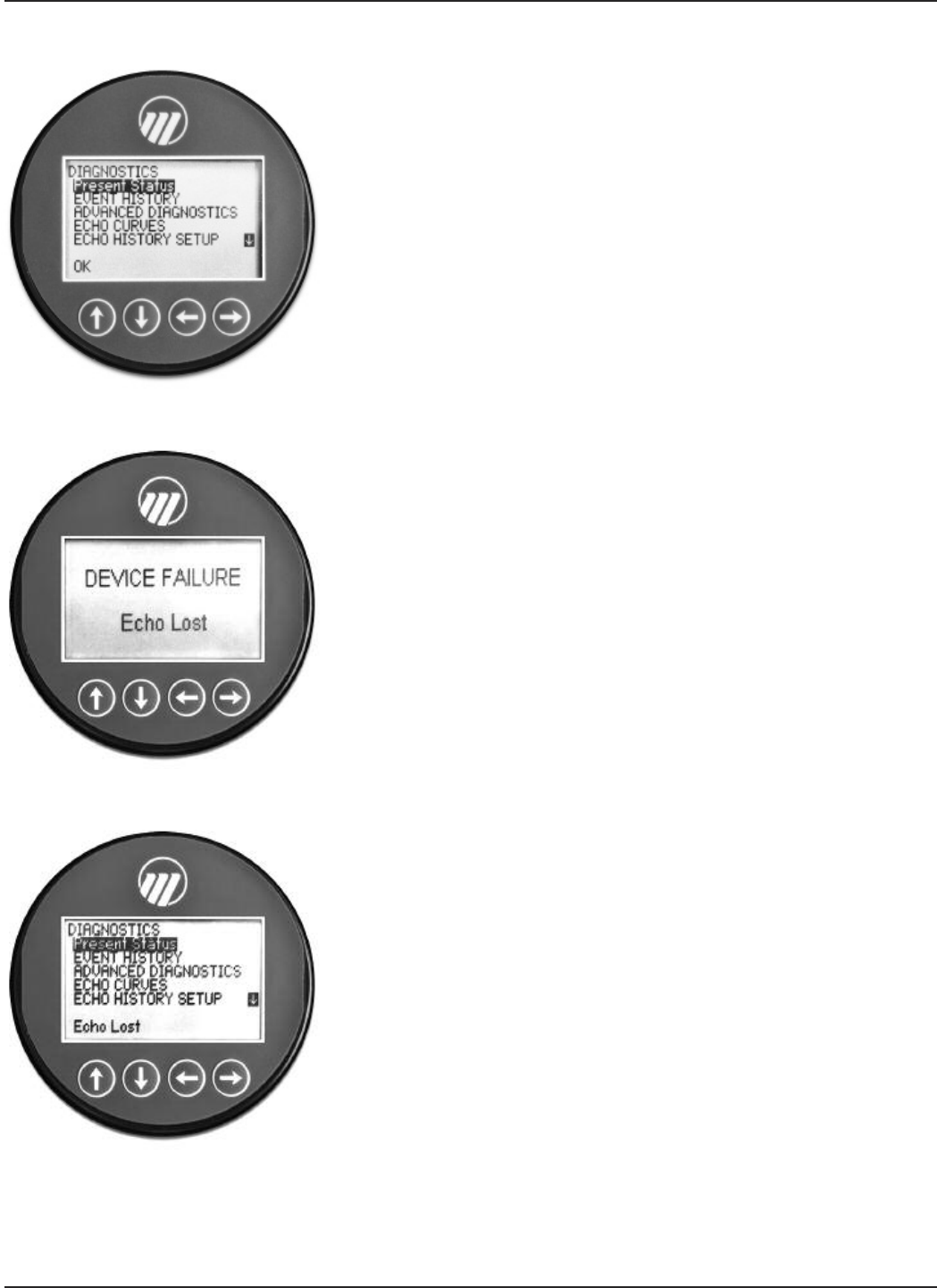
48 58-603 Pulsar®Model R86 Radar Transmitter
When the transmitter is operating normally and the high-
light cursor is positioned on Present Status, the bottom
LCD line displays “OK” because no diagnostic indicators
are active.
EVENT HISTORY – This menu displays the last twenty
events related to configuration and diagnostic event logging.
ADVANCED DIAGNOSTICS – This menu displays
parameters related to some of the advanced diagnostics
available within the Model R86.
INTERNAL VALUES – Displays read-only internal
parameters.
ELEC TEMPERATURES – Displays temperature
information as measured in the electronics module in
degrees F or C.
TRANSMITTER TESTS – Allows the user to
manually set the output current to a constant value.
This is a method for the user to verify operation of the
other equipment in the loop.
ECHO CURVES – This menu allows the user to display
the live Echo Curve on the LCD.

49
58-603 Pulsar®Model R86 Radar Transmitter
Priority Indicator Name Default
Category Explanation Remedy (Context Sensitive Help)
1Software Error Failure Unrecoverable error occurred in stored
program.
Contact MAGNETROL Technical Support.
2RAM Error Failure RAM (read/write) memory failing.
3ADC Error Failure Analog-to-digital converter failure.
4EEPROM Error Failure Non-volatile parameter storage failing.
5Analog Board
Error Failure Unrecoverable hardware failure.
6Analog Output
Error Failure
Actual loop current deviates from
commanded value. Analog output is
inaccurate.
Perform Adjust Analog Output
maintenance procedure.
7Spare Indicator 1 OK Reserved for future use.
8Default
Parameters
Saved parameters are set to default
values. Perform complete Device Configuration.
9Spare Indicator 2 OK Reserved for future use.
10 Spare Indicator 3 OK Reserved for future use.
11 No Fiducial Failure Reference signal too weak to detect.
Torque HF nut.
Clean gold pin on transmitter and socket
on antenna.
Check settings:
Fiducial Gain
Window
Increase Fid Gain.
Contact MAGNETROLTechnical Support.
12 Too Many Echoes Failure Excessive number of possible echoes
detected
Check Settings: Dielectric, Sensitivity.
Check Polarization.
13 Safety Zone Alarm Failure Risk of echo loss if liquid rises above
Blocking Distance.
Ensure that liquid cannot reach Blocking
Distance.
14 Echo Lost Failure No signal detected.
Check settings:
Dielectric Range
Increase Sensitivity.
View Echo Curve.
15 Spare Indicator 4 OK Reserved for future use
16 Config Conflict Failure Measurement type and primary variable
selection parameters are inconsistent.
Confirm proper configuration.
Check Measurement Type.
17 High Volume Alarm Failure
Volume calculated from Level reading
exceeds capacity of vessel or custom
table.
Check settings:
Vessel Dimensions,
Custom Table entries
3.4.4 Diagnostic Indicator Table
Shown below and at right is a listing of the Model R86 diagnostic indicators, showing their priority,
explanations and recommended remedies. (Priority 1 is highest priority.)

50 58-603 Pulsar®Model R86 Radar Transmitter
Priority Indicator Name Default
Category Explanation Remedy
18 Spare Indicator 5 OK Reserved for future use.
19 Initializing Function
Check
Distance measurement is inaccurate
while internal filters are settling.
Standard start-up message. Wait for
up to 10 seconds.
20 Config Changed Function
Check
A parameter has been modified from
the User Interface.
If desired, reset Config Changed
indicator in ADVANCED CONFIG
menu.
21 Spare Indicator 6 OK Reserved for future use.
22 Ramp Slope Error Failure
Internal signal timing out of limits
causing inaccurate distance
measurement.
Check accuracy of Level reading.
Replace transmitter electronics.
Contact MAGNETROL Technical Support.
23 High Elec Temp Out of Spec
Electronics too hot. May compromise
level measurement or damage
instrument.
Shield transmitter from heat source or
increase air circulation. Locate
transmitter remotely in a cooler area.
24 Low Elec Temp Out of Spec
Electronics too cold. May compromise
level measurement or damage
instrument.
Insulate transmitter.
Locate transmitter remotely in a
warmer area.
25 Calibration Req’d Out of Spec
Factory calibration has been lost.
Measurement accuracy may be
diminished.
Return transmitter to factory for
recalibration.
26 Echo Reject
Invalid Out of Spec
Echo Rejection inoperative. May report
erroneous Level readings. Upr Echo
may be lost.
Save a fresh Echo Rejection Curve.
27 Spare Indicator 7 OK Reserved for future use.
28 Inferred Level Out of Spec
Level inferred to have entered Blocking
Region if echo lost within Max Distance
Jump of Top or Bottom Blocking
Region.
Verify level reading; if incorrect, check
configuration.
29 Adjust Analog Out Out of Spec Loop current is inaccurate. Perform Adjust Analog Output
maintenance procedure.
30 Low Supply
Voltage Out of Spec Loop current may be incorrect at higher
values. Analog output is inaccurate.
Verify loop resistance.
Replace loop power supply.
31 Spare Indicator 8 OK Reserved for future use.
32 Max Jump Exceeded Maintenance
Required
Transmitter has jumped to an echo at
location that exceeds “Max Level
Jump” from previous echo location.
Check settings:
Dielectric Range
Sensitivity
View Echo Curve.
33 Low Echo Margin Maintenance
Required
Signal Margin is less than allowable
minimum.
Check settings:
Dielectric Range
Sensitivity
View Echo Curve.
34 High Surface
Velocity
Maintenance
Required
Measured Surface Velocity greater than
Max Surface Velocity derived from
configured Rate of Change.
Confirm actual rate of change. Adjust
rate of change setting, if needed.
35 Spare Indicator 9 OK Reserved for future use.
36 Spare Indicator 10 OK Reserved for future use.
37 Sequence Record OK A Sequence Record number has been
stored in Event Log.
If desired, report Sequence Record
number to factory.
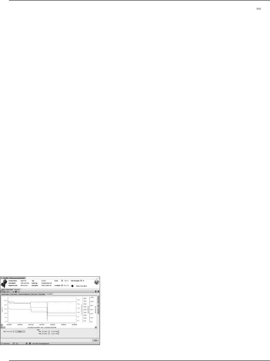
51
58-603 Pulsar®Model R86 Radar Transmitter
3.4.5 Additional Diagnostic/Trouble Shooting Capabilities
3.4.5.1 Echo History Setup
The Model R86 contains the unique and powerful feature
that allows waveforms to be automatically captured based
on Diagnostic Events, Time or both. This menu contains
those parameters that configure that feature.
Eleven (11) waveforms can be saved directly into the trans-
mitter.
• Nine (9) Troubleshooting Curves
• One (1) Echo Rejection Curve
• One (1) Reference Curve
3.4.5.2 Event History
As a means for improved troubleshooting capability, a
record of significant diagnostic events is stored with time
and date stamps. A real-time on-board clock (which must
be set by the operator), will maintain the current time.
3.4.5.3 Context-sensitive Help
NOTE: Context-sensitive HELP is available for all menu items. With the
menu item highlighted, hold down the ➪ENTER key for two
seconds. Use UP and DOWN for navigation.
Descriptive information relevant to the highlighted parameter
in the menu will be accessible via the local display and
remote host interfaces. This will most often be a parameter-
related screen, but could also be information about menus,
actions (for example, Loop [Analog Output] Test, resets of
various types), diagnostic indicators, etc.
For example: Dielectric Range — Selects the range bounding
the dielectric constant of the medium in vessel. Some ranges
may not be selectable depending on the antenna model.
3.4.5.4 Trend Data
Another feature of the Model R86 is the ability to log several
measured values (selectable from any of the primary,
secondary, or supplemental measured values) at a config-
urable rate (for example, once every five minutes) for a
period ranging from several hours to a number of days
(depending on the configured sample rate and number of
values to be recorded). The data will be stored in non-
volatile memory in the transmitter with date and time
information for subsequent retrieval and visualization using
the associated Model R86 DTM.
TREND DATA – A 15-minute trend of the PV can be
displayed on the LCD.
➪
➪
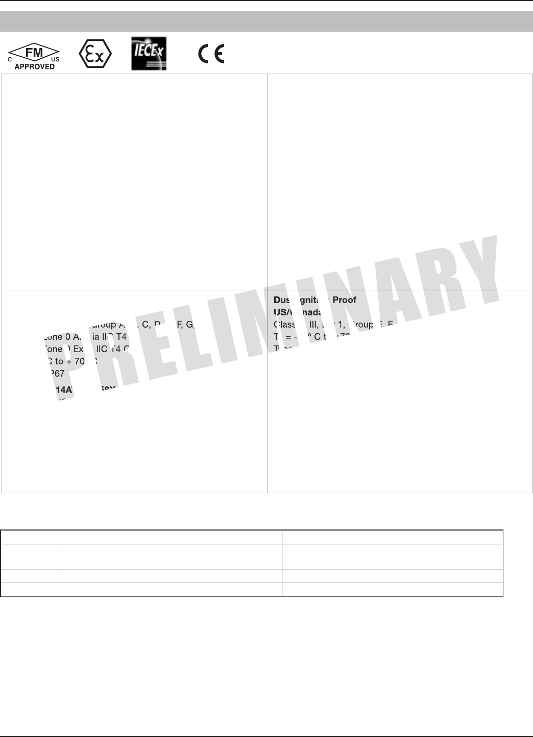
52 58-603 Pulsar®Model R86 Radar Transmitter
3.5 Agency Approvals
These units are in compliance with the RED-directive 2014/30/EU, the
PED-directive 2014/68/EU and the ATEX directive 2014/34/EU.
Explosion Proof
US/Canada:
Class I, Div 1, Group B, C, D, T4
Class I, Zone 1 A Ex db ia IIB+H2 T4
Class I, Zone 1 Ex d ia IIB+H2 T4
Ta = -40 ºC to +70 ºC
Type 4X, IP67
Flame Proof
ATEX – FM14ATEX0058X
II 1/2 G Ex db ia IIB + H2 T4… T1 Gb/Ga
Ta = -40 ºC to +70 ºC
IP67
IEC- IECEx FMG 15.0034X
Ex db ia IIB + H2 T4…T1 Gb/Ga
Ta = -40 ºC to +70 ºC
IP67
Non- Incendive
US/Canada:
Class I, II, III, Div 2, Group A, B, C, D, E, F, G, T6
Class 1, Zone 2 AEx nA ia IIC T4
Class 1, Zone 2 Ex nA ia IIC T4
Ta = -40 ºC to +70 ºC
Type 4X, IP67
ATEX - FM14ATEX0058X
II 3 G Ex nA IIC Gc T6
Ta = -15 ºC to +70 ºC
IP67
IEC – IECEx FMG 15.0034X
Ex nA IIC Gc T6
Ta = -15 ºC to + 70 ºC
IP67
Intrinsically Safe
US/Canada:
Class I, II, III, Div 1, Group A, B, C, D, E, F, G, T4
Class I, Zone 0 AEx ia IIC T4
Class I, Zone 0 Ex ia IIC T4 Ga
Ta =-40 ºC to + 70 ºC
Type 4X, IP67
ATEX – FM14ATEX0058X:
II 1 G Ex ia IIC T4 Ga
Ta = -40 ºC to +70 ºC
IP67
IEC – IECEx FMG 15.0034X:
Ex ia IIC T4 Ga
Ta = -40 ºC to +70 ºC
IP67
Dust Ignition Proof
US/Canada:
Class II, III, Div 1, Group E, F, and G, T5
Ta = -15º C to +70º C
Type 4X, IP67
ATEX – FM14ATEX0059X:
II 2 D Ex ia tb IIIC T110º C Db
Ta = -15º C to +70º C
IP67
IEC – IECEx FMG 15.0034X:
Ex ia tb IIIC 100º C Db
Ex ia IIIC T85º C to T450º C Da
Ta = -15º C to +70º C
IP67
Telecommunications Approvals
Agency In-Tank Out of Tank
FCC 47 CFR, Part 15, Subpart B, Class B
Unintentional Radiators Part 15, Subpart C, Section 15.256
ISED RSS-211 RSS-211
ETSI EN 302 372 V2.1.1 (2016-12) (Future)

53
58-603 Pulsar®Model R86 Radar Transmitter
FM3600:2011, FM3610:2010, FM3611:2004, FM3615:2006, FM3616:2011, FM3810:2005, ANSI/ISA60079-0:2013,
ANSI/ISA 60079-1:2015, ANSI/ISA 60079-11:2013, ANSI/ISA 60079-15:2012, ANSI/ISA 60079-26:2011, NEMA 250:2003, ANSI/IEC 60529:2004,
C22.2 No. 0.4:2009, C22.2 No. 0.5:2008, C22.2 No. 30:2007, C22.2 No. 94:2001, C22.2 No. 213:2012, C22.2 No. 1010.1:2009, CAN/CSA
60079-0:2011, CAN/CSA 60079-1:2011, CAN/CSA 60079-11:2014, CAN/CSA 60079-15:2012, C22.2 No. 60529:2005, EN60079-0:2012,
EN60079-1:2014, EN60079-11:2012, EN60079-15:2010, EN60079-26:2007, EN60079-31:2009, EN60529+A1:1991-2000, IEC60079-0:2011,
IEC60079-1:2014, IEC60079-11:2011, IEC60079-15:2010, IEC60079-26:2006, IEC60079-31:2008
“This equipment with chargeable non-conductive parts, e.g. enclosure’s paint and antenna use PTFE, Co-polymer Polypropylene or Noryl
En265, is provided with a warning label referring to the safety measures that must be taken if there is electrostatic charging during operation.
For use in hazardous area, the equipment and side to be installed, e.g. tank, must be connected to earth and be attention to not only the meas-
uring object, e.g. liquids, gases, powders and etc., but also the related conditions, e.g. tank container, vessel and etc. (According to IEC 60079-
32-1).”
SPECIAL CONDITIONS OF USE:
1. For U.S. — The sensor probes are suitable for connections to Class I, II, III, Division 1, Groups A, B, C, D, E, F, and G and Class I, Zone
0, Group IIC Hazardous (Classified) Locations
2. For Canada — The sensor probes are suitable for connections to Class I, II, III, Division 1, Groups A, B, C, D, E, F, and G and
Class I, Zone 0, Group IIC Hazardous Locations
3. For IECEx — The sensor probes are rated with an Equipment Protection Level of Ga and Da
4. For ATEX — The sensor probes maintain a category 1G and 1D rating.
FCC (ID# LPN-R86) Compliance Statement:
§15.209 The 11⁄2" and 2" horns can be used only in tanks.
§15.105 Information to the user.
(b) For a Class B digital device or peripheral, the instructions furnished the user shall include the following or similar statement, placed in a
prominent location in the text of the manual:
Note: This equipment has been tested and found to comply with the limits for a Class B digital device, pursuant to part 15 of the FCC Rules.
These limits are designed to provide reasonable protection against harmful interference in a residential installation. This equipment generates,
uses and can radiate radio frequency energy and, if not installed and used in accordance with the instructions, may cause harmful interference
to radio communications. However, there is no guarantee that interference will not occur in a particular installation. If this equipment does cause
harmful interference to radio or television reception, which can be determined by turning the equipment off and on, the user is encouraged to try
to correct the interference by one or more of the following measures:
—Reorient or relocate the receiving antenna.
—Increase the separation between the equipment and receiver.
—Connect the equipment into an outlet on a circuit different from that to which the receiver is connected.
—Consult the dealer or an experienced radio/TV technician for help.
(i) The installation of the LPR/TLPR device shall be done by trained installers, in strict compliance with the manufacturer’s instructions.
(ii) The use of this device is on a “no-interference, no-protection” basis. That is, the user shall accept operations of high-powered radar in the
same frequency band which may interfere with or damage this device. However, devices found to interfere with primary licensing operations will
be required to be removed at the user’s expense.
This device shall be installed and operated in a completely enclosed container to prevent RF emissions, which can otherwise interfere with aero-
nautical navigation.
This device complies with Industry Canada’s licence-exempt RSSs. Operation is subject to the following two conditions:
(1) This device may not cause interference; and
(2) This device must accept any interference, including interference that may cause undesired operation of the device
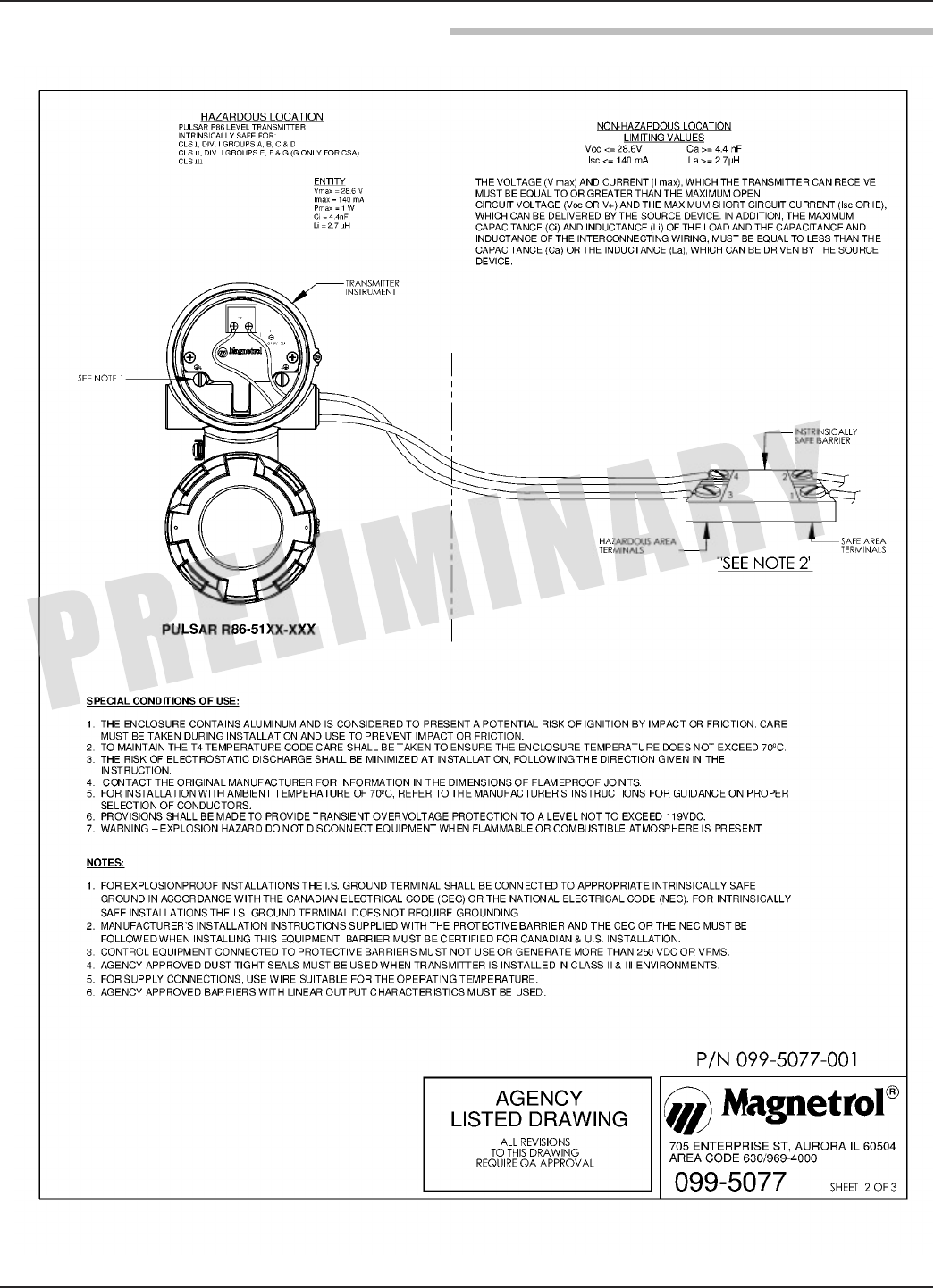
54 58-603 Pulsar®Model R86 Radar Transmitter
3.5.1 Agency Drawing and Entity Parameters
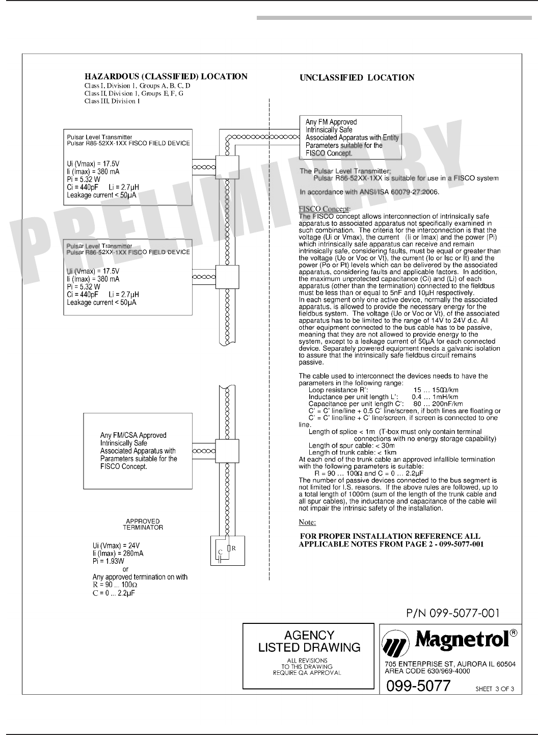
55
58-603 Pulsar®Model R86 Radar Transmitter
3.5.1 Agency Drawing and Entity Parameters
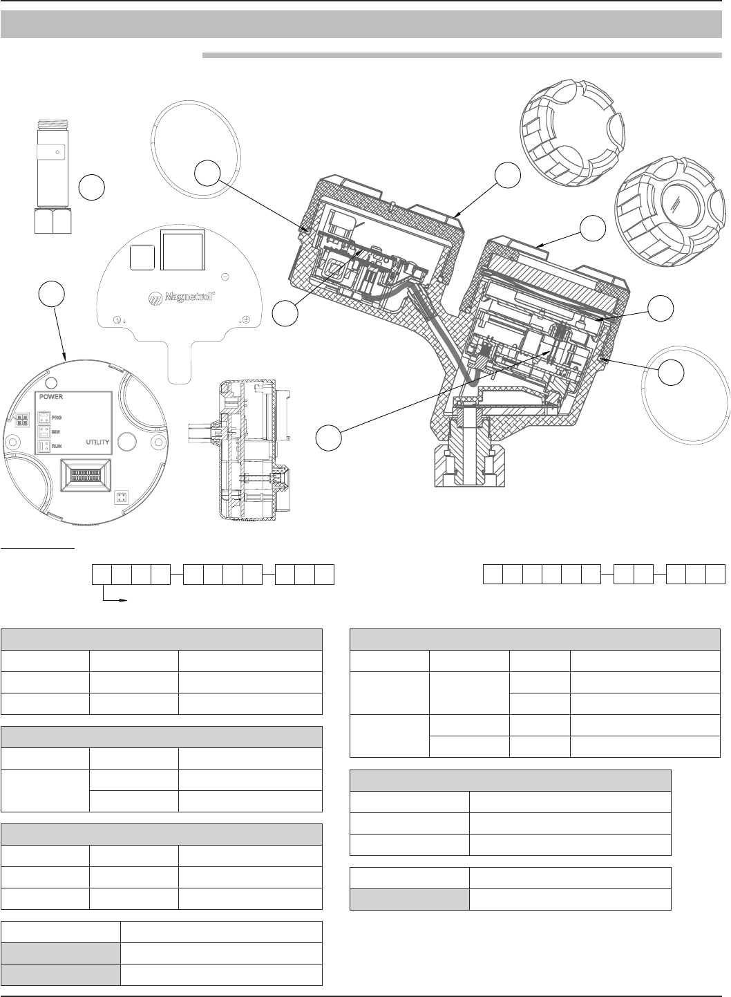
56 58-603 Pulsar®Model R86 Radar Transmitter
(1) Electronic Module
Digit 5 Digit 6 Replacement Part
1 1 Z31-2864-001
2 0 Z31-2864-002
(2) Display Module
Digit 5 Digit 7 Replacement Part
1 or 2 0 N/A
A Z31-2850-001
(3) Wiring PC Board
Digit 5 Digit 6 Replacement Part
1 1 Z30-9180-001
2 0 Z30-9166-003
Replacement Part
(4) O-ring 012-2601-237
(5) O-ring 012-2601-237
Replacement Part
(8) Heat Extension 032-6922-001
(6) Housing Cover
Digit 7 Digit 8 Digit 9 Replacement Part
0 all 1 004-9225-002
2 004-9225-003
Aall 1 036-4413-013
all 2 036-4413-016
(7) Housing Cover
Digit 9 Replacement Part
1 004-9225-002
2 004-9225-003
6
7
5
8
1
J1
+-
CURRENT LOOP
TB1
R
7 0 67 7 7 7 7 7 7 7
R
X = product with a non-standard customer requirement See nameplate, always provide complete part number and
serial number when ordering spares.
865
Digit:
Serial Number:
Part Number:
Electronics:
123 456 89107
1
32
4
3.6 Parts
3.6.1 Replacement Parts

57
58-603 Pulsar®Model R86 Radar Transmitter
3.7 Specifications
3.7.1 Functional – Transmitter
System Design
Measurement Principle Pulse Burst Radar 26 GHz
Input
Measured Variable Level, determined by the time-of-flight of radar pulse reflections
Span0.5 to 130 feet (0.2 to 40 meters)
Output
Type 4 to 20 mA with HART: 3.8 mA to 20.5 mA useable (per NAMUR NE43)
FOUNDATIONfieldbus™: H1 (ITK Ver. 6.2.0)
Resolution Analog: .003 mA
Digital Display: 1 mm
Loop Resistance GP/IS: 591 ohms @ 24 VDC and 22 mA
XP/Flameproof:500 ohms @ 24 VDC and 22 mA
Diagnostic Alarm Selectable: 3.6 mA, 22 mA(meets requirements of NAMUR NE 43), or HOLD last output
Diagnostic Indication Meets requirements of NAMUR NE107
DampingAdjustable 0-10
User Interface
Keypad 4-button menu-driven data entry
DisplayGraphic Liquid Crystal Display
Digital Communication HART Version 7–with Field Communicator, FOUNDATIONfieldbus™, AMS, or FDT
DTM (PACTware™), EDDL
Menu LanguagesTransmitter LCD: English, French, German, Spanish, Russian
HART DD: English, French, German, Spanish, Russian, Chinese, Portuguese
FOUNDATIONfieldbus Host System: English
Power (Measured at instrument terminals) HART: General Purpose (Weather proof)/Intrinsically Safe/Explosion-proof:
11 VDC minimum at terminals under certain conditions
FOUNDATIONfieldbus™: 9 to 17.5 VDC
FISCO, FNICO, Explosion Proof, General Purpose and Weather Proof
Housing
MaterialIP67/die-cast aluminum A413 (<0.6% copper); optional stainless steel
Net/Gross Weight Aluminum: 4.5 lbs. (2.0 kg)
Stainless Steel:10.0 lbs. (4.50 kg)
Overall Dimensions See Section 3.7.6
Cable Entry1⁄2" NPT or M20
SIL 2 Hardware(Safety Integrity Level) Safe Failure Fraction = 93.2% (HART only)
Functional Safety to SIL 2 as 1oo1 in accordance with IEC 61508
(Full FMEDA report available upon request)

58 58-603 Pulsar®Model R86 Radar Transmitter
Operating Temperature-40 to +175 °F (-40 to +80 °C); LCD viewable -5 to +160 °F (-20 to +70 °C)
Storage Temperature-50 to +185 °F (-45 to +85 °C)
Humidity0–99%, non-condensing
Electromagnetic CompatibilityMeets CE requirement (EN 61326) and NAMUR NE 21
Surge Protection Meets CE EN 61326 (1000V)
Shock/VibrationANSI/ISA-S71.03 Class SA1 (Shock); ANSI/ISA-S71.03 Class VC2 (Vibration)
Reference ConditionsReflection from ideal reflector at +70 °F (+20 °C)
Linearity ±0.1 inch (3 mm) or 0.1% of tank height (whichever is greater)
Measured Error±0.1 inch (3 mm) or 0.1% of tank height (whichever is greater)
(Performance will degrade slightly within 60" (1.5 m) of antenna)
Resolution 0.1 inch or 1mm
Repeatability±0.1 inch (3 mm) or 0.05% of tank height (whichever is greater)
Response Time<2 seconds (configuration dependent)
Initialization Time< 30 seconds
Ambient Temperature EffectDigitalAverage 0.12 inch (3 mm) / 10 K, max of ±0.4 inch (10 mm) over the entire
temperature range -40 to +175 °F (-40 to +80 °C)
Analog Current Output (additional error with reference to 16 mA span)
Average 0.03% / 10 K. max 0.45% over entire temperature range
-40 to +175 °F (-40 to +80 °C)
Maximum Rate of Change180 inches (450 cm)/minute
FOUNDATIONfieldbus™:ITK Version 6.2.0
H1 Device Class Link Master (LAS)— selectable ON/OFF
H1 Profile Class 31PS, 32L
Function Blocks (8) Al, (3) Transducer, (1) Resource, (2) PID (1) Arithmetic,
(1) Signal Characterizer, (1) Input Selector, (1) Integrator
Quiescent Current 17 mA
Execution Time10 ms (15 ms PID Block)
Device Revision 01
DD Version 0x01
3.7 Specifications
3.7.2 Functional – Environment
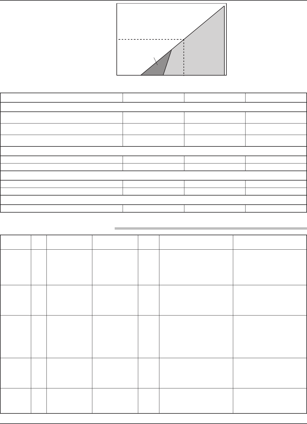
59
58-603 Pulsar®Model R86 Radar Transmitter
Operational Mode Current Consumption Vmin Vmax
HART
General Purpose 4mA
20mA
16.25V
11V
36V
36V
Intrinsically Safe 4mA
20mA
16.25V
11V
28.6V
28.6V
Explosion Proof 4mA
20mA
16.25V
11V
36V
36V
Fixed Current-Solar Power Operation (PV transmitter via HART)
General Purpose 10mA➀11V 36V
Intrinsically Safe 10mA➀11V 28.6V
HART Multi-Drop Mode (Fixed Current)
Standard 4mA➀16.25V 36V
Intrinsically Safe 4mA➀16.25V 28.6V
FOUNDATION fieldbus™ (Future)
Supply Voltage 9V to 17.5V 9V to 17.5V 9V to 17.5V
3.7.2.2 Transmitter Terminal Voltage
3.7.3 O-ring (seal) Selection Chart
3.7.2.1 Safe Operating Area
0
Vsupply
Typical HART
4-20 mA
Operating Area
Digital Solar Mode
16.25 V
591
Ω
24 V 36 V
Loop
R
11 V
➀ Start-up current 12 mA minimum
Material Code
Maximum
Temperature
Maximum
Pressure
Min.
Temp.
Recommended
For Use In
Not Recommended
For Use In
Viton®GFLT 0 +400 °F @ 232 psi
(+200 °C @ 16 bar)
750 psi @ +70 °F
(51.7 bar @ +20 °C)
-40 °F
(-40 °C) General purpose, ethylene
Ketones (MEK, acetone),
skydrol fluids, amines, anhy-
drous ammonia, low molecular
weight esters and ethers, hot
hydrofluoric or chlorosulfuric
acids, sour HCs
Kalrez®4079 2 +400 °F @ 232 psi
+(200 °C @ 16 bar)
750 psi @ +70 °F
(51.7 bar @ +20 °C)
-40 °F
(-40 °C)
Inorganic and organic acids
(including HF and nitric),
aldehydes, ethylene, glycols,
organic oils, silicone oils, vinegar,
sour HCs
Black liquor, hot water/steam,
hot aliphatic amines, ethylene
oxide,propylene oxide, molten
sodium, molten potassium
➁
Simriz SZ485
(formerly
Aegis PF128)
8+400 °F @ 232 psi
+(200 °C @ 16 bar)
750 psi @ +70 °F
(51.7 bar @ +20 °C)
-4 °F
(-20 °C)
Inorganic and organic acids
(including HF and nitric),
aldehydes, ethylene, glycols,
organic oils, silicone oils, vinegar,
sour HCs, steam, amines, ethyl-
ene oxide, propylene oxide,
NACE applications
Black liquor, Freon 43, Freon 75,
Galden, KEL-F liquid, molten
sodium, molten potassium
Kalrez®6375 A 400 °F @ 232 psi
(200 °C @ 16 bar)
750 psi 70 °F
(51.7 bar @ 20 °C)
-40 °F
(-40 °C)
Inorganic and organic acids
(including hydro fluids and nitric),
aldehydes, ethylene, organic oils,
glycols, silicone oils, vinegar,
sour HCs
Hot water/steam, hot aliphatic
amines, ethylene oxide, propylene
oxide
Quartz N +750 °F @ 1375 psi
(+400 °C @ 34.8 bar)
2320 psi @ 70 °F
(160 bar @ +20 °C)
-100 °F
(-70 °C)
General high temperature/high
pressure applications,
hydrocarbons, full vacuum
(hermetic), ammonia, chlorine
Hot alkaline solutions HF acid,
media with ph>12, direct exposure
to saturated steam
➁Maximum +300 °F (+150 °C) for use on steam.
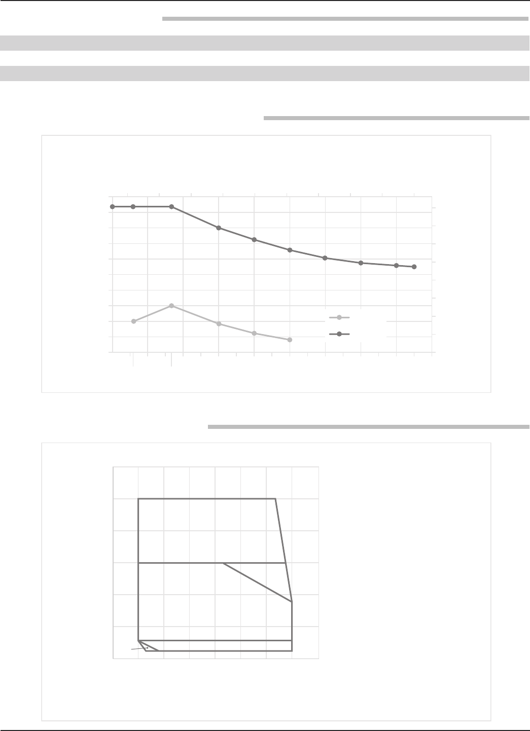
60 58-603 Pulsar®Model R86 Radar Transmitter
3.7.4 Functional – Antenna
3.7.5 Antenna Pressure / Temperature Ratings
3.7.6 Operating Temperature Range
Materials 316 SS or Hastelloy C PTFE, O-rings or Quartz
Maximum Process Temperature +750 °F @ 1375 psi (+400 °C @ 94.8 bar)
Maximum Process Pressure -14.7 to 2320 psi @ +70 °F (-1.0 to 160 bar @ +20 °C)
Minimum Dielectric (application dependent) 1.7 (1.4 with stillwells)
0
500
250
-40 70
750
1000
1500
1250
2000
2250
1750
2500
-100 0 100 200 300 400 500 600 700 800
Pressure (psig)
0
20
40
60
80
100
120
140
160
-50 0 50 100 150 200 250 300 350 400
Pressure (bar)
Temperature (°F)
Temperature (°C)
Antenna Pressure Ratings
PTFE
QUARTZ
Ambient Temperature °F (°C)
-76
(-60)
-148
(-100)
32
(0)
212
(100)
392
(200)
572
(300)
752
(400)
932
(500)
-40
(-40)
-4
(-20)
32
(0)
68
(20)
104
(40)
140
(60)
176
(80)
212
(100)
Safe Operating Regions
A: Standard Seal, PTFE
B: Standard Seal with Extension
(P/N 032-6922-001)
C: HTHP Seal
D: HTHP Seal with Extension
(P/N 032-6922-001)
Process Temperature °F (°C)
D
B, C, D
B, D
D
A, B, C, D
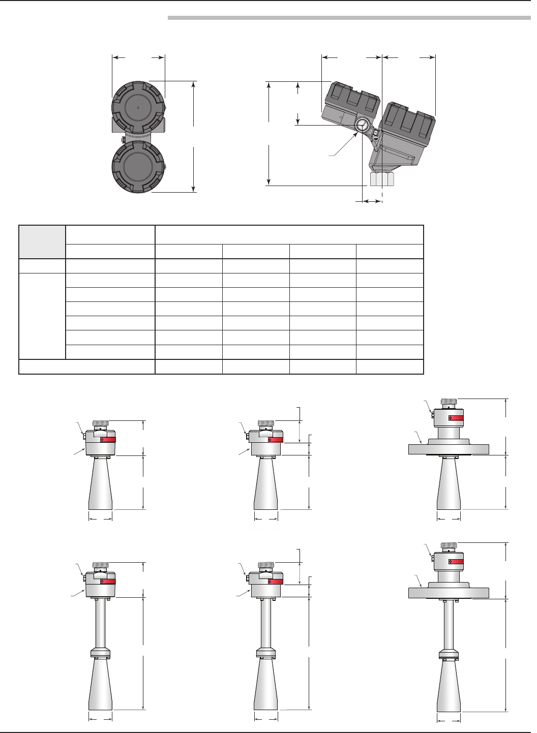
61
58-603 Pulsar®Model R86 Radar Transmitter
3.7.7 Physical – Inches (mm)
3.96
(101)
4.51
(115)
7.77
(197)
3.22
(82)
½" NPT
or M20
3.98
(101)
1.46
(37)
8.34
(212)
TRANSMITTER
Model Number 3rd Digit (Horn Size)
11th Digit (Extension) 1(11⁄2") 2(2") 3(3") 4(4")
Dim. H 0(None) 3.2 (81) 4.5 (114) 8.5 (216) 11.5 (292)
Dim. L
1(4") 6 (152) — — —
2(8") 8 (203) 8.3 (211) — —
3(12") 12 (305) 12 (305) 12.4 (315) 14.4 (366)
4(24") 24 (610) 24 (610) 24 (610) 24 (610)
5(48") 48 (1219) 48 (1219) 48 (1219) 48 (1219)
6(72") 72 (1829) 72 (1829) 72 (1829) 72 (1829)
Dim. D 1.56 (40) 1.89 (48) 2.95 (75) 3.74 (95)
HORN ANTENNA
1/8" NPT
Flushing Port Option
1/8" NPT
Flushing Port Option
1/8" NPT
Flushing Port Option
1/8" NPT
Flushing Port Option
1/8" NPT
Flushing Port Option
Flange
NPT
BSP
BSP
NPT
D D D
D D D
2.81
(71)
H
1/8" NPT
Flushing Port Option
Flange
2.81
(71)
L
1.00
(25)
1.81
(46)
H
1.00
(25)
1.81
(46)
L
4.56
(116)
H
4.56
(116)
L
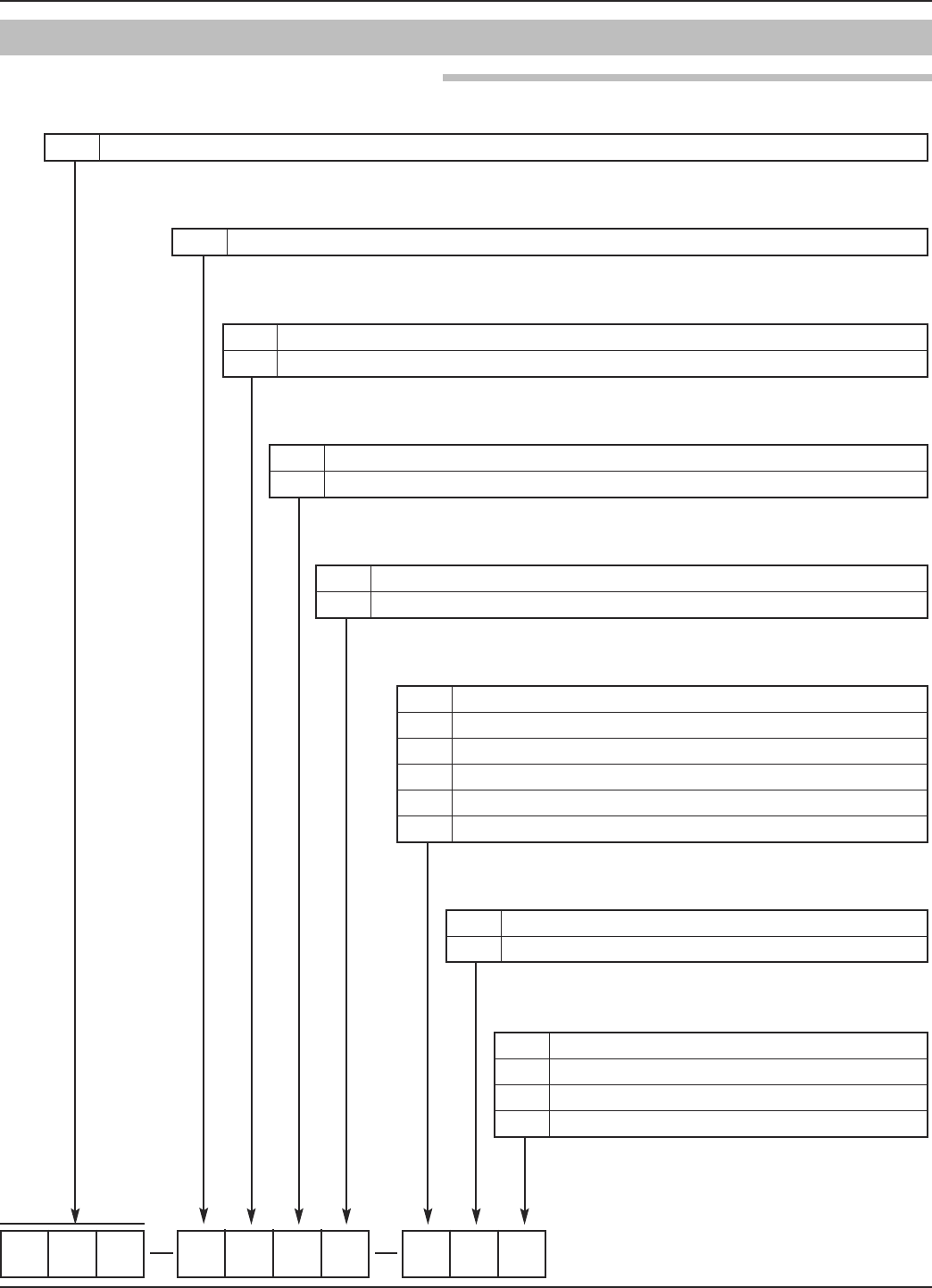
62 58-603 Pulsar®Model R86 Radar Transmitter
3.8 Model Numbers
3.8.1 PULSAR Model R86 Radar Transmitter
R86 5
10 |CONDUIT CONNECTION
01⁄2" NPT
1 M20
21⁄2" NPT with sunshade
3 M20 with sunshade
1–3 | MEASUREMENT SYSTEM
R 8 6 Through-Air Radar Level Transmitter - 26 GHz Pulse Burst Radar
4 | POWER
5 24 VDC, Two Wire
5 | SIGNAL OUTPUT
1 4-20 mA with HART
2 Foundation fieldbus™H1
6 | SAFETY OPTIONS
0 None (FOUNDATION fieldbus only, 5th digit = 2)
1 SIL 2 Hardware - HART only (5th digit = 1)
7|ACCESSORIES/MOUNTING
0 No Digital Display and Keypad - Integral
A Digital Display and Keypad - Integral
8 | CLASSIFICATION
0 General Purpose, Weatherproof (IP 67)
1 Intrinsically Safe (FM & CSA)
3 Explosion-proof (FM & CSA)
A Intrinsically Safe (ATEX/IEC)
B Flame-proof (ATEX/IEC)
C Non-sparking (ATEX)
9 | HOUSING
1 Die Cast Aluminum, Dual Compartment, 20-degree
2 Investment Cast, 316ss, Dual Compartment, 20-degree
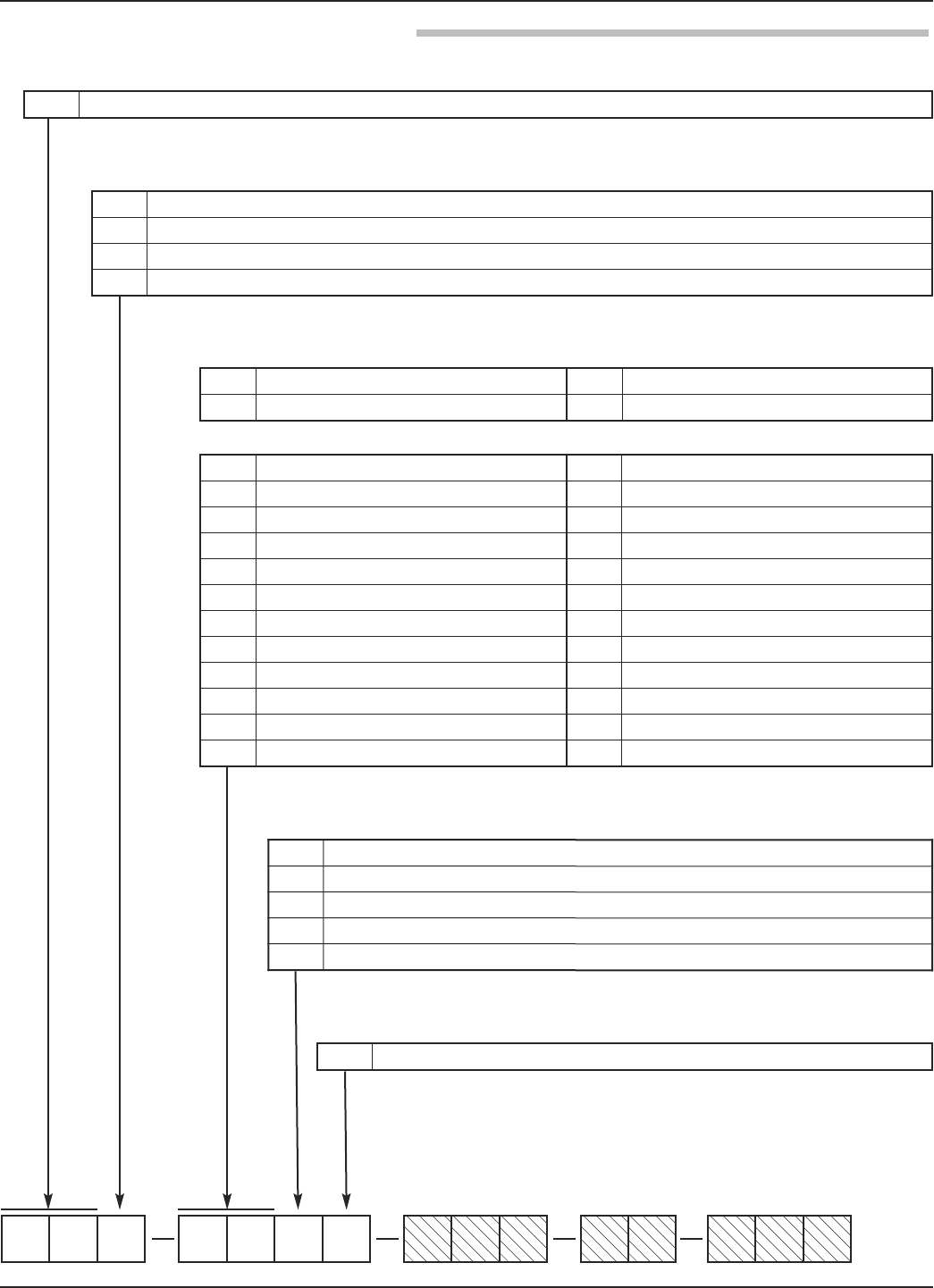
63
58-603 Pulsar®Model R86 Radar Transmitter
3.8.2 PULSAR Model R86 Radar Antenna
RB 0
12 3 4 56 7 8 910 11 12 13 14 15
3|CONFIGURATION/STYLE
1 11⁄2" Horn (inside tanks only)
2 2" Horn (inside tanks only)
3 3" Horn (inside tanks or outside tanks for FCC and Canada)
44" Horn (inside tanks or outside tanks for FCC and Canada)
4–5 |PROCESS CONNECTION - SIZE/TYPE
ANSI Flanges EN (DIN) Flanges
1–2 | TECHNOLOGY
R B PULSAR Radar Antennas - 26 GHz
31 11⁄2" NPT thread 41 2" NPT Thread
32 11⁄2" BSP (G 11⁄2") thread 42 2" BSP (G2") Thread
43 2" 150# ANSI raised face flange DA DN 50, PN 16 EN 1092-1 Type A
44 2" 300# ANSI raised face flange DB DN 50, PN 25/40 EN 1092-1 Type A
45 2" 600# ANSI raised face flange DD DN 50, PN 63 EN 1092-1 Type B2
53 3" 150# ANSI raised face flange EA DN 80, PN 16 EN 1092-1 Type A
54 3" 300# ANSI raised face flange EB DN 80, PN 25/40 EN 1092-1 Type A
55 3" 600# ANSI raised face flange ED DN 80, PN 63 EN 1092-1 Type B2
63 4" 150# ANSI raised face flange FA DN 100, PN 16 EN 1092-1 Type A
64 4" 300# ANSI rased face flange FB DN 100, PN 25/40 EN 1092-1 Type A
65 4" 300# ANSI raised face flange FD DN 100, PN 63 EN 1092-1 Type B2
73 6" 150# ANSI raised face flange GA DN 150, PN 16 EN 1092-1 Type A
74 6" 300# ANSI raised face flange GB DN 150, PN 25/40 EN 1092-1 Type A
75 6" 600# ANSI raised face flange GD DN 150, PN 63 EN 1092-1 Type B2
6 | CONSTRUCTION CODES
0Industrial
K ASME B31.1
LASME B31.3
MASME B31.3 & NACE MR0175 / MR0103
NNACE MR0175 / MR0103
7 | FLANGE OPTIONS
0 None
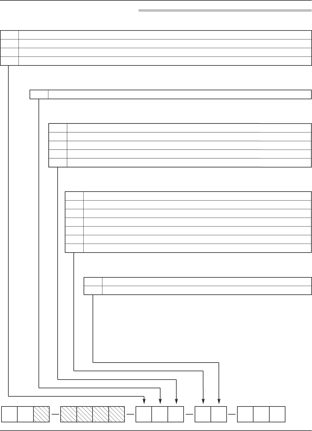
64 58-603 Pulsar®Model R86 Radar Transmitter
3.8.2 PULSAR Model R86 Radar Antenna
RB 0000
12 3 4 56 7 8 910 11 12 13 14 15
A 316SS/316L SS
B Hastelloy C
R316SS/316L SS with Carbon Steel Flange
S Hastelloy C with Carbon Steel Flange
8 | MATERIAL OF CONSTRUCTION - MFG/NUT/ROD/INSULATION
9 | FUTURE
0
10 | O-RING MATERIALS/SEAL OPTIONS
0Viton GFLT
2Kalrez 4079
8Simriz SZ485 (formerly Aegis PF128) — NACE
AKalrez 6375
NNone - Quartz seal
0 None
1 For nozzle height ≤ 4" (100 mm)
2 For nozzle height ≤ 8" (200 mm)
3 For nozzle height ≤ 12" (300 mm)
4 For nozzle height ≤ 24" (600 mm)
5 For nozzle height ≤ 48" (1200 mm)
6 For nozzle height ≤ 72" (1800 mm)
11 | ANTENNA EXTENSIONS
12 | SPECIAL OPTIONS
0 None
11⁄8" Flushing Connection
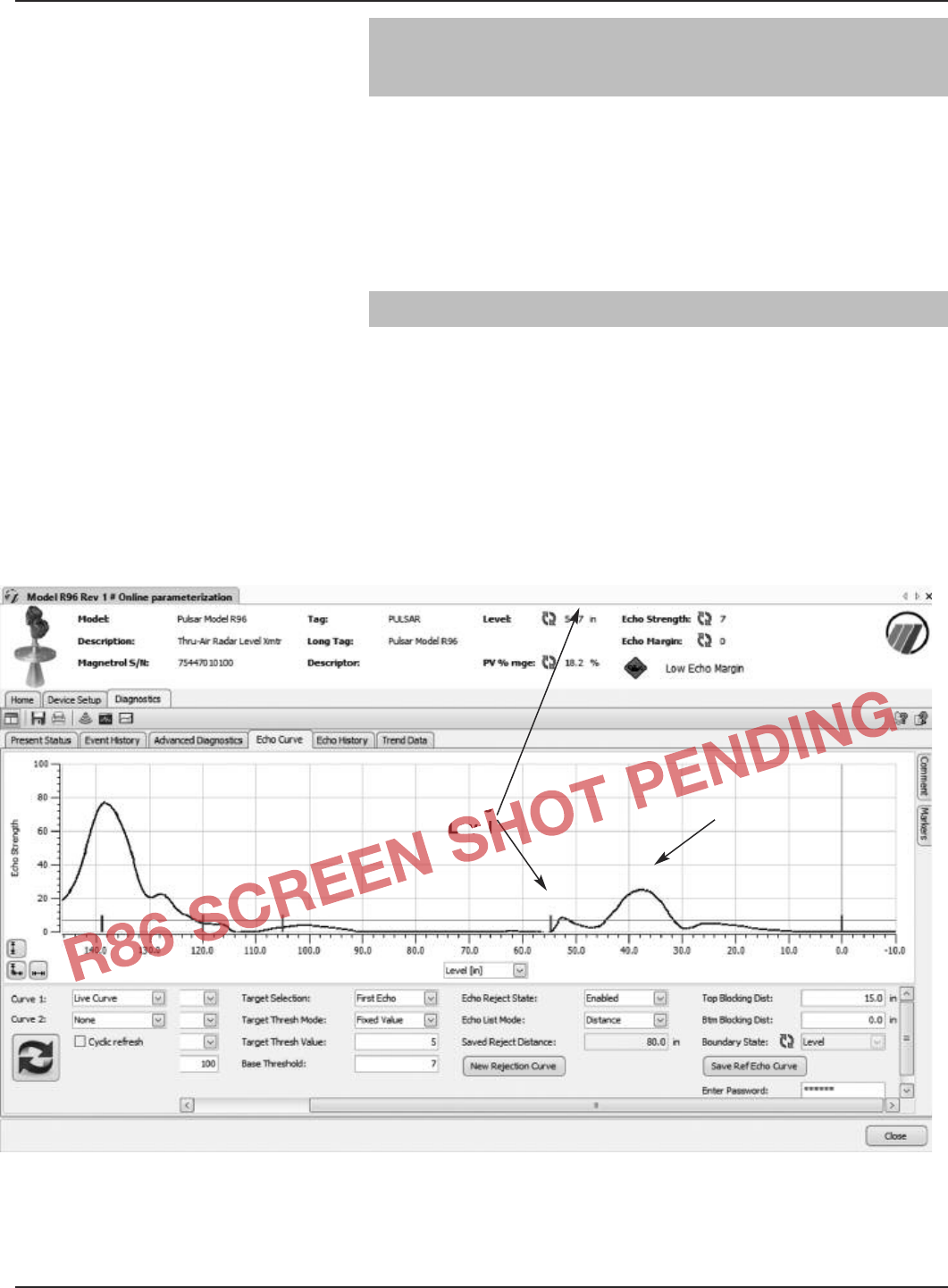
65
58-603 Pulsar®Model R86 Radar Transmitter
4.0 Advanced Configuration/
Troubleshooting Techniques
This section contains information regarding some of the
advanced configuration and troubleshooting capability con-
tained within the Model R86 transmitter. Some of these
diagnostic options are best suited for use with PACTware
and the Model R86 DTM, and should be implemented
only after contacting Magnetrol Technical Support.
4.1 Echo Rejection
After choosing a proper mounting location, another way to
ignore unwanted signals within the measuring range is by
utilizing the Echo Rejection feature.
Setup using DTM/PACTware™
Select the Diagnostics tab and then the Echo Curve tab.
After refreshing the waveform, click on the New Rejection
Curve button.
False
Level
Actual
Level
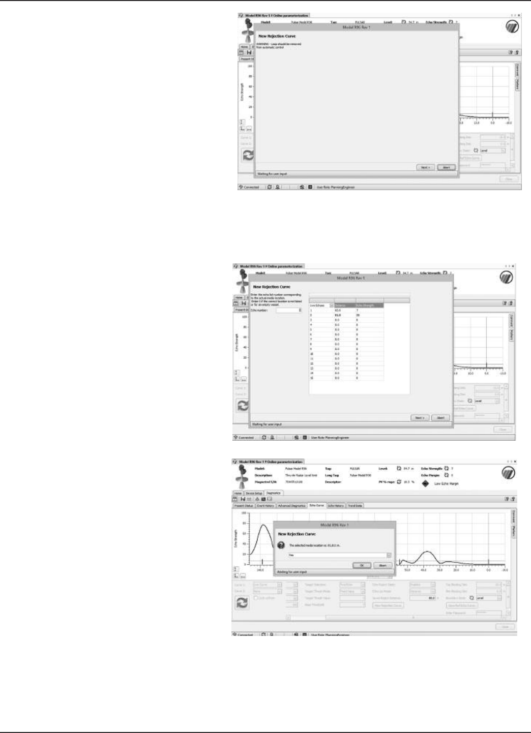
66 58-603 Pulsar®Model R86 Radar Transmitter
Click on NEXT at the loop warning message.
On the next screen, enter the actual location of the level to
be measured and then click on NEXT.
A password window will then appear (unless the password
was previously entered). Enter the password and click OK.
Then the system calculates the curve, and then saves it.
Click OK to confirm.
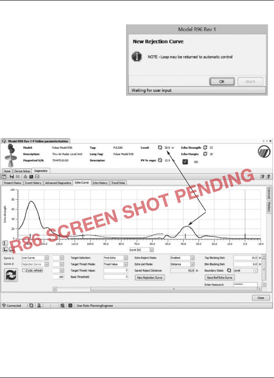
67
58-603 Pulsar®Model R86 Radar Transmitter
A warning screen is shown that the loop can be returned to
automatic control.
At this point the echo rejection curve can be viewed by
selecting Rejection Curve as Curve 2 in the lower left corner
of the Echo Curve screen. The Rejection curve will then be
displayed as shown in the screenshot below.
Actual
Level

68 58-603 Pulsar®Model R86 Radar Transmitter
APPENDIX
Custom Echo Rejection
INTRODUCTION
The Pulsar Model R86 has a unique feature that allows for a user to manually adjust a Standard Echo
Rejection curve. Custom Echo Rejection is a feature intended to allow a user to manually adjust the
curve to account for undesirable waveform features (noise, disturbances, etc.) that may not have been
captured by the initial Standard Echo Rejection curve.
For example, undesirable signals may occur if the original echo rejection curve was taken at a time
when mixing blades were stopped in a particular location If the blades then stop in a different loca-
tion a false echo from the blade could then appear in the live echo curve. Custom Echo Rejection
allows the user to manually modify the Standard Echo Rejection curve in order to ensure that all
“false echoes” are cancelled out of the waveform.
The Custom Echo Rejection curve is offered in addition to the Standard Echo Rejection curve. Once
a Custom Echo Rejection curve has been created, either curve is available for use by the user to reject
unwanted echo echoes. The user has the ability to select which curve (or no curve) will be used for
echo rejection.
Since the local display does not have the ability to concurrently display the live and rejection echo
curves, the manipulation of the echo rejection curve will be done in the DD and DTM only. The abil-
ity to view the two curves graphed together is essential in determining how the rejection curve should
be modified to provide the desired outcome.
The Echo Curve graph will show only one of the two echo rejection curves at a time, with the Custom
Echo curve always shown as Curve 2.
When the Custom Echo Rejection curve is selected for use, the “New Rejection Curve” button will
change to “Modify Rejection Curve”. Clicking on this button will guide a user through modifying an
existing echo in the custom curve, copying an echo from the live curve to the custom rejection curve,
or resetting a Custom Echo Rejection curve back to the original form from which it was taken
(Standard Echo Rejection curve).
OPERATION
BEFORE STARTING: Note that changes to certain parameters cause the Echo Rejection profile to
become invalid. Those parameter changes will invalidate both the Standard and the Custom rejection
curves simultaneously, regardless of which echo rejection curve option is selected at the time. For
example, making any changes to Gain parameters (Dielectric, Turbulence, Foam and Sensitivity) or
Tank Height parameter will invalidate all Echo Rejection Curves whether Standard or Custom.

69
58-603 Pulsar®Model R86 Radar Transmitter
MODIFICATION
The Custom Echo Rejection curve can be modified in three ways:
1. Modify existing Echo
Changing the amplitude or width of an existing echo in the Custom Rejection Curve is one the most
typical uses of this method. For example, it can be used to account for the variations in mixing blade
operation. If mixing blades are stopped when the initial curve was created, the next time the blades
stop they may be in a slightly different position. The new blade position can result in a slightly differ-
ent position of its echo. Echoes from the blade will appear in the echo curve as slightly shifted to the
left or right compared to the echo in the original curve. The amplitude may also be somewhat differ-
ent. In that case, expanding the width of the existing echo, or changing its amplitude would create an
echo rejection curve that encompasses both the original echo and the new echo locations.
2. Add an Echo
This is used to copy an echo from the live curve to the Custom Rejection Curve. This would be done
in the event that a new echo was found in the live curve after the initial echo rejection curve had been
saved.
NOTE: In the case where the level at the time was higher in the tank, saving a new entire echo rejection curve would
result in a lower portion of the rejection curve being lost. Therefore, it is beneficial in that circumstance to
be able to add the echo to the existing custom curve so that the lower portion of the curve is retained.
3. Reset Custom Curve
If the need arises to eliminate changes made during any of the previous modification procedures, Reset
Custom Curve is used to reset the Custom Rejection Curve back to its original values.
PROCEDURES
Changing the amplitude of an existing echo
Modifying an existing echo in the custom rejection echo curve consists of the user identifying the
desired echo and defining the amplitude to be made to that echo. The user starts the Customize
Rejection Curve method in the DTM at Diagnostics/ Echo Curve/
1. Ensure a Standard Echo Rejection has been captured before continuing (Standard Echo Rejection will
appear as red curve on graph)
2. Change “Echo Rejection Type” from “Standard” to “Custom”
3. The “New Rejection Curve” button changes to “Modify Rejection Curve”; press button
4. Choose “Modify Existing Echo”
5.
6.
7. Upon presentation of the Rejection echo list (including the echo amplitudes), along with a display of
the present level, select the desired echo to be modified. (The distance to the echo must be smaller
than the distance to the level echo).
8. Enter the new peak amplitude for the echo. Note that this amplitude can be smaller than the original
amplitude if it is desired to reduce an echo height.

70 58-603 Pulsar®Model R86 Radar Transmitter
Widening an existing echo ADD this as addition to Amplitude so there is one???
Widening an existing echo in the custom rejection echo curve consists of the user identifying the
desired echo and defining the width changes to be made to that echo. The widening process creates
an echo shape in which the left and right side slopes of the original echo remain the same, although
separated, and that has a flat top at the peak amplitude of the original echo.
1. The user starts the Customize Rejection Curve method, then selects “Modify existing Echo” as the
modification option.
2. Upon presentation of the Rejection echo list, along with a display of the present level, select the
desired echo to be modified. (The distance to the echo must be smaller than the distance to the level
echo).
3. The user is presented with the existing locations for where the echo crosses the base threshold.
4. The user enters the new left and right locations for the base crossing threshold points.
Narrowing an existing echo (???Alan checking if we can actually do this)
Narrowing an existing echo in the custom rejection echo curve consists of the user identifying the
desired echo and defining the width changes to be made to that echo.
NOTE: Narrowing an echo can only be performed if the echo has already been widened.
1. The user selects “Modify existing Echo??????????” as the modification option.
2. Upon presentation of the Rejection echo list, along with a display of the present level, the user selects
the desired echo to be modified. The distance to the echo must be smaller than the distance to the
level echo.
3. The user is presented with the existing locations for where the echo crosses the base threshold.
4. The user enters the new left and right locations for the base crossing threshold points.
Reset Custom (rejection) curve
Use Reset Custom curve to erase what has been done to the Custom Rejection to start over.
4.x Tank Profile
Introduction
Non-Contact radar transmitters are typically configured and commissioned with a static liquid level.
Ideally, the installer will generate some level change after commissioning to verify proper operation,
but rarely can one witness a complete fill and empty cycle of the vessel. Therefore, the transmitter
configuration may not initially be optimized for the entire range of operation.
Although previous versions of Magnetrol transmitters contain troubleshooting options for recording
and saving diagnostic information such as Data Log, Event History, and Echo History, none contains
a way for the device to automatically capture pertinent information for an entire fill and empty cycle.
As this complete cycle could take hours, days or even weeks to complete, having this information will
confirm proper operation for a given configuration or can provide precious information about the
transmitter performance at troublesome levels in the tank.
The information is stored in the transmitter, retrieved at a later time and evaluated by a qualified indi-
vidual who will decide the next steps to take.

71
58-603 Pulsar®Model R86 Radar Transmitter
A few items to note:
1. The Tank Profile feature must be manually initiated. It is not an automatic feature.
2. The Tank Profile feature may be manually stopped at any time.
3. Before the feature starts capturing information, the transmitter configuration should be manually
saved. This is not necessary for the operation of the feature but provides useful data for determining
what configuration change may be warranted.
4. Although the ability to set up and run this feature will be available in all user interfaces (HART and
FF LUI, DD and DTM), the results can only be graphically viewed in the corresponding DTM. For
DD-based hosts, there is a DD method that will sequentially display the readings one level at a time.
5. The feature can be set to cover a smaller range than the entire tank. For example, some processes may
only operate in a smaller range.
6. The increments can be set as a percentage of the Start/Stop range (Increment by %) or in
Level/Distance units (Increment by Unit).
7. The information captured at each increment will be:
a. Time
b. Level
c. Distance
d. Echo Strength
e. Echo Margin
f. Loop Current (HART only)
g. Target Threshold
h. Level Ticks
i. BCSM state
8. The saved minimum and maximum Echo Strength and Echo Margin readings can be viewed in a
graph in the Tank Profile menu.
SETUP
The Tank Profile can be initiated in the DTM in the following manner:
1. Use SET CLOCK button to ensure transmitter clock is set properly
2. Choose LIMIT UNITS of “Level” or “ % Range”
a. RECORD INTERVAL and TANK PROFILE units will change accordingly
3. Choose INTERVAL, LIMITS and TIMES applicable to your needs.
4. TANK PROFILE STATUS will display “Off”, “Running” or “Completed”
5. Once computer is used to configure transmitter it does not have to stay connected.
6. Connect computer at later date to download captured data for analysis????????????
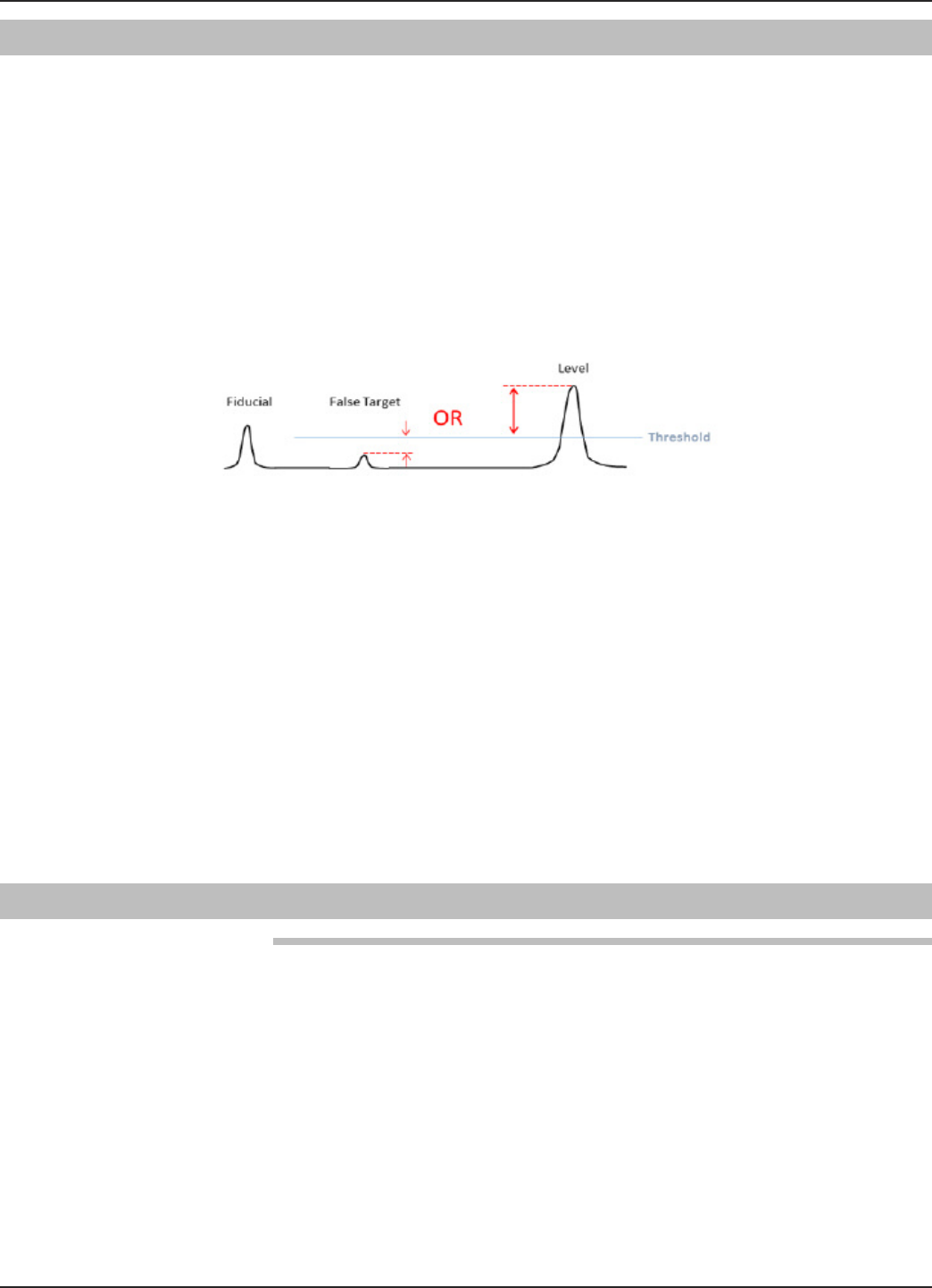
72 58-603 Pulsar®Model R86 Radar Transmitter
4.x Echo Margin
Echo Margin is a unique parameter that, when used along with Echo Strength can be a very useful
troubleshooting tool. Echo Strength is taken from the standard Signal-to-Noise calculation and is
simply defined as:
“The amplitude of the Level echo in Echo Strength units (0-100)”
Echo Margin is defined as:
“A numeric value that is related to the strength of the target peak relative to the Level Threshold or
competing waveform features, i.e. "noise.”
The Echo Margin value (for the typical First Echo mode) is calculated as the difference of the False
target-to-Threshold OR the Level target-to-Threshold whichever is SMALLER.
By reporting the SMALLER value, Echo Margin does a better job of reporting which issue is most
likely to become a problem:
• False Target- if this echo becomes large enough to rise above the Threshold it will be mistakenly
reported as the Level.
• Level Echo- if this echo becomes small enough to fall below the Threshold the transmitter will report
Loss of Echo.
Always examine both Echo Strength and Echo Margin values. Increasing a Gain parameter
(Dielectric, Turbulence, Foam or Sensitivity) will increase the amplitude of all echoes in the radar
scene. If, after increasing a Gain parameter, the Echo Strength increases but the Echo Margin decreas-
es a False Target is reaching closer to the Threshold (see drawing above). If the False Target reaches
above the Threshold it will be detected as a valid Level echo and will be incorrectly reported as Level.
In this case running Echo Rejection will eliminate the False Target and increase the Echo Margin
value. Echo Margin values >20 are a good goal.
4.x Automated Echo Capture
Unattended Echo Capture
One of the ways the Model R86 simplifies an often complex technology like Radar, is to improve the
speed at which a user can turn around a problem and get the device back online. Minimizing down
time is the ultimate goal of any device.
One of the most important tools used to troubleshoot a Radar application or optimize a transmitter
configuration is the echo curve. This graphical representation of a Radar echo speaks volumes to those
trained to interpret them. It is like a snapshot in time of the health of the transmitter. It is actually like
seeing inside of the tank. However, the challenge with echo curves is acquiring them in a timely fash-
ion. Unfortunately, most problems develop when there is a skeleton crew and no one watching this
particulate vessel. By the time an instrument technician can investigate, the alarm has cleared and no
one understands why it occurred or, more importantly, when it will happen again. Since an echo curve
is so important in troubleshooting the device, it is critical to capture the curve at the instant a problem
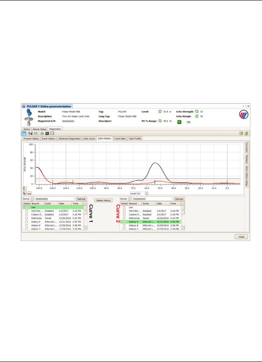
73
58-603 Pulsar®Model R86 Radar Transmitter
occurs. Too often this means connecting a laptop and gathering information AFTER the first signs of
the problem, which is obviously not ideal.
The advanced Pulsar Model R86 design is very effective at addressing this issue. This advanced design
allows the transmitter to automatically capture an Echo Curve based on an Event (such as Loss of
Echo) or Time (using the on-board clock).
It is shipped from the factory so an echo curve is automatically captured based on key Events. The
transmitter has the ability to store a number of echo curves in its on-board memory. These echo curves
can then be downloaded to a laptop running software such as PACTware and reviewed in
Diagnostics/Echo History tab. If necessary, the user can email this information to the factory for
expert assistance in troubleshooting. This enables the problem to be resolved much more quickly, min-
imizing possible down time.
An example of this is shown below.
A number of points should be made in this example:
• Curve 1 is showing the current Live echo
• Curve 2 is showing “History 9”- the 9th echo stored in memory which was automatically captured at
2:45P on 12/31/2016
•This echo capture was triggered by the “Inferred Level” diagnostic

74 58-603 Pulsar®Model R86 Radar Transmitter
SETUP
NOTE: The transmitter is shipped from the factory configured to automatically capture Echo Curves based on
“Events” with ALL Events being enabled.
Automated Echo Capture is configured in the DTM in the following manner:
1. Open DTM to Diagnostics/Echo History
2. Click on “Echo History Setup” tab on right side
3. Enter PASSWORD
4. ECHO HISTORY MODE- choose “Events” (typical)
a. If “Time” is chosen use SET DEVICE CLOCK to ensure correct time.
i. Choose START and STOP times
ii. Minimum RECORD INTERVAL will be offered based on number of EVENTS chosen and
duration based on START/STOP times.
5. EVENTS- choose which Events to trigger the echo capture. Choosing all Events is typical.
All live and captured echoes can then be viewed (and compared) in the ECHO HISTORY tab of the
DTM.
4.x Event History
Although Event History has been included (and found to be very useful) in other Magnetol devices, it
has been improved in the Model R86.
Event History becomes the main repository of all key Diagnostic and Configuration data. It now dis-
plays a history of the 20 most recent diagnostic indicators and configuration changes. For each event,
the time when the event occurred and the duration of the event are shown. The table of history indi-
cators displays the most recent indicator at the top with preceding indicators in descending order.
NOTE: A “+” suffix denotes the event remains active
Key Features:
• 20 lines of Event information
• All Diagnostic and Configuration info
• Now 7 columns of data
• Item #
• Event name
• Date
• Time
• Duration
• Value1
• Value2
Value1 and Value2 entries have various meanings depending on the Event. (A comprehensive explana-
tion of these entries is included in this section.) It is highly recommended to Set Clock (in transmit-
ter) if actual Dates and Times are not shown.
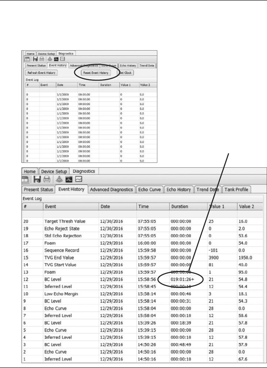
75
58-603 Pulsar®Model R86 Radar Transmitter
Below is a step-by-step procedure used when accessing the Event Hisotry from the DTM:
(Although Event History can be viewed via the Local User Interface, the DTM offers a more complete
view of the information.)
Press “Refresh Event History” upon opening the screen.
A “+” sign indicates
the event is active

76 58-603 Pulsar®Model R86 Radar Transmitter
7 LOW ECHO MARGIN
Value 1 - EM value when captured
Value 2 - Level value when captured
# Event Date Time Duration Value1 Value2
20BC Level 2017-01-18 13:05:21 022:34:12+ 1218.0
19 Echo Reject State 2017-01-15 11:14:01 000:00:00 0 2.0
18 Std. Echo Rejection 2017-01-15 11:10:59 000:00:00 0 24.1
17 Foam 2017-01-15 11:08:39 000:00:00 1 35.0
16 Echo Curve 2017-01-15 09:41:45 000:00:00 2 83.2
15 Echo Lost 2017-01-15 09:41:15 000:87:45 0 83.2
14 Foam 2017-01-15 09:40:13 000:00:00 0 9.0
13 Max. Jump Exceeded 2017-01-12 01:26:41 000:00:49 32 118.5
12 Echo Reject State 2017-01-12 01:25:23 070:02:13 20 27.4
11 Foam 2017-01-12 01:25:23 000:00:00 2 88.0
10 BC Level 2017-01-08 15:51:20 000:17:49 1 33.1
9 Echo Reject State 2017-01-08 15:51:05 000:00:00 0 2.0
8 Echo Curve 2017-01-08 15:32:46 000:00:00 7 29.5
7 Low Echo Margin 2017-01-08 15:32:16 000:00:00 5 29.5
6 BC Level 2017-01-08 15:31:10 028:35:45 01 42.1
Event Value1 Value2
ALL DIAGNOSTIC INDICATORS
(unless otherwise noted below) 0 = No value (unused) Level value when capturead
Analog Board Error Error Code 0 = No value (unused)
Analog Output Error Measured current Expected current
Boundary Condition State (BCS)
changes,
Echo Lost and Inferred Level
XX- 2-digit value
1st digit = Beginning state
2nd digit = Ending state
Based on following codes:
0 = Initialization
1 = Level (normal)
2 = Empty
3 = Full
4 = Echo Missing
5 = Echo Lost
6 = No Fiducial
7 = Restart
Level value when captured
Echo Curve (automated capture) Capture based on:
12 - Too Many Echoes
14 - Echo Lost
17 - High Volume Alarm
18 - High Flow Alarm
28 - Inferred Level
33 - Max Jump Exceeded
34 - Low Echo Margin
Level value when captured
SECTION TITLE???

77
58-603 Pulsar®Model R86 Radar Transmitter
Echo Lost See BCS changes
High Electrical Temp 0 = No value (unused) Temp when activated
High Surface Velocity Value when activated Level value when captured
Inferred Level See BCS changes
Low Echo Margin Value when activated Level value when captured
Low Electrical Temp 0 = No value (unused) Temp when activated
Low Supply Voltage Extrapolated terminal
Lower voltage
Extrapolated terminal
Upper voltage
Max. Jump Exceeded Beginning Level value Ending Level value
Reject Curve Invalid 0 = No value (unused) 0 = No value (unused)
Reset Max/Min Temperatures Max Temp before reset Min Temp before reset
Sweep Time Error DAC setting Sweep width
Too Many Echoes Number of Echoes found Level value when captured
Event Value1 Value2
# Run Average Old value New Value
4mA (LRV) Old value New value
20mA (URV) Old value New value
Base Threshold Old value New value
Bottom Blocking Distance Old value New value
Custom Echo Rejection 0 = No value (unused) Level value when captured
Dielectric 0 = 1.4–1.7
1 = 1.7–3.0
2 = 3.0–10
3 = >10
Corresponding Echo Strength
Echo Rejection Type
2 = Standard Echo Rejection
3 = Custom Echo Rejection
Old value New Value
Echo Reject State Old Value
0 = Off
1 = Disabled
2 = Enabled
New Value
FME Distance Threshold Old value New Value
Foam 0 = None
1 = Light
2 = Medium
3 = Heavy
Corresponding Echo Strength
HART Poll address Old value New value
Level Trim Old value New value
Max Level Jump Old value New value
Max Surface Velocity Old value New value
Passwords (Date/Time only) 0 = No value (unused) 0 = No value (unused)
Configuration Parameters

78 58-603 Pulsar®Model R86 Radar Transmitter
Event Value1 Value2
Rate of Change Old value
0 = <5 in/min (<130mm/min)
1 = 5–20 in/min (130-500mm/min)
2 = 20–60 in/min (500–1500mm/min)
3 = >60 in/min (>1500mm/min)
New value
Sensitivity Value Corresponding Echo Strength
Standard Echo Rejection 0 = No value (unused) Level value when captured
Stillwell ID Old value New value
Tank Height Old value New value
Target Selection Old value
1 = First Echo
2 = Largest Echo
3 = First Moving Echo
New value
Target Threshold Mode Old value
1 = Automatic
2= Fixed
New value
Target Threshold Value Old value
Automatic = % of Peak Max
Fixed = Value in Eng. Units
New value
Top Blocking Distance Old value New value
Turbulence 0 = None
1 = Light
2 = Medium
3 = Heavy
Corresponding Echo Strength
TVG End Location Old value New value
TVG End Value Old value New value
TVG Start Location Old value New value
TVG Start Value Old value New value
Complete Listing of Diagnostic Indicators including Analog Board Errors
Error Code Diagnostic Explanation
0 OK
1 Software Error Instruction execution traversed an incorrect path
2 RAM Error run-time volatile memory test failed
3 ADC Error Run-time analog-to-digital converter test failed
4 EEPROM Error Unrecoverable checksum error in non-volatile memory
5 Analog Board Error Delay-locked loop malfunction
6 Analog Output Error Measured loop current differs from commanded value
7 Spare
8 Default Params All parameters reset to default values
9 Spare
10 Sweep Time Error Analog Board sweep time error
11 Spare
Configuration Parameters

79
58-603 Pulsar®Model R86 Radar Transmitter
Complete Listing of Diagnostic Indicators including Analog Board Errors (continued)
Error Code Diagnostic Explanation
12Too Many Echoes Excessive number of waveform features are possible echoes
13 Safe Zone Alarm Level is above Safe Zone end
14 No Echoes Echo from upper surface missing for longer than Echo Loss Delay
15 Spare
16 Config Conflict Configuration conflict caused by incompatible parameter selections
17 High Volume Error Calculated Volume exceeds maximum for vessel or custom table
18 High Flow Error Calculated Flow exceeds maximum for flume or custom table
19 Spare
20 Initializing System warming up, distance measurement not yet valid
21 Config Changed A parameter(s) has recently been modified from the User Interface
22 Spare
23 High Electrical Temp Present electronics temperature above maximum
24 Low Electric Temp Present electronics temperature below minimum
25 Calibration Required Distance calibration parameters are at default values
26 Echo Rejection Invalid Previously stored Echo Rejection Curve invalidated by parameter change
27 Spare
28 Inferred Level
Typically this is caused when the Level target has been lost or has
entered either the Top or Bottom Blocking Distance zones. If in the Top
or Bottom Blocking Distance zones the transmitter will read Full (Top) or
Empty (Bottom). The Level reading (and mA value) will never be higher
than the value related to the Top Blocking Distance or lower than the
value related to the Bottom Blocking Distance.
29 Adjust Analog Output Loop trim parameters are at default values
30 Totalizer Data Lost Totalizer data has been lost, restarted from zero
31 Low Supply Voltage Power supply voltage inadequate to prevent brownout or reset
32 Spare
33 Max Jump Exceeded Transmitter has jumped to an echo that exceeds the Max Distance Jump
value from the previous echo.
34 Marginal Echo Signal Margin is less than allowable minimum
35 High Surface Velocity The measured Surface Velocity is greater than the Max Surface Velocity
value derived from the Rate of Change parameter.
36 Spare
37 Seq Record Instruction execution traversed a correct but unexpected path (formerly
System Warning)
38 Unknown Unknown event id received
39 No Event Used when reading history from host
70 Device Variable Alert Device variable alert active in Extended Device Status byte
71 Echo History Time Used for denoting time-based echo history save

BULLETIN: 58-603.PRE1
EFFECTIVE: April 2017
Service Policy
Owners of MAGNETROL may request the return of a
control or any part of a control for complete rebuilding or
replacement. They will be rebuilt or replaced promptly.
Controls returned under our service policy must be
returned by Prepaid transportation. MAGNETROL will
repair or replace the control at no cost to the purchaser
(or owner) other than transportation if:
1. Returned within the warranty period; and
2. The factory inspection finds the cause of the claim to
be covered under the warranty.
If the trouble is the result of conditions beyond our con-
trol; or, is NOT covered by the warranty, there will be
charges for labor and the parts required to rebuild or
replace the equipment.
In some cases it may be expedient to ship replacement
parts; or, in extreme cases a complete new control, to
replace the original equipment before it is returned. If this
is desired, notify the factory of both the model and serial
numbers of the control to be replaced. In such cases, cred-
it for the materials returned will be determined on the
basis of the applicability of our warranty.
No claims for misapplication, labor, direct or consequen-
tial damage will be allowed.
Return Material Procedure
So that we may efficiently process any materials that are
returned, it is essential that a “Return Material
Authorization” (RMA) number be obtained from the fac-
tory, prior to the material’s return. This is available through
a MAGNETROL local representative or by contacting the
factory. Please supply the following information:
1. Company Name
2. Description of Material
3. Serial Number
4. Reason for Return
5. Application
Any unit that was used in a process must be properly
cleaned in accordance with OSHA standards, before it is
returned to the factory.
A Material Safety Data Sheet (MSDS) must accompany
material that was used in any media.
All shipments returned to the factory must be by prepaid
transportation.
All replacements will be shipped F.O.B. factory.
ASSURED QUALITY & SERVICE COST LESS
Magnetrol, Magnetrol logotype and Pulsar are registered trademarks of Magnetrol International, Incorporated.
Viton® and Kalrez® are registered trademarks of DuPont Performance Elastomers.
HART® is a registered trademark of the HART Communication Foundation
PACTware™ is trademark of PACTware Consortium
CSA logotype is a registered trademark of Canadian Standards Association
Halar® is a registered trademark of Allied Chemical Corp.
Hastelloy® is a registered trademark of Haynes International, Inc.
Monel® is a registered trademark of Special Metals Corporation (Formerly Inco Alloys International)
KYNAR® is a registered trademark of Pennsalt Chemicals Corp.
Tri-Clover® is a registered trademark of Alfa Laval, Inc.
705 Enterprise Street • Aurora, Illinois 60504-8149 • 630-969-4000
info@magnetrol.com • www.magnetrol.com
Copyright © 2017 Magnetrol International, Incorporated
PULSAR Pulse Burst Radar transmitters may be protected by one or more of the following U.S. Patent Nos.:
US 6,062,095; US 6,980,174; US 7,102,584; US 7,106,248; US 7,271,646