Magtek orporated 21165046 Intellistripe 65 Contactless Cad Reader, 21165046 User Manual
Magtek Incorporated Intellistripe 65 Contactless Cad Reader, 21165046 Users Manual
Users Manual


ii
Copyright© 2000-2007
MagTek®, Inc.
Printed in the United States of America
Information in this document is subject to change without notice. No part of this document may be
reproduced or transmitted in any form or by any means, electronic or mechanical, for any purpose,
without the express written permission of MagTek, Inc.
MagTek is a registered trademark of MagTek, Inc.
IntelliStripe® is a registered trademark of MagTek, Inc.
Torx® is a registered trademark of Textron, Inc.
REVISIONS
Rev Number Date Notes
1 8 May 2006 Initial Release
2 13 Feb 2007 Added RoHS Statement. Updated to show OTI contactless module
3 26 Mar 2007 Clarified FCC statement; updated operating temperature range
iii
LIMITED WARRANTY
MagTek warrants that the products sold to Reseller pursuant to this Agreement will perform in accordance with
MagTek’s published specifications. This warranty shall be provided only for a period of one year from the date of the
shipment of the product from MagTek (the “Warranty Period”). This warranty shall apply only to the original
purchaser unless the buyer is authorized by MagTek to resell the products, in which event, this warranty shall apply
only to the first repurchase.
During the Warranty Period, should this product fail to conform to MagTek’s specifications, MagTek will, at its
option, repair or replace this product at no additional charge except as set forth below. Repair parts and replacement
products will be furnished on an exchange basis and will be either reconditioned or new. All replaced parts and
products become the property of MagTek. This limited warranty does not include service to repair damage to the
product resulting from accident, disaster, unreasonable use, misuse, abuse, customer’s negligence, Reseller’s
negligence, or non-MagTek modification of the product. MagTek reserves the right to examine the alleged defective
goods to determine whether the warranty is applicable.
Without limiting the generality of the foregoing, MagTek specifically disclaims any liability or warranty for goods
resold in other than MagTek’s original packages, and for goods modified, altered, or treated by customers.
Service may be obtained by delivering the product during the warranty period to MagTek (20801 S. Annalee Ave.,
Carson, CA 90746). If this product is delivered by mail or by an equivalent shipping carrier, the customer agrees to
insure the product or assume the risk of loss or damage in transit, to prepay shipping charges to the warranty service
location and to use the original shipping container or equivalent. MagTek will return the product, prepaid, via a three
(3) day shipping service. A Return Material Authorization (RMA) number must accompany all returns.
MAGTEK MAKES NO OTHER WARRANTY, EXPRESS OR IMPLIED, AND MAGTEK DISCLAIMS ANY
WARRANTY OF ANY OTHER KIND, INCLUDING ANY WARRANTY OF MERCHANTABILITY OR FITNESS
FOR A PARTICULAR PURPOSE.
EACH PURCHASER UNDERSTANDS THAT THE MAGTEK PRODUCT IS OFFERED AS IS. IF THIS
PRODUCT DOES NOT CONFORM TO MAGTEK’S SPECIFICATIONS, THE SOLE REMEDY SHALL BE
REPAIR OR REPLACEMENT AS PROVIDED ABOVE. MAGTEK’S LIABILITY, IF ANY, TO RESELLER OR
TO RESELLER’S CUSTOMERS, SHALL IN NO EVENT EXCEED THE TOTAL AMOUNT PAID TO MAGTEK
BY RESELLER UNDER THIS AGREEMENT. IN NO EVENT WILL MAGTEK BE LIABLE TO THE RESELLER
OR THE RESELLER’S CUSTOMER FOR ANY DAMAGES, INCLUDING ANY LOST PROFITS, LOST
SAVINGS OR OTHER INCIDENTAL OR CONSEQUENTIAL DAMAGES ARISING OUT OF THE USE OF OR
INABILITY TO USE SUCH PRODUCT, EVEN IF MAGTEK HAS BEEN ADVISED OF THE POSSIBILITY OF
SUCH DAMAGES, OR FOR ANY CLAIM BY ANY OTHER PARTY.
LIMITATION ON LIABILITY
EXCEPT AS PROVIDED IN THE SECTIONS RELATING TO MAGTEK’S LIMITED WARRANTY, MAGTEK’S
LIABILITY UNDER THIS AGREEMENT IS LIMITED TO THE CONTRACT PRICE OF THE PRODUCTS.
MAGTEK MAKES NO OTHER WARRANTIES WITH RESPECT TO THE PRODUCTS, EXPRESSED OR
IMPLIED, EXCEPT AS MAY BE STATED IN THIS AGREEMENT, AND MAGTEK DISCLAIMS ANY IMPLIED
WARRANTY, INCLUDING WITHOUT LIMITATION ANY IMPLIED WARRANTY OF MERCHANTABILITY
OR FITNESS FOR A PARTICULAR PURPOSE.
MAGTEK SHALL NOT BE LIABLE FOR CONTINGENT, INCIDENTAL, OR CONSEQUENTIAL DAMAGES
TO PERSONS OR PROPERTY. MAGTEK FURTHER LIMITS ITS LIABILITY OF ANY KIND WITH RESPECT
TO THE PRODUCTS, INCLUDING ANY NEGLIGENCE ON ITS PART, TO THE CONTRACT PRICE FOR THE
GOODS.
MAGTEK’S SOLE LIABILITY AND BUYER’S EXCLUSIVE REMEDIES ARE STATED IN THIS SECTION
AND IN THE SECTION RELATING TO MAGTEK’S LIMITED WARRANTY.

FCC WARNING STATEMENT
This equipment has been tested and found to comply with the limits for Class B digital device, pursuant to Part 15
of FCC Rules. These limits are designed to provide reasonable protection against harmful interference when the
equipment is operated in a residential environment. This equipment generates, uses, and can radiate radio
frequency energy and, if not installed and used in accordance with the instruction manual, may cause harmful
interference to radio communications. However, there is no guarantee that interference will not occur in a
particular installation. Changes or modifications not expressly approved by MagTek could void the user's
authority to operate the equipment.
FCC COMPLIANCE STATEMENT
This device complies with Part 15 of the FCC Rules. Operation of this device is subject to the following two
conditions: (1) This device may not cause harmful interference; and (2) this device must accept any interference
received, including interference that may cause undesired operation.
CANADIAN DOC STATEMENT
This digital apparatus does not exceed the Class B limits for radio noise for digital apparatus set out in the Radio
Interference Regulations of the Canadian Department of Communications.
Le présent appareil numérique n’émet pas de bruits radioélectriques dépassant les limites applicables aux
appareils numériques de las classe B prescrites dans le Réglement sur le brouillage radioélectrique édicté par les
ministère des Communications du Canada.
CE STANDARDS
Testing for compliance to CE was performed by an independent laboratory. The unit under test was found
compliant to Class B.
UL/CSA
This product is recognized per Underwriter Laboratories and Canadian Underwriter Laboratories 1950.
RoHS STATEMENT
When ordered as RoHS compliant, this product meets the Electrical and Electronic Equipment (EEE) Reduction
of Hazardous Substances (RoHS) European Directive 2002/95/EC. The marking is clearly recognizable, either as
written words like “Pb-free” or “lead-free”, or as another clear symbol ( ).
EMVCo APPROVAL STATEMENT
EMVCo approval of the interface module (IFM) contained in this Terminal shall mean only that the IFM has been
tested in accordance with the EMV Level 1 Specifications, Version 4.1, as of the date of testing. EMVCo
approval does not under any circumstances include any endorsement or warranty regarding the completeness of
the approval process or the functionality, quality or performance of any particular product or service. EMVCo
does not warrant any products or services provided by third parties. EMVCo approval does not under any
circumstances include or imply any product warranties from EMVCo, including, without limitation, any implied
warranties of merchantability, fitness for purpose, or non-infringement, all of which are expressly disclaimed
by EMVCo. All rights and remedies regarding products and services, which have received EMVCo approval,
shall be provided by the party providing such products or services, and not by EMVCo.
iv
v
TABLE OF CONTENTS
SECTION 1. FEATURES AND SPECIFICATIONS..................................................................................... 1
CONFIGURATIONS ................................................................................................................................. 1
ACCESSORIES........................................................................................................................................ 2
RELATED DOCUMENTS......................................................................................................................... 2
STANDARD FEATURES.......................................................................................................................... 3
OPTIONS.................................................................................................................................................. 3
SMART CARD INTERFACE..................................................................................................................... 3
MAGNETIC STRIPE READER................................................................................................................. 4
LATCH ...................................................................................................................................................... 4
ON BOARD SAM INTERFACE ................................................................................................................ 4
SENSING SWITCHES.............................................................................................................................. 4
Card Present Switch............................................................................................................................. 4
Card Seated Switch.............................................................................................................................. 4
Card Latch Switch ................................................................................................................................4
TEST LED................................................................................................................................................. 5
FLASH UPGRADABLE............................................................................................................................. 5
RS-232 INTERFACE ................................................................................................................................5
USB INTERFACE..................................................................................................................................... 5
SPECIFICATIONS.................................................................................................................................... 5
SECTION 2. INSTALLATION...................................................................................................................... 7
BEZELS .................................................................................................................................................... 7
International Plastic Bezel.................................................................................................................... 7
International Metal Bezel...................................................................................................................... 7
North American Plastic Bezel............................................................................................................... 7
MECHANICAL MOUNTING AND BEZELS.............................................................................................. 7
Front Flange ......................................................................................................................................... 8
Side Mounting Studs ............................................................................................................................ 8
Side Mounting Holes ............................................................................................................................ 8
ELECTRICAL CONNECTIONS.............................................................................................................. 10
Connectors ......................................................................................................................................... 10
Host Connector - RS-232................................................................................................................... 10
Host Connector - USB........................................................................................................................ 10
Power-Fail Capacitor Connector ........................................................................................................ 10
Contactless Installation ...................................................................................................................... 11
Antenna Installation............................................................................................................................ 13
Accessing SAM Module ..................................................................................................................... 15
RS-232 Cable..................................................................................................................................... 15
USB Cable.......................................................................................................................................... 16
Power Supply ..................................................................................................................................... 16
APPENDIX A. OPTIONS........................................................................................................................... 19
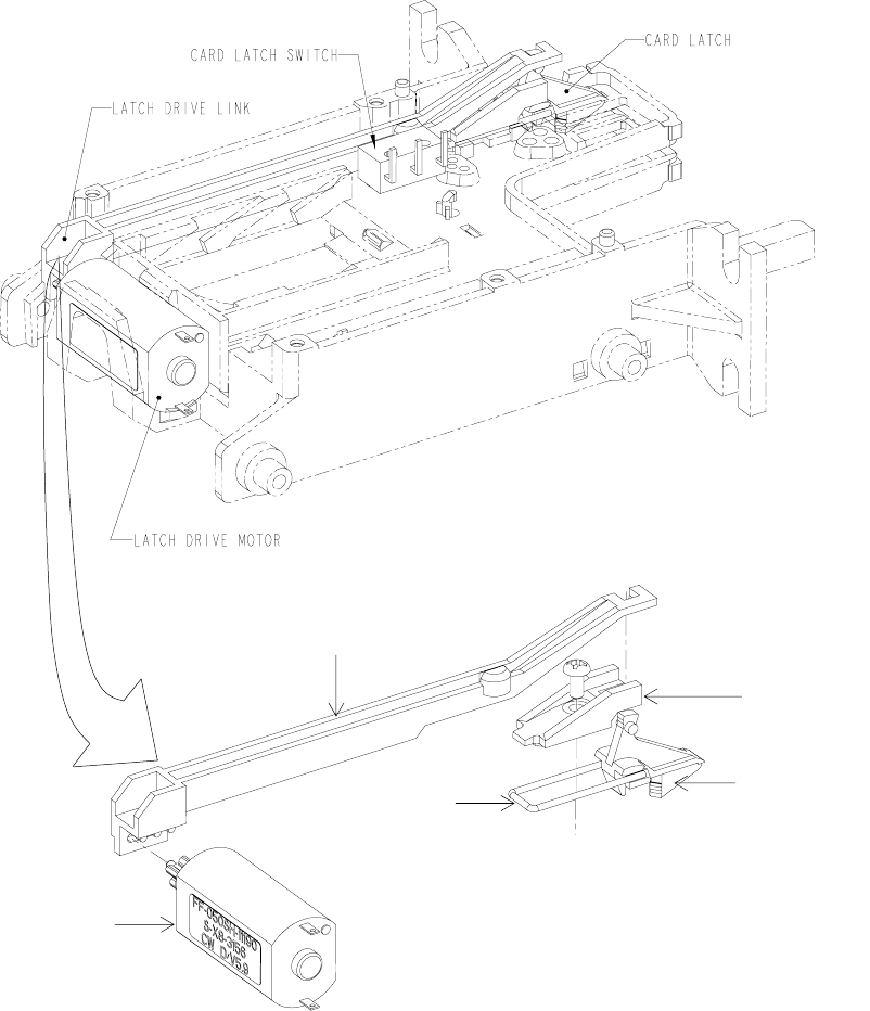
CARD LATCH OPTION.......................................................................................................................... 19
POWER-FAIL LATCH RELEASE OPTION............................................................................................ 20
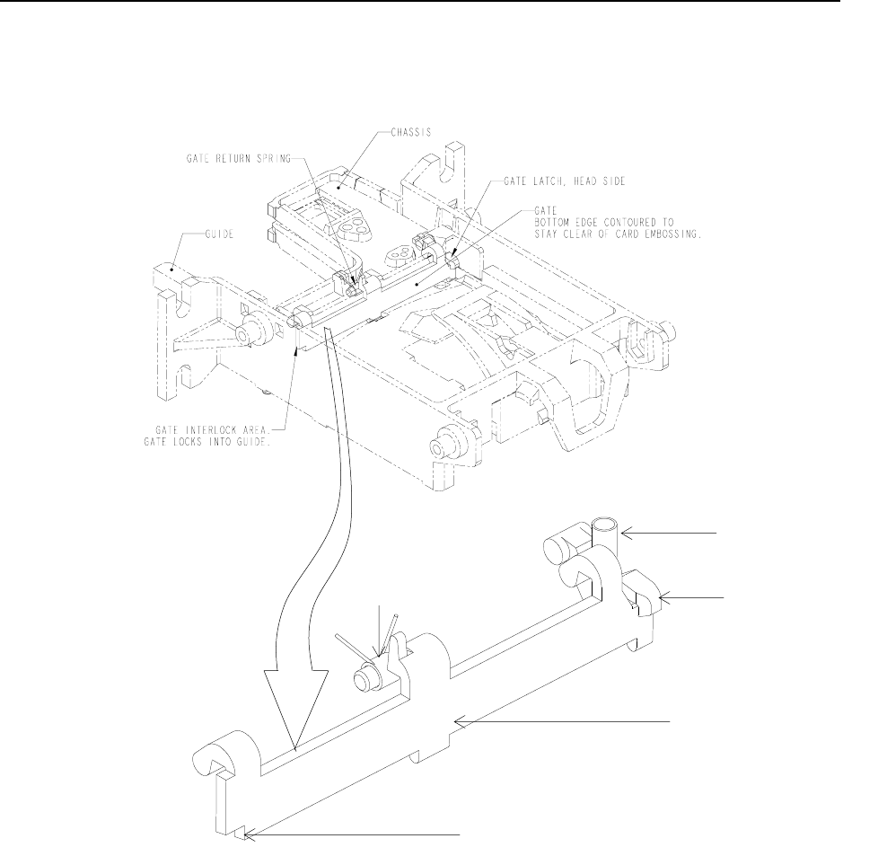
GATE OPTION ....................................................................................................................................... 21
APPENDIX B. BEZEL CONFIGURATION AND MOUNTING .................................................................. 23
INTERNATIONAL PLASTIC BEZEL MOUNTING.................................................................................. 23
INTERNATIONAL METAL BEZEL MOUNTING..................................................................................... 25
Compatibility....................................................................................................................................... 25
NORTH AMERICAN PLASTIC BEZEL MOUNTING.............................................................................. 27
FIGURES and TABLES
Figure 1-1. IntelliStripe 65, Front View ------------------------------------------------------------------------------------viii
Table 1-1. Specifications--------------------------------------------------------------------------------------------------------6
Figure 2-1. Chassis Mounting Features-------------------------------------------------------------------------------------8
Figure 2-2. Dimensions For Mounting ---------------------------------------------------------------------------------------9
Figure 2-3. Power and Communication Connections------------------------------------------------------------------10
Figure 2-4. Fully Equipped Contactless Reader with Antenna in Bezel-------------------------------------------11
Figure 2-5. Installing Contactless Module on Contactless Ready Model -----------------------------------------12
Figure 2-6. Contactless Module Installed --------------------------------------------------------------------------------- 13
Figure 2-7. Using External Antenna with LEDs (Ribbon Cable)-----------------------------------------------------14
Figure 2-8. Using External Antenna without LEDs (Coax Cable) ---------------------------------------------------14
Figure 2-9. Removing Contactless Module to Access SAM Socket------------------------------------------------15
Figure 2-10. RS-232 Cable---------------------------------------------------------------------------------------------------16
Table 2-1. Pin List for RS-232 IntelliStripe 65 Cable-------------------------------------------------------------------16
Figure 2-11. Power Supply--------------------------------------------------------------------------------------------------- 17
Figure A-1. Card Latch Assembly ------------------------------------------------------------------------------------------19
Figure A-2. Latch Release Capacitor --------------------------------------------------------------------------------------20
Figure A-3. Gate Assembly---------------------------------------------------------------------------------------------------21
Figure B-1. Flanges for International Bezel Mounting ----------------------------------------------------------------- 23
Figure B-2. International Plastic Bezel Mounting -----------------------------------------------------------------------24
Table B1. Examples of Configurations Compatible with the Metal Bezel----------------------------------------- 25
Table B2. Examples of Configurations Not Compatible with the Metal Bezel -----------------------------------25
Figure B-3. International Metal Bezel Mounting-------------------------------------------------------------------------26
Figure B-4. North American Plastic Bezel Mounting -------------------------------------------------------------------28
Figure B-5. Small Cutout Bezel (1)-----------------------------------------------------------------------------------------29
Figure B-6. Small Cutout Bezel (2)-----------------------------------------------------------------------------------------30
Figure B-7. Small Cutout Bezel (3)-----------------------------------------------------------------------------------------31
Figure B-8. Small Cutout Bezel (4)-----------------------------------------------------------------------------------------32
Figure B-9. Head-Side Bezel Bracket -------------------------------------------------------------------------------------33
Figure B-10. North American Plastic Bezel with LED Cutout (1)----------------------------------------------------34
Figure B-11. North American Plastic Bezel with LED Cutout (2)----------------------------------------------------35
Figure B-12. North American Plastic Bezel with LED Cutout (3)----------------------------------------------------36
vi
vii
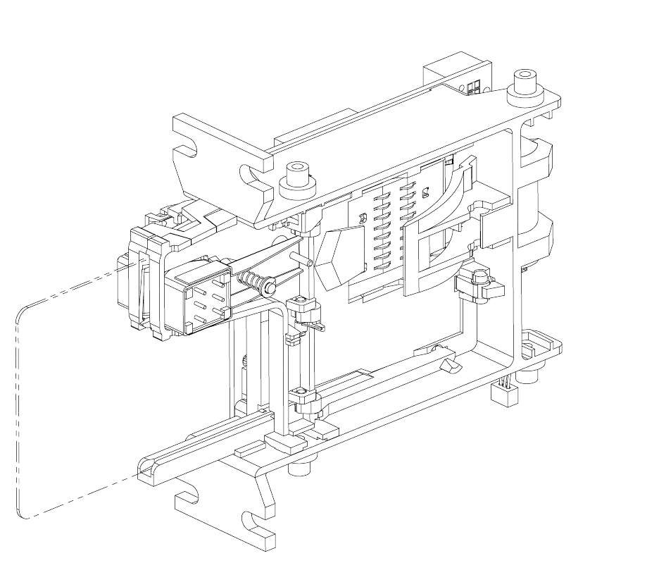
Figure 1-1. IntelliStripe 65, Front View
viii
1
•
•
•
•
•
•
•
•
•
•
•
•
SECTION 1. FEATURES AND SPECIFICATIONS
The IntelliStripe 65™ Insertion Reader, shown in Figure 1-1, performs the following major
functions:
Reads magnetic stripe cards
Communicates with ISO smart cards and many popular memory cards
Supports one on-board SAM (Security Access Module)
Includes an integrated USB interface
Optionally supports Contactless Smart Card communication
The Reader communicates to a host using an RS-232 or USB interface with a defined protocol
and command set. The 3-track Reader has an industry standard mechanical footprint. The
IntelliStripe 65 is designed for self-service applications such as pay telephones, vending
machines, kiosks, and fuel pumps.
CONFIGURATIONS
Unless otherwise specified below, all of the IntelliStripe 65 readers include the following
capabilities:
USB and RS-232 interface
Smart Card connector with 8-contacts
Single SAM socket
Security Gate
Card retention latch with power fail release
Single 3-track head
Bezel with built-in red/green LED
See Appendix A for a description of the options. Part numbers for the basic configurations are
shown in the following table.

IntelliStripe 65, USB/RS-232 Insertion Reader
2
Part
Number Description
21165042 North American Plastic Bezel
21165043 No SAM socket; No security gate; North American Plastic Bezel
21165044 Contactless smart card ready*; International Plastic Bezel
21165046 Same as 21165044 but with Contactless smart card module and antenna installed
21165047 No SAM socket; Contactless smart card ready*; no bezel (front and side mounting
configuration—suitable for metal bezel)
21165048 International Plastic Bezel
21165051 No latch (but motor is supplied for tamper protection); no bezel (front and side mounting
configuration—suitable for metal bezel)
21165052 No gate; no latch, no bezel (front and side mounting configuration—suitable for metal bezel)
21165053 No bezel (front and side mounting configuration—suitable for metal bezel)
21165056 Single 3-track head with ground lug; North American Plastic Bezel
21165058 Contactless smart card ready*; North American Plastic Bezel
* Contactless module, antenna and cable must be ordered separately
ACCESSORIES
Other part numbers that may be shipped with the unit include the following:
Part
Number Description
16051408 RS232 / Power cable − 6 foot, IntelliStripe 65 host port to 9-pin D female RS232 and 2.5mm
power jack
16051430 USB-A to USB mini-B cable (white)
16051433 USB-A to USB mini-B cable (gray)
30037472 Demo Software, IntelliStripe Picture Demo (CD)
30037473 MagTek MCP Drivers (CD)
51300004 OTI Contactless communication module (mounts on “Contactless Ready” models
51300005 OTI Contactless antenna (must be mounted away from IntelliStripe 65 bezel)
51300006 OTI coax antenna cable – 30cm (does not support LEDs)
51300007 OTI ribbon antenna cable – 19cm (supports LEDs)
64300080 Power Supply – Auto-ranging 100V-250V, regulated, 12VDC, 2.5mm plug. Requires adapter
to mate with power outlet; use Adapter/Power Cord (P/N 71100001) for North American
applications.
71100001 Power Outlet Adapter/Cord for North American applications (used with part number
64300080)
99510015 Demo Software, IntelliStripe Picture Demo (Web – ref www.magtek.com)
99510016 MagTek MCP Drivers (Web – ref www.magtek.com)
RELATED DOCUMENTS
This document (P/N 99875339) is from a hardware perspective only. Other MagTek documents
that cover the command set, communications protocol, and API (Application Program Interface)
are as follows:

Section 1. Features and Specifications
3
Part Number Description
99875161 IntelliStripe 65, Command Reference Manual
99875163 MCP, Serial Transport Protocol Reference Manual
99875164 MagTek Communication Protocol, Driver Reference Manual
ISO Documents: 7810, 7811, 7816 are available from ANSI at:
Phone: 212-642-4900 or www.ansi.org
STANDARD FEATURES
Standard features of the IntelliStripe 65 are as follows:
•
•
•
•
•
•
•
•
•
•
•
•
•
•
Multiple bezel styles allow for optimized mounting and integration
Rugged–High impact plastic with read head attached to beam mount
Vandal Resistant–Open chassis design provides superior debris clearing; half-card drop-
out allows half-size credit cards and coins to be cleared from insert channel
On board SAM (Security Access Module)
RS232 and USB interfaces
On board intelligence for transporting large blocks of data using a defined protocol and
command set
Test LED
Program Flash upgradeable
OPTIONS
Any of these options may be selected:
Smart Card Contacts (8) for reading ISO contact locations
Front Card Gate prevents coins, dust, moisture, and debris, from entering the unit–opens
only when ISO-size card enters the unit
Card Latch physically latches the card inside the Reader ensuring optimum conditions for
a smart card interface session
Power-Fail Latch Release Mechanism–In case of a power failure, the latch releases the
card automatically (requires external capacitor)
On board Contactless Smart Card support
Drivers available for all Windows Operating System platforms
SMART CARD INTERFACE
The Reader supports ISO7816 T=0 and T=1 cards not requiring VPP, with a speed range of 9600
bps to 115200 bps. It also supports a variety of common memory card types. See
IntelliStripe 65 Command Reference Manual (P/N 99875161) for more details.

IntelliStripe 65, USB/RS-232 Insertion Reader
4
MAGNETIC STRIPE READER
The Reader can read up to three tracks of magnetic stripe card data. The Mag-stripe can be
configured to support all popular track combinations. See IntelliStripe 65 Command Reference
Manual (P/N 99875161) for more details.
LATCH
The Reader contains a latch that can be used to prevent the user from withdrawing the card
prematurely. See IntelliStripe 65 Command Reference Manual (P/N 99875161) for more details.
The power fail unlatch option disengages the latch during a power failure. This option is
triggered when the power to the reader fails. An external backup capacitor is required for this
option to function. This capacitor can be connected to the reader through a header on the board.
ON BOARD SAM INTERFACE
The Reader provides a socket for one on board SAM. The SAM complies to ISO 7816-3 (1997)
electrical requirements and do not require VPP. T=0 and T=1 are fully supported with a speed
range from 9600 bps to 115200 bps. See IntelliStripe 65 Command Reference Manual (P/N
99875161) for more details.
SENSING SWITCHES
The Reader emulates sensing switches for card present and card latch. A physical sensor is
provided to indicate that the card is seated in the reader and ready for smart card communication.
Card Present Switch
See IntelliStripe 65 Command Reference Manual (P/N 99875161) for more details.
Card Seated Switch
A snap-action switch is operated when a card is fully inserted into the Reader (card is at the fully
rearward position). See IntelliStripe 65 Command Reference Manual (P/N 99875161) for more
details.
Card Latch Switch
See IntelliStripe 65 Command Reference Manual (P/N 99875161) for more details.

Section 1. Features and Specifications
5
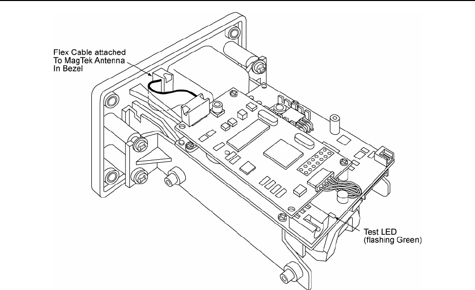
TEST LED
The Test LED is shown in Section 2, Figure 2-4. When the unit is powered up, the Test LED
will blink green. This indicates that the unit is in its standard operating mode.
FLASH UPGRADABLE
The unit’s firmware is in-system Flash Upgradeable. This allows the unit to be upgraded to new
smart card specifications.
RS-232 INTERFACE
The device can communicate to the host through an RS-232 interface. Once the host
communicates to the device on this interface the device will no longer be able to communicate
on any other interface until it is power cycled or reset. The device uses 8 data bits, 1 stop bit,
even parity. The device can automatically sync to baud rates 9600, 14400, 19200, 28800, 38400,
57600 and 115200. See MCP Driver Reference Manual (P/N 99875164), MCP Serial Transport
Protocol Reference Manual (P/N 99875163) and IntelliStripe 65 Command Reference Manual
(P/N 99875161) for more details.
USB INTERFACE
The device can communicate to the host through a USB interface. Once the host communicates
to the device on this interface the device will no longer be able to communicate on any other
interface until it is power cycled or reset. The device uses vendor identifier 0801 (hex) and
product identifier 000A (hex). The device contains a manufacturer string descriptor with a value
of “MagTek”. The device contains a product string descriptor with a value of “IntelliStripe 65”.
The device contains a programmable serial number string descriptor. The device does not get its
power from the USB port; it needs to be self powered. When using the USB port, power must be
applied directly to the PCB via the power connector or the host connector. See MCP Driver
Reference Manual (P/N 99875164), MCP Serial Transport Protocol Reference Manual (P/N
99875163) and IntelliStripe 65 Command Reference Manual (P/N 99875161) for more details.
SPECIFICATIONS
Specifications for the Reader are listed in Table 1-1.

IntelliStripe 65, USB/RS-232 Insertion Reader
6
Table 1-1. Specifications
DATA FORMAT SPECIFICATION
Reader Configuration
Mag-Stripe Functions
Track 1,2,3 only
Smartcard Functions
Data Format Specification*
ISO/AAMVA/ JIS formats
ISO 7810, 7811, JIS x 6302 Type 2
ISO 7816 T=0 and T=1 protocols, many popular memory cards
EMVCo Level 1 Approval
* ISO (International Standards Organization), AAMVA, (American Association of Motor Vehicle
Administrators), JIS (Japanese Industrial Standard)
OPERATIONAL
Card Speed 3 IPS (7,62 cm/sec) to 50 IPS (127, cm/sec)
Recording Method Two-frequency coherent phase (F2F)
MTBF Head: 1,000,000 passes (500,000 Insertion Cycles)
SC contacts: 1,000,000 insertions
ELECTRICAL
Input Voltage
Current
12.0VDC ± 5%
500mA max, (750mA max with contactless smartcard option)
50mA typical, (230mA typical with contactless smartcard option)
MECHANICAL
Chassis Mounting Options
Front Flange See Section 2, Figure 2-1
Side Mounting Studs See Section 2, Figure 2-2
Side Mounting Holes See Section 2, Figure 2-2
Dimensions (Core Chassis)
Overall Length
Mounting Depth
Height
Width
4.70” (119,4mm)
3.80” (96,5mm) when mounted with front flanges
1.40” (35,6mm)
2.60” (66,0mm) without mounting bosses or flanges
Weight 5.02oz (142.2gr)
ENVIRONMENTAL
Temperature
Operating
Storage
-40oF to 122oF (-40o C to 50oC)
-40oF to 158oF (-40oC to 70oC)
Humidity
Operating
Storage
10% to 90% noncondensing
10% to 90% noncondensing
Altitude
Operating
Storage
0-10,000 ft. (0-3,048 m.)
0-50,000 ft. (0-15,240 m.)
7
•
•
•
•
SECTION 2. INSTALLATION
The Installation of the IntelliStripe 65 Insertion Reader includes mechanical and electrical
connections.
BEZELS
There are three types of Bezels for this product: the North American Plastic Bezel, the
International Plastic Bezel, and the International Metal Bezel. The type of bezel used is relevant
to the mounting options described below. Appendix B contains illustrations and engineering
drawings describing the three bezels.
International Plastic Bezel
The International Plastic Bezel is larger than the other two bezels and requires a larger panel
opening. This bezel uses and is attached by metric screws. International Bezels are mounted to
the Reader Chassis by the Front Flange only. The dimensions of the recommended panel
opening for mounting are shown in Appendix B.
International Metal Bezel
The International Metal Bezel is slightly smaller than the International Plastic bezel but requires
the same size panel opening as the International Plastic Bezel. This bezel uses and is attached by
metric screws. International Bezels are mounted to the Reader Chassis by the Front Flange only.
The dimensions of the recommended panel opening for mounting are shown in Appendix B.
North American Plastic Bezel
The North American Bezel is smaller than both International Bezels and requires a smaller panel
cutout. This bezel follows the industry-standard footprint of MagTek the MT215 Insertion
Reader. This bezel uses and is attached by imperial screws. North American Bezels are
mounted to the Reader Chassis by the Side Mounting Studs only. The dimensions of the
recommended panel opening for mounting are shown in Appendix B.
MECHANICAL MOUNTING AND BEZELS
Mounting options for the Reader are as follows:
Front Flanges only (for International Bezels)
Side Mounting Studs only (for North American Bezels)
Side Mounting Holes only
Front Flanges and Side Mounting Studs together
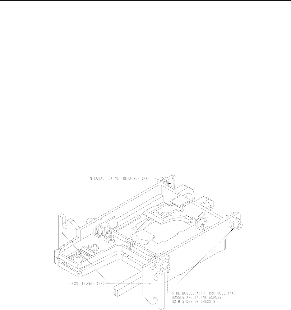
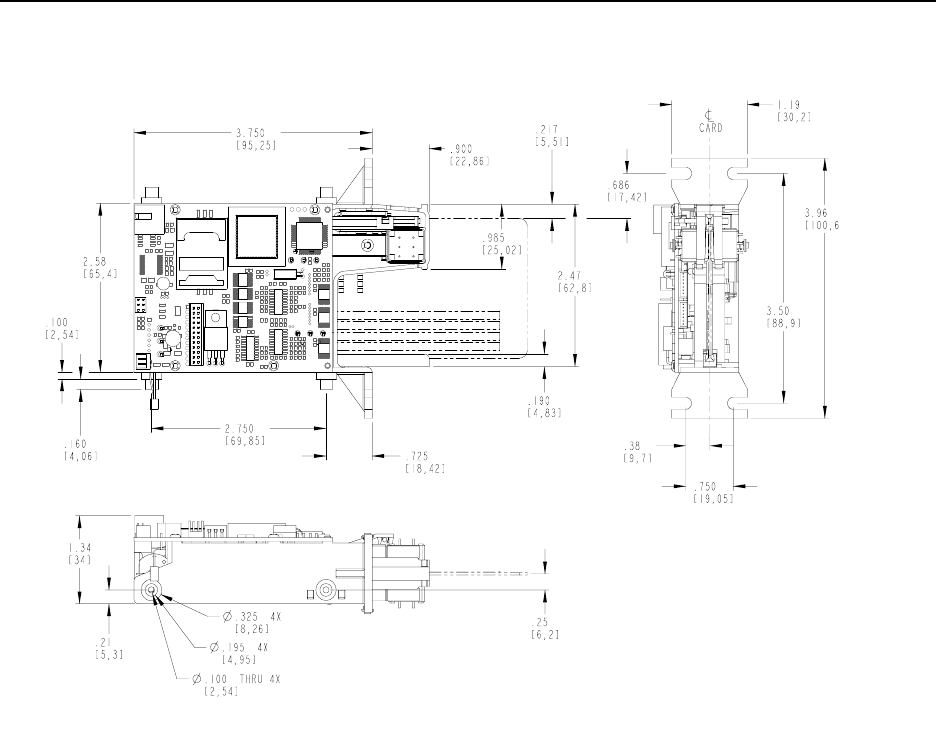
Chassis mounting features are shown in Figure 2-1. Mounting dimensions are shown in Figure 2-2.
Descriptions of the mounting options are as follows:
IntelliStripe 65, USB/RS-232 Insertion Reader
8
Front Flange
Two molded flanges toward the front of the chassis (Figure 2-1) connect the Reader by four
threaded studs, nuts, and washers. The International Bezel is used with the Front Flange.
Side Mounting Studs
There are four molded studs. Two are located on each side of the chassis. The North American
Bezel is used with side mounting studs. Optional threaded inserts can be inserted in both ends of
the studs and used with imperial screws, as indicated in Figure 2-1.
Side Mounting Holes
Four molded holes are available when studs are not provided. Holes are positioned in line with
the centerline of the stud with molded nut retaining features, as shown in Figure 2-1 and Figure
2-2.
Figure 2-1. Chassis Mounting Features
Section 2. Installation
9
0.100 = Dimensions in inches
[2,54 ] = Dimensions in millimeters
Figure 2-2. Dimensions For Mounting
IntelliStripe 65, USB/RS-232 Insertion Reader
10
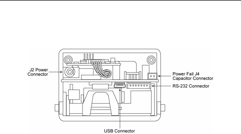
ELECTRICAL CONNECTIONS
Connectors
Figure 2-3 shows the positions of the rear connectors for power and communication.
Figure 2-3. Power and Communication Connections
Host Connector - RS-232
The RS-232 connector, J1, connects to the host’s power and RS-232 signals. Figure 2-3 shows
the location of the 7-pin RS-232 Connector. Table 2-1 lists the pin numbers of the connector. If
the RS-232 connection is used, the power can be supplied through the jack on the RS-232 cable
(see Figure 2-10) or via the J2 Power Connector.
Host Connector - USB
The USB connector, J11, connects to the host’s USB port. When using the USB connection,
power must be supplied via the J2 Power Connector on the back of the IntelliStripe 65. If the
USB connection is used, the power must be supplied to the J2 Power Connector.
Power-Fail Capacitor Connector
The Power-Fail Capacitor connector, J4, connects to an optional external capacitor that is used to
unlatch the card during a power failure. Pin 1 connects to the positive side of the capacitor and
pin 2 connects to the negative side (see Appendix A. Options, Power-Fail Latch Release
Option).
Section 2. Installation
11
Figure 2-4. Fully Equipped Contactless Reader with Antenna in Bezel
Contactless Installation
Some models of the IntelliStripe 65 include the ability to add a contactless smart card module.
The contactless module and its interface cable can be ordered separately from MagTek. Figure
2-5 shows how the cable and module are attached to the IntelliStripe 65 circuit board. Figure 2-6
shows the module fully installed.

IntelliStripe 65, USB/RS-232 Insertion Reader
12
Figure 2-5. Installing Contactless Module on Contactless Ready Model

Section 2. Installation
13
Figure 2-6. Contactless Module Installed
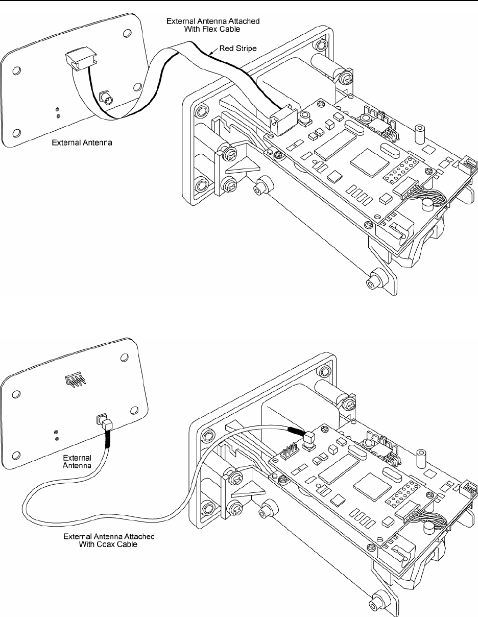
Antenna Installation
The antenna is a separate item that can be installed outside of the IntelliStripe 65. The antenna
module and the interface cable are supplied separately from the reader. Two types of cables are
offered:
• Flat Ribbon Cable – this cable is only 7.5” (19cm) but all 4 of the LEDs are supported
(see Figure 2-7)
• Coax Cable – this 12” (30cm) cable offers a slightly greater range of antenna placement
but it does not operate the LEDs on the antenna module (see Figure 2-8)
IntelliStripe 65, USB/RS-232 Insertion Reader
14
Figure 2-7. Using External Antenna with LEDs (Ribbon Cable)
Figure 2-8. Using External Antenna without LEDs (Coax Cable)
Section 2. Installation
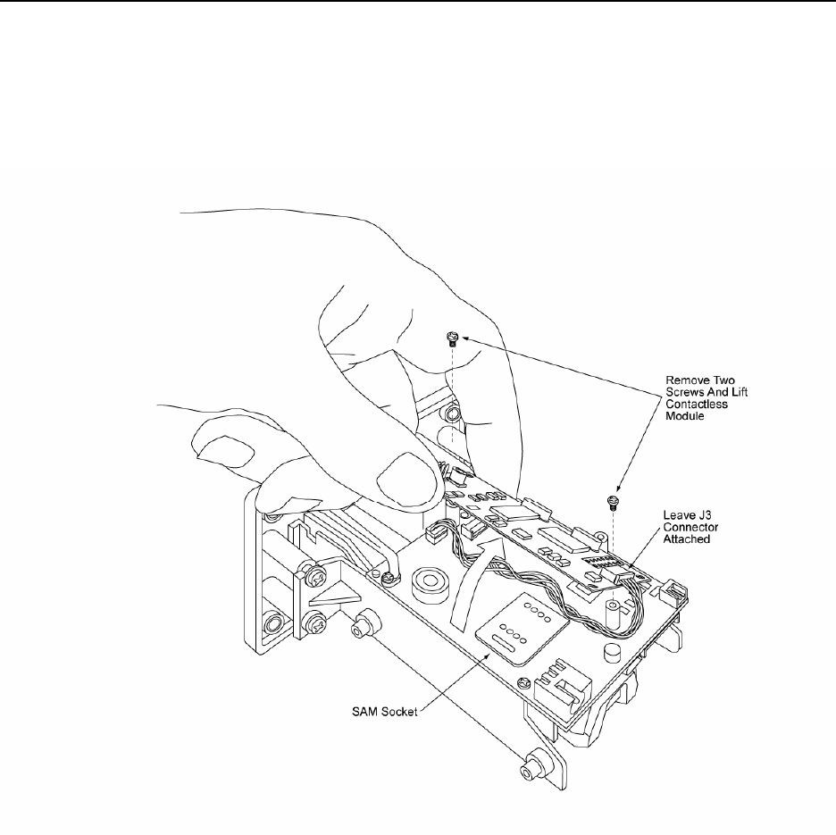
15
Accessing SAM Module
If the contactless module is installed, it must be removed temporarily in order to access the SAM
module. The two screws holding the contactless module onto the IntelliStripe 65 circuit board
will have to be removed in order to reach the SAM module which is located under the
contactless module (see Figure 2-9).
Figure 2-9. Removing Contactless Module to Access SAM Socket
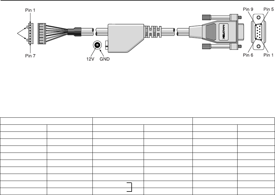
RS-232 Cable
Figure 2-10 shows the cable (P/N 16051408) that connects the IntelliStripe 65 (7-Pin Connector)
to the host (9-pin Connector). The length of the cable is 6’ (1.8m).
IntelliStripe 65, USB/RS-232 Insertion Reader
16
Locking
Tabs
Figure 2-10. RS-232 Cable
Table 2-1 lists the connector pin numbers and signal names.
Table 2-1. Pin List for RS-232 IntelliStripe 65 Cable
Molex 7 Pin (51065-0700) DE-9 Female 2.5mm Power Jack
Pin Number Signal Name Pin Number Signal Name
1 TXD 2 RXD
2 +12V CENTER PIN +12V
3 PWR GND SHELL GND
4 RXD 3 TXD
5 RTS 8 CTS
6 CTS 7 RTS
7 SIGNAL GND 5 GND
6 DSR
4 DTR
USB Cable
The USB cable is available in Pearl White (P/N 16051430) and MagTek Gray (P/N 16051433).
It connects the Host (USB-A plug) to the IntelliStripe 65 (USB mini-B plug). The overall length
of the cables is 6’ (1.8m).
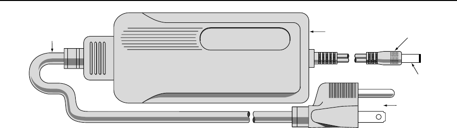
Power Supply
Figure 2-11 shows the Power Supply (P/N 64300080) 100-240V, regulated, 12VDC @ 1.5
Amps, 2.5 mm power jack. The AC power cord (P/N 71100001) is for use in North America.
Other users must supply their own cord (requires an IEC-320-C13 connector at the power
supply).
Section 2. Installation
17
3 Prong
Connector
12VDC Plug
GND
Auto Range
Power Supply
North American
100V–240V
Power Cord
Figure 2-11. Power Supply

IntelliStripe 65, USB/RS-232 Insertion Reader
18

IntelliStripe 65, USB/RS-232 Insertion Reader
20
POWER-FAIL LATCH RELEASE OPTION
The externally mounted power-fail capacitor is shown in Figure A-2.
Figure A-2. Latch Release Capacitor
The power fail unlatch option disengages the latch during a power failure event. This option is
triggered when the main input power to the reader fails. An external backup capacitor is
required for this option to function. This capacitor can be connected to the reader through a
header on the board.
In the case of power failure, the capacitor automatically opens the latch, which releases the card.
The users must determine the wire length required for their specific application. The power fail
capacitor range is 3300uF to 15000uF with a rated voltage greater than the applied reader input
voltage.

IntelliStripe 65, USB/RS-232 Insertion Reader
22
23
APPENDIX B. BEZEL CONFIGURATION AND MOUNTING
Three bezel configurations are described in this appendix: the International and the North
American Plastic Bezels and the International Metal Bezel. The International Bezels are slightly
larger than the North American Bezel and require a larger panel opening for installation. The
International Bezels are suited to applications requiring metric screws and the North American
Bezel to imperial screws. From the drawings in this section, the user may design a bezel for
different requirements.
INTERNATIONAL PLASTIC BEZEL MOUNTING
The International Plastic Bezel (P/N 21161202) is attached to the unit by four screws (Mounting
inserts M3.5 x 5 Minimum Deep). The four screws are inserted into the front flange slots to
retain the unit to the bezel. Figure B-1 shows the position and the dimensions of the flanges.
Figure B-2 shows the orientation and dimensions of the bezel and recommended dimensions for
the panel opening. Four screws that mount the Bezel to the panel are also M3.5. The length of
the screws depends on the panel thickness, washers, and spacers used in mounting the panel.
Figure B-1. Flanges for International Bezel Mounting
IntelliStripe 65, USB/RS-232 Insertion Reader
24
Mounting Inserts For Screws (4 pl)
#M3.5 x 5 Minimum Deep 26 Pin
Connector
26 Pin
Connector
Clearance
For M3,5
Screw (4pl)
Capacitor
Connector Head (In
2 Head Unit)
4.65"
118.11 mm
0.37"
9.40 mm
0.17"
4.32 mm
2.10"
53.54 mm
1.60"
40.64 mm
2.35"
59.69 mm
3.50"
88.90 mm
2.80"
71.12 mm
4.00"
101.60 mm
0.13"
3.30 mm
0.31"
7.87 mm
0.34"
8.64 mm
2.98"
75.69 mm
4.24"
107.70 mm
Motor
PCB Board
Figure B-2. International Plastic Bezel Mounting

Appendix B. Bezel Configuration and Mounting
25
INTERNATIONAL METAL BEZEL MOUNTING
The International Metal Bezel (P/N 21161204) is shown and described in Figure B-3. The Bezel
also requires the front flanges for attaching the Bezel to the unit (see Figure B-1). Four screws
are inserted into the front flange slots to retain the unit to the bezel. These screws are thread
cutting and may be either Phillips head or T10 Torx®.
Figure B-3 also shows the orientation and dimensions of the bezel and recommended dimensions
for the panel opening. Four screws that mount the Bezel to the panel are also M3.5. The length
of the screws depends on the panel thickness, washers, and spacers used in mounting the panel.
Compatibility
The Metal Bezel is not compatible with some units. The units compatible with the Metal Bezel
are 1) front mount and 2) front and side mount together (M1 and M3). The units not compatible
with the Metal Bezel are 1) side mount and 2) no mount (M2 and M4). Table B1 lists examples
of units compatible with the Metal Bezel. Table B2 lists examples of units not compatible with
the Metal Bezel.
Table B1. Examples of Configurations Compatible with the Metal Bezel
Part Number Model Mounting Description
21165044 IntelliStripe 65 M3 – Front and Side Mounted I65 with flanges and bosses
21165046 IntelliStripe 65 M3 – Front and Side Mounted I65 with flanges and bosses
21165048 IntelliStripe 65 M3 – Front and Side Mounted I65 with flanges and bosses
21165051 IntelliStripe 65 M3 – Front and Side Mounted I65 with flanges and bosses
21165052 IntelliStripe 65 M3 – Front and Side Mounted I65 with flanges and bosses
Table B2. Examples of Configurations Not Compatible with the Metal Bezel
Part Number Model Mounting Description
21165042 IntelliStripe 65 M2 – Side Mounted I65 with bosses only
21165043 IntelliStripe 65 M2 – Side Mounted I65 with bosses only
IntelliStripe 65, USB/RS-232 Insertion Reader
26
Mounting Inserts For Screws (4 pl)
#M3.5 x 5 Minimum Deep 26 Pin
Connector
26 Pin
Connector
Clearance
For #M3,5 x 5
Screw (4pl)
Capacitor
Connector Head (In
2 Head Unit)
4.58"
116.33 mm
0.575"
14.60 mm
0.250"
6.35 mm
1.77"
44.96 mm
1.188"
30.18 mm
2.42"
61.47 mm
3.50"
88.90 mm
2.85"
72.39 mm
4.00"
101.60 mm
0.325"
8.25 mm
0.291"
7.39 mm
0.25"
6.35 mm
2.60"
66.04 mm
3.94"
100.08 mm
Motor
PCB Board
Figure B-3. International Metal Bezel Mounting

Appendix B. Bezel Configuration and Mounting
27
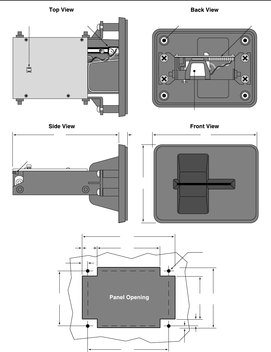
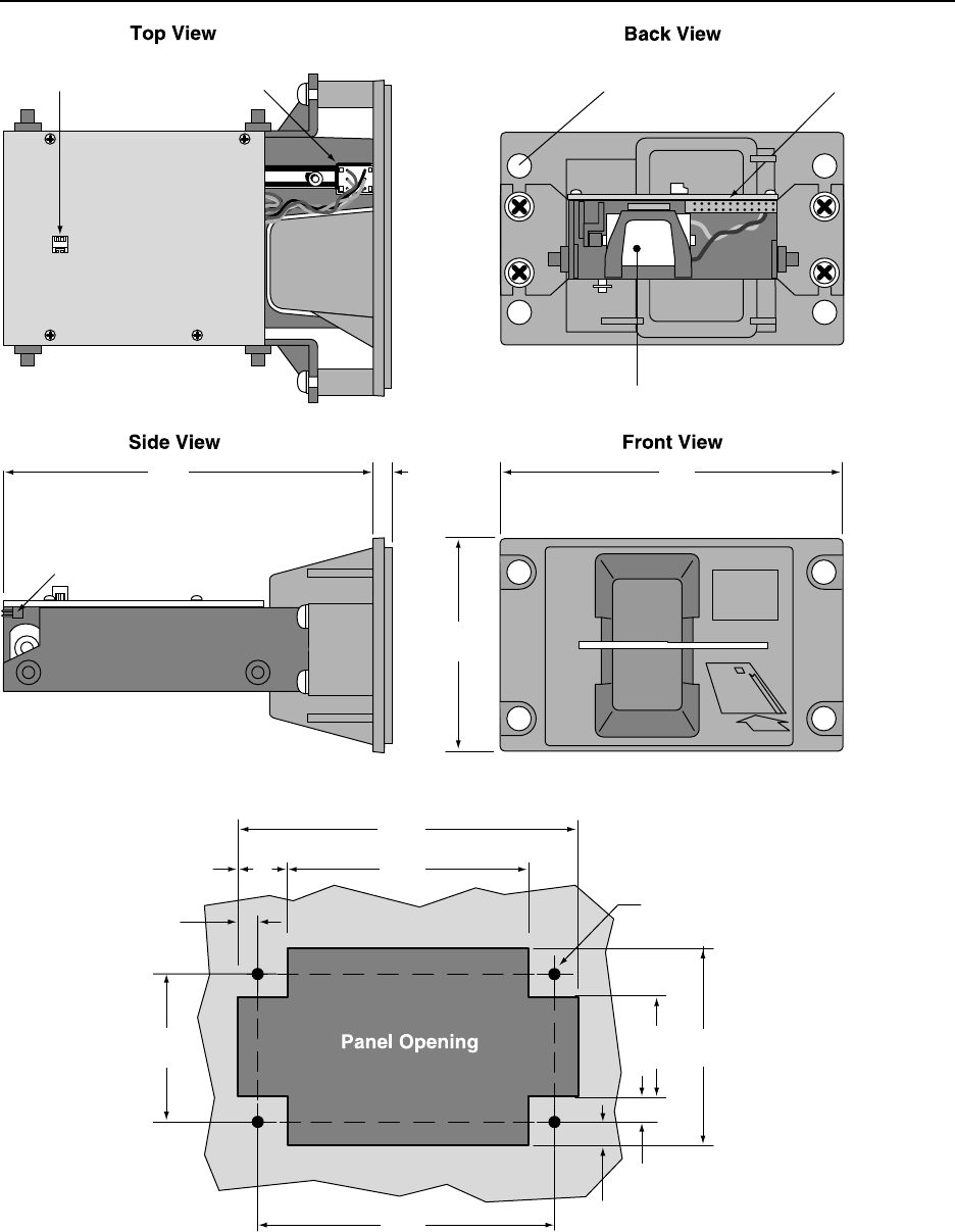
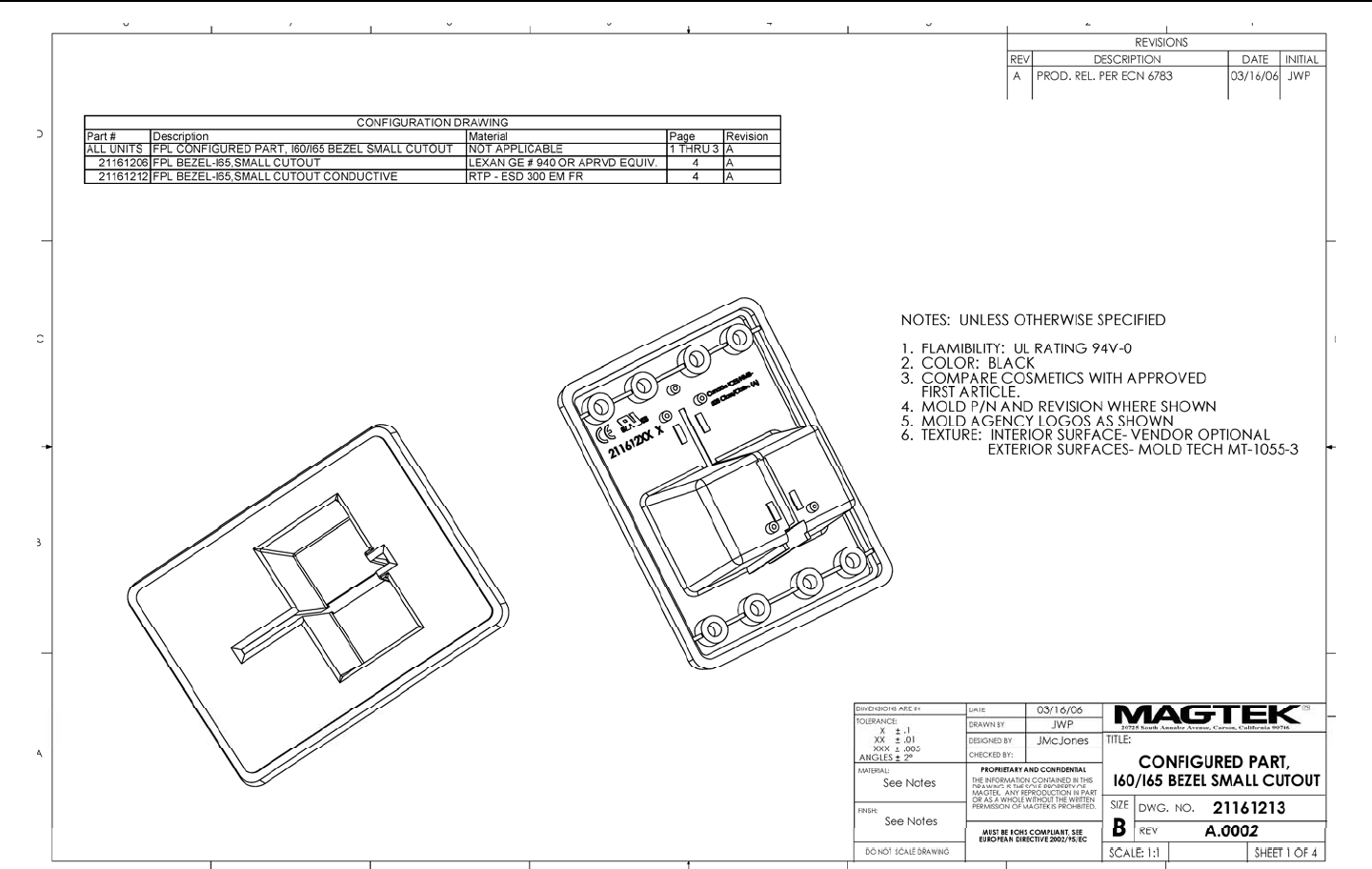
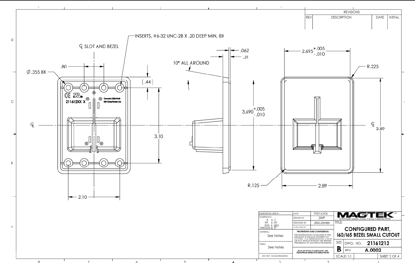
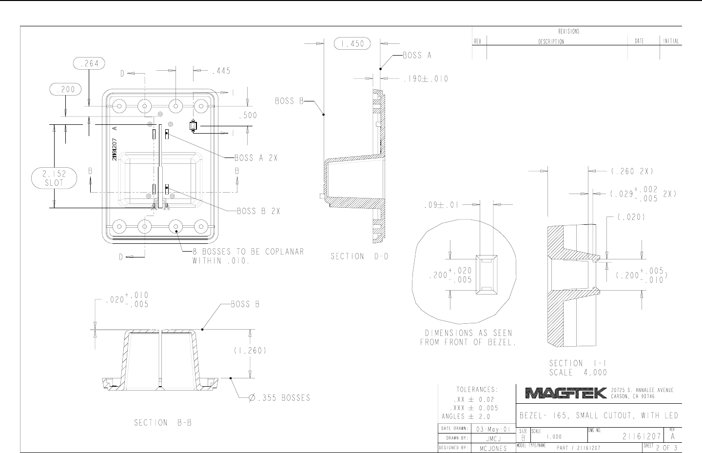
NORTH AMERICAN PLASTIC BEZEL MOUNTING
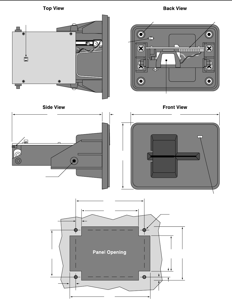
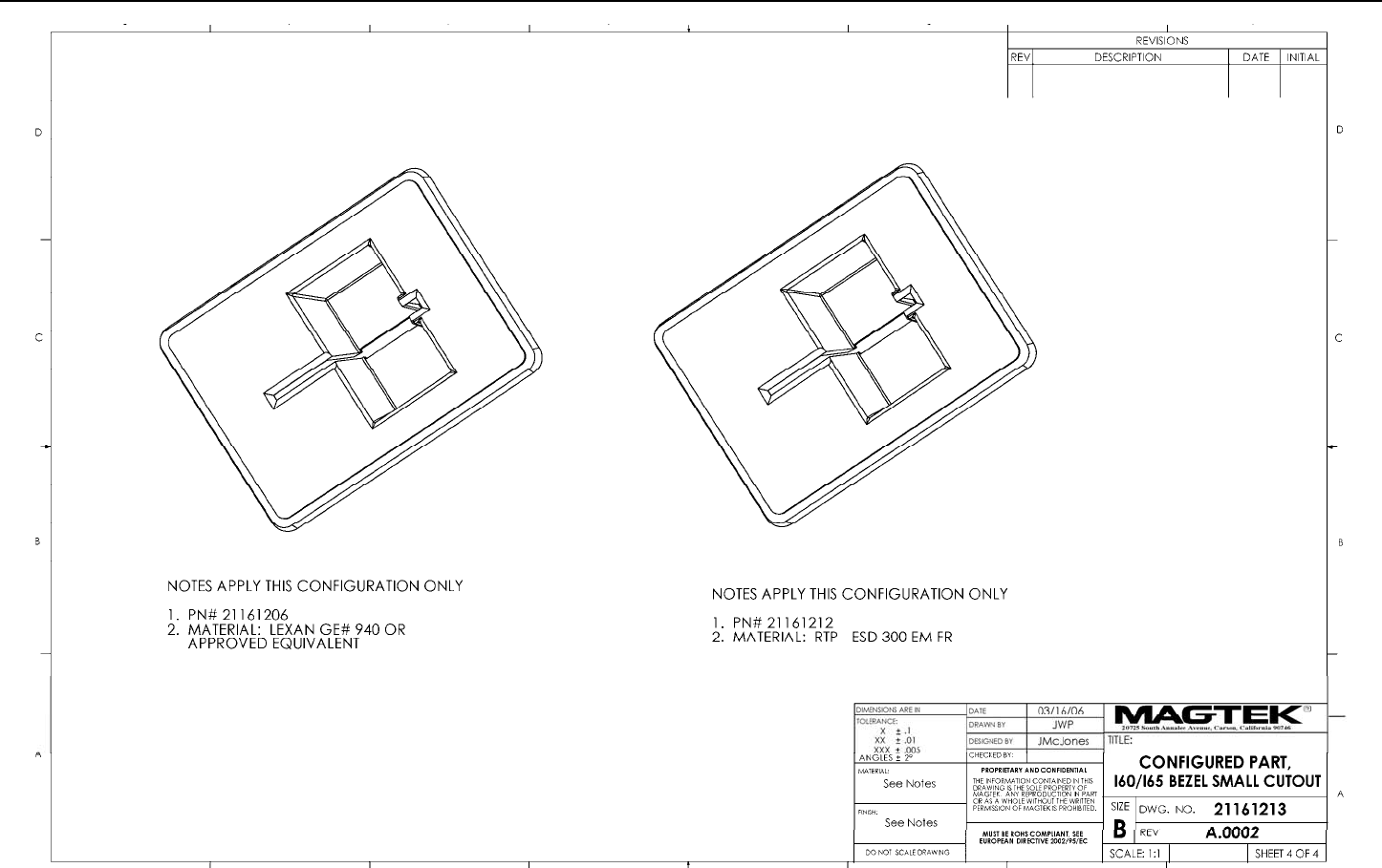
The North American Plastic Bezel (P/N 21161206) is shown and described on Figures B-4, B-5,
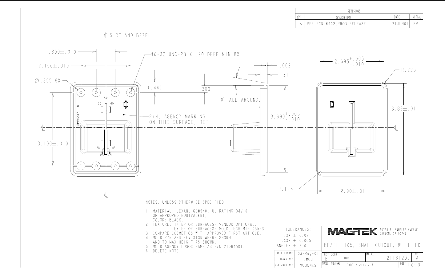
B-6 and B7. The Bezel with the optional cutout for the LED (P/N 21161207) is shown and
described on Figures B-4, B-9, and B-10. The North American Bezel is smaller than the
International Bezels and requires a smaller panel opening for installation. The North American
Bezel is suited to applications requiring imperial screws. From the drawings in this section, the
user may design a bezel for different requirements.
Figure B-3 shows the orientation and dimensions of the bezel and recommended dimensions for
the panel opening. Four screws that mount the Bezel to the panel are size 6-32. The length of
the screws depends on the panel thickness, washers, and spacers used in mounting the panel.
Figures B-4 and B-5 show the dimensions of the bezel in case a different bezel is required.
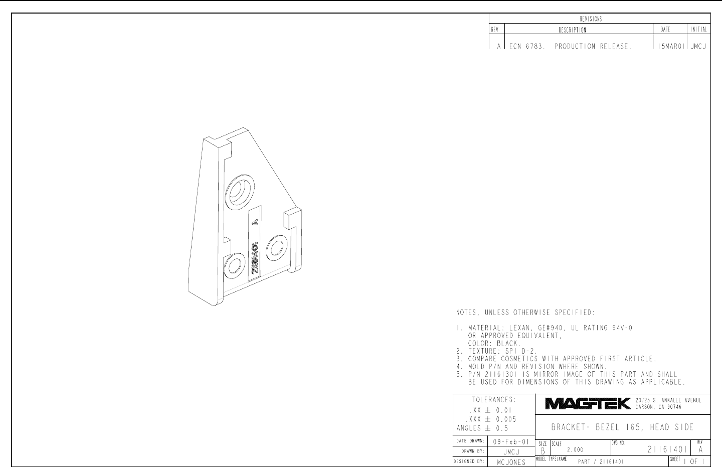
Figures B-6 and B-7 show the brackets that are mounted on the side of the unit.
IntelliStripe 65, USB/RS-232 Insertion Reader
28
4-40 X 3/8 Screw,
Pan hd, phillips (2pl)
Mounting Inserts For Screws (8 pl)
#6-32 X .20 Minimum Deep
Optional
LED
Cutout
26 Pin
Connector
Optional
LED
Cutout
26 Pin
Connector
Clearance
For 6-32
Screw (4pl)
Capacitor
Connector
Motor
PCB Board
4.65"
118.11 mm
0.275"
6.98 mm
0.25"
6.35 mm
2.10"
53.54 mm
1.60"
40.64 mm
2.35"
59.69 mm
3.65"
92.71 mm
2.60"
66.04 mm
3.10"
78.74 mm
0.125"
3.18 mm
0.25"
6.35 mm
0.31"
7.87 mm
2.97"
75.44 mm
3.96"
100.58 mm
Figure B-4. North American Plastic Bezel Mounting
Appendix B. Bezel Configuration and Mounting
29
Figure B-5. Small Cutout Bezel (1)
IntelliStripe 65, USB/RS-232 Insertion Reader
30
Figure B-6. Small Cutout Bezel (2)

Appendix B. Bezel Configuration and Mounting
31
Figure B-7. Small Cutout Bezel (3)
IntelliStripe 65, USB/RS-232 Insertion Reader
32
Figure B-8. Small Cutout Bezel (4)
Appendix B. Bezel Configuration and Mounting
33
Figure B-9. Head-Side Bezel Bracket
IntelliStripe 65, USB/RS-232 Insertion Reader
34
Figure B-10. North American Plastic Bezel with LED Cutout (1)
Appendix B. Bezel Configuration and Mounting
35
Figure B-11. North American Plastic Bezel with LED Cutout (2)

IntelliStripe 65, USB/RS-232 Insertion Reader
36
Figure B-12. North American Plastic Bezel with LED Cutout (3)