Magtek orporated 30056017 DynaPro User Manual v3 99875586 1 01
Magtek Incorporated DynaPro Users Manual v3 99875586 1 01
Users Manual

DYNAPRO
INSTALLATION AND OPERATION MANUAL
PART NUMBER: 99875586 REV 1
AUGUST 2013
REGISTERED TO ISO 9001:2008
1710 Apollo Court
Seal Beach, CA 90740
Phone: (562) 546-6400
FAX: (562) 546-6301
Technical Support: (651) 415-6800
www.magtek.com
ii

iii
Copyright© 2007 - 2012
MagTek®, Inc.
Printed in the United States of America
Information in this document is subject to change without notice. No part of this document may
be reproduced or transmitted in any form or by any means, electronic or mechanical, for any
purpose, without the express written permission of MagTek, Inc.
MagTek is a registered trademark of MagTek, Inc.
MagneSafe™ is a trademark of MagTek, Inc.
IPAD® is a trademark of MagTek, Inc.
MagnePrint® is a trademark of MagTek, Inc.
REVISIONS
Rev
Number Date Notes
1.01 August 15, 2012 Initial Release
2.01 July 18, 2013
iv
LIMITED WARRANTY
MagTek warrants that the products sold pursuant to this Agreement will perform in accordance with MagTek’s
published specifications. This warranty shall be provided only for a period of one year from the date of the
shipment of the product from MagTek (the “Warranty Period”). This warranty shall apply only to the “Buyer”
(the original purchaser, unless that entity resells the product as authorized by MagTek, in which event this
warranty shall apply only to the first repurchaser).
During the Warranty Period, should this product fail to conform to MagTek’s specifications, MagTek will, at its
option, repair or replace this product at no additional charge except as set forth below. Repair parts and
replacement products will be furnished on an exchange basis and will be either reconditioned or new. All replaced
parts and products become the property of MagTek. This limited warranty does not include service to repair
damage to the product resulting from accident, disaster, unreasonable use, misuse, abuse, negligence, or
modification of the product not authorized by MagTek. MagTek reserves the right to examine the alleged
defective goods to determine whether the warranty is applicable.
Without limiting the generality of the foregoing, MagTek specifically disclaims any liability or warranty for
goods resold in other than MagTek’s original packages, and for goods modified, altered, or treated without
authorization by MagTek.
Service may be obtained by delivering the product during the warranty period to MagTek (1710 Apollo Court,
Seal Beach, CA 90740). If this product is delivered by mail or by an equivalent shipping carrier, the customer
agrees to insure the product or assume the risk of loss or damage in transit, to prepay shipping charges to the
warranty service location, and to use the original shipping container or equivalent. MagTek will return the
product, prepaid, via a three (3) day shipping service. A Return Material Authorization (“RMA”) number must
accompany all returns. Buyers may obtain an RMA number by contacting Technical Support at (888) 624-8350.
EACH BUYER UNDERSTANDS THAT THIS MAGTEK PRODUCT IS
OFFERED AS IS. MAGTEK MAKES NO OTHER WARRANTY, EXPRESS OR
IMPLIED, AND MAGTEK DISCLAIMS ANY WARRANTY OF ANY OTHER
KIND, INCLUDING ANY WARRANTY OF MERCHANTABILITY OR FITNESS
FOR A PARTICULAR PURPOSE.
IF THIS PRODUCT DOES NOT CONFORM TO MAGTEK’S SPECIFICATIONS, THE SOLE REMEDY
SHALL BE REPAIR OR REPLACEMENT AS PROVIDED ABOVE. MAGTEK’S LIABILITY, IF ANY,
SHALL IN NO EVENT EXCEED THE TOTAL AMOUNT PAID TO MAGTEK UNDER THIS
AGREEMENT. IN NO EVENT WILL MAGTEK BE LIABLE TO THE BUYER FOR ANY DAMAGES,
INCLUDING ANY LOST PROFITS, LOST SAVINGS, OR OTHER INCIDENTAL OR CONSEQUENTIAL
DAMAGES ARISING OUT OF THE USE OF, OR INABILITY TO USE, SUCH PRODUCT, EVEN IF
MAGTEK HAS BEEN ADVISED OF THE POSSIBILITY OF SUCH DAMAGES, OR FOR ANY CLAIM BY
ANY OTHER PARTY.
LIMITATION ON LIABILITY
EXCEPT AS PROVIDED IN THE SECTIONS RELATING TO MAGTEK’S LIMITED WARRANTY,
MAGTEK’S LIABILITY UNDER THIS AGREEMENT IS LIMITED TO THE CONTRACT PRICE OF THIS
PRODUCT.
MAGTEK MAKES NO OTHER WARRANTIES WITH RESPECT TO THE PRODUCT, EXPRESSED OR
IMPLIED, EXCEPT AS MAY BE STATED IN THIS AGREEMENT, AND MAGTEK DISCLAIMS ANY
IMPLIED WARRANTY, INCLUDING WITHOUT LIMITATION ANY IMPLIED WARRANTY OF
MERCHANTABILITY OR FITNESS FOR A PARTICULAR PURPOSE.
MAGTEK SHALL NOT BE LIABLE FOR CONTINGENT, INCIDENTAL, OR CONSEQUENTIAL
DAMAGES TO PERSONS OR PROPERTY. MAGTEK FURTHER LIMITS ITS LIABILITY OF ANY KIND
WITH RESPECT TO THE PRODUCT, INCLUDING ANY NEGLIGENCE ON ITS PART, TO THE
CONTRACT PRICE FOR THE GOODS.
MAGTEK’S SOLE LIABILITY AND BUYER’S EXCLUSIVE REMEDIES ARE STATED IN THIS SECTION
AND IN THE SECTION RELATING TO MAGTEK’S LIMITED WARRANTY.

v
FCC WARNING STATEMENT
This equipment has been tested and found to comply with the limits for a Class B digital device,
pursuant to part 15 of the FCC Rules. These limits are designed to provide reasonable protection against
harmful interference in a residential installation. This equipment generates, uses and can radiate radio
frequency energy and, if not installed and used in accordance with the instructions, may cause harmful
interference to radio communications. However, there is no guarantee that interference will not occur in
a particular installation. If this equipment does cause harmful interference to radio or television
reception, which can be determined by turning the equipment off and on, the user is encouraged to try to
correct the interference by one or more of the following measures:
—Reorient or relocate the receiving antenna.
—Increase the separation between the equipment and receiver.
—Connect the equipment into an outlet on a circuit different from that to which the receiver is
connected.
—Consult the dealer or an experienced radio/TV technician for help.
FCC COMPLIANCE STATEMENT
This device complies with Part 15 of the FCC Rules. Operation of this device is subject to the following
two conditions: (1) this device may not cause harmful interference, and (2) this device must accept any
interference received, including interference that may cause undesired operation.
CUR/UR
This product is recognized per Underwriter Laboratories and Canadian Underwriter Laboratories 1950.
RoHS STATEMENT
When ordered as RoHS compliant, this product meets the Electrical and Electronic Equipment (EEE) Reduction
of Hazardous Substances (RoHS) European Directive 2011/65/EC. The marking is clearly recognizable, either
as written words like “Pb-free”, “lead-free”, or as another clear symbol ( ).
vii
Table of Contents
SECTION 1: INTRODUCTION AND SPECIFICATIONS ............................................................................. 1
Product Description .................................................................................................................................. 1
Design Objectives ..................................................................................................................................... 1
Securing Personal Cardholder Data ..................................................................................................... 1
Protection for all Points within the Payment Infrastructure .................................................................. 1
Security and Ease of Integration by Design ......................................................................................... 1
Greater Flexibility Reduces Total Cost of Ownership .......................................................................... 1
Design Features ....................................................................................................................................... 2
Major Components ................................................................................................................................... 3
Specifications ............................................................................................................................................ 5
Pinout on RJ-12 (or RJ-25) 6-pin Connector ............................................................................................ 6
SECTION 2: SYSTEM REQUIREMENTS & DEVICE FEATURES ............................................................. 7
System Requirements .............................................................................................................................. 7
Device Features ........................................................................................................................................ 7
Physical and Electronic Security .......................................................................................................... 7
Sleep Mode .......................................................................................................................................... 7
Liquid Crystal Display ........................................................................................................................... 7
Function Buttons (Soft Keys) ................................................................................................................ 7
10-Digit Numeric Pad ........................................................................................................................... 7
Magnetic Card Reading ........................................................................................................................ 7
ICC Card Reading ................................................................................................................................ 8
SECTION 3: INSTALLATION....................................................................................................................... 9
Hardware Installation ................................................................................................................................ 9
Privacy Shield Installation ....................................................................................................................... 11
Privacy Shield Removal .......................................................................................................................... 11
Mounting Dimensions ............................................................................................................................. 12
SECTION 4: OPERATION .......................................................................................................................... 13
Overview ................................................................................................................................................. 13
Card Reading .......................................................................................................................................... 14
Manual Card Entry .................................................................................................................................. 15
Selecting the Card Type ......................................................................................................................... 15
PIN Entry ................................................................................................................................................. 16
Amount Verify ......................................................................................................................................... 16
Signature Capture ................................................................................................................................... 17
Status Codes .......................................................................................................................................... 17
SECTION 5: MAINTENANCE .................................................................................................................... 18
Cleaning .................................................................................................................................................. 18
Adjusting the LCD ................................................................................................................................... 18
viii
FIGURES
Figure 1-1. DYNAPRO with Optional Privacy Shield ............................................................................... 2
Figure 1-2. Major Components (front) ..................................................................................................... 3
Figure 1-3. Major Components (back) ..................................................................................................... 4
Figure 1-4. RJ12 (or RJ25) 6-Pin Connector ........................................................................................... 6
Figure 3-1. USB Interface ........................................................................................................................ 9
Figure 3-2. Installing the Privacy Shield ................................................................................................ 11
Figure 3-3. Removing the Privacy Shield ................................................ Error! Bookmark not defined.
Figure 3-4. Mounting Dimensions and Cable Access Hole ................................................................... 12
Figure 4-1. Example of Welcome Screen (Ready for a New Transaction) ........................................... 13
Figure 4-2. Example of Swipe Card Screen .......................................................................................... 14
Figure 4-3. Swiping a Card Through the DYNAPRO............................................................................. 14
Figure 4-4. Example of User Screen to Manually Enter Card Data ....................................................... 15
Figure 4-5. Example of User Screen to Select Card Type .................................................................... 15
Figure 4-6. Example of User Screen to Enter PIN ................................................................................. 16
Figure 4-7. Example of User Screen to Verify Amount ......................................................................... 16
Figure 4-8. Example of User Screen to Enter Signature ....................................................................... 17
Figure 5-2. Adjusting the DYNAPRO’s LCD .......................................................................................... 18
1
SECTION 1: INTRODUCTION AND SPECIFICATIONS
PRODUCT DESCRIPTION
The DYNAPRO is a secure PIN entry device combined with MagTek’s 3-Track MagneSafe™
secure card reader. The DYNAPRO provides the most comprehensive end-to-end security
solution to prevent personal cardholder data breaches while bringing convenience and speed to
Retail and Financial transactions.
DESIGN OBJECTIVES
Securing Personal Cardholder Data
The DYNAPRO immediately encrypts data at the point of swipe to safeguard personal
information encoded on the magnetic stripe. The encryption takes place within an encapsulated
magnetic read head as the card is swiped, eliminating the chance of intercepting clear text data.
The DYNAPRO’s data encryption scheme uses the industry standard TDEA (3DES) algorithm,
which offers merchants, processors, issuers and acquirers the flexibility to manage decryption
services themselves or to outsource, thereby avoiding the risk imposed by unproven, proprietary
encryption algorithms.
Protection for all Points within the Payment Infrastructure
In addition to meeting the requirements established by PCI PTS v3.x, which incorporates SRED
features, the DYNAPRO has MagnePrint®, a proven embedded security feature that
authenticates the debit, credit, or gift card and its encoded track data, rendering counterfeit or
cloned cards useless. So even if cardholder data is acquired for the purpose of manufacturing
counterfeit cards, such cards can be detected, the transaction can be declined, and the criminal
can be prosecuted. The MagnePrint feature provides a valuable defense to protect the merchant,
the acquirer, the processor, the card issuer, and ultimately the consumer.
Security and Ease of Integration by Design
In addition to securing clear text card data, the DYNAPRO uses a 32-bit secure processor which
incorporates flexible data formatting and masking capabilities for compatibility with existing
software and payment applications, eliminating the need for recertification.
The DYNAPRO supports Device Authentication so the retailer, processor, and acquirer have the
confidence of knowing that a rogue reader was not substituted and provides transparency to the
processor, acquirer, or ISO if the device is changed. Furthermore, it supports Mutual
Authentication through a secure challenge/response sequence, which eliminates both the
potential of being redirected to an illegitimate site and the ability to substitute a compromised
PINpad terminal.
Greater Flexibility Reduces Total Cost of Ownership
The DYNAPRO supports secure remote key injection, eliminating the need to return the unit in
the event a new key is required.
DYNAPRO Installation and Operation Manual
2
DESIGN FEATURES
PCI PTS v3.x Certified
TDEA (3DES) Encryption
DUKPT Key Management
Remote Key Injection
Card and Data Authentication
Device Authentication
Mutual Authentication
Flexible Data Formats
Flexible Data Masking
Real-time electronic signature capture (in some models)
USB HID Device or Ethernet Device
Optional Privacy Shield
Backlit color LCD graphics
ICC Card Reading
Contactless Card Reading
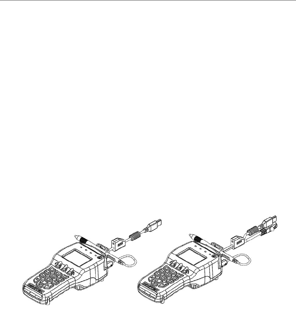
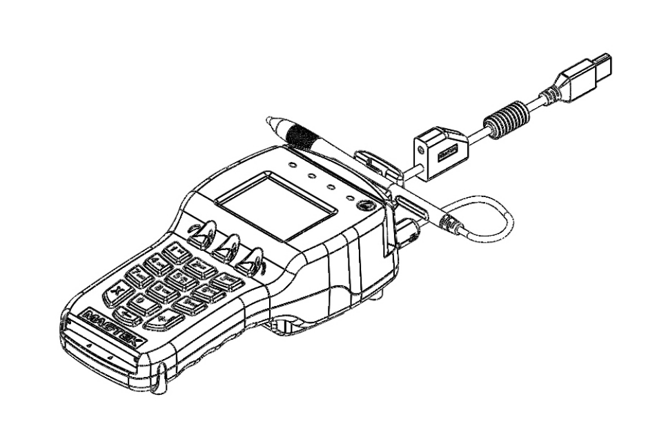
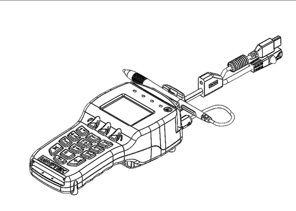
Figure 1-1. DYNAPRO USB and ETHERNET
Introduction and Specifications
3
MAJOR COMPONENTS
The major components of the DYNAPRO are shown in Figures 1-2, 1-3 and 1-4.
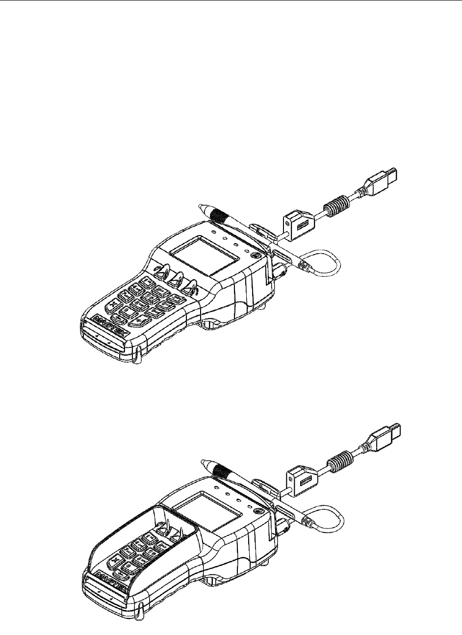
Note: The ferite bead must remain attached to the stylus cable at all times, do not remove.
Changes or modifications not expressly approved by Magtek could void the user's
authority to operate the equipment.
Figure 1-2. Major Components (front)
Figure 1-3. With Privacy Shield
DYNAPRO Installation and Operation Manual
4
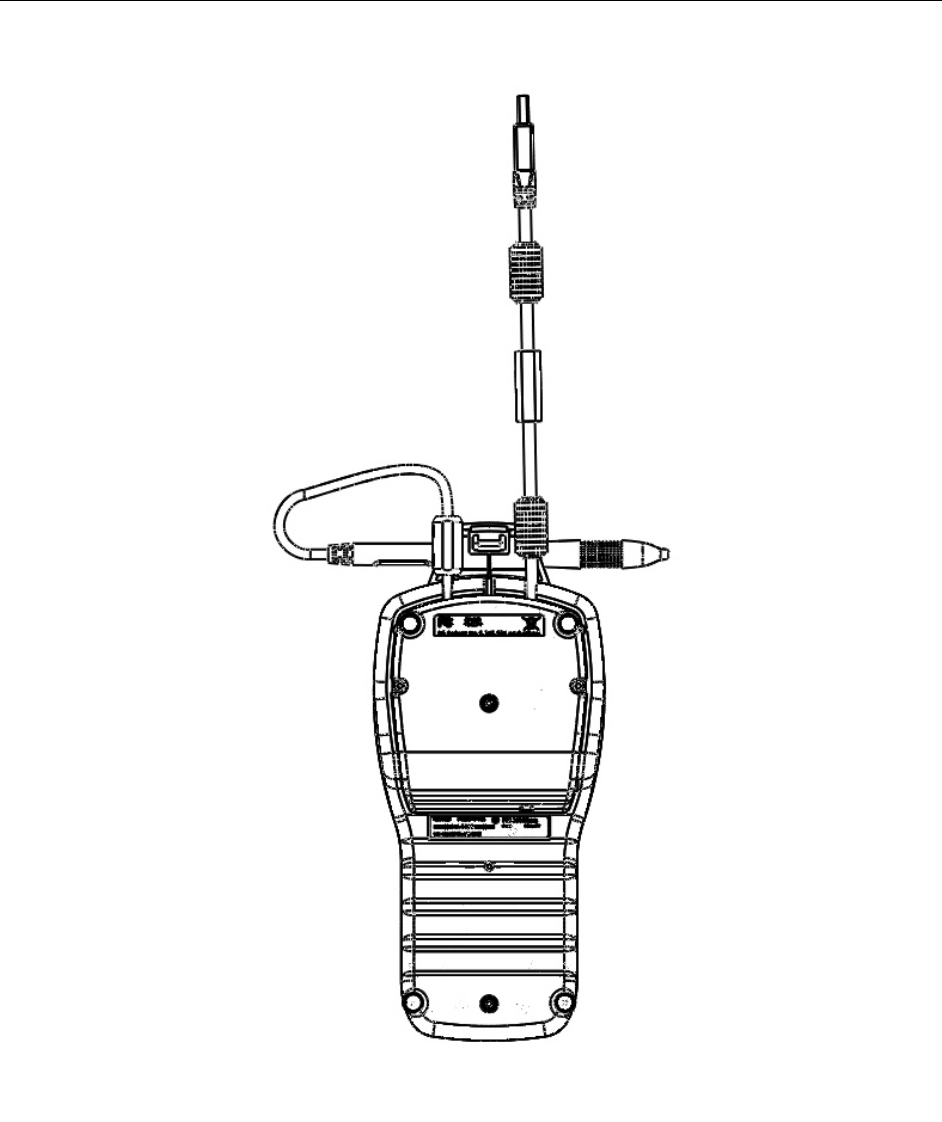
Figure 1-4. Major Components (back)

Introduction and Specifications
5
SPECIFICATIONS
Electrical
Power Input: USB Bus Powered
Voltage: 5VDC
Current: 250mA (900mA with contactless)
Interfaces: USB 2.0 (USB 1.1 compatible)
Display Type: Backlit, color liquid crystal display (LCD)
Display Resolution: 240 x 320 dpi
Flash Memory: 256 MBit
Internal SDRAM memory: 64 MBit
Battery type: Lithium
Mechanical
Dimensions (L x W x H): 8.8in x 3.9in x 2.4in (223.5mm x 99.1mm x 61.0mm)
Weight: 1 lb
Keypad: 16-key, includes 3 soft function keys associated with LCD
Cable Length (standard): 6.75 ft (2 m)
Card Reader: 3 track encrypting IntelliHead reader with MagnePrint
Connector Type: RJ25 modular jack
Environmental
Temperature:
Operating: 32 °F to 113 °F (0 °C to 45 °C)
Storage: 14 °F to 140 °F (-10 °C to 60 °C)
Relative Humidity:
Operating: 10% to 90% non-condensing at 23 °C
Storage: Up to 90% non-condensing
Reliability
Expected Life (unit): 1,000,000 card swipes (equivalent to 5 years of operation)
Battery Life: 5 years shelf life
DYNAPRO Installation and Operation Manual
6
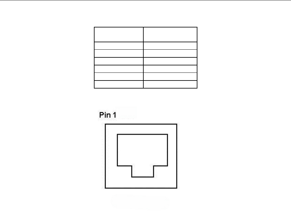
PINOUT ON RJ-25 6-PIN CONNECTOR
RJ25
Connector Signal
1 VBUS
2 USB_DM
3 USB_DP
4 GND
5 NC
6 CGND
Figure 1-5. RJ25 6-Pin Connector
7
SECTION 2: SYSTEM REQUIREMENTS & DEVICE
FEATURES
SYSTEM REQUIREMENTS
Windows XP or later (32-bit or 64-bit)
Microsoft .NET Framework version 2.0 (Not required but suggested)
USB port
Upon installation, Windows will automatically recognize and install the USB drivers for this
device.
DEVICE FEATURES
Physical and Electronic Security
The DYNAPRO enclosure and its associated electronics have been designed to form a Tamper
Resistant Security Module (TRSM). The covers are securely attached and incorporate sensing
circuits to detect if any attempt is made to open the unit. Internal spaces within the DYNAPRO
have been minimized to reduce the possibility of unauthorized modifications.
In addition, any attempt to penetrate or modify the DYNAPRO electronically will cause the unit
to permanently erase its stored encryption keys, after which the DYNAPRO will cease to
function.
Sleep Mode
When the Windows operating system shuts down or is suspended the DYNAPRO will enter into
a sleep mode.
Liquid Crystal Display
The Liquid Crystal Display (LCD) is a color graphics display capable of showing static or
animated messages.
Function Buttons (Soft Keys)
The three function buttons or soft keys are located below the LCD screen. These buttons are
programmable for use with display-based prompts.
10-Digit Numeric Pad
During normal operation the numeric keypad is used for PIN entries. An audio tone will provide
feedback when entering the PIN digits. There are three additional keys that may be used during
a transaction: an ENTER button (green), a CLEAR button (yellow), and a CANCEL button
(red).
Magnetic Card Reading
The DYNAPRO contains a MagneSafe card reader that encrypts card data at the point of swipe
to protect the cardholder’s personal information. The reader incorporates MagTek’s 3-track
encrypting IntelliHead, a magnetic read head which has encapsulated and securely potted

DYNAPRO Installation and Operation Manual
8
electronics that reads, decodes, and encrypts card data within the head. This technology secures
the magnetic stripe data at the earliest point in the transaction chain—the initial swipe.
In addition, as a card is swiped through the reader, through the use of MagnePrint technology the
card can be authenticated immediately, either by Magensa.net or by another system, to determine
whether the card is counterfeit or has been altered.
The card reader is capable of reading any ISO or AAMVA encoded magnetic stripe data.
ICC Card Reading
The DYNAPRO includes a smart card (ICC) reader. The card is inserted from the front of the
unit under the keypad.
Contactless Card Reading
The DYNAPRO includes an optional contactless card reader. The card is waved above the LCD.
9
SECTION 3: INSTALLATION
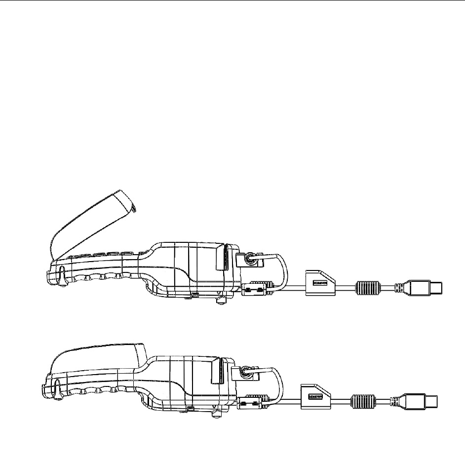
USB INSTALLATION
To connect the DYNAPRO to a computer, connect its USB cable to the USB port on the
computer as shown in Figure 3-1. Note: the standard USB cable P/N 30019317 is six feet long.
Warning
Connecting or disconnecting the USB cable from the back side of the DYNAPRO
when the computer is ON may clear the encryption keys.
Figure 3-1. USB Interface
ETHERNET INSTALLATION
DYNAPRO Installation and Operation Manual
10
Figure 3-2. Ethernet Interface
Installation
11
PRIVACY SHIELD INSTALLATION
To install the Privacy Shield, follow the steps below.
Place the clips of the open end of the Privacy Shield into the openings located just above the
contact card slot as shown in Figure 3-2.
Privot the shield down, locking the three clips into the holes located just above the function
buttons.
Figure 3-3. Installing the Privacy Shield
PRIVACY SHIELD REMOVAL
To remove the Privacy Shield, follow the steps below.
Grasp the Privacy Shield and slowly lift the edge closest to the LCD, pivoting the shield up to a
45 degree angle and remove the shield.
DYNAPRO Installation and Operation Manual
12
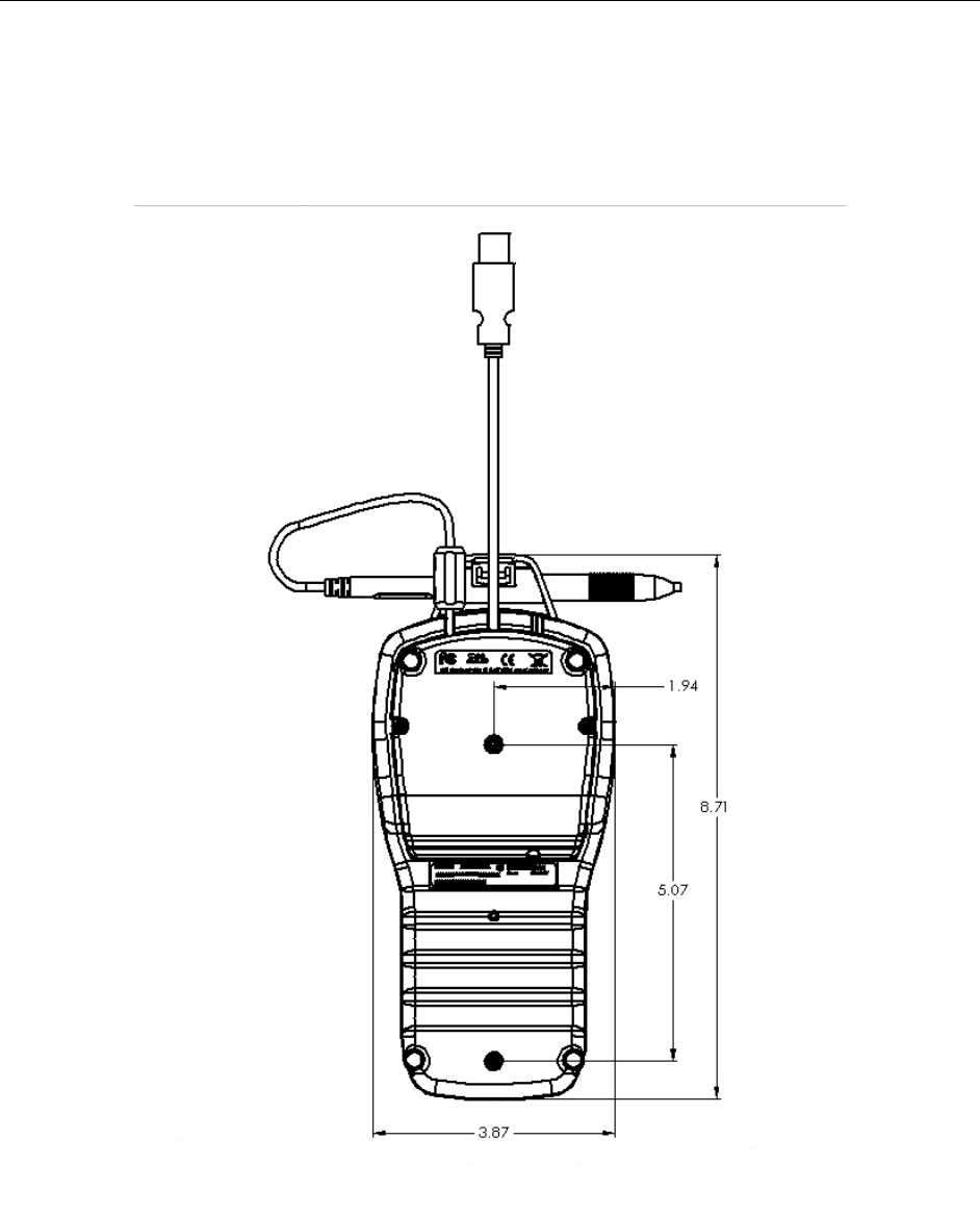
MOUNTING DIMENSIONS
The overall dimensions of the unit and the mounting hole locations are shown in Figure 3-4.
This drawing is not to scale and dimensions are given in inches. In addition, mounting the
DYNAPRO to a surface will require size # 4-40 screws.
Notes: All dimensions are XX= +/- 0.02 in inches.
Figure 3-4. Mounting Dimensions and Cable Access Hole

13
SECTION 4: OPERATION
OVERVIEW
During normal operation, the operator will select the type of transaction from the PC application
controlling the DYNAPRO and the cardholder will enter data on the DYNAPRO’s keypad in
response to prompts on its LCD. Transactions may include new accounts, teller window
applications, checking, savings, mortgages, retail transactions, or any other option where there is
interaction between the cardholder and the operator.
Note
Messages shown on the DYNAPRO are customized by the application
programmer; therefore, the sequence of prompts on the LCD and their contents
will vary depending on the requirements of the institution and may not correspond
to the example messages contained herein. Refer to appropriate personnel if
there are any questions about the prompts or any part of the operation.
The DYNAPRO will display “Welcome” on its LCD (see figure 4-1 for an example) to indicate
that it is ready to enter a new transaction.
Figure 4-1. Example of Welcome Screen (Ready for a New Transaction)
Typically, the cardholder is prompted to swipe his or her card through the DYNAPRO’s MSR to
initiate a transaction. If the card swipe failed to read the card data, the application may request
the user to reswipe the card or may ask the user to enter the card data manually. The application
may also need to prompt the user to identify the card type (e.g. Debit or Credit). If a PIN is
required (e.g. for a Banking or Debit card transaction), the application will prompt the cardholder
to enter his or her PIN. If your DYNAPRO has signature capture capability, the application will
prompt the user to enter his or her signature on the touch screen. For a more detailed discussion,
see the sections below on Card Reading, Manual Card Entry, PIN Entry, and Signature Capture.
DYNAPRO Installation and Operation Manual
14
CARD READING
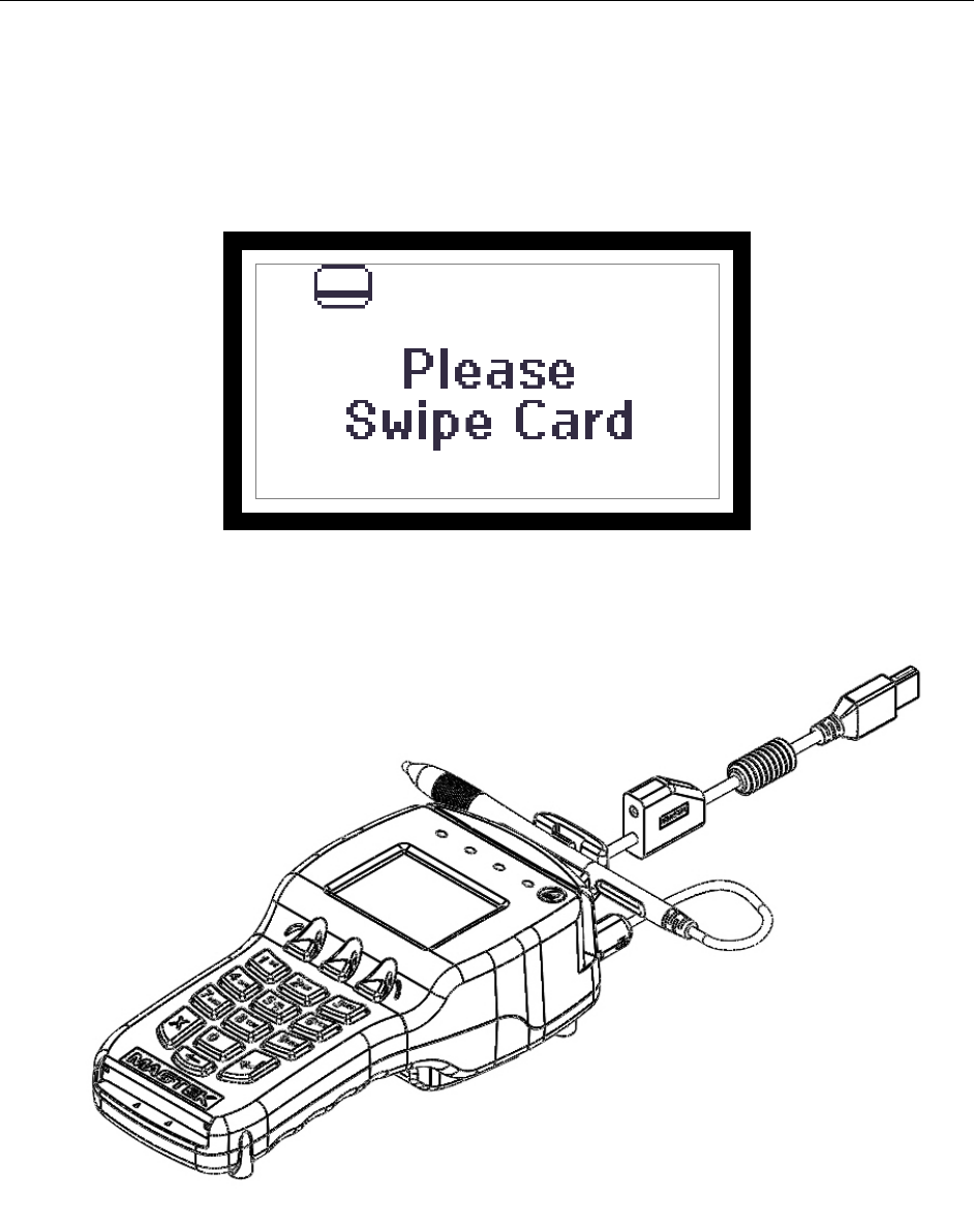
When the appropriate prompt appears (see Figure 4-2 for an example), swipe the card with the
magnetic stripe down and facing toward the keypad of the DYNAPRO as indicated in Figure 4-3
below. If the magnetic stripe data could not be read, the application may prompt the user to
swipe the card again.
Figure 4-2. Example of Swipe Card Screen
Figure 4-3. Swiping a Card Through the DYNAPRO
Operation
15
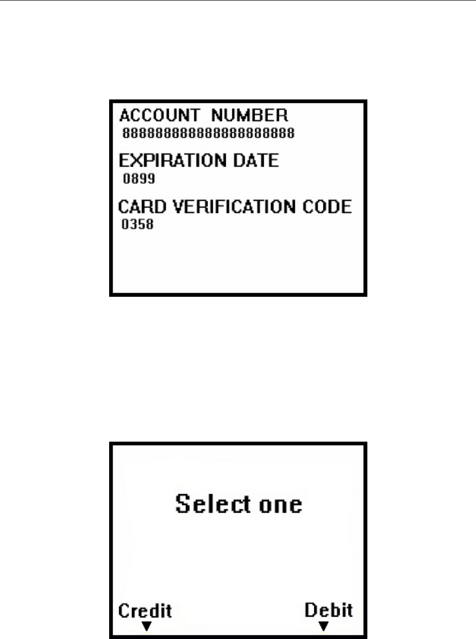
MANUAL CARD ENTRY
If the swiped card’s magnetic stripe is damaged or unreadable, the application controlling the
DYNAPRO may prompt the cardholder to enter information from his or her card manually, as
shown in the following example:
Figure 4-4. Example of User Screen to Manually Enter Card Data
The account number field has a minimum of 16 and a maximum of 19 digits. Expiration date
consists of 4 digits. The card verification code can be 3-4 digits in length.
SELECTING THE CARD TYPE
In a retail setting, the transaction might require the user to select the card type (e.g. “Debit or
Credit”). In the following example, the application prompts the user to press the Left function
key if the card is a Credit card or to press the Right function key if the card is a Debit card:
Figure 4-5. Example of User Screen to Select Card Type
DYNAPRO Installation and Operation Manual
16
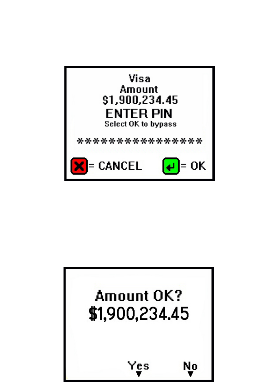
PIN ENTRY
When PIN entry is required, the LCD will prompt the cardholder to enter his or her PIN (the PIN
field has a minimum of 4 and a maximum of 12 digits for PIN entry) as required by the financial
institution (see figure 4-6 for a sample LCD display). After the cardholder has entered a PIN, the
ENTER key must be pressed.
.
Figure 4-6. Example of User Screen to Enter PIN
If the double PIN entry option is enabled, the LCD will prompt the cardholder to reenter his or
her PIN for confirmation. The user must repeat the above process and enter the correct PIN a
second time, followed by the ENTER key.
AMOUNT VERIFY
In a retail setting when the customer selects “Credit” they are then prompted to verify the amount
of the transaction. The customer can select “Yes “or “No” as shown in the following example:
Figure 4-7. Example of User Screen to Verify Amount
Operation
17
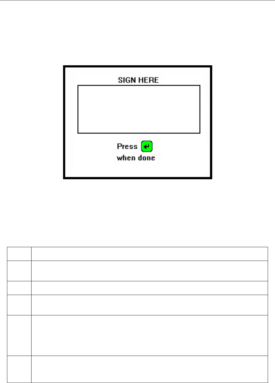
SIGNATURE CAPTURE
If your DYNAPRO has signature capture capability, the LCD will prompt the cardholder to enter
a signature to complete the transaction (see figure 4-7 for a sample LCD display). After the
cardholder has entered his or her signature, the ENTER key must be pressed.
Figure 4-8. Example of User Screen to Enter Signature
STATUS CODES
The Device Offline screen indicates that the device is not ready for normal operation. There is
also a code in the lower right corner that can help explain the cause of the offline state. Codes
that start with H, S, C, or K indicate a problem with the unit that will require the device to be
returned to the supplier for service or replacement.
Code
Type Description
A An offline code beginning with "A" indicates the device is awaiting authentication. This is
a normal condition when a unit configured to require authentication (security level 4).
Authentication by the host application is required to return it to the "Welcome" screen.
C An offline code beginning with "C" indicates the device is missing a certificate. It is
recommended that the device should be repaired or replaced.
H An offline code beginning with "H" indicates there is a hardware problem with the device.
Should any H code be presented, it is recommended that the DYNAPRO be repaired or
replaced.
K
An offline code beginning with "K" indicates a problem with either the MSR or PIN key. If
it is a new device, it is likely due to the PIN Key not being loaded. A new device showing
this code should be returned to the supplier for Key loading. If the code appears after
being deployed and used for a long period of time, this code would be presented if one or
both DUKPT keys have been exhausted. If this is the case it is recommended that you
contact the supplier for a replacement.
S
An offline code beginning with "S" indicates a security element failure. This code can be
triggered through severe handling of the device or strong interference by a nearby EMF
source. If you move the device away from any suspected EMF source and the error
continues, the device should be repaired or replaced.

18
SECTION 5: MAINTENANCE
CLEANING
Periodic cleaning of the DYNAPRO’s exterior may be required. To clean the outside of the
DYNAPRO, wipe down the unit with a soft, damp cloth and then wipe with a dry cloth.
Caution
To avoid damaging the read head, do not touch the inside of the card path with a
wet cloth.
ADJUSTING THE LCD
If it becomes necessary to adjust the LCD brightness or contrast, press the Left function key,
followed by “523” (corresponding to the letters “LCD”), followed by the Right function key.
The LCD will display the following screen:
Figure 5-1. Adjusting the DYNAPRO’s LCD
Once the above screen has displayed, press 1 to decrease, or 3 to increase, the brightness. Press
4 to decrease, or 6 to increase, the contrast.