Maiden Rock Communications MRC565-40-43 Packet Data Radio Transceiver User Manual OPERATION AND MAINTENANCE
Maiden Rock Communications,LLC Packet Data Radio Transceiver OPERATION AND MAINTENANCE
UserManual.wiki
>
Maiden Rock Communications
>
MRC565 40 43 User Manual
Users manual
Navigation menu
Upload a User Manual
Namespaces
Wiki Guide
HTML
PDF
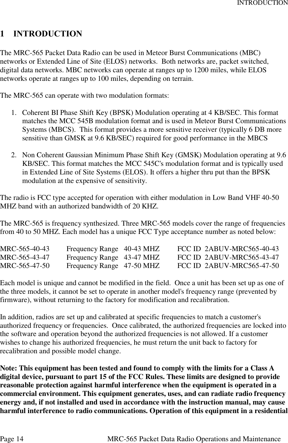
Info
Views
User Manual
Discussion / Help
Navigation

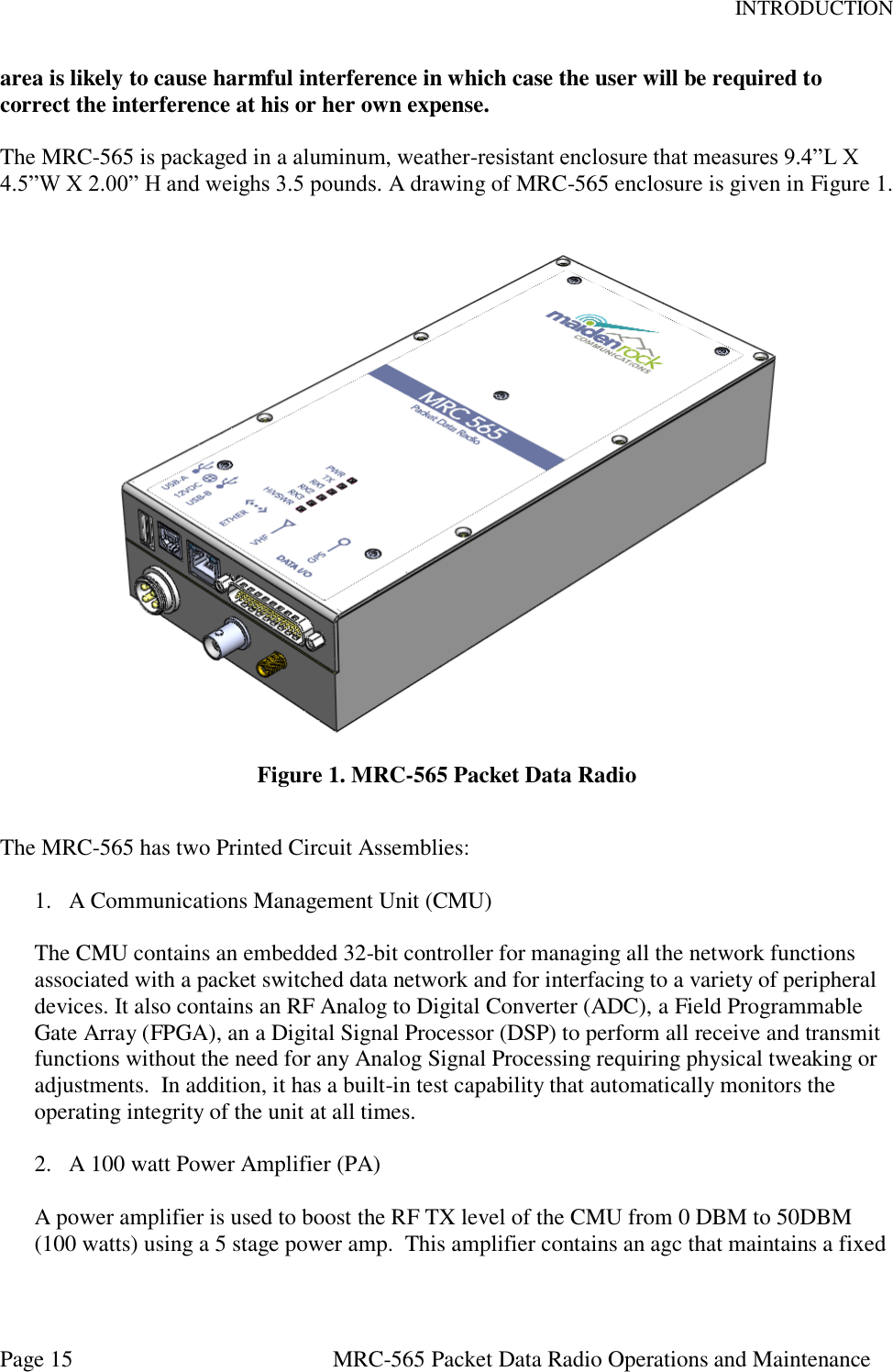

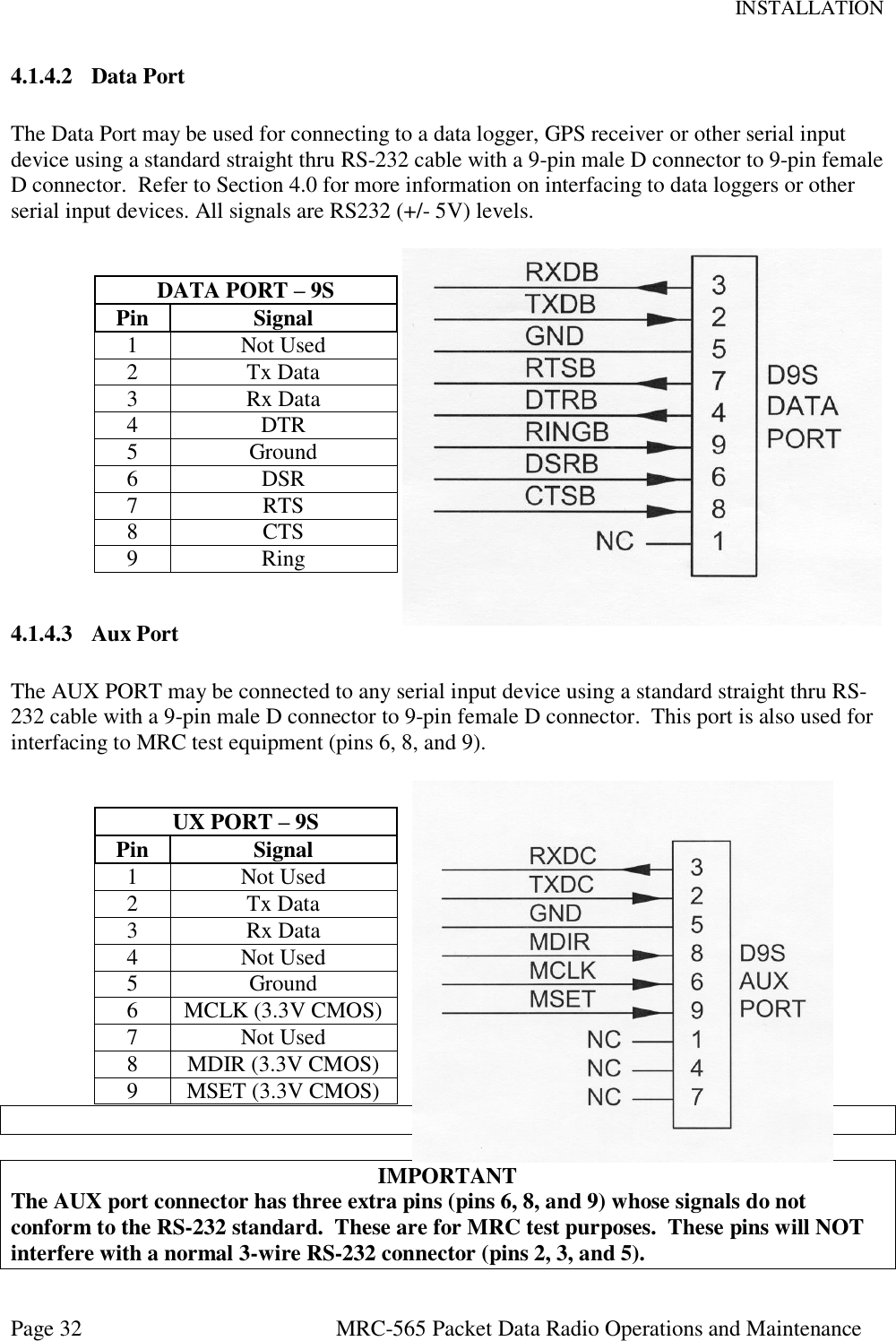
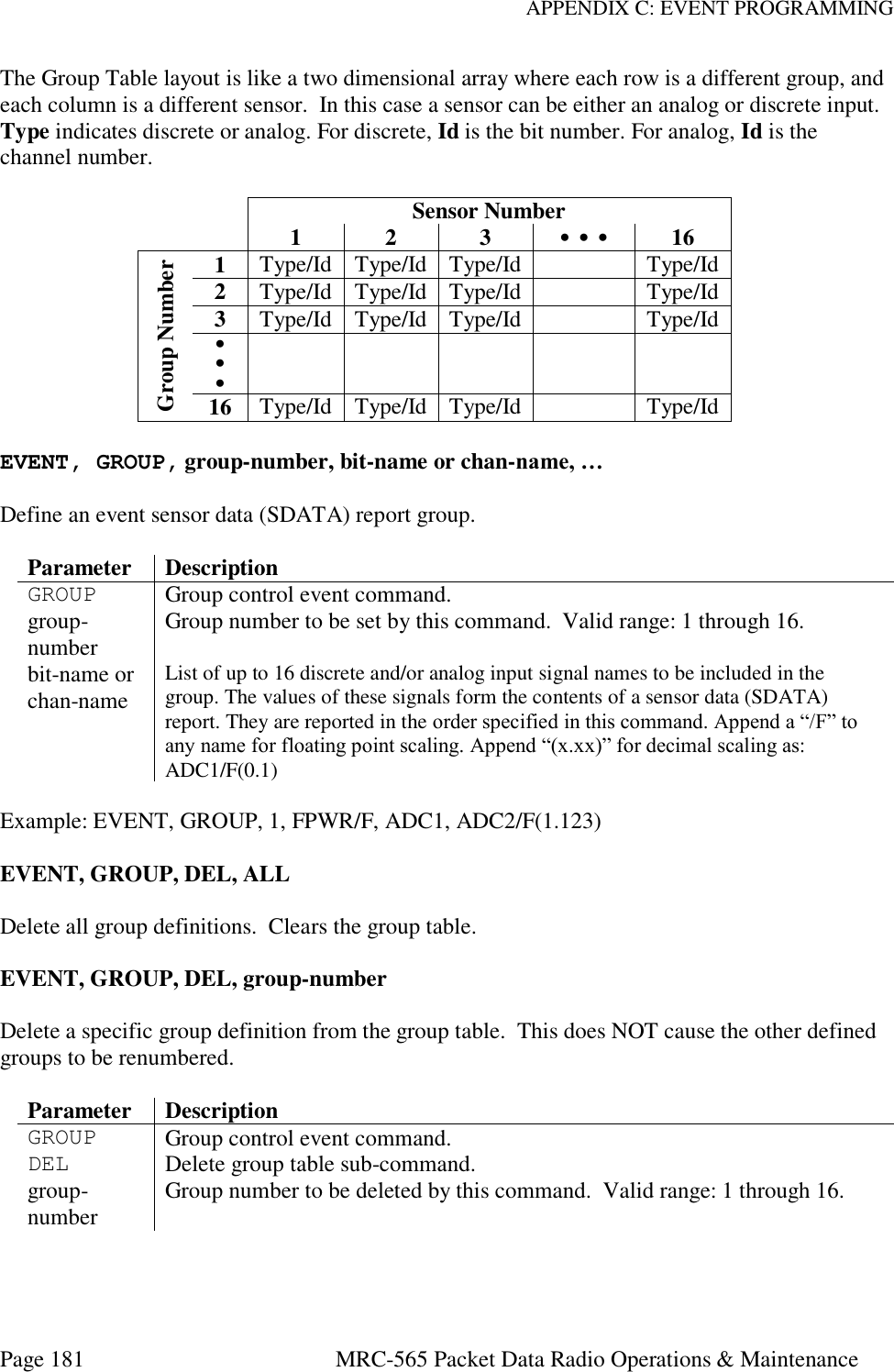
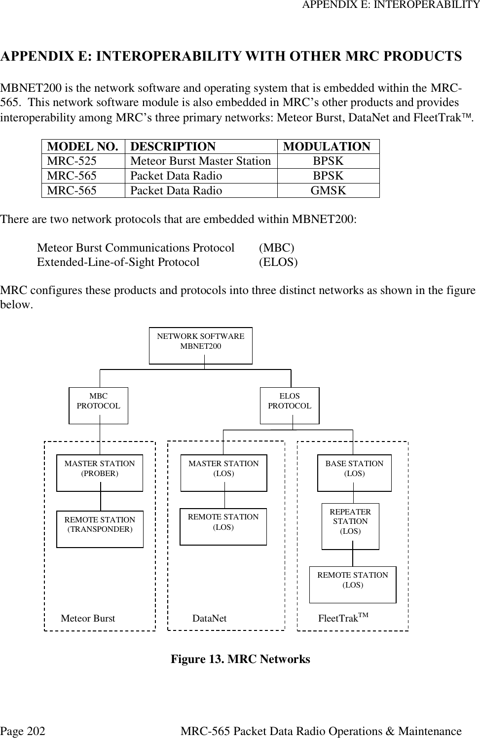
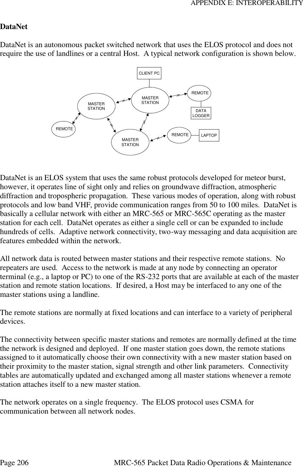
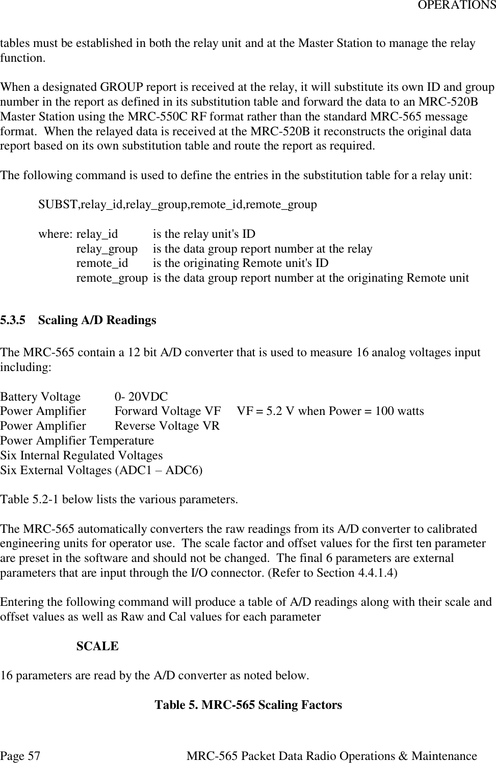
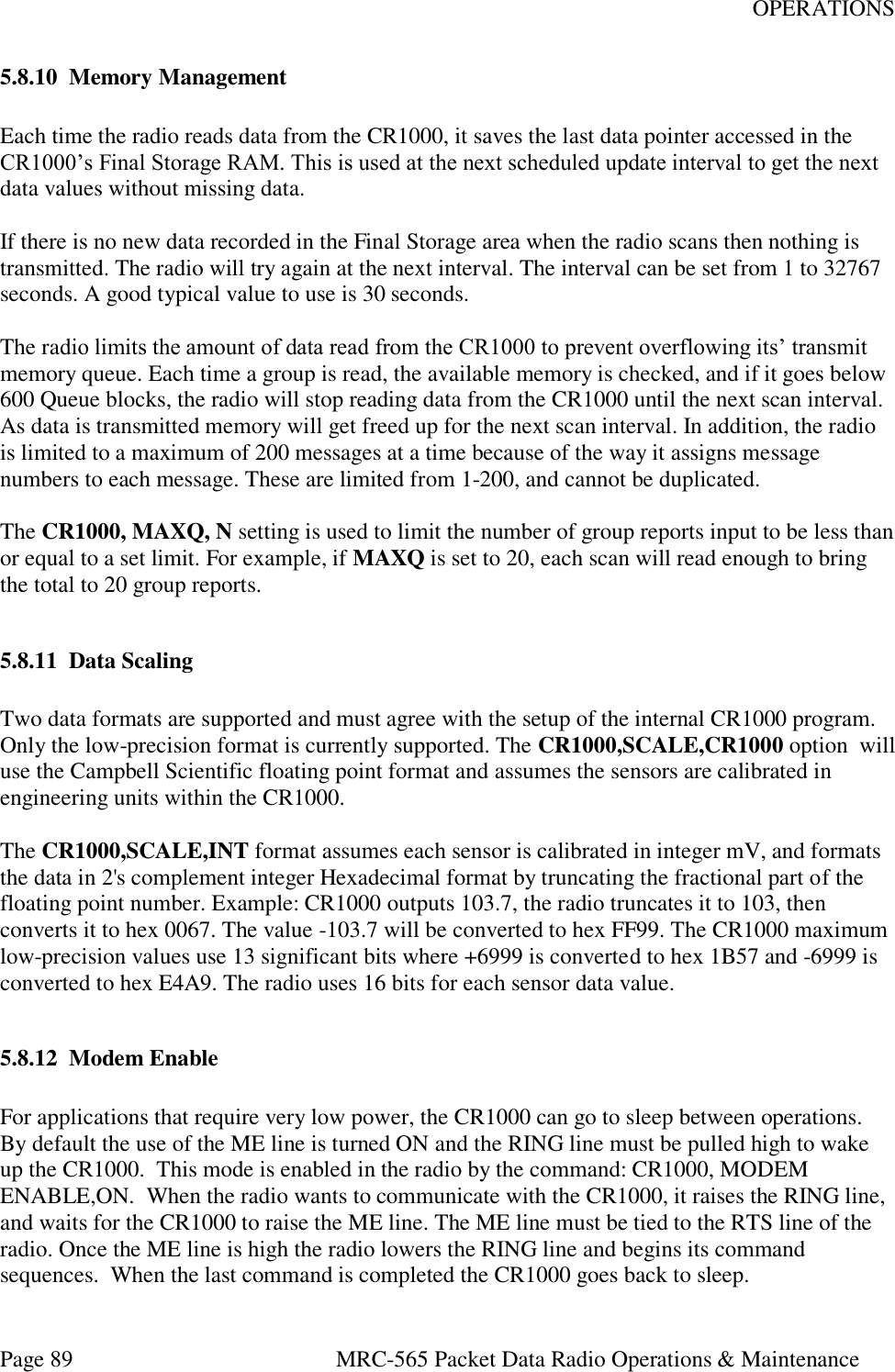
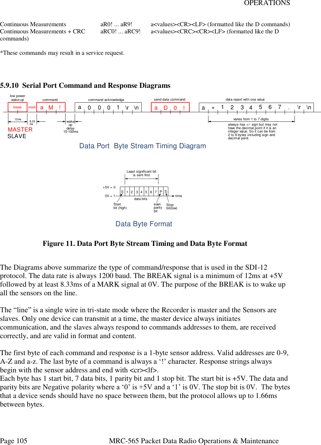
![INSTALLATION Page 36 MRC-565 Packet Data Radio Operations and Maintenance With the exception of the CPLD, all versions of software can be updated via the Operator Port. The CPLD requires direct connection of the Altera Blaster to the board. 4.3 Description of Critical Device Parameters for a MB Network Most of the parameters used in a MB network do not have to be changed from there Factory Defaults for normal operation. However, a few critical parameters must be set to obtain proper operations. These are described below. These commands should be included in the SCRIPT file used to program the unit as described in Section 4,4 below. 4.3.1 Device The MRC-565 can be programmed to operate as a REMOTE, BASE, or MASTER. To check the Device Type enter the following command: DEVICE [ENTER] If the device is not a REMOTE and you want to change it to a REMOTE enter DEVICE,REMOTE [ENTER] SAVE [ENTER] SAVE stores the Device type into FLASH memory. The MRC-565 is always a REMOTE device in a MBC network. It may be any of the three types in an LOS network. 4.3.2 Role ROLE is used to set the Operating Mode and the RF Protocol for the device. There are four modes: PROBE Used if device is set up as a Master Station TRANSPOND Used if device is a Remote Station in a MBC network SILENT Used if device is set up to listen only (No Tx) LOS Used if device is set up as a Remote Station in a LOS network To determine the operating ROLE for the device type the following command: ROLE [ENTER} In a MBC network, the Role for all remotes is defined with the following command: ROLE,TRANSPOND,High #,LOW#,MB for auto MB/LOS select.](https://usermanual.wiki/Maiden-Rock-Communications/MRC565-40-43/User-Guide-2352454-Page-36.png)
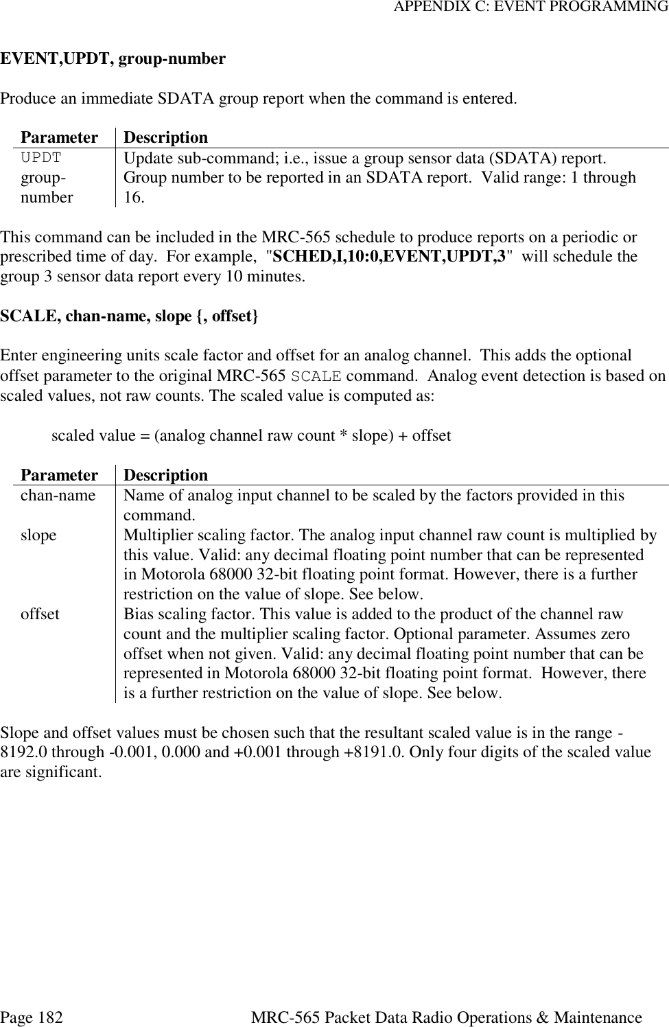
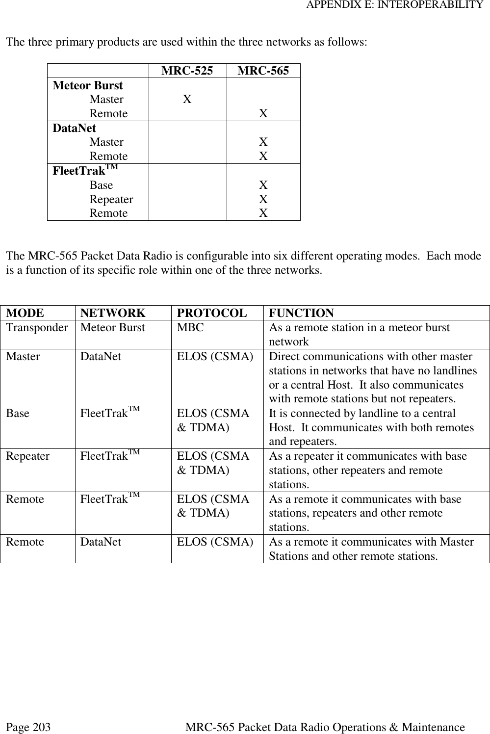
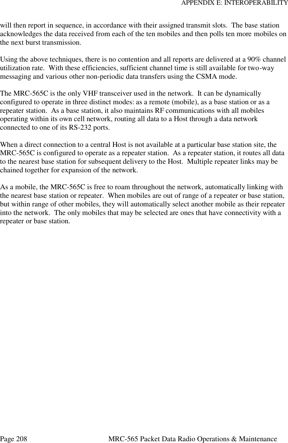
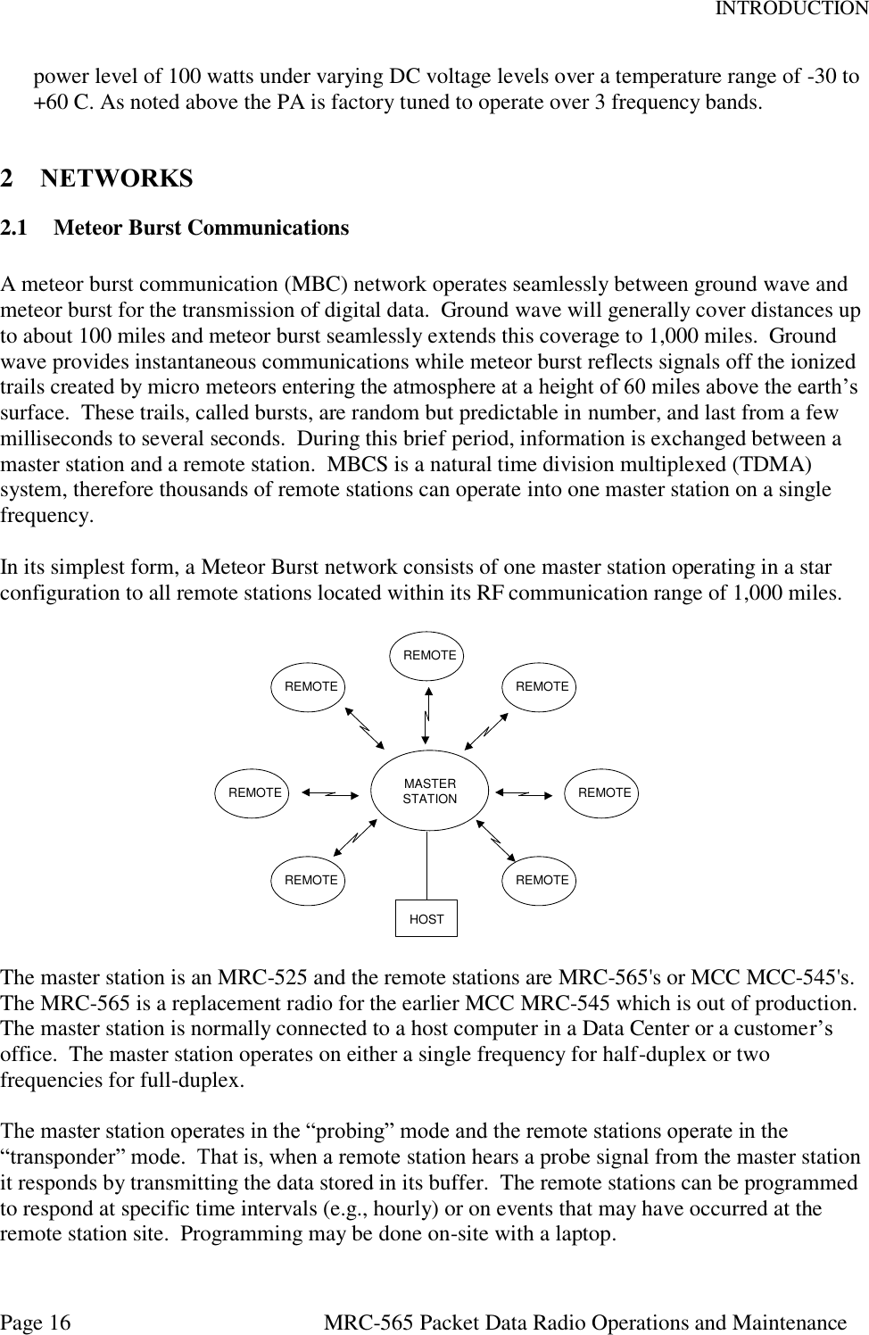
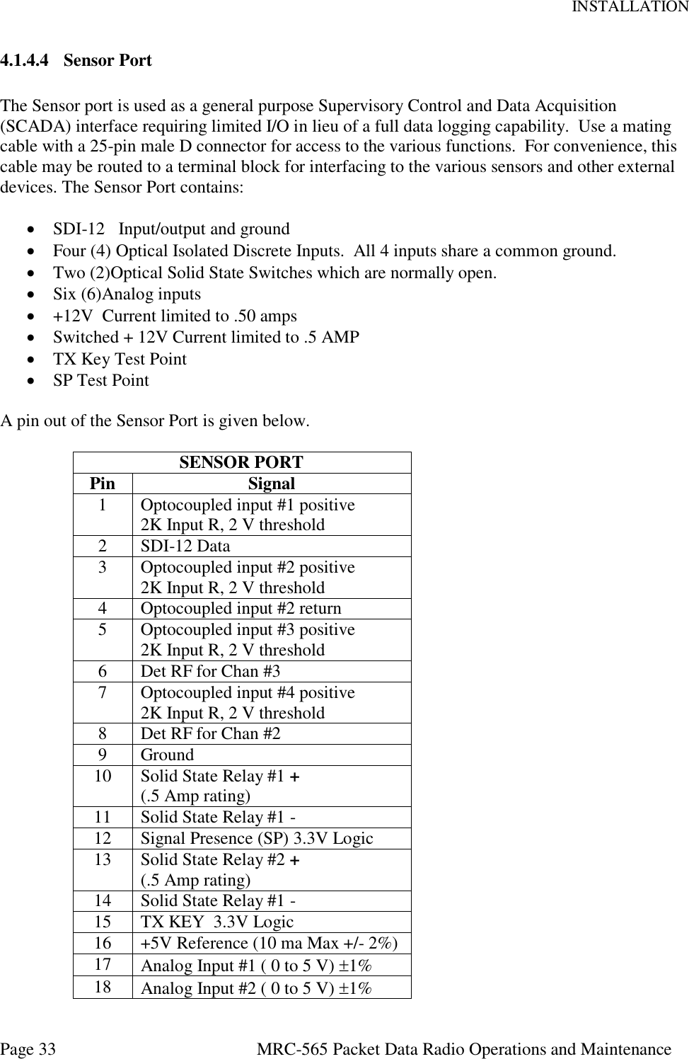
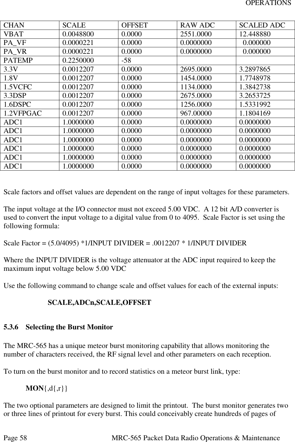
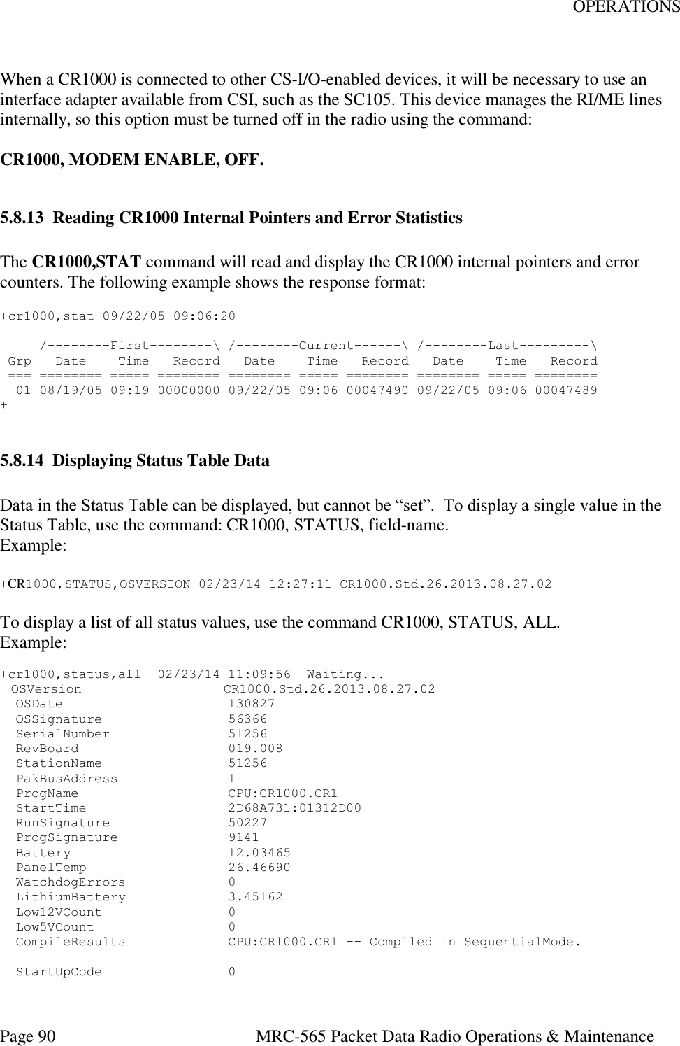
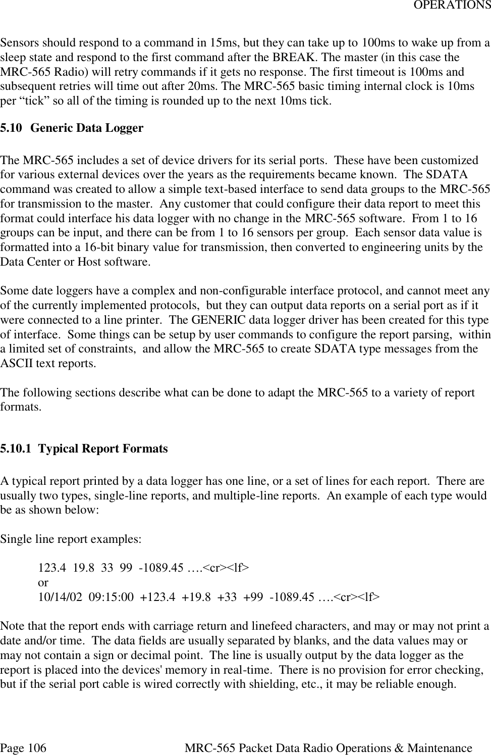
![INSTALLATION Page 37 MRC-565 Packet Data Radio Operations and Maintenance ROLE,TRANSPOND,MB for MB only In the MB mode, the remote will respond to every idle probe from the Master and Transmit if it has data to send Data or its time for it to check in. When a Remote station is close to a Master station (<60 miles) the unit will probably hear the Master station IDLE probe continuously. To prevent the Remote from responding to every Idle probe (which occur about every 25 msec) the unit will automatically switch to a LOS mode. In the LOS mode, the remote will not respond to every Idle probe, but will respond to every N probes, where N is a Random number. The Random number prevents multiple remotes that are operating LOS to the Master from interfering with each other. Note that LOS mode is not the LOS protocol used in Line of Site only network. The two numbers in the ROLE command are used to determine when a remote unit will switch operation between MB and LOS. The high number is the number of Idle probes received per minute it takes to switch from MB mode to LOS mode. The low number is the number of Idle probes received per minute it takes to switch back to MB mode. The defaults settings for these numbers is: HIGH = 100 LOW = 50 Note that since the IDLE probes occur every 25 msec, there are 40 Idle probes per minute, so it would take about 2 ½ minutes to switch to LOS protocol when default settings are used. 4.3.3 Radio ID Number Every unit in a Meteor Burst Communications System has a 16-bit ID. This allows up to 65,536 unique ID numbers. The MRC-565 ID number will already be programmed into the unit by MRC prior to shipment. Enter the command ID [ENTER] and the unit ID number will be displayed on the operator terminal. Contact your System Administrator to register this ID in the network configuration database. In some cases this number will be “locked” and cannot be changed in the field, you can type LOCK to determine if the ID is locked or not. Under some circumstances, the ID may have to be changed on-site. It can only be done if the ID is not locked. In that event, this action must be coordinated with both MRC and your System Administrator. Failure to do so may result in data or messages being misrouted or lost. To change the ID use the following command: ID,nnnnn,mmmmm{,aaaaaa},INIT [ENTER] where nnnnnn is the unit ID, mmmmm is the master station assignment and aaaaaa is the master select mode (FIXED, AUTO, PREF, MULTI). Obtain the proper master station](https://usermanual.wiki/Maiden-Rock-Communications/MRC565-40-43/User-Guide-2352454-Page-37.png)
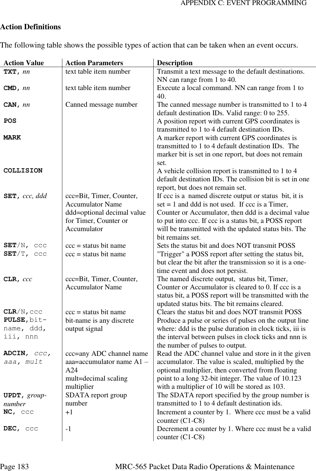
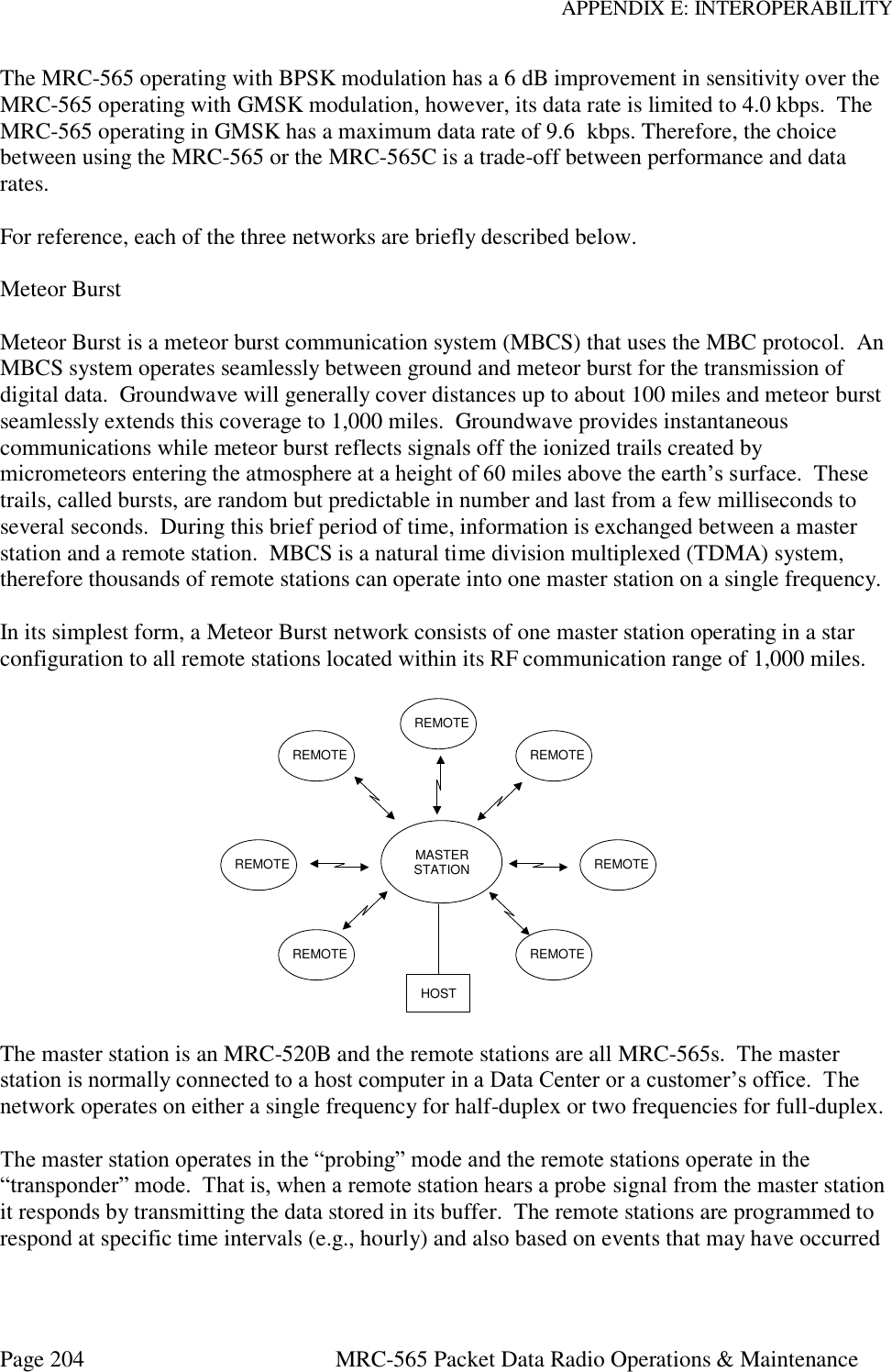
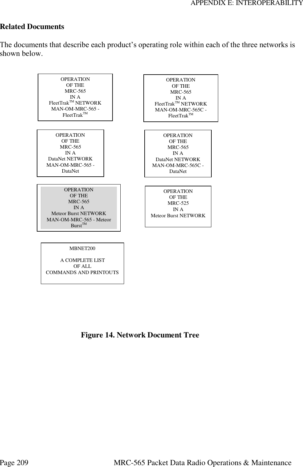
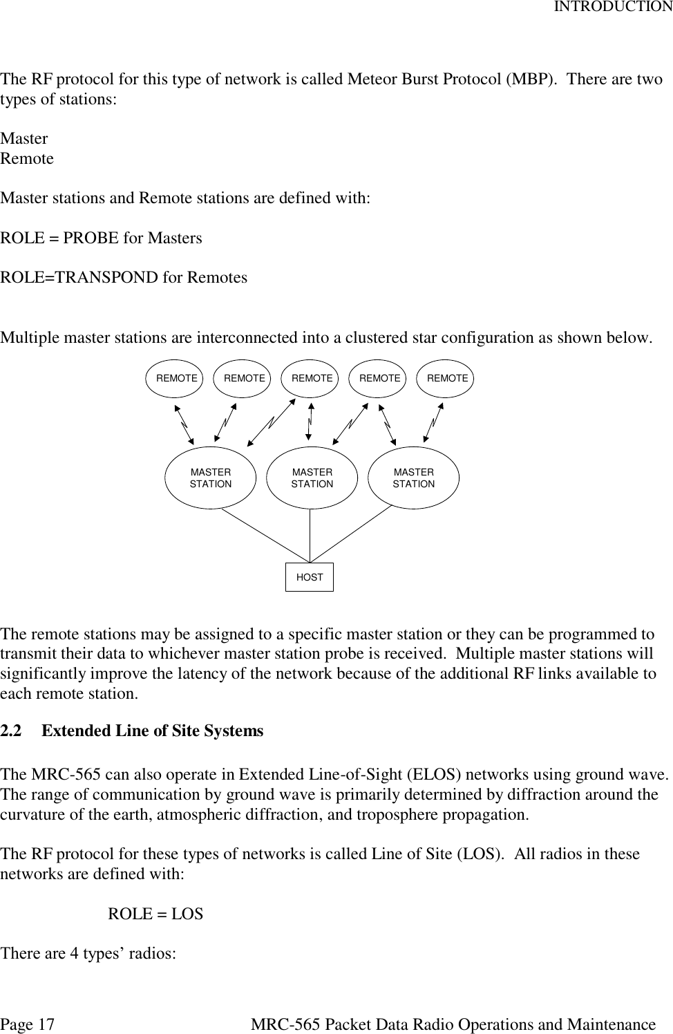
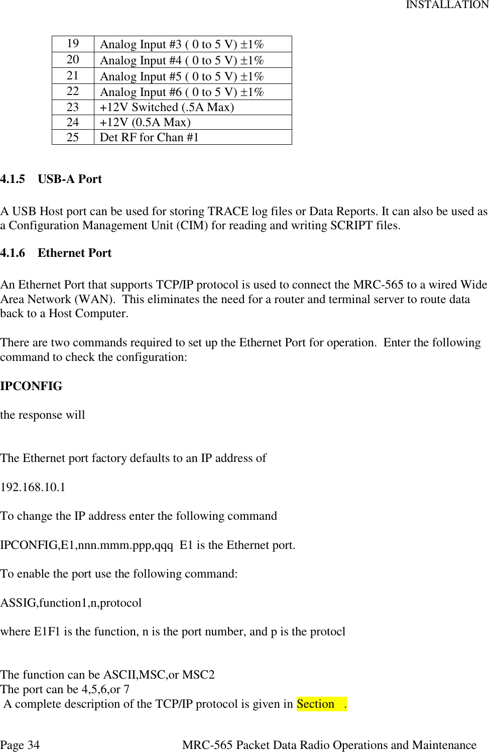
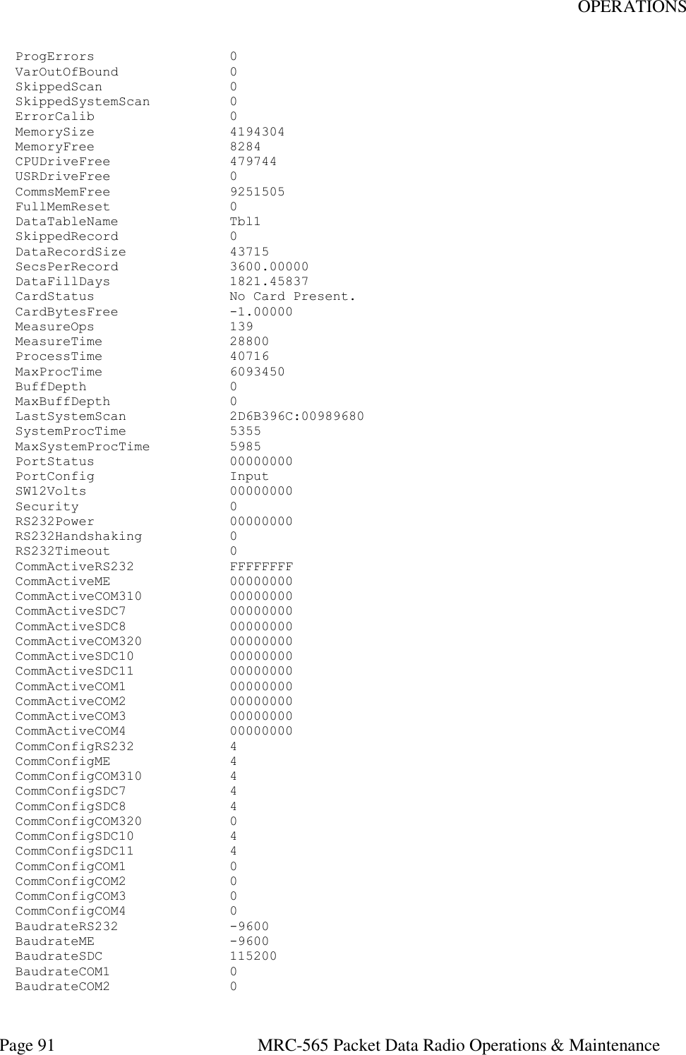
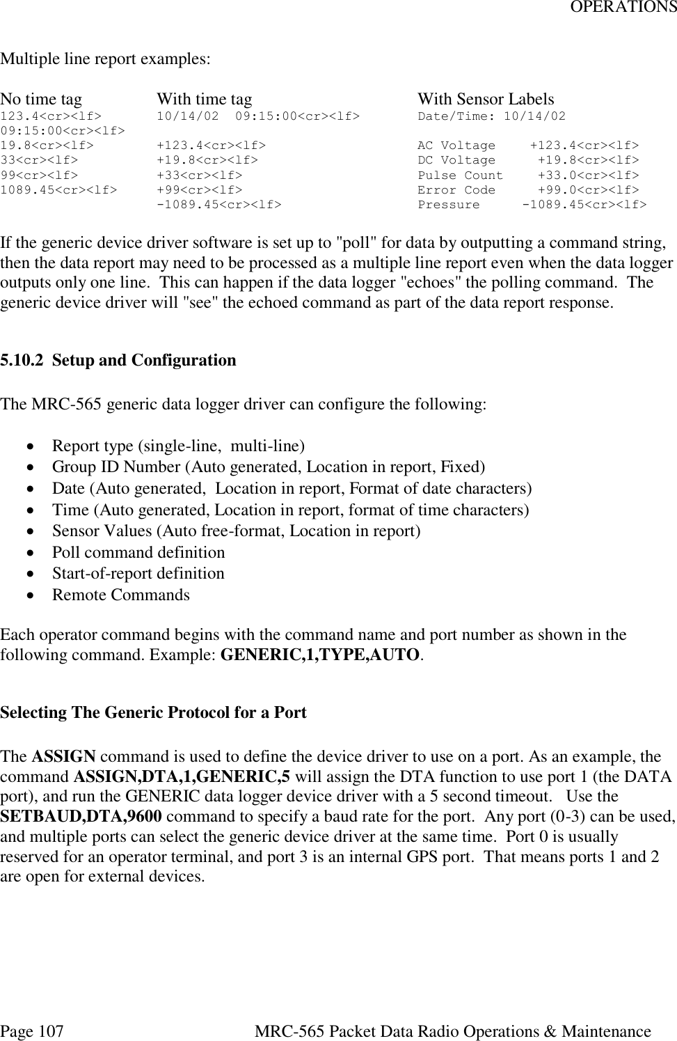
![INSTALLATION Page 38 MRC-565 Packet Data Radio Operations and Maintenance assignment and select mode from your System Administrator. The MRC-565 will save this ID and will use it whenever the unit is powered up or reset. MODE DESCRIPTION PREF Unit connects to the mmmm Master for the NDOWN period (set with SNP command). After NDOWN period unit will connect to the Master that it has received the most syncs from. In this mode the unit can communicate with only one Master at a time. AUTO Unit connects to the mmmm Master, if it’s not successful it switches to another Master. It will stay with that Master as long as it can communicate with it. In this mode the unit can communicate with only one Master at a time. This is the preferred mode for LOS networks FIXED Connectivity will be fixed to the mmmm Master. In this mode the unit can communicate with only one Master at a time. This is the preferred mode for networks with a single master. MULTI In this mode the unit can connect to any multiple Masters, This is the preferred mode for Meteor Burst Networks. The format for this mode is: ID,nnnnn,1,MULTI,INIT [ENTER] You can also change the mode for the ID by typing ID,aaaaaa 4.3.4 Frequency and Modulation Parameters The MRC-565 will already be programmed with the authorized frequencies to be used in your network. These frequencies are stored in parameter memory and cannot be changed. Verify that the correct frequency is configured by entering the command: CHANNEL (cr) This will show you the “Active” TX and RX Frequency pair and frequency pairs for up to 20 channels that were programmed at the factory. The following table will be displayed for the SNOTEL network: +CHANNEL 01/01/00 01:08:29 Primary Channel TX mhz RX mhz Mod-Val Bit rate Modulation 07 41.6100 40.6700 1 4K bpsk25 Channel Table: Channel TX mhz RX mhz Mod-Val Bit rate Modulation](https://usermanual.wiki/Maiden-Rock-Communications/MRC565-40-43/User-Guide-2352454-Page-38.png)
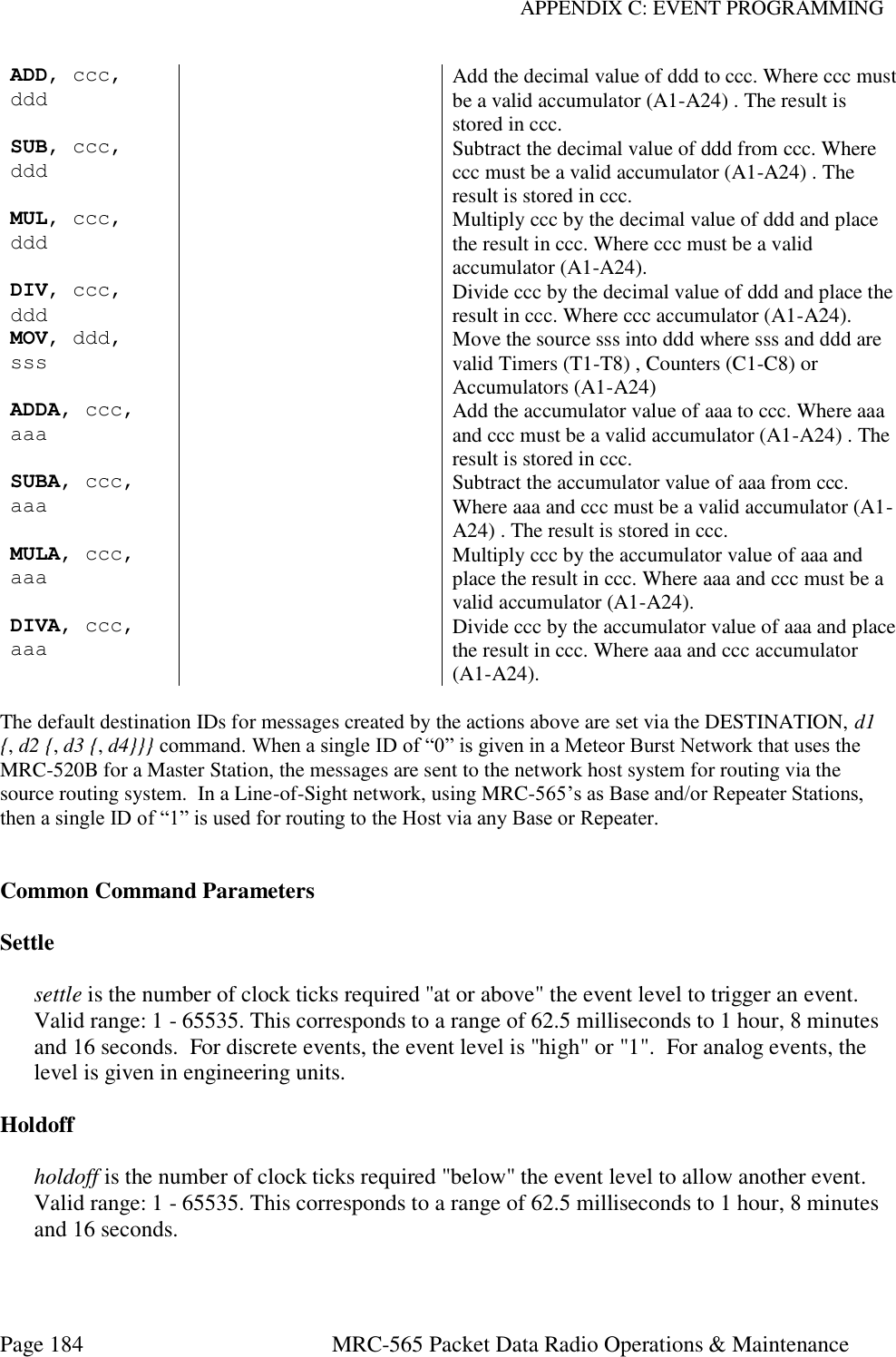
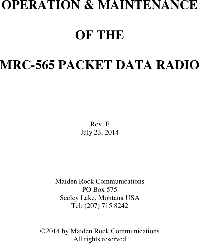
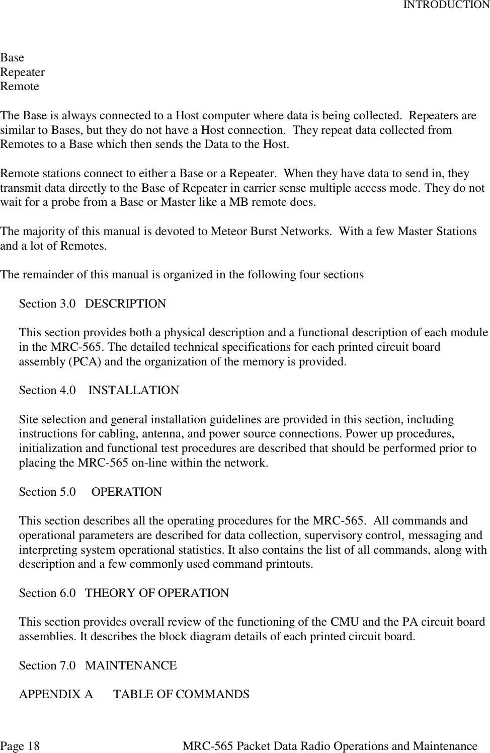
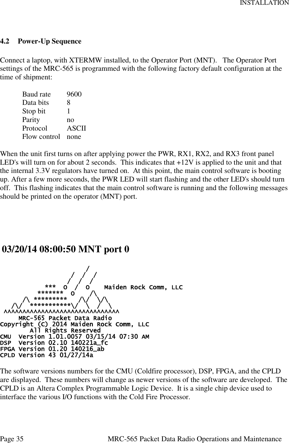
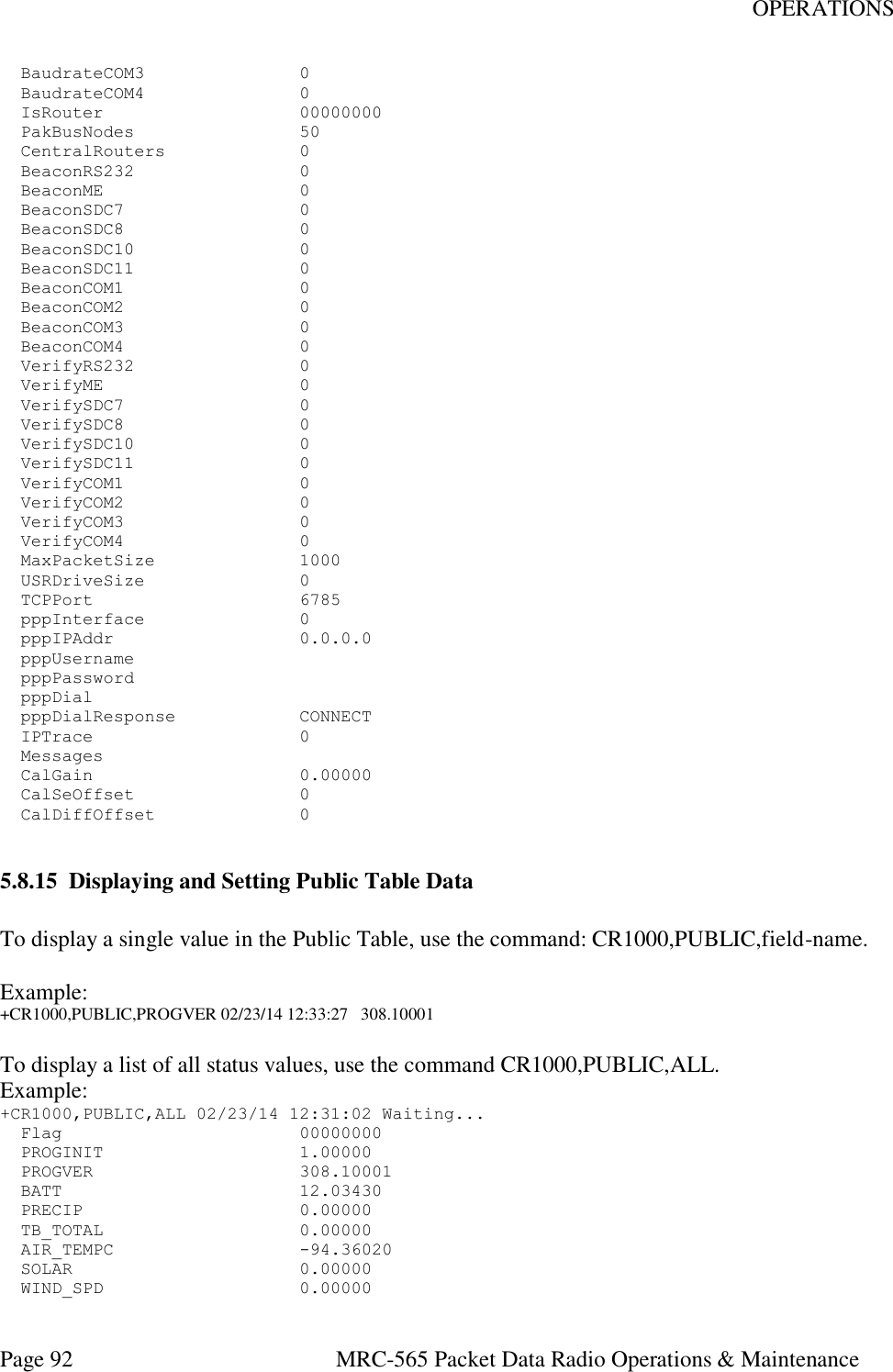
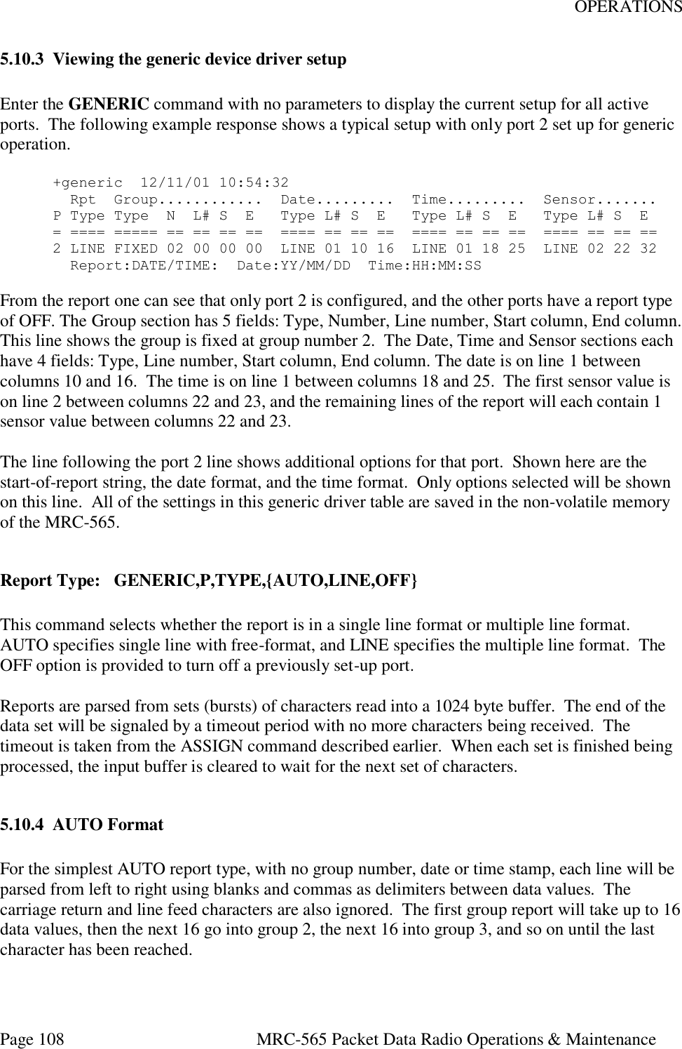
![INSTALLATION Page 39 MRC-565 Packet Data Radio Operations and Maintenance 00 40.5300 41.6100 1 4K bpsk25 01 41.5300 41.5300 1 4K bpsk25 02 40.5300 41.5300 1 4K bpsk25 03 41.5300 40.5300 1 4K bpsk25 04 40.6700 40.6700 1 4K bpsk25 05 41.6100 41.6100 1 4K bpsk25 06 40.6700 41.6100 1 4K bpsk25 >07* 41.6100 40.6700 1 4K bpsk25 08 41.6100 40.5300 1 4K bpsk25 09 41.5300 40.6700 1 4K bpsk25 + You can select any frequency pair from the frequency table by entering the following commands: ASSIGN,RX1,n Where n is the channel number you want to assign to RX1. CHANNEL, n Where n is the desired channel number For example: To select channel 7 above enter: ASSIGN,RX1,7 CHANNEL, 7 The active channel is the one with > in front and * after the channel number, 07 in this case. The table above shows all the assigned channels and is Locked into each MRC radio before it leaves the factory. Operation on channels beyond those listed is not possible without sending it back to the factory for reprogramming. 4.3.5 Select Site Name A descriptive name may be given to the site where the MRC-565 is being installed. The selected site name must be coordinated with your System Administrator. To enter a site name use the following command: SITE NAME, XXXXXX [ENTER] where XXXXXX may have a maximum of 32 alpha-characters. 4.4 Enter Script Files The MRC-565 must be programmed with the parameters that “fit” the network that it is being used in. This programming is accomplished by loading “Script file” from your PC into the MRC-565 using the Operator (MNT) port. The Script File can also be downloaded into a Remote Station via RF from the Master Station.](https://usermanual.wiki/Maiden-Rock-Communications/MRC565-40-43/User-Guide-2352454-Page-39.png)
![INSTALLATION Page 40 MRC-565 Packet Data Radio Operations and Maintenance If a script file have not been programmed into the MRC-565 and it must be changed, a new file can be loaded from your operator terminal using XTERMW software. One script file uniquely programs the MRC-565 to operate as a remote station in your specific network. Other script files define application programs that are performed by the station. For example, the application for a remote station may be as a mobile unit reporting position data or as a fixed site reporting sensor data. The procedure for loading the script file is described below: 1. Install the MRC-565 Meteor Burst CD (or diskette), with the script file on it, into your laptop or equivalent, and load the script file into your XTERM subdirectory. 2. Start XTERMW and open a connection at the correct baud rate and COM port (typically COM1, 9600 baud. All other parameters are defaults. 3. Type “factory,default,init” to load the default parameters into the MRC-565. The MRC-565 has a very large Flash memory for storing station parameters, as such it takes longer (90 seconds)to erase than it does to erase the MCC 545 flash memory (30 seconds) 4. Choose “Execute Script” from the “scripts” pull down menu. 5. Select the appropriate script file in the XTERM subdirectory. Double click the file name to start execution. The commands in the script file will be executed one at a time until the end of the file is reached. Press the “up arrow” key to scroll up and review the command responses. If any commands result in BAD COMMAND, BAD PARAMETER, or similar message, the script file may have an error in it. You may verify that the correct configuration file has been loaded by entering the three commands: ASSIGN, SNP, and CONFIG. A typical script file for a remote operating in a MBC network connected to a CR10X Data Logger is given below.) IMPORTANT The SAVE command must be performed at this time. Failure to do so will result in the loss of any new configuration data in RAM that you may have entered during initialization. The CONFIG command may be used to confirm that the MRC-565 has been configured correctly for the network it is operating in. For example, if your MRC-565 is being used in a Meteor Burst network the following configuration parameters will be displayed on your operator terminal when you enter CONFIG [ENTER]. DATE 2/17/14 TIME 13:58:16](https://usermanual.wiki/Maiden-Rock-Communications/MRC565-40-43/User-Guide-2352454-Page-40.png)
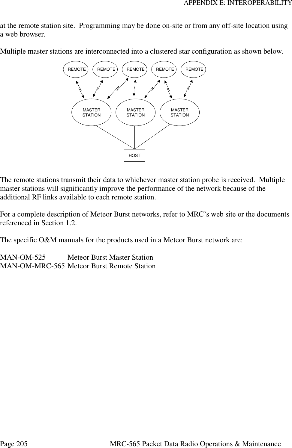
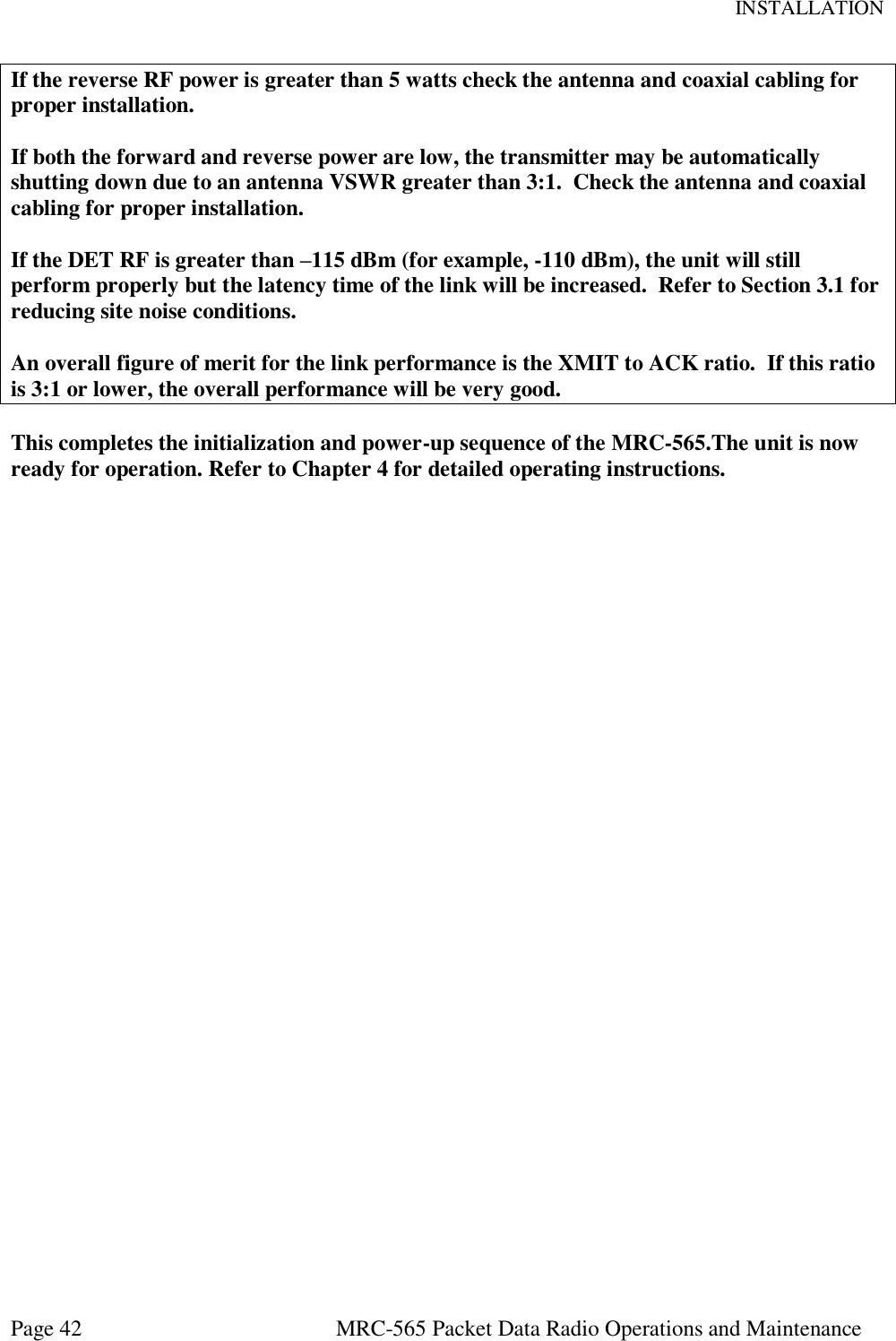
![INSTALLATION Page 41 MRC-565 Packet Data Radio Operations and Maintenance DEVICE TYPE REMOTE ROLE TRANSPOND,100,50,MB ID 00500,00001,MULTI DEFAULT DEST. 0 MODULATION BPSK25 TRANSMIT KEY STARTED BIT RATE 4K MESSAGE HOLD OFF DUPLEX MODE HALF DUPLEX SCHEDULE ACTIVE or EMPTY SERIAL 1 TX LIMIT 200 CHECK IN 900 STAT RPT INT. 24 LOS CHECKIN 5 DUTY CYCLE 10% LOS RETRY 2 POS 30,TXT,NMEA POLL OFF SOURCE RELAY OFF BASE 0,0 REPEATER OFF PULSE OFF POSRPT OFF HOURLIES ON NETMON ON ENTEK MDP OFF RCT OFF RXTYPE MRC-565 REMOTE TYPE COMM SUBST OFF SCALE B: 0.062500, D: 0.018800, T: 0.000353 MAINTENANCE CONSOLE DEVICE 4.5 RF TEST A very thorough RF test can be made by entering the command TEST [ENTER]. TEST causes the processor to turn the transmitter ON and measures the forward and reverse RF power that is being transmitted. It also measures the battery voltage under load and the antenna noise voltage. The following response will be displayed on the operator terminal: Syncs Xmits Acks pwr-fwd pwr-rev v-bat det-rf resets XXXX YYYY ZZZZ AAAA BBBB CCC DDD EEE where: XXXX = # of sync patterns received from the master station. YYYY = # of transmissions made by the MRC-565. ZZZZ = # of Acknowledgements received from the master station. AAAA = Forward power in watts. This should be greater than 80 watts. BBBB = Reflected power in watts. This should be less than 5 watts. CCC = Battery voltage under load (while transmitting). This should be greater than 10.6 VDC. DDD = Received signal strength in dBm. This will normally be the noise level at the antenna and should read about –120.. EEE Number of times the radio has rebooted. NOTE The forward RF power should be at least 80 watts if the battery voltage is normal. If it is lower than 80 watts check for proper cabling to the power source. (see Section 3.2.2.1).](https://usermanual.wiki/Maiden-Rock-Communications/MRC565-40-43/User-Guide-2352454-Page-41.png)
![OPERATIONS Page 44 MRC-565 Packet Data Radio Operations & Maintenance 5 OPERATIONS This chapter covers the basic operating procedures for the MRC-565 as it's used in a Meteor Burst network. The MRC-565 is programmed using Script Files that contain the specific system parameters for operating in the meteor burst mode. These are loaded into the MRC-565 at the MRC facilities prior to shipment. The script files may also be loaded and/or modified at the customer’s site. You should always reset to factory default parameters by typing FACTORY,DEFAULT,INIT prior to loading any new script files. It is assumed at this point that the appropriate script file has already been loaded into the unit, as part of the installation procedures outlined in Section 4.0, and that the unit is configured properly and operational within its network. This chapter describes the various commands that are available to the operator for modifying the station configuration parameters to accommodate specific applications, sending and receiving messages and interfacing to peripheral devices for data collection and supervisory control. 5.1 Getting Started 5.1.1 Command Entry and Editing You must enter carriage returns after every command. A list of all the operator commands are given in Appendix B When a command is accepted, the operator terminal will print the system time. Before you begin you should familiarize yourself with the special editing functions that you can use when entering commands: [DEL] Deletes last character entered. [CTRL] Prints command line on next line down. [CTRL]-R Repeats last command line \X Removes current line from command buffer. [CR], [LF] or [ENTER] Terminates line and causes the command entered to be executed.](https://usermanual.wiki/Maiden-Rock-Communications/MRC565-40-43/User-Guide-2352454-Page-44.png)
![OPERATIONS Page 45 MRC-565 Packet Data Radio Operations & Maintenance 5.1.2 HELP Command Entering HELP [ENTER] produces a single page display of all the commands used in the operation and maintenance of the MRC-565. To obtain descriptive information about a particular command and how it is used by the MRC-565 enter the command type. For example: HELP, ASSIGN [ENTER]. 5.1.3 System Time and Date The MRC-565 has its own internal clock that is periodically synchronized to the nearest second with the master station. The master station receives the correct date and time from either its Host, GPS, or RTCM broadcast. The master station then periodically broadcasts this date and time information to all remotes for synchronizing their internal clocks. If required, the date and time may be initialized using the following commands: DATE, mm/dd/yy [ENTER] TIME, hh:mm{:ss} [ENTER] In a Meteor Burst network the internal battery that is used to back up the Real Time Clock chip is not installed so time and date must be entered at site whenever power is applied to unit. The internal clock will be maintained during all Low Power Modes. The date and time of day maintained in the Master Station (MRC-525 or the MCC 520B) is transmitted to all Remote Stations between the times of 00:10:00 and 00:50:00 of each day, time keeping all units in a network on the same time reference. If the time of day received at a Remote Station differs by more than two minutes from the internal Remote clock, the Remote will set its clock to the received time of day. To manage time properly, each Master Station and Remote Station must know how its own time zone relates to UTC and the system time. This relationship is established by relating its time zone to known reference points. UTC is always referenced to GMT; however, system time can be referenced to any desired time zone. The time zone offset is defined with the following command: TIME ZONE,UTC, Local Time Offset Always set UTC Offset to 0, the local time offset should be set to the time zone offset (+/- TZ) the remote station is from the master station time zone. 5.1.4 Factory Default Parameters When you type](https://usermanual.wiki/Maiden-Rock-Communications/MRC565-40-43/User-Guide-2352454-Page-45.png)
![OPERATIONS Page 47 MRC-565 Packet Data Radio Operations & Maintenance 2 – 254 Master Station 256 – 4095 Remote Verify the ID is set correctly with the following command: ID [ENTER] If it is not correct, refer to Section 4.3.3 for instructions on how to set it. This will show you the “Active” TX and RX Frequency pair and frequency pairs for up to 20 channels that were programmed at the factory. 5.2.2 Radio Frequencies and Modulation Format As noted in Section 4.3.4 above, the MRC-565 will already be programmed with the authorized frequencies to be used in your network. These frequencies are stored in parameter memory and cannot be changed. Verify that the correct frequency is configured by entering the command: CHANNEL (cr) The following table will be displayed for the SNOTEL network: +CHANNEL 01/01/00 01:08:29 Primary Channel TX mhz RX mhz Mod-Val Bit rate Modulation 07 41.6100 40.6700 1 4K bpsk25 Channel Table: Channel TX mhz RX mhz Mod-Val Bit rate Modulation 00 40.5300 41.6100 1 4K bpsk25 01 41.5300 41.5300 1 4K bpsk25 02 40.5300 41.5300 1 4K bpsk25 03 41.5300 40.5300 1 4K bpsk25 04 40.6700 40.6700 1 4K bpsk25 05 41.6100 41.6100 1 4K bpsk25 06 40.6700 41.6100 1 4K bpsk25 >07* 41.6100 40.6700 1 4K bpsk25 08 41.6100 40.5300 1 4K bpsk25 09 41.5300 40.6700 1 4K bpsk25 + You can select any frequency pair from the frequency table by entering the following commands: ASSIGN,RX1,n Where n is the channel number you want to assign to RX1. CHANNEL, n Where n is the desired channel number](https://usermanual.wiki/Maiden-Rock-Communications/MRC565-40-43/User-Guide-2352454-Page-47.png)
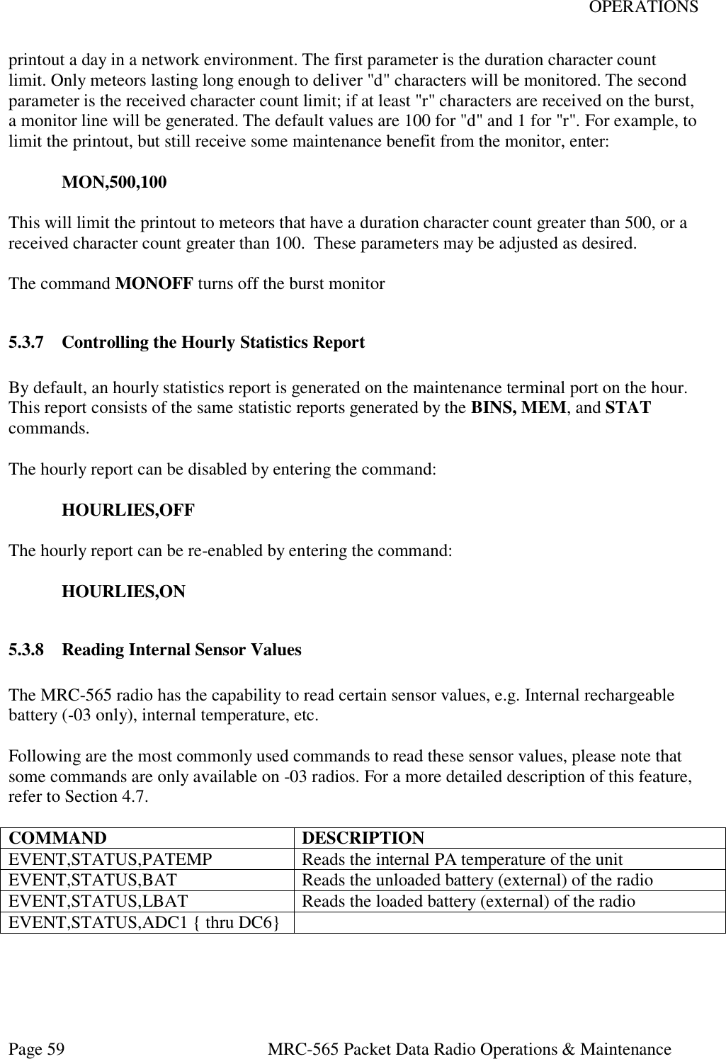
![OPERATIONS Page 63 MRC-565 Packet Data Radio Operations & Maintenance Figure 7. Message Flow and Associated Commands The following operations are explained in this section: SECTION OPERATIONS 5.3.1 Entering and Deleting Messages 5.3.2 Editing Messages 5.3.3 Sending Messages 5.3.4 Sending Commands 5.3.5 Sending Canned Messages 5.3.6 Receiving Messages 5.3.7 Examining Message Status 5.3.8 Examining and Revising Message Queues 5.4.1 Entering and Deleting Messages All messages are composed and edited in the TEXT EDIT BUFFER. Messages may be 3,570 characters in length. When composing the message press [ENTER] at the end of each 80 character line. There is a default destination programmed into the MRC-565 during the installation and initialization of the unit when it is first brought on-line in the network. If a message is not given a specific destination it will be sent to the default destination only. To enter a message: TX QUEUE PRINT RX QUEUE [SHOW] [FLUSH] [DEL] [SMS] [SHOW] [FLUSH] [DEL] [SMS] TEXT EDIT BUFFER [MESSAGE] [REMCMD] [CANMSG] EDIT COMMANDS [ESC] [DEL] [ESC] TO/FROM NEIGHBORING STATIONS ACK END-TO-END ACK](https://usermanual.wiki/Maiden-Rock-Communications/MRC565-40-43/User-Guide-2352454-Page-63.png)
![OPERATIONS Page 64 MRC-565 Packet Data Radio Operations & Maintenance 1. Type MESSAGE. The operator terminal will respond with ENTER TEXT. The MRC-565 will now be in the compose and edit mode. 2. Enter a message up to 3,570 characters in length, pressing [ENTER] at the end of each 80 character line. 3. Press the [ESC] key. The message will now be transferred to a Tx queue and will be automatically transmitted to the default destination at a priority level R. The following message will be displayed, or printed, on the operator terminal: hh:mm:ss Message No: name:ss,nnnn chars, nnn segments hh:mm:ss ROUTING name :sss TXT sss/nn TO: name If you wish to send a message to multiple destinations, and at a different priority level, type MESSAGE, R, dest1, dest2, …dest n where: “R” is any priority level from A to Z. A is the highest and Z is the lowest. “Dest” is the numerical ID of the stations to which the message will be routed. NOTE If you also want to send the message to your default destination you must enter its station numerical ID as one of the destination parameters (“dest1”, “dest2”, etc.) as specified above. Three other special editing functions may be used: 1. To Retransmit the Previously Entered Message To retransmit a previously entered message simply depress the [ESC] key after the operator terminal prints ENTER TEXT and before any other key is depressed. The previous message entered into the TEXT EDIT BUFFER will then be sent to the destinations that are now designated in the MESSAGE command. 2. To Revise the Previously Entered Message To revise a previously entered message press [CTRL]T after the ENTER TEXT prompt to revise a previously entered message or to recover from an aborted session. The previous message will be displayed with the cursor placed at the end of the message. You may now resume editing the message. 3. To Delete a Message To delete a message after it has been placed in the Tx Queue, type](https://usermanual.wiki/Maiden-Rock-Communications/MRC565-40-43/User-Guide-2352454-Page-64.png)
![OPERATIONS Page 65 MRC-565 Packet Data Radio Operations & Maintenance DELMSG, ID: sss where: ID is the numerical station ID sss is the message serial number The operator terminal will print the date and time, followed by MESSAGE DELETED. 5.4.2 Editing Messages The following editing functions may be used from the keyboard while the message is in the TEXT EDIT BUFFER. KEY FUNCTION [DEL] Deletes the last character entered. [CTRL]R Prints the current line of text on the next line down. [CTRL]I Performs a fixed tab function \ Removes the current line from the edit buffer. [ENTER] Performs a carriage return and line feed. [LF] Performs a carriage return and line feed. [CTRL]X Removes the current line from the edit buffer and places the cursor at the end of the previous line. [CTRL]T Prints the contents of the edit buffer & puts cursor at the end of text. [CTRL]D Erases the entire contents of the edit buffer. [CTRK]A Aborts the edit mode and returns to the command mode. A “+” indicates the command mode. [ESC] Leaves text edit mode and queues the message for transmission. 5.4.3 Sending Messages Messages are automatically stored for transmission with the [ESC] key. Each message will be placed in the Tx Queue in accordance with its assigned priority. Messages of equal priority are placed in the Tx Queue in the order received from the TEXT EDIT BUFFER. The following display will appear on the operator terminal as the MRC-565 stores and routes a message: hh:mm:ss Message No: name:ss,nnnn chars, nnn segments hh:mm:ss ROUTING name :sss TXT sss/nn TO: name Messages are transmitted in packets and are routed to their destination in a store and forward manner, using the most efficient routing within the packet switched network. The originating station will receive an acknowledgement (ACK) if the message has been received successfully by the first routing station.](https://usermanual.wiki/Maiden-Rock-Communications/MRC565-40-43/User-Guide-2352454-Page-65.png)
![OPERATIONS Page 66 MRC-565 Packet Data Radio Operations & Maintenance mm/dd/yy hh:mm:ss TXTMSG ACK name:sss, xxxx CHARS FROM name When the entire message has been delivered to its final destination an end-to-end acknowledgement will be displayed on the operator terminal: hh:mm:ss END-TO-END ACK OF name:sss FROM name If the end-to-end ACK is not received within the specified time-to-live limit, the MRC-565 will purge the message from the Tx Queue and display the following message: hh:mm:ss MESSAGE TIME-TO-LIVE EXPIRED, MSG.NO:sss, DESTN: name You must then reenter the message. Continued failure to successfully transmit a message indicates that something may be wrong with the equipment or the link (e.g., excessive noise interference). 5.4.4 Sending Remote Commands Commands may be sent to any station within the network. The entry of a command is similar to the MESSAGE command described in Section 4.3.1. REMCMD, R, dest1, dest2, …destn where: R = priority level dest = numerical ID of destination station(s) The operator is then prompted to enter the text of the command using the message editor. Once the command is entered, press the [ESC] key to send the command. The operator terminal will display: A response will be received from the destination station(s) if it was successfully received. 5.4.5 Sending Canned Messages The MRC-565 may be placed into a canned message mode for automatic transmission of a repetitive message to an assigned neighboring station. In the canned message mode no more hh:mm:ss Message No: name:sss, nnnn chars, nnn segments Destination ID Message Number (0-255) Number of characters Number of 14-character segments](https://usermanual.wiki/Maiden-Rock-Communications/MRC565-40-43/User-Guide-2352454-Page-66.png)
![OPERATIONS Page 67 MRC-565 Packet Data Radio Operations & Maintenance than 25 messages may be placed into the Tx Queue at one time. You may either send an edited text message or a message that is generated from the alphabet. To enter a canned message generated from the alphabet, enter: CANMSG,id,msg length{,min.queue depth}{,total number of messages} where “id” is the neighboring station ID, the message length is from 1 to 3000 characters and the queue depth is from 1 to 25. The default queue depth is 5. Additional canned messages will be automatically injected if the number of canned messages in the queue falls below the minimum queue depth. To enter an edited canned message, enter: CANMSG,id where “id” is the neighboring station’s ID. After composing your message press the [ESC] key. The MRC-565 will automatically route up to 25 copies of the canned message to the destination station. Each canned message will be acknowledged by the selected neighboring station. No end-to-end acknowledgement will be received. If the TOTAL parameter was entered the canned message mode will stop when the desired number of messages have been transmitted. To manually terminate the mode, enter: CANMSG OFF,id Canned messages are normally not printed at the destination station. To print canned messages as they are received, enter: CANMSG MODE,PRINT To turn off the print mode, enter: CANMSG MODE,NO PRINT 5.4.6 Receiving Messages When a new message is received it is announced by the following display: hh:mm:ss RECEIVING name:sss TXT sss/nn FROM name ROUTED TO: name](https://usermanual.wiki/Maiden-Rock-Communications/MRC565-40-43/User-Guide-2352454-Page-67.png)
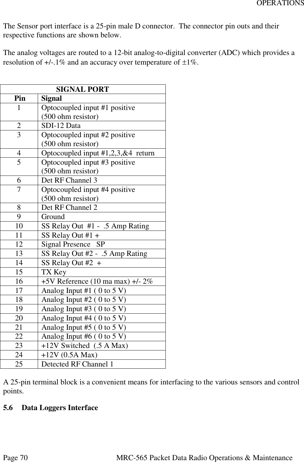
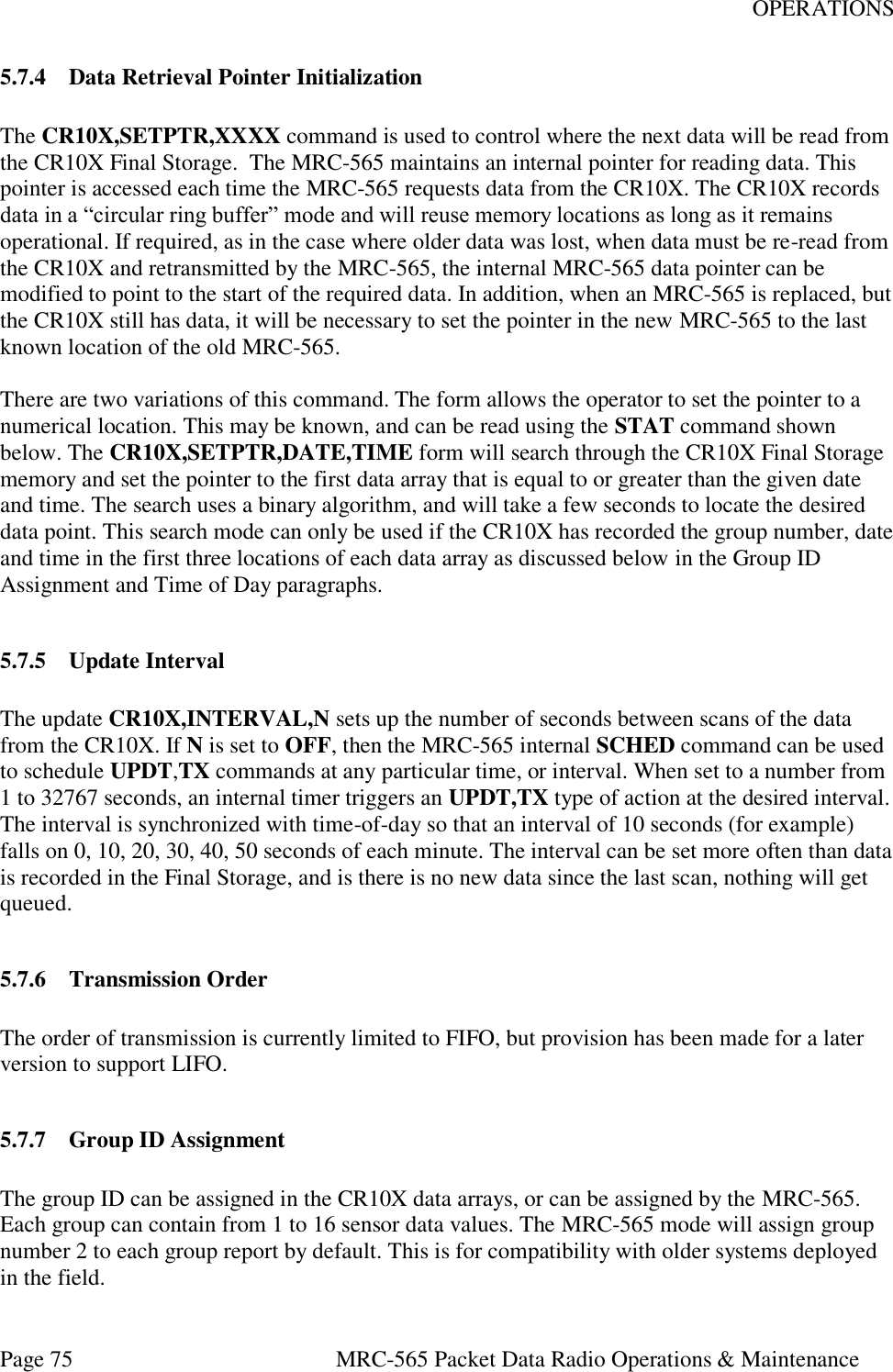
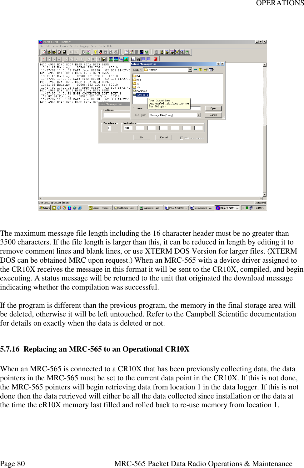
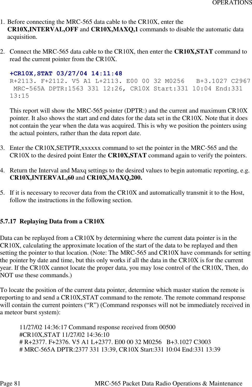
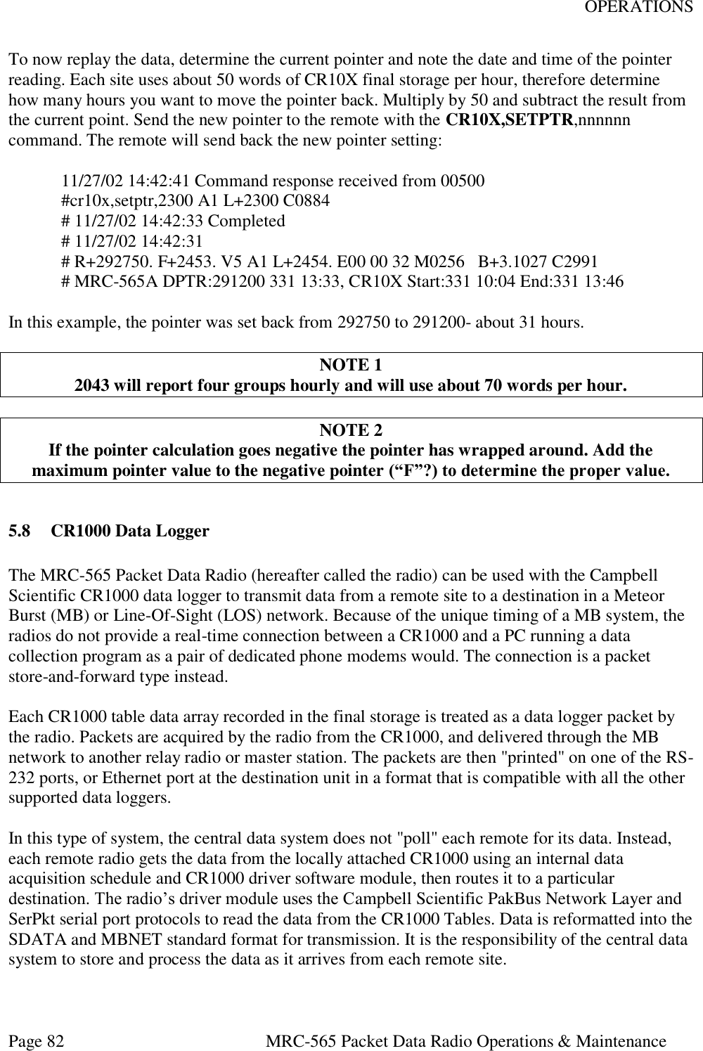
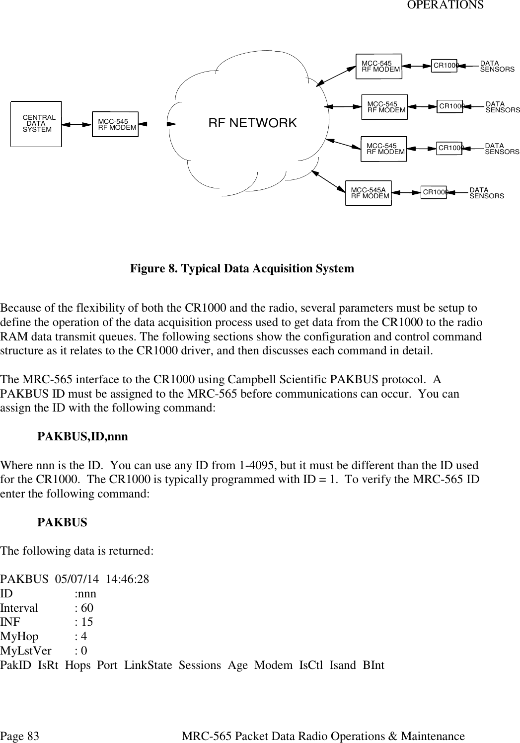
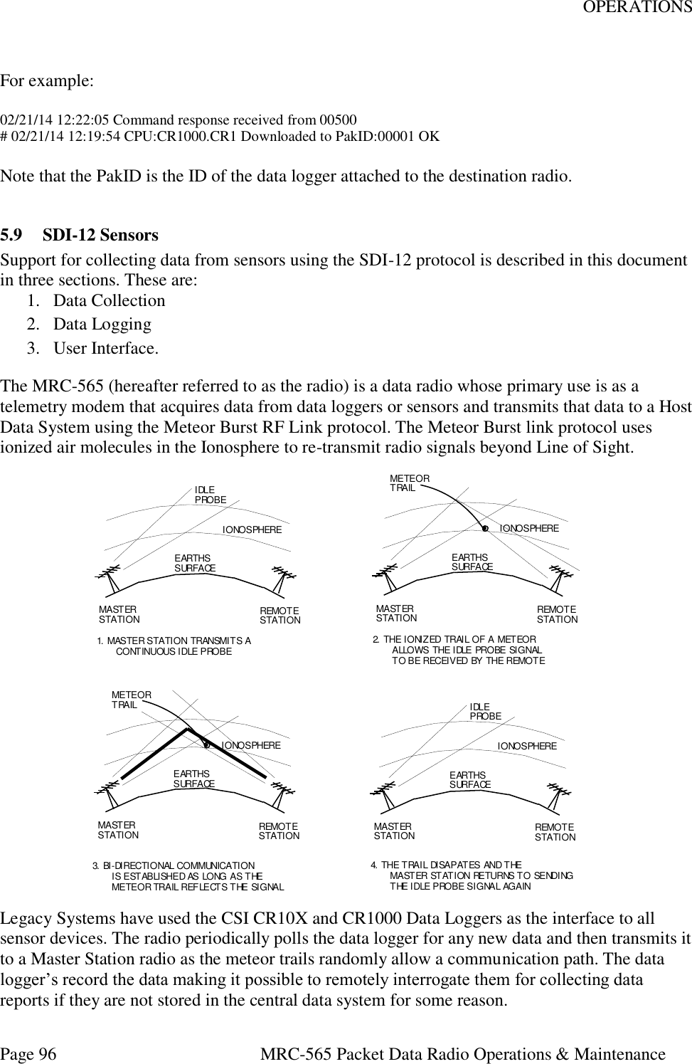
![OPERATIONS Page 71 MRC-565 Packet Data Radio Operations & Maintenance Any data logger that MRC supports and has an RS-232 interface may be connected to any one of the 3 ports on the MRC-565. Normally, the Data or AUX Port is used. You may connect to either port using a 9-pin “D” type connector: PIN FUNCTION 2 TX Data 3 RX Data 5 Ground Three commands are required to configure the Data Port for proper operation with the particular data logger being used: ASSIGN,DTA,OFF [ENTER] ASSIGN, DTA, 1, type [ENTER] The first command clears any previous assignments that still may be in effect for the DTA Port. The second command assigns a specific type of data logger and protocol to the DTA Port. The specific type of data loggers that MRC supports may be obtained from MRC or your System Administrator. The following section explains the interface of Campbell Scientific Data LoggerS to MRC-565. 5.7 CR10X Data Logger The MRC-565 RF Modem can be used with the Campbell Scientific CR10X data logger to transmit data from a remote site to a destination in a Meteor Burst (MB) or Line-Of-Sight (LOS) network. Because of the unique timing of a MB system, the MRC-565 does not provide a real-time connection between a CR10X and a PC running a data collection program as a pair of dedicated phone modems would. The connection is a packet store-and-forward type instead. The design approach used was not to add the MRC-565 to the list of modems supported by the CR10X, but to add the CR10X to the list of data loggers supported by the MRC-565. Each CR10X data-array recorded in the final storage is treated as a data logger packet by the MRC-565. Packets are acquired by the MRC-565 from the CR10X, and delivered through the MB network to another MRC-565 or master station. The packets are then “printed” on one of the RS-232 ports at the destination unit in a format that is compatible with all the other supported data loggers. In this type of system, the central data system does not “poll” each remote for its data. Instead, each remote MRC-565 gets the data from the locally attached CR10X using an internal data acquisition schedule and CR10X driver software module, then routes it to a particular destination. The MRC-565 driver module uses the CR10X telecommunications commands to read the data from the final storage. It is then the responsibility of the central data system to store and process the data as it arrives from each remote site.](https://usermanual.wiki/Maiden-Rock-Communications/MRC565-40-43/User-Guide-2352454-Page-71.png)
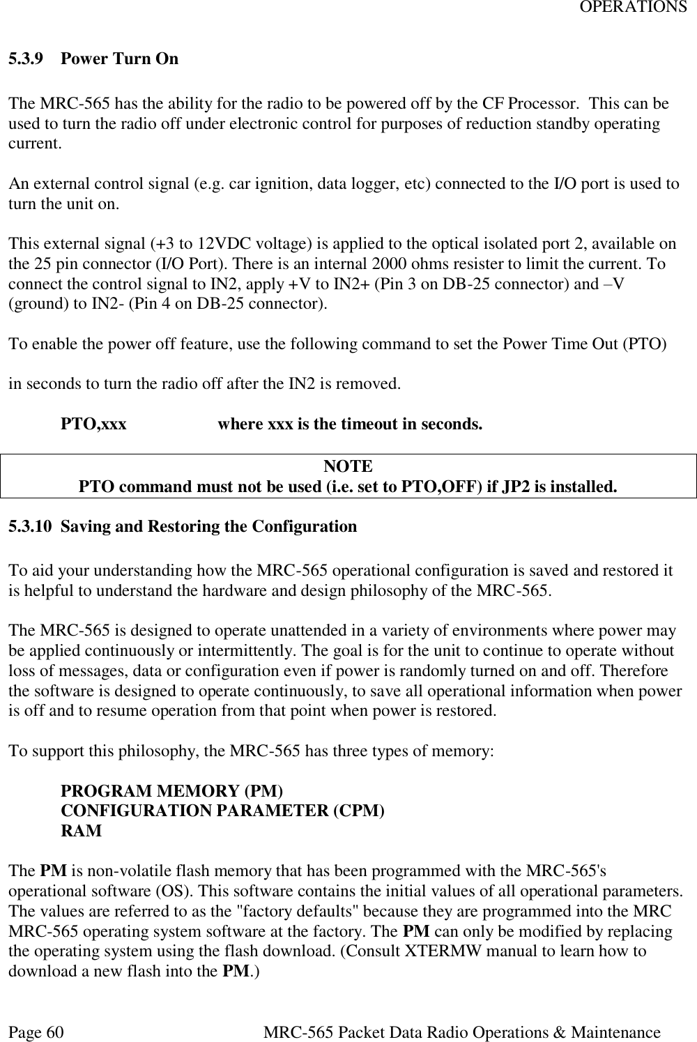
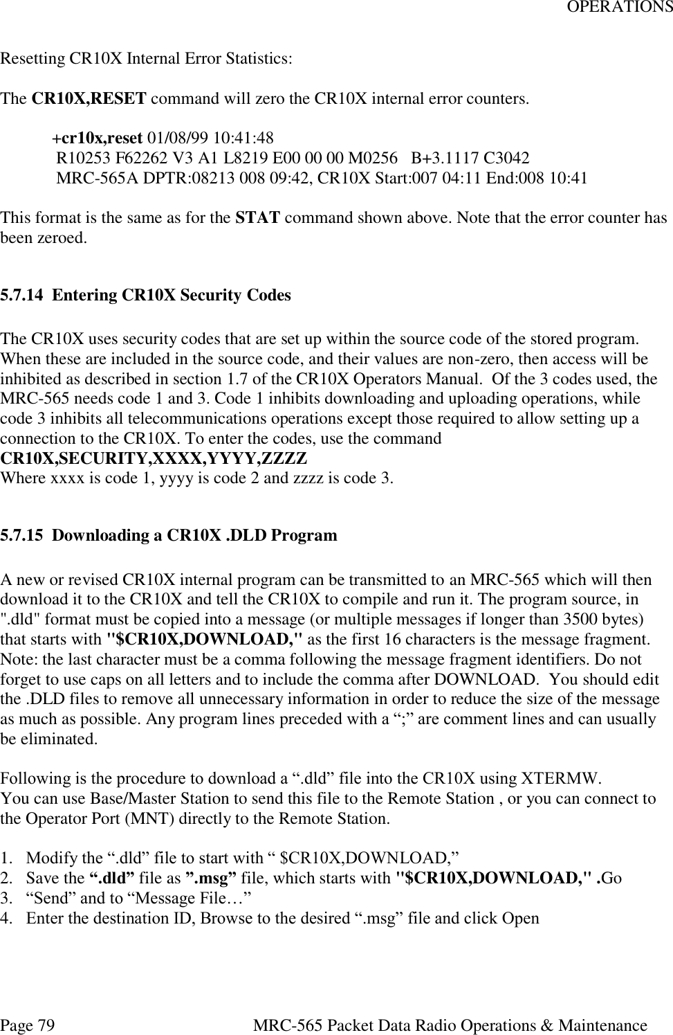
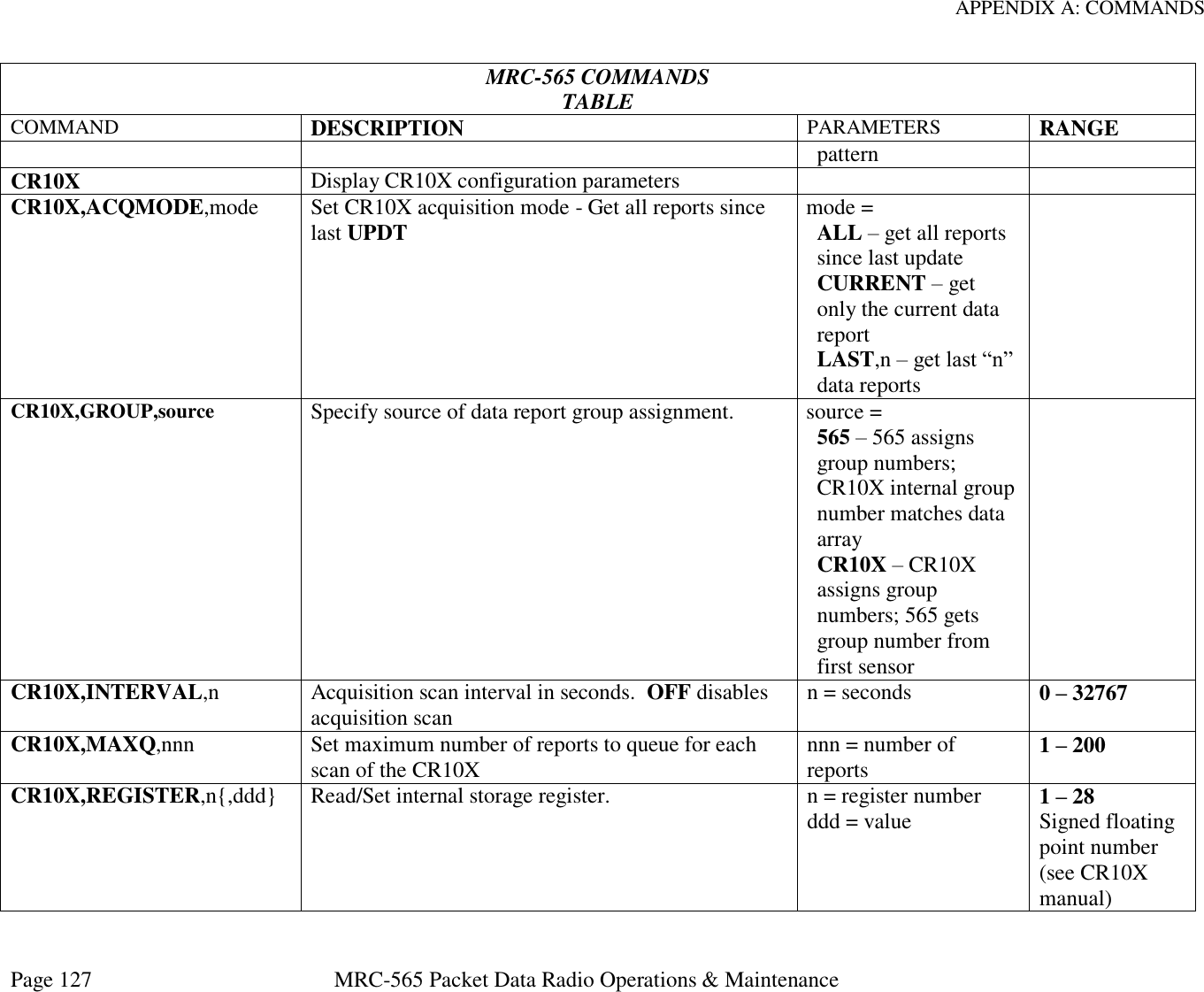
![OPERATIONS Page 78 MRC-565 Packet Data Radio Operations & Maintenance 5.7.13 Setting/Reading CR10X Internal Registers The CR10X has internal registers that are used to hold data while it is being manipulated prior to being output to final storage memory. The MRC-565 can read these registers using local or remote commands and transmit the contents back to the originator of the remote command. In addition the contents of the registers can be changed via remote command. This capability allows the CR10X internal program to access a register value as a parameter that can be changed remotely. Some uses might include controlling switches, motors, software options, final storage update rate, input scan rate, etc. To read a register use the command CR10X,REGISTER,N where "n" is the register number. The result will be displayed as follows: +cr10x,register,1 01/08/99 10:42:37 [+12.355 ] The current value in the register is shown within the square brackets. To change a register use the command CR10X,REGISTER,N,XXXX where "n" is the register number and "XXXX" is the new contents in decimal or "0xHHHH" is the new contents in hexadecimal. The following example shows the old value in square brackets followed by the new value. +cr10x,register,1,10.4 01/08/99 10:42:49 [+12.355 ] +10.400 Reading CR10X Internal Pointers and Error Statistics: The CR10X,STAT command will read and display the CR10X internal pointers and error counters. The following example shows the response format: +cr10x,stat 01/08/99 10:39:44 R10185 F62262 V3 A1 L10151 E00 02 00 M0256 B+3.1117 C2858 MRC-565A DPTR:08219 008 09:42, CR10X Start:007 04:09 End:008 10:39 The first line of the response is the “A” command response from the CR10X. It shows “R”xxxx the current data pointer, “F”xxxx the number of filled memory locations, “A”x the storage area number, “L”xxxx the last modem pointer, “E”xx xx xx error statistics, “M”xxxx memory size, and “B”xxxx internal battery voltage. The “C”xxxx is a checksum value and not otherwise useful. The second line is the MRC-565 current data pointer value, the Julian day and time (hr:mn) of the report at that location, the day and time of the oldest and newest report in the CR10X Final Storage memory. The values on this line depend on the format of the data arrays having the Julian day and time in the first two sensor locations as discussed in the “Time Tagging” paragraph above.](https://usermanual.wiki/Maiden-Rock-Communications/MRC565-40-43/User-Guide-2352454-Page-78.png)

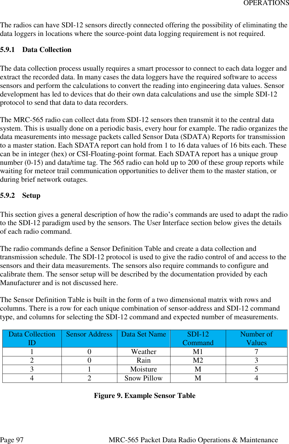
![OPERATIONS Page 98 MRC-565 Packet Data Radio Operations & Maintenance Some sensors will output several measurements with one SDI-12 command. Others can, or will, require several SDI-12 commands to collect all of the data measurements. The extended SDI-12 commands can be used to collect some particular measurements that are specific and pertain to different features or capabilities of that sensor. The transparent mode will be used to control and configure sensors. When one sensor has several sets of data that require different SDI-12 commands to access, it will be necessary to use the same sensor address in several rows of the table as in row 1-2 of the example table. The row number becomes the collection ID for data collection and reporting purposes. The columns of each row are configured parameters to define a sensor address, a data set reference name, SDI command required and number of expected measurements. The SDI, SEN, ID, ADDR, MTYPE,NVAL command creates the table rows. The EVENT, GROUP, N, SDI[R:M], SDI[R:M], SDI[R:M]… command “maps” which data values in the Sensor Table are to be combined into each SDATA group message. The number ‘N’ is the group number (1-16). Each parameter following ‘N’ is a data value ID. There can be from 1 to 16 data values. The data values can be pre-defined radio values (see radio HELP,EVENT command) or they can be SDI-12 sensor measurements. Using the pre-defined name of SDI[] in the command will specify a row [R] and measurement number [M]. For example SDI[3:2] specifies row 3 and measurement 2. In this way, any measurement can be reported in any group number and slot. There can be up to 16 groups with 16 values each for a total of 256 values per radio (or data collection site). The format of the group SDATA reports are exactly the same as those created for data logger sites. Both data logger reports and SDI sensor reports can be created for one site, but the total is limited to 16 groups and the data groups can not contain SDI measurements and Vice Versa. As an example we could define two group SDATA reports from the Example Table: EVENT,GROUP,1,SDI[1:1],SDI[1:2],SDI[1:3],SDI[1:4],SDI[1:5],SDI[1:6],SDI[1:7], SDI[2:1],SDI[2:2],SDI[2:3] EVENT,GROUP,2,SDI[3:1],SDI[3:2],SDI[3:3],SDI[3:4],SDI[3:5],SDI[4:1],SDI[4:2], SDI[4:3],SDI[4:4] After the Sensor Table and Group definitions are completed, they are saved in the configuration Flash Memory with all the other radio setup command parameters. 5.9.3 Periodic Data Collection After the Sensor Table is set up, a schedule needs to be created to tell the radio when to collect the data and when to build and transmit the SDATA reports.](https://usermanual.wiki/Maiden-Rock-Communications/MRC565-40-43/User-Guide-2352454-Page-98.png)
![OPERATIONS Page 102 MRC-565 Packet Data Radio Operations & Maintenance 5.9.6.5 EVENT, GROUP, GN, SDI[1:1], SDI[1:2], SDI[1:3]… Define a new Event Group or replace the old Event Group with this GN where: GN New Group number (1-16) SDI[x:y] Each entry specifies which Sensor Table entry (x) and which measurement number (y) (1-64) to record in that slot of the SDATA message. There is a maximum of 16 slots in each SDATA message. They will be formatted as 16-bit CSI floating point numbers. Example: EVENT,GROUP,1,SDI[1:1},SDI{1:2],SDI[1:3]<CR> 5.9.6.6 SDI, COLLECT, 1, 2, 3… This command triggers the data collection of each Sensor Table entry listed as a parameter. Up to 10 sensor table numbers can be given in each command. The command processing will scan the table and immediately collect all type ‘M’ sensor measurements if finds. It will start all type ‘C’ concurrent measurements it finds then wait for them to complete, and finally collect the data from the sensors. All the data collected is stored in the Sensor Table rows for the given sensors and can be viewed with the SDI command. 5.9.6.7 EVENT, UPDT, G The EVENT, UPDT command runs the SDATA group building function for the G group number given. One SDATA group report is created for each UPDT command. The SDATA builder extracts data from the Sensor Table. This command should be scheduled after the COLLECT command has completed gathering all the sensor data. The data measurements remain in the table and can be looked at or transmitted again without updating if that is appropriate for the particular sensor. 5.9.6.8 SCHED, I, TIME, ANY COMMAND TEXT The command scheduler can hold up to 50 entries and has several options as shown by its HELP text below. +HELP,SCHED 05/15/14 19:05:35 SCHED Show Schedule SCHED,DEL,N Notes: N is the sched item number SCHED,DEL,ALL TOD can be hh:mm:ss or mm:ss or ss SCHED,I,TOD,<cmd-string> SCHED,I,TOD,OFFSET,TOD,<cmd-string> SCHED,T,TOD,<cmd-string> SCHED,T,TOD,OFFSET,TOD,<cmd-string>](https://usermanual.wiki/Maiden-Rock-Communications/MRC565-40-43/User-Guide-2352454-Page-102.png)
![OPERATIONS Page 103 MRC-565 Packet Data Radio Operations & Maintenance To schedule data collection for our sensors and transmission of the GROUP SDATA report we could enter the following commands: SCHED,I,30:0,SDI,COLLECT,1,2 SCHED,I,30:0,OFFSET,15,EVENT,UPDT,1 The first command schedules data collection of sensor table items 1 and 2 every 30 minutes and 00 seconds. The second command schedules the event group 1 to be created and send every 30 seconds with an offset of 15 seconds to give time for the data collection to complete. 5.9.7 SDI, CMD, COMMAND TEXT Transparent Mode command. This command will output the text to the SDI-12 data line exactly as typed with the ‘!’ character appended to the end. The first character must be a sensor address and the remaining characters should be some valid basic or extended SDI-12 Command. The ‘!’ character should not be entered. Example: SDI,CMD,0V<cr> A list of the basic SDI-12 commands is given at the end of this document. Some Sensor Manufacturers have their own special commands for setup and calibration which this transparent mode is designed to support. These commands are not saved in the radio configuration flash memory so if the sensor does not retain it in a power cycle it will be lost. If this command is entered as a real-time-scheduled command it will be saved in the configuration flash memory. 5.9.8 SDI, TRACE, {OFF/ON} The SDI,TRACE command is useful for debugging the setup and operation of the radio with the sensors. The example below shows a data collection from a sensor testing device that was set up to emulate a sensor. The trace output can get to be a lot of information and should not be left on for long periods or its output can overrun the radio output memory and cause the radio to reset. Be careful using this command option. Characters enclosed in the “<>” characters are transmitted out of the radio. Characters enclosed in the “[]” characters are received by the radio. The time tag is in hundredths of seconds. Example with TRACE,ON +sdi,collect,1 20:14:44.59 <BREAK> 20:14:44.60 <MARK> 20:14:44.62 <0M!> 20:14:44.69 [00056(cr)(lf)]](https://usermanual.wiki/Maiden-Rock-Communications/MRC565-40-43/User-Guide-2352454-Page-103.png)
![OPERATIONS Page 104 MRC-565 Packet Data Radio Operations & Maintenance 20:14:49.22 [0(cr)(lf)] 20:14:49.23 <BREAK> 20:14:49.24 <MARK> 20:14:49.27 <0D0!> 20:14:49.34 [0+0.0(cr)(lf)] 20:14:49.35 <BREAK> 20:14:49.36 <MARK> 20:14:49.40 <0D1!> 20:14:49.46 [0+1.0(cr)(lf)] 20:14:49.48 <BREAK> 20:14:49.49 <MARK> 20:14:49.52 <0D2!> 20:14:49.59 [0+2.0(cr)(lf)] 20:14:49.60 <BREAK> 20:14:49.61 <MARK> 20:14:49.64 <0D3!> 20:14:49.71 [0+3.0(cr)(lf)] 20:14:49.72 <BREAK> 20:14:49.73 <MARK> 20:14:49.77 <0D4!> 20:14:49.83 [0+4.0(cr)(lf)] 20:14:49.85 <BREAK> 20:14:49.86 <MARK> 20:14:49.89 <0D5!> 20:14:49.96 [0+5.0(cr)(lf)] 5.9.9 SDI-12 Command/Response List Name Command Response Break Continuous spacing for 12 ms None Acknowledge Active a! a<CR><LF> Send Identification aI! allccccccccmmmmmmvvvxxx...xx<CR><LF> Change Address aAb! b<CR><LF> (support for this command is required only if the sensor supports software changeable addresses) Address Query ?! a<CR><LF> Start Measurement* aM! atttn<CR><LF> Start Measurement + CRC* aMC! atttn<CR><LF> Send Data aD0! … aD9! a<values><CR><LF> or a<values><CRC><CR><LF> Additional Measurements* aM1! … aM9! atttn<CR><LF> Additional Measurements + CRC* aMC1! ... aMC9! atttn<CR><LF> Start Verification* aV! atttn<CR><LF> Start Concurrent Measurement aC! atttnn<CR><LF> Start Concurrent Measurement + CRC aCC! atttnn<CR><LF> Additional Concurrent Measurements aC1! … aC9! atttnn<CR><LF> Additional Concurrent + CRC aCC1! ... aCC9! atttnn<CR><LF>](https://usermanual.wiki/Maiden-Rock-Communications/MRC565-40-43/User-Guide-2352454-Page-104.png)
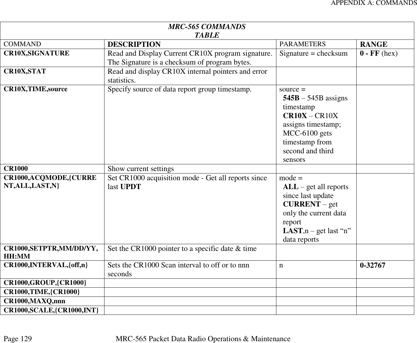
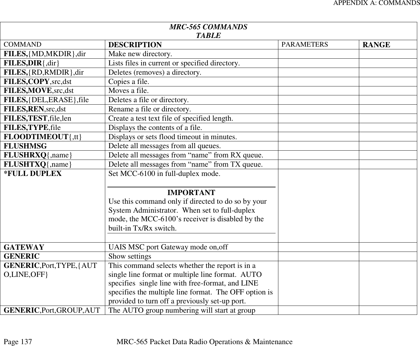
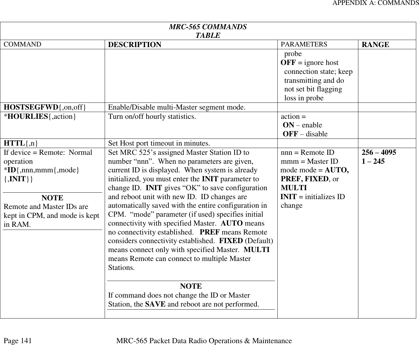
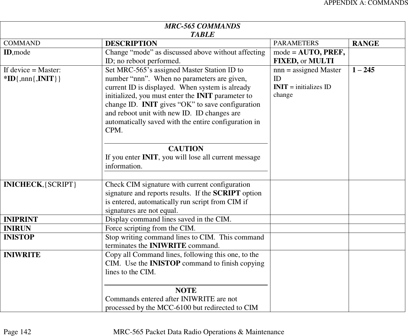
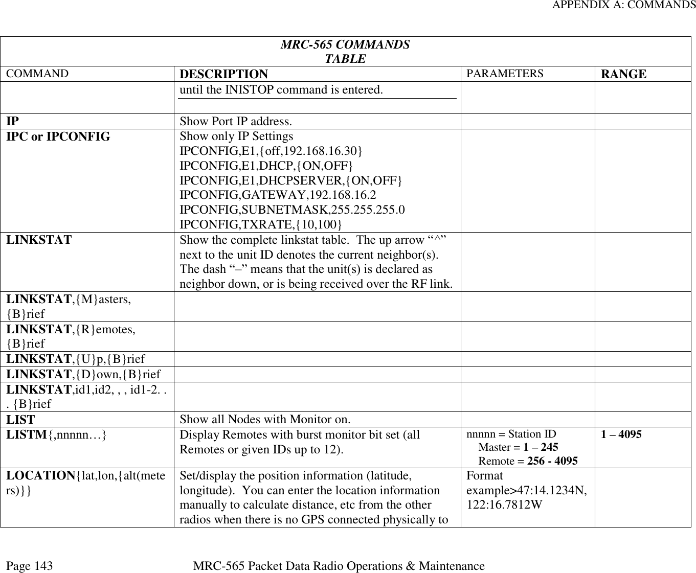
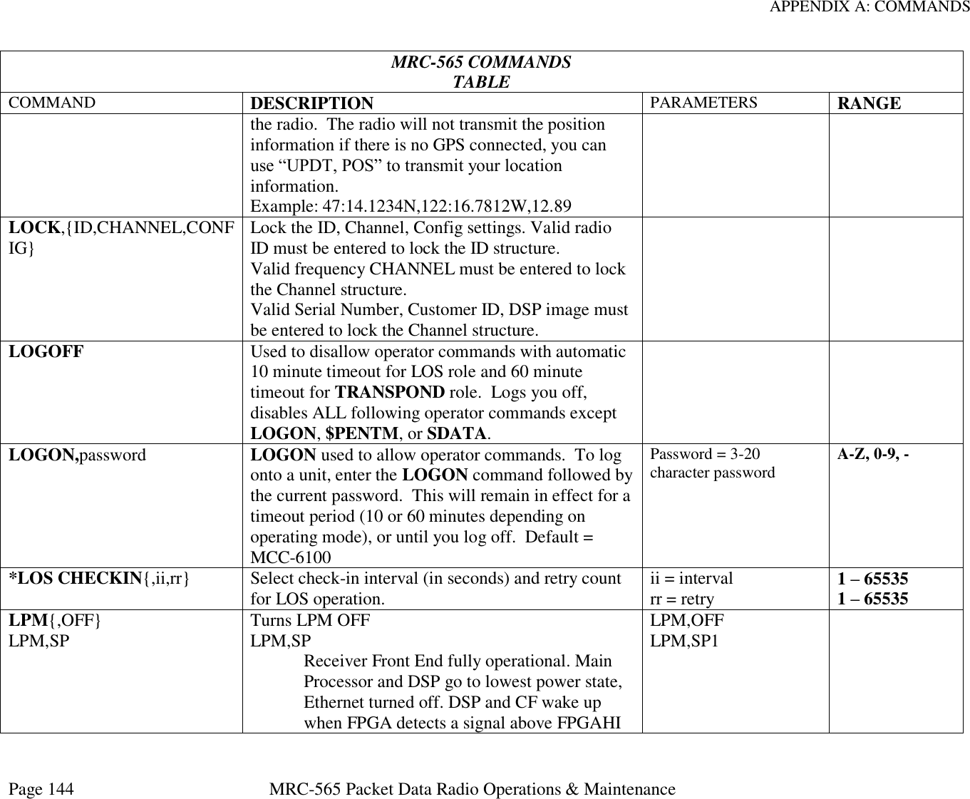
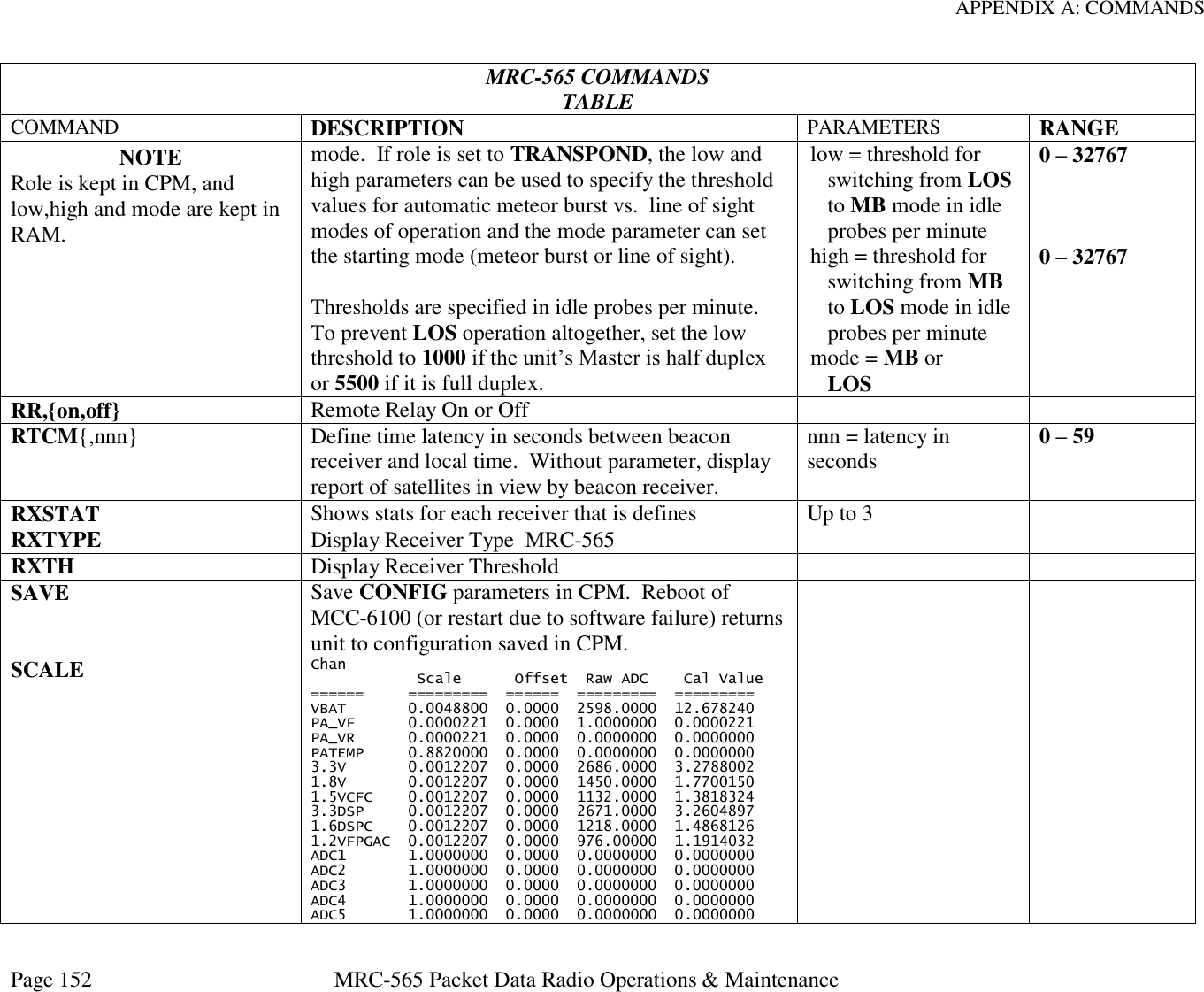
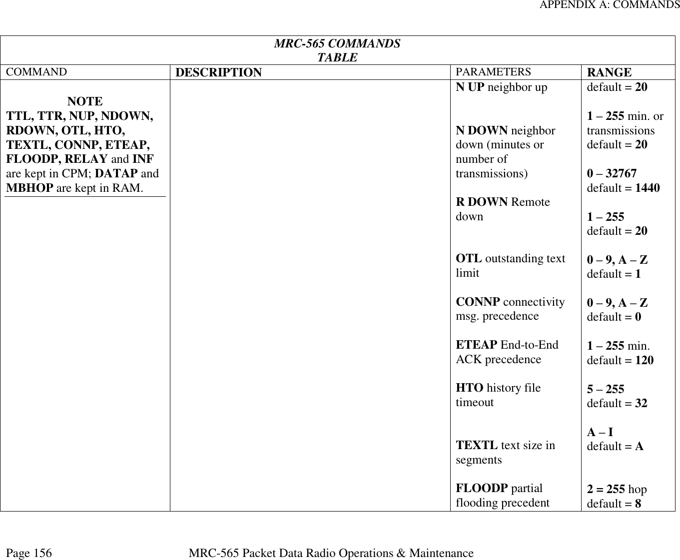
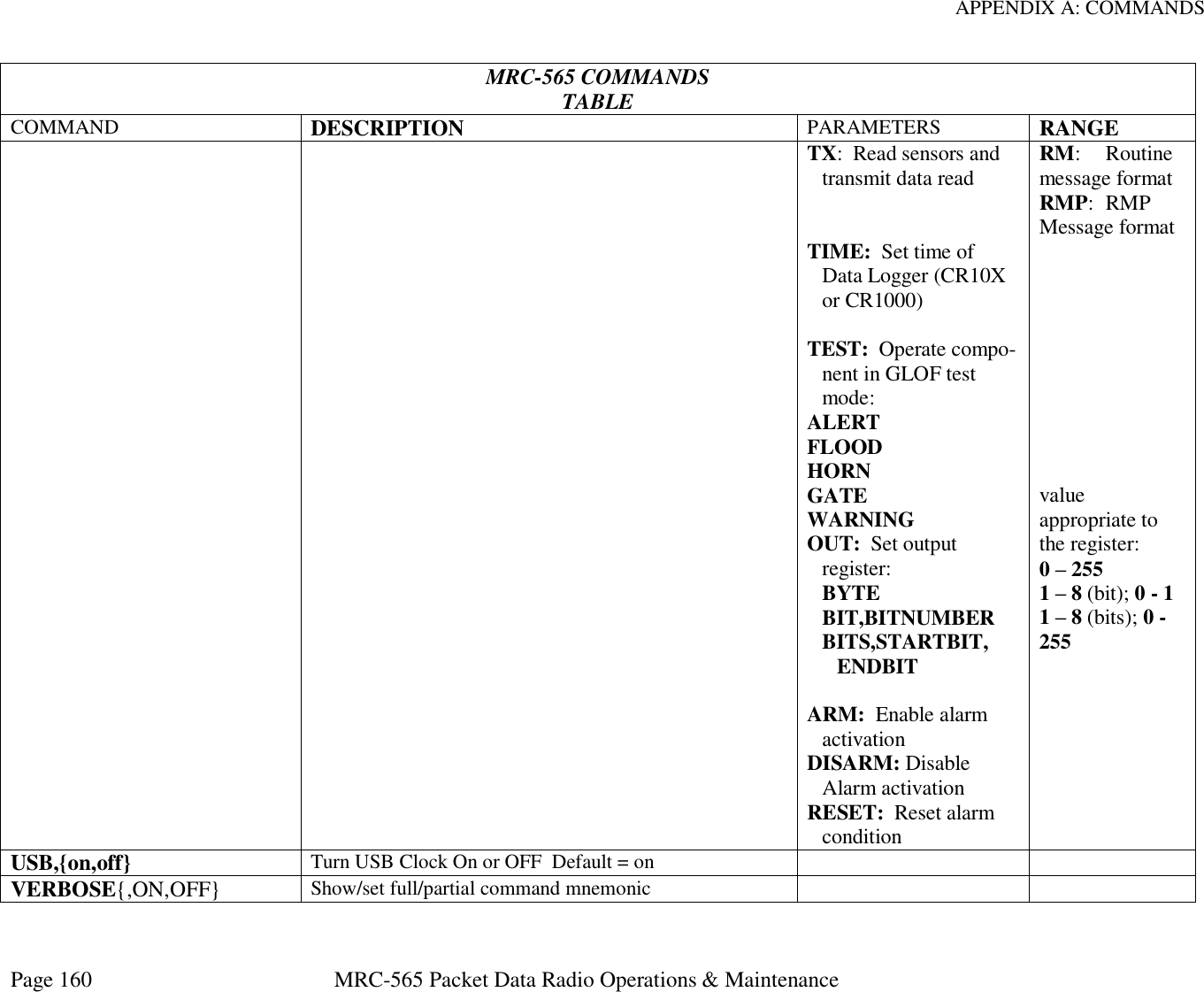
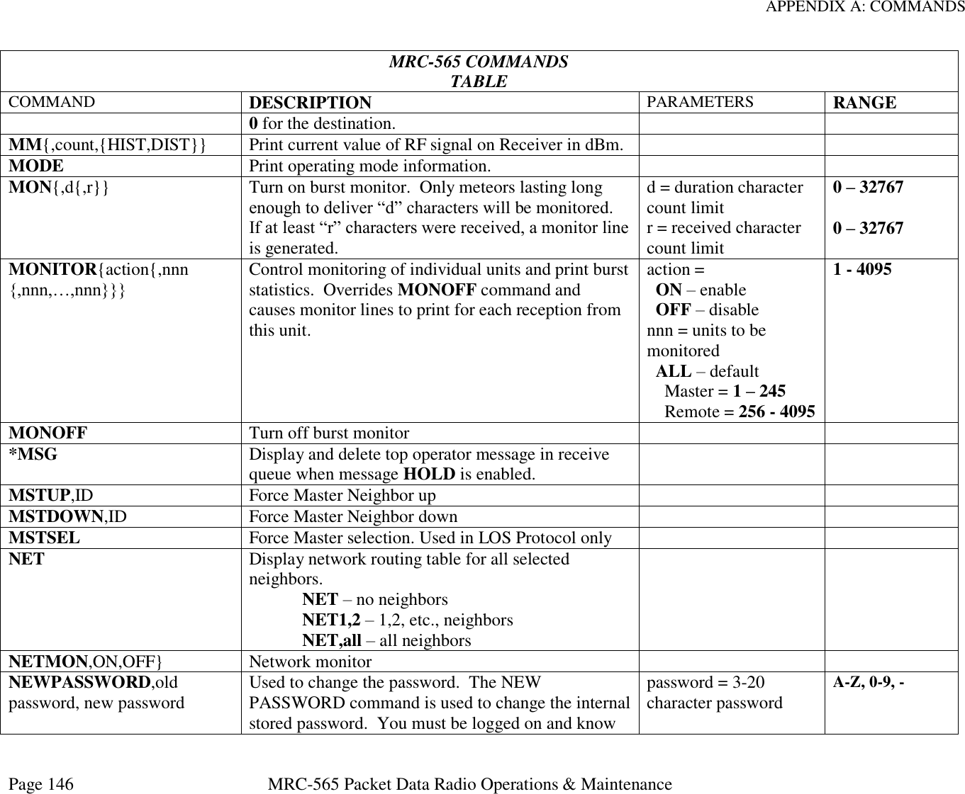
![APPENDIX A: COMMANDS Page 145 MRC-565 Packet Data Radio Operations & Maintenance MRC-565 COMMANDS TABLE COMMAND DESCRIPTION PARAMETERS RANGE threshold. Timer and Alarm can also turn everything on. Estimated Receive Current is 80ma. An internal Timer will wake up main processor for 1 sec every 10 seconds to allow a keypad entry to wake up device. Tapping a key continuously for up to 10 seconds will wake up device for 20 seconds after last keypad entry. LPM,ALARM Same as SP except Receiver front (DSP,ADC,RX CLOCK) turns off if nothing in TXQ. CPLD Timer or Alarm turns everything back on. Estimated Receive Current is 60ma. When TXQ has data, same current as in LPM,SP LPM,PWR Same as SP2 except Power to entire radio is turned off. Alarm clock or Ignition wire set to (2 to 12V). Estimated Current is 2 ma. This mode is the same as that in 545B. LPM,SP2 LPM,PWR MAINTMON,id Define Maintenance monitor node ID. MEM Show usage of dynamic pool memory. MESSAGE {,p{,dest1…destn}} Enter a message with text editor. Message priority and destination are optional parameters. After entering message, press [ESC] to queue for transmission. If you do not enter a destination ID, the MCC-6100 automatically sends your message to its default destination (set with the DESTINATION command). If you want to use source rounting, enter p = priority dest1...destn = destination(s) name = node name nnnn = Station ID Master = 1 – 245 Remote = 256 – 4095 A – Z, 0 – 9 A – Z, 0 – 9 1 – 4095](https://usermanual.wiki/Maiden-Rock-Communications/MRC565-40-43/User-Guide-2352454-Page-145.png)
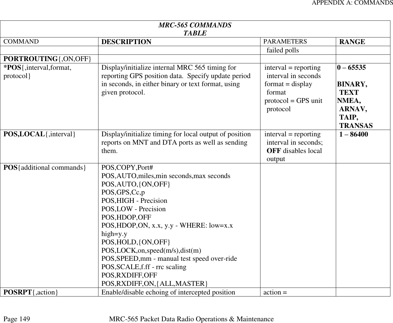
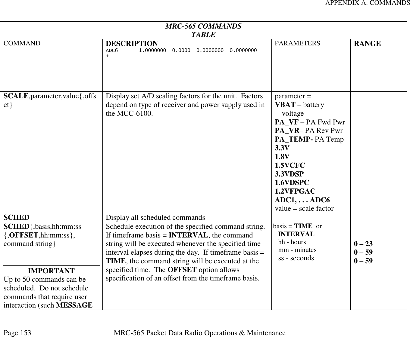
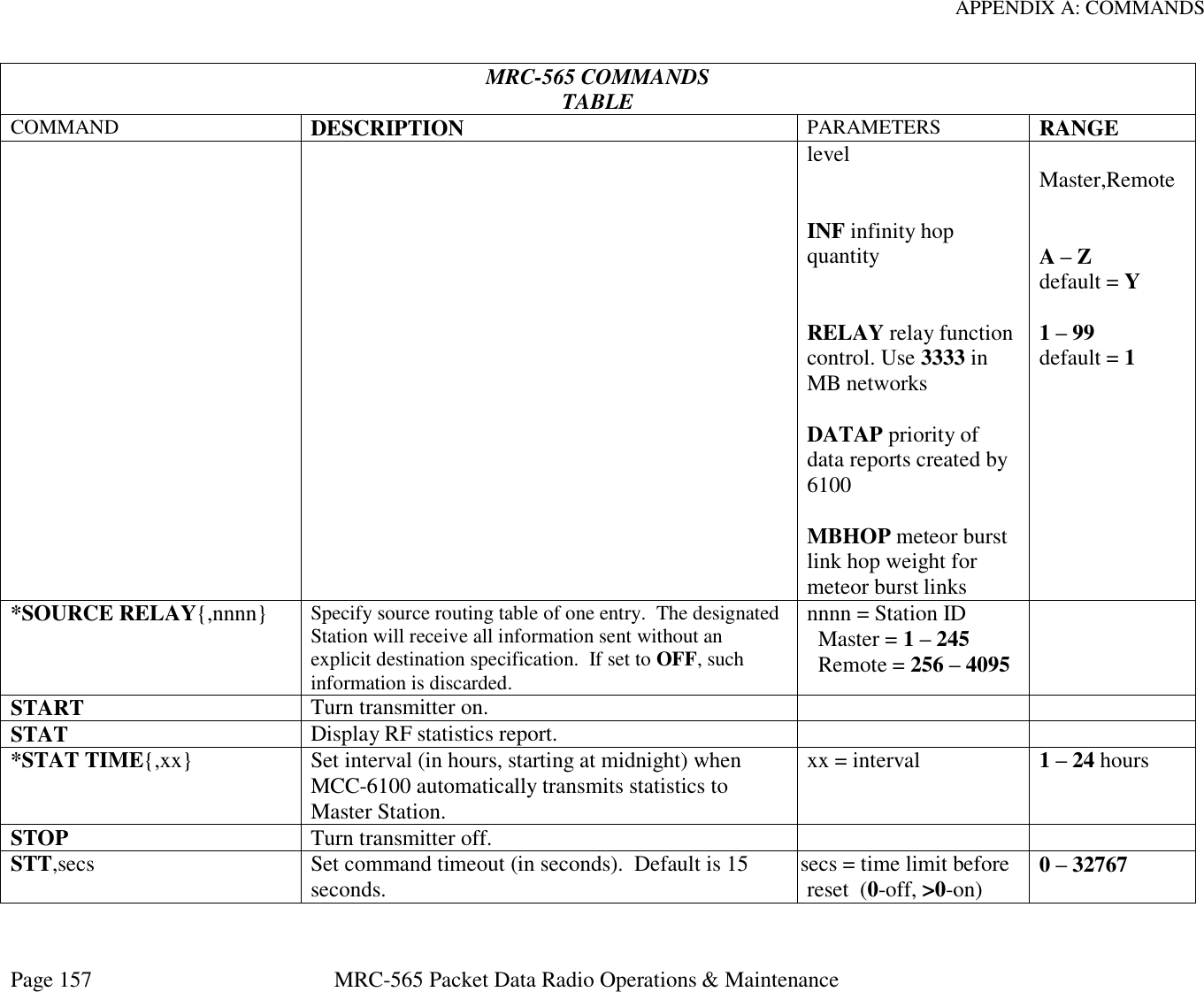
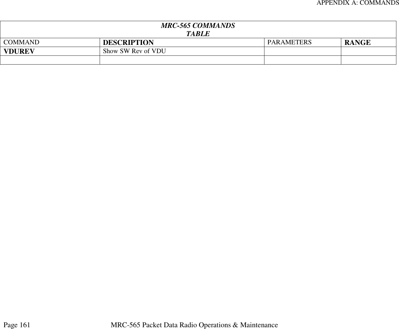
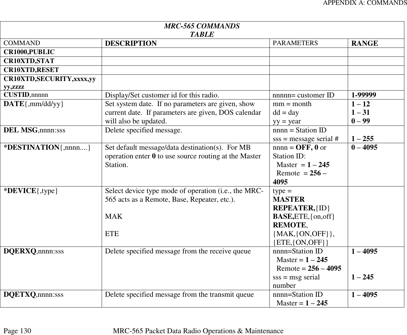
![APPENDIX A: COMMANDS Page 151 MRC-565 Packet Data Radio Operations & Maintenance MRC-565 COMMANDS TABLE COMMAND DESCRIPTION PARAMETERS RANGE ,p,dest1{,…destn} Remote. After entering command, press [ESC] to send the command. dest1…destn destination(s) name = node name nnnn = Station ID Master = 1 – 245 Remote = 256 – 4095 A – Z, 0 – 9 1 – 4095 REG Show Registration data REG,TX Transmit REG report to Default Destination REMDOWN,ID Force Remote Neighbor down REMOTES{,n} Maximum number of remotes n= # of remotes 1-4095 REMUP,ID Force Remote Neighbor up REMOTE STAT{,nnnnn…} Display transmit/receive statistics for all Remote Stations or for given IDs (up to 12). nnnn = Station ID Master = 1 – 245 Remote = 256 – 4095 REMOTE TYPE{,aaaaa} Display/set communication characteristics of the unit. Determines how certain statistics are reported and how remote commands/messages are framed. aaaaa = COMM DATA PACKET RESET Resets the DSP and FPGA Processors. Does not affect CF REV Display part and revision numbers of the: Main Processor CF DSP Processor FPGA Processor. CPLD Gate Array *ROLE{,role{,low,high} {,mode}} Define role played in network, either SILENT (never transmits), TRANSPOND (responds to probes), PROBE (actively probes), or LOS (line of sight) role = SILENT, LOS, TRANSPOND or PROBE](https://usermanual.wiki/Maiden-Rock-Communications/MRC565-40-43/User-Guide-2352454-Page-151.png)