Majestic Appliances 39Ldvr Users Manual 1 7317 LDVR
43LDVR to the manual 752a6c49-ae11-4e5a-8417-ef389ed270b0
2015-02-09
: Majestic-Appliances Majestic-Appliances-39Ldvr-Users-Manual-553110 majestic-appliances-39ldvr-users-manual-553110 majestic-appliances pdf
Open the PDF directly: View PDF ![]() .
.
Page Count: 40
Installation Instructions and
Homeownerʼs Manual
10007317 11/05 Rev. 4
INSTALLER: DO NOT DISCARD THIS MANUAL - LEAVE FOR HOMEOWNER
Builder Rear Vent
Direct Vent
Models: 33LDVR, 36LDVR,
39LDVR, 43LDVR
DO NOT STORE OR USE
GASOLINE OR OTHER
FLAMMABLE VAPORS AND
LIQUIDS IN THE VICINITY OF
THIS OR ANY OTHER
APPLIANCE.
WHAT TO DO IF YOU SMELL GAS:
• Do not try to light any appliance.
• Do not touch any electric switch;
do not use any phone in your
building.
• Immediately call your gas
supplier from your neighborʼs
phone. Follow the gas suppliers
instructions.
• If you cannot reach your gas
supplier call the fire department.
WARNING!
IF THE INFORMATION IN THIS
MANUAL IS NOT FOLLOWED
EXACTLY, A FIRE OR EXPLO-
SION MAY RESULT CAUSING
PROPERTY DAMAGE, PER-
SONAL INJURY OR LOSS OF
LIFE.
PLEASE READ THIS MANUAL
BEFORE INSTALLING AND
USING APPLIANCE
INSTALLER/CONSUMER
SAFETY INFORMATION
FOR YOUR SAFETY
Installation and service must
be performed by a qualified
installer, service agency or
the gas supplier.
410 Admiral Blvd. • Mississauga, Ontario, Canada L5T 2N6 • 905-670-7777
www.majesticproducts.com • www.vermontcastings.com
CFM Specialty Home Products
™
7317
LDVR COVER
1/05

2
LDVR Series Direct Vent Gas Fireplace
10007317
PLEASE READ THE INSTALLATION & OPERATING INSTRUCTIONS
BEFORE USING APPLIANCE.
Thank you and congratulations on your purchase of a CFM Specialty Home Products fireplace.
IMPORTANT: Read all instructions and warnings carefully before starting installation.
Failure to follow these instructions fully may result in a possible fire hazard and will void the warranty.
Table of Contents
Installation & Operating Instructions
Important Curing/Burning Instructions .................................................................................3
Locating Your Fireplace ....................................................................................................... 3
Fireplace Dimensions ..........................................................................................................4
Clearance to Combustibles .................................................................................................5
Mantels ...............................................................................................................................5
Hearth ...............................................................................................................................5
Framing and Finishing .........................................................................................................6
Final Finishing .....................................................................................................................6
Gas Specifications ...............................................................................................................6
Gas Inlet and Manifold Pressures .......................................................................................6
High Elevations ...................................................................................................................6
Gas Line Installation ............................................................................................................7
Remote ON/OFF Switch ......................................................................................................7
Alternate Switch Location ....................................................................................................7
EB-1 Electrical Box ..............................................................................................................8
Electronic Gas Control Valve ............................................................................................... 8
General Venting Information
General Venting ...................................................................................................................9
General Venting Information-Termination Location ........................................................... 10
General Information Assembling Vent Pipes ..................................................................... 11
How to Use the Vent Graph ............................................................................................... 12
Rear Wall Venting Applications & Installation ....................................................................12
Vertical Sidewall Applications & Installation ......................................................................14
Below Grade Installation ...................................................................................................17
Vertical Through-the-Roof Applications & Installation .......................................................18
Venting Components .........................................................................................................21
Operating Instructions
Glass Information ..............................................................................................................22
Louvre Removal ................................................................................................................22
Window Frame Assembly Removal ................................................................................... 22
Glass Cleaning ..................................................................................................................22
Installation of Logs, Lava Rock & Ember Material .............................................................23
Flame & Temperature Adjustment ..................................................................................... 25
Flame Characteristics ........................................................................................................25
Lighting and Operating Instructions ...................................................................................26
Troubleshooting .................................................................................................................28
Fuel Conversion Instructions .............................................................................................30
Maintenance
Cleaning the Standing Pilot Control System .....................................................................31
Replacement Parts .....................................................................................................................32
Optional Accessories
Fan Kits .............................................................................................................................35
Ceramic Refractory Lining .................................................................................................36
Remote Controls ...............................................................................................................36
Trim Kits ............................................................................................................................37
Screen Door Kits ...............................................................................................................37
Filigree Louvre Kits ............................................................................................................37
Warranty .......................................................................................................................................39
Energuide .....................................................................................................................................40
3
LDVR Series Direct Vent Gas Fireplace
10007317
This gas appliance should be installed by a qualified
installer in accordance with local building codes and with
current CSA-B149.1 Installation codes for Gas Burning
Appliances and Equipment. For USA Installations follow
local codes and/or the current National Fuel Gas Code.
ANSI Z223.1/NFPA 54.
In the Commonwealth of Massachusetts, all gas fitting
and installation of this heater shall only be done by a
licensed gas fitter or licensed plumber.
FOR SAFE INSTALLATION AND OPERATION PLEASE
NOTE THE FOLLOWING:
1. This fireplace gives off high temperatures and should be
located out of high traffic areas and away from furniture
and draperies.
2. Children and adults should be alerted to the hazards of
high surface temperatures of this fireplace and should stay
away to avoid burns or ignition of clothing.
3. CAUTION: Due to high glass surface temperature chil-
dren should be carefully supervised when in the same
room as fireplace.
4. Under no circumstances should this fireplace be modified.
Parts removed for servicing should be replaced prior to
operating this fireplace again.
5. Installation and any repairs to this fireplace must be
performed by a qualified installer, service agency or gas
supplier. A professional service person should be contacted
to inspect this fireplace annually. Make it a practice to have
all of your gas fireplaces checked annually. More frequent
cleaning may be required due to excess lint and dust from
carpeting, bedding material, etc.
6. Control compartments, burners and air passages in this
fireplace should be kept clean and free of dust and lint.
Make sure the gas valve and pilot light are turned off before
you attempt to clean this fireplace.
7. The venting system (chimney) of this fireplace should be
checked at least once a year and if needed your venting
system should be cleaned.
8. Keep the area around your fireplace clear of combustible
materials, gasoline and other flammable vapor and liquids.
This fireplace should not be used as a drying rack for cloth-
ing, nor should Christmas stockings or decorations be hung
on or around the fireplace.
9. Under no circumstances should any solid fuels (wood, coal,
paper or cardboard etc.) be used in this fireplace.
10. The flow of combustion and ventilation air must not be
obstructed in any way.
11. When fireplace is installed directly on carpeting, vinyl tile
or any combustible material other than wood, the fireplace
must be installed on a metal or wood panel extending the
full width and depth of the fireplace.
12. This fireplace requires adequate ventilation and combustion
air to operate properly.
13. This fireplace must not be connected to a chimney flue
serving a separate solid fuel burning fireplace.
14. When the fireplace is not in use it is recommended that the
gas valve be left in the OFF position.
15. These units have been approved for bedroom use.
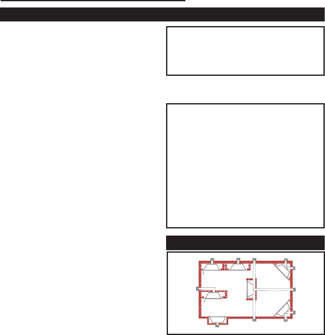
A) Flat on wall B) Cross corner C) **Island
D) *Room divider E) *Flat on wall corner F) Chase installation
Y) 6” minimum
NOTE: (fig. 1)
** Island (C) and Room Divider (D) installation is possible as
long as the horizontal portion of the vent system (X) does not
exceed 20ʼ (610cm). See details in Venting Section.
* When you install your fireplace in(D) Room divider or (E) Flat
on wall corner positions (Y), a minimum of 6” (153mm) clear-
ance must be maintained from the perpendicular wall and the
front side edge of the fireplace.
Refer to (Y) in Figure 1.
IMPORTANT:
PLEASE REVIEW THE FOLLOWING CAREFULLY
Remove any plastic from trim parts before turning the fireplace
ON.
It is normal for fireplaces fabricated of steel to give off some
expansion and/or contraction noises during the start up or cool
down cycle. Similar noises are found with your furnace heat
exchanger or car engine.
It is not unusual for your gas fireplace to give off some odor
the first time it is burned. This is due to the curing of the paint
and any undetected oil from the manufacturing process.
Please ensure that your room is well ventilated - open
all windows.
It is recommended that you burn your fireplace for at least
ten (10) hours the first time you use it. If the optional fan kit
has been installed, place the fan switch in the “OFF” position
during this time.
Locating Your Fireplace
Y
EAB
C
D
F
YB
X
LU584-R
Locating unit
2/23/01 sta
X
Installation & Operating Instructions
LU584-R
Fig. 1 Locate gas fireplace.
Proposition 65 Warning: Fuels used in gas, wood-
burning or oil fired appliances, and the products of
combustion of such fuels, contain chemicals known to
the State of California to cause cancer, birth defects
and other reproductive harm.
California Health & Safety Code Sec. 25249.6
WARNING: Check with your electronics manufacturer
before installing a television or other electronic de-
vice above this fireplace.
4
LDVR Series Direct Vent Gas Fireplace
10007317
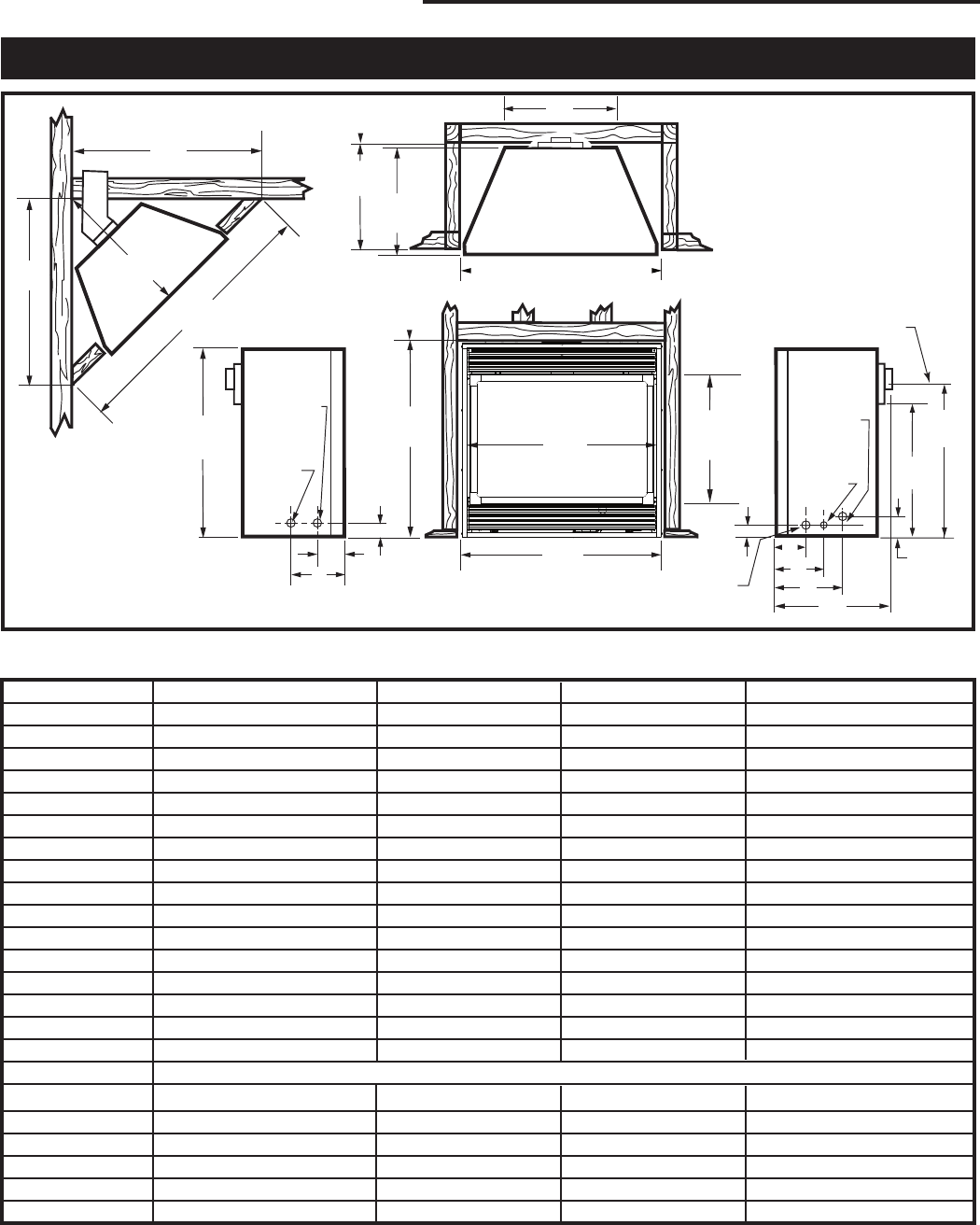
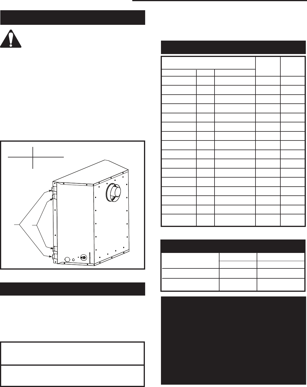
Fireplace Dimensions
F
V - Rough Opening Width
Rough
Opening
Height
Rough
Opening
Depth
S
S
U
T
R
E
I
H
J
D
A
Q
B
K
L
G
M
O
Gas Line
Access
Gas Line
Access
Low
Voltage
Electrical
Access
Electrical
Access
C
Centerline of
7" Collar
M
N
P
Low
Voltage
Access
Fig. 2 Fireplace specifications and framing dimensions.
Ref. 33LDVR 36LDVR 39LDVR 43LDVR
A 33” (838 mm) 36” (914 mm) 39” (991 mm) 43” (1092 mm)
B 28⁷⁄₈” (733 mm) 34¹⁄₄” (870 mm) 34¹⁄₄” (870 mm) 37” (940 mm)
C 31¹⁄₄” (794 mm) 34¹⁄₄” (870 mm) 37¹⁄₄” (946 mm) 41¹⁄₄” (1048 mm)
D 18³⁄₈” (466 mm) 23” (584 mm) 23” (584 mm) 25³⁄₄” (654 mm)
E 24⁷⁄₈” (632 mm) 24” (610 mm) 27” (686 mm) 31” (788 mm)
F 11¹⁄₂” (292 mm) 16” (406 mm) 16” (406 mm) 16” (406 mm)
G 14¹⁄₄” (362 mm) 18³⁄₄” (476 mm) 18³⁄₄” (476 mm) 18³⁄₄” (476 mm)
H 19³⁄₄” (501 mm) 24¹⁄₄” (616 mm) 24¹⁄₄” (616 mm) 27” (686 mm)
I 23¹⁄₄” (590 mm) 27³⁄₄” (705 mm) 27³⁄₄” (705 mm) 30¹⁄₂” (775 mm)
J 4³⁄₄” (121 mm) 5⁵⁄₈” (143 mm) 5⁵⁄₈” (143 mm) 5⁵⁄₈” (143 mm)
K 6⁵⁄₁₆” (160 mm) 8” (203 mm) 8” (203 mm) 8” (203 mm)
L 8⁷⁄₈” (225 mm) 11⁷⁄₈” (302 mm) 11⁷⁄₈” (302 mm) 11⁷⁄₈” (302 mm)
M 2” (51 mm) 2” (51 mm) 2” (51 mm) 2” (51 mm)
N 3³⁄₈” (86 mm) 3¹⁄₄” (83 mm) 3¹⁄₄” (83 mm) 3¹⁄₄” (83 mm)
O 4³⁄₄” (121 mm) 6³⁄₄” (172 mm) 6³⁄₄” (172 mm) 6³⁄₄” (172 mm)
P 6⁵⁄₁₆” (160 mm) 9¹⁄₄” (235 mm) 9¹⁄₄” (235 mm) 9¹⁄₄” (235 mm)
Framing Dimensions
Q 29⁵⁄₈” (753 mm) 35” (889 mm) 35” (889 mm) 37³⁄₄” (959 mm)
R 12” (305 mm) 16¹⁄₂” (419 mm) 16¹⁄₂” (419 mm) 16¹⁄₂” (419 mm)
S 36” (914 mm) 41⁵⁄₈” (1057 mm) 44” (1118 mm) 44¹⁄₈” (1121 mm)
T 51” 1295 mm) 58⁷⁄₈” (1495 mm) 62¹⁄₄” (1581 mm) 62³⁄₈” (1584 mm)
U 25¹⁄₂” (648 mm) 29⁷⁄₈“ (748 mm) 31¹⁄₈” (790 mm) 31¹⁄₄” (794 mm)
V 33¹⁄₂” (851 mm) 36¹⁄₂” (927 mm) 39¹⁄₂” (1003 mm) 43¹⁄₂” (1105 mm)
5
LDVR Series Direct Vent Gas Fireplace
10007317
Top of Unit to Ceiling ............................. 36” (914mm)
Appliance
Top ....................................................... 0” (0 mm)
Bottom .................................................. 0” (0 mm)
Side ...................................................... 0” (0 mm)
Back ..................................................... 0” (0 mm)
Venting
Concentric sections of DV Vent
Top, bottom & sides ........................... 1” (25 mm)
Rear Vent Applications:
Top ..................................................... 2” (50 mm)
Sides and Bottom ............................... 1” (25 mm)
A hearth is not mandatory but is recommended for
aesthetic purposes. We recommend a noncombustible
hearth which projects out 12” (305mm) or more from
the front of the fireplace.
Cold climate installation recommendation:
When installing this unit against a
non-insulated exterior wall or chase,
it is mandatory that the outer walls
be insulated to conform to applicable
insulation codes.
Hearth
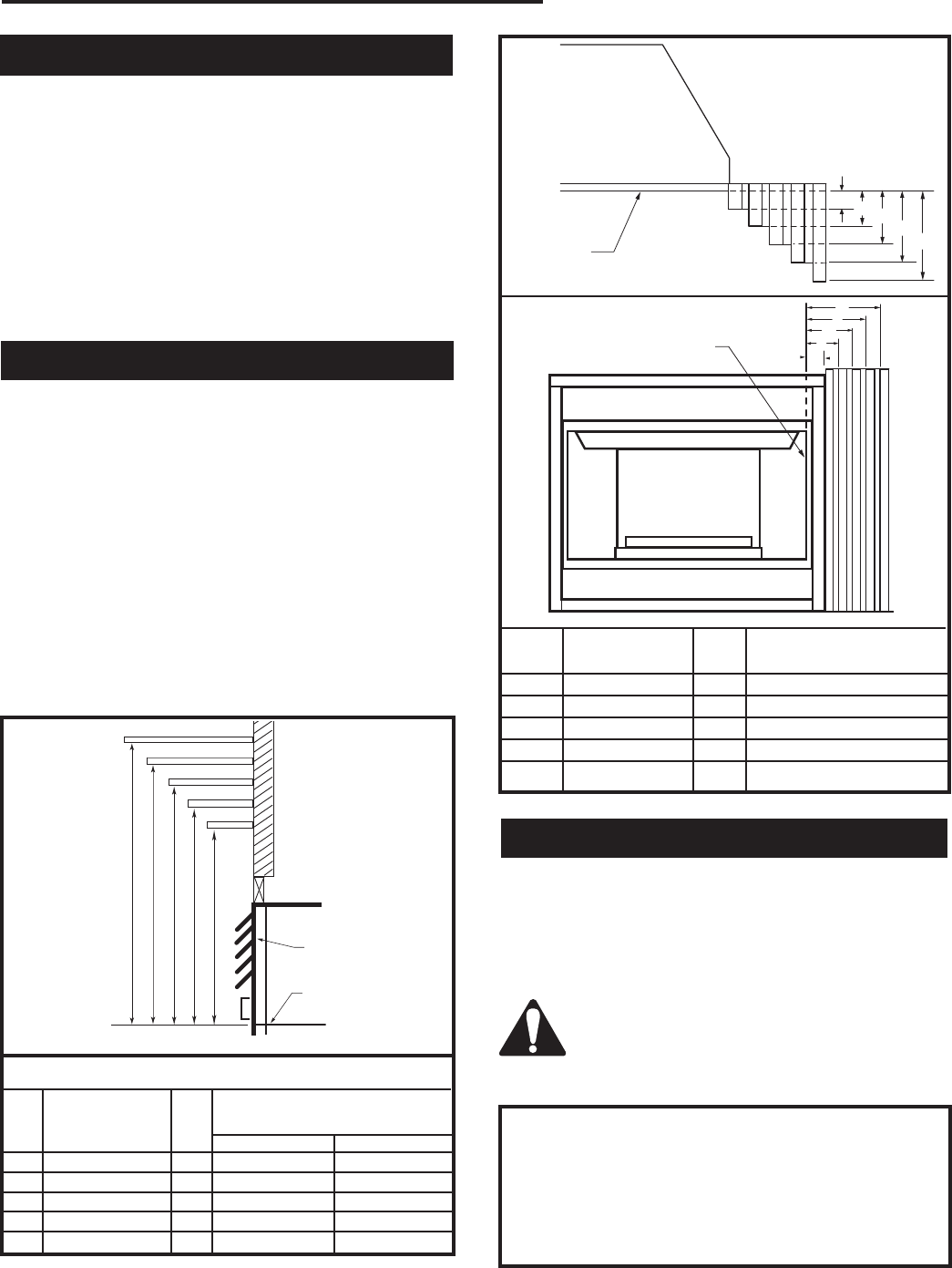
Mantels
The height that a combustible mantel is fitted above the
fireplace is dependent on the depth of the mantel. This
also applies to the distance between the mantel leg (if
fitted) and the fireplace.
For the correct mounting height and widths refer to
Figs. 3a and 3b, and the following Mantel Charts.
The fitting of a bay window trim kit does not effect
the distances and reference points referred to in the
diagram and chart.
Noncombustible mantels and legs may be installed at
any height and width around the appliance.
When using paint or lacquer to finish the mantel, such
paint or lacquer must be heat resistant to prevent
discoloration.
Clearance to Combustibles
CFM170
J
F
G
H
I
Mantel
Leg
CFM164a
Mantel Leg Chart
06/22/01 sta
Black
Surround
Face
CFM170
DV Builder Front
View
O
N
M
L
K
Side of
Combustion Chamber
CFM164a
Mantel Mantel Leg FromSide
Ref. Leg Depth Ref. of Comb. Opening
F 10” (254mm) K 11¹⁄₂” (292 mm)
G 8” (203mm) L 9¹⁄₂” (241 mm)
H 6” (152mm) M 7¹⁄₂” (191 mm)
I 4” (101mm) N 5¹⁄₂” (140 mm)
J 2” (50mm) O 3¹⁄₂” (89 mm)
Fig. 3b Combustible mantel leg minimum installation.
CFM146
A B C DE
V
W
X
Y
Z
Fireplace
CFM146
DV Mantel Chart
7/5/01 sta
Top Louvre As-
sembly
Top of Combustion
Chamber
Mantel Chart
Mantel Shelf Mantel from Top
Ref. or Breast Plate Ref. of Combustion Chamber
Depth 36/39/43 LDVR 33LDVR
V 10” (254 mm) A 17” (432 mm) 16¹⁄₂” (419 mm)
W 8” (203 mm) B 15” (381 mm) 14¹⁄₂” (368 mm)
X 6” (152 mm) C 13” (330 mm) 12¹⁄₂” (318 mm)
Y 4” (101 mm) D 11” (279 mm) 10¹⁄₂” (267 mm)
Z 2” (50 mm) E 9” (229 mm) 8¹⁄₂” (216 mm)
Fig. 3a Combustible mantel minimum installation.
This appliance may be installed in an aftermarket
permanently located, manufactured home or mobile
home, where not prohibited by local codes.
This appliance is only for use with the type of gas indicated
on the rating plate. This appliance is not convertible for
use with other gases, unless a certified kit is used.
The LDVR has been approved for mobile home
installations.
6
LDVR Series Direct Vent Gas Fireplace
10007317
Max. Min.
Input Input
Model Fuel Gas Control BTU/h BTU/h
33LDVRRN Nat Millivolt 16,000 11,200
33LDVRRP Prop Millivolt 16,000 12,000
33LDVREN Nat 24V Hi/Lo 16,000 11,200
33LDVREP Prop* 24V Hi/Lo 16,000 12,000
36LDVRRN Nat Millivolt 19,500 13,650
36LDVRRP Prop Millivolt 19,500 14,625
36LDVREN Nat 24V Hi/Lo 19,500 13,650
36LDVREP Prop* 24V Hi/Lo 19,500 14,625
39LDVRRN Nat Millivolt 23,000 16,100
39LDVRRP Prop* Millivolt 22,500 16,875
39LDVREN Nat 24V Hi/Lo 23,000 16,100
39LDVREP Prop* 24V Hi/Lo 22,500 16,875
43LDVRRN Nat Millivolt 26,000 18,200
43LDVRRP Prop* Millivolt 24,000 18,000
43LDVREN Nat 24V Hi/Lo 26,000 18,200
43LDVREP Prop* 24V Hi/Lo 24,000 18,000
Noncombustible materials such as brick or tile may be
extended over the edges of the face of the fireplace.
DO NOT cover any vent or grille panels.
If a Trim Kit is going to be installed on the fireplace, the
brick or tile will have to be installed flush with the edges
of the fireplace.
Final Finishing
Gas Specifications
33LDVR / 36LDVR / 39LDVR / 43LDVR
Certified To
ANSI Z21.88b-2003 / CSA 2.33b-2003
Vented Gas Fireplace Heaters
Framing and Finishing
Inlet Minimum 5.5” w.c. 11.0” w.c.
Inlet Maximum 14.0” w.c. 14.0” w.c.
Manifold Pressure 3.5” w.c. 10.0” w.c.
Gas Inlet and Manifold Pressures
Natural LP (Propane)
High Elevations
Input ratings are shown in BTU per hour and are
certified without deration for elevations up to
4,500 feet (1,370m) above sea level.
For elevations above 4,500 feet (1,370m) in USA,
installations must be in accordance with the cur-
rent ANSI Z223.1/NFPA 54 and/or local codes hav-
ing jurisdiction.
In Canada, please consult provincial and/or local
authorities having jurisdiction for installations at
elevations above 4,500 feet (1,370m).
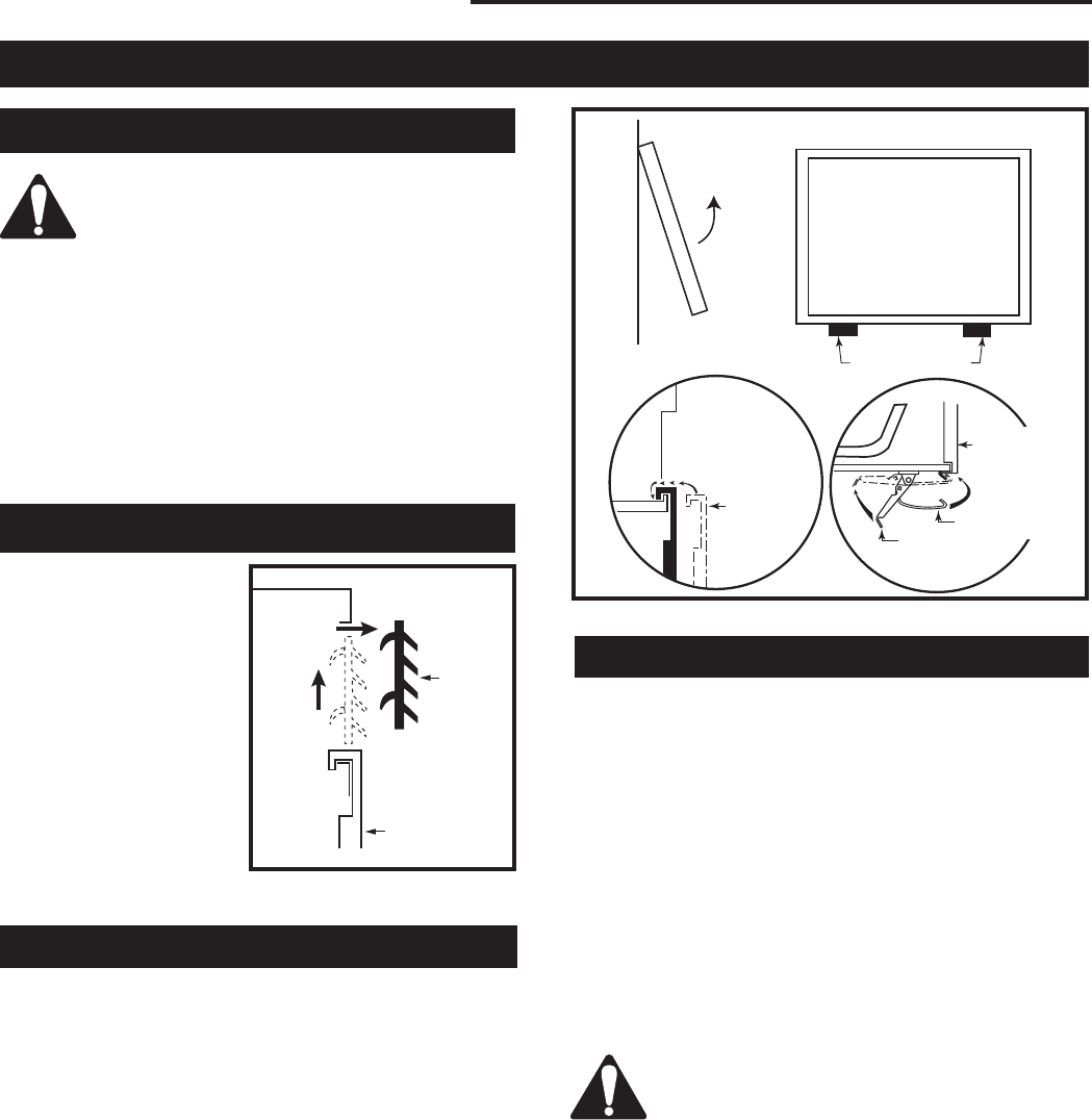
Check fireplace to make sure it is levelled
and properly positioned.
To mount the appliance:
1. Choose the location.
2. This unit comes with four (4) flanges pre-mounted
on both sides of the fireplace to allow two different
drywall thicknesses to be used. Flange “A” is for
1/2” drywall while flange “B” is for 5/8” drywall.
3. Bend the desired flanges out 90° on both sides of
the fireplace. Slide the fireplace into the framed
opening until the flanges contact the front surfaces
of the framing. Level the unit and secure it firmly in
place.
FP1544
nail flange
1/05
Fig. 4 Nailing flanges.
Flange Drywall
Position Depth
A 1/2” / 13 mm
B 5/8” / 16 mm
Flange Location for
Desired Drywall Depth
FP1539
AB
33LDVR units: GFRN2I0, GFRL2I0, GFRE2I0
36LDVR units: GFRN2J0, GFRL2J0, GFRE2J0
39LDVR units: GFRN2K0, GFRE2K0
43LDVR units: GFRN2N0, GFRE2N0
*Using conversion kit
7
LDVR Series Direct Vent Gas Fireplace
10007317
Installation
1. Thread the wiring through the holes on the end
panels of the fireplace. Take care not to cut the wire
or insulation on metal edges. Route the wire to a
conveniently located receptacle box.
2. Attach the wire to the ON/OFF switch and install the
switch into the receptacle box.
3. Connect the other ends of the wire to the gas control
valve. (Fig. 6)
The gas pipeline can be brought in through the rear
of the appliance as well as the bottom. Knockouts are
provided on the bottom behind the valve to allow for the
gas pipe installation and testing of any gas connection.
It is most convenient to bring the gas line in from the
rear right side of the valve as this allows fan installation
or removal without disconnecting the gas line.
The gas line connection can be made with properly
tinned 3/8” copper tubing, 3/8” rigid pipe or an ap-
proved flex connector. Since some municipalities have
additional local codes, it is always best to consult your
local authority and the National Fuel Gas Code, ANSI
Z223.1/NFPA 54 in the USA or the CSA-B149.1 instal-
lation code.
Do not wire the remote ON/OFF wall switch
for the gas fireplace to the 120 volt power
supply.
Alternate Switch Location
The remote switch can be installed on the front/side
of the access door. Simply mount the switch to the
bracket provided and screw the bracket to either side
of the frame, lining up the screws with the pre-punched
holes. (Fig. 7)
The gas control is equipped with a captured screw type
pressure test point, therefore it is not necessary to pro-
vide a 1/8” test point up stream of the control.
When using copper or flex connector use only approved
fittings. Always provide a union when using black iron
pipe so the gas line can be easily disconnected for
burner or fan servicing. See gas specification for pres-
sure details and ratings.
The fireplace valve must not be subjected to any test
pressures exceeding 1/2 psi. Isolate or disconnect this
and any other gas appliance control from the gas line
when pressure testing.
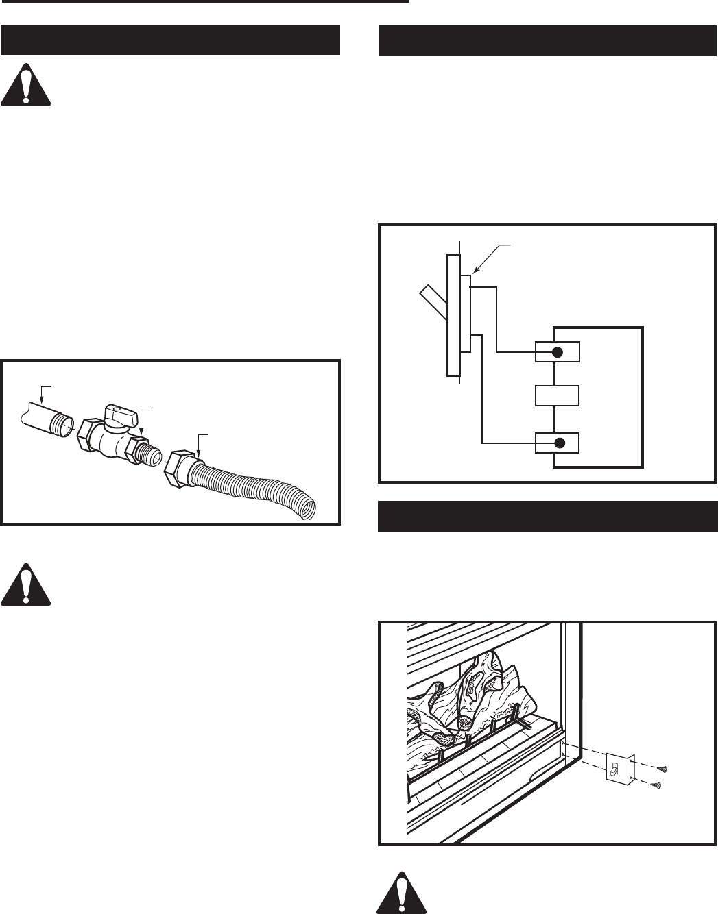
Gas Line Installation Remote ON/OFF Switch
When purging the gas lines, the front win-
dow frame assembly must be removed.
Always check for gas leaks with a mild
soap and water solution. Do not use an
open flame for leak testing.
FP297A
INSTA VENT FREE
UVHB26 GAS SUPPLY
7/1/98
FP297A
1/2” Gas Supply
1/2” NPT x 1/2” Flare Shut-
off Valve
3/8” Flex Line
(From Valve)
Fig. 5 Typical gas supply installation.
FP1024
alternate
remote switch
location
1/27/00 djt
FP1024
Fig. 7 Alternate switch location.
TP
TH
TP
TH
FP1224
Remote switch
11/02
Remote ON/OFF Switch
or Thermostat
or Remote Control
Gas
Control
Valve
FP1224
Fig. 6 Remote switch wiring diagram.
8
LDVR Series Direct Vent Gas Fireplace
10007317
The fireplace, when installed, must be
electrically connected and grounded in
accordance with local codes or, in the ab-
sence of local codes, with the current CSA
C22.1 Canadian Electrical Code.
For USA installations follow local codes
and the national electrical code ANSI/
NFPA No. 70.
It is strongly suggested that the wiring of
the EB-1 Electrical Junction Box be carried
out by a licensed electrician.
Ensure that the power to the supply line
has been disconnected before commenc-
ing this procedure.
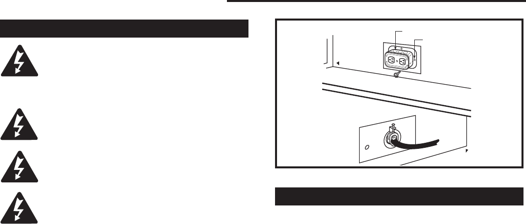
The EB-1 Electrical junction box has been fitted stand-
ard on this model to allow for the easy connection of an
optional fan kit.
To connect the EB-1 box to the house electrical supply
follow the steps below.
1. Unscrew the retaining screw from the EB-1 base
plate and remove the EB-1 assembly from the
appliance. (Fig. 8)
2. Remove the front cover of the EB-1 box.
3. Remove the plug socket assembly from the EB-1
box.
4. Feed the supply line in through the EB-1 opening in
the side of the appliance and then through the back
of the EB-1 assembly. (Fig. 8)
5. Connect the black wire of the power supply line to
the brass screw (polarized) of the socket assembly.
6. Connect the white wire of the power line to the
chrome screw of the socket assembly.
7. Connect the ground wire of the supply line to the
green screw of the socket assembly.
8. Refit the socket assembly back into the electrical
box and replace the cover plate. Secure the cable
with the clamp on the outside of the EB-1 base
plate and refit the EB-1 assembly to the unit with the
screw removed in step 1.
This appliance may be fitted with a Synetek ignition
module.
Installation of the remote on/off starter switch or
wall thermostat on electronic ignition units.
1. Thread the wiring through the holes on the side
panels of the appliance. Take care not to cut the wire
or insulation on metal edges. Route the wire to a
conveniently located receptacle box.
2. Attach the wire to the ON/OFF switch and install the
switch into the receptacle box.
3. Connect the white wire from the wall switch or wall
thermostat to the white wire terminal from the elec-
tronic module. Connect the black wire from the wall
switch or the red wire from the wall thermostat, to
the red wire terminal from the electronic module.
Electronic Gas Control Valve
EB-1 Electrical Box
FP580
INSTA VENT FREE
EB1 JUNCTION BOX
11/18/97
OUTSIDE
INSIDE
BACK OF UNIT
FP580
Electrical Box
Retaining Screw
Fig. 8 EB-1 receptacle.
9
LDVR Series Direct Vent Gas Fireplace
10007317
Your fireplace is approved to be vented either through
the side wall, or vertically through the roof.
• Only CFM Corporation venting components specifi-
cally approved and labelled for this fireplace may be
used.
• Vent terminations shall not be recessed into a wall or
siding.
• Horizontal venting which incorporates the twist lock
pipe must be installed on a level plane without an
inclining or declining slope.
• Horizontal venting which incorporates the use of flex
venting shall have an inclining slope from the unit of
1” (25 mm) per 24” (610 mm).
General Venting
There must not be any obstruction such as bushes,
garden sheds, fences, decks or utility buildings within
24” (610mm) from the front of the termination hood.
Do not locate termination hood where excessive snow
or ice build up may occur. Be sure to check vent termi-
nation area after snow falls, and clear to prevent ac-
cidental blockage of venting system. When using snow
blowers, make sure snow is not directed towards vent
termination area.
Location of Vent Termination
It is imperative the vent termination be located observ-
ing the minimum clearances as shown on the next
page.
*Check with local codes or in absence of same with
CSAB149.1 Installation Codes (1991) for Canada or fol-
low the current National Fuel Gas Code, ANSI Z223.1/
NFPA 54 for installations in the USA.
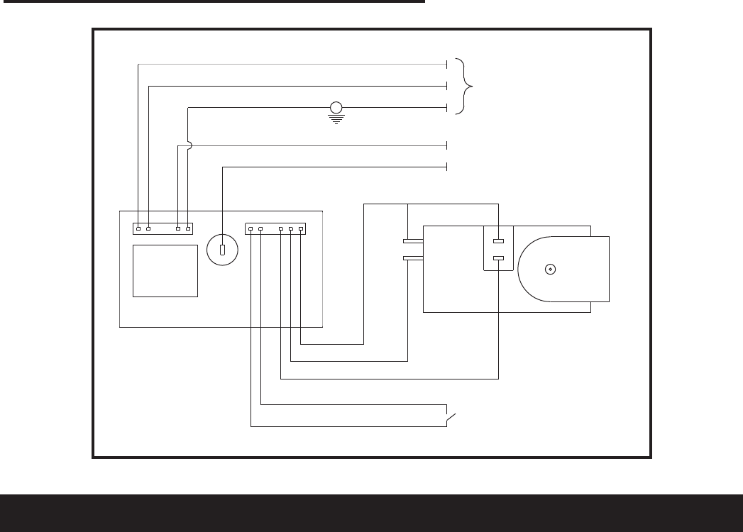
POWER CORD
CIRCUIT BOARD
ON/OFF SWITCH
OR
WALL THERMOSTAT
VALVE
RED
WHITE
BLUE
YELLOW
PURPLE
BLACK
WHITE
GREEN
PILOT SENSING
PILOT IGNITER
ORANGE
L1
L2
M
O
P
O
FP1571
SIT822
Synetek wiring
4/05
CLEAR
Fig. 9 SIT822 Valve with Synetek electronic control wiring diagram.
FP1571
10
LDVR Series Direct Vent Gas Fireplace
10007317
V
V
V
V
V
V
V
X
X
X
D
E
B
B
B
C
B
M
B
A
J
K
F
L
VENT TERMINATION AIR SUPPLY INLET AREA WHERE TERMINAL IS NOT PERMITTED
H
I
V
B
CFM145a
DV Termin Location
5/01/01 Rev. 12/05/01
sta
INSIDE
CORNER DETAIL
V
A
G
V
NN
V
V
G
G
A
CFM145a
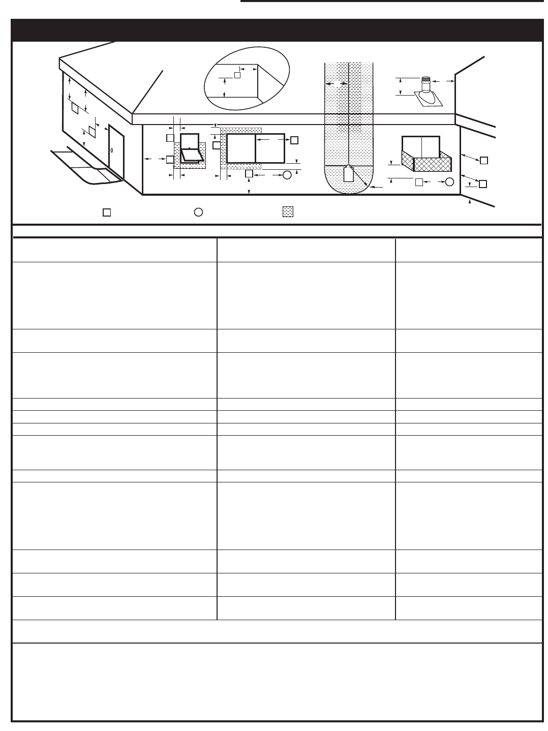
General Venting Information - Termination Location
A = Clearance above grade, veranda, porch, 12” (30cm) 12” (30cm)
deck, or balcony
B = Clearance to window or door that may be 6” (15cm) for appliances 6” (15cm) for appliances
opened < 10,000Btuh (3kW), 12” (30cm) < 10,000 Btuh (3kW), 9”
for appliances > 10,000 Btuh (3kW) and (23cm) for appliances > 10,000
< 100,000 Btuh (30kW), 36” (91cm) Btuh (3kW) and < 50,000 Btuh
for appliances > 100,000 Btuh (30kW) (15kW), 12” (30cm) for
appliances > 50,000 Btuh (15kW)
C = Clearance to permanently closed window 12” (305mm) recommended to 12” (305mm) recommended to
prevent window condensation prevent window condensation
D = Vertical clearance to ventilated soffit located
above the terminal within a horizontal 18” (458mm) 18” (458mm)
distance of 2ʼ (610mm) from the center
line of the terminal
E = Clearance to unventilated soffit 12” (305mm) 12” (305mm)
F = Clearance to outside corner see next page see next page
G = Clearance to inside corner (see next page) see next page see next page
H = Clearance to each inside of center line 3ʼ (91cm) within a height of 15ʼ (5m) 3ʼ (91cm) within a height of 15ʼ
extended above meter/regulator assembly above the meter/regulator assembly (5m) above the meter/regulator
assy
I = Clearance to service regulator vent outlet 3ʼ (91cm) 3ʼ (91cm)
J = Clearance to nonmechanical air supply inlet 6” (15cm) for appliances < 10,000 6” (15cm) for appliances
to building or the combustion air inlet to any Btuh (3kW), 12” (30cm) for < 10,000 Btuh (3kW), 9”
other appliances appliances > 10,000 Btuh (3kW) and (23cm) for appliances > 10,000
< 100,000 Btuh (30kW), 36” (91cm) Btuh (3kW) and < 50,000 Btuh
for appliances > 100,000 Btuh (30kW) (15kW), 12” (30cm) for
appliances > 50,000 Btuh (15kW)
K = Clearance to a mechanical air supply inlet 6ʼ (1.83m) 3ʼ (91cm) above if within 10
feet (3m) horizontally
L = Clearance above paved sidewalk or paved 7ʼ (2.13m)† 7ʼ (2.13m)†
driveway located on public property
M = Clearance under veranda, porch, deck or 12” (30cm)‡ 12” (30cm)‡
balcony
N = Clearance above a roof shall extend a minimum of 24” (610mm) above the highest point when it passes through the roof
surface, and any other obstruction within a horizontal distance of 18” (450mm).
1 In accordance with the current CSA-B149 Installation Codes
2 In accordance with the current ANSI Z223.1/NFPA 54 National Fuel Gas Codes
† A vent shall not terminate directly above a sidewalk or paved driveway which is located between two single family dwellings and
serves both dwellings
‡ only permitted if veranda, porch, deck or balcony is fully open on a minimum 2 sides beneath the floor:
NOTE: 1. Local codes or regulations may require different clearances.
2. The special venting system used on Direct Vent Stoves are certified as part of the appliance, with clearances tested and
approved by the listing agency.
Canadian Installations1 US Installations2
11
LDVR Series Direct Vent Gas Fireplace
10007317
Outside Corner
Inside Corner
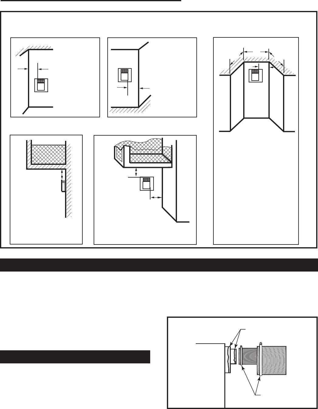
Termination Clearances
Termination clearances for buildings with combustible and noncombustible exteriors.
A =
Combustible
6"(152mm)
Noncombustible
2"(50mm)
B =
Combustible
6"(152mm)
Noncombustible
2"(50mm)
A
Balcony -
with no side wall
G =
Combustible &
Noncombustible
12"(305mm)
G
Balcony -
with perpendicular side wall
H = 24"(610mm)
J = 20"(508mm)
H
J
B
Recessed Location
C = Maximum depth of 48"
(1219mm) for recessed
location.
D = Minimum width for back wall
of a recessed location.
Combustible 38"(965mm)
Noncombustible 24"(610mm)
E = Clearance from corner in
recessed location.
Combustible 6"(152mm)
Noncombustible 2"(50mm)
C
D
C
E
V
V
Combustible &
Noncombustible
V
V
V
General Information Assembling Vent Pipes
Canadian Installations:
Venting system must be installed in accordance with the
current CSA-B149.1 installation code.
USA Installations:
The venting system must conform with local codes and/
or the current National Fuel Gas code ANSI Z223.1/
NFPA 54.
Only venting components manufactured by CFM Corpo-
ration can be used in Direct Vent systems.
Flex Vent Pipes
Before joining the flex vent pipe to the unit, apply a
bead of high temperature sealant* (provided) to the 4”
pipe exiting the fireplace. Secure flex vent piep in place
with a hose clamp (provided).
*Be sure the flex pipe overlaps at least 1” (25mm) onto
the collars of the fireplace and termination. If the ter-
mination has an internal bead, be sure to overlap and
secure 1” (25mm) past the bead.
584-15
Fig. 10 Termination clearances.
* Be sure the vent is actually crushed before proceed-
ing. Apply a tug to be sure the vent will not slip off the
collars.
Repeat process with 7” flex vent pipe. The same proce-
dure must be performed on the vent side.
FP1471
flex vent
Apply High Temperature
Sealant
Hose Clamp
FP1471
Fig. 11 Apply high temperature sealant to 4” and 7” pipes.
12
LDVR Series Direct Vent Gas Fireplace
10007317
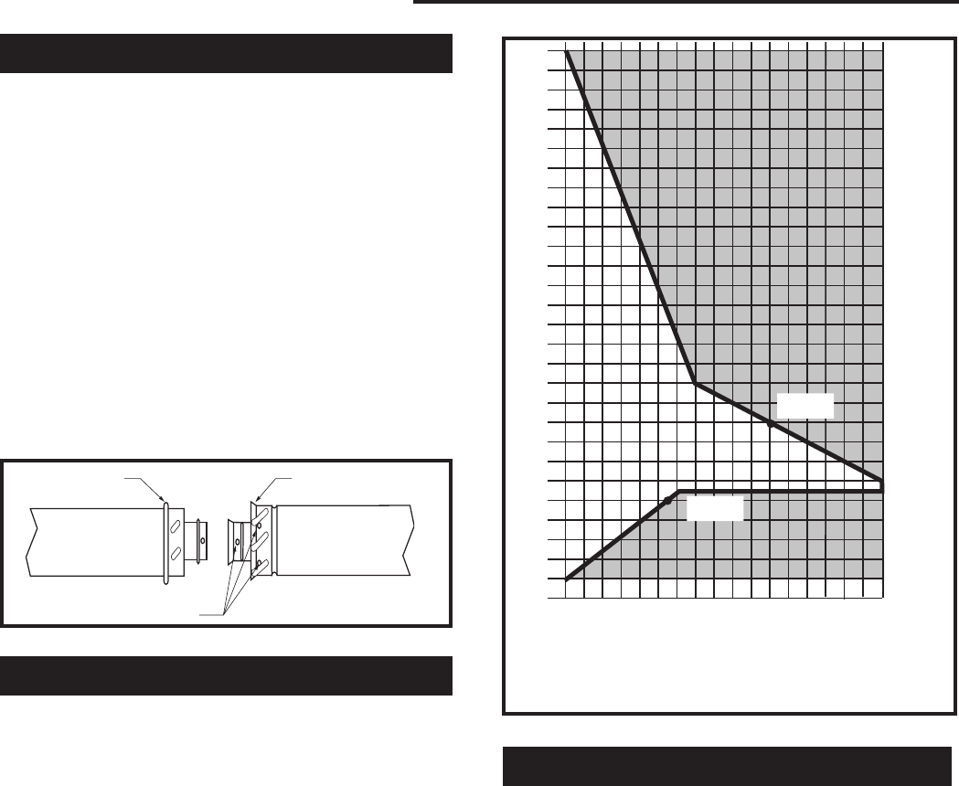
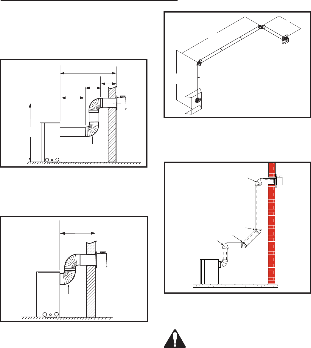
The vent chart should be read in conjunction with the
following vent installation instructions to determine the
relationship of the vertical and horizontal dimensions of
the vent system.
1. Determine the height of the center of the horizontal
vent pipe exiting through the outer wall. Using this
dimension on the Sidewall Vent Graph (Fig. 13)
locate the point intersecting with slanted graph line.
2. From the point of this intersection, draw a vertical
line to the bottom of the graph.
3. Select the indicated dimension, and position the
fireplace in accordance with same.
Example A:
If the vertical dimension from the floor of the
fireplace is 11ʼ (3.4m) the horizontal run to the face
of the outer wall must not exceed 14ʼ (4.3m).
Example B:
If the vertical dimension from the floor of the unit is
7ʼ (2.14m), the horizontal run to the face of the outer
wall must not exceed 8¹⁄₂ʼ (2.6m).
How to Use the Vent Graph
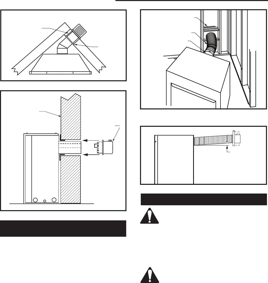
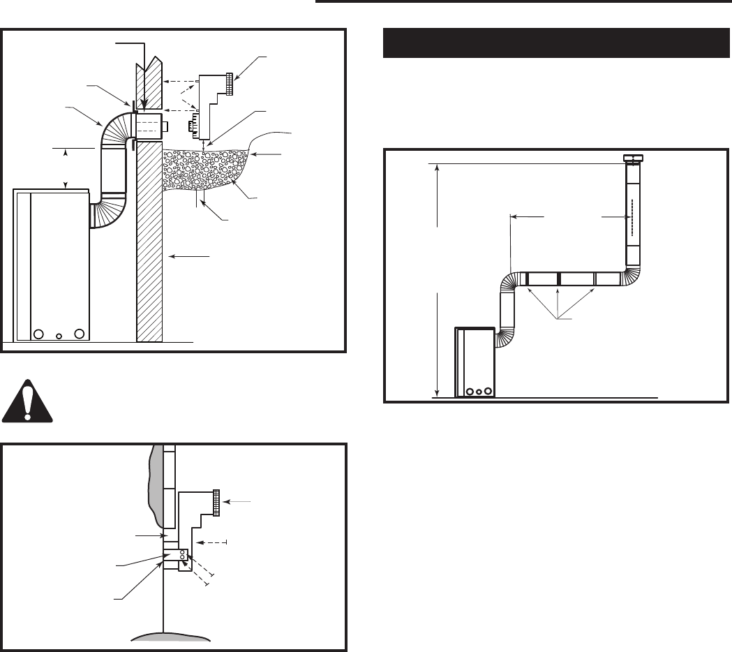
Rear Wall Venting Applications
When installed as a rear vent unit this appliance may
be vented directly to a termination located on the rear
wall behind the appliance.
• Only CFM Corporation venting components are
approved to be used in these applications. (Refer to
“Venting Components” listed for different installation
requirements)
• The maximum horizontal distance between the rear
of the appliance (or end of the transition elbow in a
corner application) and the outside face of the rear
wall is 20” (508mm). (Fig. 14)
• Only one 45° elbow is allowed in these installations.
• Minimum clearances between vent pipe and com-
bustible materials are as follows:
Top - 2” (50mm)
Sides - 1” (25mm)
Bottom - 1” (25mm)
Horizontal dimension from the outside face of the
wall to the center of the fireplace vent flange
Sidewall vent graph showing the relationship between vertical
and horizontal dimensions for a Direct Vent flue system.
Vertical dimension from the floor of the unit
to the center of the horizontal vent pipe
3
4
5
6
7
8
9
10
11
12
13
14
15
16
17
18
19
20
21
22
23
24
25
26
27
28
29
30
3 4 5 6 7 8 9 10 11 12 13 14 15 16 17 18 19 20
eg: A
eg: B
CFM102
DV Graphic
9/28/00 sta
Fig. 13 Sidewall venting graph. (Dimensions in feet)
TWL100
Twist Lock Pipe
3/12/99 djt
Male End Female End
Screw Holes TWL100
Fig. 12 Twist-lock pipe joints.
Twist Lock Pipes
When using CFM Corporation twist-lock pipe it is not
necessary to use sealant on the joints. The only areas
of the venting system that need to be sealed with high
temperature silicone sealant are the collars on the
fireplace and termination, and the sliding joint of any
telescopic vent section used in the system.
To join the twist lock pipes together, simply align the
beads of the male end with the grooves of the female
end, then while bringing the pipe together, twist the pipe
until the flange on the female end contacts the external
flange on the male end. It is recommended that you
secure the joints with three (3) sheet metal screws,
however this is not mandatory with twist lock pipe.
To make it easier to assemble the joints we suggest
putting a lubricant (Vaseline or similar) on the male end
of the twist lock pipe prior to assembly.
13
LDVR Series Direct Vent Gas Fireplace
10007317
DVR584-600
Rear vent no elbows
2/99 djt
20"
(508mm)
Top View
Straight Venting
FP836
Rear Vent-Top View
11/21/98
20"
(508mm)
Max.
REAR VENT-TOP VIEW
20"
(508mm)
Max.
Top View
Rear Vent Corner Installation
Fig. 14 Rear vent applications, one 45° elbow.
45° 45°
Rear Wall Installation
Twist Lock Pipe
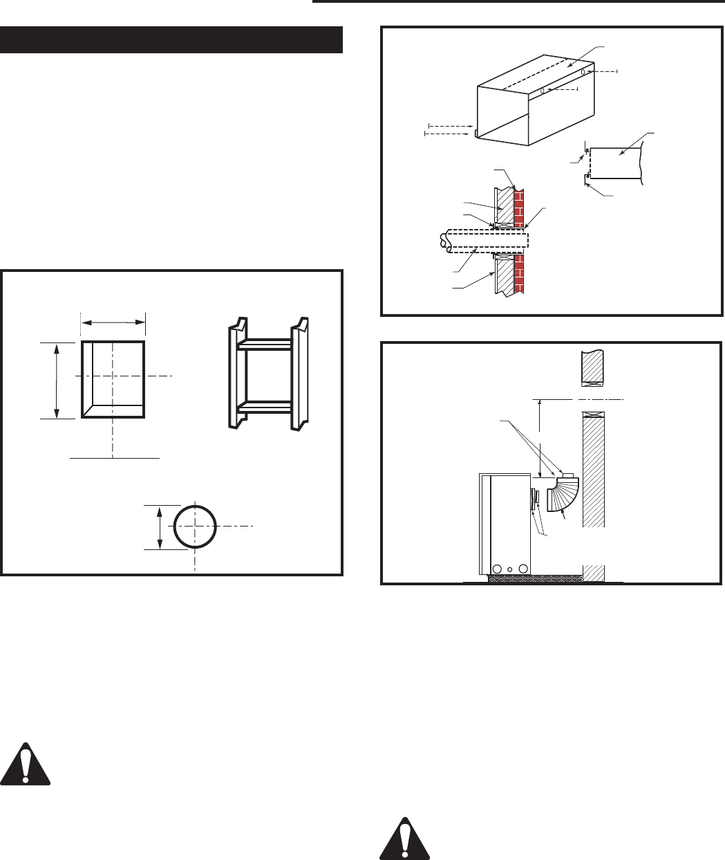
STEP 1
Locate vent opening on the wall. To locate hole center
consult with appropriate fireplace dimensions, Page 4.
Frame as shown below.
NOTE: When using flex vent, the opening will have to
be measured according to the 1/2” (13 mm) rise in 12”
(305 mm) vertical run.
Combustible Walls (Fig. 15): Cut a 10³⁄₈”H x 9³⁄₈” W
(264 x 240mm) hole through the exterior wall and frame
as shown.
Noncombustible Walls (Fig. 15): Hole opening must
be 7¹⁄₂” (190mm) in diameter.
STEP 2
Measure wall thickness and cut zero clearance sleeve
parts to proper length (MAXIMUM 12”/305mm). Assem-
ble sleeve and attach to firestop with #8 sheet metal
screws (supplied). (Fig. 16)
VO584-100
Vent Opening
2/99 djt
Vent Opening for Combustible Wall
9³⁄₈”
(240mm)
10³⁄₈”
(264mm)
Fireplace Hearth
Framing
Detail
Opening for Noncombustible Wall
7¹⁄₂”
(190mm)
VO584-100
Fig. 15 Locate vent opening on wall.
ZCS101
Zero Clearance Sleeve
3/11/99 djt
Max. Length
12” (305mm)
#8 Screws (2)
#8 Screws
(2)
Adjustable
Zero Clearance
Sleeve
#8
Screws
(2)
Adjustable Zero Clearance Sleeve ZCS101
Fig. 16 Adjustable zero clearance sleeve.
Firestop
STEP 3
Measure from the fireplace collar or elbow face to face
of outside wall (add 2” for vent pipe overlap). Mark
pipes and cut to length. It is very important that the two
pipes are flush with the outside wall once the fireplace
is in its final location. (Fig. 17)
STEP 4
Slip 4” and 7” pipes onto respective flue collars. Make
sure to fix to the fireplace collar the 4” pipe with three
(3) screws before fixing the 7” pipe on the 7” collar.
Both pipes must be on a level plane. (Fig 18)
STEP 5
Guide the vent termination 4” collar into the 4” pipe then
the 7” collar into the 7” pipe. Do not force the venting
into position. If the pipes do not line up with the termi-
nation collars, disassemble pipes and reattach to the
fireplace collar. (Fig. 18)
STEP 6
Secure fireplace to floor through floor holes and adjust-
able frame drywall strip (nailing flange) to frame. (Refer
to Framing & Finishing Section).
14
LDVR Series Direct Vent Gas Fireplace
10007317
CFM133
DVR Series Typical corner install
2/26/01 sta
Zero
Clearance
Sleeve
Firestop
CFM133
Fig. 17 Firestop and zero clearance sleeve in place.
FP1005
Side View Vent Termination
1/25/00 djt
Finished Wall
Vent Termi-
nation
FP1005
Fig. 18 Side view of final unit location.
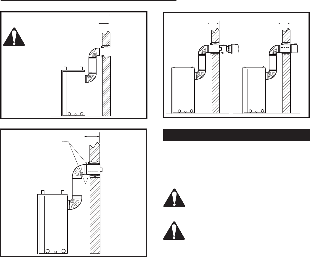
Vertical Sidewall Applications
Since it is very important that the vent-
ing system maintain its balance between
the combustion air intake and the flue
gas exhaust, certain limitations as to vent
configurations apply and must be strictly
adhered to.
The Vent Graph shows the relationship between vertical
and horizontal side wall venting and will help to deter-
mine the various dimensions allowable.
Minimum clearance between vent pipes
and combustible materials is 1”(25mm) on
top, bottom and sides unless otherwise
noted.
When vent termination exits through foundations less
than 20” below siding outcrop, the vent pipe must
flush up with the siding. It is always best to locate the
fireplace in such a way that minimizes the number of
offsets and horizontal vent length.
The horizontal vent run refers to the total length of vent
pipe from the flue collar of the fireplace to the face of
the outer wall.
Rear Wall Vent Installations -
Flex Vent Pipe
Follow Steps 1 and 2 on Page 13.
Step 3
Install the 4” (102mm) flex vent pipe to the appliance
collars described in “General Information Assembling
Vent Pipes”, Page 11. If the installation requires a 45°
angle, grasp the vent pipe close to the appliance collar
and bend to 45°. DO NOT exceed 45°. (Fig. 19)
Install the 7” vent pipe in the same manner as Step 2.
NOTE: There must be a 1” (25mm) rise in a 24”
(610mm) length of flex vent.
Step 4
Assemble the flex vent to the collars on the termination
as you did on the appliance.
FP1473
corner flex install
4/04 djt
Termination
Flex Section
Appliance Collars
FP1473
Fig. 19 Grasp the vent pipe close to the collar and bend to
45° angle. Do not exceed 45°.
FP1472
rise in length
4/04 djt
FP1472
Fig. 20 There must be a 1/2” rise per foot length.
Rise
15
LDVR Series Direct Vent Gas Fireplace
10007317
•IMPORTANT• Minimum clearance between vent
pipes and
combustible materials is one (1”) inch (25 mm)
on bottom, sides and top.
Twist Lock Vent Starter Kit 7TDVSK, plus
Transition Elbow 7TDVRT90 must be used
in Vertical Sidewall installations. The 4”
pipe must be centered inside the 7” pipe
coming off the transition elbow.
Canadian & USA Installations:
The venting system must conform with local codes, or
in the absence of local codes, with National Fuel Gas
Code, ANSI Z223.1/NFPA 54 - latest edition, or CSA
B149.1 Installation Code.
Only CFM Corporation venting components specifically
approved and labelled for this fireplace may be used.
Maximum
3' (914mm)
7TDVRT90
Elbow
CFM142
Venting
2/2/01 sta
CFM142
Fig. 22 Maximum horizontal vent run.
18” (45cm). This does not apply if the 45° elbows
are installed on the vertical part of the vent system.
• The maximum number of elbow degrees in a system
is 270°. (Fig. 24)
Example: According to the chart the maximum hori-
zontal vent length in a system with a 7.5ʼ (2.3m) ver-
tical rise is 20ʼ (6 m) and if a 90° elbow is required in
the horizontal vent it must be reduced to 17ʼ (5.2 m).
In Figure 23 Dimension A plus B must not be greater
than 17ʼ (5.2 m).
• The maximum number of 45° elbows permitted per
side wall installation is two (2). These elbows can be
installed in either the vertical or horizontal run.
• For each 45° elbow installed in the horizontal run,
the length of the horizontal run MUST be reduced by
V584-201
Horizontal Run
2/99 djt
10 ft.
(3048 mm)
7 ft. 6 in.
(2286 mm)
7 ft.
(2134 mm)
CFM147
Fig. 23 Maximum vent run with elbows.
90° Elbow = 3 ft.
A + B = 17 ft. (Max.)
CFM141
2/2/01 sta
Maximum
20 ft. (6.1m)
7.5'
(2.3m)
7TDVRT90
Elbow
15 ft.
(4572mm)
48"
(1.2m)
12"
(305mm)
Vertical Dimension
7¹⁄₂ʼ Minimum When
Horizontal Run is
20ʼ
CFM141
Fig. 21 Maximum number of 90° elbows is three (3).
Horizontal plane means no vertical rise exists on this
portion of the vent assembly.
• The maximum horizontal vent run is 20 ft. (6.1m)
when the vertical vent rise is 7¹⁄₂ ft. (2.3m). (Fig. 21)
• The maximum number of 90° elbows per side wall
installation is three (3).
• If a 90° elbow is used in the horizontal vent run
(level height maintained) the maximum horizontal
vent length is reduced by 36” (914 mm). (Fig. 22)
This does not apply if the 90° elbows are used to
increase or redirect a vertical rise. (Fig. 23)
1
2
3
4
1 + 2 + 3 + 4 = 270o
CFM132
Insert Rear Vent Sidewall
2/26/01 sta
CFM132
Fig. 24 Maximum number of elbows.
Example:
Elbow 1 = 90˚
Elbow 2 = 45˚
Elbow 3 = 45˚
Elbow 4 = 90˚
Total angular variation = 270˚
16
LDVR Series Direct Vent Gas Fireplace
10007317
Vertical Sidewall Installation
STEP 1
Locate vent opening on the wall. It may be necessary
to first position the fireplace and measure to obtain hole
location. Depending on whether the wall is combustible
or noncombustible, cut opening to size. (Fig. 25)
For combustible walls first frame in opening.
Combustible Walls (Fig. 25): Cut a 9³⁄₈”H x 9³⁄₈” W
(240 x 240mm) hole through the exterior wall and
frame.
Noncombustible Walls (Fig. 25): Hole opening must
be 7.5” (190mm) in diameter.
VO584-100
Vent Opening
2/99 djt
Vent Opening for Combustible Wall
9³⁄₈”
(240mm)
9³⁄₈”
(240mm)
Fireplace Hearth
Framing Detail
Opening for Noncombustible Wall
7¹⁄₂”
(190mm)
VO584-100
Fig. 25 Locate vent opening on wall.
STEP 2
Measure wall thickness and cut adjustable zero
clearance sleeve parts to proper length (MAXIMUM
12”/305mm). (Fig. 26) Adjust sleeve to minimum (9³⁄₈” x
9³⁄₈” and attach to firestop with #8 sheet metal screws
(supplied). Assemble sleeve and attach to firestop with
#8 sheet metal screws (supplied). Install firestop as-
sembly.
Zero clearance sleeve is only required for
combustible walls.
STEP 3
Apply a bead of high temperature sealant to the inner
and outer flue collars of the fireplace and using ap-
propriate venting component(s) attach to fireplace with
three (3) screws. (Fig. 27) Follow with the installation
of the inner and outer elbow. Again secure joints with
three (3) sheet metal screws. Wipe off any excess high
temperature sealant.
CFM135
Zero Clearance Sleeve
2/26/01 sta
Adjustable Zero Clear-
ance Sleeve Maximum Length
12” (305mm)
#8 Screws (2)
Adjust-
able Zero
Clearance
Sleeve
Firestop
#8 Screws
(2)
Wall Exterior
Wood Framing
Firestop
Vent Pipe
Drywall
Zero Clearance
Sleeve Flush with
Wall Exterior
CFM135
Fig. 26 Locate vent opening on wall.
#8 Screws (2)
STEP 4
Measure the horizontal length requirement including a
2” (50mm) overlap, i.e. from the elbow to the outside
wall finish plus 2”, or the distance required if installing a
second 90° elbow. (Fig. 28)
STEP 5
Use appropriate length of pipe section - telescopic or
fixed - and install the horizontal vent sections. The 20”
(508mm) section of pipe which goes through the wall is
packaged with the 7TDVSK starter kit, and can be cut
to suit if necessary. (Fig. 29)
Sealing vent pipe and firestop gaps with
high temperature sealant will restrict cold
air being drawn in around fireplace.
CFM143
2/2/01 sta
Ensure Pipes are
Concentric
Bead of Seal-
ant
(If necessary)
CFM143
Fig. 27 Apply sealant to inner and outer pipe.
17
LDVR Series Direct Vent Gas Fireplace
10007317
STEP 6
Apply high temperature sealant to 4” (102 mm) and 7”
(178 mm) collars or the termination one inch away from
the end. Guide the vent terminationʼs 4” and 7”
collars
into their respective vent pipes. Double check that the
vent pipes overlap the collars by 2” (50 mm). Secure the
termination to the wall with screws provided and caulk
around the wall plate to weatherproof. (Fig. 30)
STEP 7
Support the horizontal pipes every 36” (914 mm) with
metal pipe straps. Make sure that the horizontal vent
pipe is installed on a level horizontal plane.
STEP 8
Re-check the fireplace to make sure that it is levelled,
properly positioned, and nailed or screwed to the floor.
If applied, the fireplaces adjustable frame drywall strips
(nailing flanges) should be fastened. Refer to “Framing
& Finishing”.
CFM137
Rear Vent length
2/26/01 sta
X
High
Temperature Sealant
CFM137
Fig. 29 Apply high temperature sealant.
CFM138
4", 7" collar
2/26/01 sta
XX
CFM138
Fig. 30 Horizontal length requirement.
CFM136
Rear Vent horizontal length
2/26/01 sta
X
Always install hori-
zontal venting on a
level plane.
CFM136
Fig. 28 Measure horizontal length including 2” overlap.
Below Grade Installations
When it is not possible to meet the required vent ter-
minal clearances of 12” (305mm) above grade level a
snorkel vent kit #7TDVSNORK is required. It allows
installation depth of down to 7” (178 mm) below grade
level. The 7” is measured from the center of the hori-
zontal vent pipe as it penetrates through the wall.
If venting system is installed below
ground, we recommend a window well with
adequate and proper drainage.
Ensure sidewall venting clearances are observed.
The maximum horizontal run with 24”
vertical rise is 36” (914 mm) from the
back of the fireplace to the face of the
exterior wall. See vent graph (Page 12) for
extended horizontal run if the vertical rise
exceeds 24” (610 mm).
1. Establish vent hole through the wall. (Fig. 25)
2. Remove soil to a depth of approximately 16”
(406mm) below base of snorkel. Install window
well (not supplied). Refill hole with 12” (305 mm) of
coarse gravel leaving a clearance of approximately
4” (102 mm) below snorkel. (Fig. 31)
3. Install vent system. See Page 13, Steps 2 through 5.
4. Ensure a watertight seal is made around the vent
pipe coming through the wall.
5. Apply high temperature sealant caulking (supplied)
around the 4” and 7” snorkel collars.
6. Slide into the vent pipe and secure to the wall.
7. Level the soil to maintain a 4” (102 mm) clearance
below snorkel. (Fig. 31)
18
LDVR Series Direct Vent Gas Fireplace
10007317
Do not back fill around snorkel. A
clearance of at least 4” (102mm) must be
maintained between the snorkel and the
soil.
BG401
Snorkel
2/10/99 djt
Foundation Recess
Snorkel
Wall Screws
Recess Brackets
Watertight Seal
Around Pipe Sheet Metal
Screws
BG401
Fig. 32 Snorkel installation, recessed foundation.
BG400
Below grade installation
2/10/99 djt
10/19/99 added standoffs
24" (610mm)
Minimum*
Zero Clearance
Sleeve
(if required)
Firestop
7” Pipe
7TDVSNORK
(Snorkel)
4” (102mm)
Clearance
Min.
Window
Well
Gravel
Drain
Foundation Wall
BG400
Fig. 31 Below grade installation.
*A minimum of 24” (608mm)
vertical pipe must be installed
when using 7TDVSNORK Kit.
If the foundation is recessed, use recess brackets (not
supplied) for securing lower portion of the snorkel.
Fasten brackets to wall first, then secure to snorkel
with self drilling #8 x 1/2 sheet metal screws. It will be
necessary to extend vent pipes out as far as protruding
wall face. (Fig. 32)
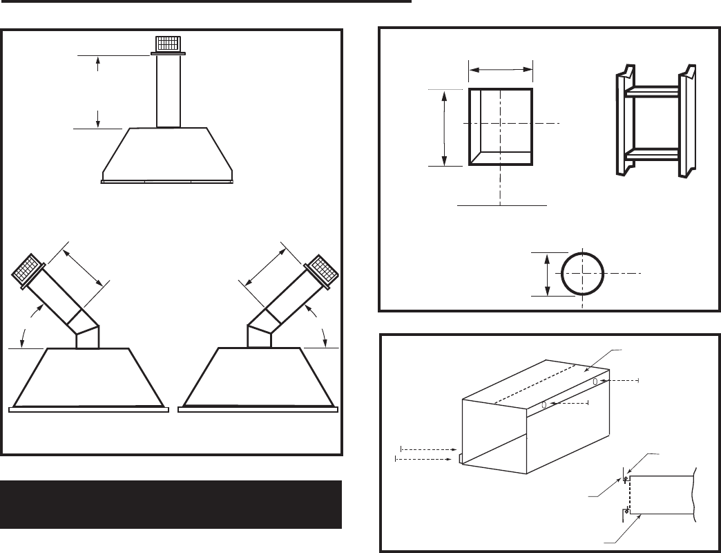
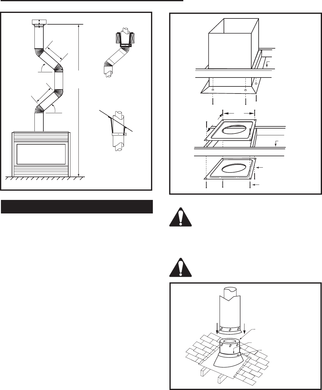
This Gas Fireplace has been approved for:
1. Vertical installations up to 40ʼ (12 m) in height. Up to
10ʼ (3 m) horizontal vent run can be installed within
the vent system using a maximum of three 90°
elbows.
Vertical Through-the-Roof Applications
CFM148
Maximum
10ʼ
(3 m)
Minimum
8ʼ (2.4 m) /
Maximum
40ʼ (12 m) Vertical
Rise
CFM148
Pipe Straps Every
3ʼ (914 mm)
Fig. 33 Support straps for horizontal runs.
This Gas Fireplace has been approved for:
1. Vertical installations up to 40ʼ (12 m) in height. Up to
10ʼ (3 m) horizontal vent run can be installed within
the vent system using a maximum of three 90°
elbows.
2. Up to two 45° elbows may be used within the
horizontal run. For each 45° elbow used on the
horizontal level the maximum horizontal length must
be reduced by 18” (457 mm).
Example: Maximum horizontal length
0 x 45° elbows = 10ʼ (3 m)
1 x 45° elbows = 8¹⁄₂ʼ (2.6 m)
2 x 45° elbows = 7ʼ (2.1 m)
3. A minimum of an 8ʼ vertical rise.
4. Two sets of 45° elbows offsets within these vertical
installations. From 0 to a maximum of 8ʼ (2.4 m) of
vent pipe can be used between elbows. (Fig. 34)
5. 7DVCS must be used to support offsets. (Fig. 34)
This application will require that you first determine
the roof pitch and use the appropriate 7DVSKV (A, B
or F). (Refer to Venting Components List, Page 21)
19
LDVR Series Direct Vent Gas Fireplace
10007317
Vertical Through-the-Roof Installation
CFM100
Firestop-Vertical
09/20/00
11"
11"
Joist
Joist
Firestop Spacer
Nails (4)
Upper Floor
Attic Insulation
Shield
Ceiling Instal-
lation
CFM100
Fig. 35 Place firestop spacer(s) and secure.
FP1021
Typical vertical
through the roof
application
3/26/00 djt
Max.
8ʼ
(2.4m)
45°
Max.
8ʼ
(2.4m)
45°
40ʼ
(12m)
Typical
Ceiling
Support
Application
Typical Roof
Support Ap-
plication
FP1021
Typical Offset Installation
Fig. 34 Typical vertical roof applications.
1. Locate your fireplace.
2. Plumb to center of the (4”) flue collar from ceiling
above and mark position.
3. Cut opening equal to 9³⁄₈” x 9³⁄₈” (240 x 240mm).
4. Proceed to plumb for additional openings through
the roof. In all cases, the opening must provide a
minimum of 1 inch clearance to the vent pipe, i.e.,
the hole must be at least 9³⁄₈” x 9³⁄₈” (240 x 240mm).
5. Place fireplace into position.
6. Place firestop(s) #7DVFS or Attic Insulation Shield
#7DVAIS into position and secure. (Fig. 35)
7. Install roof support (Fig. 36 & 37) and roof flashing
making sure upper flange is below the shingles. (Fig.
36)
8. Install appropriate pipe sections until the venting is
above the flashing. (Fig. 36)
9. Install storm collar and seal around the pipe.
10. Add additional vent lengths for proper height. (Fig
38)
11. Apply high temperature sealant to 4” and 7” collars
of vertical vent termination and install.
If there is room above ceiling level,
firestop spacer must be installed on both
the bottom and the top side of the ceiling
joists. If an attic is above ceiling level a
7DVAIS (Attic Insulation Shield) must be
installed. (Fig. 35)
The enlarged ends of the vent section
always face downward. (Fig. 36)
TWL101a
Twist Lock Pipe
2/8/99 djt
3 #5 Sheet Metal
Screws per Joint
Storm Collar
TWL101a
Fig. 36 Roof flashing.
Sealant
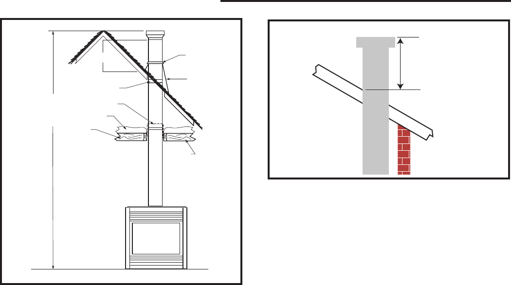
20
LDVR Series Direct Vent Gas Fireplace
10007317
FP1022
Typical Straight Up Installation
1/26/00 djt
40ʼ
(12m)
Storm Collar
Roof Flash-
ing
Vent
Termination
Roof
2ʼ Min.
Roof Support
Attic Insulation
Shield
Attic
Insulation
Joists
Joists
FP1022
Fig. 37 Typical straight-up installation.
Min.
2' (610 mm)
FP1185
Fig. 38 Minimum termination to roof clearance.
21
LDVR Series Direct Vent Gas Fireplace
10007317
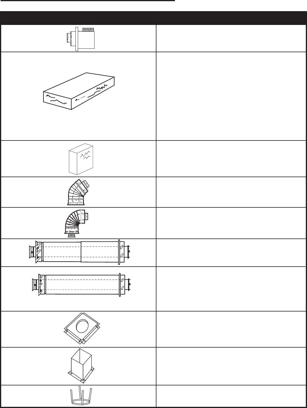
Venting Components
584G
Venting Components
Firestop spacer
2/25/99 djt
584H
Venting components
attic insulation shield
2/25/99 djt
584I
vent components
offset support
2/25/99 djt
584D
Vent Components
90 degree elbow
2/25/99 djt
10/20/99 twist lock
584C
Vent components
45 degree elbow
2/25/99 djt
10/20/99 twistlock
584A
venting components
rear vent term
4/6/99 djt
584E
Venting Components
Telescope vent
2/25/99 djt
10/20/99 twist lock
584F
Venting Components
Pipe sections
2/25/99 djt
10/20/99 twist lock
7TDVRVT - Through the wall Rear Vent Termination
Starter Kit -
Model 7TDVSK - Sidewall Venting (Twist Lock Pipe)
Model 7FDVSK - Sidewall Venting (Flex Vent Pipe)
Models 7TDVTK/TV - Hot Touch Termination Kits
Model 7TDVTVTK/TV - Cool Touch Termination Kit
Starter Kit - Model 7TDVSKV - Vertical Venting
for 7TDVSKV-A order 1/12 to 6/12 roof pitch
for 7TDVSKV-B order 7/12 to 12/12 roof pitch
for 7TDVSKV-F order flat roof
Starter Kit for Below Grade Installation
Model 7TDVSKS -Snorkel Kit (Twist Lock Pipe)
Model 7FDVSKS -Snorkel Kit (Flex Vent Pipe)
Starter Pipe
Model 7TDVP 20/8 - 24” Starter Pipe Bulk
Model 7FDVP 30/8 - 30” Flex Pipe Bulk
45o Elbow
7TDV45 for Rear Vent to Vertical Vent
or Vertical/Horizontal Offsets
90o Transition Elbow
7TDVRT90 for Rear Vent to Vertical Vent
90° Elbow
7TDV90 Vertical/Horizontal Offset
Telescopic vent sections
7TDVP1117 -11” to 17” adjustable length
7TDVP3567 -35” to 67” adjustable length
Pipe sections for vertical or horizontal venting
Model 7TDVP8” - 4 per box
Model 7TDVP12” - 4 per box
Model 7TDVP24” - 4 per box
Model 7TDVP36”
Model 7TDVP48”
Firestop Spacer
Model 7DVFS
Attic Insulation Shield
Model 7DVAIS
Vertical/Horizontal Combination Offset Support
Model 7DVCS
584B
Vent components
Starter Kit
2/25/99 djt
22
LDVR Series Direct Vent Gas Fireplace
10007317
Only glass approved by CFM Specialty
Home Products should be used on this
fireplace.
The top louvre panel
is removed by lifting
the panel vertically and
pulling it away from the
appliance. (Fig. 39) The
lower access door is
hinged along the bottom
edge and is folded
down to allow access.
1. Turn the fireplace OFF (including the pilot)
2. If the unit has been operating allow time for the
components to cool.
3. Remove the top louvre assembly.
4. Open the lower louvre panel.
5. Release the two clamps securing the lower edge of
the window frame assembly by pulling down on the
handles. (Fig. 40)
6. Tilt the window frame assembly out slightly at the
bottom, lift the window frame assembly up and away
from the fireplace.
7. To replace the window frame assembly reverse
the procedure.
It is necessary to periodically clean glass. During start-
up condensation, which is normal, forms on the inside
of the glass. This condensation causes lint, dust and
other airborne particles to cling to glass surface.
Also initial paint curing may deposit a slight film on
the glass. It is therefore recommended the glass be
cleaned two or three times with a non-ammonia based
household cleaner and warm water (We recommend
gas fireplace glass cleaner) within the first few weeks of
operation.
After the initial cleaning process the glass should be
cleaned two or three times during each operating
season depending on the environment in the house.
• The use of any non-approved replacement glass will
void all product warranties.
• Care must be taken to avoid breakage of the glass.
• Do not operate appliance with glass front
removed, cracked or broken.
• Replacement glass (complete with gasket) is
available through your CFM Specialty Home
Products dealer and should only be installed by
a licensed qualified service person.
Clean glass after first two weeks of
operation.
Do not clean glass when hot.
Do not use abrasive cleaners.
Do not strike or slam the glass.
Operating Instructions
Glass Information
Window Frame Assembly Removal
Glass Cleaning
Louvre Removal
1.
2.
FP1227
Louvre removal
11/02
Louvre
Glass Panel
FP1227
Fig. 39 Remove top louvre
assembly.
FP1228
remove glass frame
11/02
Lower Clamps
Window
Frame
Assembly Push
Clamp
Handle
Pull Clamp
Hook
Window
Frame
Assembly
FP1228
Fig. 40 Window frame assembly removal.
23
LDVR Series Direct Vent Gas Fireplace
10007317
1. Remove the top louvre assembly.
2. Open the bottom louvre.
3. Remove the window frame assembly.
4. Remove log box from inside firebox.
5. Unpack the logs from packaging and remove each
log from its wrapping material. Set aside the ember
and the lava rock bags.
As with all plastic bags - these are not toys
and should be kept away from children and
infants.
Installation of Logs, Lava Rock & Ember Material
Log Installation
33LDVR
1. Place rear log left (A41) on rear bracket (ensure the
notch on the left end locates against the bend up on
the left side of rear bracket.)
2. Place rear log right (A42) on rear bracket (ensure
the notch on the right end locates against the bend
up on the right side of rear bracket) and just rest the
cut out from front log onto the front support.
3. Place front log left (A43). Use the logʼs bottom hole
to locate it onto rear log left (A41) and just rest bot-
tom cut out log onto the front support.
4. Place top log center (A44). Use the logʼs bottom
hole to locate it onto the knob on the rear log right
(A42) and the top log center rest onto rear log left.
5. Place ember material on top of burner. Scatter the
ember material over the tiles on the front area of the
burner housing. (Fig. 48) Do not pack the ember
material. Separate it when unpacked and keep it
in a fluffy and loose condition for a more realistic
ember effect.
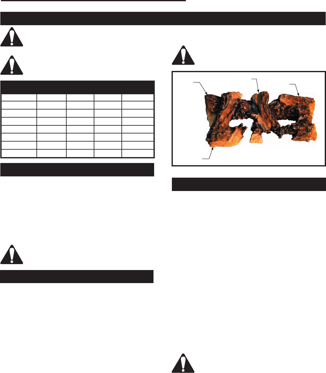
LG382
36LDV logs
1/05
Rear Left
(A41)
Top Center
(A44) Rear Right
(A42)
Front Left
(A43) LG382
Fig. 41 Correct log placement for 33LDVR.
36LDVR
1. Place rear log (B135) on rear bracket (ensure log
is seated properly to the bracket and located to the
two pins), so it will not move from side to side and is
firmly positioned on the bracket.
2. Place front left log (B136). Use the logʼs bottom hole
to locate it onto the front support and just rest on top
of the rear log.
3. Place front right log (B137). Use the logʼs bottom
hole to locate it onto the front support and the top
hole to the knob onto the rear log.
4. Place front center log (B138) on top of the two small
shelves at the front log support and between the left
and right logs.
5. Place ember material on top of burner. Scatter the
ember material over the tiles on the front area of the
burner housing. (Fig. 49) Do not pack the ember
material. Separate it when unpacked and keep it in a
fluffy and loose condition for a more realistic ember
effect.
6. Scatter the lava rock material around the firebox
base.
Do not place any of the lava rock material
on the burner housing assembly.
The logs are fragile and should be handled
with care. Keep the packaging material out
of the reach of children and dispose of the
material in a safe manner.
The individual logs can be easily identified
by the numbers cast on the underside of
each log.
Log Identification Chart
Location 33LDVR 36LDVR 39LDVR 43LDVR
Front Left A43 B136 BC15 BD16
Front Right -- B137 BC16 BD17
Front Center -- B138 B138 B138
Rear -- B135 BC14 BD15
Rear Left A41 -- -- --
Rear Right A42 -- -- --
Top Center A44 -- -- BD18
6. Scatter the lava rock material around the firebox
base.
Do not place any of the lava rock material
on the burner housing assembly.
24
LDVR Series Direct Vent Gas Fireplace
10007317
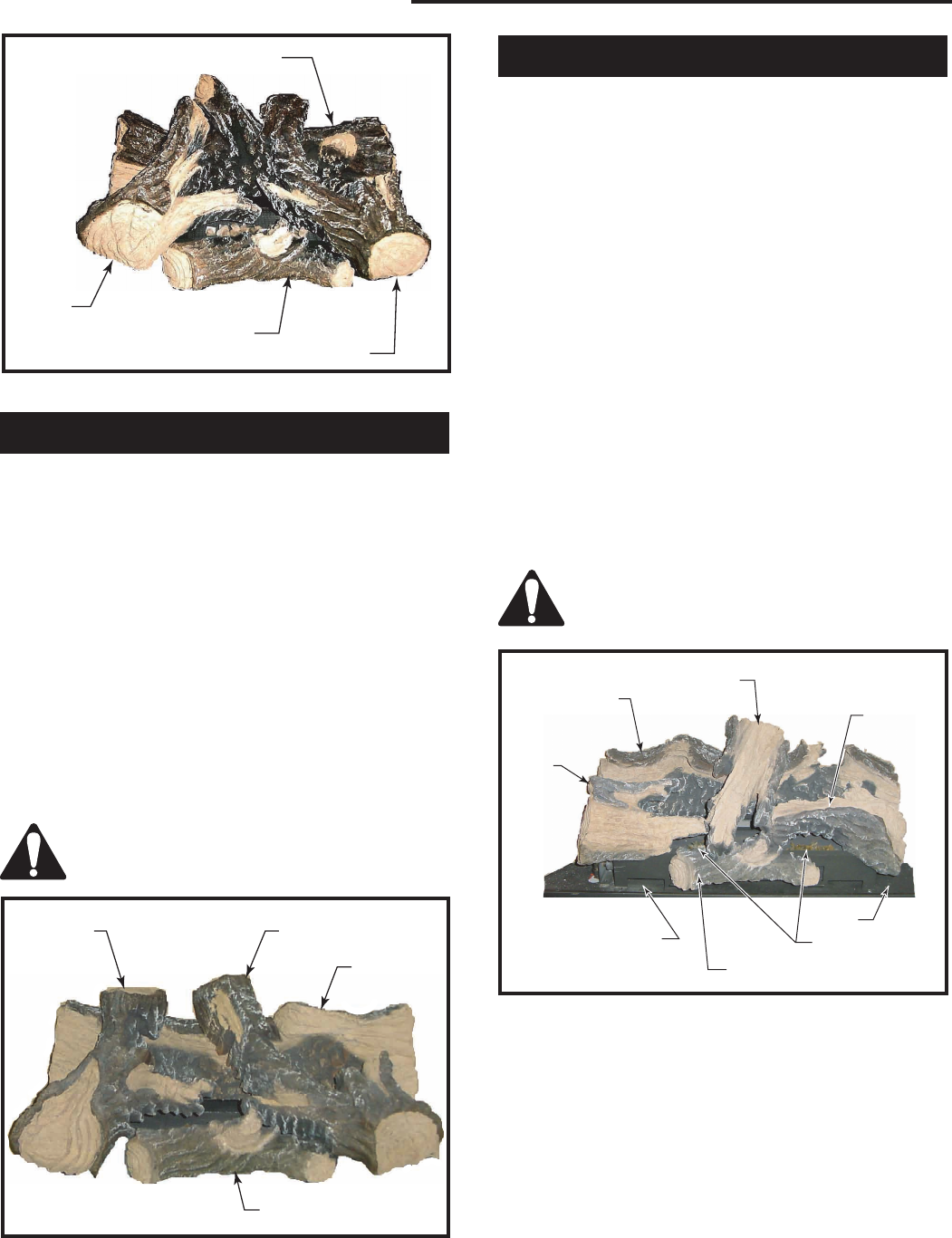
LG383
36LDVR logs
1/05
Rear
(B135)
Front Left
(B136) Front Center
(B138) Front Right
(B137)
LG383
Fig. 42 Correct log placement for 36LDVR.
39LDVR
1. Place rear lob (BC14) on rear bracket (ensure log is
centered and seated properly to the log support).
2. Place front left log (BC15). Use logʼs bottom hole to
locate it onto the front support and just rest on top of
the rear log.
3. Place front right log (BC16). Use logʼs bottom hole
to locate it onto the front support and the top hole to
the knob on the rear log.
4. Place front center log (B138) on top of the two small
shelves at the front log support, and between the left
and right logs.
5. Place ember material on top of burner. Scatter the
ember material over the tiles on the front area of
the burner housing. (Fig. 50) Separate it when un-
packed and keep it in a fluffy and loose condition for
a more realistic ember effect.
Do not place any of the lava rock material
on the burner housing assembly.
Front Left
(BC15) Front Right
(BC16)
Rear
(BC14)
Front Center
(B138) LG414
Fig. 43 Correct log placement for 39LDVR.
43LDVR
1. Place rear log (BD15) on rear bracket (ensure log is
centered and seated properly to the log support).
2. Place front left log (BD16). Use logʼs bottom notch to
locate it onto the front support and just rest on top of
the burner housing tile.
3. Place front right log (BD17). Use logʼs bottom notch
to locate it onto the front support and just rest on top
of the burner housing.
4. Place ember material on top of burner.
5. Scatter the ember material over the tiles on the front
area of the burner housing. (Fig. 44) Do not pack
the ember material. Separate it when unpacked and
keep it in a fluffy and loose condition for a more
realistic ember effect.
6. Place front center log (B138) on top of the two small
shelves at the front log support, and between the left
and right logs.
7. Place top center log (BD18) on top of the rear log
using the hole locator under the log and on top of
front right log.
8. Scatter lava rock material round the firebox base.
Do not place any of the lava rock material
on the burner housing assembly.
Rear
(BD15)
Top Center
(BBD18)
Front Right
(BD17)
Front
Left
(BD16)
Lava Rock
Front Center
(B138)
Ember Material
Lava
Rock
LG434
Fig. 44 Correct log placement for 43LDVR.
25
LDVR Series Direct Vent Gas Fireplace
10007317
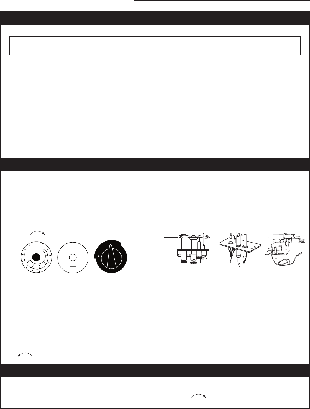
RN/RP & EN/EP Models
For units equipped with “HI/LO” valves the flame
adjustment is accomplished by rotating the “HI/LO”
adjustment knob located near the center of the gas
control valve. (Figs. 45 & 46)
It is important to periodically perform a visual check
of the pilot and burner flames. Compare them to the
illustrations. (Figs. 47-51)
If the flame patterns appear abnormal contact a
qualified service provider for service and adjustment.
Flame Characteristics
Flame & Temperature Adjustment
Turn
counterclockwise
to decrease
flame height
Turn clockwise
to increase
flame height
HV102
Honeywell hi/lo knob
4/5/99 djt
Fig. 45 Flame adjustment knob for Honeywell valve.
Honeywell Valve
L
O
H
I
FP390
FLAME ADJUSTMENT KNOB
11/21/96
Turn
counterclockwise
to increase
flame height
Turn clockwise
to decrease
flame height
SIT 820 Valve
Fig. 46 Flame adjustment knob for SIT valve.
SIT RN/RP
SIT EN/EP
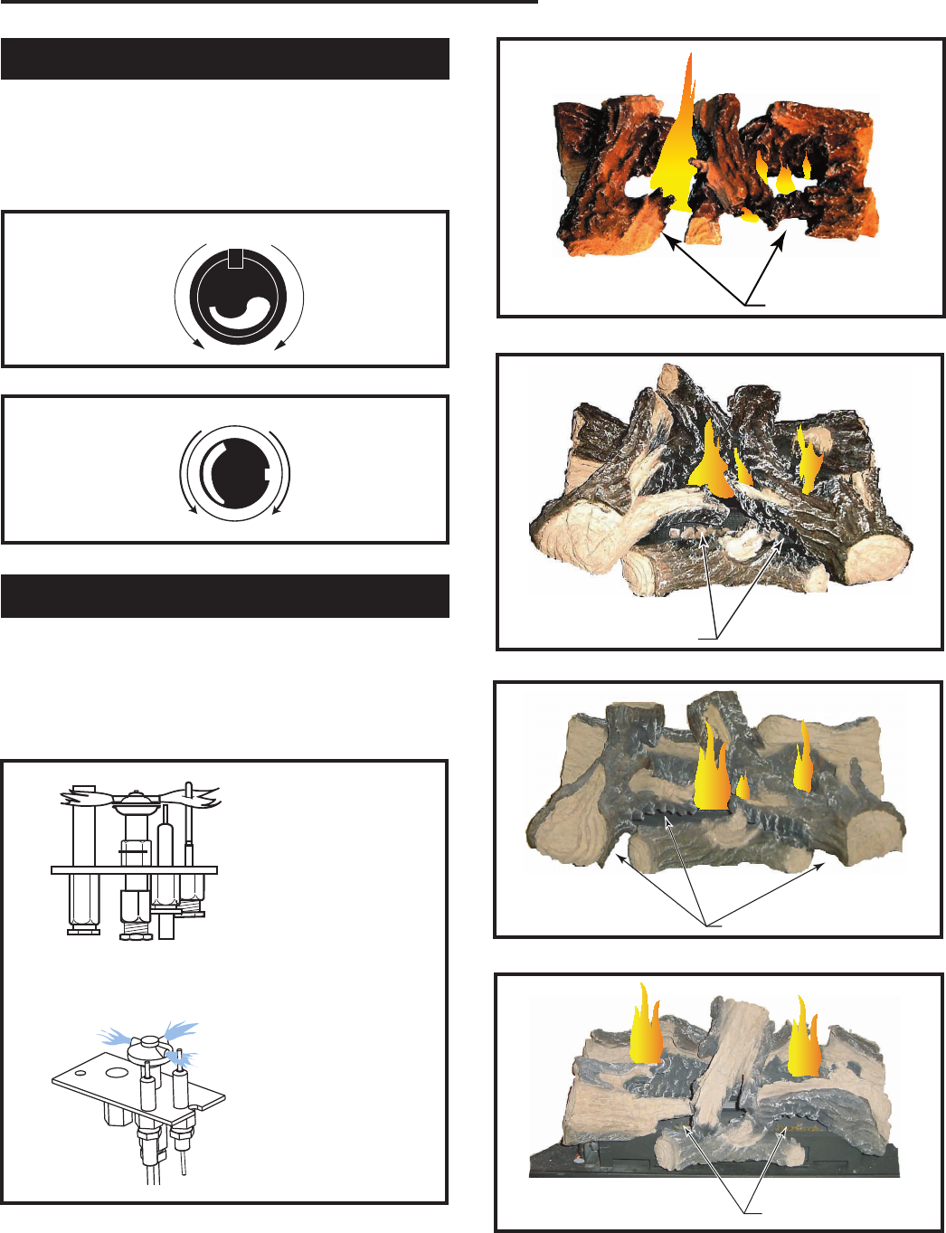
FP1541
Fig. 47 Correct pilot flame appearance.
LG384
33LDV log flames
1/05
Glowing Embers
LG384
Fig. 48 Correct burner flame appearance for 33LDVR.
LG385
36LDV log flames
1/05
Glowing Embers LG385
Fig. 49 Correct burner flame appearance for 36LDVR.
Glowing Embers
LG415
Fig. 50 Correct burner flame appearance for 39LDVR.
Glowing Embers
LG435
Fig. 51 Correct burner flame appearance for 43LDVR.
26
LDVR Series Direct Vent Gas Fireplace
10007317
3. Open control access panel.
4. Push in gas control knob slightly and turn clock-
wise to “OFF”. Do not force.
5. Close control access panel.
1. STOP! Read the safety information above.
2. Turn off all electrical power to the fireplace.
3. For MN/MP/TN/TP appliances ONLY, go on to
Step 4. For RN/RP appliances turn the ON/OFF
switch to “OFF” position or set thermostat to
lowest level.
4. Open control access panel.
5. Push in gas control knob slightly and turn clock-
wise to “OFF”.
10. Push the control knob all the way in and hold.
Immediately light the pilot by repeatedly depress-
ing the piezo spark ignitor until a flame appears.
Continue to hold the control knob in for about one
(1) minute after the pilot is lit. Release knob and it
will pop back up. Pilot should remain lit. If it goes
out, repeat steps 5 through 8.
FOR YOUR SAFETY READ BEFORE LIGHTING
Follow the gas supplierʼs instructions.
• If you cannot reach your gas supplier, call
the Fire Department
C. Use only your hand to push in or turn the gas
control knob. Never use tools. If the knob will not
push in or turn by hand, do not try to repair it, call a
qualified service technician. Applying force or any
attempted repair may result in a fire or explosion.
D. Do not use this fireplace if any part has been under
water. Immediately call a qualified service techni-
cian to inspect the heater and to replace any part of
the control system and any gas control which has
been under water.
A. This heater has a pilot which must be lit manu-
ally. When lighting the pilot follow these instruc-
tions exactly.
B. BEFORE LIGHTING smell all around the
heater area for gas. Be sure to smell next to
the floor because some gas is heavier than air
and will settle on the floor.
WHAT TO DO IF YOU SMELL GAS
• Do not try to light any fireplace
• Do not touch any electric switch
• Do not use any phone in your building
• Immediately call your gas supplier from a
neighborʼs phone.
To Turn Off Gas To Heater
Lighting and Operating Instructions
1. Turn the ON/OFF switch to Off position or set
the thermostat to lowest setting.
2. Turn off all electric power to the fireplace if
service is to be performed.
Lighting Instructions
6. Wait five (5) minutes to clear out any gas. Then
smell for gas, including near the floor. If you
smell gas, STOP! Follow “B” in the safety infor-
mation above. If you do not smell gas, go to the
next step.
7. Remove glass door before lighting pilot. (See
Glass Frame Removal section).
8. Visibly locate pilot by the main burner.
9. Turn knob on gas control counterclockwise
to “PILOT”.
• If knob does not pop up when released, stop
and immediately call your service technician or
gas supplier.
• If after several tries, the pilot will not stay lit,
turn the gas control knob to “OFF” and call your
service technician or gas supplier.
11. Replace glass door.
12. Turn gas control knob to “ON” position.
13. For RN/RP appliances turn the ON/OFF switch to
“ON” position or set thermostat to desired setting.
14. Turn on all electrical power to the fireplace.
WARNING:If you do not follow these instructions exactly, a fire or explosion
may result causing property damage, personal injury or loss of life.
Euro SIT SIT NOVA Honeywell
P
I
L
O
T
O
F
F
O
F
F
FP1067
lighting instruction
knobs
3/9/01 djt
5
4
3
2
1
O
F
F
P
i
l
o
t
3/8" - 1/2"
FP1068
Lighting instructions
Pilots
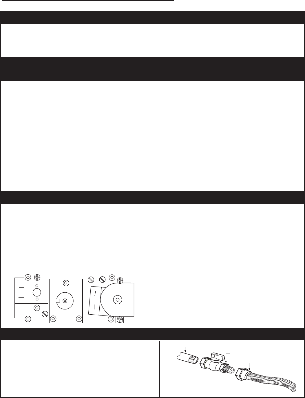
27
LDVR Series Direct Vent Gas Fireplace
10007317
Lighting and Operating Instructions
For Fireplaces equipped with SIT822 Gas Valve (EN or EP)
A. This fireplace is equipped with an ignition device
which automatically lights the pilot. DO NOT try to
light the pilot by hand.
B. BEFORE OPERATING, smell all around the
appliance area for gas. Be sure to smell next to
the floor because some gas is heavier than the air
and will settle on the floor.
What to do if you smell gas
• Do not try to light any appliance
• Do not operate any electrical switch.
• Do not use any phone in your building.
• Immediately call your gas supplier from a
neighborʼs phone.
FOR YOUR SAFETY READ THE FOLLOWING WARNINGS
BEFORE LIGHTING THE APPLIANCE
1. STOP! Read the safety information above before
continuing.
2. Turn off all electrical power to the appliance.
3. This appliance is equipped with an ignition device
which automatically lights the pilot. DO NOT try to
light the pilot by hand.
4. Access the gas control by lowering the lower
access door (louvre assembly).
Follow the gas suppliers instructions.
• If you cannot contact your gas supplier call
the Fire Department
C. Use only your hand to push in or turn the gas control
knob. Never use tools. If the knob will not push in
or turn by hand do not try to repair it, call a qualified
service technician. Force or attempting repair may
result in a fire or explosion.
D. Do not use this appliance if any part has been under
water. Immediately call a qualified service technician
to inspect the appliance and replace any part of the
control system and any gas control that has been
under water.
5. Turn the remote switch, if used, OFF. Turn the
wireless remote, if used, OFF.
6. Wait five (5) minutes to clear out any gas. Then
smell for gas, including near the floor. If you smell
gas STOP. Follow instructions B in the safety
warnings above. If you do not smell gas go onto the
next step.
7. Close the access door.
8. Turn ON all electrical power to the appliance.
9. Turn remote switch or wireless remote to “ON”.
10. If the appliance will not operate, follow the
instructions TURNING OFF THE GAS TO THE
APPLIANCE and call your service technician or
gas supplier.
1. Turn the remote switch to the “OFF” position.
2. Turn OFF all electrical power to the fireplace if
service is required.
3 Open the lower access panel.
4. Turn the shut-off valve on the flexible gas line to
the “OFF” position.
Warning:If you do not follow these instructions exactly, a fire or explosion
may result causing property damage, personal injury and loss of life.
Lighting Instructions
Turning Off the Gas to the Appliance
HI
LO
FP297A
FP297A
INSTA VENT FREE
UVHB26 GAS SUPPLY
7/1/98
Valve in the on position
1/2” Gas Supply
1/2” NPT x 1/2” Flare Shut-Off
Valve 3/8” Flex Line
(From Valve)
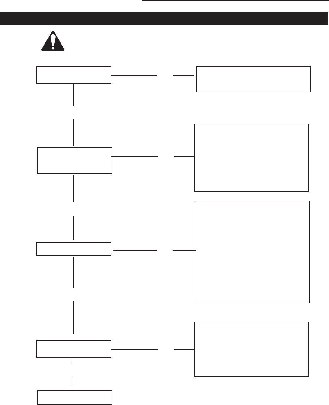
28
LDVR Series Direct Vent Gas Fireplace
10007317
Troubleshooting - Honeywell Millivolt Valve
Remove Window Frame Assembly Before Service Work
START CHECK
Gas Supply On
▼
▼
▼
▼▼
Pilot Lights With Piezo
Ignitor
• Lockout Has Engaged. Wait 60
Seconds And Try Again.
• For Spark At Electrode While
Depressing Piezo
1/8" Gap To Pilot Hood Needed.
• All Wiring Connections
• Replace Piezo Ignitor
• Supply Line Hooked Up
• Shutoff Valve Open
Pilot Stays Lit
• For Air In The Lines
• Thermopile Needs A Min.
325mv. Adjust Pilot Flame
Height.
• All Wiring Connections
• Replace Thermopile
• Thermocouple Needs A Min. Of
14mv
• Defective Valve. Turn To Pilot,
Meter Should Read Greater
Than 100mv. If Not, Replace.
Pilot Lights Main Burner
• Valve Is Turned On
• Wall Switch Is Not Turned On.
Watch For Grounded Wires!
• Thermopile Needs A Min. 325mv.
• Plugged Burner Orifice
SYSTEM OK
▼
YES
NO
NO
▼
NO
▼
NO
YES
YES
YES
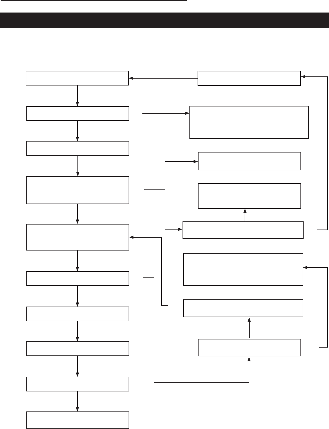
29
LDVR Series Direct Vent Gas Fireplace
10007317
Troubleshooting the Gas Control System
SIT 822 Valve with Synetek Electronic Control
Operating Diagram
Normal Operation
ON/OFF Switch Closed?
Safe Start Check On?
0 Sec Purge
Pilot Flame Sense OK?
ON/OFF Switch Opened?
Pilot and Main Valve OFF?
0 sec Post Purge?
Ignition Trial: 30 sec Spark ON
Pilot Valve ON. Has Flame
been Detected within 30 sec?
Spark Off. Main Valve ON.
Pilot Flame Continuously
Monitored
Heating Cycle Complete LED:
OFF
NO
YES
NO
NO
YES
Abnormal Operation
5 sec Inter-Trial Delay
LED: Steady Flash?
Lockout: Flame detected out of sequence
Reset by interrupting ON/OFF switch or
power for 10 sec
LED: 5 Flashes?
Reverse power cord polarity
LED: 2 Flashes?
Reset by interrupting ON/OFF
switch for power for 10 sec
Pilot, Valve OFF, Spark OFF
Have three ignition trials been completed?
LED: 3 Flashes?
Lockout: Flame Loss
Reset by interrupting ON/OFF switch or
power for 10 sec
Main Valve OFF, Spark ON
Has flame been detected within 30 sec?
Have three pilot flame losses been
detected?
NO
YES
NO
YES
YES
YES
YES
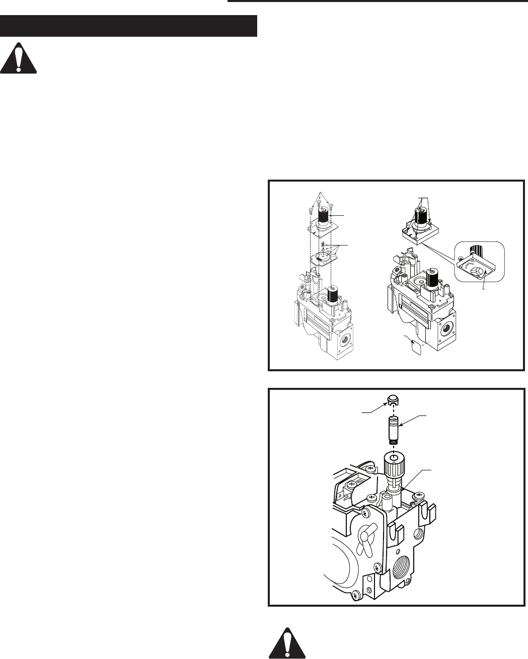
30
LDVR Series Direct Vent Gas Fireplace
10007317
The conversion of this appliance from one
gas to another must be carried out by an
authorized service provider.
1. Disconnect power to the unit and shut off the gas sup-
ply.
2. Remove window frame assembly.
3. Carefully remove the logs & lava rock material.
4. Remove the screws that are holding the burner hous-
ing in place.
5. Remove the burner housing assembly. Depending on
the model of the appliance you may have to loosen
the pilot bracket retaining screw/nut to allow the pilot
and bracket assembly to tilt and give enough clear-
ance to remove the burner housing assembly.
6. Remove the main burner orifice and replace it with the
orifice supplied in the conversion kit.
7. SIT top Convertible Pilot
Gently lift off the pilot hood from the pilot. (Do not re-
move the spring clip holding the hood in place). Using
a 5/32” Allen key, unscrew the exposed orifice. Insert
the new orifice supplied in the kit, do not over tighten
the orifice. Replace the pilot hood ensuring the index
tab aligns with the notch on the hood.
8. PSE Pilot
Using a suitable wrench on the hexagonal body un-
screw the pilot hood assembly from the pilot, do
not twist the hood itself. Remove the orifice and
replace it with the new orifice supplied in the kit. Refit
the pilot hood assembly. Do not over-tighten the pilot
hood. The hood must return to its original alignment.
Take care not to damage the thermocouple, thermo-
pile or igniter.
9. SIT 820 NOVA Gas Control Valve (Fig. 52)
a. Using a Torx T20 or slotted screwdriver, remove
and save the three pressure regulator mounting
screws (A), pressure regulator tower (B) and
diaphram (C).
b. Ensure the rubber gasket (D) is properly positioned
and install the new HI/LO pressure regulator to the
valve using the new screws (E) supplied with the
kit. Tighten screws securely. (Reference torque - 25
in.LB)
c. Install the enclosed identification label (F) to the
valve body where it can be easily seen.
Honeywell Gas Control Valve (Fig. 53)
The Honeywell valve fitted to this unit is suitable for
use with LP or Natural Gas. It is converted to the
required gas application by the installation of a color
coded “conversion screw”.
a. Using a suitable small screwdriver lift out the
central regulator cap from the “HI/LO” knob on the
valve.
b. Unscrew the exposed conversion screw.
c. Insert the new color coded conversion screw. Do
not over-tighten the screw, it must be finger tight.
Fuel Conversion Instructions d. Refit the regulator cap.
e. Mount conversion label supplied with conversion
screw to valve in a visible position.
10. Reassemble the fireplace in the reverse order, except
for the window frame assembly. Leave this off until
after the unit has been checked for leaks and the gas
supply has been bled.
11. After bleeding the gas line and checking for leaks with
a soap solution, replace the window frame assembly.
Fire up the unit, check for flame impingement on the
logs, adjusting them if necessary. Check the manifold
and supply pressures against the appliance specifica-
tions.
The procedure for converting from one gas to
another is the same regardless of the initial
gas used. The only variation is in the orifice
sizes and component part numbers. Your
authorized service provider will ensure the
correct parts are used.
L
O
HV120
Honeywell valve
conversion
9/24/02 djt
Regulator Cap Conversion Screw
Pressure Regulator
Housing
HV120
Fig. 53 Honeywell Gas Valve.
Fig. 52 Nova SIT820 Gas Valve.
D
E
F
FC108
SIT
regulator
conversion
10/03
O
F
F
P
I
L
O
T
O
FC107
SIT820
valve conversion
10/03
A
B
C
O
F
F
P
I
L
O
T
O
FC107/108

31
LDVR Series Direct Vent Gas Fireplace
10007317
Burner and Burner Compartment
It is important to keep the burner and the burner
compartment clean. At least once per year the logs and
lava rock/ember material should be removed and the
burner compartment vacuumed and wiped out. Remove
and refit the logs as per the instructions in this manual.
Always handle the logs with care as they
are fragile and may also be hot if the
fireplace has been in use.
FK24/FK12 Fan Assembly
The fan unit requires periodic cleaning. At least once
per month in the operating season open the lower
louvre panels and wipe or vacuum the area around the
fan to remove any build up of dust or lint.
Brass Trim
Clean the brass trim pieces using a soft cloth lightly
dampened with lemon oil. Do not use water or
household cleaners on any brass components.
Cleaning the Standing
Pilot Control System
The burner and control system consist of:
• burner • gas orifice
• pilot assembly • thermopile
• millivolt gas valve
Most of these components may require only an
occasional checkup and cleaning and some may
require adjustment. If repair is necessary, it should
be performed by a qualified technician.
1. Turn off pilot light at gas valve.
2. Allow fireplace to cool if it has been operating.
3. Remove window frame assembly. (Refer to Window
Frame Assembly Removal section.)
4. Remove logs.
5. Vacuum burner compartment especially around
orifice primary air openings.
6. Visually inspect pilot. Brush or blow away any dust
or lint accumulation.
7. Reinstall logs.
8. Ignite pilot - Refer to Lighting Instructions.
9. Reinstall window frame assembly.
To obtain proper operation, it is imperative that the pilot
and burnerʼs flame characteristics are steady, not lifting
or floating.
Typically, the top 3/8” to 1/2” of the thermopile should
be engulfed in the pilot flame. (Refer to Page 25, Figure
47)
To adjust pilot burner: (by qualified service technician)
1. Remove pilot adjustment cap
2. Adjust pilot screw to provide properly sized flame.
3. Replace pilot adjustment cap.
The primary air shutter is set at factory and should
only be adjusted, if necessary, by a qualified service
technician.
Maintenance
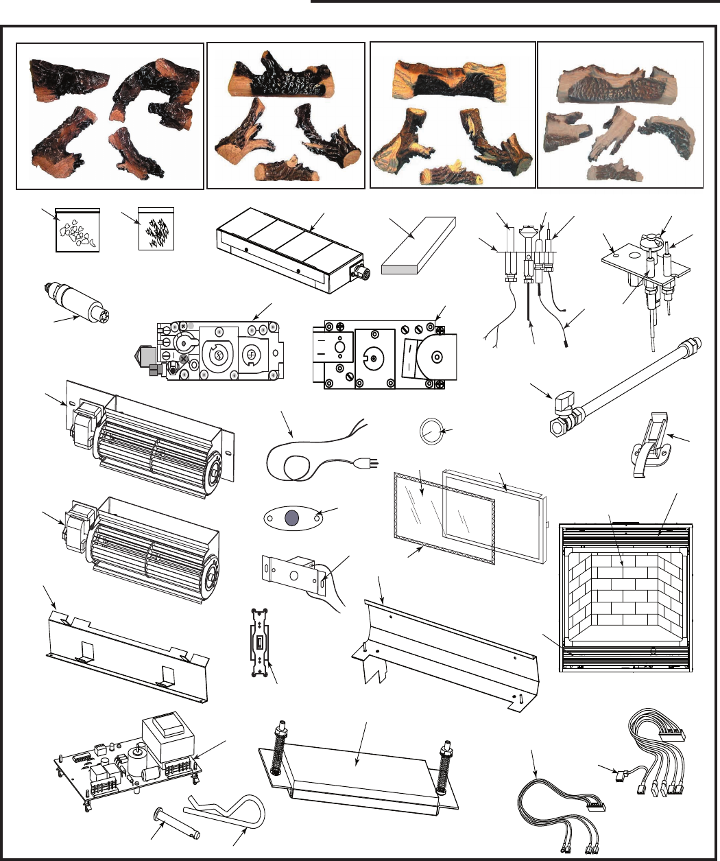
32
LDVR Series Direct Vent Gas Fireplace
10007317
CFM Specialty Home Products reserves the right to make changes in design, materials, specifications, prices and discontinue colors and products
at any time, without notice.
33/36/39/43LDVR
HI
LO
22
21
19a,b
18a,b
41
17
30
33LDVR
1
1a
1b
1c
1d
1e
1f
1a
36LDVR
1
1g
1h 1i 23
6a,b
8
7a,b
9
11
12
13
14
15
16
20
23
24
25
26
27 29
28
31
32
33
34
35
36
37
39
7317
LDVR parts
1/05
40
139LDVR
1a 1b
1c
1d
43LDVR
1b
1c
1a
1d
1g
42 43

33
LDVR Series Direct Vent Gas Fireplace
10007317
LDVR (continued)
Ref. Description 33LDVR 36LDVR 39LDVR 43LDVR
1. Log Set (complete) 10007567 10007318 10008214 10008314
1a. Log Front Left A43 B136 BC15 BD16
1b. Log Front Right -- B137 BC16 BD17
1c. Log Front Center -- B138 B138 B138
1d. Log Rear -- B135 BC14 BD15
1e. Log Rear Left A41 -- -- --
1f. Log Rear Right A42 -- -- --
1g. Log Top Center A44 -- -- BD18
1h. Lava Rock Package 10001454 10001454 10001454 10001454
1i. Ember (Package) 51915 51915 51915 51915
2a. Burner Housing Assy - Natural 10007558 10007127 10008218 10008464
2b. Burner Housing Assy - LP 10007558 10008042 10008586 10008587
3. Ceramic Tile (Single) 57803 57803 57803 57803
4a. Orifice Burner - Natural Refer to Rating Plate for Orifice Size
4b. Orifice Burner - Propane Refer to Rating Plate for Orifice Size
5a. Orifice Pilot - Natural 10002268 10002268 10002268 10002268
5b. Orifice Pilot - Propane 10002269 10002269 10002269 10002269
6a. Pilot Assy SIT - RN 10002264 10002264 10002264 10002264
6b. PIlot Assy SIT - RP 10002265 10002265 10002265 10002265
7a. PIlot Assy SIT - EN 10002387 10002387 10002387 10002387
7b. Pilot Assy SIT - EP 10002388 10002388 10002388 10002388
8. Pilot Tubing w/Fittings SIT 10001296 10001296 10001296 10001296
9. Pilot Hood 10002385 10002385 10002385 10002385
10. Manifold Tubing w/Fittings 57318 57318 57318 57318
11. Thermocouple - RN/RP 53373 53373 53373 53373
12. Thermopile - RN/RP 51827 51827 51827 51827
13. Electrode Ignitor w/Cable - RN/RP 10001297 10001297 10001297 10001297
14. Electrode Ignitor - EN/EP 52465 52465 52465 52465
15. Cable Ignitor - EN/EP 10000696 10000696 10000696 10000696
16. Sensing Electrode - EN/EP 57885 57885 57885 57885
17. Ignitor Piezo SIT820 Valve 52464 52464 52464 52464
18a. Valve SIT 820 - RN 52677 52677 52677 52677
18b. Valve SIT 820 - RP 52678 52678 52678 52678
19a. Valve SIT 822 - EN 57884 57884 57884 57884
19b. Valve SIT 822 - EP 57883 57883 57883 57883
20. Flexible Gas Line w/ON/OFF Shut-Off Valve 20002500 20002500 20002500 20002500
21. Fan Assy w/Bracket (FK24 Option) ZA1100 ZA1100 ZA1100 ZA1100
22. Fan Assy (FK12 Option) ZA1110 ZA1110 ZA1110 ZA1110
23. Electrical Cord (6ft) 51865 51865 51865 51865
24. Fan Temperature Sensor (FK24) 51704 51704 51704 51704
25. Speed Control (FK24) 51738 51738 51738 51738
26. Speed Control Knob (FK24) 51882 51882 51882 51882
27. Glass w/Gasket 10007391 10007094 10008212 10008310
28. Gasket Glass 57317 57317 57317 37317
29. Frame Window 10007399 10007093 10007972 10008309
30. Clamp Frame Window 54174 54174 54174 54174
31. Top Louvre Assy 10007400 10007090 10007984 10008311
32. Bottom Louvre Assy 10007397 10007092 10007986 10008307
33a. Support Rear Log 10007561 10007162 10008211 10008480
33b. Support Rear Log - LP 10007561 10008045 10008211 10008480
34. Support Front Log 10007562 10007112 10008416 10008469
35. ON/OFF Switch 51842 51842 51842 51842
36. Ceramic Refractory Lining Kit (Optional) GADT3I0 GADT3J0 GADT3K0 GADT3N0

34
LDVR Series Direct Vent Gas Fireplace
10007317
LDVR (continued)
Ref. Description 33LDVR 36LDVR 39LDVR 43LDVR
37. Relief Plate Assy (Burner Base) 10004192 10004192 10004192 10004192
38. Remote Switch Kit (Not shown) 53875 53875 53875 53875
39. Ignition Control from Synetek (EN) 10007939 10007939 10007939 10007939
40. Wire Harness (EN) Synetek (low voltage) 10008139 10008139 10008139 10008139
41. Wire Harness (EN) Synetek (high voltage) 10008140 10008140 10008140 10008140
42. Clevis Pin 10008615 10008615 10008615 10008615
43. Clip Pin Hitch 10008616 10008616 10008616 10008616
Fuel Conversion Kits
Conversion Kit, NG to LP
33LDVR Kit # 10008233
36LDVR Kit # 10008235
39LDVR Kit # 10008237
43LDVR Kit # 10008239
Conversion Kit, LP to NG
33LDVR Kit # 10008234
36LDVR Kit # 10008236
39LDVR Kit # 10008238
43LDVR Kit # 10008240
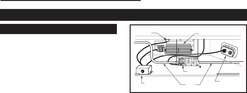
35
LDVR Series Direct Vent Gas Fireplace
10007317
FK24 Fan Assembly
This auxiliary fan system increases the efficiency of the
circulation of the heated air.
The FK24 fan kit allows variable speed control of the
circulation fan and also incorporates a heat sensor in
the circuit.
Specifications
115 Volt / 60Hz / 56 Watts
Maintenance
The fan itself does not require regular maintenance,
however periodic cleaning of the fan and the
surrounding area is required.
Check the area under the control door (lower louvre
assembly) and in front of the fan and wipe or vacuum
this area at least once a month during the operating
season.
Installation
The fan assembly and other components are supplied
fully wired, eliminating the need for a licensed
electrician to carry out the installation.
If hard wiring the fan using Method B (following) we
strongly recommend the use of a licensed electrician.
1. Open the lower louvre assembly. Move the fan &
bracket assembly around the gas valve and lines to
locate the unit onto the screw studs on the back of
the fireplace.
2. Install the thermal sensor under the bottom of the of
the firebox, locating it over the two 10mm studs and
secure it with nuts.
3. Locate the fan speed control unit. This can be fitted
behind the lower louvre assembly as in Figure 54
or located remotely in a conveniently located wall
mounted electrical box. Remote location of the
speed control will require suitable extension of the
component wiring.
4. The power supply may be connected in two ways:
Method A
Route the 6ʼ lead fitted to the unit to a conveniently
located wall socket.
Method B (Using EB-1 Receptacle Box)
The EB-1 receptacle box (Pt. # ZA1200) may be
hard wired into the house supply. The fan lead is
then plugged into the EB-1 box.
For instruction
on wiring the EB-1 receptacle box see the earlier
chapter in the Installation section of this manual.
FK12
This auxiliary fan system increases the efficiency of the
circulation of the heating air.
The FK12 Fan Assembly is a fixed speed fan system
and does not allow for variable speed control. It does
not use the speed control unit or the heat sensor used
in the FK24 Kit.
Specifications
115 Volts / 60 Hz / 56 Watts.
Maintenance
The fan itself does not require regular maintenance,
however periodic cleaning of the fan and the
surrounding area is required.
Check the area under the control door (lower louvre
assembly) and in front of the fan and wipe or vacuum
this area at least once a month during the operating
season.
Installation
The fan assembly is supplied fully wired eliminating
the need for a licensed electrician to carry out the
installation.
1. Open the lower Louvre assembly. Move the fan &
bracket assembly around the gas valve and lines to
locate the unit against the back wall of the
appliance, resting on the base.
2. With the protective cover removed from the self-
adhesive ʻVelcroʼ strips apply mild pressure to the
fan & bracket unit to secure the strips to the metal
panels. No further securing is required.
3. Power to the fan can be supplied by plugging the
supplied lead into a conveniently located wall socket
or by using a hard-wired EB-1 receptacle box.
Optional Accessories Available
Fan Kits
FP1230
FK24
fan install
11/02
Thermal
Sensor Fan
Fan Speed
Switch Gas
Lines
Valve
EB-1 Recep-
tacle Box
FP1230
Fig. 54 FK24 fan placement.
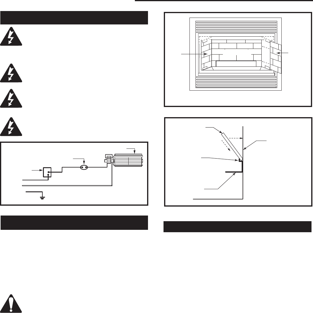
36
LDVR Series Direct Vent Gas Fireplace
10007317
Ceramic refractory panels are available in kit form for
the LDV series appliances
Appliance Model Kit Name
33LDVR 33LDVRCR
36LDVR 36LDVCR
39LDVR 39LDVCR
43LDVR 43LDVCR
Ceramic Refractory Kits
The fireplace, when installed, must be
electrically connected and grounded in
accordance with local codes or, in the
absence of local codes, with the current
CSA C22.1 Canadian Electric Code.
For USA installations follow the local codes
and the national electrical code ANSI/NFPA
No. 70.
Should this fan require servicing or repair
the power supply must be disconnected.
For rewiring of any replacement parts refer
to Figure 55.
Any electrical rewiring of this fan must be
done by a licensed electrician.
Wiring Instructions
Black
White
Ground
FP394
WIRING DIAGRAM
11/20/96
Speed
Control
Temperature Sen-
sor
Fan
FP1025
Fig. 55 FK24 fan wiring.
Take care when handling the refractory
panels as they are fragile until held in place
and supported.
Installation Refer to Figures 56 & 57
1. Remove the front window frame assembly.
2. Remove the logs.
3. Place the rear refractory panel in place. Locate the
lower edge of the panel in the ledge formed by the
top of the rear log support bracket.
4. Slide the side refractory panels into place to hold
the rear panel secure. Repeat the procedure on the
other side.
5. Replace the logs and window frame assembly.
For aesthetic purposes we recommend aligning the
horizontal mortar lines.
FP1231
Ceramic panels
11/02
Side
Panel Side
Panel
Log Support
Burner Tray
Back Panel
FP1231
Fig. 56 Ceramic panel installation.
FP1232
rear ceramic panel
11/02
Rear Refrac-
tory Panel
Firebox Back
Panel
Rear Panel
Support
Brackets
Rear Log
Support
FP1232
Fig. 57 Rear refractory panel installation.
Remote Controls
Optional remote control units are available to control
different functions of the appliances
Model Function/s Controlled
MRCI ON/OFF
MRC2 ON/OFF and Temperature
MRC3 ON/OFF and Temperature
control with a digital display
and programmable 24 hour clock
IMT Wall mounted thermostat control
(must be used in bedroom installations)

37
LDVR Series Direct Vent Gas Fireplace
10007317
Optional Trim Kits
Louvre Accent Trim
Appliance Model Main Louvre Kit Additional Louvre
Polished Brass
33LDVR 33DVLMP 33DVLAP
36LDVR 36DVLMP 36DVLAP
39LDVR 39DVLMP 39DVLAP
43LDVR 43DVLMP 43DVLAP
Antique Brass
33LDVR 33DVLMA 33DVLAA
36LDVR 36DVLMA 36DVLAA
39LDVR 39DVLMA 39DVLAA
43LDVR 43DVLMA 43DVLAA
Rustic Bronze
33LDVR 33DVLMR 33DVLAR
36LDVR 36DVLMR 36DVLAR
39LDVR 39DVLMR 39DVLAR
43LDVR 43DVLMR 43DVLAR
Pewter
33LDVR 33DVLMS 33DVLAS
36LDVR 36DVLMS 36DVLAS
39LDVR 39DVLMS 39DVLAS
43LDVR 43DVLMS 43DVLAS
Regular Trim Kit
Appliance Model Trim Kit
33LDVR 33DVRTKP Polished Brass
33LDVR 33DVRTKA Antique Brass
33LDVR 33DVRRKS Pewter
33LDVR 33DVRTKR Rustic Bronze
Adjustable Regular Trim Kit
Appliance Model Trim Kit
36LDVR ADVRTKP Polished Brass
36LDVR ADVRTKA Antique Brass
36LDVR ADVRRKS Pewter
36LDVR ADVRTKR Rustic Bronze
39LDVR ADVRTKP Polished Brass
39LDVR ADVRTKA Antique Brass
39LDVR ADVRRKS Pewter
39LDVR ADVRTKR Rustic Bronze
Medium Trim Kit
Appliance Model Trim Kit
33LDVR 33DVMTKP Polished Brass
33LDVR 33DVMTKA Antique Brass
33LDVR 33DVMTKS Pewter
33LDVR 33DVMTKB Black
43LDVR 43DVMTKP Polished Brass
43LDVR 43DVMTKA Antique Brass
43LDVR 43DVMTKS Pewter
43LDVR 43DVMTKB Black
Adjustable Medium Trim Kit
Appliance Model Trim Kit
36LDVR ADVMTKP Polished Brass
36LDVR ADVMTKA Antique Brass
36LDVR ADVMTKS Pewter
36LDVR ADVMTKB Black
39LDVR ADVMTKP Polished Brass
39LDVR ADVMTKA Antique Brass
39LDVR ADVMTKS Pewter
39LDVR ADVMTKB Black
Screen Door Kit
Appliance Model Kit Model
33LDVR 33DVSDKG Gold
36LDVR 36DVSDKG Gold
39LDVR 39DVSDKG Gold
33LDVR 33DVSDKS Pewter
36LDVR 36DVSDKS Pewter
39LDVR 39DVSDKS Pewter
33LDVR 33DVSDKB Black
36LDVR 36DVSDKB Black
39LDVR 39DVSDKB Black
33LDVR 33DVSDKR Rustic Bronze
36LDVR 36DVSDKR Rustic Bronze
39LDVR 39DVSDKR Rustic Bronze
Filigree Louvre Kit
Appliance Model Kit Model
33LDVR 33DVFKB Black
36LDVR 36DVFKB Black
39LDVR 39DVFKB Black
33LDVR 33DVFKS Pewter
36LDVR 36DVFKS Pewter
39LDVR 39DVFKS Pewter
33LDVR 33DVFKG Gold
36LDVR 36DVFKG Gold
39LDVR 39DVFKG Gold
33LDVR 33DVFKR Rustic Bronze
36LDVR 36DVFKR Rustic Bronze
39LDVR 39DVFKR Rustic Bronze

38
LDVR Series Direct Vent Gas Fireplace
10007317

39
LDVR Series Direct Vent Gas Fireplace
10007317
BASIC WARRANTY
CFM Specialty Home Products (hereinafter referred to collectively as
the Company) warrants that your new Vermont Castings or Majestic
Gas Fireplace/Stove is free from manufacturing and material defects
for a period of one year from the date of purchase, subject to the
following conditions and limitations.
EXTENDED LIFETIME WARRANTY
The heat exchanger, where applicable, and combustion chamber
of every Vermont Castings or Majestic gas product is warranted for
life against through wall perforation. All appliances equipped with an
Insta-Flame Ceramic Burner have limited lifetime coverage on the
ceramic burner plaque. Warrantees are made to the original owner
subject to proof of purchase and the conditions and limitations listed
on this Warranty Document
COMPONENT WARRANTY
CAST IRON: All external and internal cast iron parts are warranted for a
period of three years.
Note: On porcelain enamel finished external parts and accessories The
Company offers no Warranty on chipping of enamel surfaces. Inspect
all product prior to accepting it for any damage to the enamel.
The salt air environment of coastal areas or a high humidity environment
can be corrosive to the porcelain enamel finish. These conditions can
cause rusting of the cast iron beneath the porcelain enamel finish,
which will cause the finish to flake off.
Dye lot variations with replacement parts and/or accessories can occur
and are not covered by warranty.
GLASS DOORS: Glass doors are covered for a period of one year.
Glass doors are not warranted for breakage due to misuse or accident.
Glass doors are not covered for discoloration or burned in stains due to
environmental issues, or improper cleaning and maintenance.
BRASS PLATED PARTS AND ACCESSORIES: Brass parts should be
cleaned with Lemon oil only. Brass cleaners cannot be used. Mortar
mix and masonry cleaners may corrode the brass finish. The Company
will not be responsible for, nor will it warrant any brass parts which are
damaged by external chemicals or down draft conditions.
GAS VALVES: Gas valves are covered for a period of one year
ELECTRONIC AND MECHANICAL COMPONENTS: Electronic and
mechanical components of the burner assembly are covered for one year.
All steel tube burners are warranted for one year.
ACCESSORIES: Unless otherwise noted all components and CFM
Specialty Home Products company supplied accessories are covered for
a period of one year.
CONDITIONS AND LIMITATIONS
• This new Vermont Castings or Majestic product must be installed by
a competent, authorized, service contractor. A licensed technician, as
prescribed by the local jurisdiction must perform any installation/service
work. It must be installed and operated at all times in accordance with
the Installation and Operating instructions furnished with the product.
Any alteration, willful abuse, accident, or misuse of the product shall
nullify this warranty.
• This warranty is non-transferable, and is made to the original owner,
provided that the purchase was made through an authorized supplier
of the Company.
• The customer must pay for any Authorized Dealer in-home travel fees
or service charges for in-home repair work. It is the dealers option
whether the repair work will be done in the customerʼs home or in the
dealerʼs shop.
• If upon inspection, the damage is found to be the fault of the manufacturer,
repairs will be authorized at no charge to the customer parts and/or
labor.
• Any part and/or component replaced under the provisions of this
warranty is covered for six months or the remainder of the original
warranty, whichever is longest.
• This warranty is limited to the repair of or replacement of part(s) found
to be defective in material or workmanship, provided that such part(s)
have been subjected to normal conditions of use and service, after
said defect is confirmed by the Companyʼs inspection.
• The company may, at its discretion, fully discharge all obligations
with respect to this warranty by refunding the wholesale price of the
defective part(s)
• Any installation, labor, construction, transportation, or other related
costs/expenses arising from defective part(s), repair, replacement,
or otherwise of same, will not be covered by this warranty, nor shall
the Company assume responsibility for same. Further, the Company
will not be responsible for any incidental, indirect, or consequential
damages except as provided by law.
• SOME STATES DO NOT ALLOW FOR THE EXCLUSION OR
LIMITATIONS OF INCIDENTAL AND CONSEQUENTIAL DAMAGES
OR LIMITATIONS ON HOW LONG AN IMPLIED WARRANTY
LASTS, SO THE ABOVE LIMITATIONS MAY NOT APPLY TO YOUR
CIRCUMSTANCES. THIS WARRANTY GIVES YOU SPECIFIC
RIGHTS AND YOU MAY HAVE OTHER RIGHTS WHICH VARY FROM
STATE TO STATE.
• All other warranties-expressed or implied- with respect to the product,
its components and accessories, or any obligations/liabilities on the
part of the Company are hereby expressly excluded.
• The Company neither assumes, nor authorizes any third party to
assume on its behalf, any other liabilities with respect to the sale of
this Vermont Castings or Majestic product
• The warranties as outlined within this document do not apply to chimney
components or other non CFM Specialty Home Products accessories
used in conjunction with the installation of this product..
• Damage to the unit while in transit is not covered by this warranty but
is subject to claim against the common carrier. Contact the dealer
from whom you purchased your fireplace/stove (do not operate the
appliance as this might negate the ability to process the claim with the
carrier).
• The Company will not be responsible for:
a) Down drafts or spillage caused by environmental conditions such
as near-by trees, buildings, roof tops, hills, or mountains.
b) Inadequate ventilation or negative air pressure caused by
mechanical systems such as furnaces, fans, clothes dryers, etc.
• This warranty is void if:
a) The fireplace has been operated in atmospheres contaminated by
chlorine, fluorine, or other damaging chemicals.
b) The fireplace has been subjected to prolonged periods of dampness
or condensation
c) Any damages to the fireplace, combustion chamber, heat exchanger
or other components due to water, or weather damage, which is the
result of but not limited to, improper chimney/venting installation.
d) Any alteration, willful abuse, accident, or misuse of the product
has occurred.
IF WARRANTY SERVICE IS NEEDED…
1) Contact your supplier. Make sure you have your warranty,
your sales receipt, and the model/serial number of your CFM
Specialty Home Products product.
2) DO NOT ATTEMPT TO DO ANY SERVICE WORK
YOURSELF.
LIMITED LIFETIME WARRANTY
PRODUCT COVERED BY THIS WARRANTY
All Vermont Castings gas stoves, gas inserts, and gas fireplaces, and all Majestic or Northern Flame brand gas fireplaces
equipped with an Insta-Flame Ceramic Burner, or standard steel tube burner.
Efficiency Ratings
Model EnerGuide Ratings Steady State (%) D.O.E.
Fireplace Efficiency (%) Fan-OFF Fan-ON (AFUE%)
33LDVRRN 62.6 81 82 59
33LDVRRP 62.6 82 83 59
33LDVREN 72.7 81 82 59
33LDVREP 72.7 82 83 59
36LDVRRN 57.5 81 82 58
36LDVRRP 57.5 82 83 58
36LDVREN 63.6 81 82 58
36LDVREP 63.6 82 83 58
39LDVRRN 50.2 76 79 63
39LDVRRP 50.2 79 80 63
39LDVREN 54.2 78 79 63
39LDVREP 54.2 79 80 63
43LDVRRN 54.3 77 78 63
43LDVRRP 54.3 78 79 63
43LDVREN 58.3 77 78 63
43LDVREP 58.3 78 79 63
410 Admiral Blvd. • Mississauga, Ontario, Canada L5T 2N6 • 905-670-7777
www.majesticproducts.com • www.vermontcastings.com
CFM Specialty Home Products
