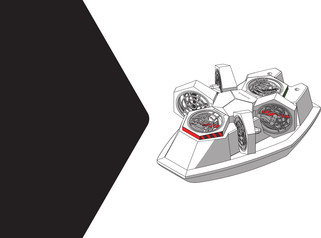
Makeblock MC-6A Airblock User Manual
Makeblock Co., Ltd. Airblock Users Manual
Users Manual

D1.2.11_7.40.4600
Technical support:
tec-support@makeblock.com
www.makeblock.com
@Makeblock
@Makeblock
@Makeblock
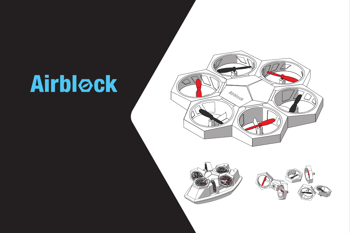
The Modular & Programmable Drone
USER MANUAL
P02
P03
P04
P05
P06
P10
P12
P18
P27
P31
Downloading the Software
Parts List
Introduction to Master Controller Module
Introduction to Battery
Introduction to Power Module
Introduction to Stickers
Aircraft Mode User Guide
Hovercraft Mode User Guide
Custom Mode User Guide
FAQs
Table of Contents
·Operating Environment ·Items to Note
·Installation Steps ·Controls
·Operating Environment ·Items to Note
·Installation Steps ·Controls
·Methods to Use ·Operating Environment
·Items to Note ·Programming

02
Downloading the Software A tablet or smartphone is required to control the Airblock.
App Store Download
Ocial Website Download
Search "Makeblock" and install the application from app store.
http://learn.makeblock.com/en/software/
Login to download the corresponding version of application.
System and Device Requirements
iOS devices (including iPhone5, iPad mini, iPad 3 or later models)need to support iOS 9.0 or
above versions.Android devices need to support Android 4.1 or above versions.
Apple, the Apple logo, iPad and iPhone are trademarks of Apple Inc, registered in the U.S.
and other countries.
App Store is a service mark of Apple Inc.
Android and the Google logo are trademarks of Google Inc.
03
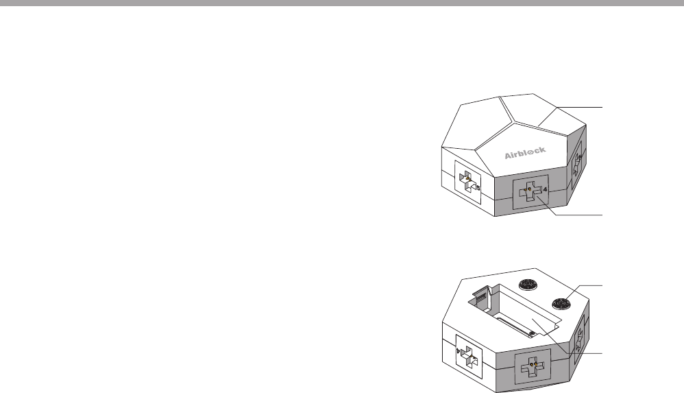
Parts List
Master Controller Module
Power Modules Hovercraft Base Protective Cover
Battery Charger
Charging
Cable
04
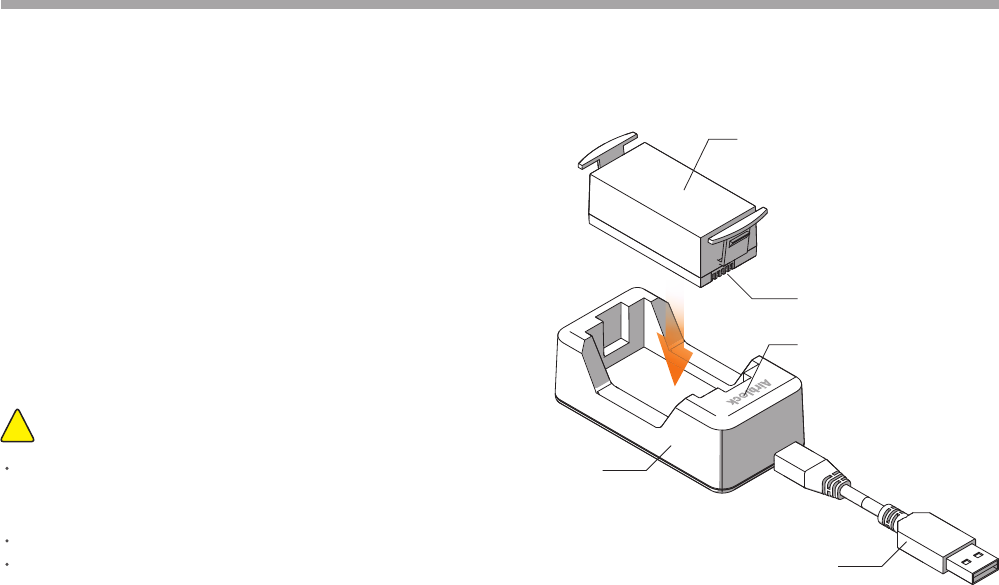
The master controller module includes components such as
6 power module plug-in sockets, 3 colored light indicators,
ultrasonic sensor, barometer, gyroscope, Bluetooth,
microcontroller chip, etc.
Ultrasonic sensor: for measuring distance. Works together with
the barometer to sense the height change value of the aircraft.
Colored light indicator: functions as power supply indicator.
Brightness and color of light may be adjusted on the
application program.
The following sensors are built-in:
Barometer: senses height changes.
Gyroscope: senses position and orientation of master
controller module.
Bluetooth Module: real-time data collected by sensors can be
read by the application program after establishing Bluetooth
connection to tablet or smartphone.
6
5
Front View
Back View
Colored Light
Indicator
Ultrasonic Sensor
Plug-in Socket
Battery
Compartment
Introduction to Master Controller Module
05
Airblock does not have a power switch. When a battery with
sucient power is inserted into master controller module, the
master controller module automatically enters standby mode.
When inserting battery into master controller module or
battery charger, please ensure that the contact points are
placed in the correct direction.
Charger will display a red light while battery is charging, and a
green light when battery is fully charged.
Items to Note:!
USB Cable (5V input)
Battery
Battery Contact Points
Indicator Light
Charger
Battery
If unused for an extended period of time, battery should
be removed from the master controller module to prevent
damage due to battery leakage.
Do not charge battery for more than 12 hours.
Do not use battery in places of high temperature and high
humidity. Exposure of battery to excessive shock or impact
may result in battery malfunction or explosion.
06
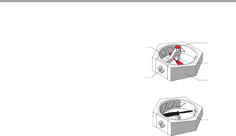
Introduction to structure
The Power Module is made up of parts such as the motor,
propellers, plug, frame, etc.
Indicator light installed within the frame will light up when
motor starts running.
The light indicator and foot pad of the aircraft head power
module are red. For other power modules, the foot pad is
black and light indicator is green.
Frame
Foot Pad
Motor
EPP Protective Ring
Propeller
Plug
Power Module
07
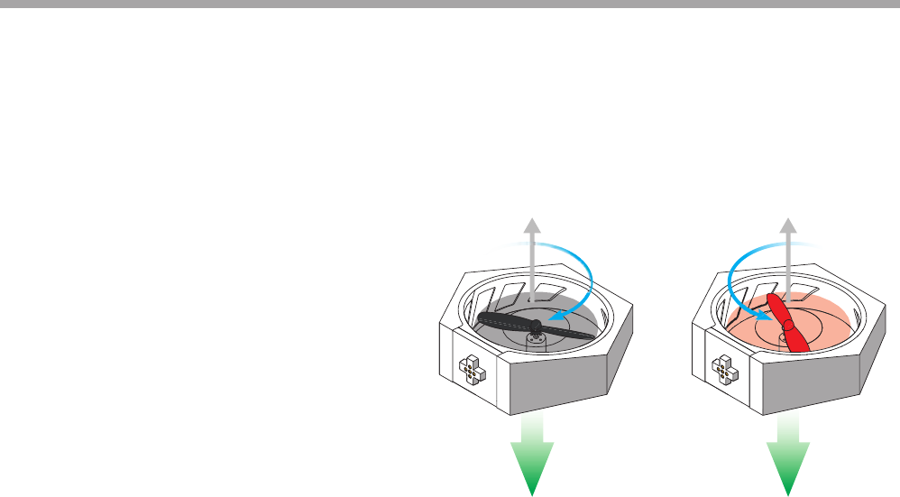
Introduction to Operating Principles
In order to oset the self-rotation of the aircraft, the
propellers are classied as black clockwise rotating
propellers and red counter-clockwise rotating propellers;
the motors are classied as clockwise rotating and
counter-clockwise rotating as well. After successful
connection to the master controller module, the motor
will start spinning, thus pushing air downwards which in
turn generates an upward thrust.
Direction of thrust
Direction of air current Direction of air current
Direction of thrust
Clockwise rotation Counter-clockwise
rotation
Power Module
08
Standard Angle
90°
180°
270°
Installation Angle
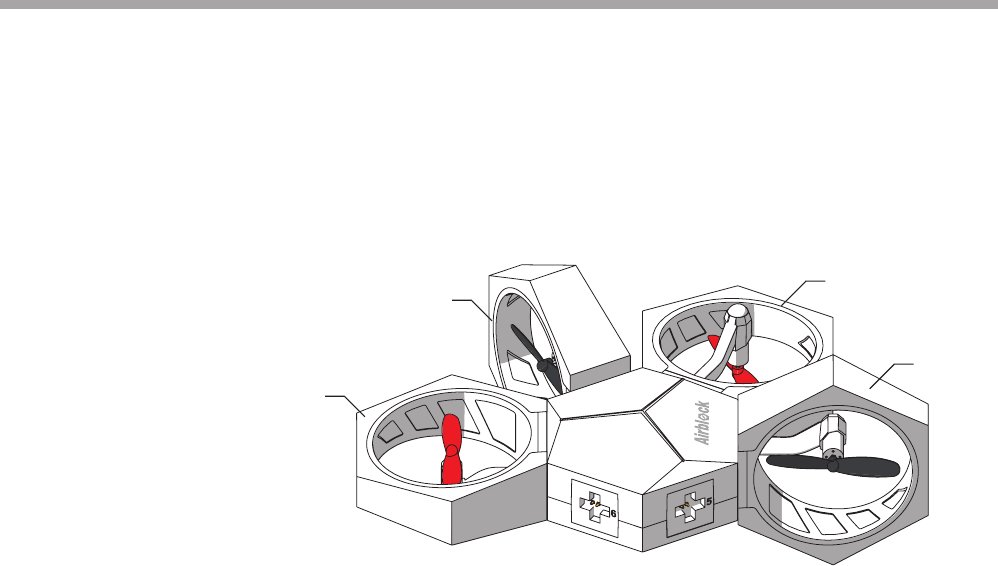
Each power module may be installed onto its
corresponding port on the master controller
module at 4 dierent angles.
Power Module
09
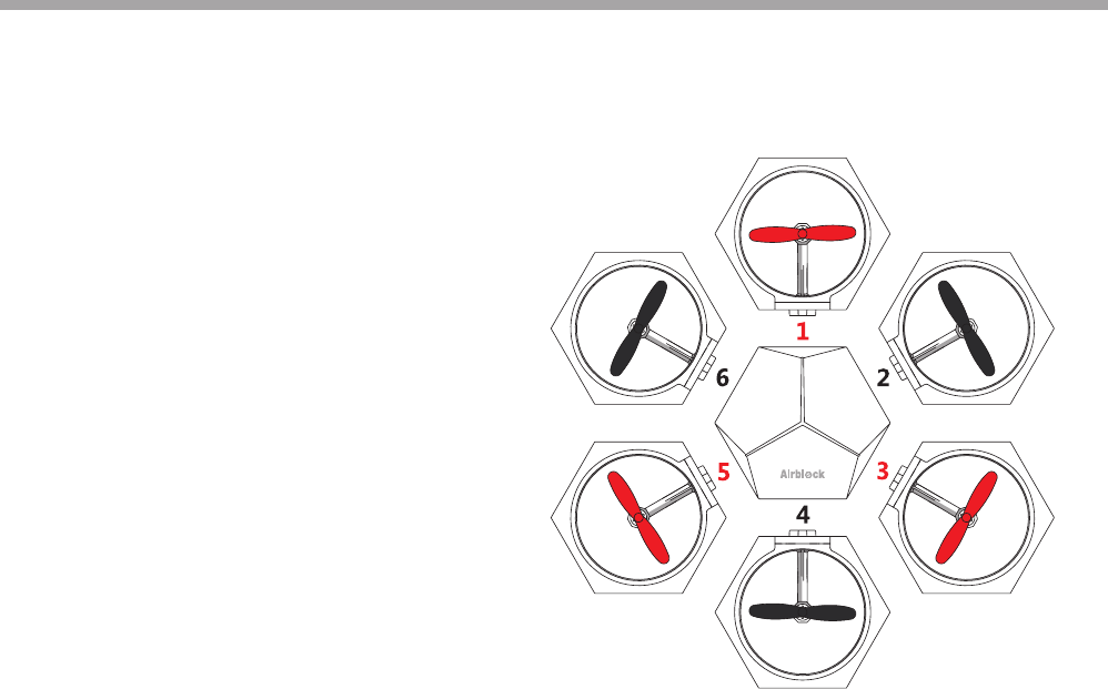
Port Numbers
Install red propeller power module onto Port 1, 3, 5
respectively (aircraft head module with red foot pad will
be installed onto Port 1).
Install black propeller power module onto Port 2, 4, 6
respectively.
Power Module
10
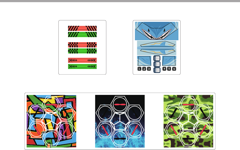
Power Module Stickers Hovercraft Stickers
Fuselage Stickers(Random gift. The picture is for reference only, please make the object as the standard.)
Stickers
11
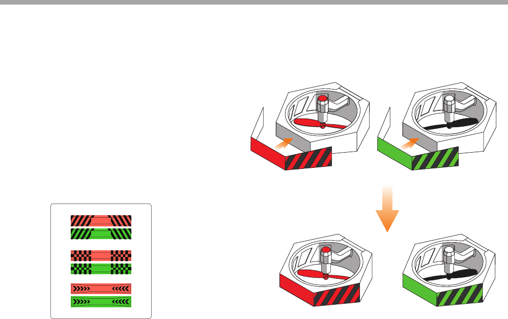
Power Module Stickers:
Attach to the side of power module, in order to better
distinguish the direction of fuselage in ight.
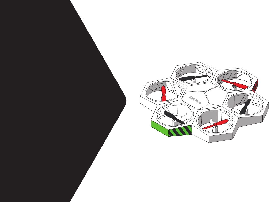
It is recommended to attach red sticker to the aircraft
head power module (Position 1) and green sticker to a
black propeller power module (Position 4). The other
power modules do not need stickers.
There are 3 dierent styles of stickers -- you can choose
which to use.
Stickers
Aircraft
User Guide
13
Aircraft User Guide
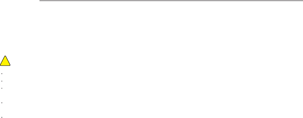
Items to Note:
!
Space larger than 3x3x3 meters are recommended for indoor ying.
Land surfaces: aircraft should take o from relatively hard and at surfaces. Soft surfaces such as carpets and grass may cause
interference to the ultrasonic sensor.
Water surfaces: do not operate aircraft on water surfaces, or y aircraft in the air above water surfaces. This is to prevent occurrences
of a short circuit which may cause re damage to the machine if accidentally dropped into the water.
Outdoors: a windy outdoor environment may interfere with the aircraft's normal ight.
Before starting, make sure the module is assembled correctly and the protective cover is not installed. The protective cover aects
airow and will cause the aircraft not to take o. Place aircraft on the open ground, ensuring there are no obstacles within a 2 meter
radius.
If you press the power button during ight, the aircraft will immediately drop, which may damage the equipment.
More space is needed when performing ight stunts in order to avoid collisions.
Motor and propellers rotating at high speeds may cut people or animals, or become entangled in their hair or fur. Please move away
from people and animals before operating Airblock.
Dust, hair, fur, or water trapped in Airblock may result in motor malfunction or damage to electronic parts.
Operating Environment
14
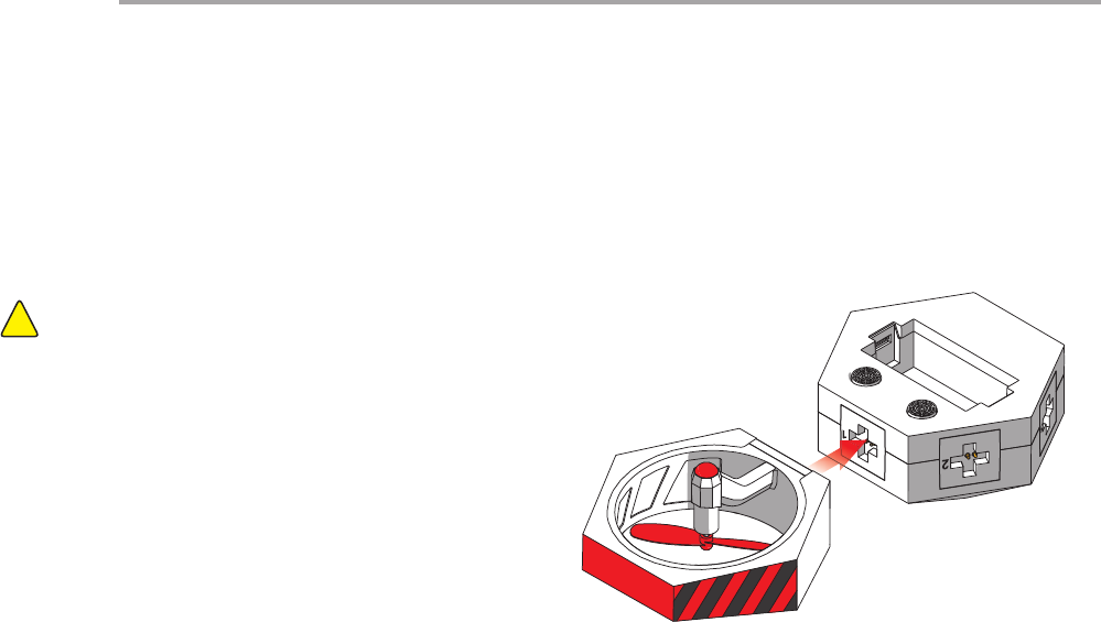
If head module is installed in the incorrect position, it will not
properly control the direction of ight.
Note:!
Installing the aircraft head power module
Install aircraft head power module with red foot pad onto
Port 1 of the master controller module.
Installation Step 1
Aircraft User Guide
15
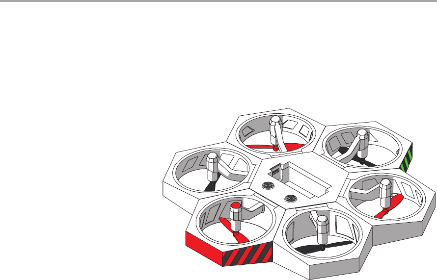
Installing the other power modules
Install the remaining power modules in sequence
onto the master controller module.
Installation Step 2
Aircraft User Guide
16
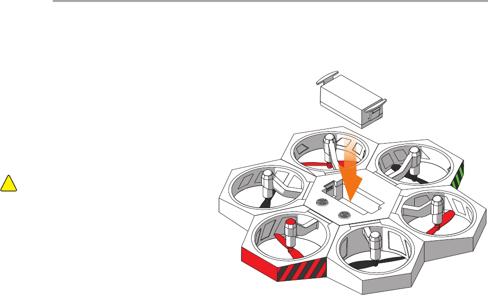
Direction of battery
contact points
Installing the battery
After fully charged battery is inserted, Airblock
automatically turns on and enters standby mode. The
top indicator light of master controller module will turn
on and display a white light. When Bluetooth connection
is successful, the light will turn red.
Installation Step 3
Aircraft User Guide
Before actually taking o, please ensure Airblock has
its top facing upward and is placed on at ground. The
picture on the right shows the bottom part of Airblock.
Items to Note:
!
17
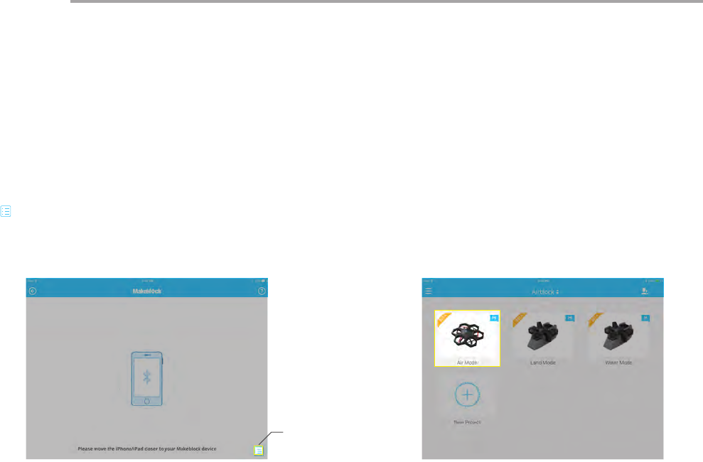
Open aircraft control interface after successful connection is
made. (Note: interface or icons may vary after each software
update. Please follow the interface of the latest download.
This instruction manual is for reference purposes only.) Follow
procedures on the New User Guide to familiarize yourself with
the functions of the dierent keys and learn how to use Airblock.
Aircraft User Guide
Step 1 Step 2
Follow the instructions on the rst page of User Guide to
download and install the application. Open the Makeblock
application and move tablet or smartphone within close
distance to running Airblock, Bluetooth connection should be
paired automatically. If connection is not successful, tap the list
" " icon on the bottom right hand side of the touchscreen and
select manually.
Controls
List
Hovercraft
User Guide
19
Hovercraft User Guide
Items to Note:
!
Recommended for use on at, level land surfaces.
Software: App controls are separate for land and water modes. Make sure to select the corresponding mode for your environment.
Land surfaces: do not drive or y hovercraft on muddy surfaces, uneven surfaces, or mesh oors.
Water surfaces: do not drive or sail hovercraft on water surfaces with waves or obstacles. Control range via Bluetooth is limited; do
not use Hovercraft over wide area on water surfaces.
Motor and propellers rotating at high speeds may cut people or animals, or become entangled in their hair or fur. Please move away
from people and animals before operating Airblock.
Dust, hair, fur, or water trapped in Airblock may result in motor malfunction or damage to electronic parts.
Operating Environment
20
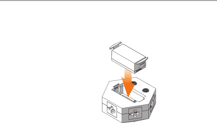
Direction of battery contact points
Installing the battery
Installation Step 1
Hovercraft User Guide
21
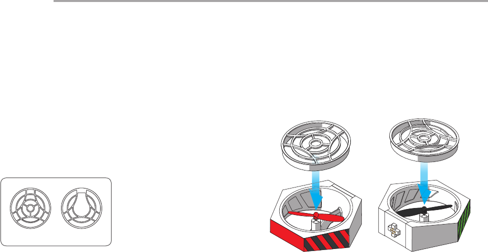
Top Bottom
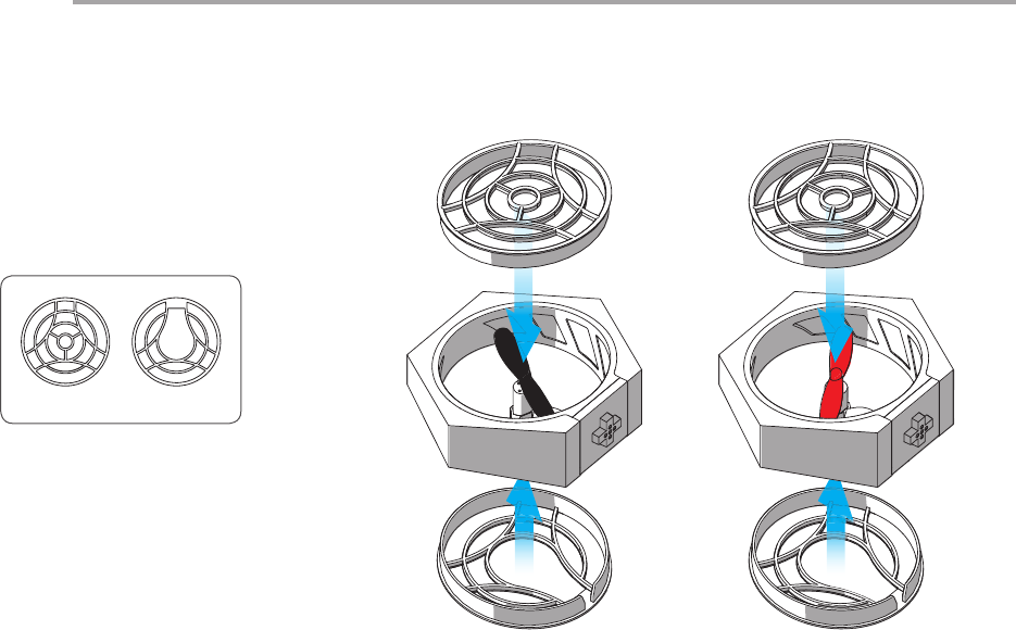
Installing the protective cover
Installation of protective covers is required in Hovercraft mode to
protect propellers from damage and to prevent propellers from
causing damage.
Protective covers are required only on top part of the power modules
at Port 1 and 4.
There are two types of protective covers; take note during installation.
Installation Step 2
Hovercraft User Guide
22
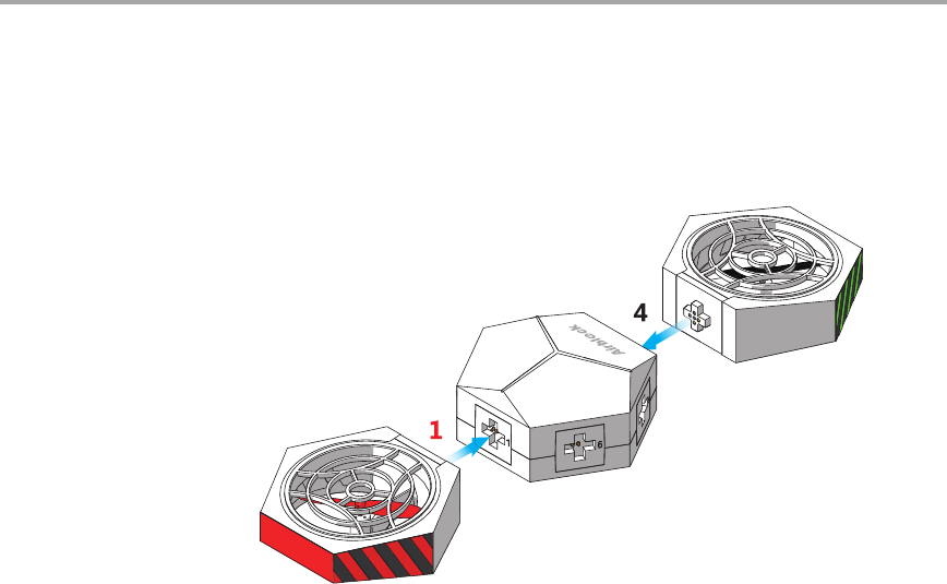
Connect the aircraft head power module and a black propeller power module
to Port 1 and 4 on the master controller module respectively.
Installation Step 3
Hovercraft User Guide
23
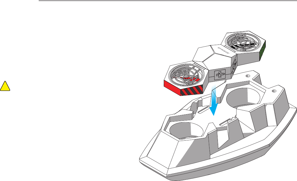
Port 1 faces forwards (the smaller end of the hull is the bow)
If the master controller module is installed in the incorrect
direction, it will not be able to control the direction of the
hovercraft.
Note:!
After connecting power modules to the master controller module, t
the master controller module onto the hovercraft hull.
Installation Step 4
Hovercraft User Guide
24
Protective covers are required on both the top and
bottom parts of the other power modules.
There are two types of protective covers; take note
during installation.
Installation Step 5
Top Bottom
Hovercraft User Guide
25
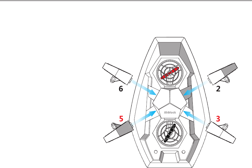
After tting the protective covers, attach the 4 power modules
onto master controller module according to the directions in
diagram below. Check that the protective covers are tted in
the accurate places and that the power modules are attached
securely to the master controller module.
Installation Step 6
Hovercraft User Guide
26
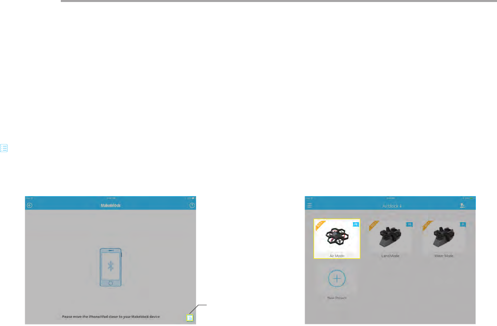
Open hovercraft control interface after successful connection
is made. (Choose Land or Water Mode according to the
corresponding environment. Incorrect mode selection may
cause safety problems; pay attention! Software interface or icons
may vary after each software update. Please follow directions
of the latest download. This instruction manual is for reference
purposes only.)
Follow procedures on the New User Guide to familiarize yourself
with the functions of the different keys and learn how to use
Airblock.
Follow the instructions on the first page of User Guide to
download and install the application. Open the Makeblock
application and move tablet or smartphone within close
distance to running Airblock, Bluetooth connection should be
paired automatically. If connection is not successful, tap the list
" " icon on the bottom right hand side of the touchscreen and
select manually.
Step 1 Step 2
Controls
Hovercraft User Guide
List
Custom Mode
User Guide
Methods to Use
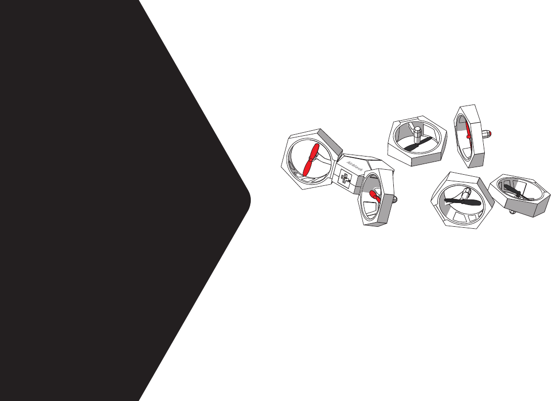
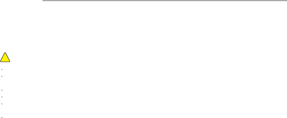
You may connect the power modules to the master controller
module at dierent angles and use the Airblock as a propeller
and blower according to your own creativity. Propulsion forces in
dierent directions and wind speeds of varying intensity may be
achieved by setting the motor at dierent rotating speeds in the
programming application.
28
Items to Note:
!
Recommended for use on at, clean oors or tables.
Land surfaces: it is best to use Airblock on smooth, at, and level land surfaces.
Water surfaces: only the hovercraft may be placed in the water. Use of Airblock in other forms on water surfaces must not be in
contact with water. Dropping the Airblock into water by accident may result in re damage due to a short circuit.
In the air: Airblock is unable to y normally in Custom Mode.
Keep a distance of at least 2 meters from people or animals before running Airblock.
Motor and propellers rotating at high speeds may cut people or animals, or become entangled in their hair or fur. Please move away
from people and animals before operating Airblock.
Dust, hair, fur, or water trapped in Airblock may result in motor malfunction or damage to electronic parts.
Operating Environment
Custom Mode User GuideCustom Mode User Guide
29
Custom Mode User Guide
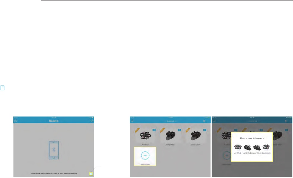
Tap on the "New Project" option and select "Customize" to
create a new program for controlling Airblock.
Step 1 Step 2
Follow the instructions on the rst page of User Guide to
download and install the application. Open the Makeblock
application and move tablet or smartphone within close
distance to running Airblock, Bluetooth connection should be
paired automatically. If connection is not successful, tap the list
" " icon on the bottom right hand side of the touchscreen and
select manually.
Programming
List
30
Custom Mode User Guide
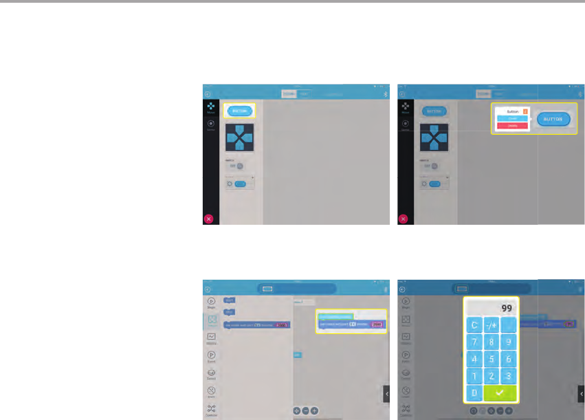
In "DESIGN" mode, drag and drop required keys
modules into the edit section on the right. Tap on the
module to enter into "Code" mode.
In "Code" mode, drag the motor speed block to "When
button pressed" and enter the corresponding number
to set the motor speed.
At the same time, make sure the motor speed is "0"
for "when button released", otherwise the motor may
continue uncontrolled, causing danger.
Step 3
Step 4

31
To optimize user experience, we will continue to upgrade the
software. After connecting to the device Bluetooth, you can
click the setting iron on the upper left corner of application,
select the rmware information to view the current rmware
version of the device. If there is an upgrade, you may click the
upgrade. If the upgrade fails, you can try to upgrade again
after connecting to the device Bluetooth.
Common Problems
Propellers are not spinning
Poor connection
Motor axis is stuck
Switch o Bluetooth connection
Application settings error
1. Check if the connection of the power module and master
controller module is too widely-spaced, if connection is
uneven, or if foreign matter is present.
2. Check if the contact points of the metal spring pins have
oxidized or are damaged.
Check if any foreign matter is tangled on the motor's axis;
remove foreign matter.
Use application to reconnect to Bluetooth.
When programming the motor in Custom Mode, if the motor
does not start when application is launched, check if the port
numbers in the block are correct.
Firmware upgrade
Direction is incorrect
Aircraft head module is installed in the wrong position
1. When in Aircraft mode, if you encounter problems
controlling the direction, check if aircraft head module with
red light indicator is in the wrong position. Follow installation
steps in User Guide and re-install.
2. When in Hovercraft mode, check if the master controller
module is installed in the correct direction. Follow installation
steps in User Guide and re-install.

32
Power supply indicator light does not light up
Battery has no power
Incorrect battery installation
Static electricity causing abnormality
Try again after charging battery for half an hour or longer.
Battery is installed upside down or in the incorrect location.
Re-install battery using the correct method and conrm that
battery is installed in proper place.
Static electricity may cause an abnormal shutdown. Remove
the battery to reinstall.
Aircraft is unable to take o
Power supply is insucient
Protective cover is not removed
Power module is installed in the wrong direction
After successful connection to the application, you may
check the power supply level in the control interface. If power
supply is less than 20%, please charge the battery.
Protective cover must be taken o for Aircraft mode.
Protective cover is only applicable for use in Hovercraft mode.
Check all power modules; the foot pad side must be facing
downwards.
Common Problems

Any Changes or modications not expressly approved by the party responsible for compliance could void the user's authority to operate the equipment.
Note: This equipment has been tested and found to comply with the limits for a Class B digital device,pursuant to part 15 of the FCC Rules. These limits are designed to provide
reasonable protection against harmful interference in a residential installation. This equipment generates uses and can radiate radio frequency energy and, if not installed and
used in accordance with the instructions, may cause harmful interference to radio communications. However, there is no guarantee that interference will not occur in a particular
installation. If this equipment does cause harmful interference to radio or television reception, which can be determined by turning the equipment o and on, the user is
encouraged to try to correct the interference by one or more of the following measures:
-Reorient or relocate the receiving antenna.
-Increase the separation between the equipment and receiver.
-Connect the equipment into an outlet on a circuit dierent from that to which the receiver is connected.
-Consult the dealer or an experienced radio/TV technician for help.
The device has been evaluated to meet general RF exposure requirement. The device can be used in portable exposure condition without restriction.
- Small parts. Not for children under 3 years.
Age
8+
WARNING:
CHOKING HAZARD
Children to use only under adult's supervision.