Makita BHP456(LXPHOL*1) BDF452 NP User Manual To The 6da62906 D876 40e0 A23e Ff8a74ef895c
User Manual: Makita BHP456(LXPHOL*1) to the manual
Open the PDF directly: View PDF ![]() .
.
Page Count: 10
P 1/10
Model No.
Description
CONCEPT AND MAIN APPLICATIONS
Specification
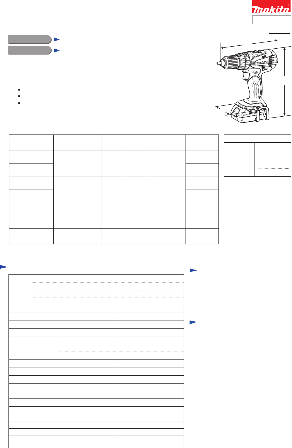
Dimensions: mm (")
Width (W)
Height (H)
Length (L) 206 (8-1/8)
79 (3-1/8)
234 (9-1/4)*2
251 (9-7/8)*3
BHP456 (LXPH01*1)
Cordless Hammer Driver Drill
Battery
Capacity of drill chuck: mm (")
Capacity: mm (")
Lock torque: N.m (in.lbs)
Electric brake
Variable speed control
Mechanical speed control
Reversing switch
Max. fastening
torque: N.m (in.lbs)
Torque setting
Steel
Wood
Soft joint
Hard joint
No load speed: min-1=rpm
Cell
Voltage: V
Capacity: Ah
Low/ High
Standard equipment
Optional accessories
Note:
The standard equipment for the tool
shown above may vary by country.
Fast charger DC18RA,
Charger DC18SD,
Charger DC24SC (for all countries
except North American countries),
Automotive Charger DC18SE,
Battery BL1815,
Battery BL1830,
Drill bits for wood,
Drill bits for steel,
Drill bits for masonry,
Belt clip,
Bit holder
+ - bit 2-45 ........ 1
Belt clip ............ 1
Weight according to
EPTA-Procedure 01/2003*4: kg (lbs)
Max output: W
Li-ion
Charging time (approx.): min. 15/ 22 with DC18RA
18
1.3/ 3.0
Yes
Yes
Yes (2 speed)
Yes
Yes
1.6 (3.4)*2/ 1.8 (4.0)*3
13 (1/2)
38 (1-1/2)
Masonry 13 (1/2)
16 stage + drill mode
54 (480)
36 (320)
50 (440)
0 - 400/ 0 - 1,500
Low/ High 0 - 6,000/ 0 - 22,500
1.5 (1/16) - 13 (1/2)
300
Model BHP456 (LXPH01) is the improved version of model BHP452, featuring;
More compact and lightweight design than BHP452
More comfortable operation will be provided by re-designed ergonomic grip
Compatible with the 18V Li-ion batteries equipped with the Battery protection
circuit designed to protect the battery from damages due to overdischarge,
high temperature or overload current
This new product is available in the following variations.
Model number in parentheses is for North and Central American countries.
All models also include the accessories listed below in "Standard equipment".
Housing
color
*2: with Battery BL1815
*3: with Battery BL1830
BHP456RFE
(LXPH01)
BHP456RFEW
(LXPH01W)
DC18RA
Model No. Type Quantity Charger Plastic
carrying case
Battery
cover
Yes
No
2
Battery
BHP456Z
(LXPH01Z)
BL1815 DC18RA Yes
BHP456RHE
(LXPH01C)
BL1830
2
1
No No
1
BHP456SHE DC18SD Yes2BL1815 1
BHP456SHEW
BHP456ZW
(LXPH01ZW)
Makita blue
white
Makita blue
Makita blue
white
white
No No
Makita blue
white
BHP456RHEW
(LXPH01CW)
PRODUCT
LED job light
*1 Model number for North and Central American countries
(with Battery BL1815)
*2: with Battery BL1815, *3: with Battery BL1830
*4 with the lightest battery available for the model
TECHNICAL INFORMATION
H
L
W
Impacts per minute: min-1= rpm
Clutch torque setting: N.m (in.lbs) 1.0 - 5.0 (9 - 44)
P 2/10
Repair
CAUTION: Repair the machine in accordance with “Instruction manual” or “Safety instructions”.
[1] NECESSARY REPAIRING TOOLS
[2] LUBRICATIONS
[3] DISASSEMBLY/ASSEMBLY
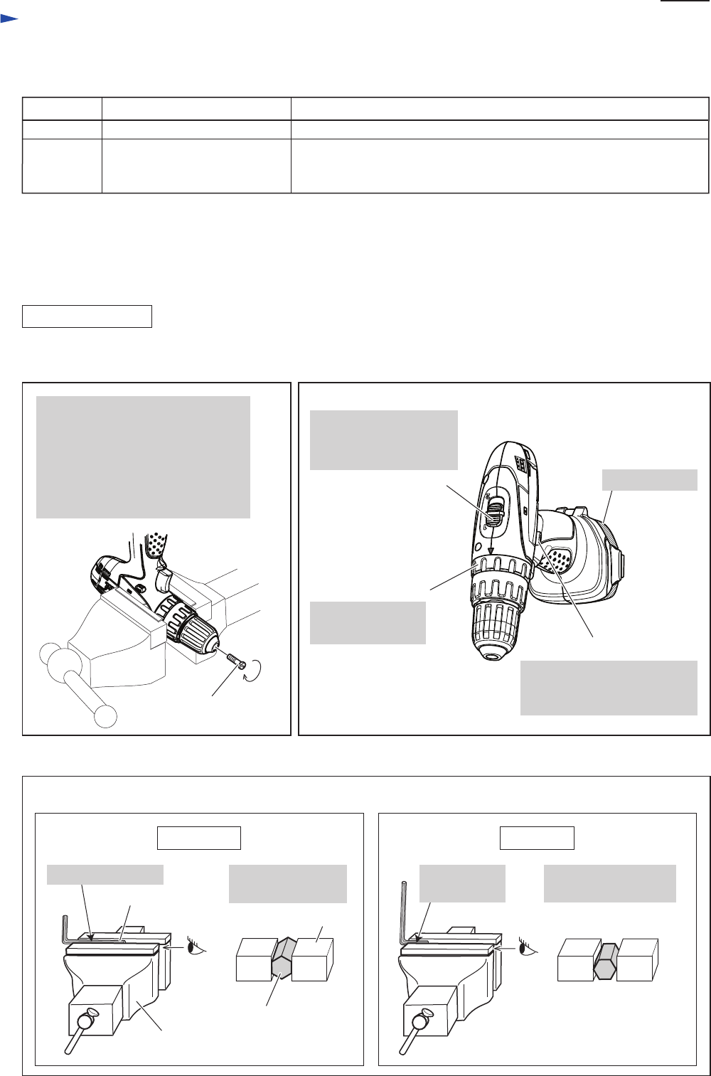
[3]-1. Drill chuck
Code No.
1R359
Description Use for
Hex wrench 10 Removing / Assembling drill chuck
Drill chuck removing tool
Removing Drill chuck
(Use this tool if Drill chuck cannot be removed by the method
described in “ [3]-1. Drill chuck disassembling”.)
DISASSEMBLING
Lubrications are not required as Gear section is replaced as a factory-lubricated gear unit.
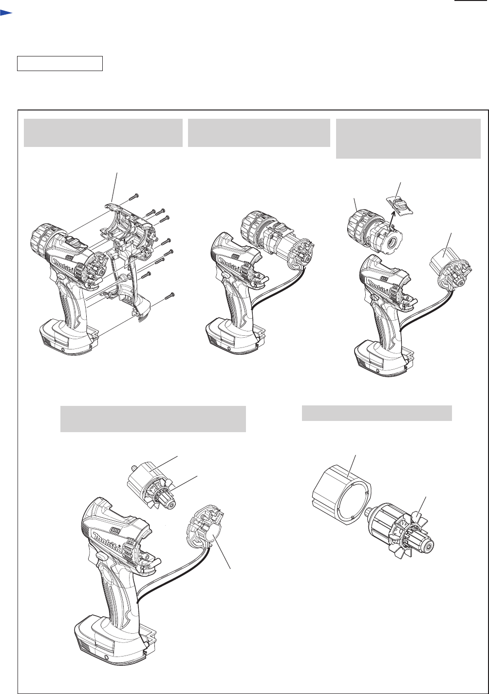
(1) Set Machine and Repairing tools. (Figs. 1, 2, 3)
CORRECT WRONG
Fig. 3
Fig. 1 Fig. 2
Note:
Use Impact driver to unscrew
M6 x 22 Flat head screw if it
could not be removed manually.
Open Keyless drill chuck fully and
remove M6 x 22 Flat head screw
by turning it clockwise.
M6 x 22 Flat head screw
F/R Change lever
Set Speed change lever
to Low speed mode
indicated by "1".
Set Change ring
to Drill mode.
Speed change lever
Change ring
Set F/R Change lever to
Reverse (counterclockwise)
rotation.
Attach battery.
Setting of Hex wrench 10
Vise
Grip flat surfaces
of Hex wrench 10.
Hex wrench 10
Hex wrench 10,
viewed from side [A]
Vise
Grip the long end.
[A]
Do not grip edges of
Hex wrench.
Do not grip
the short end.
P 3/10
Repair
[3] DISASSEMBLY/ASSEMBLY
[3]-1. Drill chuck (cont.)
DISASSEMBLING
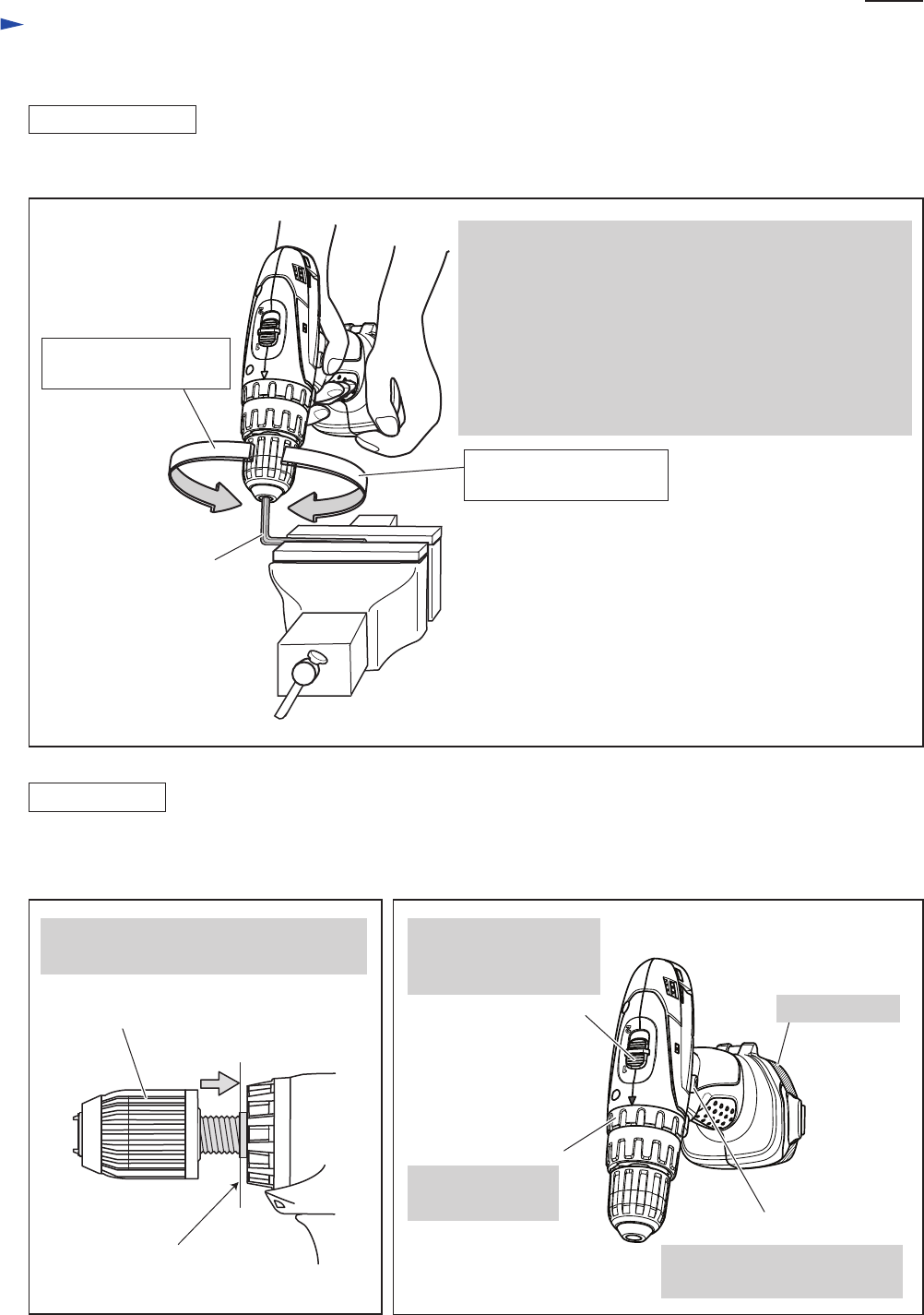
(2) Remove Drill chuck. (Fig. 4)
*Note: The rotational direction is viewed from operator.
1. Grip Hex wrench 10 with Drill chuck and hold Machine.
Important:
Be sure to hold the grip of Machine tightly with sufficient
counterclockwise* force against clockwise* recoil force
of Machine.
2. Pull Switch trigger slowly.
3. Spindle rotates counterclockwise* and consequently
Drill chuck is removed from spindle.
Hex wrench 10
Fig. 4
ASSEMBLING
Fig. 5 Fig. 6
end of the threaded
portion of Spindle
Drill chuck
(1) Set the machine. (Figs. 5, 6)
(2) Set Hex wrench 10 to vise as described in Fig. 3.
Turn Drill chuck clockwise until it sits on
the end of the threaded portion of Spindle.
F/R Change lever
Set Speed change lever
to Low speed mode
indicated by "1".
Set Change ring
to Drill mode.
Speed change lever
Change ring
Set F/R Change lever to
Forward (clockwise) rotation.
Attach battery.
Counterclockwise* force
to be applied by operator
Clockwise* recoil force
of Machine
P 4/10
Repair
[3] DISASSEMBLY/ASSEMBLY
[3]-1. Drill chuck (cont.)
(3) Tighten Drill chuck. (Fig. 7)
ASSEMBLING
DISASSEMBLING
Hex wrench 10
Fig. 7
Fig. 8
M6x22 Flat head screw
4. Open Keyless drill chuck fully,
then drive M6x22 Flat head screw
by turning counterclockwise*
with Impact driver.
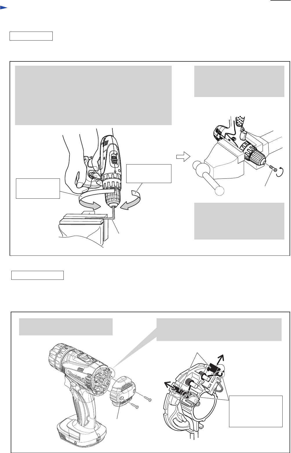
[3]-2. Gear assembly and Motor section
Rear cover
1. Unscrew two 3x16 Tapping screws,
then remove Rear cover.
2. Pull Carbon brushes in the direction of the arrow
after shifting the end of each Torsion spring from
the top of Carbon brushes.
Carbon brushes
(1) First, remove Drill chuck. (Figs. 1, 2, 3, 4)
(2) Then remove Rear cover and disconnect Carbon brushes from Armature’s Commutator
before dismantling Housing set. (Fig. 8)
Counterclockwise
recoil force
of Machine
*Note: The rotational direction is viewed from operator
1. Grip Hex wrench 10 with Drill chuck and hold Machine.
Important:
Be sure to hold the grip of Machine tightly with sufficient
clockwise* force against counterclockwise* recoil force
of Machine.
2. Pull Switch trigger slowly to turn Spindle clockwise*.
3. Drill chuck is tightened and consequently Spindle is locked.
Clockwise* force
to be applied by
operator
Shift the end of each
Torsion spring to the
concave portion of
Brush holder.
Note:
Apply adhesive (ThreeBond 1321B/
1342 or Locktite 242 to threaded
portion) when re-using removed
M6x22 Flat head screw.
P 5/10
Repair
[3] DISASSEMBLY/ASSEMBLY
[3]-2. Gear assembly and Motor section
(3) Disassemble Gear assembly and Motor section. (Fig. 9)
Fig. 9
DISASSEMBLING
3. Unscrew nine 3x16 Tapping screws,
then remove Housing (R).
4. Remove the assembly of
Motor section and Gear section.
Housing (R)
5. Remove Speed change lever,
then separate Gear assembly
from Motor section.
6. Remove Armature along with Yoke unit
from Brush holder complete.
Gear assembly
Brush holder
complete
Armature
Yoke unit
Armature
7. Pull Armature from Yoke unit.
Yoke unit
Motor section
Speed change lever
P 6/10
Repair
[3] DISASSEMBLY/ASSEMBLY
[3]-2. Gear assembly and Motor section (cont.)
(4) Insert Armature into Yoke unit carefully and connect Motor section to Gear assembly. (Fig. 11)
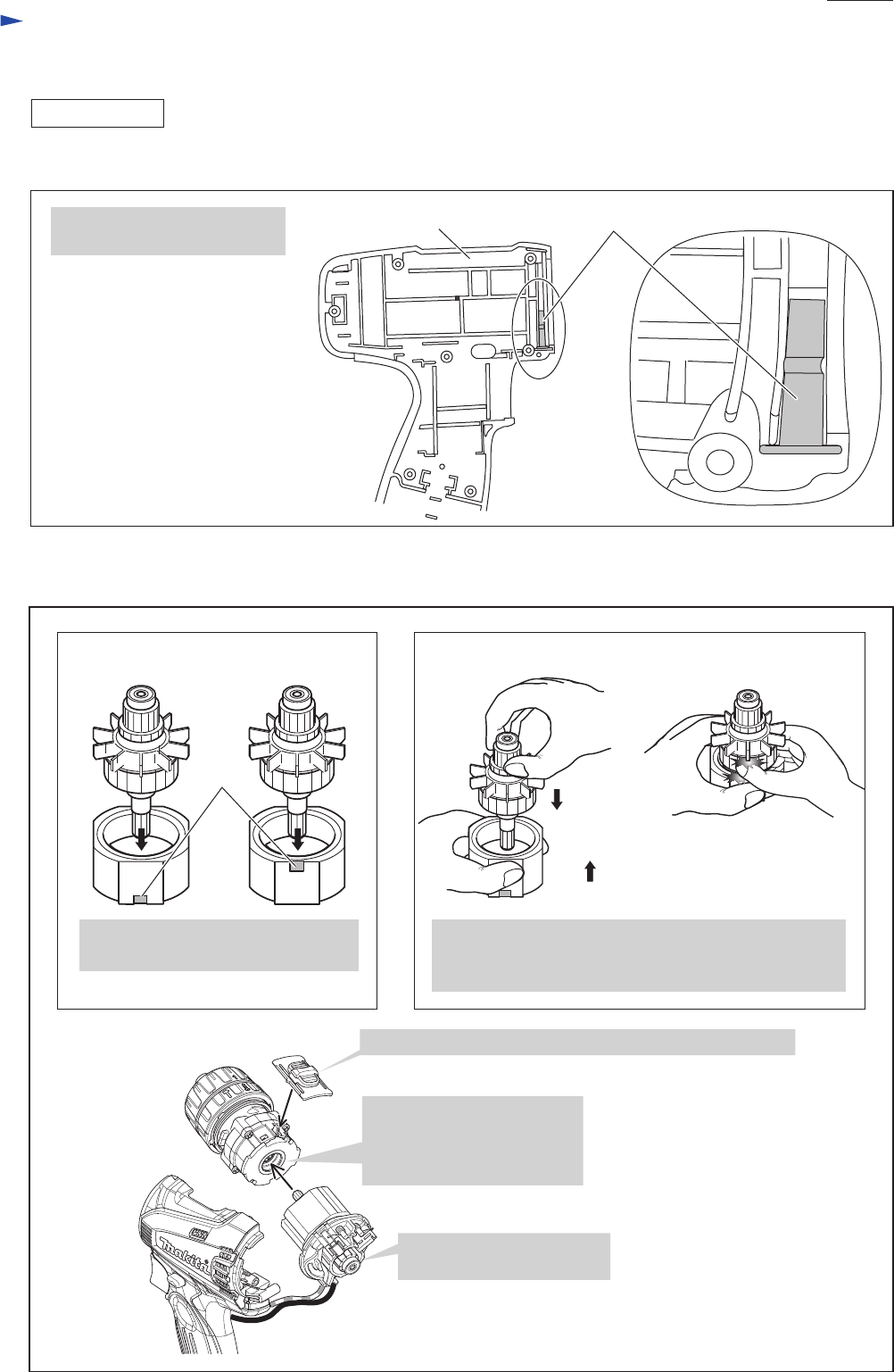
(3) Put Leaf spring in place on the inside of Housing (L). (Fig. 10)
Fig. 11
Fig. 10
ASSEMBLING
1. Insert Commutator end
into Brush holder complete.
3. Mount Speed change lever to Gear assembly. (Refer to Fig. 14)
notch
Be sure to put Leaf spring
in place as drawn on the right.
Notch must be located on Armature
drive-end as above.
[Wrong][Correct]
Note: Be careful when inserting
Armature as fingers can
be pinched and injured.
[Wrong][Correct]
Be sure to hold Commutator portion as your fingers
can be pinched by Armature fun due to strong magnetic
force toward Yoke unit.
2. Connect Motor section to
Gear assembly by engaging
Armature gear with Planetary
gears in Gear assembly.
Leaf spring Housing (L)
P 7/10
Repair
[3] DISASSEMBLY/ASSEMBLY
[3]-2. Gear assembly and Motor section (cont.)
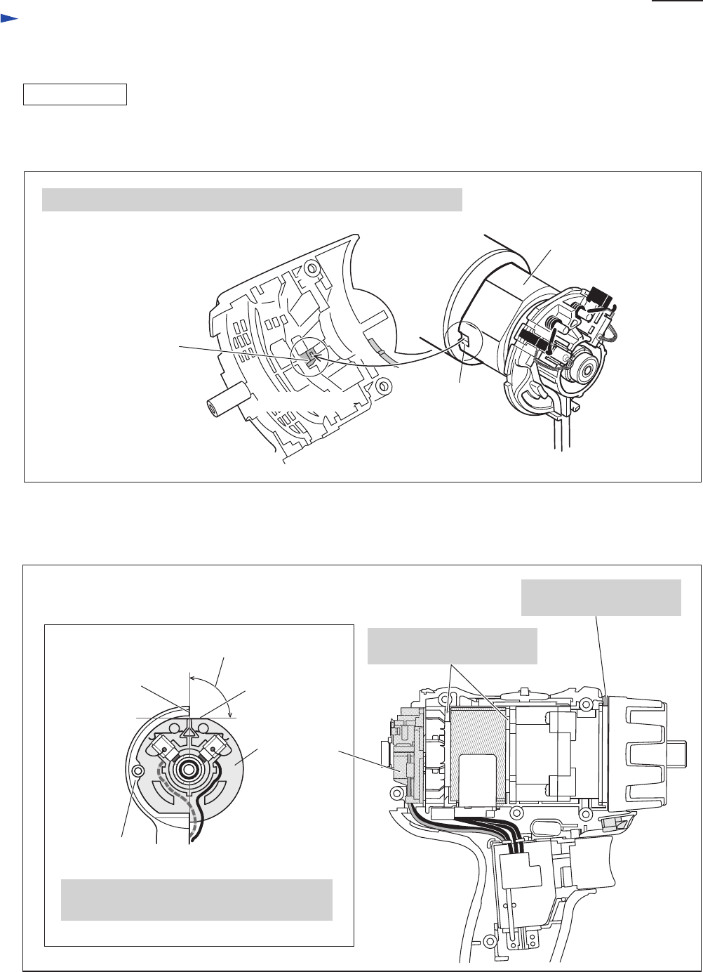
(5) Engage the notch of Yoke unit with the projection inside of Housing (L) when mounting the assembly of Gear section
and Motor section to Housing (L). (Fig. 12)
(6) Adjust the assembly of Motor section and the Gear section to the correct position in Housing (L)
so as to assemble Housing (R) to Housing (L) smoothly and exactly. (Fig. 13)
Fig. 12
Fig. 13
ASSEMBLING
projection for fitting
to the notch
Engage the notch of Yoke unit with the projection inside of Housing (L).
Housing (L) notch
Yoke unit
The flat portion of Brush holder must be at
exactly 90 degrees to the edge of Housing (L).
edge of
Housing (L)
Brush holder
complete
Housing (L)
flat portion of
Brush holder
complete
90 degrees Yoke unit must be mounted
within these ribs.
This rib must be fit in
the groove of Change ring.
P 8/10
Repair
[3] DISASSEMBLY/ASSEMBLY
[3]-3. Speed change lever
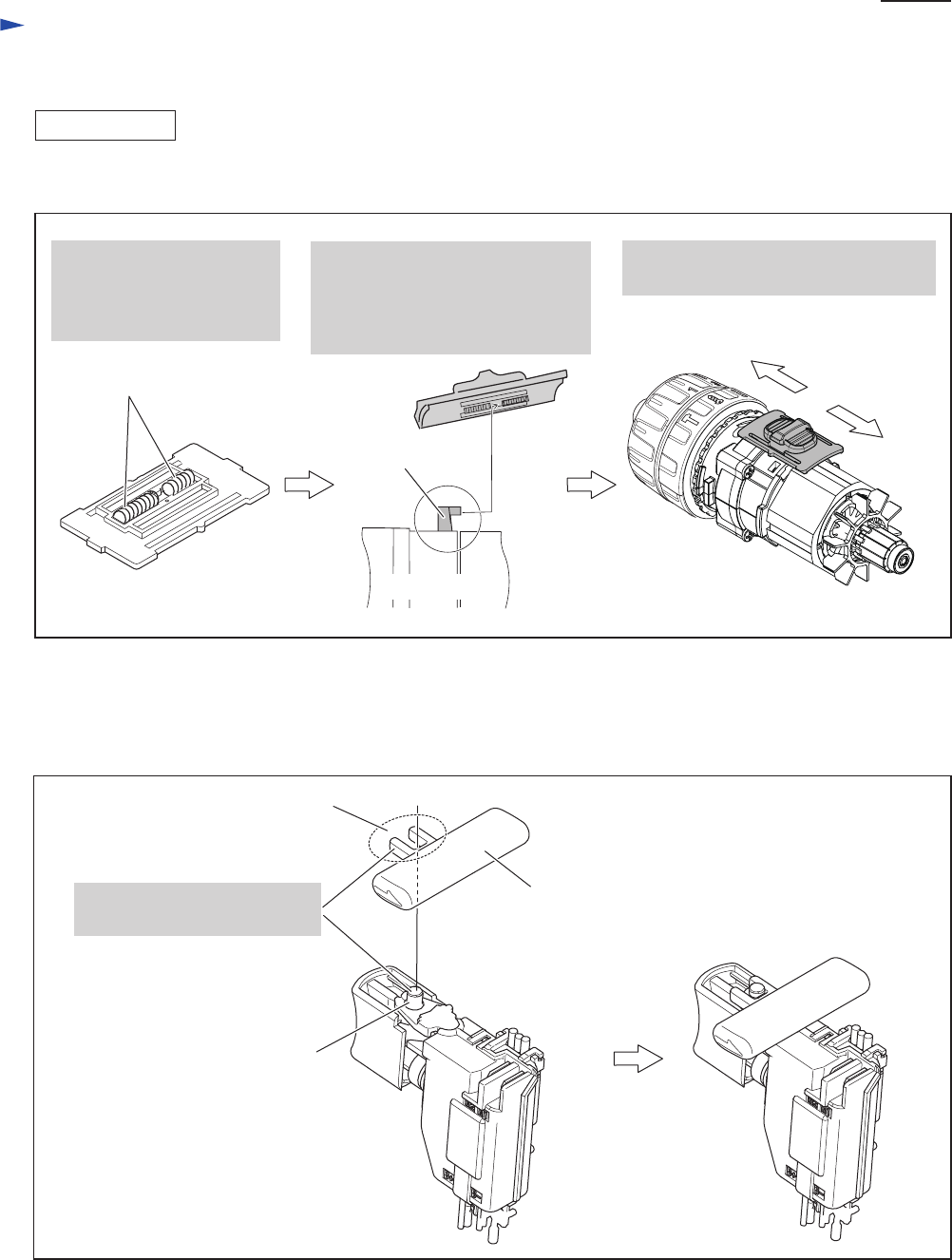
Assemble Speed change lever to Gear assembly. (Fig. 14)
Mount F/R Change lever on Switch before assembling Housing (R) to Housing (L). (Fig. 15)
Fig. 14
Fig. 15
ASSEMBLING
1. Be sure to put two
Compression springs
on the back of
Speed change lever.
hook
2. Mount Speed change lever to
Gear assembly.
Note: Be sure to fit the hook of
Gear assembly in Speed change
lever.
Gear assembly
3. Set Speed change lever to either
Low speed side or High speed side.
Low speed side
High
speed side
Compression springs
[3]-4. F/R Change lever
F/R Change lever
projection
Engage the fork portion
with the projection of Switch.
fork portion
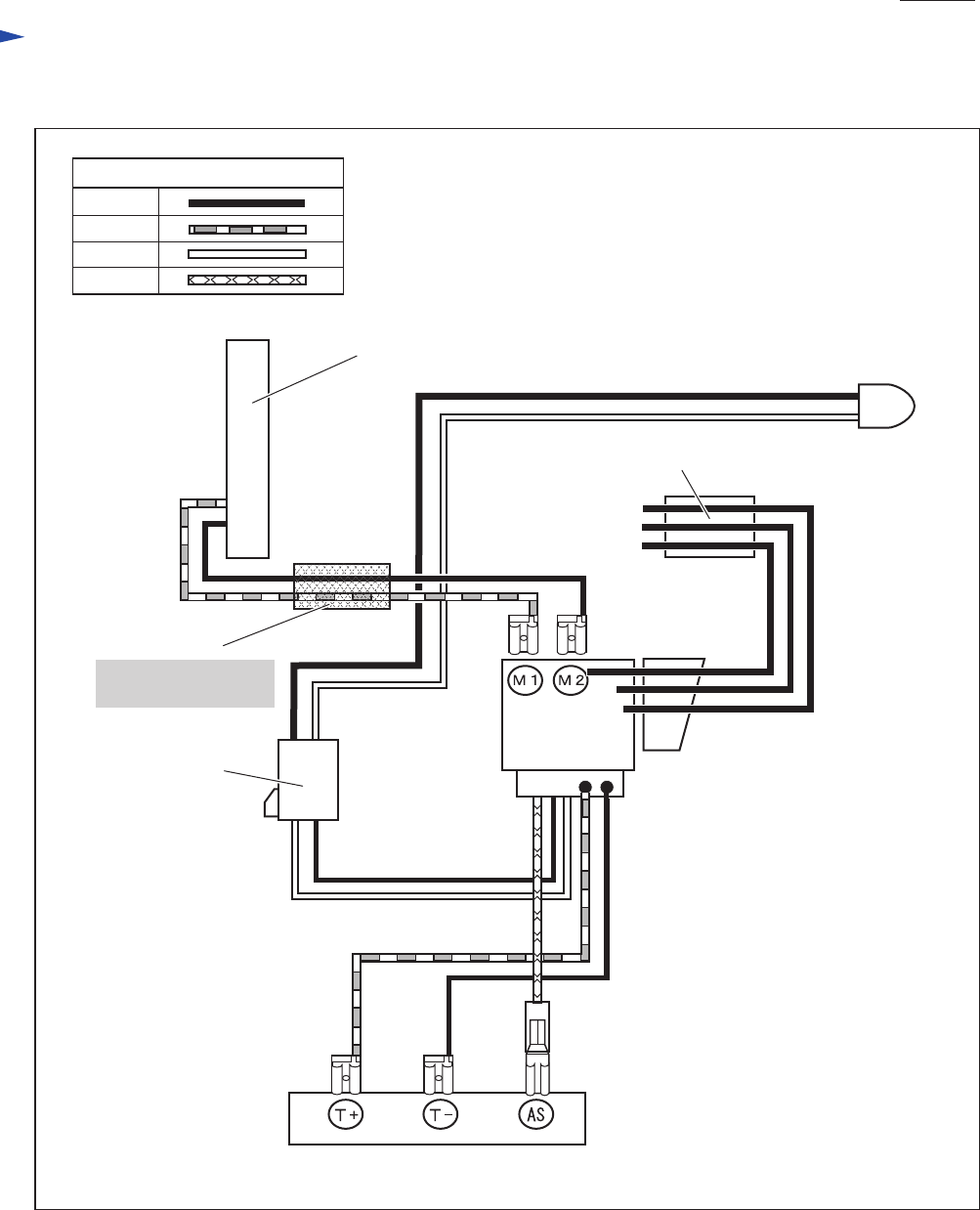
Circuit diagram
P 9/10
Fig. D-1
White
Color index of lead wires' sheath
Black
Red
Yellow
Brush holder
complete
Switch
Terminal
Connector
FET (Field effect transistor)
LED
job light
Line filter
Line filter is not used
for some countries.
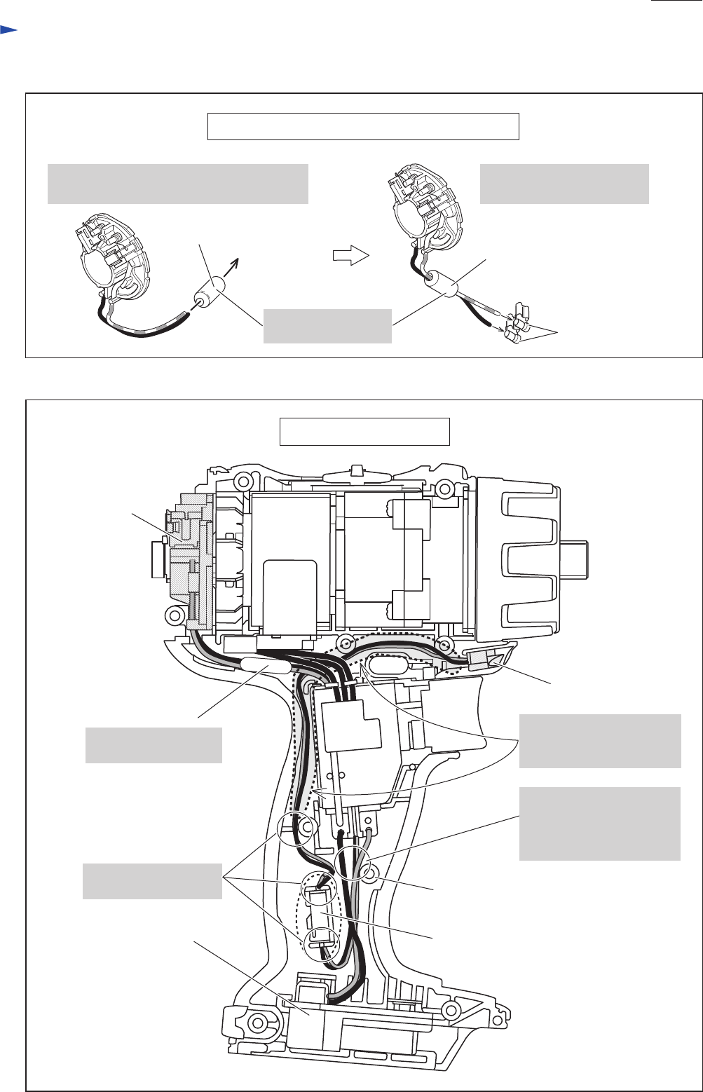
Wiring diagram
P 10/10
Fig. D-3
Fig. D-2
Brush holder
complete
Lead wire wiring of Brush holder complete
Switch
Terminal
boss
Connector
Line filter
Wiring in Grip portion
Fix Lead wires in these
Lead wire holders.
Place Line filter here
if it is used.
Line filter
2. Assemble Receptacles to
Lead wires.
1. Pass Lead wires of Brush holder complete
through Line filter if it is used.
Receptacle
Line filter
Line filter is not used
for some countries.
LED job light
LED Lead wires must be
tight in this area indicated
by the dotted line.
Pass Lead wires to Switch
in this area.
Do not pass between
the boss and Housing wall.
