Mala GeoScience SH1GHZ GPR User Manual CUII Manual A5
Mala GeoScience AB (publ) GPR CUII Manual A5
UserManual.wiki
>
Mala GeoScience
>
SH1GHZ User Manual
User manual
Navigation menu
Upload a User Manual
Namespaces
Wiki Guide
HTML
PDF
Info
Views
User Manual
Discussion / Help
Navigation

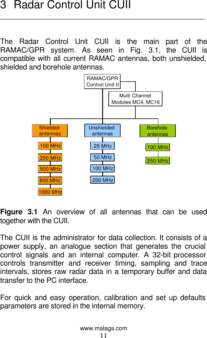
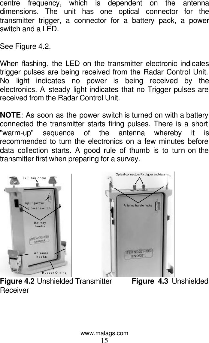
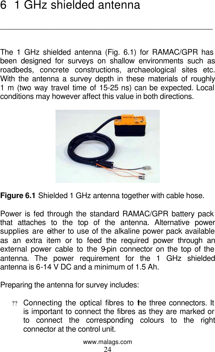
![www.malags.com 10 Table 2.2. Approximate values of ?r (relative permittivity) and the corresponding velocity. er varies greatly with the water content in the medium. The larger value given for velocity applies to unsaturated media. Medium er Velocity [m/µs] Air 1 300 Fresh water 81 33 Limestone 7 - 16 75 - 113 Granite 5 - 7 113 - 134 Schist 5 - 15 77 - 134 Concrete 4 - 10 95 - 150 Clay 4 - 16 74 - 150 Silt 9 - 23 63 - 100 Sand 4 - 30 55 - 150 Moraine 9 - 25 60 - 100 Ice 3 - 4 150 - 173 Permafrost 4 - 8 106 - 150](https://usermanual.wiki/Mala-GeoScience/SH1GHZ/User-Guide-375215-Page-10.png)