Mamiya Rb67 Pro Sd Instruction Manual
RB67 Pro-SD - Instructions Mmy_rb67_pro_sd_v7 Free User Guide for Mamiya Camera, Manual
RB67_Pro_SD_v7
2015-07-27
: Mamiya Mamiya-Rb67-Pro-Sd-Instruction-Manual-776209 mamiya-rb67-pro-sd-instruction-manual-776209 mamiya pdf
Open the PDF directly: View PDF ![]() .
.
Page Count: 43
- Cover
- Introduction
- Table of Contents
- Features
- Parts & Operation
- Specifications
- Attaching & Removing the Lens
- Waist-level Finder Operation
- Shutter Operation
- Attaching & Detaching the Roll Film Holder
- Releasing the Shutter
- Loading the Film Holder
- Operating the Revolving Adapter
- Setting the Shutter Speed & Aperture
- Focusing & Focusing Knob Fixing
- Taking Photographs
- Testing the Shutter
- Unloading the Film
- Distance Scale
- Depth-of-field
- Time exposures, Flash Photography
- Changing the Focusing Screen
- Mirror Lock-up Photography
- Multiple Exposure Photography
- Close-up Photography
- Using a tripod / Lens hood
- Carrying Strap
- Back Locking System
- Lens Mount Adapter Ring
- Operation Diagram
- Trouble Shooting
- Camera Storage & Maintenance

Congratulations on your wise decision to purchase
the Mamiya RB 67 Professional SD (Pro-SD)
The
RB67
Pro-SD is the latest addition to the long-selling
RB67
Series
which was first released in 1970. Due to its innovative 6x7cm revolving back
format, the
RB67
has been highly recognized throughout the world as the
genesis of the medium format cameras.
Specifically, the camera features an expanded
interval
lens mount diameter
(from
54mm
to
61mm,
i.e. the same as that of the
RZ67),
thereby enabling
a wider variety of new, high performance lenses, such as the APO series
to be used. The newly developed extra bright, ultra low dispersion glass
of the APO series lenses and shift lens have gone a long way to improving
system configuration.
With a wide spectrum of accessories, photographic excellence is assured
in a multitude of applications from commercial to
portraiture.
Perusing this manual before attempting to use the Pro-SD will minimize the
possibility of malfunctions.
I
6_fI
_
2pa*
and
How
,o
*pep@
.............................
3
/
@yj
m*w
SC&
...........................................
27
j
($3
1
Smifiwons ............................................
8
/
(17
/
Deoth_of_field
............................................
27
/
($0
Operating
fie
Revolving Adapter
......................
20
(24
~~~
hhng
system
...................................
36
~~leHiog_the
Shutter Speed and
lhe
Aperlure
.........
21
(-
25
Lens
Mount
Adapter
Ring
..............................
37
Ming
am)
Fmmm
bob
Fixing
...................
22
(26
Tmble
Shooting
........................................
40
(13
1
Taking
Photographs
.....................................
23
(271
Camera Storage and Maintenance
....................
41
fi4/
Testing
theShulterWhentheFilmisi.oaded
.......
261

1.
Features of the Mamiya RB67 Pro-SD
Practical
6x7cm
Since
6x7cm
format
covers
an area 4.5
times
the
35mm
format.
excellent picture quality is assured.
In
color
photography, in
particular,
it
demonstrates superior
results.
The ratio between the length and width
of
the
6X7cm
format is
almost
the
same
as that
of
large sized printing
paper, permitting economical enlargements without cropping.
The revolving adapter allows quick changeover from
the vertical or horizontal format
By
simply turning the revolving adapter
gOa,
either a vertical
or
horizontal format can be selected without moving the camera. Proper
picture composition is easily determined by index finder lines inter-
locked with the revolving adapter.
Bright, parallax-free finder
With the
lens
aperture open, the subject appearing on the large,
bright focusing screen assures speedy focusing and composing. The
parallax-free single-lens reflex Pro-SD thus is ideal for instantaneous
photos where the utmost in quality is required.
The Pro-SD roll film holders assure excellent film flatness
The Pro-SD roll film holders are designed with the utmost consider-
ation given to film flatness and also feature an interlocked multiple expo-
sure
prevention
system.
The newly designed dark slide slot accepts the dark slide from either
the
left
or
right side.
The
6x8 cm
format now possible
The Pro-SD body back is designed to permit
6x8cm
photography,
thus expanding the photographic scope
for
studio work and in other
fields that use
6x8cm.
Close-up photography through the full
use
of the
bellows
Since the
bellows can be extended up to 46mm photographing even
the smallest subjects in frame full is possible. When auto extension
tubes are used, the
subject
can
be
further enlarged. When a standard
lens is employed, life-sized
(1:1)
reproductions are possible
only
with
the tubes.
Excellent heat and cold resistance
The Pro-SD is mechanically advanced
so
that is components can
function over a wide temperature range from approximately -20°C
to
-50°C.
Enlarged lens mount
Compared
to
the
convetional
RB67
Series, the
Pro-SD
has a
lens
mount with a diameter 7mm larger. making it possible to accept a new
group of high performance sophisticated lenses, such as the APO, shift,
and newly designed wide angle
lens
75mm. Since the lenses are
systematized, a
lens
suitable for desired composition can
be
selected.
The new lenses are designed with emphasis on color contribution and
feature a built-in bulb
(B)
unit, and the wide-angle lenses
have
a float-
ing feature to assure improved close-up performance. All
Pro-SD
lenses
use
a lens shutter and an electronic flash synchronize for all
shutter
speeds.
Extensive
variety of accessories and interchangeable
film holders
Pro-SD accessories are interchangeable with those of the
RB67
Series and are available in a diverse
variety,
thus
satisfying
every
possible
photographic need
A wide
variety
of film holders are
avaialble:
6x7cm
format 120/200
roll film holders and
6x4.5cm
(semi-format) holders for the Pro-SD,
as
well as 6x7cm and
6x8cm
power
drive
holders,
70mm
holder and
sheet film holders. All these assure high quality, sharp images
over
a
large picture area.
2
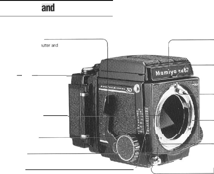
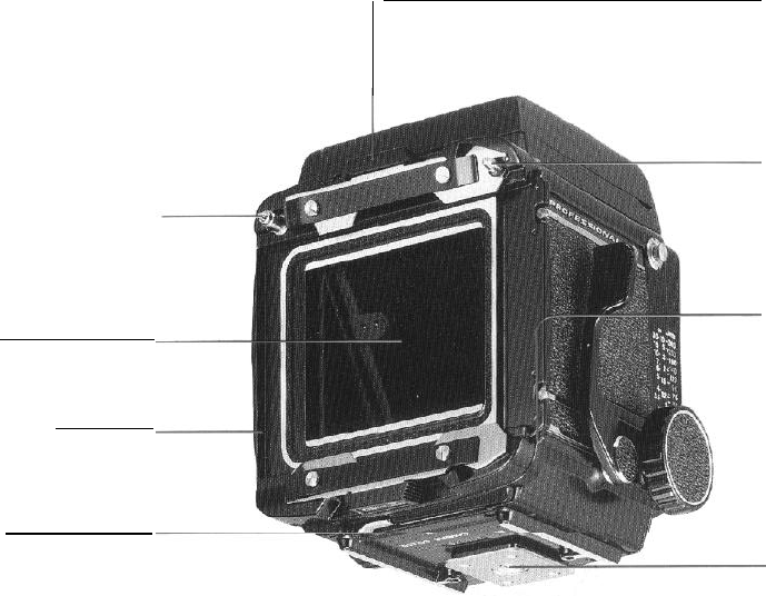
2. Parts
andand
How
to
Operate
Shutter cocking lever
The lever cocks both the sh
the mirror. Unless they are set,
a
safety device prevents the shutter
release button from being depressed.
Dark slide
-
-
When the dark slide is inserted, a
safety device prevents the shutter
release
button
from being depressed.
(Take the dark slide out before taking
a picture and put it into the storing
lug.)
Mirror (Never touch it!)
Distance graduation
Focusing knob
Nameplate
By
sliding the nameplate, the focusing
hood can be exchanged.
. Finder latch
The latch prevents the finder
from
slip-
ping off if the nameplate is carelessly
move.
Lens mounting index mark
(red dot)
Lens mount
Shutter release button
A
safety device will prevent the shutter
from being released if the camera
is
not completely ready for photography.
Distance scale
L
Shutter release lock ring
When index mark of the ring is aligned
with the red dot, a safety device
pre-
vents
the shutter release
button
from
being depressed. (Align the index
mark with
the
white dot before taking a
picture.)
3
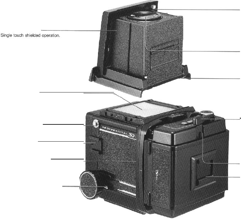
Waist-level finder
Focusing screen
Various interchangeable screens are
available. Being interlocked with the
revolving
adapter, horizontal picture
format
index lines appear under the
screen.
Carrying strap lug
Accessory shoe
Dark slide storing lug
Insert
the dark slide of a holder without
a dark
slide
slot.
Focusing knob fixing lever
-
Magnifier setting lever
By moving the lever to the left, the
magnifier can be set. By pressing
down on the magnifier base plate, the
magnifier can be hooked in place.
Diopter
lens
The diopter lens is interchangeable
with other diopter lenses.
Finder mounting prongs
-
Film advance lever
Unless the film is loaded and
advanced, a multiple-exposure pre-
ventive device pevents the shutter from
being released. Unless the shutter is
released, the film cannot be advanced,
thus preventing idle film advance.
Film wind-stop release lever
-Memo clip
Convenient slot to store
covers or to enter other dat
film box
a.
4
Coupling pin for film wind-stop
release
When the shutter is released, the pin
will automatically disengage film
wind-
stop
allowing
subsequent film advance.
Light baffle
DO NOT touch the baffle with your
fingers!
Revolving adapter
Turning this adapter up to 90°
permits
change-over between the horizontal
and vertical picture format.
R-lock lever
Use the lever to attach and detach the
revolving adapter.
-Slide lock for G-lock type
holder
Use the lock to attach and detach film
holders. When the dark slide is not
inserted in the attached roll film holder,
a safety device prevents the holder
from being detached from the camera
body.
Coupling pin for multi-exposure
prevention
Release lever for slide lock
When detaching a film holder other
than the roll film holder, or when the
slide lock
is
locked, move the slide lock
to the left while pressing this release
lever.
Tripod socket
The socket fits
to
a U
1/4-inch
tripod
screw. By
removing
the inner socket, a
tripod with a 3/8-inch tripod screw can
be used.
5
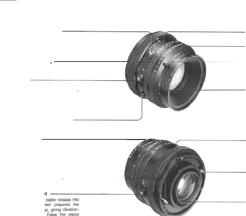
Synchroflash terminal
(X contact)
Synchronized at all speeds.
Shutter speed
ring
Bulb (B)
Used to close the shutter when the
shutter speed
dial has been set at
T (time).
Depth-of-field preview lever
d
Bayonet ring
The bayonet ring clamps the lens to
the body. When the mirror is not
cocked, a safety device prevents the
lens from being removed.
Cocking positionmarks
Mirror-up
socket
Merely
screwing a
the mirror-up
soc
camera for mirror-u
free photography.
before-hand, then release the shutter
just when taking a picture.
6
Aperture scale ring
Depth-of-field scale
Distance scale for depth-of-field
reading
The
ring is calibrated in both meters (m)
and feet
(ft).
Distance scale lever for
depth-
of-field reading
Shutter release lock pin
The
shutter
can be released by turning
the
shutter
cocking pin clockwise while
pressing the lock pin.
Shutter cocking pin
When cocking the
shutter
with a finger,
turn the cocking pin to the red dot.
Lens mount adapter ring
By
removing the KL lens adapter ring,
use it with the
RB
series lens body.
(When using with the Pro-SD, attach
the adapter ring to its original position.)
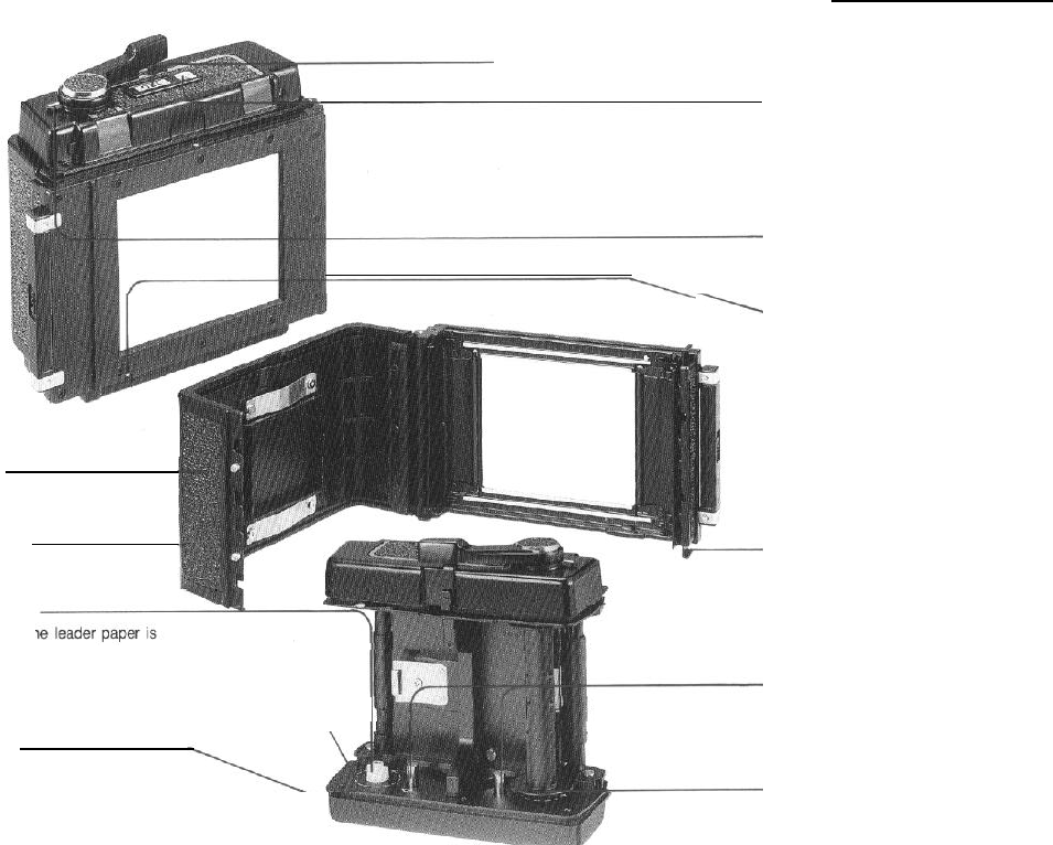
Film type index (120 or
220)
Pro-SD Outer
cassette
Back cover
Dark slide slot
Accepts
the dark slide from either the
right
or left side.
Film spool stud
Load film so that th
pulled out following the guide marks.
Guide mark for leader paper
___________________
Starting mark
Wind the film advance lever until the
leader paper staring mark is aligned
with this mark. After closing the
back
cover, wind the lever several
strokes,
and it will stop at the first
exposure
Exposure counter
When the film is advanced and the
shutter is released,
a
red mark appears
on the side of the counter digits. When
the next film advance is completed,
the red mark disappears. The red mark
also appears while the film is being
advanced from S to 1
.
Multiple exposure lever
When multiple exposures are desired,
simply
move
this lever to the front until
the red mark becomes visible.
Safety-catch for dark slide
When the film holder is being carried
about after detaching it from the
camera body, the safety device pre-
vents the dark slide from accidentally
slipping off.
When the
film
holder is attached to
the camera body, the dark slide can be
removed automatically.
Back cover latch
(top and bottom)
To open back cover, both top and
bottom latches must be pulled out.
Spool release pin
The film spool is attached and
detached by pressing down this pin.
Take-up
spool stud
After
inserting the take-up
spool,
the
leader paper is inserted in the spool.
position.
7
l
Camera Body
Type:
6x7cm
lens-shutter single-lens reflex
camera: corresponding the
6x8cm
format.
Lens
mount:
With safety lock ring.
Viewfinder:
Horizontal format index mark interlocks with
revolution of revolving adapter (Vertical for-
mat based on fixing index line on focusing
screen) 96% of the field of view visible.
Waist-level finder:
Single-action opening and closing, with
mounting lock.
Interchangeable.
Finder magnification is 3x. Interchangeable,
diopter lens.
Focusing screen:
With fresnel lens. Interchangeable. (7 types)
Revolving adapter
Full 90° revolving rotary system; vertical
horizontal format indicator interlocking
mechanism.
By R-lock interchangeable system with
Polaroid pack film holder, etc.
By G-lock revolving adapter system,
G-
lock-type film holders are attachable.
Focusing:
Bellows extension system with rack and
pinions.
Maximum extension 46mm. With focusing
knob fixing device.
Shutter and mirror cocking:
Single-action (75°) cocking by lever on the
side of the body.
Additional
features:
Accessory shoe is provided.
Shutter release button can be locked to
prevent releasing the shutter accidentally.
l Standard Lenses:
Lens:
Mamiya KL 127mm
f/3.5L
with lens hood
Composition:
6
elements in 4 groups
Angle of view:
38°
Filter screw diameter:
77mm
Aperture:
Full automatic diaphragm (with
depth-of-
field preview lever). f/3.5 to 32 (with
click-
stops for aperture settings).
Shutter:
Seiko
#1
shutter
1 to
1/400
second and T (Time)
Flash
synchronization:
X contact
Other features:
Mirror-up photography. Bulb (B) feature.
l
Pro-SD 120 Roll Film Holder
Film used:
120 roll film 10 exposures;
6x7cm
format
Actual negative size: 56x69.5mm
Film advance:
One-stroke film advance lever (After winding
70°
can be wound in several short, definite
strokes).
Automatic multiple-exposure prevention.
Film wind-stop automatic release.
Multiple exposures are also an option.
Film counter:
Automatic reset; red index mark disappears
upon completion of film winding
Features dark slide
dislocation
prevention,
storing lug and memo clip.
l
Dimensions:
(Camera body with roll film holder)
Height: 144mm
Width: 104mm
Length: 233mm (with 127mm f/3.5 lens)
l
Weight:
Camera
body
. . . . . . . . . . . . . . . . . . . . . . . . . . . .
1050g
Revolving adapter
.~....,.,....,....................
200g
Waist-level finder
. . . . . . . . . . .
.._...................
185g
Pro-SD roll film holder . . .
.._...._......_._.......
475g
KL
127mm
f/3.5L
lens
.._...._......_._...._..
780g
Totalweight
. . . . . . . .
2690g
8
4.
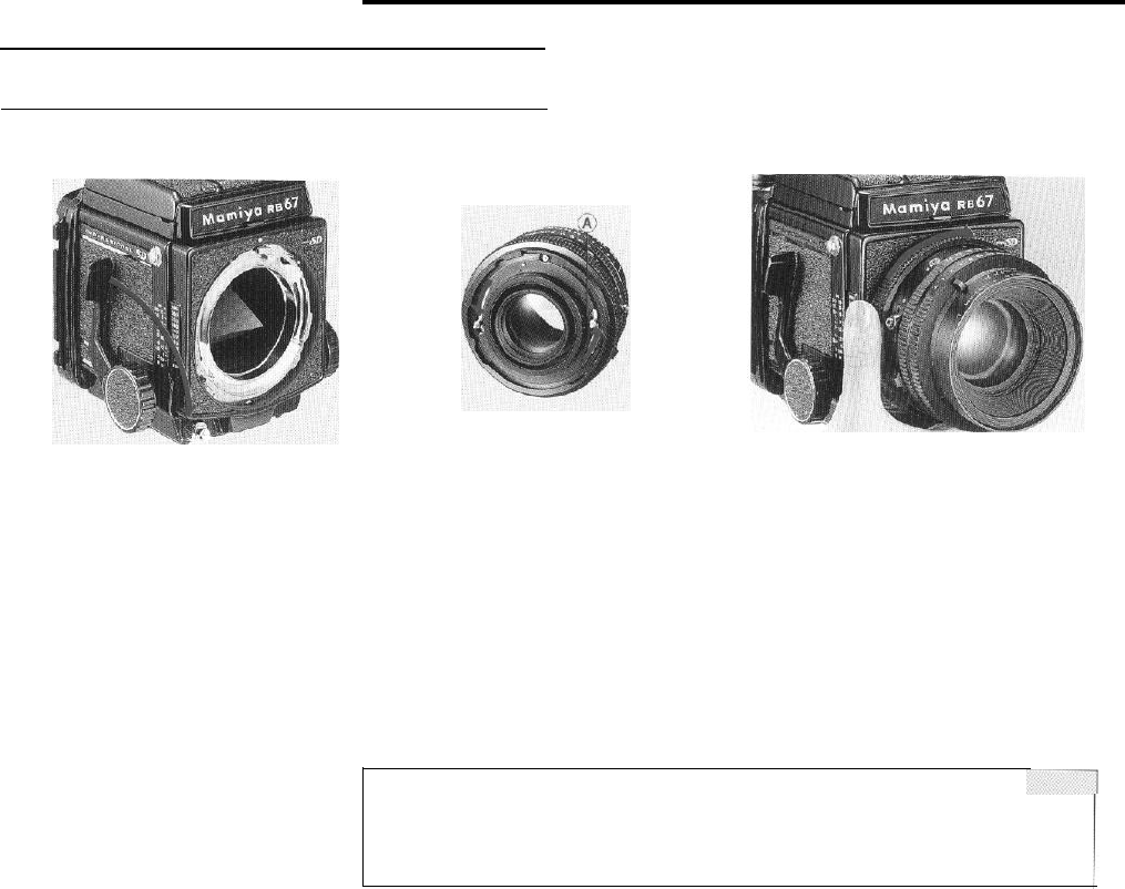
Attaching and Removing the Lens
After cocking the mirror and the lens
shutter, mount the lens on the camera body.
Cocking the mirror
1. Remove the front body cap from the
camera body.
2. Be
sure
that the mirror is in the cocked,
down position in the camera body, shielding
the film plane from exposure to light.
If the mirror is up, cock the mirror by fully
pushing down the shutter cocking lever toward
the front of the camera.
Cocking the lens shutter
1. Remove the rear cap of the lens by turning
the bayonet ring clockwise.
2. Cock the lens shutter. Firmly turn the shut-
ter cocking pins with your fingers, to the red
dots (A) of the cocking position,
l
If the cocking pins are not fully turned to the
red dots (A), the shutter will not be com-
pletely cocked.
l
The shutter is always cocked on a lens that
has been removed from the body.
Attaching the lens
1. Turn the bayonet ring counterclockwise,
and align the white dot on the bayonet ring
with the red mark at the center of the lens
mount.
2. Mount the lens, keeping the red mark
aligned with the red mark on the body; then
firmly
twist
the bayonet ring clockwise. The
camera and lens are now set.
NOTE:
Do not place the camera on its back
without
the rear body cap or film holder being in place.
Otherwise the coupling mechanism may be damaged!
.
9
Removing the lens
1. Set the mirror and cock the shutter by
pushing the cocking lever as far as it will go
toward the front of the camera body.
2.
Rotate the bayonet ring of the lens counter-
clockwise as far as it will go (the white dot on
the bayonet
ring
will align with the central red
mark on the body) and remove the lens.
l If the mirror and the shutter are not cocked
the safety interlock will interfere with the
rotation of the bayonet ring and the lens
cannot be removed.
..,
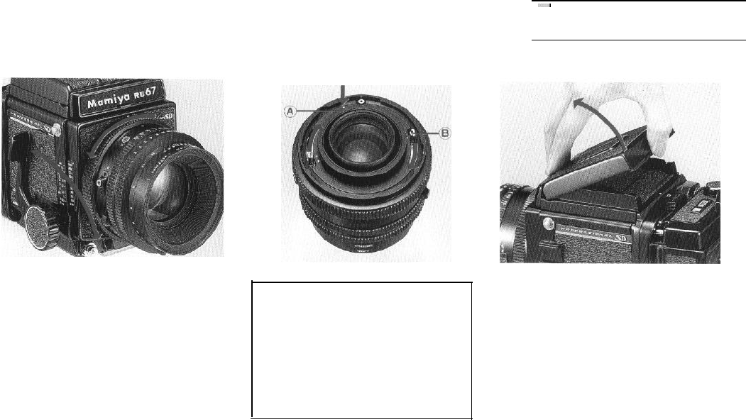
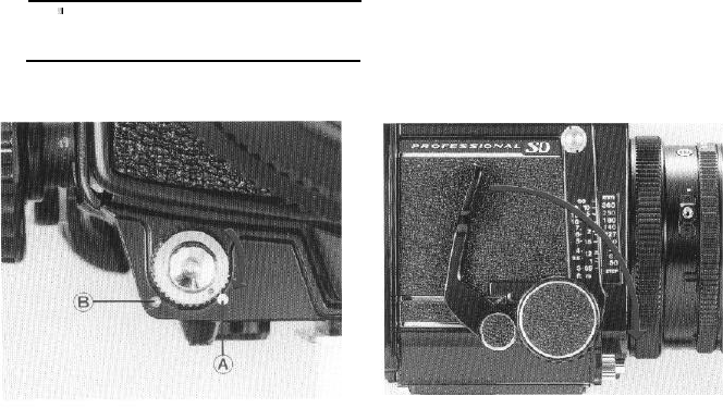
5.
Waist-level Finder
Releasing the shutter on a lens which
has
been
removed from the body
To release the shutter on a lens which
has been removed from the camera body,
turn the cocking pins
(B)
clockwise, while
pressing the shutter lock pin (A) with a
finger. The cocking pins should be turned
all the way; do NOT leave the pins turned
halfway.
Raising the flnder
Merely lift the back of the finder until it
opens completely.
1010
Operation
Raising the magnifier Lowering the magnifier
Slide the magnifier release slightly to the left
Gently push the base plate of the magnifier
and the magnifier will pop up into position. all the way down until it locks in place.
Folding the finder
After lowering the magnifier, gently squeeze
the right and left panels of the finder together
while closing it.
11
Changing the diopter lens
While holding the diopter lens base plate
with both side panels of the finder, turn the
diopter lens counterclockwise, and at the point
where the white dot on the diopter lens aligns
with the white dot on the base plate, remove
the diopter lens.
To mount another diopter lens, simply
aligns its white dot with that of the base plate
and turn clockwise.
l In addition to the standard (-1.5) diopter
lens, there are 5 others: +1
,
0,
-1,
-2,
and -3.
Detaching the finder
While pressing the finder latch (A), as viewed
from the front, slide the nameplate to the right,
and while slightly raising the front remove
the finder.
Attaching the finder
Insert the two prongs on the back of the
finder into the slots on the camera body, and
while pressing the front portion of the finder
toward the camera body, return the nameplate
to its original position. The latch will pop out
and the finder will lock automatically.
12
,:
6.
Shutter Operation
Shutter release button
The shutter release button incorporates a
safety mechanism to prevent accidental release
of the shutter.
When the shutter release locking ring is
turned and the red index dot is aligned with the
white dot (A) on the body, the shutter release
button can be pressed.
When the red index dot is aligned with the
red dot
(B)
on the body, the shutter release
button
cannot be pressed.
Releasing the shutter
When the shutter release button is pressed,
the mirror is pushed up and the shutter is
released.
l If the mirror is not cocked, the shutter
release button cannot be depressed.
. The socket inside the shutter release
button
is threaded so that a cable release or a
self-
timer can be easily attached.
13
Cocking the shutter
Push the shutter cocking lever forward until
it stops. The shutter in the mounted lens and
the mirror in the camera body will be cocked
simultaneously. The lever will return to its
original position automatically.
l When the shutter is not completely cocked
the shutter cocking lever will not return to its
original position.
. Once the shutter is cocked, the cocking
lever will not move until the shutter release
button is pushed and the shutter released.
Therefore, when the cocking lever
does
not
move, it indicates the shutter is cocked.
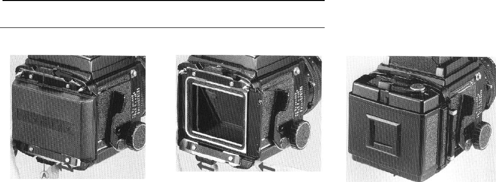
7.
Attaching and Detaching the
Roll
Film Holder
Removing the rear body cap
By moving the slide locks (A) on both sides
all the way to the left, the cap be removed.
l Never push the light baffle on the camera
back after removing the rear body cap. If
the light baffle is forced, light leakage or
other malfunctions may occur.
Attaching the roll film holder
1.
Slide the upper and lower slide locks (A) on
the back the body completely to the left of the
indentation.
NOTE:
Should either slide lock be moved to the
right while nothing is attached to the
revolving adapter, the slide lock release
lever (B) will engaged and the slide lock
will not move. If this happens, press the
release lever (B) and
return
the slide lock
to the open position.
14
2.
Attach the
roll film holder to the body and
slide both slide locks firmly in the direction of
the arrow. (lock)
l If the revolving adapter slide lock is not
completely pushed in or pulled out, the
shutter safety lock will not release the shut-
ter. Always make sure the slide lock is
properly engaged or disengaged.
l The shutter release button can not be
depressed if the dark slide is completely
inserted or if here is no film in the camera.
In addition the Pro-SD roll film coupler pre-
vents multiple exposures. (See pages 16
and 25 for the shutter release test.)
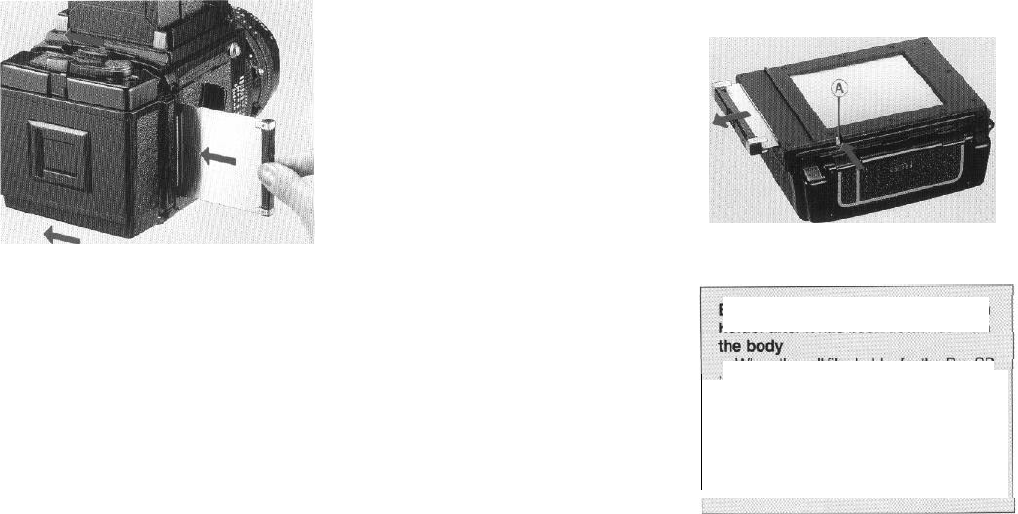
Removing the roll film holder
1. Insert a dark slide in the roll film holder.
2. Remove the roll film holder by sliding both
slide
locks
in the opposite direction to the arrow
(Lock) on the slide lock.
.
If the dark slide is not inserted, the slide lock
will be locked by the safety device, and the
roll film holder cannot be detached.
l When a dark slide is completely inserted,
the slide lock release lever is automatically
disengaged, and the slide locks can be
moved without pressing the release levers.
Extracting
the
dark slide of the roll
film
holder after it has
been
detached
from
When the
roll
film holder for the Pro-SD
is removed from the body, the safety
device prevents the dark slide from being
pulled out carelessly or accidentally.
However, if you desire to pull it out, simply
use your fingernail tip to press the dark
slide lock release lever (A) on the bottom
of the outer cassette.
15
8.
Releasing the Shutter
It is best to become aquainted with the
method of releasing the shutter before
actually putting film in the camera.
1.
Rotate
the shutter release lock ring until
the mark on it is aligned with the white
dot on the body.
2.Remove the dark slide or pull it out until
all the triangular holes become visible.
3.Push the multiple exposure lever on the
roll film holder forward to the multiple
exposure position
-
i.e. until the red
mark is visible.
4.
Push the cocking lever all the way down.
5.
Press the shutter release button.
The
first
steps can be done in any order. After
you are thoroughly familiar with the above
steps, return the multiple exposure lever to its
normal setting.
16
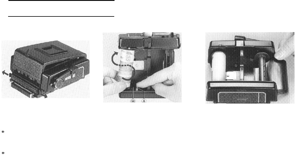
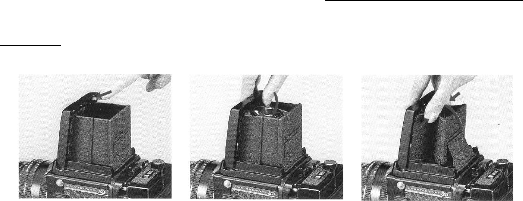
9. Loading the Film Holder
1. While pressing the back cover, pull out the
upper and lower back cover latches and the
back cover will open. Remove the film insert.
When loading film, avoid direct sunlight:
either load the film in the shade or turn your
body away from the sun and load it in the
shade of your own body.
Use 120 roll film with the 120 roll film holder
and 220 roll film with the 220 roll film holder.
2. While pressing the spool release pin (A) on
the left side of the film insert, insert a new roll
of film on the film spool stud.
Load the film so that the leader paper can
be pulled out along the arrow of the leader
paper guide mark (B). Wind the
film
with the
printed side of the leader paper on the holder’s
pressure plate side. If the printed side does
not lace the pressure plate side, reload the
film, reversing the film position.
3. Pull out the leader
paper
and insert the tip
into the groove of the take-up spool.
*
Position the film so that
the
leader paper
winds evenly between the spool flanges-if it
is uneven, film and photo malfunctions may
occur.
17
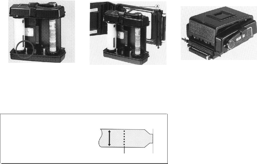
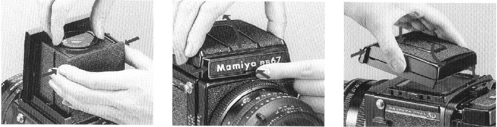
Move the film advance lever gently, until the
starting mark (arrow) of the leader paper aligns
with the starting mark of the holder. The film
advance lever can be moved in several short,
definite strokes.
l If the leader paper is pulled too far, the film
may become fogged, so be careful not to
go beyond the arrow.
1.
Put the insert into the cassette, aligning the
top side of the insert with the white dot (A) of
the cassette.
l If the film insert is attached in reverse, the
back cover cannot be closed.
Setting Start Mark with 220 Roll Film
. To assure even frame spacing, and
prevent overlapping, be sure to wind the
film up to the printed arrow start mark,
which appears after the dotted line.
ifi>
DO NOT use the dotted line for a start mark.
18
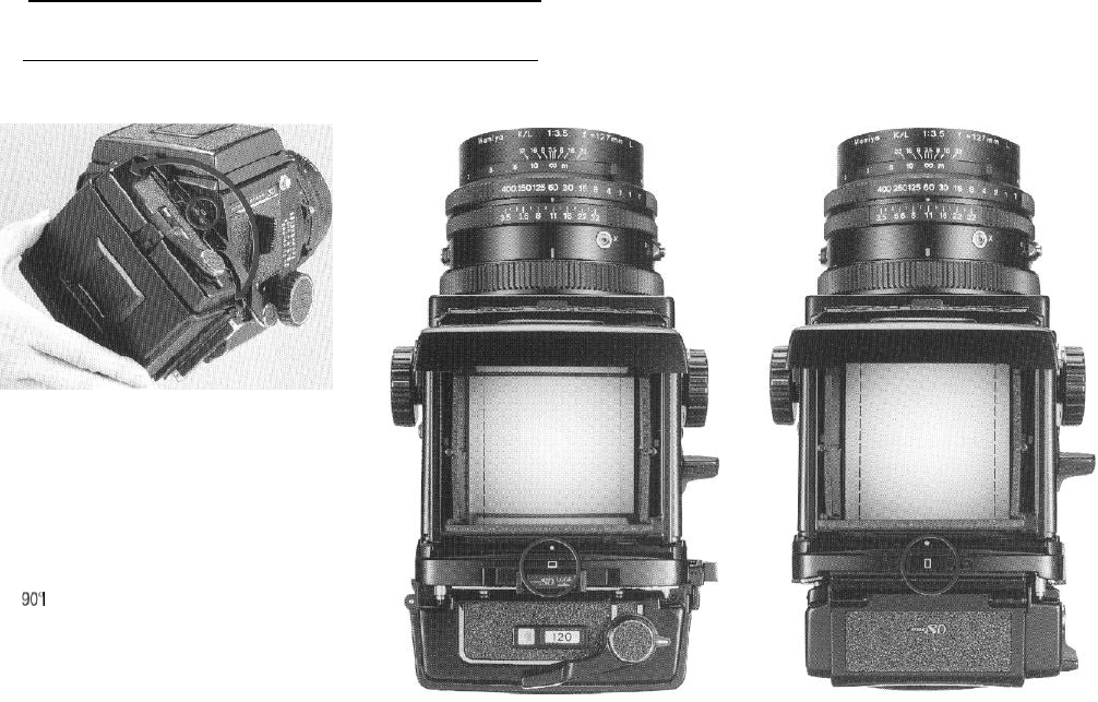
2. While pressing the back cover gently, push
the back cover latches (top and bottom) as far
as they will
go,
NOTE:
1. The
outer
cassette of the Pro-SD roll film
holder (HA-701) can be used for both
120 and 220 film inserts.
2. The film insert of the Pro-SD roll film
holder cannot to
be
attached to the outer
cassette of the Pro-S roll film holder.
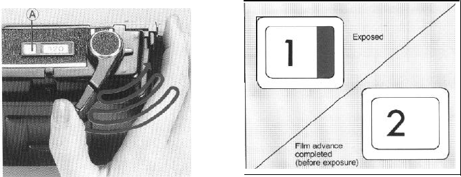
Exposure Counter
Film winding for first exposure
When the film is completely advanced, the
numeral ‘1’
will
appear in the exposure
counter and the red film-advance warning will
disappear indicating that the holder is ready
for photography.
l The shutter cannot be released unless the
film from S
(start)
to 1 has been completely
advanced with the cocking lever.
1919
1 0.
Operating the Revolving Adapter
Operating the revolving adapter
When the horizontal format mark of the
revolving adapter is facing upward, a horizontal
photo will result. For a vertical photograph, turn
the revolving adapter clockwise until it stops.
To change from vertical to horizontal, turn the
revolving adapter counterclockwise.
In either case, be sure to turn the adapter a
full until it clicks and stops. If the adapter is
stopped midway, the shutter release button
cannot be pressed.
l Do NOT turn the revolving adapter while
the shutter release button is being pressed.
Especially, when a cable release or a
self-
timer is used, and adjustment of the release
tip is improper, the shutter release button
will remain depressed after the shutter is
released. Please note!
(Changing the Picture Format to Horizontal or Vertical)
Horizontal picture format
When the revolving adapter is positioned for
horizontal format photos, the solid red lines on
the ground glass focusing screen indicate the
limits of photo composition.
20
Vertical picture format
When the revolving adapter is positioned for
vertical format photos, the broken red lines on
the ground glass focusing screen indicate the
limits of photo composition.
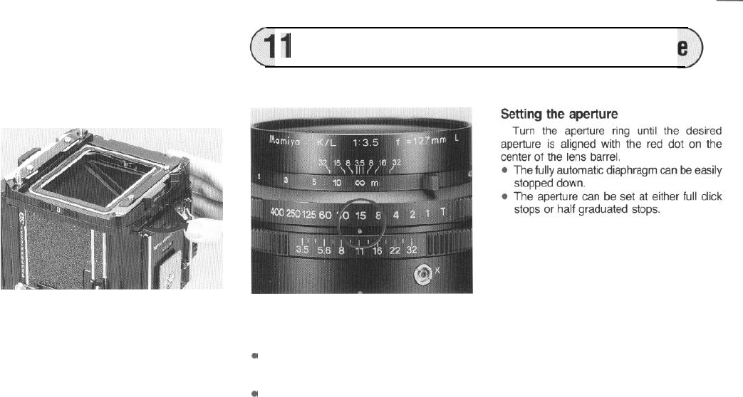
1
1
Setting the Shutter Speed and the
Apertur
Removing/attaching the revolving
adapter
To remove the revolving adapter, pull down
the R-lock lever (A) on the back bottom of the
camera.
To attach the revolving adapter, position the
white dot on the side of the adapter towards
the upper side of the camera, and completly
push in the R-lock lever while firmly holding
the adapter to the camera body.
l The revolving adapter for the Pro-S can
also be used.
l When attaching the revolving adapter,
securely hold it to the camera body.
A loose attachment may cause incorrect
focusing or leakage of light.
Setting the shutter speed
Align the desired shutter speed with the red
dot on the center of the lens barrel.
.
.
Always set the shutter speed to the click
stop position: intermediate shutter speeds
cannot be used.
If the speed is changed, after cocking the
shutter, do not turn the shutter speed ring
rapidly.
21
12.Focusing and Focusing Knob Fixing
Focusing
When the shutter is cocked, the mirror is
cocked simultaneously, and an image is visible
on
the ground glass focusing screen. By
turn-
ing either the left or right focusing knob, adjust
the focus and compose the picture.
Focusing knob fixing
After adjusting the focus, turn the focusing
knob fixing lever forward and clamp it to secure
the focusing mechanism.
l Once secured deviations in focusing are
prevented-ideal for conditions of continuous
photo taking.
22
1
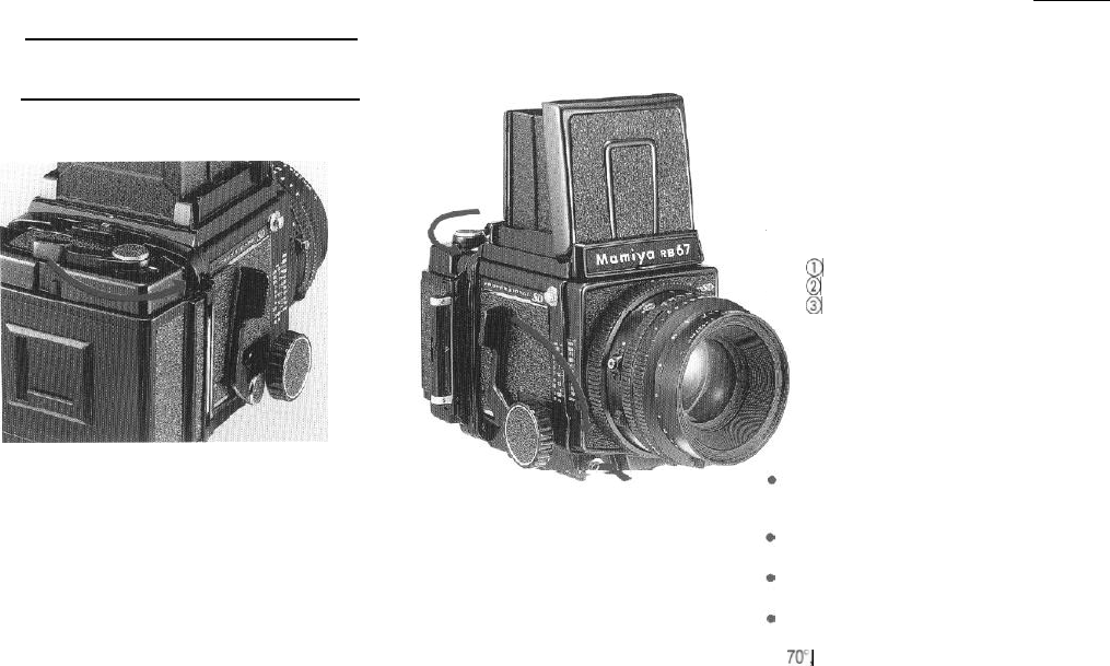
3. Taking Photographs
first.
Advancing the film
1. Take out the dark slide and release the
shutter. When the shutter is released, the
red
mark will appear in the exposure counter indi-
cating that the film has been exposed.
2. As the shutter is released, simultaneously
the film wind-stop mechanism is automatically
disengaged, and the film can be advanced to
the next frame. When film is advanced one full
frame, the figure in the exposure counter
advances and the red mark will disappear.
Advancing the film and cocking
the shutter
@
Film
advancing
@
Shutter cocking
@
Shutter releasing
However,
either advancing the film or
cocking the shutter can be conducted
The multiple-exposure coupler will prevent
shutter release unless the exposed film
frame is advanced.
A multiple-exposure photographic mode is
an added feature.
Wind the film advance lever in a slow, steady
manner to avoid film advance problems.
Although the film advance lever cannot be
reversed until it is wound up to the initial
70’,
it can be moved in several short, definite
strokes thereafter.
23
Storing the dark slide
When photographing, the dark slide may be
conveniently kept in the storage on the back of
the holder. It can be inserted either from the
right or
left
side.
The dark slide can also be stored on the
side of the camera body as pictured.
Memo clip
The clip on the back cover can be used for
holding the cover of a film box or a slip of
paper to record photographic data.
24
14.
Testing the Shutter When the Film is Loaded
When the shutter is cocked with the
darkslide
partially pulled out
(approx. 5mm)
and the shutter release button is pres-
sed, the shutter can be released without
exposing the film in the roll film holder to
light. This operation can be utilized for
testing the shutter prior to photographing.
When pulling out the dark slide, stop
when the entire triangular hole on the
dark slide becomes visible. If the shutter
is
released when the dark slide is pulled
out beyond that hole, the film will be
exposed to light.
When the shutter is released, a red mark
will appear on the exposure counter.
When taking the first photograph sub-
sequent to this test, cock the shutter in
the multiple exposure mode (see page
32),
and pull out the dark slide. After the
first photo is taken, move the multiple
exposure lever back to its normal posi-
tion and continue photographing.
25
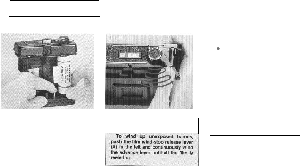
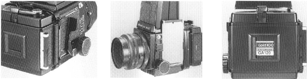
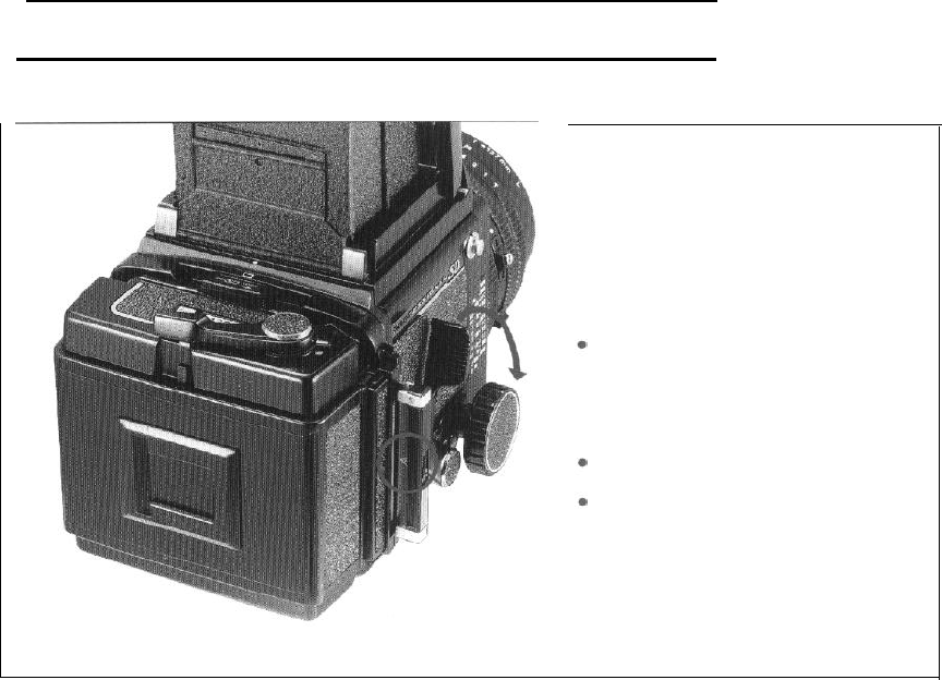
15. Unloading the Film
After completing the last exposure,
completely wind the backing paper on to
the take-up spool.
1. Open the back cover of the holder and
remove the film insert. Press the right side
spool release pin, remove the full spool, then
wrap and seal the film to protect it from loosen-
ing.
2. Move the empty spool to the take-up side
and the camera is ready for reloading.
l The exposure counter automatically resets
to S (start) as soon as the back cover is
opened.
l When the exposure counter shows other
than S, film is in the holder. Be careful not
to
open the back cover in this mode!
Winding up film when unexposed
frames remained in the holder
Handling of Exposed Film
0
DO NOT remove exposed film from
the camera unde direct sunlight. Find
a shaded area or turn your back to
the sun and shade the camera before
you open it.
l
When removing the exposed film,
be
careful to prevent it from unraveling
on the
spool.
Gently tighten the paper
trailer, moisten the attached seal, and
secure the film to prevent light leaks.
l Immediately place exposed film in
your camera case or a bag, away
from sunlight.
26
.
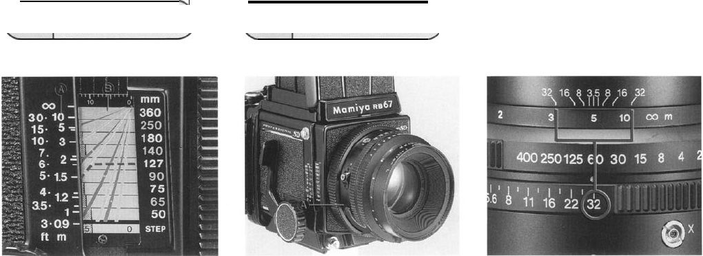
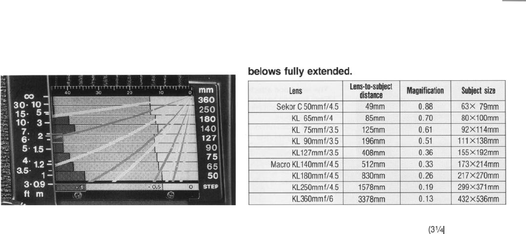
16. Distance Scale 17. Depth-of-field
Distance from the film plane to the subject
can be determined by the distance scale (A).
Each lens features different distance scale
curves as pictured above. The figure on the
distance graduation
(B)
which align with the
curve indicates the distance to the subject.
For example, if the distance graduation and
the curve are as shown in the photo after
focusing with the 127mm lens, distance to the
subject is
1.5m
(5ft).
The focusing screen
1. Set the desired aperture by turning the
aperture scale ring and then adjust the focus.
2. Depress the depth-of-field preview lever
(A) and the depth-of-field can be observed on
the ground glass focusing screen.
Upon removing your finger, the lever will
return to its original position and the lens aper-
ture will fully reopen.
The curve for each lens is marked with a
white dot. Since the dot coincides with the
right-hand lens indicator, use it to quickly find
the curve on the scale for the lens used.
Using the depth-of-field scale
1. Turn the distance scale lever and align
the figure representing the focused distance
with the center index on the depth of field
scale.
2. The two distances (on both sides of the
center index) opposite the same figures as the
actual lens aperture on the depth-of-field scale
are the near and far limits of depth for a given
distance and lens aperture.
For example, when photographing a subject
5 meters away with the
127mm
lens at an
aperture of f/32, objects from about 3 to 13m
will be in focus.
27
18.
Time (T) exposures, Flash
Photography
To make a time exposure, first set the
shutter speed
ring
to T and screw a cable
release into the bulb socket. After doing so,
the shutter will remain open upon depressing
the shuner release button.
The shutter will be closed by pressing the
plunger of the cable release without giving any
shock to the camera.
The shutter can also be closed by following
procedures.
1. depressing the bulb socket by finger
2. turning the shutter speed ring toward 1 sec. When the shutter is closed by the shutter
(1)
cocking lever, the lever is locked by the
3. pressing down on the shutter cocking lever
reverse motion stopper and does not return
about 30° to its original position. When the shutter is
cocked by further depressing the lever, the
l Do not move the shutter cocking lever until
just before closing the shutter.
l When the shutter is closed by the shutter
cocking lever, the light baffle in the camera
body drops down slightly; however no fog-
ging occurs,
lever returns to its original position.
28
Flash photography
Connect the cord of the flash unit to the
synchroflash
terminal (X contact).
. The flash unit synchronizes at all shutter
speeds.
Determining the aperture
The aperture
setting
for flash photography
is determined by dividing the guide number of
the flash unit by the subject distance.
For example, when photographed with
IS0100 in m.
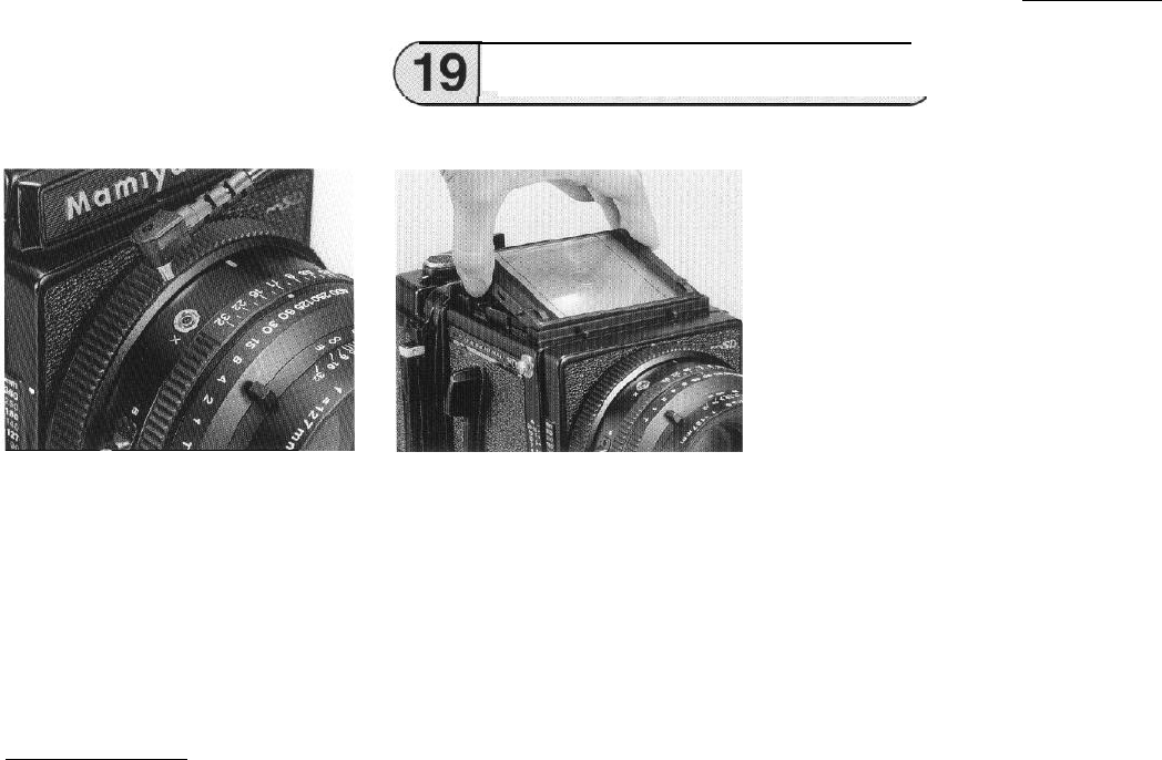
Changing the Focusing
Screen)
Attaching and detaching
First remove the waist-level finder, then while
holding both sides take out the
focusing
screen.
To attach it, hold each side and insert the
focusing screen into the top of the camera body
and press down lightly.
NOTE:
When the focusing screen has been
detached, do not touch the picture format red
rod indicator on the side of the camera body.
Seven types of interchangeable focusing
screens are available to meet various photo-
graphic applications.
l The
focusing
screen is made of
acrylic
resin, and since
its
surface is soft and sus-
ceptible to damage, be carefully so as to
not get fingerprints or other foreign matter
on it.
When dust is wiped off with a cloth or lens
paper, static electricity attracts more dust.
So, use a blower brush to remove dust.
(Guide number) 40
(Subject distance) 5 (m)
= (Correct aperture setting) 8
29
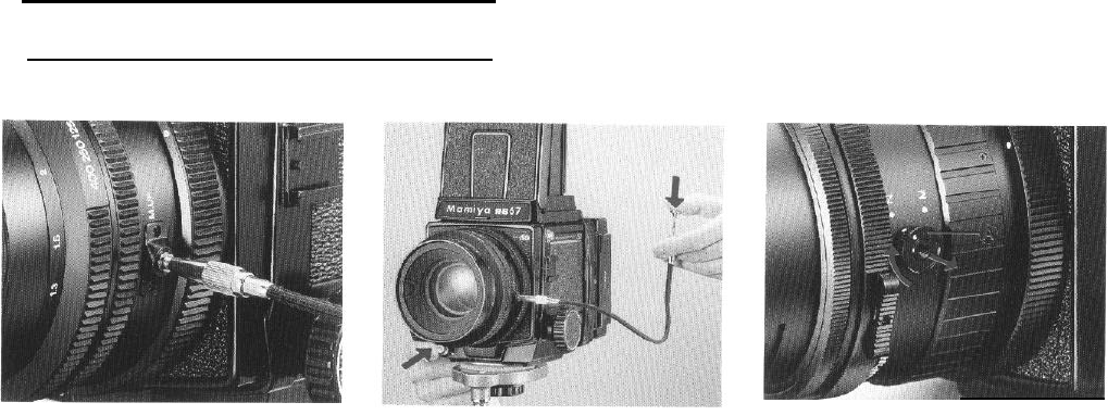
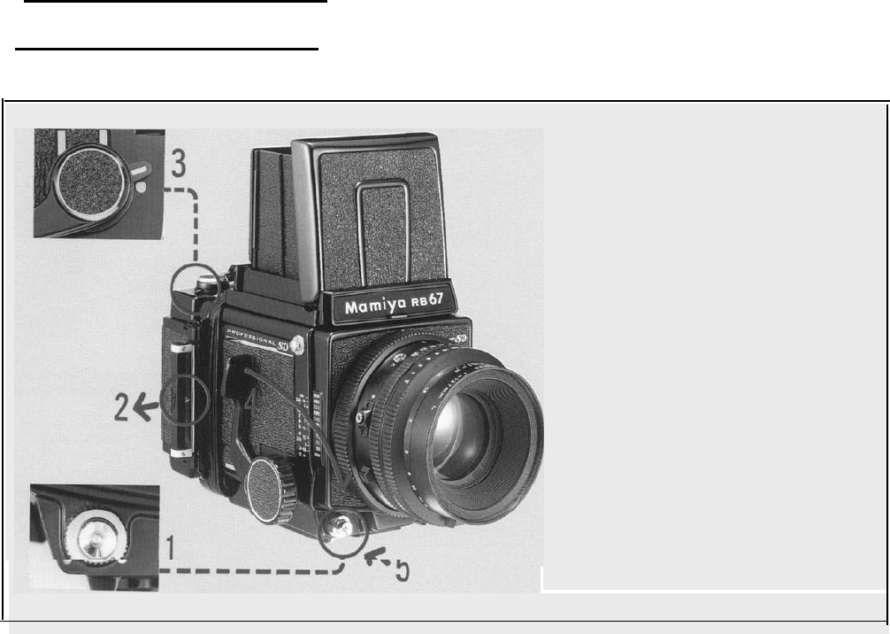
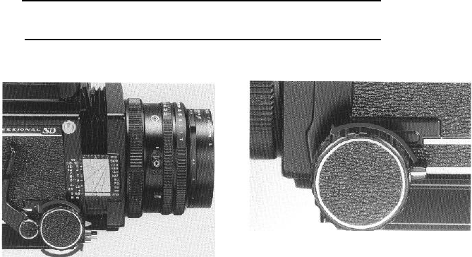
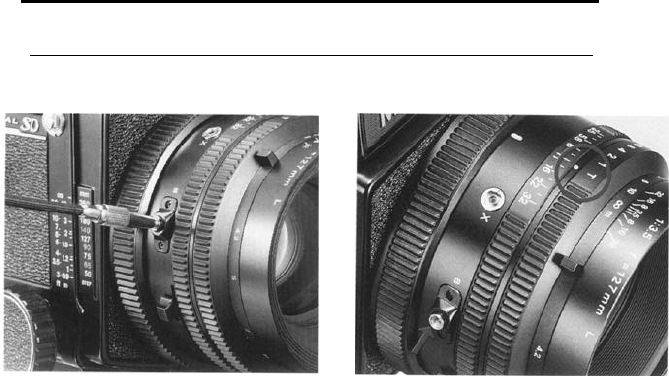
20. Mirror Lock-up Photography
The mirror lock-up technique, whereby the
mirror is raised beforehand and only the lens
shutter is released is ideal for situations where
vibrations must be
completely
eliminated.
Specifically close-up photography, using tel-
ephoto lenses and in
applications
where long or
slow exposures are necessary mirror
lockup
is
ideal. With a tripod and cable release, the mirror
lock-up mode ensures the utmost in sharpness.
Preparations
1.
For mirror lock-up operation, securely screw
a cable release into the lens socket as pictured.
When the socket slightly elevates the camera
will be in the mirror lock-up mode.
2. To cock the shutter and the mirror, press
the cocking lever forward as far as it will go.
Either Step 1 or 2 can be performed first.
3.
Upon depressing the shutter release button
the mirror will rise, but the shutter will remain
closed.
4.
Press the plunger of the cable release and
the shutter will operate.
NOTE:
l Unless the cable release is removed from
the mirror lock-up socket, the camera will
remain in the mirror lock-up mode and the film
30
cannot be exposed even when the shutter
release button is pressed.
When mirror lock-up photography is com-
pleted, be sure to remove the cable release. If
the red line around the mirror lock-up socket
is still visible, when
the cable release
is removed,
the camera is still in the mirror lock-up mode.
So,be sure that the cable socket sinks and the
red line disappears.
l As shown in the photo, some lenses use a
mirror release operating knob. When using a
lens with a knob, pull out the mirror release
operating knob (A), turn it clockwise, and
screw the cable release into the knob aligning
the red dot on the knob with the MIRROR
LOCK-UP indicator.
When mirror lock-up photography is com-
pleted, be sure to remove the cable release and
return the knob to its original position.
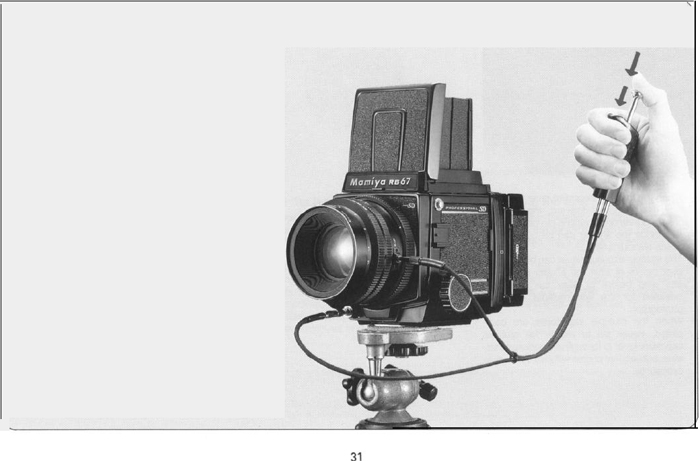
Using the Mirror Lock-up
Cable
Release
1. When
exposure
is shorter than 1 second:
(1) Screw the short cable into the mirror lock-up
socket, and screw the long cable into the
shutter release button.
(2) By pressing the cocking lever forward as
far as it will go,
cock
the shutter and
the mirror.
(3) The first stroke will make the mirror rise,
and the second will release the set speed.
*For lenses which use the mirror lock-up
operating knob, align the knob with the
MIRROR LOCK-UP indicator, screw in
the short cable, and screw the long cable
into the shutter button. The first stroke
will make the mirror rise, and the second
will release the set speed.
2.
When exposure is longer than 1 second,
it is convenient to integrate
with
time(T):
(1) Screw the short mirror release cable into
the bulb unit of the lens, and screw the long
cable into the mirror lock-up socket.
(2) Set the shutter speed ring to T.
(3) Raise the mirror by pressing the shutter
release button on the body.
(4) The first stroke of the mirror release will
open the shutter and the second stroke of the
mirror release will close it.
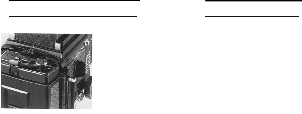
21 Multiple Exposure Photography 22 Close-up Photography
Exposure compensation for close-up
photography
When the bellows of the camera is
extended for close-up photography, and dis-
tance between the lens and the
film plane
increases, image brightness on the film plane
decreases, thus requiring an increase in expo-
sure. To adjust the exposure, refer to the
exposure compensation scale on the camera
body.
When a finder with built-in exposure meter
(i.e. PD Prism Finder or PD Magnifying Hood)
is used, exposure compensation is unneces-
sary, since TTL
metering
takes place.
When making exposure compensation,
refer to the exposure compensation scale on
the camera body.
When the multiple exposure lever of the roll
film holder is moved forward, the
multiple-
exposure prevention coupling pin disengages.
In this mode the shutter can be cocked and
released without limit.
l
The multiple exposure lever can be changed
over before or after the shutter is cocked,
and also before or after the shutter is
released for the first multiple exposure
photograph.
. When the multiple exposures are com-
pleted, never fail to return the multiple
exposure lever to its original position; other-
wise, subsequent photos will also be multiple
exposures.
32
Maximum close-up photography table with
1. After focusing the lens, read the exposure
compensation factor on the scale.
For example, assuming
that
the focus was
adjusted with the 127mm lens, the result will
be as shown in photo above.
Look for the same pattern in the bottom
column where the side panel lines meet the
127mm lens scale. The numerical value of
that pattem
(+1
in this case) is the
exposure compensation value.
2. Change either the shutter speed or
the
aperture for exposure compensation.
When the exposure compensation value is
+
1,
open the aperture one step, or slow the
shutter speed 1 step. For a 0.5 step
cornpen-
sation.
use the half-stop aperture scale settings.
For example, if your exposure meter shows
an exposure setting of
(1/60
sec. at f/16), it
must be adjusted in the case of the
+1
compensation value to
(1/30
sec. at f/16) or
(1/60
sec. at
f/11).
l When using
the
50mm and 65mm lenses
closer than 1 meter
(3%
ft),
it
is necessary
to use a lens aperture of
f/16
or smaller to
obtain
satifactory
lens performance.
l Graduations on the upper side of the
distance scale represents the
belows
extension values (mm).
This scale is used to obtain exposure
compensation values for close-up photo-
graphy with extension tubes.
33
Lens hood
The lens hood attached to the standard
127mm lens can be used for the
90mm
lens.
l
Screw
the
attachment
ring into the front of
the lens mount.
l Pull the folded rubber hood straight out.
l The lens hood may be left on when the
camera is being carried
-
simply push
back and turn out the hood while it is
attached to the lens.
l A filter can be screwed in between the lens
and the hood, or in front of the lens hood.
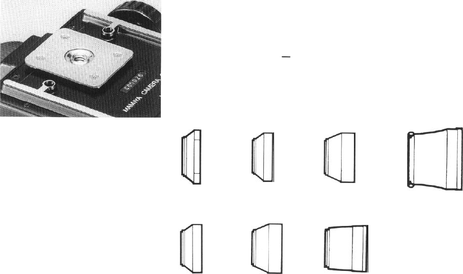
Using a tripod
The use of a large, sturdy tripod is recom-
mended for optimum picture quality.
1. The standard tripod has a
1/4
inch tripod
screw. Simply attach the RB67 Pro-SD as you
would any other camera with standard threads.
2. When using a tripod with a
3/8
inch screw,
first remove the small screw in the base of the
tripod socket by turning if counterclockwise
with a coin or an appropriately sized screw
driver. Next, remove the 1
/4
inch adapter (A)
from the tripod socket by rotating it counter-
clockwise. The camera can then be mounted
on a
3/8
inch screw tripod.
ul
Used on
50mm.
and Used on
90mm,
and
65mm
lenses
127mm
lenses
(80mmø
slip-on type)
(77mmø
screw-in type)
Q
%3
Used on
140mm,
150mm,
180mm,
210mm,
250mm,
For the 500mm lens
and 350mm lenses (IOBmma.
(77mmø,
screw-in type)
Q
a
For the
75mm
lens For the
100-200mm
f/3.5
lens
zoom
lense
(80mmø,
slip-on
type) (60mmø,
slip-on
type)
For
the
360mm lens
(77mm0,
screw-in
type)
34
(108mmø, slip-on type)
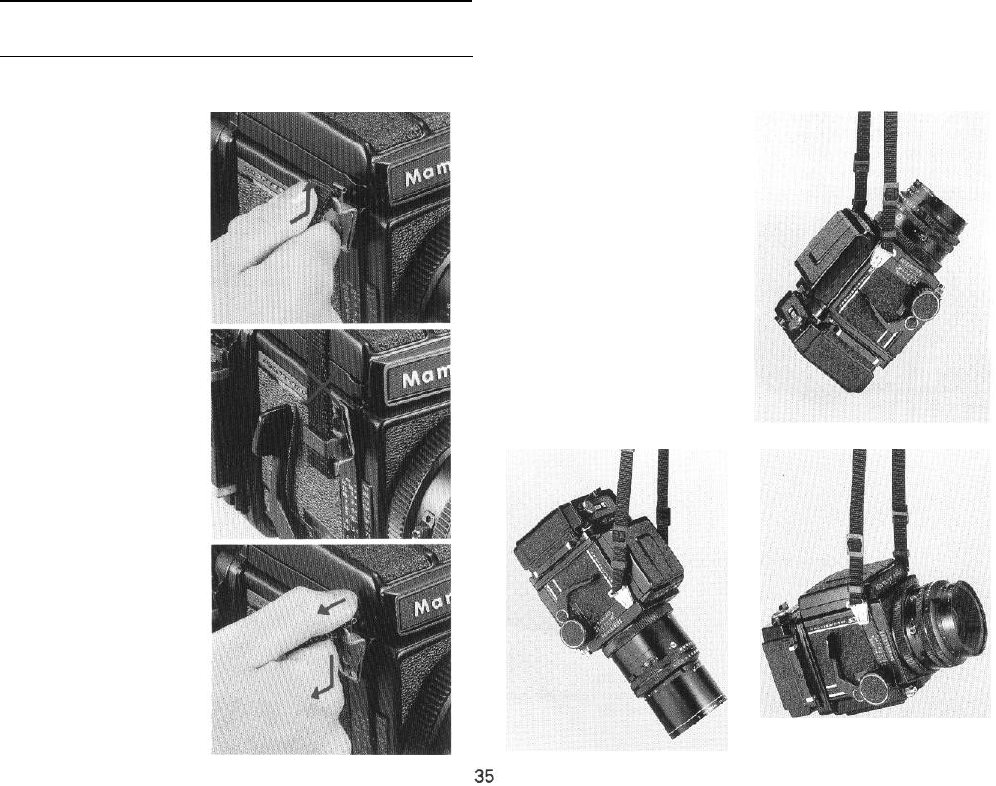
23
How to use the Carrying Strap
Attaching the Strap
Hold the metal clamp of the strap
so that the key-hole shaped open-
ing faces the Carrying Strap Lug on
the camera body. Gently fit the
upper
part
of the key-hole opening
over the lug. Next, gently push the
bottom of the metal clamp upwards
and it will lock in place with a click.
If the clamp is attached to
Accessory-shoe side of the camera
upside-down, it will be difficult to
remove, so be careful to attach the
clamp rightside-up.
Removing the Strap
Reach behind the strap and while
gently squeezing the top of the pro-
truding front plate (leaf spring), slide
the clamp downward and off the lug.
Three Carrying Positions
Depending upon the way the
strap is attached to the camera,
there are three ways of
carrying
the
camera as shown in the accom
panying
illustrations
Since the Car-
rying Strap Lug is not rotary, the car-
rying strap will not become twisted.
“‘.
b
24
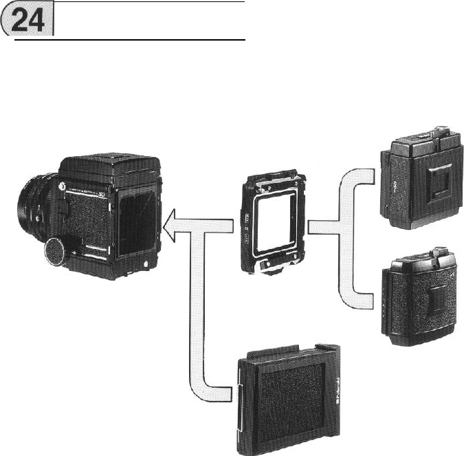
Back Locking System
The unique back locking system of the
Mamiya Pro-SD is designed to allow it to
accept a large variety of film holders. All
Pro-
SD
seies
film holders mount and lock directly
on the back of the Pro-SD.
Pro-SD
Revolving
adapter
AR-701
Pro-SD
120 Roll
film
holder HA-701
220 Roll
film
holder
HB-701
6x4.5
Film holder HA-702 (exclusviely
for
to be released soon.
6x4.5 Film holder HE-704 (exclusviely for
to be released soon.
RB
Pro-S 120 Roll film holder
Pro-S 220 Roll
film
holder
120/220
Power drive roll film holder 6x8
120/220 Power drive roll film holder 6x7
6x4.5 Film holder (exclusive for
120)
Double cut film/plate holder
70mm Film holder
120):
220):
Pro-SD
Polaroid pack film holder
HP-701
36
25
Lens Mount Adapter Ring
When using Mamiya Sekor C interchange-
able lenses with the RB67 Pro-SD, the lens
mount adapter ring must be used. It should be
attached to the rear lens mount. (When using
Mamiya KL lenses with the RB Pro-S and
RB67.
remove the lens mount adapter ring.)
. The lens mount adapter ring comes with
Sekor C lenses.
For KL lenses it is attached to the rear lens
mount.
.
Both the 75mm shift and APO 500mm lenses
are L lenses.
l Make sure to securely tighten the lens
mount adapter ring onto the lens mount.
I
Sekor
C
KL
L
RB67 Pro-SD The lens mount
adapter ring should
be attached.
RB67
Pro-S
The lens mount
adapter ring should
be detached.
37
Mamiya
RB67
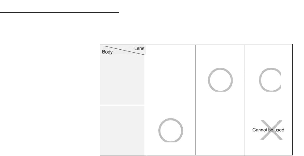
Pro-SD Operation Diagram
Attaching a lens with the shutter
released or the mirror raised
When a lens is removed from the body, the
mirror is set (lowered) and the lens shutter
cocked. Conversely, when attaching a lens,
the same conditions should prevail (mirror set
and shutter cocked). However, should a lens
be attached with either the mirror raised or
shutter released, or both, the camera can be
reset by following the procedures outlined
below.
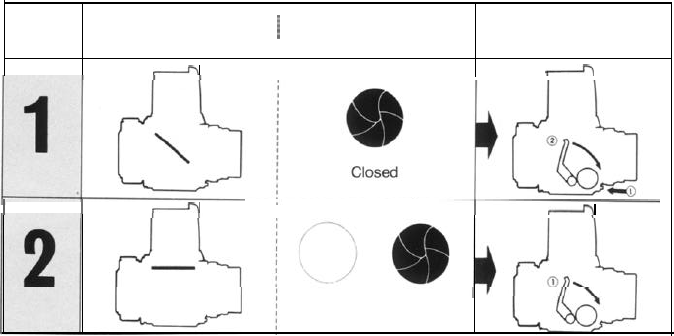
1.
If the mirror is raised (regardless of whether
the lens shutter is cocked or released), simply
depress the Cocking Lever to reset the cam-
era.
2.
If the mirror is set and lens shutter released
(closed), remove the Dark Slide from the Film
Holder and depress the Shutter Release But-
ton (the film will not be exposed). Next,
depress the Cocking Leverto reset the cam-
era.
Mirror condition
/
Shutter blade condition Operation
-
4
II
-
I
-
Opened or Closed
38
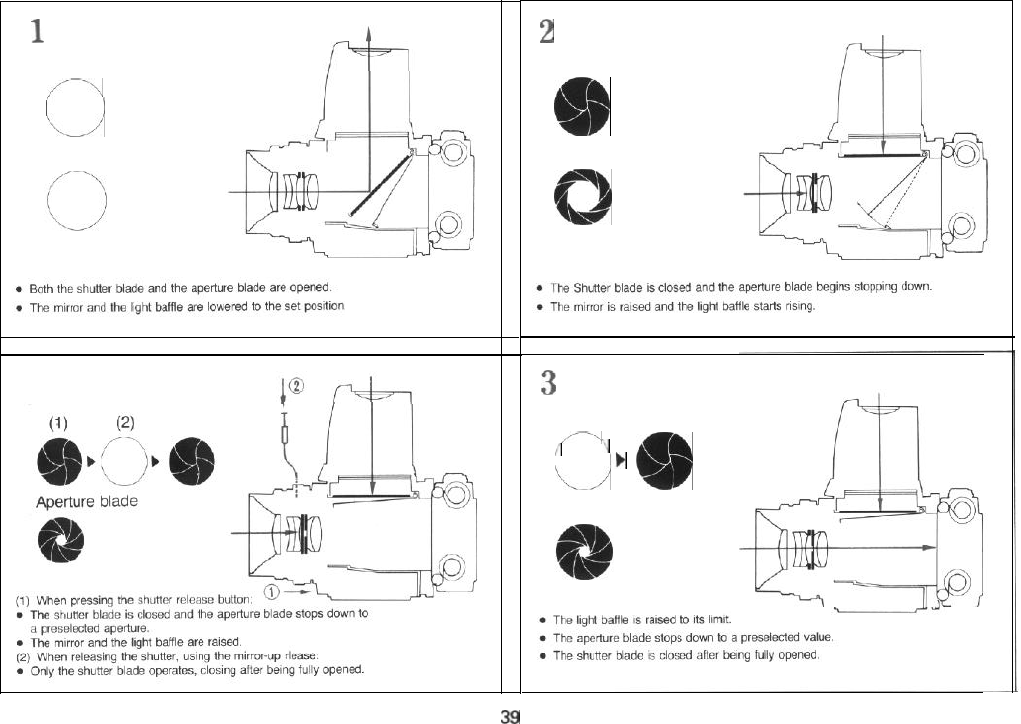
1
Shutter setting mode
Shutter blade
/--\
I
1-j
Aperture blade
Mirror-up photography
Shutter blade
1
2
Just after pressing the
shutter release
Shutter blade
&b
Aperture blade
0
3
Exposure
Shutter blade
/-\
i
:
1)
‘L/
m
Aperture blade
39

26
Trouble
Shooting
Various safety interlocking device are incor-
porated in the Mamiya
RB67
Pro-SD to
elimi-
4. After the shutter was released during
ordi-
nary exposure (not during multiple expo-
nate careless operational mistakes. When the sures),
did you advance the film?
shutter is not released, or when the lens or the
5. Was the dark slide pulled out?
roll film holder cannot be removed, do not Pull out the dark slide.
hastily conclude that this indicates a camera
malfunction. Check the following conditions: 6. Is the revolving adapter turned to the
click
stop
postion?
the numbers in parentheses indicate the page
number in the Instruction Manual that cover
relevant malfucntions.
Turn the adapter until it stops with a click.
(p. 20)
7. Has the slide lock on the revolving adapter
stopped halfway?
Move the slide lock until it stops. (p.4)
Shutter release button cannot
be depressed
1. Is the shutter release button locked?
Turn the shutter release lock ring coun-
terclockwise and align it with the white dot.
(p.13)
2. Is the mirror set?
Set the mirror by pressing the shutter
cock-
ing lever down.
3. Is the roll film holder loaded with film and
has the film and has the film been advanced to
the first exposure?
Lens cannot be removed
To remove, press the shutter cocking lever
down. Set the mirror and the shutter.
(p.10)
When mounting
the
film holder, won’t
the slide lock move?
While pressing the side lock release lever,
move the slide lock to the left. (p. 14)
Can’t the roll film holder be removed?
After inserting the dark slide, the slide lock
should operate.
40

71
Camera Storage and Maintenance
l
If
the camera is not to be used for a long
time, remove the film.
. Do not store the camera at temperature
exceeding
40°C
or below -10°C. Also
avoid storing in a damp or a sea air environ-
ment.
. As your camera is a precision instrument,
avoid exposing it to vibrations or severe
shocks. When handholding your camera,
always exercise extreme caution so that it
is not dropped or hit against something.
. Prolonged disuse does not lengthen cam-
era life, but shortens it. So, when storing it
for a long time, periodically take the cam-
era out and release the shutter several
times to keep it in good condition.
When using the
RB67
Pro-SD
for
special
important photos
for
on location photography,
weddings, overseas
trips
and or other important
photography, be sure to take
some
trial photos
and check all functions.
It is advisable to put your camera in for
periodic check-ups (at intervals of one to two
years)
to thus
ensuring
the best photography at
optimum performance.
Cleaning
l Never touch the surface of the mirror! If it
needs cleaning, use a blower brush or lens
paper to gently remove dust particles.
Please
note
the surface should never be
touched!
. Do not touch the lens surface. If a finger-
print gets on the surface, first remove the
dust particles with a blower brush. Then
gently wipe the fingerprint off with a lens
cleaning paper with a drop of lens cleaner
on it: finaly, gently wipe dry with dry
lens paper.
Periodic Check
Periodically check the camera to make sure
it is in working order. This is especially impor-
tant before beginning a photographic session
or assignment. Check the battery, flash syn-
chronization, mirror and shutter operation,
diaphgram funcitioning and film advance. Also
check any accessories you plan to use.
For a general overhaul, cleaning, or minor
repair, take the camera to your nearest au-
thorized Mamiya Service Center or see your
camera shop for advice.
41
