Mandolyn Electronic Technology TRC650 Wireless Thermostat User Manual 03 THM405R 52 0546 6 MANUAL ENG
Mandolyn Electronic Technology Inc. Wireless Thermostat 03 THM405R 52 0546 6 MANUAL ENG
User Manual

Table of Contents
Features ............................3
Installation Guide ....................4
Diagrams / Operation . . . . . . . . . . . . . . . . 15
LCD Display Diagrams . . . . . . . . . . . . . . . . . 16
Set ºC or ºF . . . . . . . . . . . . . . . . . . . . . . . . . 20
Set Clock . . . . . . . . . . . . . . . . . . . . . . . . . . . 22
Program Heating / Cooling . . . . . . . . . . . . . 23
Humidifier control . . . . . . . . . . . . . . . . . . . . . 26
Fan control / ventilation . . . . . . . . . . . . . . . . 27
System Mode . . . . . . . . . . . . . . . . . . . . . . . . 27
Temporary Override . . . . . . . . . . . . . . . . . . . 28
Hold Function . . . . . . . . . . . . . . . . . . . . . . . . 28
Pre-comfort Recovery . . . . . . . . . . . . . . . . . 29
Usage Monitor . . . . . . . . . . . . . . . . . . . . . . . 29
Filter Change . . . . . . . . . . . . . . . . . . . . . . . . 29
Remote sensor / transmitter ...........30
Optional Settings . . . . . . . . . . . . . . . . . . . . 33
Changing Batteries. . . . . . . . . . . . . . . . . . . . 39
Backlight . . . . . . . . . . . . . . . . . . . . . . . . . . . . 39
Memory backup . . . . . . . . . . . . . . . . . . . . . . 40
Reset. . . . . . . . . . . . . . . . . . . . . . . . . . . . . . . 40
Specifications . . . . . . . . . . . . . . . . . . . . . . . . 41
Troubleshooting . . . . . . . . . . . . . . . . . . . . . . 41

Thermostat
Compatible with central heating/air co nditioning system s for autom atic temperature con trol
Automatic change-over for HEATING/COOLING prog rams
Connects to humidifier for autom atic humidity con trol
Displays temperature (°C / °F)
Remote temperature con trol via remote sens or / transm itter
Extra-l arge LCD display with backlight
isplay (12 or 24 hou r format)
Temperature can be set in half de grees
Automatic, m anual and fan modes
Selectable cycle rates for furnace ON/OFF intervals
Usage monitor
Filter chan ge reminder
Compatible with millivolt & 24V heating system s
Include s mounting hardw are and 3 “AA” batteri es
l
l
l
l
l
l
l
l
l
l
l
l
l
l
Clock d
Remote Sen sor / Transmitter
urren t temperature and hum i y
Adjusts temperature with rem ote RF transmission
Temperature can be set in half de grees
Include s mounting hardw are and 2 “AAA” batteri es
l
l
l
l
Displays c dit
FEATURES
3

Installation
Guide
4

Introduction
This thermostat can replace common residential thermostats. It is designed for use with most
central heating and air conditioning systems that use low voltage (24V or millivolt) system control.
Please see compatibility chart on the next page for more details.
Warning
We recommend consulting a licenced HVAC contractor to ensure the correct installation of the
thermostat. The only way to guarantee proper wiring is to have a qualified professional on site.
Installation Guide
5
* NOT COMPATIBLE WITH ANY HIGH VOLTAGE 120/240 VOLT CIRCUIT.
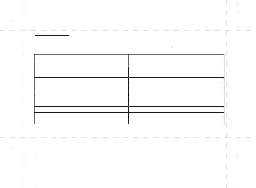
System Type
Gas - Standing Pilot
Gas - Electronic Ignition
Gas - Fire Boiler
Gas - Millivolt System
Oil - Fire Boiler
Oil - Fire Furnace
Electric Furnace
Electric Air Conditioner
Baseboard Electric Heater (120/240V)
Heat Pump/Single-Stage
Compatible with Thermostat
Yes
Yes
Yes
Yes
Yes
Some models
Some models
No
No
Yes
Compatibility
Generally, equipment with low voltage (24V or millivolt) system control is compatible with
heating/cooling programmable thermostats.
6
Heat Pump/Multi-Stage
No
* NOT COMPATIBLE WITH ANY HIGH VOLTAGE 120/240 VOLT CIRCUIT
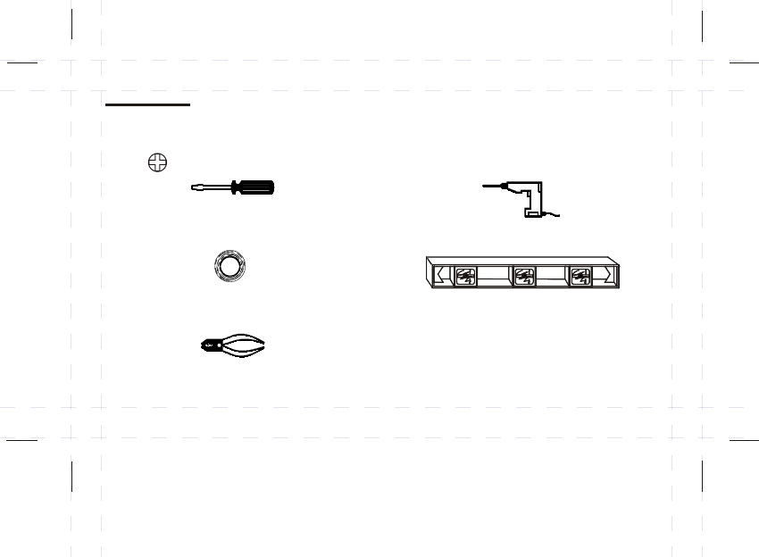
Batteries (included)
Wire Stripper/Cutter
(If necessary, to strip the wires)
Level
(If necessary, to level the thermostat)
Masking Tape
(To wrap the exposed wires temporarily and to label
the disconnected wires)
Power drill with a 3/16” bit
( If necessary, to drill holes on the wall )
( ) Screwdriver
Installation
The following tools may be required for installation:
7

Choosing a location for the thermostat
Thermostat should be mounted:
Approximately 5’ (1.5 m) from floor.
Near or in a frequently used room, preferably on an inside partitioning wall.
On a section of wall without pipes or duct-work.
Thermostat should NOT be mounted:
Near a window, on an outside wall, or next to a door leading outside.
Exposed to direct light or heat from a lamp, sun, fireplace, or other
temperature-radiating objects which may cause false readings.
Near or in direct airflow from heat registers and air conditioners.
Near concealed pipes and chimneys.
In areas with poor air circulation, such as behind a door or in an alcove.
l
l
l
l
l
l
l
l
8

Test the system to make sure that your heating and cooling systems are working properly before
installation If either does not work, contact a heating/air conditioning service person to fix the
problem before installation
TURN OFF POWER to system at the furnace, or at the fuse/circuit breaker panel
Carefully unpack your new thermostat and mounting plate; save package of screws,
instructions and receipt
l
l
l
(
)
9
Replacing the Old Thermostat
Wiring
NOTE: WIRING COLORS ARE NOT ALWAYS STANDARDIZED, SO IT IS VERY IMPORTANT TO
LABEL ALL WIRES ACCORDING THE LETTER DESIGNATION ON YOUR OLD THERMOSTAT
(The wires are usually designated 'W', 'Y', 'G', 'RH', 'RC', 'W' ,'B', ‘O' or humidistat wires
Disconnect wires from old thermostat or sub-base
As you disconnect each wire, label it with the old terminal designation
Take care not to let the wires fall back into the wall or let the ends of the wires touch one another
If there is an extra wire that is not connected to your old thermostat, then you won't need to connect
it to the new thermostat
)
l
l
l
l
10
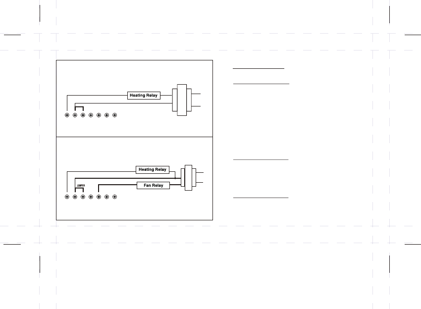
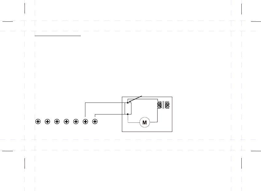
2-WIRE HEATING
3-WIRE HEATING
(OPTIONAL)
JUMPER
Wiring Key
Regular Wiring
G - Fan output
Y - Cool output
H1 / H2 - Humidifier control
Rc - Common for Cooling and Fan
Rh - Common for Heating
W - Heat output
2 Wire Heating
Rc / Rh - Common
(Rc and Rh jumper is optional)
3 Wire Heating
Rc / Rh - Common (Rc and Rh
must be connected with jumper)
G
YH2
H1
Rc
Rh
W
G
YH2
H1
Rc
Rh
W
Wiring Diagrams
11
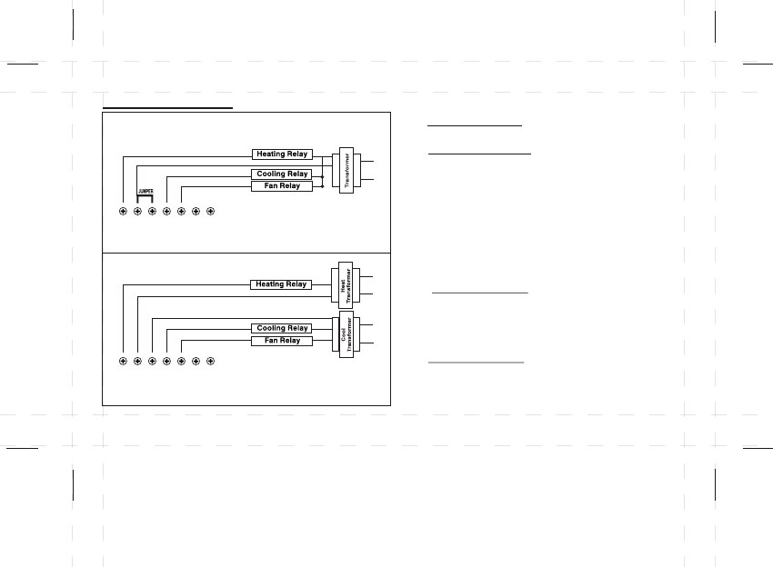
Wiring Key
Regular Wiring
G - Fan output
Y - Cool output
H1 / H2 - Humidifier control
Rc - Common for Cooling and Fan
Rh - Common for Heating
W - Heat output
4 Wire Heating
Rc / Rh - Common (Rc and Rh
must be connected with jumper)
5 Wire Heating
2 separate transformers (Heat / Cool)
Rc / Rh - Common (wire separately,
jumper must not be installed)
4-WIRE HEATING/COOLING
5-WIRE HEATING/COOLING
G
YH2
H1
Rc
Rh
W
G
YH2
H1
Rc
Rh
W
12
Humidifier Wiring
To wire a humidifier, the 2 wires connecting the original humidistat need to be
connected to the 2 terminals marked 'H1' and 'H2' on the thermostat.
The original humidistat should be removed or set to 'OFF' position.
Note: The 2 humidifier control terminals 'H1' and 'H2' are electrically isolated from the Heat/Cool
terminals.
Note: H1 and H2 terminals are non polarized and there is no function difference between H1 and H2.
l
l
Humidistat should be
OFF or disconnected
G
YH2
H1
Rc
Rh
W
Connecting the Wires to the Terminals
Connect the previously labeled wires to the corresponding
terminals, matching the designations. Use a screwdriver to
loosen the terminal, wrap the wires around the terminal then
tighten to securely fasten the wires. Make sure the wires do
not touch or short-circuit with other terminals.
Depending on your heating/cooling equipment, you may need to connect between 2 to 7 wires
If you have two ‘R’ wires, then connect each wire to its corresponding terminal and remove the
JUMPER between the RC and RH terminals
If you are unsure of the connections please consult a certified HVAC contractor for the correct
installation of your thermostat.
l
l
l
13
The back cover should be mounted vertically with the terminals on the top
Thread the existing wiring through the big center hole from the back and set the back cover
vertically on the wall
Select two appropriate mounting holes and mark the locations with a pencil (If necessary, use a
level to make sure the thermostat is positioned straight)
Remove the back cover from the wall and drill two 3/16 inch holes in the marked screw positions
Insert the wall anchors into the holes completely (If necessary, use a hammer to tap-in lightly)
Mount the back cover to the wall using the two screws (Make sure the metal terminals are on the top)
Attach the thermostat body to the back cover (that is already mounted on the wall)
by carefully aligning the two pieces and pressing firmly until they snap together
l
l
l
l
l
l
l
"
14
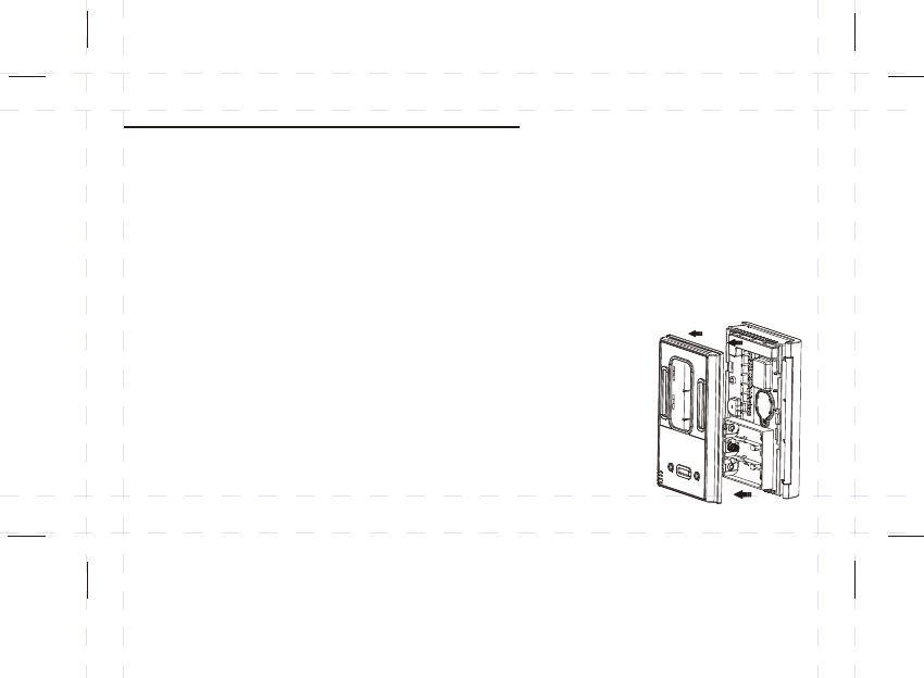
Mounting the back cover of the thermostat
First attach to backplate to the wall,
then press the faceplate into place
15
Diagrams and
Operation
16
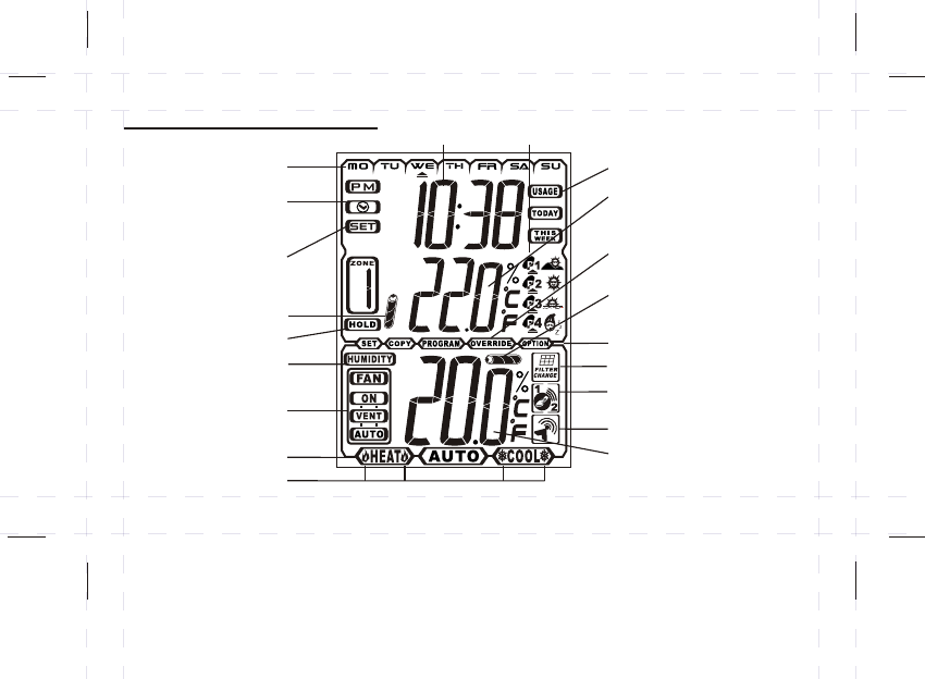
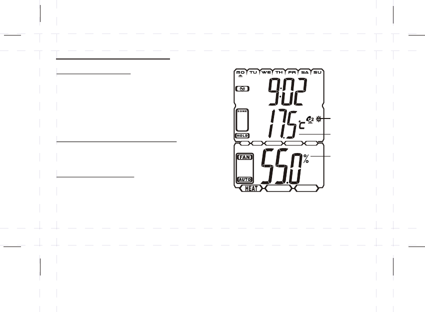
Thermostat LCD display CLOCK
WEEKDAY USAGE MONITOR
SET/PROGRAM
TEMPERATURE
THERMOSTAT TEMPERATURE,
REMOTE TEMPERATURE
AND HUMIDITY
PROGRAM
NUMBER
THERMOSTAT
LOW BATTERY
REMOTE SENSOR
LOW BATTERY
HOLD FUNCTION
OVERRIDE INDICATION
FILTER CHANGE INDICATION
HEAT/COOL RUNNING
FAN
VENTILATION MODES
SET OPTIONS
REMOTE SENSOR
TEMPERATURE CONTROL
REMOTE TEMPERATURE
SET CLOCK
HUMIDITY
OPERATION MODES
CLOCK SYMBOL
flashes when the
lithium battery is low
17
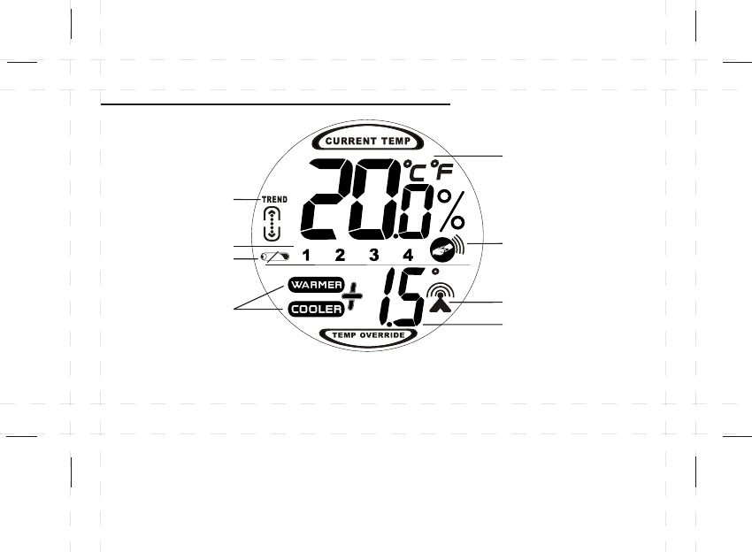
Remote Sensor / Transmitter LCD display
PROGRAM
NUMBER
LOW BATTERY
INDICATOR
TEMPERATURE OVERRIDE
(+ or - 3 degrees)
REMOTE TEMPERATURE
TRANSMISSION ICON
CURRENT REMOTE
TEMPERATURE
TEMPERATURE
TREND
REMOTE THERMOSTAT
CONTROL IS ACTIVE
OVERRIDE WARMER
OR COOLER
BUTTON LOCATION
18
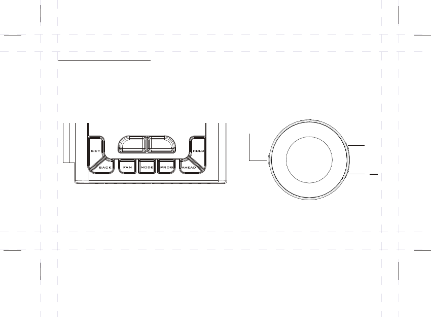
ON/OFF
+
THERMOSTAT REMOTE CONTROLLER / SENSOR
Temperature
Control
UP
DOWN
Press and hold the button on the top of the unit,
then gently but firmly remove the back cover
(DO NOT pry open with a screwdriver)
Insert 2 “AAA”
batteries
2
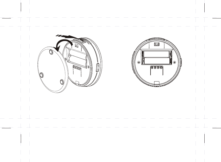
INSERT BATTERIES - REMOTE CONTROL / SENSOR
19
+
+
_
_
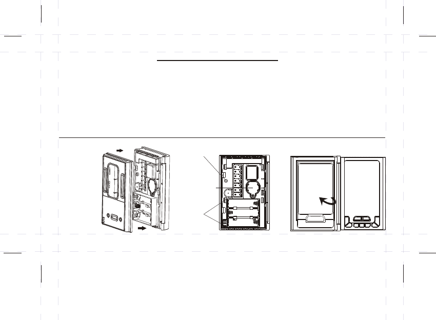
To prepare for
wiring, gently
pull off the
back cover,
DO NOT
pry open
Flip cover
open
to access
the buttons
Insert
3 “AA”
batteries
RESET
(R) key
CELSIUS DEFAULT: Since Celsius (°C) is the default mode no action is required to
use the thermostat in this mode. However, if you wish to choose Fahrenheit (°F) you
must do so before you begin using the thermostat. If you proceed to set the clock
and program settings with the default Celsius(°C)and THEN change to Fahrenheit (°F);
the clock, programs and all system settings will be deleted. To change the temperature
scale see the “Optional Settings” section.
IMPORTANT - (°C or °F)
** **
REMOVE BACK COVER / INSERT BATTERIES / PRESS RESET / ACCESS BUTTONS
20
Lithium
battery
for memory
backup
21
Current
program
period
Program
temperature
Check Pro grams
Press PROGRAM at any time to scroll
through and check all other prog rams
The current prog ram setti ng is displayed
in the middle of the LCD screen
Press PROGRAM repeatedly to return to the
norm al display
Local/Remote Temperature
The local/r emote temperature is displayed
on the bottom of the LCD screen
Relati ve Humidity
Relative hum idity is displayed on the bottom
on the LCD screen
It is shown alt ernatively with current (room)
temperature (The display alt ernates: 2 seco nds
humidity display , 4 seco nds temperature display)
l
l
l
l
l
l
Current
(room)
temperature
display,
alternating
with the
relative
humidity
display
Thermostat LCD display

22
Set clock
-
-
-
-
Set 12 or 24 hour format
- Press SET to begin setti ng the time (the TIM E sym bol wil l appear)
Press AHEAD or BACK to set the current time
Press SET again (the DAY symbol will appear)
Use AHEAD or BACK to set the current day
Press SET again to exit
12 hou r mode is the defau lt, so no acti on is required to use the thermostat in this mode
To select 12 or 24 hour format:
- Press SET for 3 seconds to enter the optiona l setting mode
- Press UP/DOWN to select 12 or 24 hour format
- Press SET to confirm
- Press SET repeatedly to exit the optiona l setting mode
Program Heating and Cooling
This thermostat is equipped with 5+1+1 DAY PROGRAMMING. Program Monday-Friday as a group
+ Saturday + Sunday, with 4 settings per day. This thermostat is pre-programmed for your
convenience or you can set your own programs as desired.
P1: MORNING
P2: DAY
P3: EVENING
P4: NIGHT
In the morning period, when you wake up, you may prefer a warmer temperature.
The daytime period is an energy-savings mode for the time you are away from home.
The settings can be adjusted to minimize energy consumption.
The evening period is for when you return home and want the house at a comfortable
temperature, typically set warmer during the winter and cooler during the summer.
The night period is the time when you are usually asleep. You may choose to lower
the temperature for energy savings and comfort.
:
:
:
:
PERIOD
MORNING
DAY
EVENING
NIGHT
P TIME
P1
P2
P3
P4
6:00am
8:00am
5:00pm
10:00pm
HEAT SETPOINT COOL SETPOINT
o o
69.0 F (20.5 C)
o o
63.5 F (17.5 C)
o o
70.0 F (21.0 C)
o o
62.5 F (17.0 C)
o o
77.0 F (25.0 C)
o o
84.0 F (29.0 C)
o o
77.0 F (25.0 C)
o o
79.0 F (26.0 C)
DEFAULT PRE-PROGRAMMED TIME AND TEMPERATURE SETTINGS
23
Note: Program periods can
be set to different or the
same temperatures.
For example: Period 1, 2,
or 3 can all be set to (22 )
if you are home all day and
want the temperature to
stay warm, but at night it
can set cooler. (17 )
oC
o
be C
(SEE OPTIONAL SETTINGS SECTION)

Press MODE until the HEAT symbol appears
Press PROGRAM once (P1 and the PROGRAM symbol will appear on the display)
Press PROGRAM again to scroll through the day(s) you wish to program
(Monday - Friday mode will display first, then Saturday, then Sunday)
Press AHEAD or BACK to scroll to the desired start time for Period 1 (displayed as P1)
Press UP or DOWN to set the desired temperature for P1
After setting the desired time and temperature for P1, press PROGRAM again to advance to P2
Repeat the steps above to set the times and temperatures for P2, P3 and P4
After Sunday P4 is set, press PROGRAM again to exit the programming mode
2
1
3
4
5
6
24
Heating Program
- The heating and cooling programs are linked, so same program start times
(chosen for either heating or cooling) will automatically be applied to the other
- The HEAT temperature setting will always be at least 3°C (6°F) lower than the COOL temperature
setting, to prevent a mistake or overlap in temperature settings
- The PROGRAM button can also be used at any time to review all the set programs
- Tip: Press and hold down the AHEAD/BACK or UP/DOWN buttons to scroll through the numbers quickly
- Program times can be set in increments of 10 minutes
- Temperature can be set in increments of 0.5°
- The temperature range for heating is 5°C to 32°C (41°F to 89°F)
7
8

Setting the cooling program is nearly identical to setting the heating program
Press MODE until the COOL symbol appears
Press PROGRAM once (P1 and the PROGRAM symbol will appear on the display)
Press PROGRAM again to scroll through the day(s) you wish to program
(Monday - Friday mode will display first, then Saturday, then Sunday)
Press AHEAD or BACK to scroll to the desired start time for Period 1 (Displayed as P1)
Press UP or DOWN to set the desired temperature for P1
After setting the desired time and temperature for P1, press PROGRAM again to advance to P2
Repeat above steps to set the times and temperatures for P2, P3 and P4
After Sunday P4 is set, press PROGRAM again to exit the programming mode
2
1
3
4
5
6
25
Cooling Program
- The heating and cooling programs are linked, so same program start times (chosen for either heating
or cooling) will automatically be applied to the other
- The COOL temperature setting will always be at least 3°C (6°F) higher than the HEAT temperature
setting, to prevent a mistake or overlap in temperature settings (For example, if the initial COOL
program temperature was set at 24°C (75°F) and you decide to adjust the HEAT program temperature
to 24°C (75°F), the thermostat will automatically push the COOL program temperature up to 27°C (81°F)
- The temperature range is 8°C to 35°C (48°F to 95°F) for cooling
7
8
Humidifier Control
Verify the humidifier is correctly wired to the thermostat. (see installation guide or contact an electrician)
Ensure the thermostat is in HEAT mode
Press PROGRAM until the HUMIDITY icon displays
Set the humidity level using the UP / DOWN buttons
Note:
- The humidifier will automatically turn on if the relative humidity is lower than the humidity setting
- Humidity is set in increments of 5%
- The humidity level can be set from 20% to 70%
- The humidifier setting only functions when thermostat is in HEAT mode
- Humidity is not pre-programmable, it must be set manually
- When the humidifier is on, the HUMIDITY symbol will appear
- To de-activate the humidifier, scroll DOWN to it’s lowest setting
2
1
3
26
4
4

27
For automatic control of the fan, press FAN until the AUTO symbol appears
In cooling mode, the fan starts/stops with the cooling equipment
In heating mode, the fan is controlled by the heating equipment
There may be a few minutes of delay between the fan setting selection and the fan becoming activated
For the fan to run continuously, press FAN until the ON symbol appears
For the Automatic Ventilation feature - where the thermostat will turn the fan on periodically
for better ventilation press FAN until the VENT symbol appears
Press MODE to toggle between the modes
HEAT - The system is in HEAT mode and furnace or heating system is activated
COOL - The system is in COOL mode and air conditioner or cooling system is activated
OFF - If the thermostat is in the OFF mode, both the heating and cooling systems will be turned off,
and all programs will be disabled
When the heating or cooling systems are ON, the following symbols will display:
will flash when the heating system is running
will flash when the cooling system is running
l
l
l
l
Fan Control / Ventilation
System Mode: HEAT / COOL / OFF

This function will change the temperature temporarily until the next program period starts
Press the UP / DOWN buttons to set the desired temperature
- The OVERRIDE icon will display, to indicate the OVERRIDE function is active
- If the system is in AUTO mode, only the currently active mode (heat or cool) setting will be changed
- The thermostat has an automatic delay function to protect the heating and cooling systems from
irregular on/off sequences, so there may be a delay of several minutes before the override
setting will activate the heating/cooling system
Temporary OVERRIDE
28
1
1
HOLD Function
This function will maintain a constant temperature until it is turned off by pressing HOLD again
Press the HOLD button
Press the UP / DOWN buttons to change the temperature
Press HOLD again to release the hold function
- The HOLD symbol will display when the HOLD function is activated
- The HEAT/COOL system mode cannot be changed while HOLD is on
- The HOLD function disables all program settings, and new temperature will then remain the same,
until the HOLD button is pressed again
2
3
l
l
l
l
This thermostat is equipped with a ‘Pre-comfort Recovery’ system that will activate the heating or cooling in
advance of the actual set program time, so that the room will be at the desired temperature at the start of the
program time
When the thermostat is in ‘recovery’, the OVERRIDE symbol will be flashing
It is normal for the system to be activated earlier than the actual set program time (up to one hour)
The Pre-comfort Recovery can be disabled if desired. (See "Optional Settings”)
29
Usage Monitor
Pre-comfort Recovery
Filter Change
- USAGE TODAY automatically resets itself daily at midnight
- USAGE THIS WEEK automatically resets itself at midnight on Sunday
- A new week begins Monday morning
l The thermostat tracks the system "ON" time; the time the heating/cooling equipment is running
Press BACK once to view USAGE TODAY
Press BACK again to view USAGE THIS WEEK
The FILTER CHANGE indicator will display on the LCD screen when the system "ON" time (HEAT, COOL
or FAN) has accumulated to approximately 500 hours. It is an indication that the filter should be changed at
this time
To reset the FILTER CHANGE counter:
- Press and hold FAN for 3 seconds until the buzzer beeps, this will bring the counter back to zero
l
l

This thermostat is equipped with a remote sensor, which monitors the temperature in a remote location
and can control the thermostat by sending a radio signal.
Controlling the thermostat with the remote sensor / transmitter:
Note: If you wish to use the remote sensor make sure the RF option is set to RF1 (see optional settings)
The remote sensor is capable of doing three things:
lTransmitting the room temperature from a remote location to display on the thermostat LCD screen
lThe thermostat will heat o cool your home based on the temperature transmitted by the remote instead
of the temperature of the thermostat.
l Overriding the current temperature setting to raise or lower the temperature up to 3°C ( )
or 6 ° ( ).
r
Celsius
F Fahrenheit
REMOTE SENSOR / TRANSMITTER
30
31
REMOTE SENSOR / TRANSMITTER
THE LEARN PROCEDURE
- REMOTE TEMPERATURE CONTROL - REMOTE TEMPERATURE DISPLAY
The learn procedure initiates a radio signal connection between the transmitter and thermostat
To begin:
lremote transmitter near to
lPress and hold the BACK button on the for 3 second
he symbol flash
lelease the BACK button
lPress and hold the ON/OFF button o the remote transmitter
(The remote temperature control will flash on the remote’s LCD screen after 3 seconds)
lWhen the signal is receive , the thermostat will beep and you can
release the ON/OFF button on the remote transmitter
l
Bring the the thermostat
thermostat s
(until t remote temperature display begins to on the thermostat’s LCD screen)
R
n
LEARN d by the thermostat
A second beep will sound within 30 seconds, to indicate that the temperature data has
been received (after the 2nd beep, the remote data should display on the thermostat LCD
screen)
SYMBOLS:

Viewing the temperature of the remote transmitter:
The local and remote temperatures display alternates every 8 seconds on the thermostat LCD screen. To view the
remote transmitter temperature, press AHEAD on the thermostat. The temperature will be shown on the bottom
pane and the Remote Temperature Display symbol (antenna) will appear indicating the temperature displayed is
from the remote transmitter. If the bottom pane is already showing remote temperature (the Remote Temperature
Display symbol already on), pressing AHEAD key will show the local temperature of the thermostat.
Controlling the thermostat based on the remote transmitter temperature (Heating or Cooling):
The thermostat can heat or cool your home based on the temperature transmitted by the remote, instead of the
thermostat's own temperature. To begin, place the remote sensor in the part of the house you wish to use for
temperature control. Press the ON/OFF button on the remote transmitter until the Remote Temperature Control
symbol displays. The thermostat will now control the heating and cooling based on the temperature as sensed by
the remote transmitter. (Note: If the local temperature on the thermostat and remote vary by more than 4 degrees,
or either remote transmitter or thermostat battery is low, the remote function will be cancelled.)
Remote Override:
raise or lower the set temperature by up to 3 °C or 6 ° . Press the UP or DOWN buttons on
the remote override value displayed as a plus or
minus value on the LCD screen of the remote. It will also appear on the thermostat LCD screen, alternating with
the temperature .
Although the remote cannot permanently change the thermostat's program settings, it can temporarily override
the current program to F
to change the temperature in half degree increments. The will be
regular set on the thermostat
REMOTE SENSOR / TRANSMITTER
32

33
The thermostat has a number of OPTIONS which the user can change. (*NOTE: Adjust these settings
before programming the thermostat, because changing certain options will erase all programming)
There are 9 OPTIONS. To begin, press SET for 3 seconds to enter the optional settings mode, then
press UP or DOWN to select the VALUE. Once the correct value is displayed, press SET again to
confirm the setting and to advance to next option. The optional settings are explained in detail on the
next few pages.
OPTIONAL SETTINGS:
1) 12/24 - hour display format
2) CR - Cycle Rate setting (select cycle rate to match the heating equipment)
3) RE - Pre-comfort Recovery ON or OFF
4) BL - Backlight setting
5) RF - Remote Control ON or OFF
6) FN - Additional fan control settings for the humidifier and the HE/HG setting
7) SY - System (heat pump option)
8) PG - Default programs
9) C/F - (Celsius/Fahrenheit)
OPTIONAL SETTINGS
34
OPTIONAL SETTINGS
1) 12/24 hour display format
- Press and hold SET 3 seconds
- The SET OPTION symbol will appear and either 12hr or 24hr will appear
- Select your preference of 12hr or 24hr by pressing UP or DOWN
- Press SET to confirm the setting and to advance to the next option
2) CR - Cycle Rate setting (select cycle rate to match the heating equipment)
- Choose from Cr-0 to Cr-5 by pressing UP or DOWN (See Chart 1)
- Press SET to confirm the setting and to advance to the next option
Note: The default setting is Cr-4 for g . Cr-0 is a fixed span operation (no cycle rate) for
heating and cooling. Choosing the correct cycle rate for your system promotes energy efficiency and a
more stable temperature.
as or oil forced air
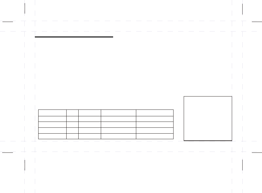
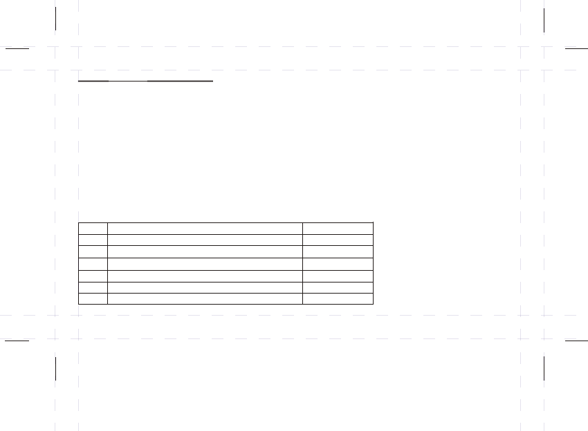
Chart 1
Cr
Cr-0
Cr-1
Cr-2
Cr-3
Cr-4
Syst em Cycl es per hour
–
Commercial Unit
Hydronic heat, condensing gas furnaces
Gas or oil forced air (default)
Electric Heat
Cr-5
–
+/- 0.3 °C fixed span
+/- 0.5 °C fixed span
2
3
5
7

3) RE- Pre-comfort Recovery ON or OFF
UP DOWN
- Press SET to confirm the setting and to advance to the next option
4) BL - Backlight setting
UP DOWN
1 = ON (If the backlight is enabled, pressing any button will turn the backlight on for 8 seconds)
BL0 = OFF
- Press SET to confirm the setting and to advance to the next option
.
5) RF - Remote Control ON of OFF
UP DOWN
1 = ON
0 = OFF (if OFF is selected all remote control features will be disabled)
- Press SET to confirm the setting and to advance to the next option
- Select the setting by pressing or
RE1 = ON (default)
RE0 = OFF
- Select the setting by pressing or
BL (default)
- Select the setting by pressing or
RF (default)
RF
35
OPTIONAL SETTINGS
6) FN - Additional fan control settings for the humidifier
- Press SET to advance to the next setting
UP DOWN
- Press SET to confirm the setting and to advance to the next option
HE: Use this setting for electric furnaces. With this setting,
the thermostat will turn the fan on immediately with the
heating system.
HG: Use this setting for gas or oil-fired furnaces.
This setting allows the fan operation to be controlled
by the heating system; not the thermostat. This is the
correct setting for most systems.
7) SY - System (heat pump)
UP DOWN
- Press SET to confirm the setting and to advance to the next option
- Select the setting by pressing or
- Select the setting by pressing or
SY0 = NON HEAT PUMP (default) recommended
SY1 = HEAT PUMP (single-stage) not recommended with most systems
SY2 = HEAT PUMP (multi-stage) not recommended
Fn
Fn-0
Fn-1
Fn-2
Fn-3
HE/HG
HG
HE
HG
HE
Fan operation for humidifier
(default) Humidifier on will not activate the FAN
Humidifier on will not activate the FAN
Humidifier on will turn on FAN
Humidifier on will turn on FAN
Additional fan control setting for the humidifier:
36
OPTIONAL SETTINGS

37
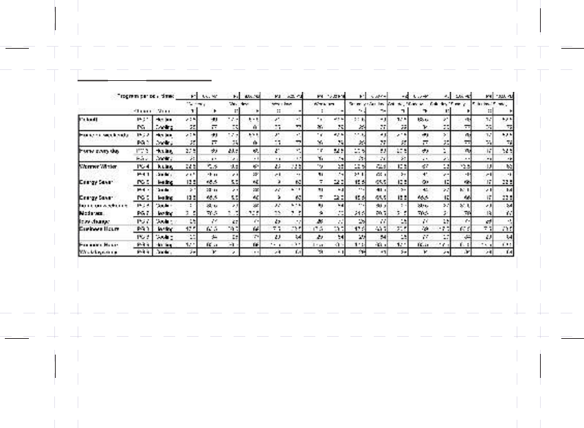
8) Default
9) C/F Selection
UP DOWN
- Press SET to confirm the setting and to exit the optional settings mode
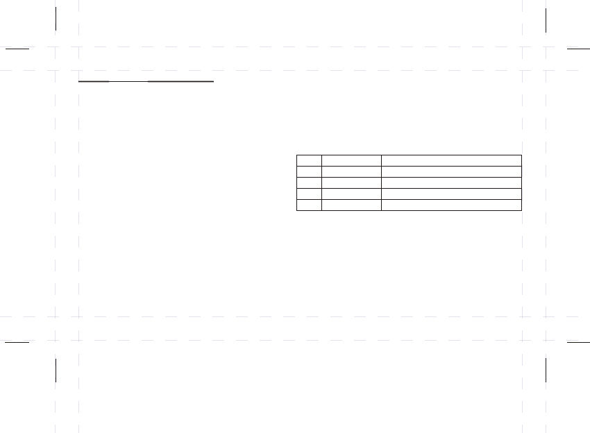
programs
This thermostat offers 9 weekly heating / cooling programs built-in for your convenience. The first
setting (PG1) is the main factory default which will auto-activate when you first install the thermostat.
Note: If you do not wish to change your current program settings, selecting PG0 will maintain the
existing program. (See chart 1 on the next page for a list of all program options)
- Select the setting by pressing or
C = Celsius (default)
F = Fahrenheit
Since Celsius (°C) is the default mode, no action is required to use the thermostat in this mode
To change the temperature scale display:
OPTIONAL SETTINGS
OPTIONAL SETTINGS
38
- Select the setting by pressing or to choose between 9 program selections PG1-PG9
Note: If you do not wish to change your current program settings, selecting PG0 will maintain the
existing program.
UP DOWN
Chart 1. - Default Program Options
When the AA batteries are low and need to be replaced the low battery symbol will appear on the
LCD screen and a beep will sound every hour. However, it is recommended that the batteries be
replaced every year, even if the battery symbol does not appear.
To replace the batteries:
Select OFF to change the thermostat to OFF mode
Remove the thermostat from its mounting plate (back cover) carefully
Remove the old AA batteries and install new ones
Place the thermostat back into its original position
Note: If the batteries are low the backlight will not turn on and the remote control feature will not
work. After changing the batteries, complete the LEARN PROCEDURE again to connect the
thermostat and remote sensor / transmitter. (see the remote sensor/transmitter section)
The backlight helps you to clearly see the thermostat display at night. However, frequent backlight
use will reduce your battery life. To disable the backlight see the “Optional Settings” section.
l
l
l
l
39
Changing Batteries
Backlight

40
Memory backup for the Programs and Thermostat Settings
In case of power outages, this thermostat has a memory backup powered by a lithium battery.
The lithium battery will typically last for several years. Memory storage includes all set programs
and thermostat settings. Do not remove the Lithium battery and the AA batteries at the same time,
otherwise all memory and settings will be lost.
SOFT RESET - If the thermostat has an abnormal display, press the RESET (R) button located at the
back of the thermostat. The programs and thermostat settings will remain stored in memory but the
clock will have to be set again.
HARD RESET - To clear the permanent memory (including all stored programs and settings) or to
change the temperature scale (°C or °F), a hard reset must be performed. Press and hold the
HOLD button, and at the same time press and release the RESET (R) key located on the back of the
thermostat. The LCD screen will blank out momentarily. When the display reappears, release the
HOLD key. The thermostat will be back to its default settings.
RESET
TROUBLESHOOTING GUIDE
Specifications:
Number of programs: 5+1+1 day programming, with 4 settings per day
Temperature setting range: 5 – 35°C (41 – 95°F)
Temperature display range: 0 – 55°C (34 – 99.5°F)
Humidity setting range: 20 to 70%
Humidity display range: 20 to 95%
Battery: 3 x “AA” size batteries
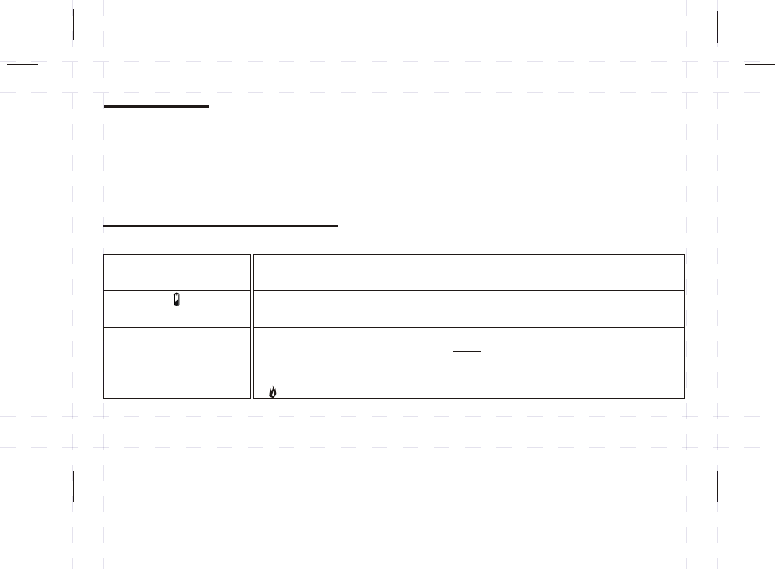
PROBLEM SOLUTION
Battery symbol ( ) is flashing.
LCD screen is blank.
Heat will not come on.
- Check if the batteries are installed correctly.
- Check if the batteries are fresh and of the correct type.
- Select RESET button on the back of the unit.
- This is an indication that the batteries are running low. Replace with fresh alkaline batteries.
Note: We recommend replacing the batteries at least once a year even if the battery symbol is
not flashing.
1) Check and ensure that the thermostat is set to the HEAT or AUTO mode.
2) Check and ensure that the set temperature is higher than the current (room) temperature.
3) You may have to wait up to 5 minutes before the heat will turn on. The thermostat has a built-in time
delay to prevent undesirable on/off sequences.
4) After a 5-minute wait, the heat should now be on. Whenever the heating system is running, the
symbol will be animated.
41
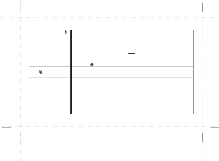
PROBLEM SOLUTION
Heat will not come on but the
symbol is animated.
Air conditioning will not come on.
Air conditioning will not come on
but the symbol is animated.
The thermostat turns the heating
or cooling systems on before my
programmed set times.
Heating system seems to cycle
too often.
1) Check if the furnace switch and/or pilot flame is turned on, as it may have been turned off.
2) Allow several minutes for the heating system to heat up and the fan to activate. Most heaters will heat
up the system for a short while before warm air can be ventilated by the fan. Also check that the
HE/HG setting is set correctly. (see optional settings)
3) If the heat still does not come on, check the wiring installation again.
1) Check and ensure that the thermostat is set to the COOL or AUTO mode.
2) Check and ensure that the set temperature is lower than the current (room) temperature.
3) You may have to wait up to 5 minutes before the air conditioning will turn on. The thermostat has a
built-in time delay to protect the air conditioner compressor from undesirable on/off sequences.
4) After a 5-minute wait, the air conditioning should now be on. Whenever the cooling system is
running, the symbol will be animated.
1) Check if the air conditioning system’s main switch is turned on, as it may have been turned off.
2) Wait several minutes for the air conditioning system to activate. If the air conditioning still does not
come on, check the wiring installation again.
This is normal if the Pre-comfort Recovery system is enabled. The Pre-comfort Recovery will activate
the heating/cooling in advance of the actual programmed set time so that the room will be at the
desired temperature at the start of the program time. See the “optional settings” section.
Check and ensure that you have selected a Cycle Rate that matches your particular heating system.
If you find it still cycling too often, you may wish to try a slower cycle rate or disable the cycling.
When disabled, the thermostat will operate at a fixed span of (plus or minus) ±0.5°C (±1.0°F).
For example, if the programmed temperature is set at 20°C (68°F), the thermostat will turn the heat
on if the current (room) temperature falls below 19.5°C (67°F) and turn the heat off when the current
(room) temperature reaches 20.5°C (69°F). See the “optional settings” section.
42
PROBLEM SOLUTION
Thermostat is set on AUTO mode,
but the thermostat does not seem
to automatically change-over from
HEAT to COOL or vice-versa.
While adjusting the program
temperature or program times
in the HEAT mode, you notice the
changes affect the settings in
the COOL mode; and/or
vice-versa
Cannot change the thermostat
scale from °C to °F or vice-versa.
The thermostat has a built-in safeguard time delay of 30 minutes to prevent undesirable change-over
sequences from HEAT to COOL or COOL to HEAT. For example, if the thermostat was just running the
cooling system, it will take at least 30 minutes before it changes to heating. You may override this
manually by pressing MODE to change the operation to HEAT or COOL only.
The heating and cooling program times are linked, so same program start times (chosen for either
heating or cooling) will automatically be applied to the other.
When you set the HEAT and COOL program temperatures fairly close to one another, the thermostat
automatically restricts the two temperature settings from getting within 3°C (6°F) of one another.
The COOL temperature setting will always be at least 3°C (6°F) higher than the HEAT temperature
setting. For example, if the initial COOL program temperature was set at 24°C (75°F) and you decide
to adjust the HEAT program temperature to 24°C (75°F), the thermostat will automatically push the
COOL program temperature up to 27°C (81°F) to prevent overlapping.
Selecting the temperature scales is a one-time start-up process. After the first battery installation, you
must HARD reset the thermostat and choose the desired display in °C or °F. Otherwise, you CANNOT
change the temperature scale (°C or °F) later on unless you perform another HARD reset which will
clear all the programs and thermostat settings.
To perform a HARD reset and select °C or °F, first press and hold the HOLD, while at the same
time press and release the RESET button on the back of the thermostat. The LCD screen will blank
out momentarily. To select °F, select see the “optional settings” section.
43
The thermostat is not receiving a
signal from the remote transmitter.
Re-do the “Lean Procedure” to ensure an RF signal is being transmitted from the remote sensor to
the thermostat. (See “Remote transmitter” section)
The clock symbol is flashing This indicates that the 3V (CR2025) lithium battery is low. This will not affect the normal operation
of the thermostat, but it should be replaced to ensure memory backup is maintained. Replace the
lithium battery with a screwdriver. (See diagrams for the location of the lithium battery)

FCC Statement
The statement required by 15.105 is as follows:
This equipment has been tested and found to comply with the limits for a Class B digital
device, pursuant to Part 15 of the FCC Rules. These limits are designed to provide reasonable
protection against harmful interference in a residential installation. This equipment generates,
uses and can radiate radio frequency energy and, if not installed and used in accordance with
the instructions, may cause harmful interference to radio communications. However, there is
no guarantee that interference will not occur in a particular installation. If this equipment does
cause harmful interference to radio or television reception, which can be determined by
turning the equipment off and on, the user is encouraged to try to correct the interference by
one or more of the following measures:
- Reorient or relocate the receiving antenna.
- Increase the separation between the equipment and receiver.
- Connect the equipment into an outlet on a circuit different from that to which the receiver is
connected.
- Consult the dealer or an experienced radio/TV technician for help.
Statement required by 15.19 and RSS210
This device complies with Part 15 of the FCC Rules and with RSS-210 of Industry
Canada.
Operation is subject to the following two conditions:
(1) this device may not cause harmful interference, and
(2) this device must accept any interference received, including interference that
may cause undesired operation.
Manual Requirements according 15.21
NOTICE:
Changes or modifications made to this equipment not expressly approved by UPM may
void the FCC authorization to operate this equipment.
ICES - 003
The statement required by ICES - 003 is as follows:
NOTICE:
This Class B digital apparatus complies with Canadian ICES-003.
Cet appareil numérique de la classe B est conforme à la norme NMB-003 du Canada.