Mandolyn Electronic Technology WT460 Remote Control Transmitter User Manual WT460 DSN RT301A4B SCH
Mandolyn Electronic Technology Inc. Remote Control Transmitter WT460 DSN RT301A4B SCH
User Manual
SETSET C/FC/F
--
AA 1.5VAA 1.5V
++
--
AA 1.5VAA 1.5V ++
SETSET C/FC/F
--
AA 1.5VAA 1.5V
++
--
AA 1.5VAA 1.5V ++
OUTOUT
11
Date Setting:
Scroll to date mode using MODE
Press HOUR/+/MAX to set month
Press MINUTE/-/MIN to set date
Weekday is automatically determined
from the year/month/day setting
DATE, YEAR & ALARM SETTING
a
b
c
d
February will have either 28 or 29 days
depending on the year setting
Year Setting
Scroll to YEAR mode using MODE
Press + or - key to adjust year
e
f
P.6
c
ae
d
f
battery installation
GETTING STARTED
remove battery cover
2 AA size batteries (WS295)
2 AA size batteries (WT460H)
(included)
Insert between terminals observing
proper polarity then replace cover
1
2
3
4
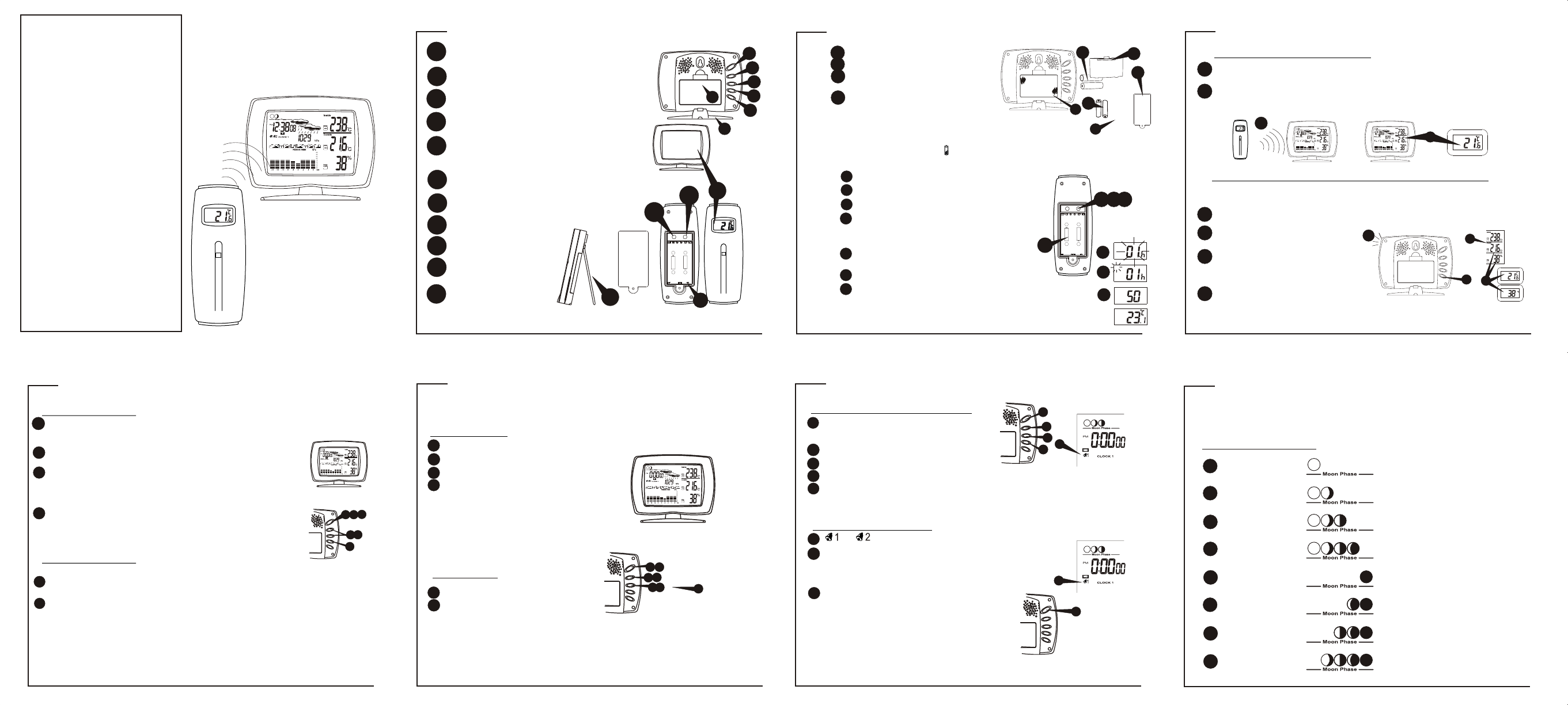
WS295+WT460H
Wireless Weather Station
with weather forecast
OWNERS MANUAL
Congratulations on your purchase of this weather
station, WS295. Please take the time to read and
understand this manual so you can begin to enjoy
the convenience and features this product has to
offer.
The WS295 is a weather station device that has
several weather related functions. The main
features are:
Main Display Unit:
*
*
*
*
*
*
*
*
*
*
*
Remote Sensor WT460H:
* drip-proof design with LCD
* temperature display in user-selectable C or F
* humidity display
* transmission range: up to 40 meters in open area
* battery type: 2 x AA size
Perpetual Calendar
Local temperature and humidity display
Pressure reading display
Receives and monitors temperature and humidity
from up to 3 remote sensors via RF technology of
433MHz
Maximum/minimum temperature records
Temperature and humidity trend indicator
Pressure historical bar graph
Temperature alarm (local and remote)
Animated weather forecast symbols
Moon phase symbols
User-selectable C or F
Battery: 2 x AA size
GETTING STARTED button placement
1
6
2
3
4
5
MINUTE/-/MIN: shows minimum temperature; adjusts
clock, alarm, date & year and temperature alarm values
SNOOZE/MODE: scrolls through Clock 1 & 2, Alarm 1 & 2,
Date & Year, and Temperature Alarm(high & low) mode;
snooze for alarm
Table Stand
ALARM/(C/F): toggles between C and F, 12 and 24 hour
format, Alarm 1 & 2 on and off; disables (resets) high &
low temperature alarms
CHN: scrolls through remote channels (1 to 3); scrolls
through local and remote channels (1 to 3) in (high &
low) temperature alarm mode; activate learn process
HOUR/+/MAX: shows maximum temperature; adjusts
clock, alarm, date & year and temperature alarm values
Synchronization
1
1
2
2
3
4
SETUP
Automatic Learn Function:
Manual-Learn (Searching for Remote Signals):
Learn function executes automatically and runs for approximately
3 minutes when batteries are first installed in the receiver.
Press and hold CHN for 3 seconds to start
If a new remote sensor is added or if signal is lost (outdoor display
blinking), learn function must be executed again.
Within these 3 minutes, receiver picks up the temperature &
humidity signals from remote sensor and displays the readings.
Beep sound indicates that
learn function has started
'Outside' symbol will flash and
unit will beep as each remote
sensor is detected
Temperature & humidity readings of
remote sensor displays on the receiver.
Clock 1 Setting:
Press and hold MODE for 3 seconds to enter the clock setting mode
(the CLOCK 1 symbol appears and the time will flash)
Press HOUR to set the hour and MINUTE to set the minute;
Press ALARM/(C/F) during clock setting, to change between
12 and 24 hour display. This also will end clock setting
(to clear the second record by pressing CHN key)
Press MODE or do not press any key for 1 minute to finish
clock setting.
Clock 2 Setting:
Scroll to Clock 2 mode using MODE
Press + or - key to change the hour
(in one hour increments/decrements relative to Clock 1)
CLOCK SETTING Manual clock setting
i
ii
iii
iv
vi
v
P.1
P.5 P.7
P.4
P.8
WS295
receiver
2
2
1
LOW BATTERY INDICATION:
Receiver: Low battery indicator will display continuously when batteries
need replacing. On transmitter, will be displayed
P.2
Alarm 1and Alarm 2 Setting
Scroll to Alarm1 mode (Alarm2 mode)
using MODE
Press HOUR to set hour
Press MINUTE to set minute
Press ALARM to toggle alarm on and off
When the alarm is set ON, the bell symbol will appear
When Alarm Sounds
or will flash
Press SNOOZE to snooze the alarm for
5 minutes.
After that the alarm will sound again.
Press ANY other key will shut off the alarm.
Without interruption, alarm will shut off
automatically after one minute.
DATE, YEAR & ALARM SETTING
1
1
2
2
3
3
4
5
1
2
2
1
45
P.3
i
iii
iv v
vi
ii
Moon Phase Display
MOON PHASE
The moon phase is automatically updated
according to the year/month/day.
New Moon
Young Crescent
First Quarter
Waxing Gibbous
Full Moon
Waning Gibbous
Last Quarter
Old Crescent
1
2
8
7
6
5
4
3
2
WT460H transmitter
7
10
11
8
9
SET: enter to House code and Channel
setting mode
C/F: change between C or F, change
channel and house code
Battery compartment
LCD display
Wall Mount Holder &
Table Stand
7
8
99
setting remote transmitters
* Use a different house code if your weather station detecTs other
signals from neighboring sources
* Factory default: house code = 01 and channel = 01
2
4
6
335577
111
1
1
%
1
1
OUT
1
1
4
3
OUT
1
OUT
1
1
4
3
1
2
3
5
4
6
9
10
bf
3
11
OUT
1
OUT
1
4
3
1
4
5
Insert batteries to start setup
HOUSE CODE will flash for 8 seconds
Select HOUSE CODE (1-15) by pressing C/F
CHANNEL will flash for 8 seconds
Select CHANNEL(1-3) by pressing C/F and
pressing SET
2
Transmitters for each receiver must be set to
the same HOUSE CODE and pressing SET
6
7
Humidity & Temperature will display
Select C or F of Temperature by pressing C/F
and pressing SET
P.9 P.10
P.16
P.12
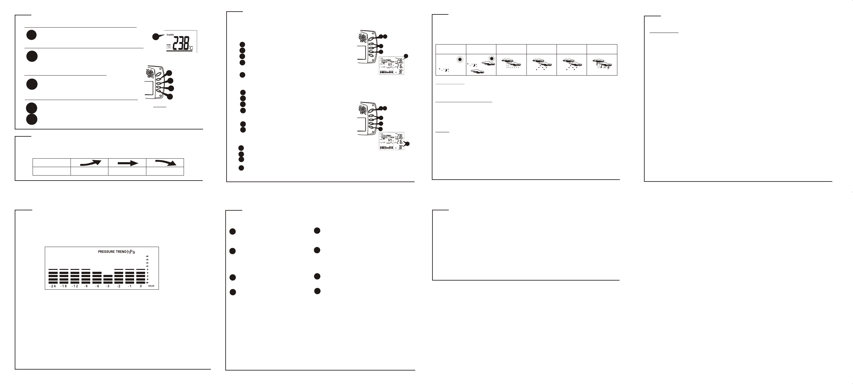
PRESSURE HISTORICAL BAR GRAPH
The bar graph lets you see the pressure trend over a period of 24 hours
in 3-hour intervals.
P.13 P.14 P.15
P.10
Check Remote Temperature & Humidity
Check Local Temperature & Humidity
C or F Temperature Display
Min and Max Temperature & Humidity
A
**
B
C
D
TEMPERATURE & HUMIDITY DISPLAY
Press CHN to toggle between Channel 1, 2 and 3.
Temperature and humidity readings will alternate
display on the receiver.
After insert batteries, local temperature and
humidity readings will display.alternate
Toggle between C and F by pressing
C/F at Clock2 mode.
Press MIN in Clock1 mode to display
minimum temperature and humidity
Press MAX in Clock1 mode to display
maximum temperature and humidity
Note:
Min/Max readings are
automatically cleared
daily at 00:00
The trend indicator shows the trend of temperature & humidity
determined by the particular sensor in the past half hour interval.
Arrow Indicator
Rising Steady Falling
Trend
Temperature & humidity trend
A
Press ALARM key continuously to scroll and select the high
temperature alarm, low temperature alarm or disable the alarm function
Press + or - key to set the temperature limit value
Press MODE to finish
The default value 14C or existing preset will flash
a
*
2
b
5
c
3
4
when temperature alarm sounds
Press any key to stop temperature alarm; or
If no key is pressed, the temperature alarm will automatically stop
itself after one minute.
Once triggered, temperature alarm comes on as a distinctive
sound, different to that of Alarm1 and Alarm2.
It is to alert that the temperature has exceeded the preset temperature limit.
Remote temperature alarm
1 5
*
Scroll to remote channel temperature alarm mode by using MODE
Press + or - key to set the temperature limit value
Press CHANNEL to select one desired channel of transmitter
The default value 14C or existing preset will flash
1
2
5
6
3
4
*
Press MODE to finish
15
Press ALARM key continuously to scroll and select the high
temperature alarm, low temperature alarm or disable
the alarm function
6
Scroll to local temperature alarm mode by using MODE
1
TEMPERATURE ALARM
You can set high temperature or low temperature alarms
for one local and one for one remote channel
Local temperature alarm
5
This weather station is capable of detecting barometric pressure changes, and based on
the data collected, can predict the weather for the next 12 to 24 hours. The effective range
covers an area of 30 – 50km.
Storm Alert
* Storm symbol will flash to warn of thunderstorm.
About Freeze Warning
* Snow symbol will flash to warn of 'freezing'.
* Activated when Channel 1's temperature is between -1.9 C and +2.9 C
* Snow will appear solid if and when Channel 1's temperature falls below -1.9 C.
Note:
* Remote sensor Channel 1 will be used for weather indication.
animated weather forecast symbols
WEATHER DISPLAY
Raining
Freeze
Warning Storm Alert
Snowing
Sunny Cloudy
<flashing snow>
OR OR
REMARKS:
* After setting up, reading for weather forecasts should be discarded for the
next 12-24 hours. This will allow sufficient time for the Weather Station to
operate at a constant altitude and therefore result in a more accurate forecast.
* Common to weather forecasting, absolute accuracy cannot be guaranteed.
The weather forecasting feature is estimated to have an accuracy level of about
75% due to the varying areas the Weather Station has been designed for use in.
* If the Weather Station is moved to another location significantly higher or
lower than its initial standing point (e.g from ground floor to 1st floor of a
house), remove the batteries and reinsert them after about 30 seconds. By
doing this, the Weather Station will not make mistake of new location being a
possible change in air pressure. Again, discard the weather forecasts for the
next 12-24 hours as this allow time for operation at a constant altitude.
WEATHER DISPLAY
B
C
D
3
4
1
3
4
SPECIFICATIONS
Weather Station Receiver WS295
Battery Type: 2 X 1.5V AA batteries
Temp. Range: 0°C to +55°C
Humidity Range: 20% to 90% RH
Measurement Accuracy: Max. +/- 1°C
within measuring range of 0 to 40°C
Resolution: 0.1°C
ii
ii ii
iii iii
iv iv
Place the clock away from metal objects or
electricalappliances such as TVs, computers,
monitors, etc.
Wait for about 1-2 minute to ensure the remote
sensor and receiver are in phase. Otherwise,
re-synchronize receiver by holding CHN for 3
seconds until a beep is heard.
Ensure the remote sensor is out of direct sunlight,
and away from sources of heat.
- Repeat the learning procedures.
- Temperature may be below -30C.
- Batteries in remote sensor may need changing.
- Move remote sensor closer to the receiver.
- Make sure remote sensor is away from sources of
electrical disturbance.
Cannot receive radio control DCF-77
signals to update the clock.
The temperature measurement of
remote sensor and receiver does
not match.
Temperature reading of outdoor
remote sensor seems to high.
Receiver is no longer receiving
remote sensor signals or display
problem solution
TROUBLESHOOTING
Weather Station Transmitter WT460H
Battery Type: 2 X 1.5V AA batteries
Temp. Range: -25°C to +55°C
Humidity Range: 20% to 90%
Transmission Frequency: 433.92 MHz
Transmission Range: up to 40 meters
in open area
2
2
INSTRUCTION TO THE USER
This equipment has been tested and found to comply with the limits for a class B digital device, pursuant to
part 15 of the FCC Rules. These limits are designed to provide reasonable protection against harmful
interference in a residential installation. This equipment generates, uses and can radiate radio frequency
energy and if not installed and used in accordance with the instructions, may cause harmful interference to
radio communications. However, there is no guarantee that interference will not occur in a particular
installation. If this equipment does cause harmful interference to radio or television reception, which can
be determined by turning the equipment off and on, the user is encouraged to try to correct the interference
by one or more of the following measures:
• Reorient or relocate the receiving antenna.
• Increase the separation between the equipment and receiver.
• Connect the equipment into an outlet on a circuit different from that to which the receiver is connected.
• Consult the dealer or an experienced radio/TV technician for help.
In order to maintain compliance with FCC regulations, shielded cables must be used with this equipment.
Operation with non-approved equipment or unshielded cables is likely to result in interference to radio and
TV reception. The user is cautioned that changes and modifications made to the equipment without the
approval of manufacturer could void the user’s authority to operate this equipment.