Manitowoc S Ice Machine 80 1480 3 Users Manual S__sm_8014803(S_Cvr)
2015-02-09
: Manitowoc Manitowoc-S--Ice-Machine-80-1480-3-Users-Manual-553176 manitowoc-s--ice-machine-80-1480-3-users-manual-553176 manitowoc pdf
Open the PDF directly: View PDF ![]() .
.
Page Count: 168 [warning: Documents this large are best viewed by clicking the View PDF Link!]
- S_ServManual_EN1.pdf
- S_ServManual_EN2.pdf
- Section 2 Installation Instructions
- General
- Ice Machine Dimensions
- Ice Storage Bin Dimensions
- Remote Condenser Dimensions
- Location of Ice Machine
- Ice Machine Heat of Rejection
- Removing Drain Plug and Leveling the Ice Storage Bin
- Air-Cooled Baffle
- Electrical Service
- Self-Contained Electrical Wiring Connections
- For United Kingdom Only
- Remote Electrical Wiring Connections
- Water Supply and Drain Requirements
- Cooling Tower Applications (Water-Cooled Models)
- Remote Condenser/Line Set Installation
- Remote Ice Machine Usage with Non-Manitowoc Multi-Circuit Condensers
- Installation Check List
- Additional Checks for Remote Models
- Before Starting the Ice Machine
- AuCS® Automatic Cleaning System
- Section 2 Installation Instructions
- S_ServManual_EN3.pdf
- S_ServManual_EN4.pdf
- S_ServManual_EN5.pdf
Thank you for selecting a Manitowoc Ice Machine, the dependability leader in ice making equipment and related products.
With proper installation, care and maintenance, your new Manitowoc Ice Machine will provide you with many years of
reliable and economical performance.
S Model
Ice Machines
Service
Manual
Part Number 80-1480-3
01/2005
This manual is updated as new information and models
are released. Visit our website for the latest manual.
www.manitowocice.com

We reserve the right to make product improvements at any time.
Specifications and design are subject to change without notice.
Safety Notices
As you work on a S-Series Ice Machine, be sure to pay
close attention to the safety notices in this manual.
Disregarding the notices may lead to serious injury and/
or damage to the ice machine.
Throughout this manual, you will see the following types
of safety notices:
Procedural Notices
As you work on a S-Series Ice Machine, be sure to read
the procedural notices in this manual. These notices
supply helpful information which may assist you as you
work.
Throughout this manual, you will see the following types
of procedural notices:
NOTE: Text set off as a Note provides you with simple,
but useful, extra information about the procedure you
are performing.
Read These Before Proceeding:
!
Warning
PERSONAL INJURY POTENTIAL
Do not operate equipment that has been misused,
abused, neglected, damaged, or altered/modified
from that of original manufactured specifications.
!
Warning
Text in a Warning box alerts you to a potential
personal injury situation. Be sure to read the
Warning statement before proceeding, and work
carefully.
!
Caution
Text in a Caution box alerts you to a situation in
which you could damage the ice machine. Be sure
to read the Caution statement before proceeding,
and work carefully.
Important
Text in an Important box provides you with
information that may help you perform a procedure
more efficiently. Disregarding this information will
not cause damage or injury, but it may slow you
down as you work.
!
Caution
Proper installation, care and maintenance are
essential for maximum ice production and trouble-
free operation of you Manitowoc Ice Machine.
Read and understand this manual. It contains
valuable care and maintenance information. If you
encounter problems not covered by this manual, do
not proceed, contact Manitowoc Ice, Inc. We will be
happy to provide assistance.
Important
Routine adjustments and maintenance procedures
outlined in this manual are not covered by the
warranty.

Attend A Manitowoc Factory Service School
• Improve Your Service Techniques
• Network with Your Peers
• 4 1/2 Days of Intensive Training on Manitowoc Ice Machines
• Extensive “Hands On” Training on a Variety of Equipment
• Breakfast, Lunch and Hotel Room Included with Tuition
• Contact Your Distributor or Manitowoc Ice, Inc. for Details
OR
• Visit Our Website at www.manitowocice.com for School Dates
MANITOWOC ICE, INC.
2110 South 26th Street P.O. Box 1720
Manitowoc, WI 54221-1720
Phone: (920) 682-0161
Service Fax: (920) 683-7585
Web Site - www.manitowocice.com
© 2004 Manitowoc Ice, Inc.

Part No. 80-1480-3 1
Table of Contents
Section 1
General Information
Model Numbers . . . . . . . . . . . . . . . . . . . . . . . . . . . . . . . . . . . . . . . . . . . . . . . . . 1-1
How to Read a Model Number . . . . . . . . . . . . . . . . . . . . . . . . . . . . . . . . . . . . . 1-1
Ice Cube Sizes . . . . . . . . . . . . . . . . . . . . . . . . . . . . . . . . . . . . . . . . . . . . . . . . . . 1-1
Accessories . . . . . . . . . . . . . . . . . . . . . . . . . . . . . . . . . . . . . . . . . . . . . . . . . . . . 1-2
Bin Caster . . . . . . . . . . . . . . . . . . . . . . . . . . . . . . . . . . . . . . . . . . . . . . . . . . 1-2
Ice Bagger . . . . . . . . . . . . . . . . . . . . . . . . . . . . . . . . . . . . . . . . . . . . . . . . . . 1-2
Guardian Sachet Packets . . . . . . . . . . . . . . . . . . . . . . . . . . . . . . . . . . . . . . 1-2
Arctic Pure Water Filter System . . . . . . . . . . . . . . . . . . . . . . . . . . . . . . . . . 1-2
Manitowoc Cleaner and Sanitizer . . . . . . . . . . . . . . . . . . . . . . . . . . . . . . . . 1-2
AuCS® Automatic Cleaning System . . . . . . . . . . . . . . . . . . . . . . . . . . . . . . 1-2
Dispenser . . . . . . . . . . . . . . . . . . . . . . . . . . . . . . . . . . . . . . . . . . . . . . . . . . 1-2
Model/Serial Number Location . . . . . . . . . . . . . . . . . . . . . . . . . . . . . . . . . . . . . 1-3
Owner Warranty Registration Card . . . . . . . . . . . . . . . . . . . . . . . . . . . . . . . . . 1-4
General . . . . . . . . . . . . . . . . . . . . . . . . . . . . . . . . . . . . . . . . . . . . . . . . . . . . 1-4
Warranty Coverage . . . . . . . . . . . . . . . . . . . . . . . . . . . . . . . . . . . . . . . . . . . . . . 1-4
General . . . . . . . . . . . . . . . . . . . . . . . . . . . . . . . . . . . . . . . . . . . . . . . . . . . . 1-4
Parts . . . . . . . . . . . . . . . . . . . . . . . . . . . . . . . . . . . . . . . . . . . . . . . . . . . . . . 1-4
Labor . . . . . . . . . . . . . . . . . . . . . . . . . . . . . . . . . . . . . . . . . . . . . . . . . . . . . . 1-4
Exclusions . . . . . . . . . . . . . . . . . . . . . . . . . . . . . . . . . . . . . . . . . . . . . . . . . . 1-4
Authorized Warranty Service . . . . . . . . . . . . . . . . . . . . . . . . . . . . . . . . . . . 1-4
Section 2
Installation Instructions
General . . . . . . . . . . . . . . . . . . . . . . . . . . . . . . . . . . . . . . . . . . . . . . . . . . . . . . . . 2-1
Ice Machine Dimensions . . . . . . . . . . . . . . . . . . . . . . . . . . . . . . . . . . . . . . . . . . 2-1
S320/S420 Air and Water-Cooled Ice Machines . . . . . . . . . . . . . . . . . . . . 2-1
S600 Air and Water-Cooled Ice Machines . . . . . . . . . . . . . . . . . . . . . . . . . 2-2
S600 Remote Ice Machines . . . . . . . . . . . . . . . . . . . . . . . . . . . . . . . . . . . . 2-2
S300/S450/S500/S850/S1000 Air and Water-Cooled Ice Machines . . . . . 2-3
S500/S850/S1000 Remote Ice Machines . . . . . . . . . . . . . . . . . . . . . . . . . . 2-4
S1400 / S1800 Air and Water-Cooled Ice Machines . . . . . . . . . . . . . . . . . 2-5
S1400 / S1800 Remote Ice Machines . . . . . . . . . . . . . . . . . . . . . . . . . . . . 2-5
Ice Storage Bin Dimensions . . . . . . . . . . . . . . . . . . . . . . . . . . . . . . . . . . . . . . . 2-6
30 inch (76 cm) Ice Storage Bins . . . . . . . . . . . . . . . . . . . . . . . . . . . . . . . . 2-6
22 Inch (56 cm) Ice Storage Bins . . . . . . . . . . . . . . . . . . . . . . . . . . . . . . . . 2-6
48 Inch (130 cm) Ice Storage Bins . . . . . . . . . . . . . . . . . . . . . . . . . . . . . . . 2-6
Remote Condenser Dimensions . . . . . . . . . . . . . . . . . . . . . . . . . . . . . . . . . . . . 2-6
JC0495/JC0895/JC1395 . . . . . . . . . . . . . . . . . . . . . . . . . . . . . . . . . . . . . . . 2-6
Location of Ice Machine . . . . . . . . . . . . . . . . . . . . . . . . . . . . . . . . . . . . . . . . . . 2-7
Ice Machine Heat of Rejection . . . . . . . . . . . . . . . . . . . . . . . . . . . . . . . . . . . . . 2-7
Removing Drain Plug and Leveling the Ice Storage Bin . . . . . . . . . . . . . . . . 2-8
Air-Cooled Baffle . . . . . . . . . . . . . . . . . . . . . . . . . . . . . . . . . . . . . . . . . . . . . . . . 2-8
Electrical Service . . . . . . . . . . . . . . . . . . . . . . . . . . . . . . . . . . . . . . . . . . . . . . . . 2-9
General . . . . . . . . . . . . . . . . . . . . . . . . . . . . . . . . . . . . . . . . . . . . . . . . . . . . 2-9
Voltage . . . . . . . . . . . . . . . . . . . . . . . . . . . . . . . . . . . . . . . . . . . . . . . . . . . . 2-9
Minimum Circuit Ampacity . . . . . . . . . . . . . . . . . . . . . . . . . . . . . . . . . . . . . 2-9
Electrical Requirements . . . . . . . . . . . . . . . . . . . . . . . . . . . . . . . . . . . . . . . 2-9
Self-Contained Electrical Wiring Connections . . . . . . . . . . . . . . . . . . . . . . . . 2-10
Self Contained Ice Machine 115/1/60 or 208-230/1/60 . . . . . . . . . . . . . . . . 2-10
Self Contained Ice Machine 208-230/3/60 . . . . . . . . . . . . . . . . . . . . . . . . . 2-10
Self Contained Ice Machine 230/1/50 . . . . . . . . . . . . . . . . . . . . . . . . . . . . . 2-10
For United Kingdom Only . . . . . . . . . . . . . . . . . . . . . . . . . . . . . . . . . . . . . . . . . 2-10

Table of Contents (continued)
2Part No. 80-1480-3
Remote Electrical Wiring Connections . . . . . . . . . . . . . . . . . . . . . . . . . . . . . . . 2-11
Remote Ice Machine
With Single Circuit Model Condenser
115/1/60 or 208-230/1/60 . . . . . . . . . . . . . . . . . . . . . . . . . . . . . . . . . . . . . . 2-11
Remote Ice Machine
With Single Circuit Model Condenser
208-230/3/60 or 380-415/3/50 . . . . . . . . . . . . . . . . . . . . . . . . . . . . . . . . . . . 2-11
Remote Ice Machine
With Single Circuit Model Condenser
230/1/50 . . . . . . . . . . . . . . . . . . . . . . . . . . . . . . . . . . . . . . . . . . . . . . . . . . . . 2-11
Water Supply and Drain Requirements . . . . . . . . . . . . . . . . . . . . . . . . . . . . . . 2-12
Water Supply . . . . . . . . . . . . . . . . . . . . . . . . . . . . . . . . . . . . . . . . . . . . . . . . 2-12
Water Inlet Lines . . . . . . . . . . . . . . . . . . . . . . . . . . . . . . . . . . . . . . . . . . . . . 2-12
Drain Connections . . . . . . . . . . . . . . . . . . . . . . . . . . . . . . . . . . . . . . . . . . . . 2-12
Cooling Tower Applications
(Water-Cooled Models) . . . . . . . . . . . . . . . . . . . . . . . . . . . . . . . . . . . . . . . . . . . 2-12
Water Supply and Drain Line Sizing/Connections . . . . . . . . . . . . . . . . . . . . 2-13
Remote Condenser/Line Set Installation . . . . . . . . . . . . . . . . . . . . . . . . . . . . . 2-14
Remote Ice Machines
Refrigerant Charge . . . . . . . . . . . . . . . . . . . . . . . . . . . . . . . . . . . . . . . . . . . 2-14
General . . . . . . . . . . . . . . . . . . . . . . . . . . . . . . . . . . . . . . . . . . . . . . . . . . . . 2-15
Guidelines for Routing Line Sets . . . . . . . . . . . . . . . . . . . . . . . . . . . . . . . . . 2-15
Calculating Remote Condenser Installation Distances . . . . . . . . . . . . . . . . 2-16
Lengthening or Reducing Line Set Lengths . . . . . . . . . . . . . . . . . . . . . . . . . 2-17
Connecting A Line Set . . . . . . . . . . . . . . . . . . . . . . . . . . . . . . . . . . . . . . . . . 2-17
Remote Receiver Service Valve . . . . . . . . . . . . . . . . . . . . . . . . . . . . . . . . . 2-17
Remote Ice Machine Usage with Non-Manitowoc Multi-Circuit Condensers 2-18
Warranty . . . . . . . . . . . . . . . . . . . . . . . . . . . . . . . . . . . . . . . . . . . . . . . . . . . 2-18
Head Pressure Control Valve . . . . . . . . . . . . . . . . . . . . . . . . . . . . . . . . . . . 2-18
Fan Motor . . . . . . . . . . . . . . . . . . . . . . . . . . . . . . . . . . . . . . . . . . . . . . . . . . 2-18
Internal Condenser Volume . . . . . . . . . . . . . . . . . . . . . . . . . . . . . . . . . . . . . 2-18
Condenser DT . . . . . . . . . . . . . . . . . . . . . . . . . . . . . . . . . . . . . . . . . . . . . . . 2-18
Refrigerant Charge . . . . . . . . . . . . . . . . . . . . . . . . . . . . . . . . . . . . . . . . . . . 2-18
Quick Connect Fittings . . . . . . . . . . . . . . . . . . . . . . . . . . . . . . . . . . . . . . . . . 2-18
Non-Manitowoc Multi-Circuit Condenser Sizing Chart . . . . . . . . . . . . . . . . . 2-19
Installation Check List . . . . . . . . . . . . . . . . . . . . . . . . . . . . . . . . . . . . . . . . . . . . 2-20
Additional Checks for Remote Models . . . . . . . . . . . . . . . . . . . . . . . . . . . . . . . 2-20
Before Starting the Ice Machine . . . . . . . . . . . . . . . . . . . . . . . . . . . . . . . . . . . . 2-21
AuCS® Automatic Cleaning System . . . . . . . . . . . . . . . . . . . . . . . . . . . . . . . . . 2-21
Section 3
Ice Machine Operation
Component Identification . . . . . . . . . . . . . . . . . . . . . . . . . . . . . . . . . . . . . . . . . 3-1
Sequence Of Operation . . . . . . . . . . . . . . . . . . . . . . . . . . . . . . . . . . . . . . . . . . . 3-2
Initial Start-Up or Start-Up After Automatic Shut-Off . . . . . . . . . . . . . . . . . . 3-2
Freeze Sequence . . . . . . . . . . . . . . . . . . . . . . . . . . . . . . . . . . . . . . . . . . . . 3-2
Harvest Sequence . . . . . . . . . . . . . . . . . . . . . . . . . . . . . . . . . . . . . . . . . . . . 3-3
Automatic Shut-Off . . . . . . . . . . . . . . . . . . . . . . . . . . . . . . . . . . . . . . . . . . . 3-3
Safety Timers . . . . . . . . . . . . . . . . . . . . . . . . . . . . . . . . . . . . . . . . . . . . . . . . 3-3
Warm Water Rinse Cycle . . . . . . . . . . . . . . . . . . . . . . . . . . . . . . . . . . . . . . 3-3
Operational Checks . . . . . . . . . . . . . . . . . . . . . . . . . . . . . . . . . . . . . . . . . . . . . . 3-4
General . . . . . . . . . . . . . . . . . . . . . . . . . . . . . . . . . . . . . . . . . . . . . . . . . . . . 3-4
Water Level . . . . . . . . . . . . . . . . . . . . . . . . . . . . . . . . . . . . . . . . . . . . . . . . . 3-4
Ice Thickness Check . . . . . . . . . . . . . . . . . . . . . . . . . . . . . . . . . . . . . . . . . . 3-4
Harvest Sequence Water Purge . . . . . . . . . . . . . . . . . . . . . . . . . . . . . . . . . 3-5

Table of Contents (continued)
Part No. 80-1480-3 3
Section 4
Maintenance
General . . . . . . . . . . . . . . . . . . . . . . . . . . . . . . . . . . . . . . . . . . . . . . . . . . . . . . . . 4-1
Ice Machine Inspection . . . . . . . . . . . . . . . . . . . . . . . . . . . . . . . . . . . . . . . . . . . 4-1
Exterior Cleaning . . . . . . . . . . . . . . . . . . . . . . . . . . . . . . . . . . . . . . . . . . . . . . . . 4-1
Cleaning the Condenser . . . . . . . . . . . . . . . . . . . . . . . . . . . . . . . . . . . . . . . . . . 4-1
Water-Cooled Condenser and Water Regulating Valve . . . . . . . . . . . . . . . . . 4-2
AlphaSan . . . . . . . . . . . . . . . . . . . . . . . . . . . . . . . . . . . . . . . . . . . . . . . . . . . . . . . 4-2
Guardian . . . . . . . . . . . . . . . . . . . . . . . . . . . . . . . . . . . . . . . . . . . . . . . . . . . . . . . 4-3
Installation . . . . . . . . . . . . . . . . . . . . . . . . . . . . . . . . . . . . . . . . . . . . . . . . . . 4-3
Sachet Replacement Frequency . . . . . . . . . . . . . . . . . . . . . . . . . . . . . . . . . 4-3
Sachet Replacement Procedure . . . . . . . . . . . . . . . . . . . . . . . . . . . . . . . . . 4-3
Clean Up Procedure for Damaged Packet . . . . . . . . . . . . . . . . . . . . . . . . . 4-3
Interior Cleaning and Sanitizing . . . . . . . . . . . . . . . . . . . . . . . . . . . . . . . . . . . . 4-4
General . . . . . . . . . . . . . . . . . . . . . . . . . . . . . . . . . . . . . . . . . . . . . . . . . . . . 4-4
Cleaning Procedure . . . . . . . . . . . . . . . . . . . . . . . . . . . . . . . . . . . . . . . . . . 4-4
Sanitizing Procedure . . . . . . . . . . . . . . . . . . . . . . . . . . . . . . . . . . . . . . . . . . 4-5
Removal of Parts For Cleaning/Sanitizing . . . . . . . . . . . . . . . . . . . . . . . . . 4-6
Removing the Front Panels . . . . . . . . . . . . . . . . . . . . . . . . . . . . . . . . . . . . . . . 4-12
Removal from Service/Winterization . . . . . . . . . . . . . . . . . . . . . . . . . . . . . . . . 4-13
General . . . . . . . . . . . . . . . . . . . . . . . . . . . . . . . . . . . . . . . . . . . . . . . . . . . . 4-13
Self-Contained Air-Cooled Ice Machines . . . . . . . . . . . . . . . . . . . . . . . . . . 4-13
Water-Cooled Ice Machines . . . . . . . . . . . . . . . . . . . . . . . . . . . . . . . . . . . . 4-13
Remote Ice Machines . . . . . . . . . . . . . . . . . . . . . . . . . . . . . . . . . . . . . . . . . 4-13
AuCS Accessory . . . . . . . . . . . . . . . . . . . . . . . . . . . . . . . . . . . . . . . . . . . . . 4-13
Section 5
Before Calling For Service
Checklist . . . . . . . . . . . . . . . . . . . . . . . . . . . . . . . . . . . . . . . . . . . . . . . . . . . . . . . 5-1
Safety Limit Feature . . . . . . . . . . . . . . . . . . . . . . . . . . . . . . . . . . . . . . . . . . . . . . 5-2
Section 6
Electrical System
Energized Parts Charts . . . . . . . . . . . . . . . . . . . . . . . . . . . . . . . . . . . . . . . . . . . 6-1
Self-Contained Air- And Water-Cooled Models . . . . . . . . . . . . . . . . . . . . . 6-1
Remote Models . . . . . . . . . . . . . . . . . . . . . . . . . . . . . . . . . . . . . . . . . . . . . . 6-2
Wiring Diagram Sequence of Operation . . . . . . . . . . . . . . . . . . . . . . . . . . . . . 6-3
Self-Contained Models . . . . . . . . . . . . . . . . . . . . . . . . . . . . . . . . . . . . . . . . 6-3
Remote Models . . . . . . . . . . . . . . . . . . . . . . . . . . . . . . . . . . . . . . . . . . . . . . 6-11
Wiring Diagrams . . . . . . . . . . . . . . . . . . . . . . . . . . . . . . . . . . . . . . . . . . . . . . . . 6-18
Wiring Diagram Legend . . . . . . . . . . . . . . . . . . . . . . . . . . . . . . . . . . . . . . . 6-18
S300/S320/S420/ S450- Self Contained - 1 Phase . . . . . . . . . . . . . . . . . . 6-19
S500/S600/S850/S1000 - Self Contained - 1 Phase . . . . . . . . . . . . . . . . . 6-20
S850/S1000 - Self Contained - 3 Phase . . . . . . . . . . . . . . . . . . . . . . . . . . . 6-21
S500/S600/S850/S1000 - Remote - 1 Phase . . . . . . . . . . . . . . . . . . . . . . . 6-22
S850/S1000 - Remote - 3 Phase . . . . . . . . . . . . . . . . . . . . . . . . . . . . . . . . 6-23
S1400/S1800 - Self-Contained - 1 Phase . . . . . . . . . . . . . . . . . . . . . . . . . . 6-24
S1400/S1800 - Self-Contained - 3 Phase . . . . . . . . . . . . . . . . . . . . . . . . . . 6-25
S1400/S1800 - Remote - 1 Phase . . . . . . . . . . . . . . . . . . . . . . . . . . . . . . . 6-26
S1400/S1800 - Remote - 3 Phase . . . . . . . . . . . . . . . . . . . . . . . . . . . . . . . 6-27
Component Specifications and Diagnostics . . . . . . . . . . . . . . . . . . . . . . . . . . 6-28
Main Fuse . . . . . . . . . . . . . . . . . . . . . . . . . . . . . . . . . . . . . . . . . . . . . . . . . . 6-28
Bin Switch . . . . . . . . . . . . . . . . . . . . . . . . . . . . . . . . . . . . . . . . . . . . . . . . . . 6-28
Compressor Electrical Diagnostics . . . . . . . . . . . . . . . . . . . . . . . . . . . . . . . 6-30
PTCR Diagnostics . . . . . . . . . . . . . . . . . . . . . . . . . . . . . . . . . . . . . . . . . . . . 6-31
Diagnosing Start Components . . . . . . . . . . . . . . . . . . . . . . . . . . . . . . . . . . 6-34
ICE/OFF/CLEAN Toggle Switch . . . . . . . . . . . . . . . . . . . . . . . . . . . . . . . . . 6-34
Electronic Control Board . . . . . . . . . . . . . . . . . . . . . . . . . . . . . . . . . . . . . . . 6-35

Table of Contents (continued)
4Part No. 80-1480-3
Ice Thickness Probe (Harvest Initiation) . . . . . . . . . . . . . . . . . . . . . . . . . . . . . 6-37
How The Probe Works . . . . . . . . . . . . . . . . . . . . . . . . . . . . . . . . . . . . . . . . . 6-37
Harvest Light . . . . . . . . . . . . . . . . . . . . . . . . . . . . . . . . . . . . . . . . . . . . . . . . 6-37
Freeze Time Lock-In Feature . . . . . . . . . . . . . . . . . . . . . . . . . . . . . . . . . . . 6-37
Maximum Freeze Time . . . . . . . . . . . . . . . . . . . . . . . . . . . . . . . . . . . . . . . . 6-37
Ice Thickness Check . . . . . . . . . . . . . . . . . . . . . . . . . . . . . . . . . . . . . . . . . . 6-37
Diagnosing Ice Thickness Control Circuitry . . . . . . . . . . . . . . . . . . . . . . . . . 6-38
Water Level Control Circuitry . . . . . . . . . . . . . . . . . . . . . . . . . . . . . . . . . . . . . . 6-39
Water Level Probe Light . . . . . . . . . . . . . . . . . . . . . . . . . . . . . . . . . . . . . . . 6-39
Water Inlet Valve Safety Shut-Off . . . . . . . . . . . . . . . . . . . . . . . . . . . . . . . . 6-39
Freeze Cycle Circuitry . . . . . . . . . . . . . . . . . . . . . . . . . . . . . . . . . . . . . . . . . 6-39
Harvest Cycle Circuitry . . . . . . . . . . . . . . . . . . . . . . . . . . . . . . . . . . . . . . . . 6-39
Diagnosing Water Level Control Circuitry . . . . . . . . . . . . . . . . . . . . . . . . . . 6-40
Diagnosing An Ice Machine That Will Not Run . . . . . . . . . . . . . . . . . . . . . . . . 6-42
Section 7
Refrigeration System
Sequence of Operation . . . . . . . . . . . . . . . . . . . . . . . . . . . . . . . . . . . . . . . . . . . 7-1
Self-Contained Air or Water -Cooled Models . . . . . . . . . . . . . . . . . . . . . . . . 7-1
Remote Models . . . . . . . . . . . . . . . . . . . . . . . . . . . . . . . . . . . . . . . . . . . . . . 7-3
S1400/S1800 Self-Contained Tubing Schematic . . . . . . . . . . . . . . . . . . . . 7-6
S1400/S1800 Remote Tubing Schematic . . . . . . . . . . . . . . . . . . . . . . . . . . 7-7
Operational Analysis (Diagnostics) . . . . . . . . . . . . . . . . . . . . . . . . . . . . . . . . . 7-8
General . . . . . . . . . . . . . . . . . . . . . . . . . . . . . . . . . . . . . . . . . . . . . . . . . . . . 7-8
Before Beginning Service . . . . . . . . . . . . . . . . . . . . . . . . . . . . . . . . . . . . . . 7-9
Ice Production Check . . . . . . . . . . . . . . . . . . . . . . . . . . . . . . . . . . . . . . . . . . 7-9
Installation/Visual Inspection Checklist . . . . . . . . . . . . . . . . . . . . . . . . . . . . 7-10
Water System Checklist . . . . . . . . . . . . . . . . . . . . . . . . . . . . . . . . . . . . . . . . 7-10
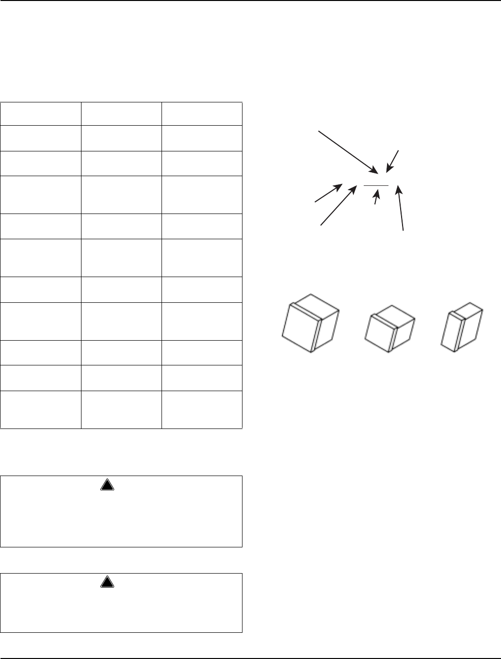
Ice Formation Pattern . . . . . . . . . . . . . . . . . . . . . . . . . . . . . . . . . . . . . . . . . 7-11
Safety Limits . . . . . . . . . . . . . . . . . . . . . . . . . . . . . . . . . . . . . . . . . . . . . . . . 7-13
Analyzing Discharge Pressure
During Freeze or Harvest Cycle . . . . . . . . . . . . . . . . . . . . . . . . . . . . . . . . . 7-16
Analyzing Suction Pressure
During Freeze Cycle . . . . . . . . . . . . . . . . . . . . . . . . . . . . . . . . . . . . . . . . . . 7-17
Single Expansion Valve Ice Machines -
Comparing Evaporator Inlet and Outlet Temperatures . . . . . . . . . . . . . . . . 7-19
Harvest Valve Temperature Check . . . . . . . . . . . . . . . . . . . . . . . . . . . . . . . 7-20
Discharge Line Temperature Analysis . . . . . . . . . . . . . . . . . . . . . . . . . . . . . 7-21
How to Use the Refrigeration System
Operational Analysis Tables . . . . . . . . . . . . . . . . . . . . . . . . . . . . . . . . . . . . 7-22
Refrigeration System Operational Analysis Tables . . . . . . . . . . . . . . . . . . . 7-23
Refrigeration System Operational Analysis Tables . . . . . . . . . . . . . . . . . . . 7-24
Harvest Pressure Regulating
(H.P.R.) System . . . . . . . . . . . . . . . . . . . . . . . . . . . . . . . . . . . . . . . . . . . . . . 7-25
Headmaster Control Valve . . . . . . . . . . . . . . . . . . . . . . . . . . . . . . . . . . . . . . 7-27
Pressure Control Specifications and Diagnostics . . . . . . . . . . . . . . . . . . . . . 7-29
Fan Cycle Control . . . . . . . . . . . . . . . . . . . . . . . . . . . . . . . . . . . . . . . . . . . . 7-29
High Pressure Cut-Out (HPCO) Control . . . . . . . . . . . . . . . . . . . . . . . . . . . 7-29
Cycle Time/24 Hour Ice Production/Refrigerant Pressure Charts . . . . . . . . . 7-30
S300 Series . . . . . . . . . . . . . . . . . . . . . . . . . . . . . . . . . . . . . . . . . . . . . . . . . 7-31
S320 Series . . . . . . . . . . . . . . . . . . . . . . . . . . . . . . . . . . . . . . . . . . . . . . . . . 7-32
S420 Series . . . . . . . . . . . . . . . . . . . . . . . . . . . . . . . . . . . . . . . . . . . . . . . . . 7-33
S450 Series . . . . . . . . . . . . . . . . . . . . . . . . . . . . . . . . . . . . . . . . . . . . . . . . . 7-34
S500 Series . . . . . . . . . . . . . . . . . . . . . . . . . . . . . . . . . . . . . . . . . . . . . . . . . 7-35
S600 Series . . . . . . . . . . . . . . . . . . . . . . . . . . . . . . . . . . . . . . . . . . . . . . . . . 7-36
S850 Series . . . . . . . . . . . . . . . . . . . . . . . . . . . . . . . . . . . . . . . . . . . . . . . . . 7-38
S1000 Series . . . . . . . . . . . . . . . . . . . . . . . . . . . . . . . . . . . . . . . . . . . . . . . . 7-39
S1400 Series . . . . . . . . . . . . . . . . . . . . . . . . . . . . . . . . . . . . . . . . . . . . . . . . 7-41
S1800 Series . . . . . . . . . . . . . . . . . . . . . . . . . . . . . . . . . . . . . . . . . . . . . . . . 7-42

Table of Contents (continued)
Part No. 80-1480-3 5
Refrigerant Recovery/Evacuation and Recharging . . . . . . . . . . . . . . . . . . . . 7-44
Normal Self-Contained Model Procedures . . . . . . . . . . . . . . . . . . . . . . . . . 7-44
Normal Remote Model Procedures . . . . . . . . . . . . . . . . . . . . . . . . . . . . . . . 7-46
System Contamination Clean-Up . . . . . . . . . . . . . . . . . . . . . . . . . . . . . . . . 7-50
Replacing Pressure Controls Without
Removing Refrigerant Charge . . . . . . . . . . . . . . . . . . . . . . . . . . . . . . . . . . 7-52
Filter-Driers . . . . . . . . . . . . . . . . . . . . . . . . . . . . . . . . . . . . . . . . . . . . . . . . . 7-54
Total System Refrigerant Charges . . . . . . . . . . . . . . . . . . . . . . . . . . . . . . . 7-55
Refrigerant Definitions . . . . . . . . . . . . . . . . . . . . . . . . . . . . . . . . . . . . . . . . 7-56
Refrigerant Re-Use Policy . . . . . . . . . . . . . . . . . . . . . . . . . . . . . . . . . . . . . 7-57
HFC Refrigerant Questions and Answers . . . . . . . . . . . . . . . . . . . . . . . . . . 7-58

Table of Contents (continued)
6Part No. 80-1480-3
Section 1 General Information
Part Number 80-1480-3 1-1
Section 1
General Information
Model Numbers
This manual covers the following models:
NOTE: Model numbers ending in 3 indicate a 3-phase
unit. Example: SY1004A3
How to Read a Model Number
Ice Cube Sizes
Self-Contained
Air-Cooled Self-Contained
Water-Cooled Remote
SD0302A
SY0304A
SD0303W
SY0305W
----
----
SD0322A
SY0324A
SD0323W
SY0325W
----
----
SR0420A
SD0422A
SY0424A
SR0421W
SD0423W
SY0425W
----
----
SD0452A
SY0454A
SD0453W
SY0455W
----
----
SR0500A
SD0502A
SY0504A
SR501W
SD0503W
SY0505W
SD0592N
SY0594N
SD0602A
SY0604A
SD0603W
SY0605W
SD0692N
SY0694N
SR0850A
SD0852A
SY0854A
SR0851W
SD0853W
SY0855W
SR0890N
SD0892N
SY0894N
SD1002A
SY1004A
SD1003W
SY1005W
SD1092N
SY1094N
SD1402A
SY1404A
SD1403W
SY1405W
SD1492N
SY1494N
SR1800A
SD1802A
SY1804A
SR1801W
SD1803W
SY1805W
SR1890N
SD1892N
SY1894N
!
Warning
PERSONAL INJURY POTENTIAL
Do not operate equipment that has been misused,
abused, neglected, damaged, or altered/modified
from that of original manufactured specifications.
!
Warning
PERSONAL INJURY POTENTIAL
Remove all ice machine panels before lifting and
installing.
Regular
1-1/8" x 1-1/8" x 7/8"
2.86 x 2.86 x 2.22 cm
Dice
7/8" x 7/8" x 7/8"
2.22 x 2.22 x 2.22 cm
Half Dice
3/8" x 1-1/8" x 7/8"
0.95 x 2.86 x 2.22 cm
S Y 1094 N
ICE MACHINE
MODEL
ICE CUBE SIZE
R REGULAR
D DICE
Y HALF DICE
# CUBE SIZE
0 REGULAR
1 REGULAR
2 DICE
3 DICE
4 HALF-DICE
5 HALF-DICE
CONDENSER TYPE
AIR-COOLED
WAT ER-COOLED
AIR-COOLED
WAT ER-COOLED
AIR-COOLED
WAT ER-COOLED
A SELF-CONTAINED AIR-COOLED
W SELF-CONTAINED WAT ER-COOLED
N REMOTE AIR-COOLED
9 REMOTE
AIR-COOLED
CONDENSER TYPE
ICE MACHINE
SERIES

General Information Section 1
1-2 Part Number 80-1480-3
Accessories
Contact your Manitowoc distributor for these optional
accessories:
BIN CASTER
Replaces standard legs.
ICE BAGGER
Maximize profits from bagged ice sales with this
convenient accessory. This sturdy unit rests on the bin
door frame, and adapts for left or right side filling.
GUARDIANf SACHET PACKETS
Guardian sachet packets release chlorine dioxide on a
controlled basis to inhibit the growth of bacteria and
slime.
Guardian sachet packets are available through your
local Manitowoc Ice Machine dealer.
ARCTIC PUREf WATER FILTER SYSTEM
Engineered specifically for Manitowoc ice machines,
This water filter is an efficient, dependable, and
affordable method of inhibiting scale formation, filtering
sediment, and removing chlorine taste and odor.
MANITOWOC CLEANER AND SANITIZER
Manitowoc Ice Machine Cleaner and Sanitizer are
available in convenient 16 oz. (473 ml) bottles. These
are the only cleaner and sanitizer approved for use with
Manitowoc products.
AUCS® AUTOMATIC CLEANING SYSTEM
This accessory reduces equipment cleaning expense.
The AuCS® accessory monitors ice making cycles and
initiates cleaning procedures automatically.
DISPENSER
A counter-top dispenser is ideal for cafeterias and many
types of self-service facilities. Manitowoc auto-fill, floor-
standing ice dispensers meet the strict sanitary
requirements of the food service, lodging and health
care industries.
Cleaner Part Number Sanitizer Part Number
16 ounce Bottle - 94-0546-3 16 ounce Bottle - 94-0565-3
AuCS®-SO - 94-0546-3 AuCS®-SO - 94-0565-3
AuCS®-SI - 40-1326-3 AuCS®-SI - 40-1327-3
Section 1 General Information
Part Number 80-1480-3 1-3
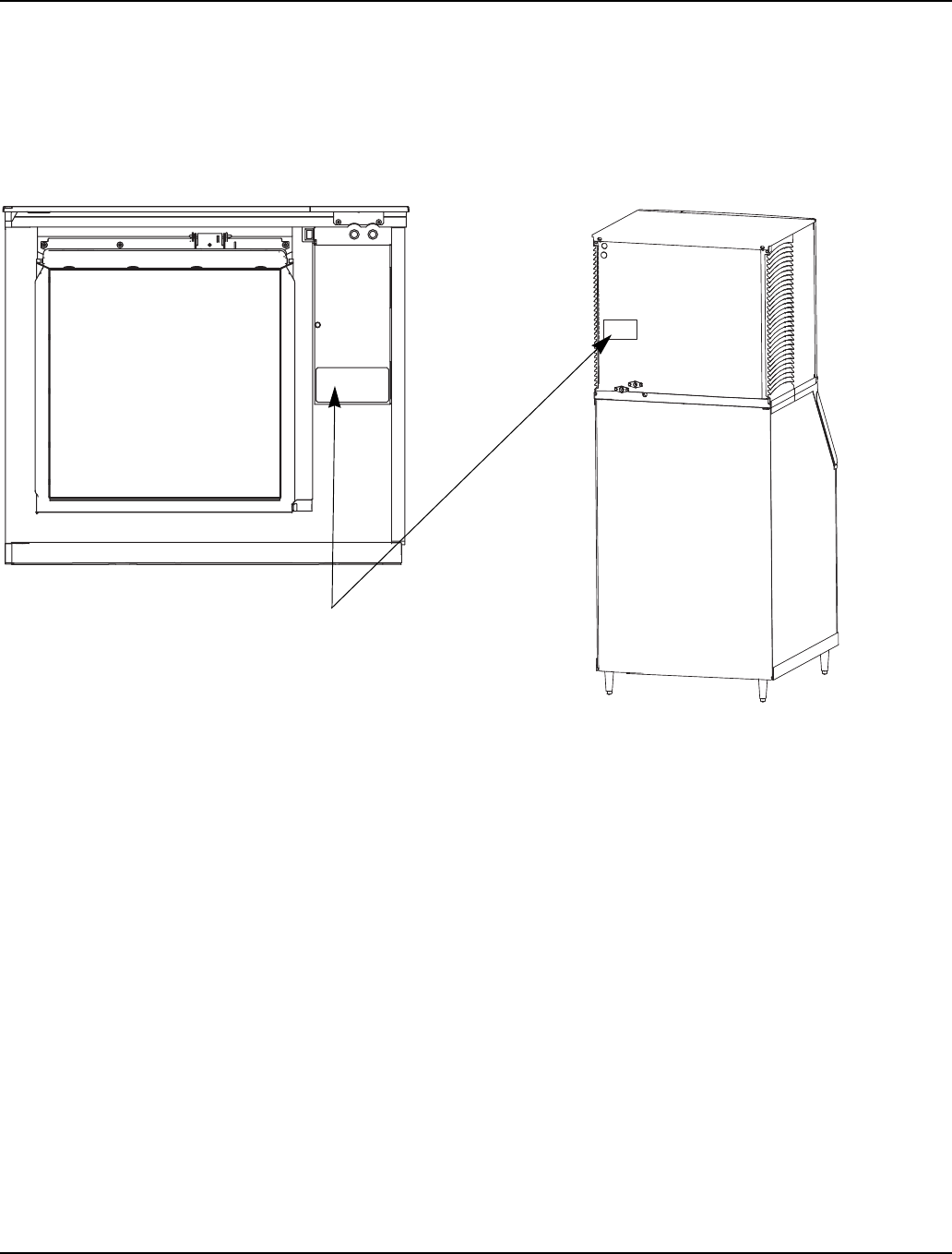
Model/Serial Number Location
These numbers are required when requesting
information from your local Manitowoc distributor, or
Manitowoc Ice, Inc.
The model and serial number are listed on the MODEL/
SERIAL NUMBER DECAL affixed to the ice machine,
remote condenser and storage bin.
Model/Serial Number Location
SV13147
MODEL/SERIAL DECAL
LOCATION

General Information Section 1
1-4 Part Number 80-1480-3
Owner Warranty Registration Card
GENERAL
The packet containing this manual also includes
warranty information. Warranty coverage begins the day
your new ice machine is installed.
If you do not return your OWNER WARRANTY
REGISTRATION CARD, Manitowoc will use the date of
sale to the Manitowoc Distributor as the first day of
warranty coverage for your new ice machine.
Warranty Coverage
GENERAL
The following Warranty outline is provided for your
convenience. For a detailed explanation, read the
warranty bond shipped with each product.
Contact your local Manitowoc Distributor, Manitowoc Ice,
Inc. or visit our website at www.manitowocice.com if you
need further warranty information.
PARTS
1. Manitowoc warrants the ice machine against defects
in materials and workmanship, under normal use
and service for three (3) years from the date of
original installation.
2. The evaporator and compressor are covered by an
additional two (2) year (five years total) warranty
beginning on the date of the original installation.
LABOR
1. Labor required to repair or replace defective
components is covered for three (3) years from the
date of original installation.
2. The evaporator is covered by an additional two (2)
year (five years total) labor warranty beginning on
the date of the original installation.
EXCLUSIONS
The following items are not included in the ice machine’s
warranty coverage:
1. Normal maintenance, adjustments and cleaning.
2. Repairs due to unauthorized modifications to the
ice machine or use of non-standard parts without
prior written approval from Manitowoc Ice, Inc.
3. Damage caused by improper installation of the ice
machine, electrical supply, water supply or drainage,
or damage caused by floods, storms, or other acts of
God.
4. Premium labor rates due to holidays, overtime,
etc.; travel time; flat rate service call charges;
mileage and miscellaneous tools and material
charges not listed on the payment schedule.
Additional labor charges resulting from the
inaccessibility of equipment are also excluded.
5. Parts or assemblies subjected to misuse, abuse,
neglect or accidents.
6. Damage or problems caused by installation,
cleaning and/or maintenance procedures
inconsistent with the technical instructions
provided in this manual.
7. This product is intended exclusively for
commercial application. No warranty is extended
for personal, family, or household purposes.
AUTHORIZED WARRANTY SERVICE
To comply with the provisions of the warranty, a
refrigeration service company qualified and
authorized by a Manitowoc distributor, or a
Contracted Service Representative must perform the
warranty repair.
NOTE: If the dealer you purchased the ice machine from
is not authorized to perform warranty service, contact
your Manitowoc distributor or Manitowoc Ice, Inc. for the
name of the nearest authorized service representative.
Service Calls
Normal maintenance, adjustments and cleaning as
outlined in this manual are not covered by the
warranty. If you have followed the procedures listed on
page 5-1 of this manual, and the ice machine still does
not perform properly, call your authorized service
company.
Important
Complete and mail the OWNER WARRANTY
REGISTARATION CARD as soon as possible to
validate the installation date.
Important
This product is intended exclusively for commercial
application. No warranty is extended for personal,
family, or household purposes.
Section 2 Installation Instructions
Part Number 80-1480-3 2-1
Section 2
Installation Instructions
General
These instructions are provided to assist the qualified
installer. Check your local Yellow Pages for the name of
the nearest Manitowoc distributor, or call Manitowoc Ice,
Inc. for information regarding start-up services.
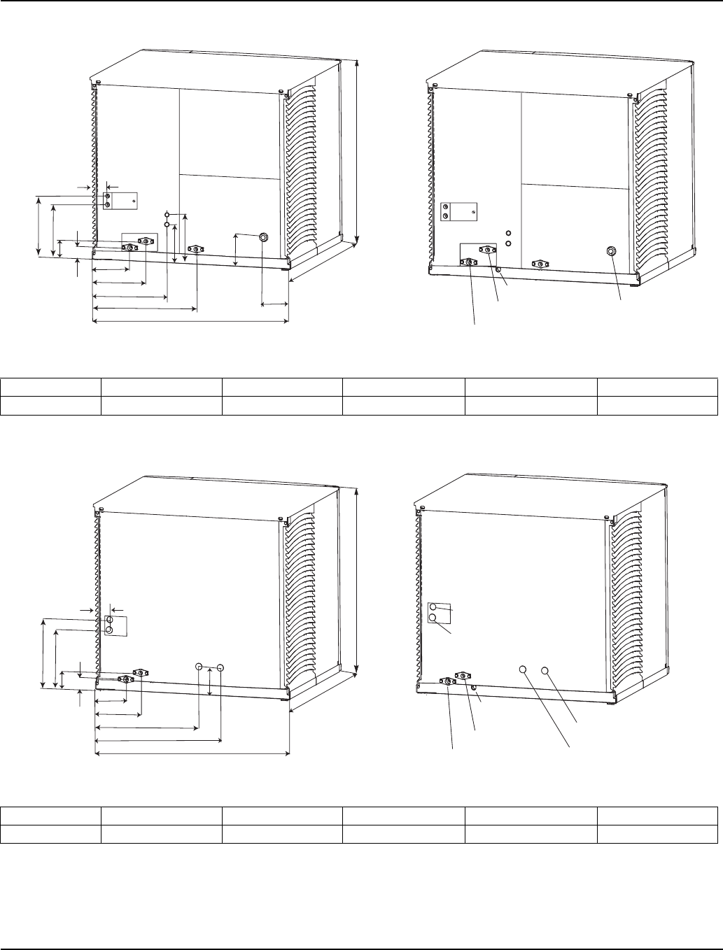
Ice Machine Dimensions
S320/S420 AIR AND WATER-COOLED ICE MACHINES
Important
Failure to follow these installation guidelines may
affect warranty coverage.
2.20" (5.58cm)
H
D
W
6.68" (16.96cm)
5.06" (12.85cm)
1.1" (2.6cm)
1.8"
(4.6cm)
2.6"
(6.6cm)
19.3"
(49.0 cm)
5.0" (12.7cm)
17.0" (43.2cm)
8.49" (21.56cm)
2.85" (7.30cm)
4.21" (10.69cm)
4" (10cm)
3.25" (8.3cm)
ELECTRICAL
AUCS
TUBING &
MODULAR
WIRE
DRAIN 1/2"NPTF
WATER INLET
3/8"FPT
CONDENSER WATER
OUTLET 1/2"FPT
(Water-Cooled Only)
CONDENSER WATER
INLET 3/8"FPT
(Water-Cooled Only)
AUXILLARY BASE DRAIN
1/2"CPVC SOCKET
AUCS
ELECTRICAL
Ice Machine Dimension W Dimension D Dimension H
S320 22 in. (55.9 cm) 24.5 in. (62.2 cm) 21.5 in (54.6 cm)
S420 22 in. (55.9 cm) 24.5 in. (62.2 cm) 21.5 in (54.6 cm)
Installation Instructions Section 2
2-2 Part Number 80-1480-3
S600 AIR AND WATER-COOLED ICE MACHINES
S600 REMOTE ICE MACHINES
Ice Machine Dimension A Dimension B Dimension W Dimension D Dimension H
S600 11.5 in (29.2 cm) 9.0 in (22.9 cm) 30 in. (76.2 cm) 24.50 in. (62.2 cm) 21.5 in (54.6 cm)
Ice Machine Dimension A Dimension B Dimension W Dimension D Dimension H
S600 11.5 in (29.2 cm) 9.0 in (22.9 cm) 30 in. (76.2 cm) 24.50 in. (62.2 cm) 21.5 in (54.6 cm)
1.50" (3.81cm)
H
D
W
4.25" (10.81 cm)
17.25" (43.81 cm)
6.68" (16.96cm)
5.06" (12.85cm)
2.85" (7.30cm)
1.81"
(4.59cm)
2.61"
(6.62cm)
A
B
6.50" (16.5cm)
8.50" (21.60cm)
7.75" (19.7 cm)
ELECTRICAL
AUCS
CONNECTIONS
DRAIN 1/2"NPTF
WATER INLET
3/8"FPT
CONDENSER WATER
OUTLET 1/2"FPT
(Water-Cooled Only)
CONDENSER WATER
INLET 3/8"FPT
(Water-Cooled Only)
AUXILLARY BASE DRAIN
1/2"CPVC SOCKET
1.50" (3.81cm)
H
D
W
16.0" (40.64cm)
11.50" (29.21cm)
6.68" (16.96cm)
5.06" (12.85cm)
6.25" (15.88cm)
1.81"
(4.59cm)
2.61"
(6.62cm)
AB
ELECTRICAL
REMOTE CONDENSER
ELECTRICAL
DRAIN 1/2"NPTF
WATER INLET
3/8"FPT
REFRIGERANT
LIQUID LINE
REFRIGERANT
DISCHARGE LINE
AUXILLARY BASE
DRAIN 1/2"CPVC
SOCKET
Section 2 Installation Instructions
Part Number 80-1480-3 2-3
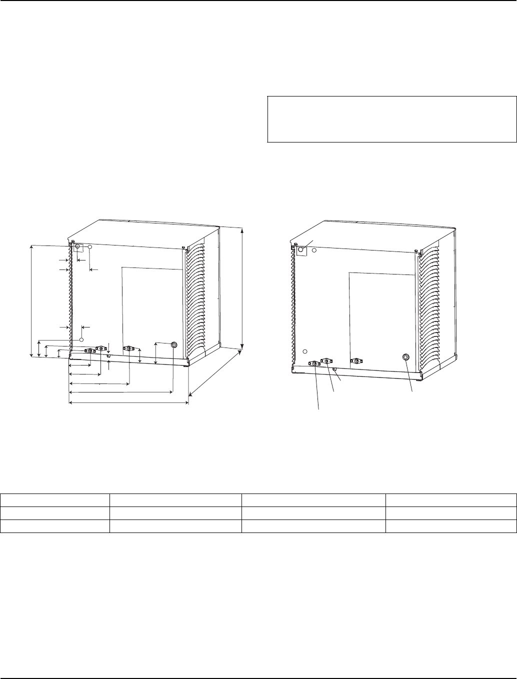
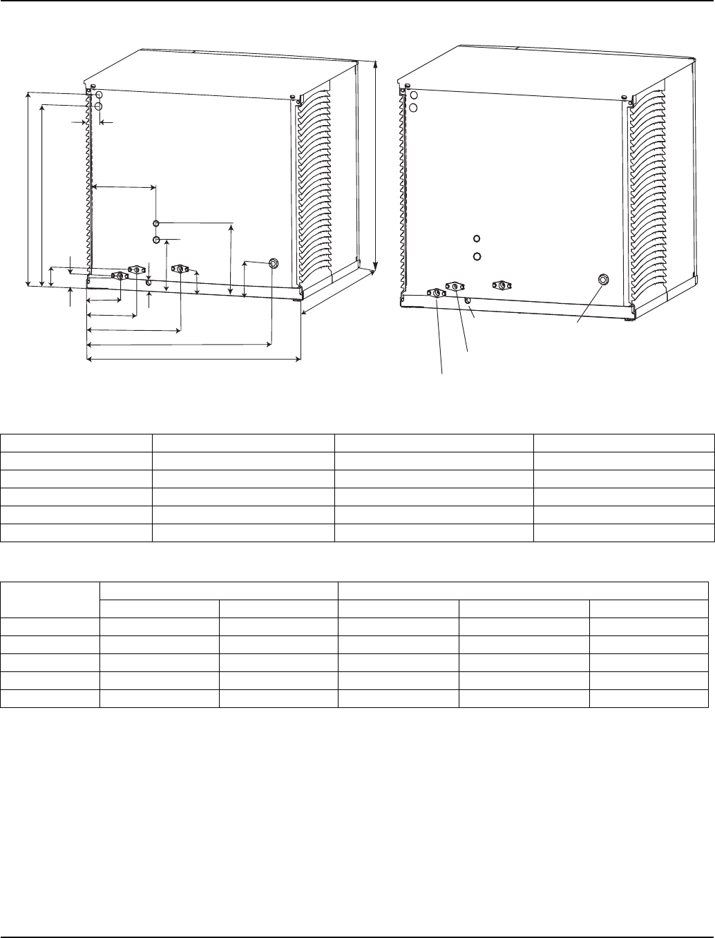
S300/S450/S500/S850/S1000 AIR AND WATER-COOLED ICE MACHINES
Width, Depth, and Height Dimensions
Electrical and AuCS Dimensions
ELECTRICAL
DRAIN 1/2"NPTF
WATER INLET
3/8"FPT
CONDENSER WATER
OUTLET 1/2"FPT
(Water-Cooled Only)
CONDENSER WATER
INLET 3/8"FPT
(Water-Cooled Only)
AUXILLARY BASE
DRAIN 1/2"CPVC
SOCKET
AUCS
CONNECTIONS
2.20" (5.58cm)
H
D
W
25.52" (64.82cm)
8.49" (21.56cm)
6.68" (16.96cm)
5.06" (12.85cm)
1.06 (2.7cm)
2.85" (7.30cm)
4.21" (10.69cm)
1.81"
(4.59cm)
2.61"
(6.62cm)
A
BC
E
F
SV3143
SV3143B
Ice Machine Dimension W Dimension D Dimension H
S300 30 in. (76.2 cm) 24.50 in. (62.2 cm) 16.5 in (41.9 cm)
S450 30 in. (76.2 cm) 24.50 in. (62.2 cm) 21.5 in (54.6 cm)
S500 30 in. (76.2 cm) 24.50 in. (62.2 cm) 21.5 in (54.6 cm)
S850 30 in. (76.2 cm) 24.50 in. (62.2 cm) 26.5 in (67.3 cm)
S1000 30 in. (76.2 cm) 24.50 in. (62.2 cm) 26.5 in (67.3 cm)
Ice Machine Electrical AuCS
Dimension A Dimension B Dimension C Dimension E Dimension F
S300 14.00 in (35.6 cm) NA 10.0 in (25.4 cm) 6.0 in (15.24 cm) 4.0 in (10.16 cm)
S450 19.25 in (48.9 cm) 17.5 in (44.45 cm) 8.5 in (21.6 cm) 8.5 in (21.6 cm) 6.5 in (16.5 cm)
S500 19.25 in (48.9 cm) 17.5 in (44.45 cm) 8.5 in (21.6 cm) 8.5 in (21.6 cm) 6.5 in (16.5 cm)
S850 23.82 in (60.5 cm) 22.32 in (56.69 cm) 8.5 in (21.6 cm) 8.5 in (21.6 cm) 6.5 in (16.5 cm)
S1000 23.82 in (60.5 cm) 22.32 in (56.69 cm) 8.5 in (21.6 cm) 8.5 in (21.6 cm) 6.5 in (16.5 cm)
Installation Instructions Section 2
2-4 Part Number 80-1480-3
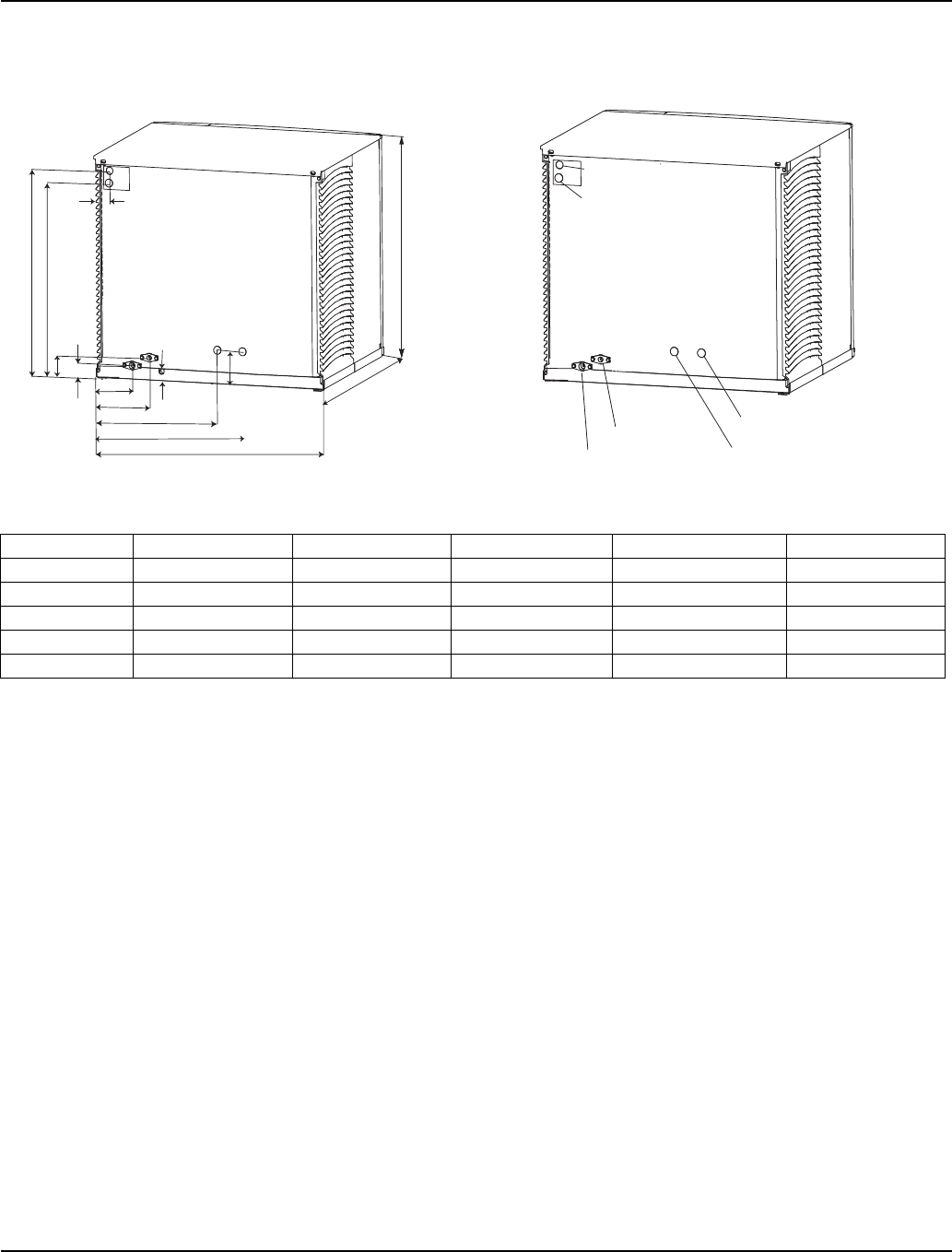
S500/S850/S1000 REMOTE ICE MACHINES
2.20" (5.58cm)
H
D
W
16.64" (64.82cm)
12.26" (42.27cm)
6.68" (16.96cm)
5.06" (12.85cm)
1.06 (2.69cm) 6.12" (15.54cm)
1.81"
(4.59cm)
2.61"
(6.62cm)
A
B
SV3146 SV3146B
DRAIN 1/2"NPTF
WATER INLET
3/8"FPT
REFRIGERANT
LIQUID LINE
REFRIGERANT
DISCHARGE LINE
ELECTRICAL
REMOTE CONDENSER
ELECTRICAL
Ice Machine Dimension A Dimension B Dimension W Dimension D Dimension H
S300 14.00 in (35.6 cm) NA 30 in. (76.2 cm) 24.50 in. (62.2 cm) 16.5 in (41.9 cm)
S450 19.25 in (48.9 cm) 17.5 in (44.45 cm) 30 in. (76.2 cm) 24.50 in. (62.2 cm) 21.5 in (54.6 cm)
S500 19.25 in (48.9 cm) 17.5 in (44.45 cm) 30 in. (76.2 cm) 24.50 in. (62.2 cm) 21.5 in (54.6 cm)
S850 23.82 in (60.5 cm) 22.32 in (56.69 cm) 30 in. (76.2 cm) 24.50 in. (62.2 cm) 26.5 in (67.3 cm)
S1000 23.82 in (60.5 cm) 22.32 in (56.69 cm) 30 in. (76.2 cm) 24.50 in. (62.2 cm) 26.5 in (67.3 cm)
Section 2 Installation Instructions
Part Number 80-1480-3 2-5
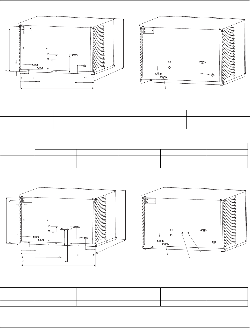
S1400 / S1800 AIR AND WATER-COOLED ICE MACHINES
Width, Depth, and Height Dimensions
Electrical and AuCS Dimensions
S1400 / S1800 REMOTE ICE MACHINES
2.50" (6.35cm)
H
D
W
11.0" (27.9cm)
10.25" (26.0cm)
2.0" (5.1cm)
5.75" (14.6cm)
4.0"
(10.2cm)
A
B
3.0" (7.6cm)
3.75" (9.5cm)
11.0" (27.9cm)
7.8" (19.8cm)
1.1" (2.8cm)
C
E
F
ELECTRICAL
CONDENSER WATER
OUTLET 1/2"FPT
(Water-Cooled Only)
DRAIN 1/2"NPTF
CONDENSER WATER
INLET 3/8"FPT
(Water-Cooled Only)
AUXILLARY BASE DRAIN
1/2"CPVC SOCKET
WATER INLET
3/8"FPT
AuCS
Connections
Ice Machine Dimension W Dimension D Dimension H
S1400 48 in. (121.9 cm) 24.5 in. (62.2 cm) 29.5 in (74.9 cm)
S1800 48 in. (121.9 cm) 24.5 in. (62.2 cm) 29.5 in (74.9 cm)
Ice Machine Electrical AuCS
Dimension A Dimension B Dimension C Dimension E Dimension F
S1400 22.75 in (57.8 cm) 22.25 in (56.5 cm) 14.0 in (35.6 cm) 9.5 in (24.1 cm) 7.5 in (19.1 cm)
S1800 22.75 in (57.8 cm) 22.25 in (56.5 cm) 14.0 in (35.6 cm) 9.5 in (24.1 cm) 7.5 in (19.1 cm)
2.50" (6.35cm)
H
D
W
11.0" (27.9cm)
10.25" (26.0cm)
2.0" (5.1cm)
5.75" (14.6cm)
4.0"
(10.2cm)
A
B
3.0" (7.6cm)
3.75" (9.5cm)
11.0" (27.9cm)
7.8" (19.8cm)
1.1" (2.8cm)
C
E
F
8.0"
(20.3cm)
23.75" (60.3cm)
28.25" (71.8cm)
ELECTRICAL
CONDENSER WATER
OUTLET 1/2"FPT
(Water-Cooled Only)
DRAIN 1/2"NPTF
CONDENSER WATER
INLET 3/8"FPT
(Water-Cooled Only)
AUXILLARY BASE DRAIN
1/2"CPVC SOCKET
WATER INLET
3/8"FPT
AuCS
Connections
REFRIGERANT
LIQUID LINE
REFRIGERANT
DISCHARGE LINE
Ice Machine Dimension A Dimension B Dimension W Dimension D Dimension H
S1400 22.75 in (57.8 cm) 22.25 in (56.5 cm) 48 in. (121.9 cm) 24.5 in. (62.2 cm) 29.5 in (74.9 cm)
S1800 22.75 in (57.8 cm) 22.25 in (56.5 cm) 48 in. (121.9 cm) 24.5 in. (62.2 cm) 29.5 in (74.9 cm)
Installation Instructions Section 2
2-6 Part Number 80-1480-3
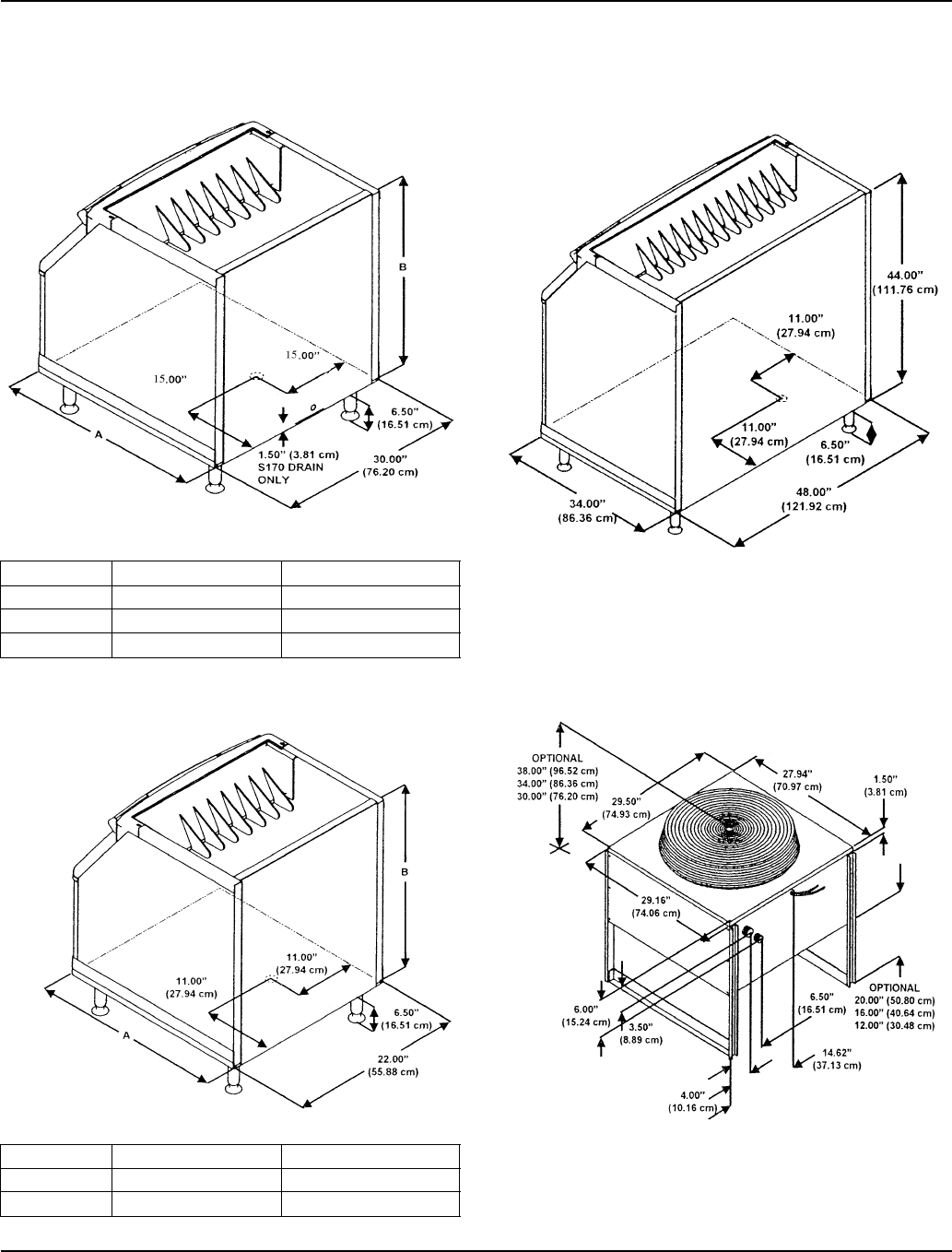
Ice Storage Bin Dimensions
30 INCH (76 CM) ICE STORAGE BINS
22 INCH (56 CM) ICE STORAGE BINS
48 INCH (130 CM) ICE STORAGE BINS
Remote Condenser Dimensions
JC0495/JC0895/JC1395
Bin Model Dimension A Dimension B
B170 29.5 in (74.9 cm) 19.1 in (48.5 cm)
B420 34.0 in (86.3 cm) 32.0 in (81.3 cm)
B570 34.0 in (86.3 cm) 44.0 in (111.7 cm)
Bin Model Dimension A Dimension B
B320 34.0 in (86.3 cm) 32.0 in (81.3 cm)
B420 34.0 in (86.3 cm) 44.0 in (111.7 cm)
SV1609
SV1614
SV1297
B970
SV1297
Section 2 Installation Instructions
Part Number 80-1480-3 2-7
Location of Ice Machine
The location selected for the ice machine must meet the
following criteria. If any of these criteria are not met,
select another location.
• The location must be free of airborne and other
contaminants.
• The air temperature must be at least 35°F (1.6°C),
but must not exceed 110°F (43.4°C).
• Remote air cooled - The air temperature must be at
least -20°F (-29°C), but must not exceed 120°F
(49°C)
• The location must not be near heat-generating
equipment or in direct sunlight and must be protected
from weather.
• The location must not obstruct air flow through or
around the ice machine. Refer to the chart below for
clearance requirements.
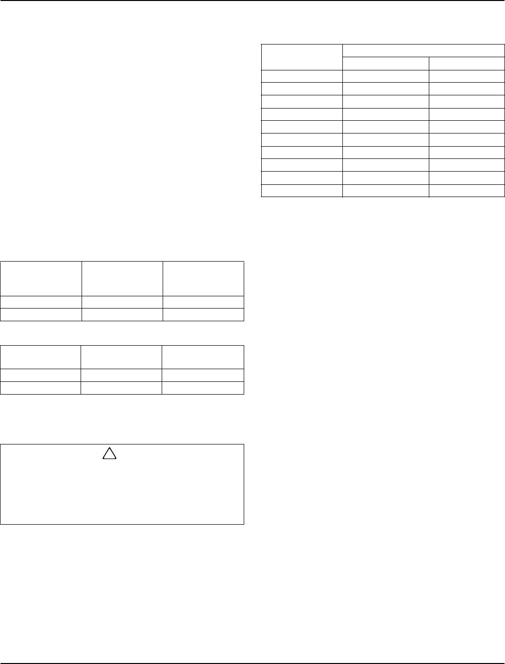
Ice Machine Heat of Rejection
Ice machines, like other refrigeration equipment, reject
heat through the condenser. It is helpful to know the
amount of heat rejected by the ice machine when sizing
air conditioning equipment where self-contained air-
cooled ice machines are installed.
This information is also necessary when evaluating the
benefits of using water-cooled or remote condensers to
reduce air conditioning loads. The amount of heat added
to an air conditioned environment by an ice machine
using a water-cooled or remote condenser is negligible.
Knowing the amount of heat rejected is also important
when sizing a cooling tower for a water-cooled
condenser. Use the peak figure for sizing the cooling
tower.
S300 / S320/
S420/ S450/S500/
S600/S850/S1000
Self-Contained
Air-Cooled Water-Cooled
and Remote*
Top/Sides 8" (20.3 cm) 8" (20.3 cm)
Back 5" (12.7 cm) 5" (12.7 cm)
S1400/S1800 Self-Contained
Air-Cooled Water-Cooled
and Remote*
Top/Sides 24" (61.0 cm) 8" (20.3 cm)
Back 12" (30.5 cm) 5" (12.7 cm)
*There is no minimum clearance required for water-cooled or
remote ice machines. This value is recommended for efficient
operation and servicing only.
!
Caution
The ice machine must be protected if it will be
subjected to temperatures below 32°F (0°C).
Failure caused by exposure to freezing
temperatures is not covered by the warranty. See
“Removal from Service/Winterization”.
Series
Ice Machine
Heat of Rejection
B.T.U./Hour
Air Conditioning
Because the heat of rejection varies during the ice making cycle,
the figure shown is an average.
Peak
S300 3800 6000
S320 3800 6000
S420 7000 9600
S450 7000 9600
S500 7000 9600
S600 9000 13900
S850 12000 18000
S1000 16000 22000
S1400 19000 28000
S1800 24000 36000
Installation Instructions Section 2
2-8 Part Number 80-1480-3
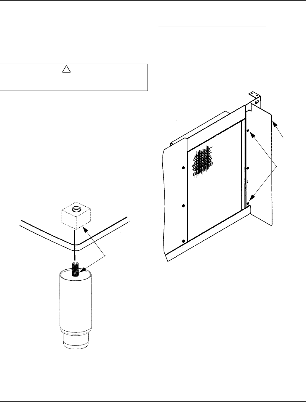
Removing Drain Plug and Leveling the Ice
Storage Bin
1. Remove threaded plug from drain fitting.
2. Screw the leveling legs onto the bottom of the bin.
3. Screw the foot of each leg in as far as possible.
4. Move the bin into its final position.
5. Level the bin to assure that the bin door closes and
seals properly. Use a level on top of the bin. Turn the
base of each foot as necessary to level the bin.
6. Inspect bin gasket prior to ice machine installation.
(Manitowoc bins come with a closed cell foam
gasket installed along the top surface of the bin.)
7. Remove all panels from ice machine before lifting.
Remove both front panels, top cover, left and right
side panels.
8. Install ice machine on bin.
Leveling Leg and Foot
Air-Cooled Baffle
SELF-CONTAINED AIR-COOLED ONLY
The air-cooled baffle prevents condenser air from
recirculating. To install:
1. Remove the back panel screws next to the
condenser.
2. Align the mounting holes in the air baffle with the
screw holes and reinstall the screws.
Air Baffle
!
Caution
The legs must be screwed in tightly to prevent them
from bending.
SV1606
THREAD LEVELING
LEG INTO BASE OF
CABINET
SV1607
AIR
BAFFLE
SCREWS
Section 2 Installation Instructions
Part Number 80-1480-3 2-9
Electrical Service
GENERAL
VOLTAGE
The maximum allowable voltage variation is ±10% of the
rated voltage at ice machine start-up (when the electrical
load is highest).
Fuse/Circuit Breaker
A separate fuse/circuit breaker must be provided for
each ice machine. Circuit breakers must be H.A.C.R.
rated (does not apply in Canada).
MINIMUM CIRCUIT AMPACITY
The minimum circuit ampacity is used to help select the
wire size of the electrical supply. (Minimum circuit
ampacity is not the ice machine’s running amp load.)
The wire size (or gauge) is also dependent upon
location, materials used, length of run, etc., so it must be
determined by a qualified electrician.
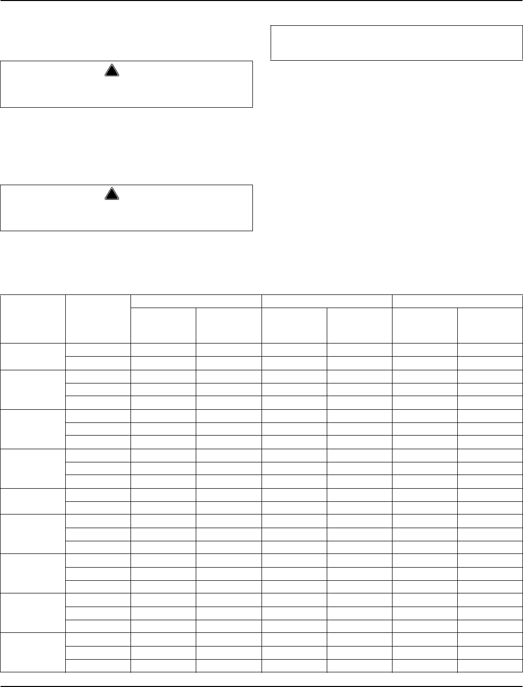
ELECTRICAL REQUIREMENTS
Refer to Ice Machine Model/Serial Plate for voltage/
amperage specifications.
S Series Ice Machines (* indicates preliminary data)
!
Warning
All wiring must conform to local, state and national
codes.
!
Warning
The ice machine must be grounded in accordance
with national and local electrical codes.
Important
Observe correct polarity of incoming line voltage.
Ice Machine Voltage
Phase
Cycle
Air-Cooled Water Cooled Remote
Maximum
Fuse/Circuit
Breaker
Minimum
Circuit Amps
Maximum
Fuse/Circuit
Breaker
Minimum
Circuit Amps
Maximum
Fuse/Circuit
Breaker
Minimum
Circuit Amps
S300 115/1/60 20 12.9 20 12.1 N/A N/A
230/1/50 15 6.4 15 5.9 N/A N/A
S320
115/1/60 15 11.3 15 10.5 N/A N/A
208-230/1/60 15 6.0 15 5.6 N/A N/A
230/1/50 15 6.0 15 5.6 N/A N/A
S420/S450
115/1/60 20 13.6 20 12.9 N/A N/A
208-230/1/60 15 6.3 15 5.9 N/A N/A
230/1/50 15 6.7 15 6.4 N/A N/A
S500
115/1/60 20 13.0 20 12.3 20 14.1
208-230/1/60 15 7.3 15 6.9 N/A N/A
230/1/50 15 6.5 15 5.9 N/A N/A
S600 208-230/1/60 15 8.3 15 7.9 15 8.9
230/1/50 15 6.7 15 6.1 15 7.1
S850
208-230/1/60 20 11.3 20 10.3 20 10.6
208-230/3/60 15 7.8 15 6.8 15 7.8
230/1/50 20 10.5 20 9.1 20 9.7
S1000
208-230/1/60 20 13.6 20 12.6 20 12.8
208-230/3/60 15 9.9 15 8.9 15 9.9
230/1/50 20 12.6 20 11.2 20 12.0
S1400
208-230/1/60 30 17.5 30 16.1 30 17.1
208-230/3/60 20 13.2 20 11.8 20 12.8
230/1/50 30 15.1 30 13.7 30 14.7
S1800
208-230/1/60 40 23.5 40 22.1 40 23.1
208-230/3/60 20 13.4 20 12.0 20 13.0
230/1/50 40 21.9 40 20.5 40 21.5
Installation Instructions Section 2
2-10 Part Number 80-1480-3
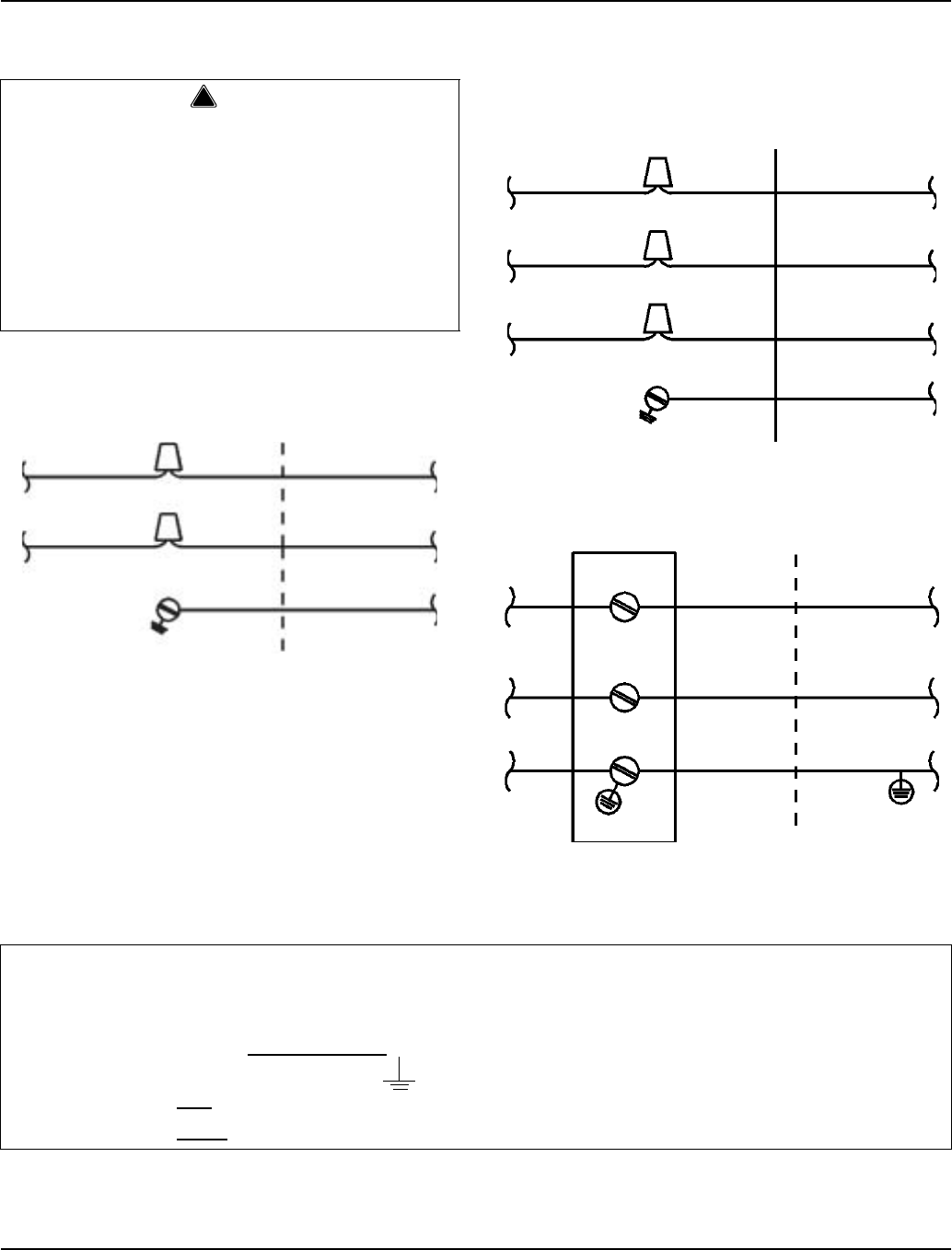
Self-Contained Electrical Wiring Connections
SELF CONTAINED ICE MACHINE
115/1/60 OR 208-230/1/60
SELF CONTAINED ICE MACHINE
208-230/3/60
SELF CONTAINED ICE MACHINE
230/1/50
!
Warning
These diagrams are not intended to show proper
wire routing, wire sizing, disconnects, etc., only the
correct wire connections.
All electrical work, including wire routing and
grounding, must conform to local, state and national
electrical codes.
Though wire nuts are shown in the drawings, the ice
machine field wiring connections may use either
wire nuts or screw terminals.
L1L1
N=115V
OR
L2=208-230V
GROUND
GROUND
ICE MACHINE
CONNECTIONS
SV1258 TO SEPARATE
FUSE/BREAKER
L1L1
GROUND
GROUND
ICE MACHINE
CONNECTIONS TO SEPARATE
FUSE/BREAKER
L2
L3
L2
L3
SV1190
L1L1
NN
GROUND GROUND
ICE MACHINE
CONNECTIONS
TO SEPARATE
FUSE/BREAKER.
DISCONNECT ALL
POLES.
SV1191
For United Kingdom Only
As the colors of the wires in the mains lead of the appliance may not correspond with the colored markings
identifying the terminals in your plug, proceed as follows:
• The wire which is colored green and yellow must be connected to the terminal in the plug which is marked with
the letter E or by the earth ground symbol or colored green or green and yellow.
• The wire colored blue must be connected to the terminal which is marked with the letter N or colored black.
• The wire colored brown must be connected to the terminal which is marked with the letter L or colored red.
Section 2 Installation Instructions
Part Number 80-1480-3 2-11
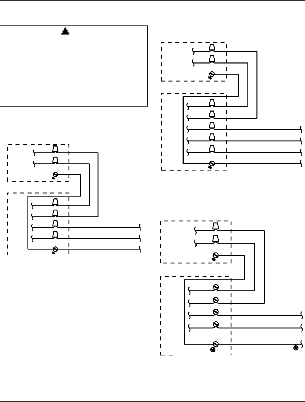
Remote Electrical Wiring Connections
REMOTE ICE MACHINE
WITH SINGLE CIRCUIT MODEL CONDENSER
115/1/60 OR 208-230/1/60
REMOTE ICE MACHINE
WITH SINGLE CIRCUIT MODEL CONDENSER
208-230/3/60 OR 380-415/3/50
REMOTE ICE MACHINE
WITH SINGLE CIRCUIT MODEL CONDENSER
230/1/50
!
Warning
These diagrams are not intended to show proper
wire routing, wire sizing, disconnects, etc., only the
correct wire connections.
All electrical work, including wire routing and
grounding, must conform to local, state and national
electrical codes.
Though wire nuts are shown in the drawings, the ice
machine field wiring connections may use either
wire nuts or screw terminals.
L1
NOTE:
CONDENSER FAN
MOTOR VOLTAGE
MATCHES ICE
MACHINE
VOLTAGE (115V
OR 208-230V)
GROUND
SINGLE
CIRCUIT
REMOTE
CONDENSER
ICE
MACHINE
SV1255
L2
L1
L2
GROUND
TO SEPARATE
FUSE/BREAKER
GROUND
L1
L2
F2
F1
N=115V OR L2=208-230V
GROUND
ICE
MACHINE
SV1199
L3
L1
L2
GROUND
TO SEPARATE
FUSE/BREAKER
GROUND
L3
L1
L2
F2
F1
NOTE: FAN
MOTOR IS
208-230V
L1
L2
SINGLE
CIRCUIT
REMOTE
CONDENSER
SINGLE CIRCUIT
REMOTE
CONDENSER
L1
L2NOTE: FAN
MOTOR IS
220-240V
L1
N
F2
F1
ICE
MACHINE
GROUND
L1
N
GROUND
TO SEPARATE
FUSE/BREAKER
(220-240).
DISCONNECT ALL
POLES.
SV1256

Installation Instructions Section 2
2-12 Part Number 80-1480-3
Water Supply and Drain Requirements
WATER SUPPLY
Local water conditions may require treatment of the
water to inhibit scale formation, filter sediment, and
remove chlorine odor and taste.
WATER INLET LINES
Follow these guidelines to install water inlet lines:
• Do not connect the ice machine to a hot water
supply. Be sure all hot water restrictors installed for
other equipment are working. (Check valves on sink
faucets, dishwashers, etc.)
• If water pressure exceeds the maximum
recommended pressure, obtain a water pressure
regulator from your Manitowoc distributor.
• Install a water shut-off valve for both the ice making
and condenser water lines.
• Insulate water inlet lines to prevent condensation.
DRAIN CONNECTIONS
Follow these guidelines when installing drain lines to
prevent drain water from flowing back into the ice
machine and storage bin:
• Drain lines must have a 1.5 inch drop per 5 feet of
run (2.5 cm per meter), and must not create traps.
• The floor drain must be large enough to
accommodate drainage from all drains.
• Run separate bin and ice machine drain lines.
Insulate them to prevent condensation.
• Vent the bin and ice machine drain to the
atmosphere. Do not vent the condenser drain on
water-cooled models.
Cooling Tower Applications
(Water-Cooled Models)
A water cooling tower installation does not require
modification of the ice machine. The water regulator
valve for the condenser continues to control the
refrigeration discharge pressure.
It is necessary to know the amount of heat rejection, and
the pressure drop through the condenser and water
valves (inlet and outlet) when using a cooling tower on
an ice machine.
• Water entering the condenser must not exceed 90°F
(32.2°C).
• Water flow through the condenser must not exceed 5
gallons (19 liters) per minute.
• Allow for a pressure drop of 7 psi (48 kPA) between
the condenser water inlet and the outlet of the ice
machine.
• Water exiting the condenser must not exceed 110°F
(43.3°C).
Important
If you are installing a Manitowoc Arctic Puref water
filter system, refer to the Installation Instructions
supplied with the filter system for ice making water
inlet connections.
!
Caution
Do not apply heat to water valve inlet fitting. This will
damage plastic valve body.
Section 2 Installation Instructions
Part Number 80-1480-3 2-13
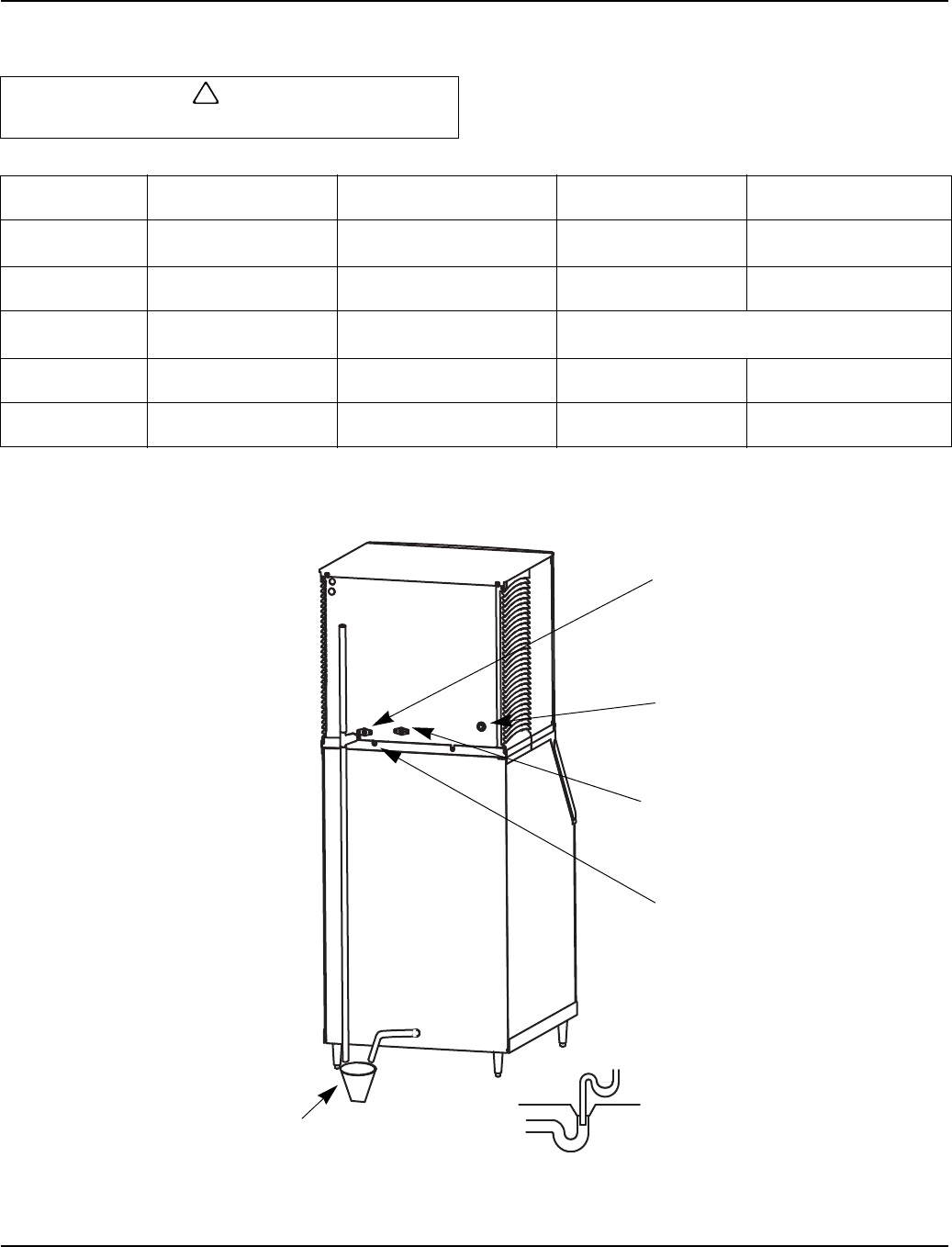
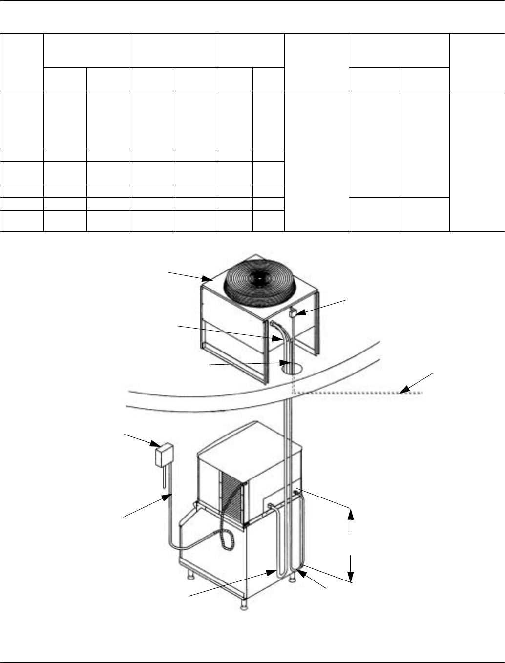
WATER SUPPLY AND DRAIN LINE SIZING/CONNECTIONS
Typical Water Supply Drain Installation
!
Caution
Plumbing must conform to state and local codes.
Location Water Temperature Water Pressure Ice Machine Fitting Tubing Size Up to Ice
Machine Fitting
Ice Making
Water Inlet
35°F (1.6°C) Min.
90°F (32.2°C) Max.
20 psi (137.9 kPA) Min.
80 psi (551.5 kPA) Max.
3/8" Female Pipe
Thread
3/8" (.95 cm) minimum
inside diameter
Ice Making
Water Drain --- --- 1/2" Female
Pipe Thread 1/2" (1.27 cm) minimum
inside diameter
Condenser
Water Inlet
40°F (4.4°C) Min.
90°F (32.2°C) Max.
20 psi (137.9 kPA) Min.
150 psi (1034.2 kPA) Max. 3/8" Female Pipe Thread
Condenser
Water Drain --- --- 1/2" Female
Pipe Thread 1/2" (1.27 cm) minimum
inside diameter
Bin Drain --- --- 3/4" Female
Pipe Thread 3/4" (1.91 cm) minimum
inside diameter
SV3142
ELECTRICAL ENTRANCE
18” (46 CM) VENT TUBE
AIR GAP
1/2” (1.3 CM) MIN
DRAIN ID
1/2” DRAIN CONNECTION
PLASTIC FITTING ON OPPOSITE
SIDE DO NOT APPLY HEAT
OPEN, TRAPPED AND
VENTED DRAIN
DO NOT TRAP DRAIN LINE,
LEAVE AIR GAP BETWEEN
DRAIN TUBE AND DRAIN
3/8” FPT ICE MAKING WATER INLET FITTING,
PLASTIC FITTING ON OPPOSITE SIDE DO NOT
APPLY HEAT
1/2” FPT CONDENSER WATER DRAIN
(WATER COOLED UNITS ONLY)
3/8” FPT CONDENSER WATER INLET
(WATER COOLED UNITS ONLY
1/2” CPVC SOCKET AUXILLARY BASE
DRAIN
Installation Instructions Section 2
2-14 Part Number 80-1480-3
Remote Condenser/Line Set Installation
REMOTE ICE MACHINES
REFRIGERANT CHARGE
Each remote ice machine ships from the factory with a
refrigerant charge appropriate for installation with line
sets of up to 50' (15.25 m). The serial tag on the ice
machine indicates the refrigerant charge.
Additional refrigerant may be required for installations
using line sets between 50' and 100’ (15.25-30.5 m)
long. If additional refrigerant is required, an additional
label located next to the Model/Serial Numbers decal
states the amount of refrigerant to be added.
Typical Additional Refrigerant Label
If there is no additional label, the nameplate charge is
sufficient for line sets up to 100' (30.5 m). (See the chart
below.)
Ice Machine Remote Single
Circuit
Condenser Line Set*
S500 JC0495
RT-20-R404A
RT-35-R404A
RT-50-R404A
S600/S800/S1000 JC0895
RT-20-R404A
RT-35-R404A
RT-50-R404A
S1400/S1800 JC1395
RL-20-R404A
RL-35-R404A
RL-50-R404A
*Line Set Discharge Line Liquid Line
RT 1/2" (1.27 cm) 5/16" (.79 cm)
RL 1/2" (1.27 cm) 3/8" (.95 cm)
Air Temperature Around the Condenser
Minimum Maximum
-20°F (-29°C) 120°F (49°C)
IMPORTANT
EPA CERTIFIED TECHNICIANS
If remote line set length is between 50' and 100' (15.25-
30.5 m), add 1.5 lb. (24 oz) (0.68 kg) of refrigerant to the
nameplate charge.
Tubing length: ______________________________
Refrigerant added to nameplate: ________________
New total refrigerant charge: ___________________
!
Warning
Potential Personal Injury Situation
The ice machine contains refrigerant charge.
Installation of the line sets must be performed by a
properly trained and EPA certified refrigeration
technician aware of the dangers of dealing with
refrigerant charged equipment.
!
Caution
Never add more than nameplate charge to the
refrigeration system for any application.
Ice Machine Nameplate Charge
(Charge Shipped in Ice Machine)
Refrigerant to be Added for
50'-100' Line Sets
Maximum System Charge
(Never Exceed)
S500 6 lb. (96 oz.) 1.5 lb. (24 oz.) 7.5 lb. (120 oz.)
S600 6.5 lb.(104 oz) 1.5 lb. (24 oz.) 8 lb. (128 oz.)
S850 8.5 lb. (136 oz.) 2 lb. (32 oz.) 10.5 lb. (168 oz.)
S1000 8.5 lb. (136 oz.) 2 lb. (32 oz.) 10.5 lb. (168 oz.)
S1400 11 lb. (176 oz.) 2 lb. (32 oz.) 13 lb. (208 oz.)
S1800 12.5 lb. (200 oz.) 1 lb. (16 oz.) 13.5 lb. (216 oz.)
Section 2 Installation Instructions
Part Number 80-1480-3 2-15
GENERAL
Condensers must be mounted horizontally with the fan
motor on top.
Remote condenser installations consist of vertical and
horizontal line sets between the ice machine and the
condenser. When combined, they must fit within
approved specifications. The following guidelines,
drawings and calculation methods must be followed to
verify a proper remote condenser installation.
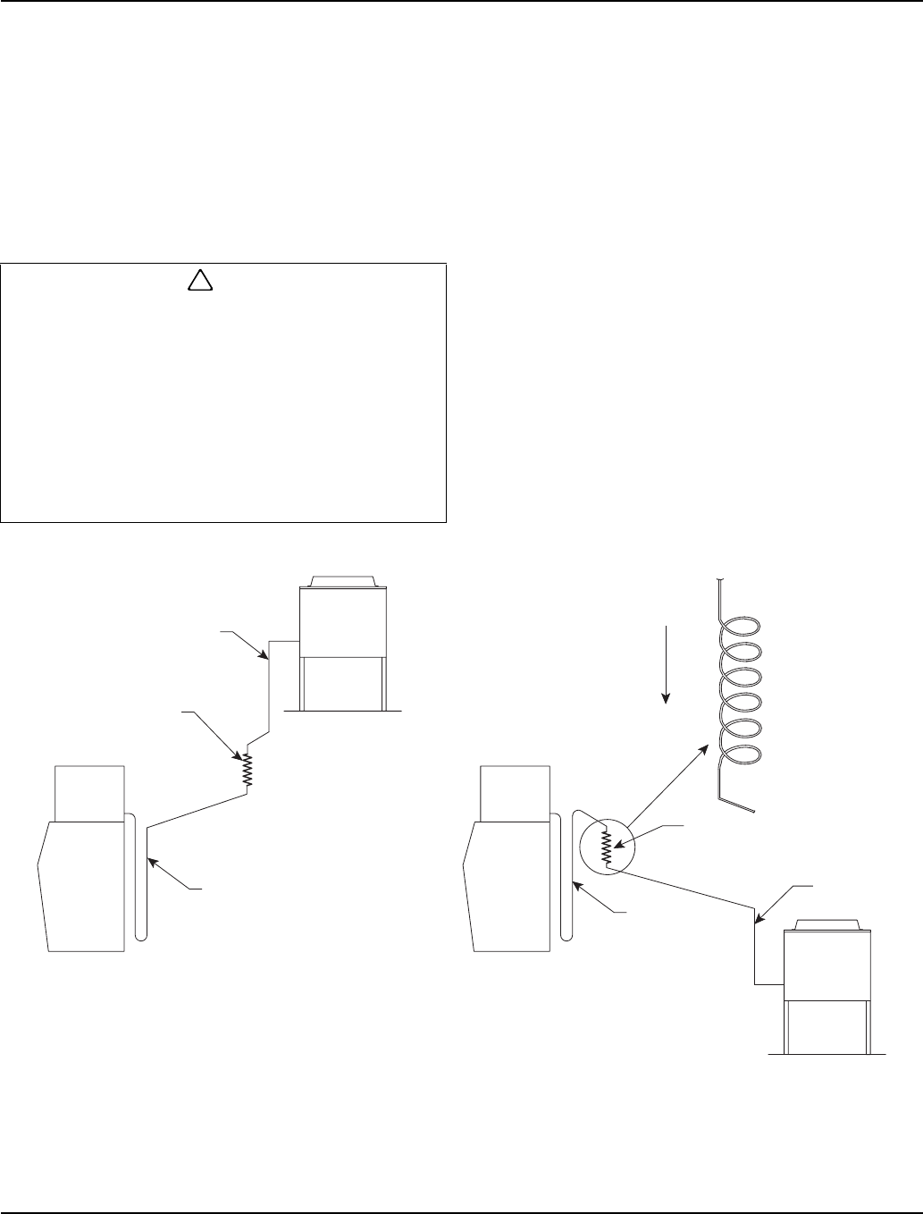
GUIDELINES FOR ROUTING LINE SETS
First, cut a 2.5" (6.35 cm) circular hole in the wall or roof
for tubing routing. The line set end with the 90° bend will
connect to the ice machine. The straight end will connect
to the remote condenser.
Follow these guidelines when routing the refrigerant
lines. This will help insure proper performance and
service accessibility.
1. Optional - Make the service loop in the line sets (as
shown below). This permits easy access to the ice
machine for cleaning and service. Do not use hard
rigid copper at this location.
2. Required - Do not form traps in the refrigeration lines
(except the service loop). Refrigerant oil must be
free to drain toward the ice machine or the
condenser. Route excess tubing in a supported
downward horizontal spiral (as shown below). Do
not coil tubing vertically.
3. Required - Keep outdoor refrigerant line runs as
short as possible.
Routing Line Sets
!
Caution
The 60 month compressor warranty (including the
36 month labor replacement warranty) will not apply
if the remote ice machine is not installed according
to specifications.
This warranty also will not apply if the refrigeration
system is modified with a condenser, heat reclaim
device, or other parts or assemblies not
manufactured by Manitowoc Ice, Inc., unless
specifically approved in writing by Manitowoc Ice,
Inc.
1
2
3
1
2
3
DOWNWARD
HORIZONTAL
SPIRAL
SV1204
Installation Instructions Section 2
2-16 Part Number 80-1480-3
CALCULATING REMOTE CONDENSER
INSTALLATION DISTANCES
Line Set Length
The maximum length is 100' (30.5 m).
The ice machine compressor must have the proper oil
return. The receiver is designed to hold a charge
sufficient to operate the ice machine in ambient
temperatures between -20°F (-29°C) and 120°F (49°C),
with line set lengths of up to 100' (30.5 m).
Line Set Rise/Drop
The maximum rise is 35' (10.7 m).
The maximum drop is 15' (4.5 m).
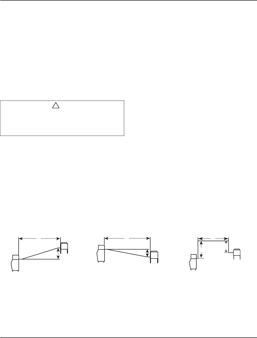
Calculated Line Set Distance
The maximum calculated distance is 150' (45.7 m).
Line set rises, drops, horizontal runs (or combinations of
these) in excess of the stated maximums will exceed
compressor start-up and design limits. This will cause
poor oil return to the compressor.
Make the following calculations to make sure the line set
layout is within specifications.
1. Insert the measured rise into the formula below.
Multiply by 1.7 to get the calculated rise.
(Example: A condenser located 10 feet above the
ice machine has a calculated rise of 17 feet.)
2. Insert the measured drop into the formula below.
Multiply by 6.6 to get the calculated drop.
(Example. A condenser located 10 feet below the
ice machine has a calculated drop of 66 feet.)
3. Insert the measured horizontal distance into the
formula below. No calculation is necessary.
4. Add together the calculated rise, calculated drop,
and horizontal distance to get the total calculated
distance. If this total exceeds 150' (45.7 m), move
the condenser to a new location and perform the
calculations again.
Maximum Line Set Distance Formula
!
Caution
If a line set has a rise followed by a drop, another
rise cannot be made. Likewise, if a line set has a
drop followed by a rise, another drop cannot be
made.
Step 1. Measured Rise (35' [10.7 m] Maximum) ______ x 1.7 =_______ Calculated Rise
Step 2. Measured Drop (15' [4.5 m] Maximum) ______ x 6.6 =_______ Calculated Drop
Step 3. Measured Horizontal Distance (100' [30.5 m] Maximum) _______ Horizontal Distance
Step 4. Total Calculated Distance 150' (45.7 m) _______ Total Calculated Distance
H
R
H
D
H
D
R
Combination of a Rise and a
Horizontal Run Combination of a Drop and a
Horizontal Run Combination of a Rise, a Drop
and a Horizontal Run
SV1196 SV1195 SV1194
Section 2 Installation Instructions
Part Number 80-1480-3 2-17
LENGTHENING OR REDUCING LINE SET LENGTHS
In most cases, by routing the line set properly,
shortening will not be necessary. When shortening or
lengthening is required, do so before connecting the line
set to the ice machine or the remote condenser. This
prevents the loss of refrigerant in the ice machine or
condenser.
The quick connect fittings on the line sets are equipped
with Schraeder valves. Use these valves to recover any
vapor charge from the line set. When lengthening or
shortening lines follow good refrigeration practices,
purge with nitrogen and insulate all tubing. Do not
change the tube sizes. Evacuate the lines and place
about 5 oz (143g) of vapor refrigerant charge in each
line.
CONNECTING A LINE SET
1. Remove the dust caps from the line set, condenser
and ice machine.
2. Apply refrigeration oil to the threads on the quick
disconnect couplers before connecting them to the
condenser.
3. Carefully thread the female fitting to the condenser
or ice machine by hand.
4. Tighten the couplings with a wrench until they
bottom out.
5. Turn an additional 1/4 turn to ensure proper brass-
to-brass seating. Torque to the following
specifications:
6. Check all fittings and valve caps for leaks.
7. Make sure Schraeder cores are seated and
Schraeder caps are on and tight.
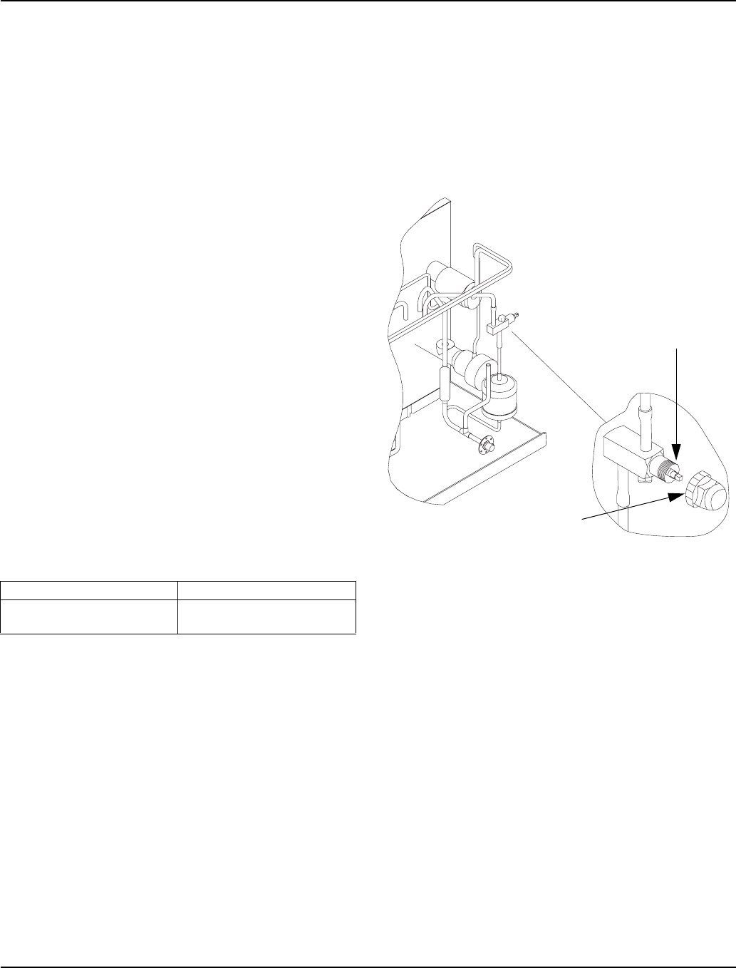
REMOTE RECEIVER SERVICE VALVE
The receiver service valve is closed during shipment.
Open the valve prior to starting the ice machine.
1. Remove the top and left side panels.
2. Remove the receiver service valve cap.
3. Backseat (open) the valve.
4. Reinstall the cap and panels.
Backseating the Receiver Service Valve
Liquid Line Discharge Line
10-12 ft lb.
(13.5-16.2 N•m) 35-45 ft lb.
(47.5-61.0 N•m)
SV1603
REMOVE FRONT, TOP,
AND LEFT SIDE PANEL
FOR ACCESS TO
RECEIVER VALVE
TURN
COUNTERCLOCKWISE
TO OPEN
RECEIVER SERVICE
VALVE CAP (TURN
COUNTERCLOCKWISE
TO REMOVE)
Installation Instructions Section 2
2-18 Part Number 80-1480-3
Remote Ice Machine Usage with Non-Manitowoc Multi-Circuit Condensers
WARRANTY
The sixty (60) month compressor warranty, including
thirty six (36) month labor replacement warranty, shall
not apply when the remote ice machine is not installed
within the remote specifications. The foregoing warranty
shall not apply to any ice machine installed and/or
maintained inconsistent with the technical instructions
provided by Manitowoc Ice, Inc. Performance may vary
from Sales specifications. S-Model ARI certified
standard ratings only apply when used with a Manitowoc
remote condenser.
If the design of the condenser meets the specifications,
Manitowoc’s only approval is for full warranty coverage
to be extended to the Manitowoc manufactured part of
the system. Since Manitowoc does not test the
condenser in conjunction with the ice machine,
Manitowoc will not endorse, recommend, or approve the
condenser, and will not be responsible for its
performance or reliability.
HEAD PRESSURE CONTROL VALVE
Any remote condenser connected to a Manitowoc S-
Model Ice Machine must have a head pressure control
valve #836809-3 (available from Manitowoc Distributors)
installed on the condenser package. Manitowoc will not
accept substitute “off the shelf” head pressure control
valves.
FAN MOTOR
The condenser fan must be on during the complete ice
machine freeze cycle (do not cycle on fan cycle control).
The ice maker has a condenser fan motor circuit for use
with a Manitowoc condenser. It is recommended that this
circuit be used to control the condenser fan(s) on the
multi-circuit condenser to assure it is on at the proper
time. Do not exceed the rated amps for the fan motor
circuit listed on the ice machine’s serial tag.
INTERNAL CONDENSER VOLUME
The multi-circuit condenser internal volume must not be
less than or exceed that used by Manitowoc (see chart
on next page). Do not exceed internal volume and try
to add charge to compensate, as compressor failure
will result.
CONDENSER ∆T
∆T is the difference in temperature between the
condensing refrigerant and entering air. The ∆T should
be 15 to 20°F (-9.4 to -6.6°C) at the beginning of the
freeze cycle (peak load conditions) and drop down to 12
to 17°F (-11.1 to -8.3°C) during the last 75% of the
freeze cycle (average load conditions).
REFRIGERANT CHARGE
Remote ice machines have the serial plate refrigerant
charge (total system charge) located in the ice maker
section. (Remote condensers and line sets are supplied
with only a vapor charge.)
QUICK CONNECT FITTINGS
The ice machine and line sets come with quick connect
fittings. It is recommended that matching quick connects
(available through Manitowoc Distributors) be installed in
the multi-circuit condenser, and that a vapor “holding”
charge (5 oz.) of proper refrigerant be added to the
condenser prior to connection of the ice machine or line
set to the condenser.
Important
Manitowoc warrants only complete new and unused
remote packages. Guaranteeing the integrity of a
new ice machine under the terms of our warranty
prohibits the use of pre-existing (used) tubing or
condensers.
!
Caution
Do not use a fan cycling control to try to maintain
discharge pressure. Compressor failure will result.
!
Caution
Never add more than nameplate charge to ice
machine for any application.
Section 2 Installation Instructions
Part Number 80-1480-3 2-19
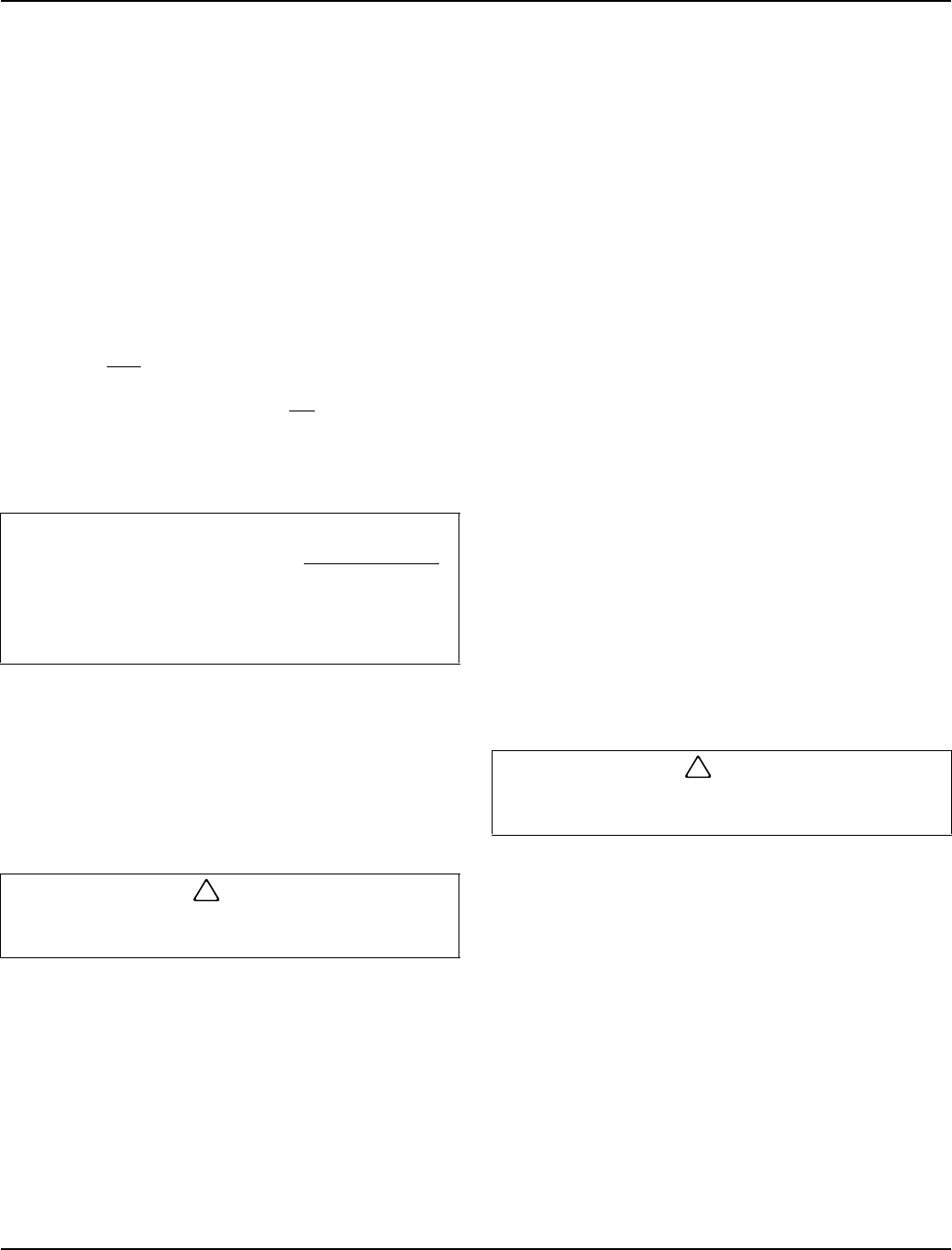
NON-MANITOWOC MULTI-CIRCUIT CONDENSER SIZING CHART
Typical Single Circuit Remote Condenser Installation
Ice
Machine
Model
Refrigerant Heat of Rejection Internal
Condenser
Volume (cu ft) Design
Pressure
Quick Connect Stubs-
Male Ends Head
Pressure
Control
Valve
Type Charge Average
Btu/hr Peak
Btu/hr Min Max Discharge Liquid
S500 R-404A 6 lbs. 7,000 9,600 0.020 0.035
500 psig
(3447 kpa)
(34.47 bar)
safe working
pressure
coupling
P/N
83-6035-3
coupling
P/N
83-6034-3
Manitowoc
P/N
83-6809-3
S600 R404A 6.5 lbs. 9,000 13,900 0.045 0.060
S850 R-404A 8.5 lbs. 12,000 18,000 0.045 0.060 2,500 psig
(17237 kpa)
S1000 R-404A 8.5 lbs. 16,000 22,000 0.045 0.060 (172.37 bar)
burst
pressure no
substitutes
S1400 R-404A 11 lbs. 19,000 28,000 0.085 0.105 mounting
flange P/N
83-6006-3
mounting
flange P/N
83-6005-3
S1800 R-404A 12.5 lbs. 24,000 36,000 0.085 0.105
SV1615
SINGLE CIRCUIT REMOTE
CONDENSER
ELECTRICAL
DISCONNECT
DISCHARGE
LINE
LIQUID LINE
ELECTRICAL
DISCONNECT
ELECTRICAL
SUPPLY
ICE MACHINE
BIN
DISCHARGE
REFRIGERANT
LINE
LIQUID
REFRIGERANT
LINE
36.00"
(91.44 cm)
DROP
TO CIRCUIT
BREAKER
PANEL

Installation Instructions Section 2
2-20 Part Number 80-1480-3
Installation Check List
FIs the Ice Machine level?
FHas all of the internal packing been
removed?
FHave all of the electrical and water
connections been made?
FHas the supply voltage been tested and
checked against the rating on the nameplate?
FIs there proper clearance around the ice
machine for air circulation?
FHas the ice machine been installed where
ambient temperatures will remain in the
range of 35° - 110°F (1.6° - 43.3°C)?
FHas the ice machine been installed where the
incoming water temperature will remain in the
range of 35° - 90°F (1.6° - 32.2°C)?
FIs there a separate drain for the water-cooled
condenser?
FIs there a separate drain for the bin?
FAre the ice machine and bin drains vented?
FAre all electrical leads free from contact with
refrigeration lines and moving equipment?
FHas the owner/operator been instructed
regarding maintenance and the use of
Manitowoc Cleaner and Sanitizer?
FHas the owner/operator completed the
warranty registration card?
FHas the ice machine and bin been sanitized?
FIs the toggle switch set to ice? (The toggle
switch is located directly behind the front
panel).
FIs the ice thickness control set correctly?
(Refer to Operational Checks to check/set
the correct ice bridge thickness).
Additional Checks for Remote Models
FHas the receiver service valve been
opened?
FDoes the remote condenser fan operate
properly after start-up?
FHas the remote condenser been located
where ambient temperatures will remain in
the range of -20° - 120°F ( -29 - 49°C).
FIs the line set routed properly?
FAre both refrigeration lines to remote
condenser run so they do not lay in water
and are properly insulated?

Section 2 Installation Instructions
Part Number 80-1480-3 2-21
Before Starting the Ice Machine
All Manitowoc ice machines are factory-operated and
adjusted before shipment. Normally, new installations do
not require any adjustment.
To ensure proper operation, follow the Operational
Checks in Section 3 of this manual. Starting the ice
machine and completing the Operational Checks are the
responsibilities of the owner/operator.
Adjustments and maintenance procedures outlined in
this manual are not covered by the warranty.
AuCS® Automatic Cleaning System
This optional accessory monitors ice making cycles and
initiates cleaning procedures automatically. The AuCS®
accessory can be set to automatically clean or sanitize
the ice machine every 2, 4 or 12 weeks. Refer to the
AuCS® Installation, Use and Care Manual for details.
!
Warning
Potential Personal Injury Situation
Do not operate equipment that has been misused.
abused, neglected, damaged, or altered/modified
from that of original manufactured specifications.

Installation Instructions Section 2
2-22 Part Number 80-1480-3
THIS PAGE INTENTIONALLY LEFT BLANK
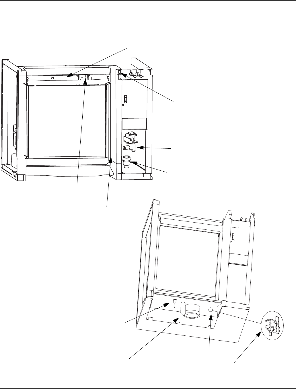
Section 3 Ice Machine Operation
Part Number 80-1480-3 3-1
Section 3
Ice Machine Operation
Component Identification
sv3150
sv3149
Check Valve
Ice Thickness Probe
Dump Valve
Toggle Switch
Water Curtain
Water Distribution Tube
Water Level Probe
Water Pump
Water Inlet Location
Water Inlet Valve
(Located in Refrigeration Compartment)
Bin Switch

Ice Machine Operation Section 3
3-2 Part Number 80-1480-3
Sequence Of Operation
NOTE: The toggle switch must be in the ice position and
the water curtain must be in place on the evaporator
before the ice machine will start.
INITIAL START-UP OR START-UP AFTER
AUTOMATIC SHUT-OFF
1. Water Purge
Before the compressor starts, the water pump and water
dump solenoid are energized for 45 seconds, to
completely purge the ice machine of old water. This
feature ensures that the ice making cycle starts with
fresh water.
The harvest valve(s) is also energized during water
purge, although it stays on for an additional 5 seconds
(50 seconds total on time) during the initial refrigeration
system start-up.
When Used - The air compressor energizes for the last
10 seconds of the cycle.
2. Refrigeration System Start-Up
The compressor starts after the 45 second water purge,
and it remains on throughout the entire Freeze and
Harvest Sequences. The water fill valve is energized at
the same time as the compressor. The harvest valve(s)
remains on for 5 seconds during initial compressor start-
up and then shuts off.
At the same time the compressor starts, the condenser
fan motor (air-cooled models) is supplied with power
throughout the entire Freeze and Harvest Sequences.
The fan motor is wired through a fan cycle pressure
control, therefore it may cycle on and off. (The
compressor and condenser fan motor are wired through
the contactor. As a result, anytime the contactor coil is
energized, the compressor and fan motor are supplied
with power.)
FREEZE SEQUENCE
3. Prechill
The compressor is on for 30 seconds (60 seconds initial
cycle) prior to water flow, to prechill the evaporator. The
water fill valve remains on until the water level probe is
satisfied.
4. Freeze
The water pump restarts after the prechill. An even flow
of water is directed across the evaporator and into each
cube cell, where it freezes. The water fill valve will cycle
on and then off one more time to refill the water trough.
When sufficient ice has formed, the water flow (not the
ice) contacts the ice thickness probe. After
approximately 10 seconds of continual water contact,
the harvest sequence is initiated. The ice machine
cannot initiate a harvest sequence until a 6 minute
freeze lock has been surpassed.
NOTE: Freeze lock is bypassed after moving the toggle
switch from OFF to ICE position for the first cycle only.

Section 3 Ice Machine Operation
Part Number 80-1480-3 3-3
HARVEST SEQUENCE
5. Water Purge
The harvest valve(s) opens at the beginning of the water
purge to divert hot refrigerant gas into the evaporator.
The water pump continues to run, and the water dump
valve energizes for 45 seconds to purge the water in the
sump trough. The water fill valve energizes (turns on)
and de-energizes (turns off) strictly by time. The water fill
valve energizes for the last 15 seconds of the 45-second
water purge.
After the 45 second water purge, the water fill valve,
water pump and dump valve de-energize. (Refer to
“Water Purge Adjustment” for details.)
6. Harvest
The harvest valve(s) remains open and the refrigerant
gas warms the evaporator causing the cubes to slide, as
a sheet, off the evaporator and into the storage bin. The
sliding sheet of cubes swings the water curtain out,
opening the bin switch.
The momentary opening and re-closing of the bin switch
terminates the harvest sequence and returns the ice
machine to the freeze sequence (Step 3 - 4.)
When Used - The air compressor energizes after 35
seconds and remains energized throughout the entire
harvest cycle. The air compressor will automatically
energize for 60 seconds when the harvest cycle time
exceeded 75 seconds in the previous cycle.
AUTOMATIC SHUT-OFF
7. Automatic Shut-Off
When the storage bin is full at the end of a harvest
sequence, the sheet of cubes fails to clear the water
curtain and will hold it open. After the water curtain is
held open for 30 seconds, the ice machine shuts off. The
ice machine remains off for 3 minutes before it can
automatically restart.
The ice machine remains off until enough ice has been
removed from the storage bin to allow the ice to fall clear
of the water curtain. As the water curtain swings back to
the operating position, the bin switch re-closes and the
ice machine restarts (steps 1 - 2), provided the 3 minute
delay period is complete.
SAFETY TIMERS
The control board has the following non-adjustable
safety timers:
• The ice machine is locked into the freeze cycle for 6
minutes before a harvest cycle can be initiated.
Freeze lock is bypassed after moving the toggle
switch from OFF to ICE position for the first cycle
only.
• The maximum freeze time is 60 minutes at which
time the control board automatically initiates a
harvest sequence (steps 5 & 6).
• The maximum harvest time is 3.5 minutes at which
time the control board automatically initiates a freeze
sequence (steps 3 & 4).
WARM WATER RINSE CYCLE
Closing the back of the evaporator allows ice to build up
on the rear of the evaporator and the plastic evaporator
frame parts. After 200 freeze/harvest cycles have been
complete the control board will initiate a warm water
rinse.
After the 200th harvest cycle ends:
• The Clean and Harvest LED’s energize to indicate
the ice machine is in a warm water rinse.
• The compressor and harvest valve remain
energized.
• The water pump energizes.
• The water inlet valve energizes until water contacts
the water level probe.
• The compressor and harvest valve warm the water
for 5 minutes, then de-energize.
• The water pump remains energized for an additional
5 minutes (10 minute total on time) then de-
energizes.
NOTE: The warm water rinse cycle can be terminated by
moving the toggle switch to the OFF position, then back to ICE.
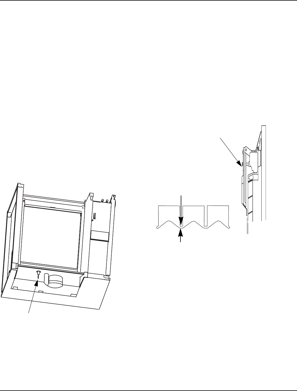
Ice Machine Operation Section 3
3-4 Part Number 80-1480-3
Operational Checks
GENERAL
Manitowoc ice machines are factory-operated and
adjusted before shipment. Normally, new installations do
not require any adjustment.
To ensure proper operation, always follow the
Operational Checks:
• when starting the ice machine for the first time
• after a prolonged out of service period
• after cleaning and sanitizing
NOTE: Routine adjustments and maintenance
procedures are not covered by the warranty.
WATER LEVEL
The water level sensor is set to maintain the proper
water level above the water pump housing. The water
level is not adjustable. If the water level is incorrect,
check the water level probe for damage (probe bent,
etc.). Clean the water level probe with ice machine
cleaner, rinse thoroughly and re-check operation. Repair
or replace the probe as necessary.
ICE THICKNESS CHECK
The ice thickness probe is factory-set to maintain the ice
bridge thickness at 1/8" (.32 cm).
NOTE: Make sure the water curtain is in place when
performing this check. It prevents water from splashing
out of the water trough.
1. Inspect the bridge connecting the cubes. It should
be about 1/8" (.32 cm) thick.
2. If adjustment is necessary, turn the ice thickness
probe adjustment screw clockwise to increase
bridge thickness, counterclockwise to decrease
bridge thickness. Set at 1/4” gap between ice
machine and evaporator as starting point, then
adjust to achieve a 1/8” bridge thickness.
Ice Thickness Check
3. Make sure the ice thickness probe wire and the
bracket do not restrict movement of the probe.
Water Level Probe Location
SV3132
ADJUSTING SCREW
1/8” ICE BRIDGE THICKNESS
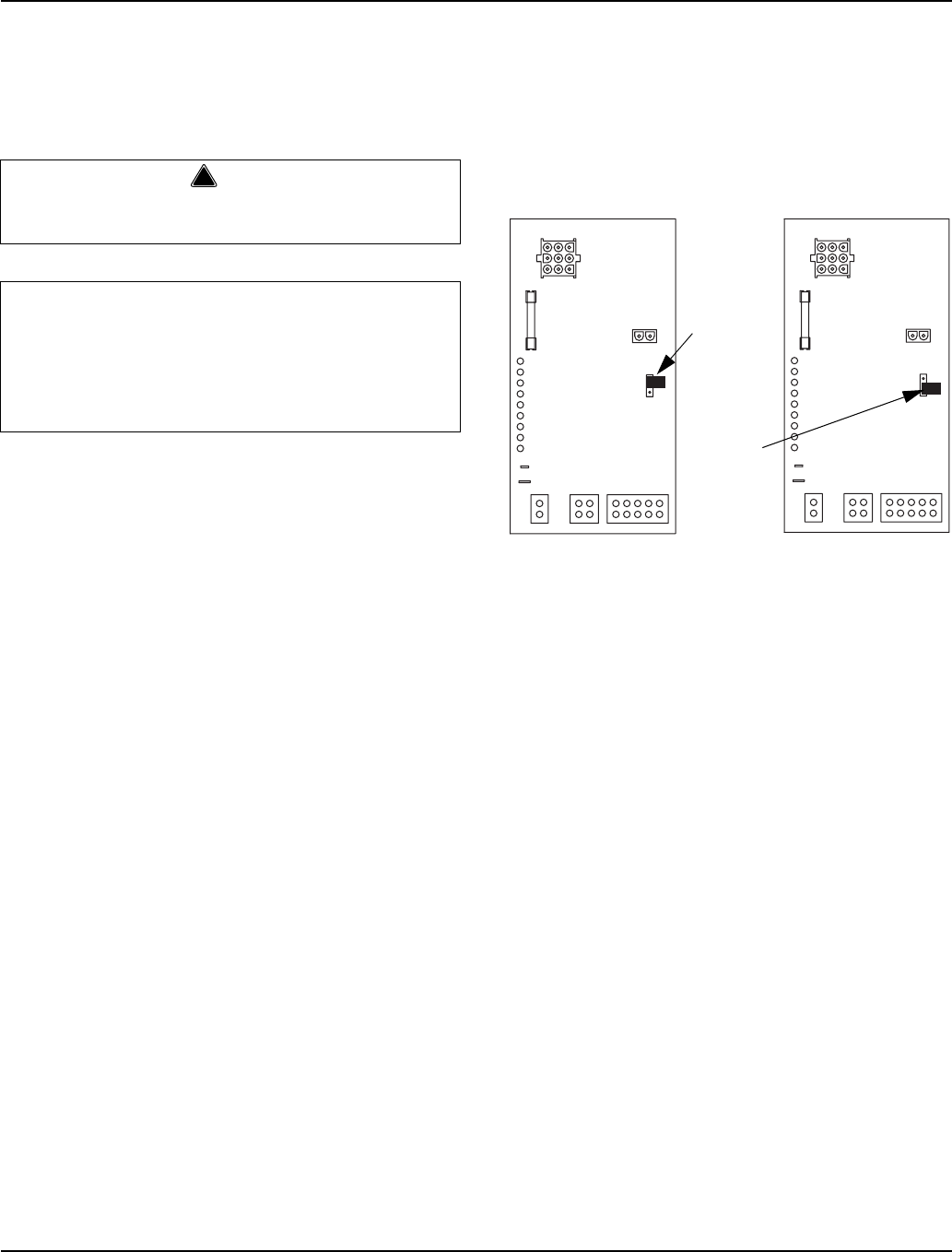
Section 3 Ice Machine Operation
Part Number 80-1480-3 3-5
HARVEST SEQUENCE WATER PURGE
The harvest sequence water purge adjustment may be
used when the ice machine is hooked up to special
water systems, such as a de-ionized water treatment
system.
• The harvest sequence water purge is factory set for
45 seconds. Repositioning the jumper will set the
harvest water purge to 0 seconds. This setting does
not affect the SeCs or AuCs (cleaning) sequences.
• During the harvest sequence water purge, the water
fill valve energizes and de-energizes by time. The
water purge must be at the factory setting of 45
seconds for the water fill valve to energize during the
last 15 seconds of the water purge. If it is set to less
than 45 seconds, the water fill valve will not energize
during the water purge.
Water Purge Adjustment
For your safety and to eliminate errors, we recommend
that a qualified service technician make the harvest
water purge adjustment.
!
Warning
Disconnect electric power to the ice machine at the
electrical disconnect before proceeding.
Important
The harvest sequence water purge is factory-set at
45 seconds. A shorter purge setting (with standard
water supplies such as city water) is not
recommended. This can increase water system
cleaning and sanitizing requirements.
SV3139
SV3140
45 second
setting
0 second
setting

Ice Machine Operation Section 3
3-6 Part Number 80-1480-3
THIS PAGE INTENTIONALLY LEFT BLANK
Section 4 Maintenance
Part Number 80-1480-3 4-1
Section 4
Maintenance
General
You are responsible for maintaining the ice machine in
accordance with the instructions in this manual.
Maintenance procedures are not covered by the
warranty.
We recommend that you perform the following
maintenance procedures a minimum of once every six
months to ensure reliable, trouble-free operation and
maximum ice production.
Ice Machine Inspection
Check all water fittings and lines for leaks. Also, make
sure the refrigeration tubing is not rubbing or vibrating
against other tubing, panels, etc.
Do not put anything (boxes, etc.) on the sides or back of
the ice machine. There must be adequate airflow
through and around the ice machine to maximize ice
production and ensure long component life.
Exterior Cleaning
Clean the area around the ice machine as often as
necessary to maintain cleanliness and efficient
operation. Use cleaners designed for use with stainless
steel products.
Sponge any dust and dirt off the outside of the ice
machine with mild soap and water. Wipe dry with a
clean, soft cloth.
Heavy stains should be removed with stainless steel
wool. Never use plain steel wool or abrasive pads. They
will scratch the panels.
Cleaning the Condenser
GENERAL
A dirty condenser restricts airflow, resulting in
excessively high operating temperatures. This reduces
ice production and shortens component life. Clean the
condenser at least every six months. Follow the steps
below.
1. The washable aluminum filter on self-contained ice
machines is designed to catch dust dirt lint and
grease. Clean the filter with a mild soap and water.
2. Clean the outside of the condenser with a soft brush
or a vacuum with a brush attachment. Be careful not
to bend the condenser fins.
3. Shine a flashlight through the condenser to check
for dirt between the fins. If dirt remains:
A. Blow compressed air through the condenser fins
from the inside. Be careful not to bend the fan
blades.
B. Use a commercial condenser coil cleaner.
Follow the directions and cautions supplied with
the cleaner.
Continued on Next Page...
!Warning
If you do not understand the procedures or the
safety precautions that must be followed, call your
local Manitowoc service representative to perform
the maintenance procedures for you.
!Warning
Disconnect electric power to the ice machine and
the remote condensing unit at the electric service
switch before cleaning the condenser.
!Warning
Disconnect electric power to the ice machine head
section and the remote condensing unit at the
electric service switches before cleaning the
condenser.
!Warning
The condenser fins are sharp. Use care when
cleaning them.
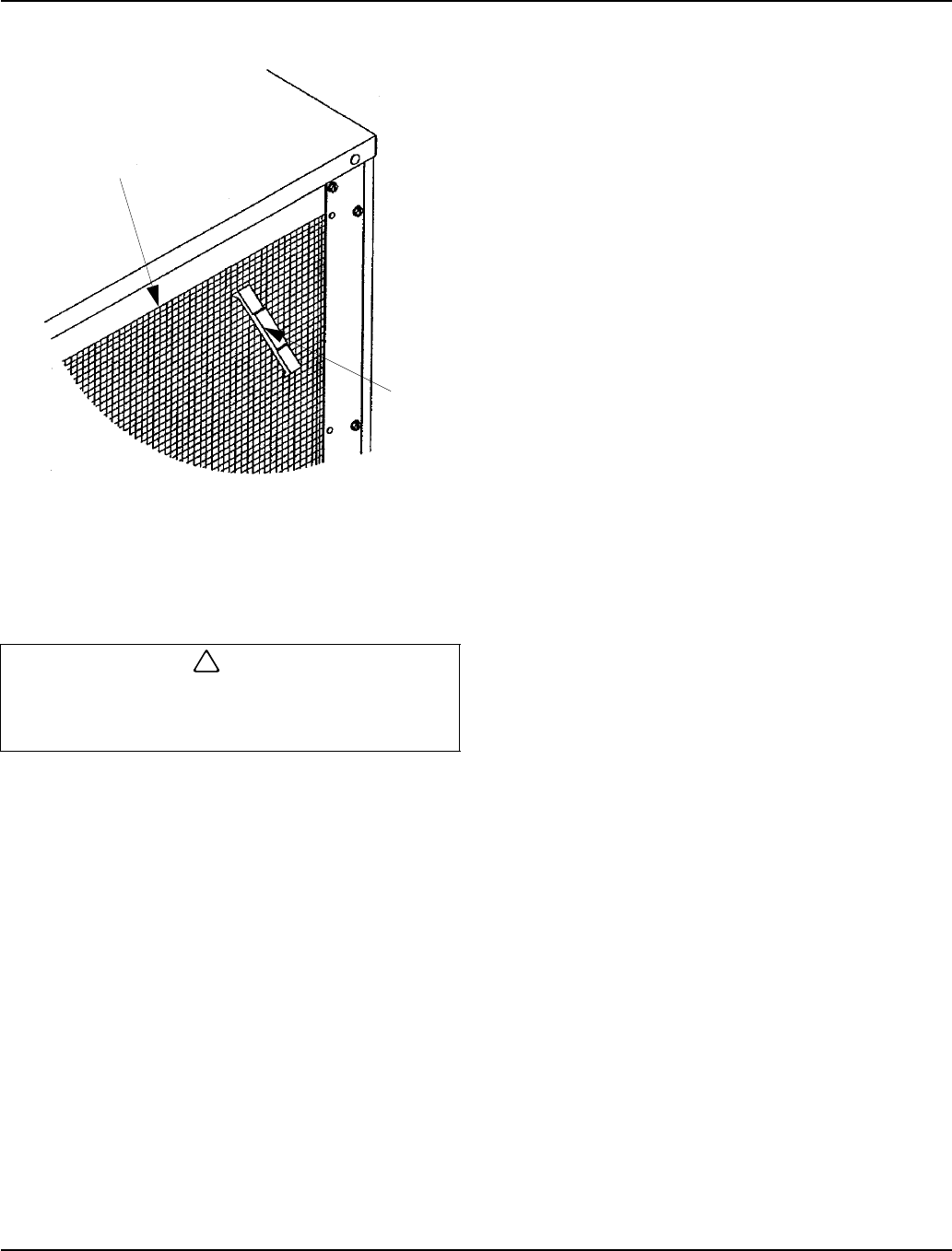
Maintenance Section 4
4-2 Part Number 80-1480-3
4. Straighten any bent condenser fins with a fin comb.
Straighten Bent Condenser Fins
5. Carefully wipe off the fan blades and motor with a
soft cloth. Do not bend the fan blades. If the fan
blades are excessively dirty, wash with warm, soapy
water and rinse thoroughly.
Water-Cooled Condenser
and Water Regulating Valve
Symptoms of restrictions in the condenser water circuit
include:
• Low ice production
• High water consumption
• High operating temperatures
• High operating pressures
If the ice machine is experiencing any of these symptoms,
the water-cooled condenser and water regulating valve
may require cleaning due to scale build-up.
Because the cleaning procedures require special pumps
and cleaning solutions, qualified maintenance or service
personnel must perform them.
AlphaSan
The goal of AlphaSan is to keep the plastic surfaces of
an ice machine cleaner, by reducing or delaying the
formation of bio-film. The active ingredient in
AlphaSan is the element silver in the form of silver ions
(Ag+). AlphaSan slowly releases silver ions via an ion
exchange mechanism. When AlphaSan is
compounded directly into a plastic part, a controlled
release of silver ions from the surface is regulated to
maintain an effective concentration at or near the
surface of the plastic ice machine part. AlphaSan’s
unique ability to effectively control the release of silver
not only protects against undesired discoloration of the
plastic, but also will last the life of the plastic part.
Although AlphaSan helps prevent bio-film build up it
does not eliminate the need for periodic cleaning and
maintenance. AlphaSan has no adverse effect on the
taste of the ice or beverage.
!Caution
If you are cleaning the condenser fan blades with
water, cover the fan motor to prevent water damage
and disconnect electrical power.
SV1515
FIN
COMBS
CONDENSER
“COMB” DOWN
ONLY
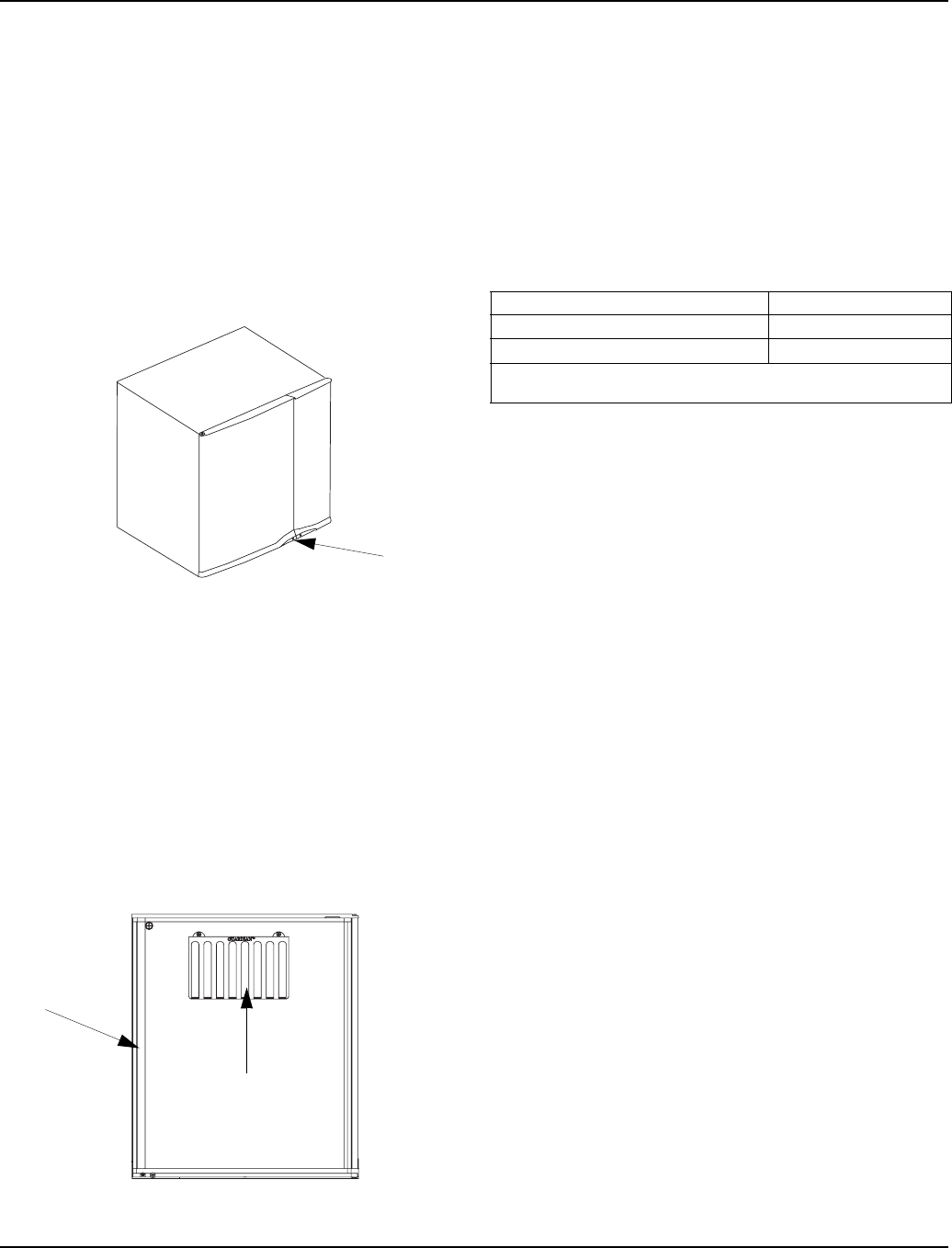
Section 4 Maintenance
Part Number 80-1480-3 4-3
Guardianf
Slime is a leading cause of ice machine breakdowns and biological growth is a health concern. The Guardianf system
releases chlorine dioxide on a controlled basis to inhibit the growth of bacteria and fungi that form slime and cause
malodors in the food zone of ice machines. The Guardianf will not control mineral or other water borne buildup. Your
water quality will determine the length of time before mineral buildup affects ice machine performance. Mineral
buildup must be removed as often as necessary to ensure trouble-free operation of the ice machine.
INSTALLATION
If the Guardian system has been ordered, install the
sachet holder in the inside of the front panel.
1. Loosen the left screw and open the left front door.
The right front panel does not need to be removed.
Screw Location
2. Inside the front panel there are two thumbscrew
holes covered by stickers, pierce the sticker with a
screwdriver.
3. Attach the sachet holder to the front panel by
inserting the thumbsrews through the holes in the
sachet holder and tightening the thumbscrews
4. Remove the new sachet packet from foil package
and install into holder. Removing the foil package
allows moisture in the air to activate the sachet
contents.
5. Close the left front door and tighten the screw.
Guardianf Location
SACHET REPLACEMENT FREQUENCY
Sachet packet(s) require replacement every thirty (30)
days or whenever they come in direct contact with water.
Refer to chart below for requirements.
Guardianf sachet packets are available through your
local Manitowoc ice machine dealer.
SACHET REPLACEMENT PROCEDURE
1. Loosen the left screw and open the left front door.
The right front panel does not need to be removed.
2. Remove and discard spent Guardian sachet
packets.
3. Remove the new sachet packet from foil package
and install into holder. Removing the foil package
allows moisture in the air to activate the sachet
contents.
4. Close the left front door and tighten the screw.
5. Discard the use sachet packet in the trash.
CLEAN UP PROCEDURE FOR DAMAGED PACKET
1. Remove all ice from bin/dispenser and discard.
2. Initiate a cleaning and sanitizing sequence on the
ice machine (see next pages).
3. Clean the bin/dispenser. Flush the drain thoroughly
to prevent future drain blockage.
4. Sanitize the bin/dispenser.
5. Install a replacement sachet packet and reinstall all
panels.
Loosen
Screw
Guardian
Inside Left
Front Door
Ice Machine Sachet Use
S300/S320/S420/S450/S500/S600 1
S850/S1000/S1400/S1800 1 or 2*
*Although one sachet is recommended, extreme conditions may
necessitate using two sachet packets.
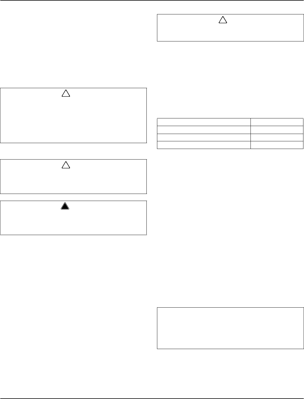
Maintenance Section 4
4-4 Part Number 80-1480-3
Interior Cleaning and Sanitizing
GENERAL
Clean and sanitize the ice machine every six months for
efficient operation. If the ice machine requires more
frequent cleaning and sanitizing, consult a qualified
service company to test the water quality and
recommend appropriate water treatment. An extremely
dirty ice machine must be taken apart for cleaning and
sanitizing.
CLEANING PROCEDURE
Ice machine cleaner is used to remove lime scale or
other mineral deposits. It is not used to remove algae or
slime. Refer to the section on Sanitizing for removal of
algae and slime.
Step 1 Set the toggle switch to the OFF position after
ice falls from the evaporator at the end of a Harvest
cycle. Or, set the switch to the OFF position and allow
the ice to melt off the evaporator.
Step 2 To start cleaning, place the toggle switch in the
CLEAN position. The water will flow through the water
dump valve and down the drain. The Clean light will turn
on to indicate the ice machine is in the Cleaning mode.
Step 3 Wait about two minutes or until water starts to
flow over the evaporator.
Step 4 Add the proper amount of Manitowoc Ice
Machine Cleaner to the water trough.
Step 5 The ice machine will automatically time out a
ten minute cleaning cycle, followed by six rinse cycles,
and stop. The Clean light will turn off to indicate the
Cleaning cycle is completed. This entire cycle lasts
approximately 30 minutes.
Step 6 When the cleaning process stops, move the
toggle switch to OFF position. Refer to “Sanitizing
Procedure” on the next page.
Step 7
A. The ice machine may be set to start and finish a
self-cleaning procedure then automatically start
ice making again.
B. You must wait about one minute into the
cleaning cycle (until water starts to flow over the
evaporator) then move the switch from CLEAN
to ICE position.
C. When the self-cleaning cycle is completed, an
ice making sequence will start automatically.
!Caution
Use only Manitowoc approved Ice Machine Cleaner
(part number 94-0546-3) and Sanitizer (part number
94-0565-3). It is a violation of Federal law to use
these solutions in a manner inconsistent with their
labeling. Read and understand all labels printed on
bottles before use.
!Caution
Do not mix Cleaner and Sanitizer solutions together.
It is a violation of Federal law to use these solutions
in a manner inconsistent with their labeling.
!Warning
Wear rubber gloves and safety goggles (and/or face
shield) when handling ice machine Cleaner or
Sanitizer.
!Caution
Never use anything to force ice from the evaporator.
Damage may result.
Model Amount of Cleaner
S300/S320/S420 3 ounces (88 ml)
S450/S500/S600/S850/S1000/ 5 ounces (148 ml)
S1400/S1800 9 ounces (266 ml)
Important
After the toggle switch is moved to the ICE position,
opening the curtain switch will interrupt the cleaning
sequence. The sequence will resume from the point
of interruption when the curtain switch closes.
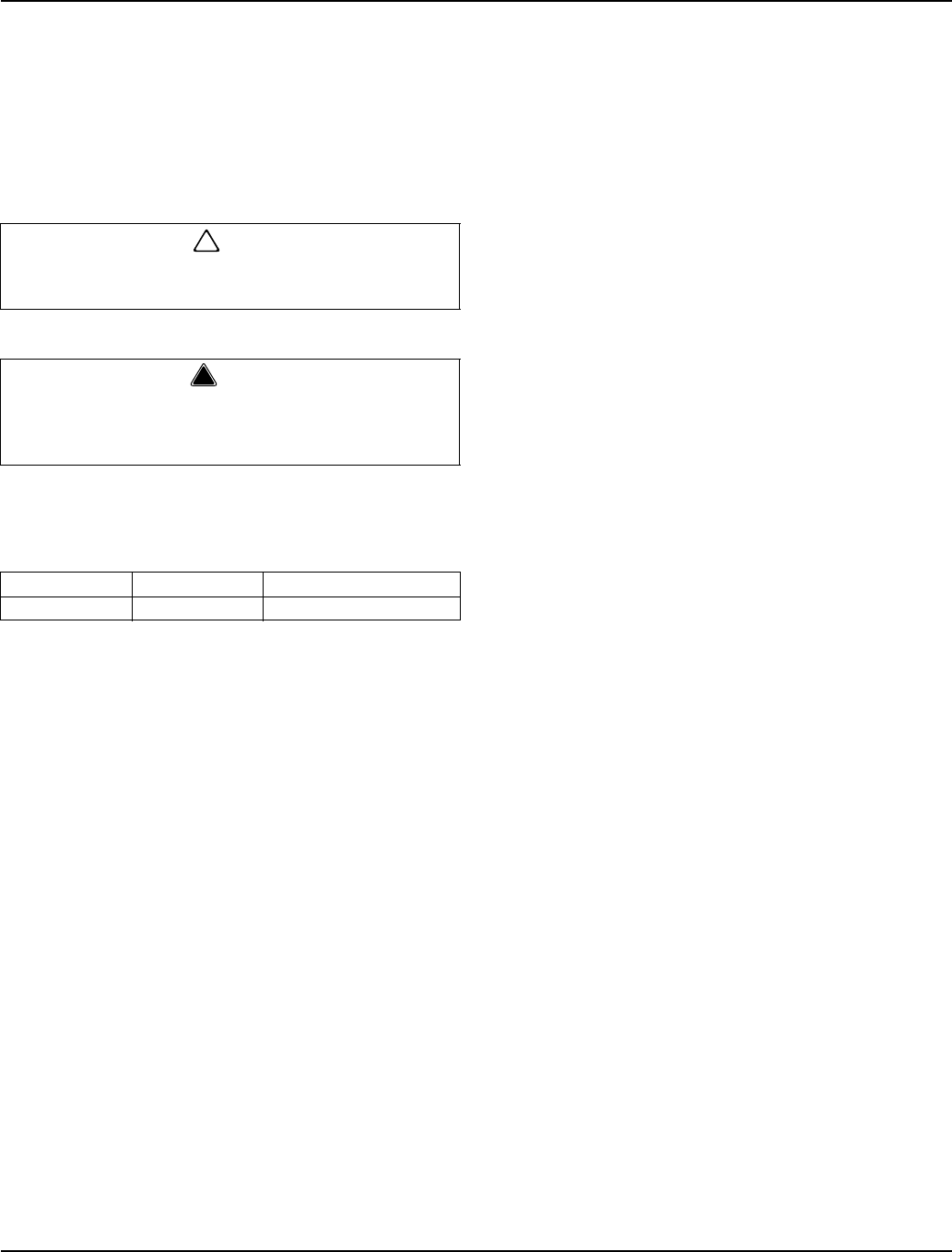
Section 4 Maintenance
Part Number 80-1480-3 4-5
SANITIZING PROCEDURE
Use sanitizer to remove algae or slime. Do not use it to
remove lime scale or other mineral deposits.
Step 1 Set the toggle switch to the OFF position after
ice falls from the evaporator at the end of a Harvest
cycle. Or, set the switch to the OFF position and allow
the ice to melt off the evaporator.
Step 2 Refer to Removal of Parts For Cleaning/
Sanitizing and remove ice machine parts.
Step 3 Mix a solution of water and sanitizer.
Step 4 Use the sanitizing solution and a sponge or
cloth to sanitize (wipe) all parts and interior surfaces of
the ice machine. Sanitize the following areas:
A. Side walls
B. Base (area above water trough)
C. Evaporator plastic parts
D. Bin or dispenser
Step 5 Rinse all sanitized areas with clear water.
Step 6 Install the removed parts, restore power and
place toggle switch in the ice position.
!Caution
Never use anything to force ice from the evaporator.
Damage may result.
!Warning
Disconnect electric power to the ice machine (and
dispenser if applicable) at the electric switch box
before proceeding.
Solution Type Water Mixed With
Sanitizer 4 gal. (15 l) 3 oz (90 ml) sanitizer
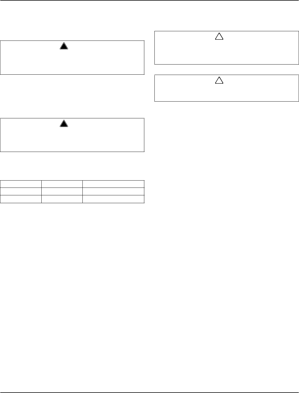
Maintenance Section 4
4-6 Part Number 80-1480-3
REMOVAL OF PARTS FOR CLEANING/SANITIZING
1. Turn off the electrical and water supply to the ice
machine (and dispenser when applicable).
2. Remove all ice from the bin.
3. Remove the water curtain and the components you
want to clean or sanitize. See the following pages for
removal procedures for these parts.
4. Soak the removed part(s) in a properly mixed
solution.
5. Use a soft-bristle brush or sponge (NOT a wire
brush) to carefully clean the parts.
6. Use the sanitizing solution and a sponge or cloth to
sanitize (wipe) the interior of the ice machine and
the entire inside of the bin/dispenser.
7. Thoroughly rinse all of the parts and surfaces with
clear water.
8. Install the removed parts.
NOTE: Incomplete rinsing of the ice thickness probe or
water level probe may leave a residue. This could cause
the ice machine to malfunction. For best results, brush or
wipe the probes off while rinsing it. Thoroughly dry the
probes before installing them.
9. Turn on the water and electrical supply.
!Warning
Disconnect electric power to the ice machine (and
dispenser if applicable) at the electric switch box
before proceeding.
!Warning
Wear rubber gloves and safety goggles (and/or face
shield) when handling Ice Machine Cleaner or
Sanitizer.
Solution Type Water Mixed With
Cleaner 1 gal. (4 l) 16 oz (500 ml) cleaner
Sanitizer 4 gal. (15 l) 3 oz (90 ml) sanitizer
!Caution
Do not mix Cleaner and Sanitizer solutions together.
It is a violation of Federal law to use these solutions
in a manner inconsistent with their labeling.
!Caution
Do not immerse the water pump motor in the
cleaning or sanitizing solution.
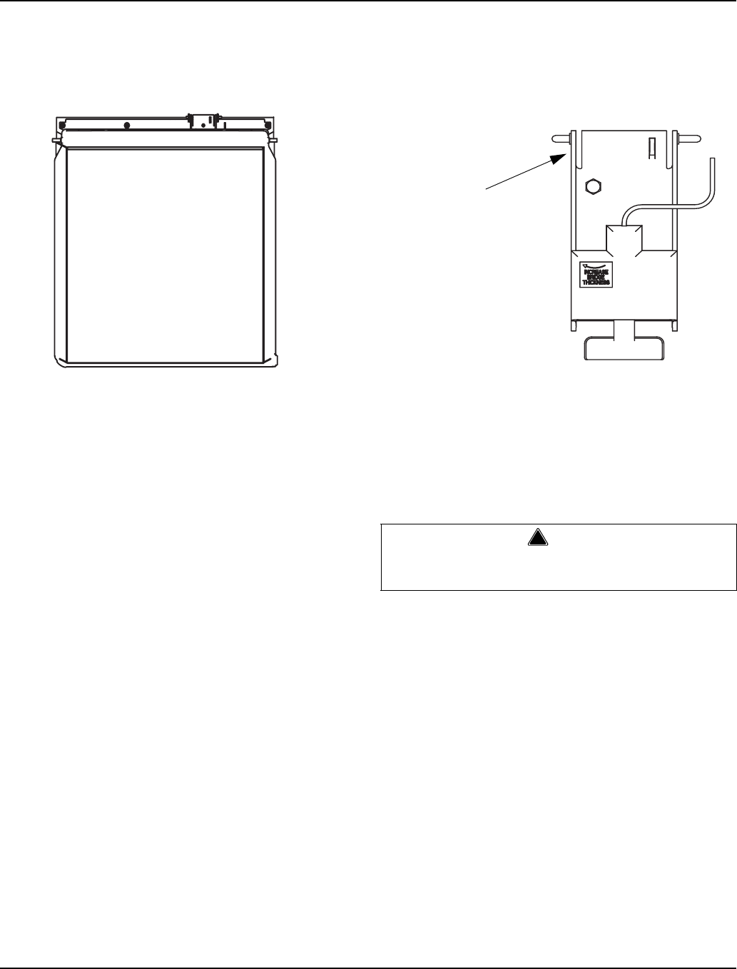
Section 4 Maintenance
Part Number 80-1480-3 4-7
1. Water Curtain
A. Gently flex the curtain in the center and remove
it from the right side.
B. Slide the left pin out.
Water Curtain Removal
2. Ice Thickness Probe
A. Compress the hinge pin on the top of the ice
thickness probe.
Ice Thickness Probe Removal
B. Pivot the ice thickness probe to disengage one
pin then the other. The ice thickness probe can
be cleaned at this point without complete
removal. Follow Step C for complete removal.
C. Disconnect the ice thickness control wiring from
the control board.
SV3153
STEP 1
STEP 2
!Warning
Disconnect the electric power to the ice machine at
the electric service switch box.
SV3135
COMPRESS
HINGE PIN TO
REMOVE
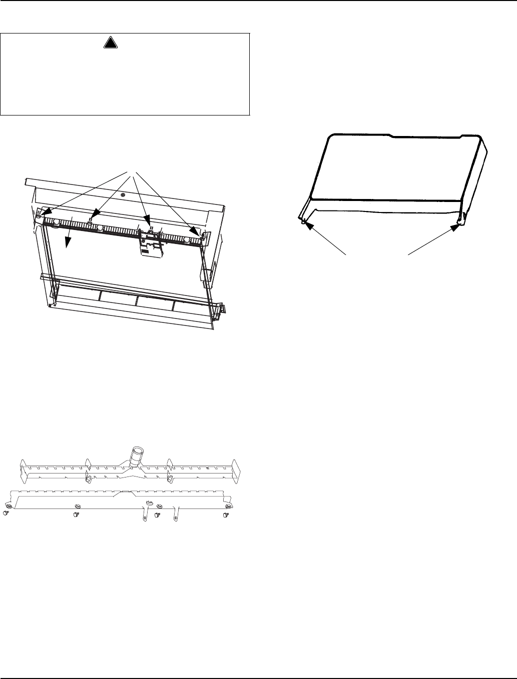
Maintenance Section 4
4-8 Part Number 80-1480-3
3. Water Distribution Tube
NOTE: Distribution tube thumbscrews are retained by o-
rings to prevent loss. Loosen thumbscrews but do not
pull thumbscrews out of distribution tube.
Water Distribution Tube Removal
A. Remove outer half of distribution tube by
loosening the four (4) thumbscrews (o-rings
retain thumbscrews to distribution tube).
B. Pull inner half of water distribution tube forward
to release slip joint from water pump tubing
connection.
4. Water Trough
A. Depress tabs on right and left side of the water
trough.
B. Allow front of water trough to drop as you pull
forward to disengage the rear pins.
!Warning
Removing the distribution tube while the water
pump is running will allow water to spray from ice
machine. Disconnect the electrical power to the ice
machine and dispenser at the electric service switch
box and turn off the water supply.
A
B
DEPRESS TABS
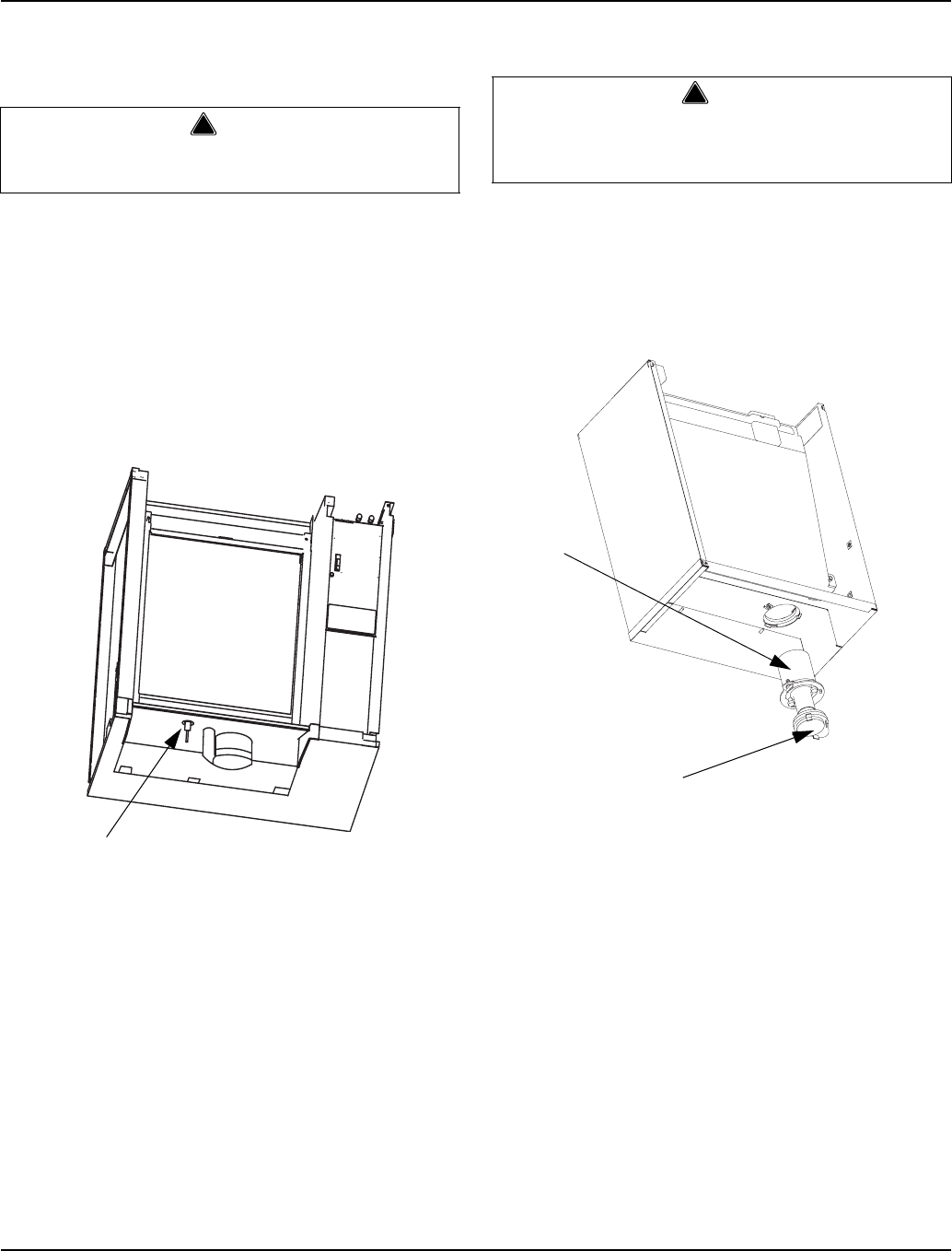
Section 4 Maintenance
Part Number 80-1480-3 4-9
Water Level Probe
1. Remove the water trough.
2. The water level probe normally does not require
removal for cleaning. The probe can be wiped and
cleaned in place or proceed to step 3.
3. Pull the water level probe straight down to
disengage.
4. Lower the water level probe until the wiring
connector is visible. Disconnect the wire lead from
the water level probe.
5. Remove the water level probe from the ice machine.
Water Pump
1. Empty the water trough.
A. Move the toggle switch from OFF to ICE.
B. Wait 45 seconds.
C. Place toggle switch in OFF position.
Water Pump Removal
2. Remove the water trough.
3. The water pump normally does not require removal
for cleaning. The water pump base can be wiped
and cleaned in place or proceed to step 4.
4. Grasp pump and pull straight down on pump
assembly until water pump disengages and
electrical connector is visible.
5. Disconnect the electrical connector.
6. Remove the water pump assembly from ice
machine.
7. Do not soak the water pump in cleaner or sanitizer.
Wipe the pump and ice machine base clean.
!Warning
Disconnect the electrical power to the ice machine
at the electrical disconnect before proceeding.
SV3141
WATER LEVEL PROBE
!Warning
Disconnect the electric power to the ice machine at
the electric service switch box and turn off the water
supply before proceeding.
SV3091
WATER
PUMP
WATER
PUMP BASE
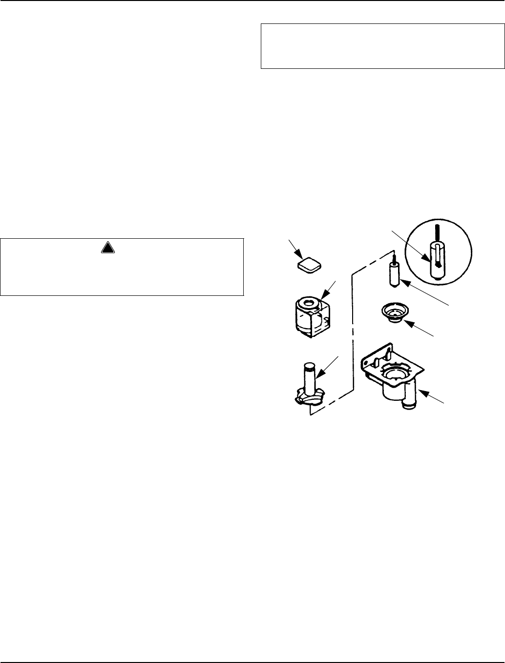
Maintenance Section 4
4-10 Part Number 80-1480-3
Water Dump Valve
The water dump valve normally does not require
removal for cleaning. To determine if removal is
necessary:
1. Locate the water dump valve.
2. Set the toggle switch to ICE.
3. While the ice machine is in the freeze mode, check
the dump valve’s clear plastic outlet drain hose for
leakage.
A. If the dump valve is leaking, remove,
disassemble and clean it.
B. If the dump valve is not leaking, do not remove
it. Instead, follow the “Ice Machine Cleaning
Procedure”.
Follow the procedure below to remove the dump valve.
1. If so equipped, remove the water dump valve shield
from its mounting bracket.
2. Lift and slide the coil retainer cap from the top of the
coil.
3. Note the position of the coil assembly on the valve
for assembly later. Leaving the wires attached, lift
the coil assembly off the valve body and the
enclosing tube.
4. Press down on the plastic nut on the enclosing tube
and rotate it 1/4 turn. Remove the enclosing tube,
plunger, and plastic gasket from the valve body.
NOTE: At this point, the water dump valve can easily be
cleaned. If complete removal is desired, continue with
step 5.
NOTE: During cleaning, do not stretch, damage or
remove the spring from the plunger. If it is removed, slide
the spring’s flared end into the plunger’s slotted top
opening until the spring contacts the plunger spring stop.
5. Remove the valve body.
6. Remove the tubing from the dump valve by twisting
the clamps off.
7. Remove the two screws securing the dump valve
and the mounting bracket.
Dump Valve Disassembly
!Warning
Disconnect the electric power to the ice machine at
the electric service switch box and turn off the water
supply before proceeding.
Important
The plunger and the inside of the enclosing tube
must be completely dry before assembly.
CAP
PLUNGER
SPRING STOP
SPRING
PLUNGER
DIAPHRAM
VALVE BODY
ENCLOSING
TUBE
COIL
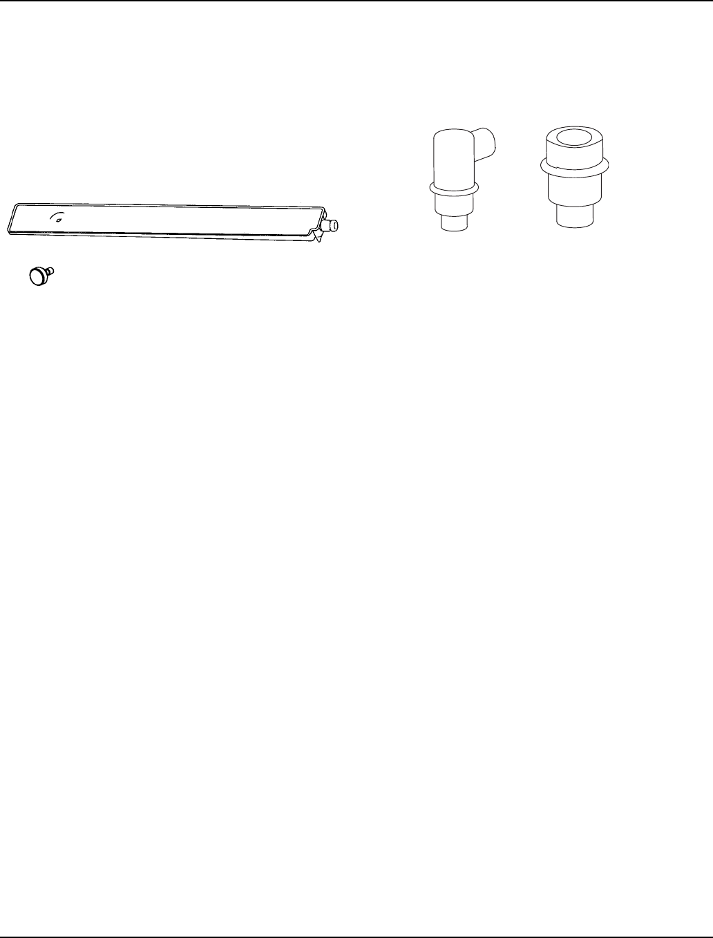
Section 4 Maintenance
Part Number 80-1480-3 4-11
Evaporator Tray Removal
1. Remove the water trough.
2. Remove thumbscrew on left side of tray.
3. Allow left side of tray to drop as you pull the tray to
the left side. Continue until the outlet tube
disengages from the right side.
Drain Line Check Valve
The drain line check valve normally does not require
removal for cleaning. Water loss from the sump trough
will indicate removal and cleaning are required.
1. Remove check valve and tube assembly.
A. Tip assembly to right until tubing disengages.
B. Lift up on assembly to remove.
2. Remove insulation from check valve assembly.
3. Remove vinyl tubing from top of check valve.
4. Soak in cleaner solution 10 minutes, and then flush
with water to remove debris.
sv3154
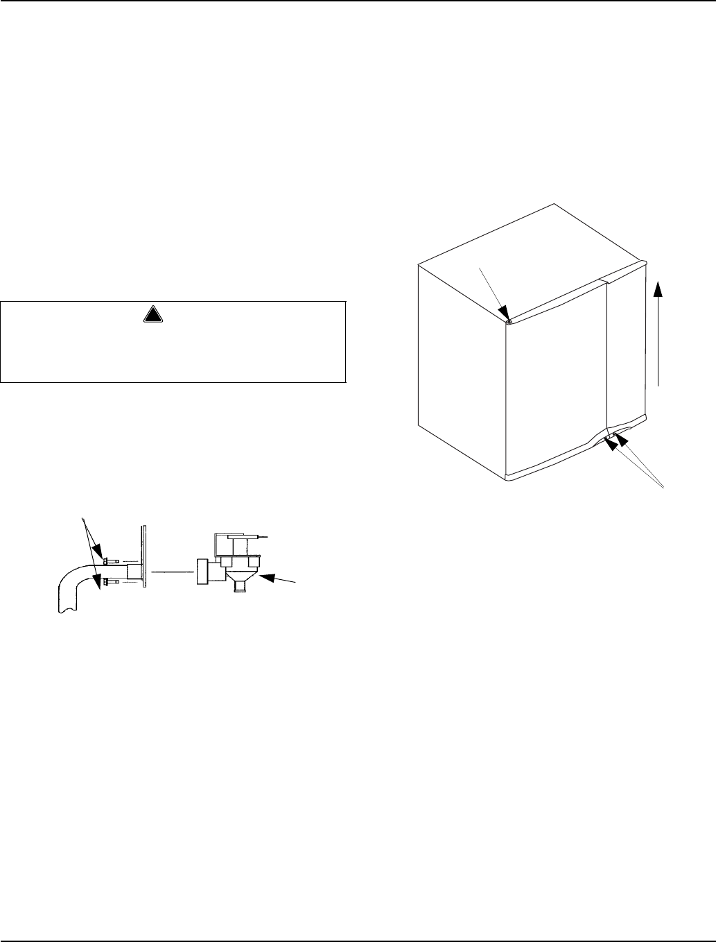
Maintenance Section 4
4-12 Part Number 80-1480-3
Water Inlet Valve
The water inlet valve normally does not require removal
for cleaning. Refer to Section 5 for a list of causes for
“No Water Entering Water Trough” or “Water Overflows
Water Trough.
1. When the ice machine is off, the water inlet valve
must completely stop water flow into the machine.
2. When the ice machine is on, the water inlet valve
must allow the proper water flow through it. Set the
toggle switch to ON. Watch for water flow into the ice
machine. If the water flow is slow or only trickles into
the ice machine, refer to Section 5.
Follow the procedure below to remove the water inlet
valve.
1. Remove the 1/4” hex head screws.
2. Remove, clean, and install the filter screen.
Removing the Front Panels
NOTE: The front panels do not normally have to be
removed. If needed perform the following procedure.
1. Loosen screws. Do not remove they are retained by
o-rings to prevent loss.
2. 30 Inch and 48 Inch Models Only: To remove right
front door lift up and remove (22 inch machines have
a single door, proceed to step 3).
Door Removal
3. Open left front door to 45 degrees.
4. Support with left hand, depress top pin, tilt top of
door forward and lift out of bottom pin to remove.
!Warning
Disconnect the electric power to the ice machine
and dispenser at the electric service switch box and
turn off the water supply before proceeding.
SV1622
FILTER
ACCESS
SCREWS
WATER
INLET
VALVE
3
2
5
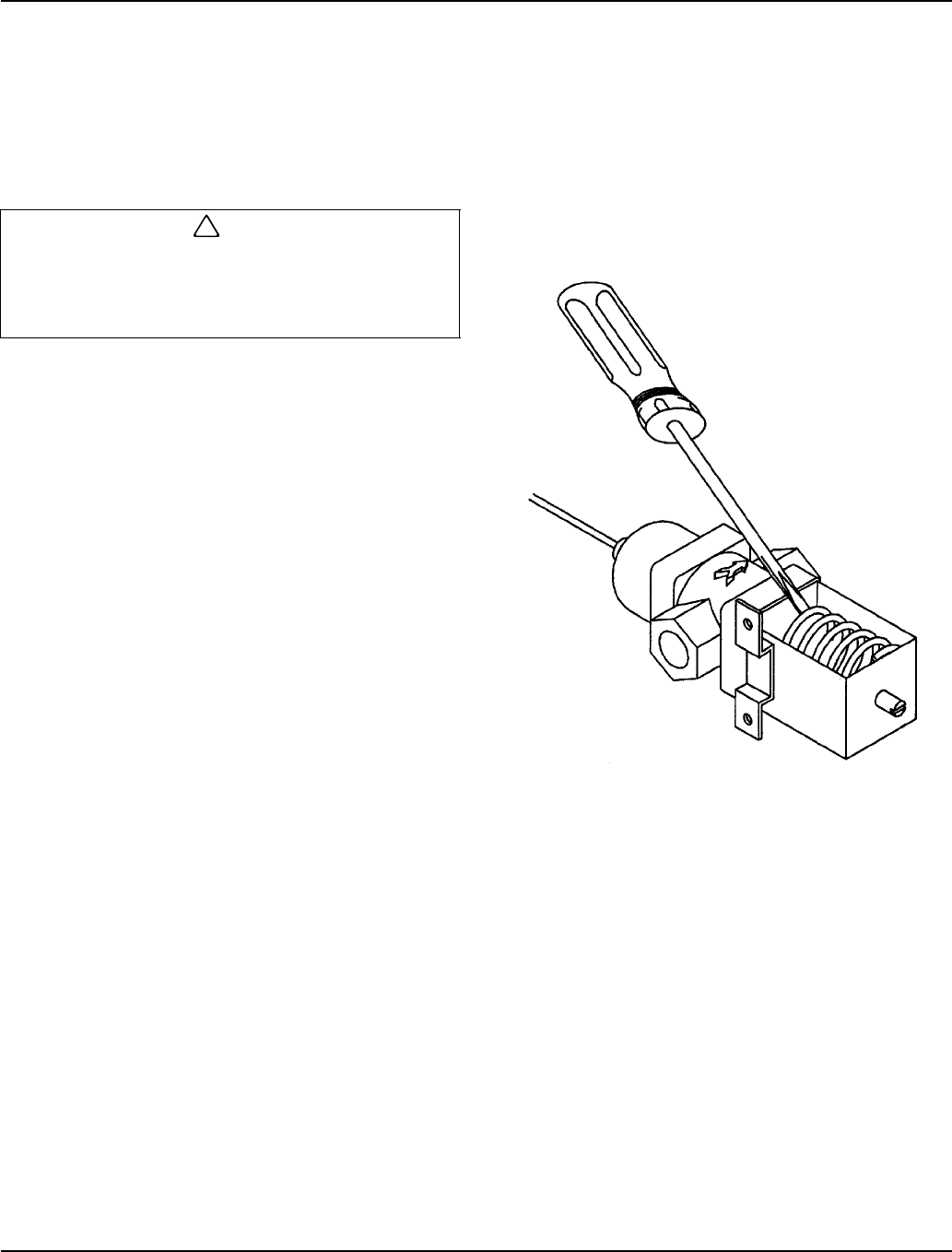
Section 4 Maintenance
Part Number 80-1480-3 4-13
Removal from Service/Winterization
GENERAL
Special precautions must be taken if the ice machine is
to be removed from service for an extended period of
time or exposed to ambient temperatures of 32°F (0°C)
or below.
Follow the applicable procedure below.
SELF-CONTAINED AIR-COOLED ICE MACHINES
1. Disconnect the electric power at the circuit breaker
or the electric service switch.
2. Turn off the water supply.
3. Remove the water from the water trough.
4. Disconnect and drain the incoming ice-making water
line at the rear of the ice machine.
5. Blow compressed air in both the incoming water and
the drain openings in the rear of the ice machine
until no more water comes out of the inlet water lines
or the drain.
6. Make sure water is not trapped in any of the water
lines, drain lines, distribution tubes, etc.
WATER-COOLED ICE MACHINES
1. Perform steps 1-6 under “Self-Contained Air-Cooled
Ice Machines.”
2. Disconnect the incoming water and drain lines from
the water-cooled condenser.
3. Insert a large screwdriver between the bottom spring
coils of the water regulating valve. Pry upward to
open the valve.
Pry Open the Water Regulating Valve
4. Hold the valve open and blow compressed air
through the condenser until no water remains.
REMOTE ICE MACHINES
1. Move the ICE/OFF/CLEAN switch to OFF.
2. “Frontseat” (shut off) the receiver service valves.
Hang a tag on the switch as a reminder to open the
valves before restarting.
3. Perform steps 1-6 under “Self-Contained Air-Cooled
Ice Machines.”
AUCS Accessory
Refer to the AuCS Accessory manual for winterization
of the AuCS Accessory.
!Caution
If water is allowed to remain in the ice machine in
freezing temperatures, severe damage to some
components could result. Damage of this nature is
not covered by the warranty.
SV1624

Maintenance Section 4
4-14 Part Number 80-1480-3
THIS PAGE INTENTIONALLY LEFT BLANK

Section 5 Before Calling For Service
Part Number 80-1480-3 5-1
Section 5
Before Calling For Service
Checklist
If a problem arises during operation of your ice machine, follow the checklist below before calling service. Routine
adjustments and maintenance procedures are not covered by the warranty.
Problem Possible Cause To Correct
Ice machine does not operate. No electrical power to the ice machine
and/or condensing unit. Replace the fuse/reset the breaker/turn
on the main switch.
High pressure cutout tripping. Clean condenser coil. (See Section 4)
ICE/OFF/CLEAN toggle switch set
improperly. Move the toggle switch to the ICE
position.
Water curtain stuck open. Water curtain must be installed and
swinging freely. (See Section 4)
Remote receiver service valve and/or
Liquid/suction line shut off valves are
closed.
Open the valve(s). (See Section 2)
Ice machine stops, and can be restarted
by moving the toggle switch to OFF and
back to ICE.
Safety limit feature stopping the ice
machine. Refer to “Safety Limit Feature” on the
next page.
Ice machine does not release ice or is
slow to harvest. Ice machine is dirty. Clean and sanitize the ice machine.
(See Section 4)
Ice machine is not level. Level the ice machine. (See Section 2)
Low air temperature around ice machine
head section. Air temperature must be at least 35°F
(1.6°C).
Fan cycling control does not de-energize
condenser fan motor. Verify pressure is below cut-out setpoint,
replace fan cycling control.
Ice machine does not cycle into harvest
mode. The six-minute freeze time lock-in has
not expired yet. Wait for the freeze lock-in to expire.
Ice thickness probe is dirty. Clean and sanitize the ice machine.
(See Section 4)
Ice thickness probe is disconnected. Connect the wire.
Ice thickness probe is out of adjustment. Adjust the ice thickness probe.
(See Section 3)
Uneven ice fill (thin at the top of
evaporator). Verify sufficient water level in sump
trough. Contact a qualified service
company to check refrigeration system.
Ice quality is poor (soft or not clear). Poor incoming water quality. Contact a qualified service company to
test the quality of the incoming water and
make appropriate filter
recommendations.
Water filtration is poor. Replace the filter.
Ice machine is dirty. Clean and sanitize the ice machine.
(See Section 4)
Water dump valve is not working. Disassemble and clean the water dump
valve. (See Section 4)
Water softener is working improperly (if
applicable). Repair the water softener.
Before Calling For Service Section 5
5-2 Part Number 80-1480-3
Safety Limit Feature
In addition to the standard safety controls, such as the
high pressure cutout, your Manitowoc ice machine
features built-in safety limits which will stop the ice
machine if conditions arise which could cause a major
component failure.
Before calling for service, re-start the ice machine using
the following procedure:
1. Move the ICE/OFF/CLEAN switch to OFF and then
back to ICE.
A. If the safety limit feature has stopped the ice
machine, it will restart after a short delay.
Proceed to step 2.
B. If the ice machine does not restart, see “Ice
machine does not operate” on the previous
page.
2. Allow the ice machine to run to determine if the
condition is recurring.
A. If the ice machine stops again, the condition has
recurred. Call for service.
B. If the ice machine continues to run, the condition
has corrected itself. Allow the ice machine to
continue running.
Problem Possible Cause To Correct
Ice machine produces shallow or
incomplete cubes, or the ice fill pattern on
the evaporator is incomplete.
Ice thickness probe is out of adjustment. Adjust the ice thickness probe.
(See Section 4)
Water trough level is too low. Check the water level probe for damage.
(See Section 3)
Water inlet valve filter screen is dirty. Remove the water inlet valve and clean
the filter screen. (See Section 4)
Water filtration is poor. Replace the filter.
Hot incoming water. Connect the ice machine to a cold water
supply. (See Section 2)
Water inlet valve is not working. Replace the water inlet valve.
Incorrect incoming water pressure. Water pressure must be 20-80 psi
(1.4 bar - 5.5 bar)
Ice machine is not level. Level the ice machine.
(See Section 2)
Low ice capacity. Water inlet valve filter screen is dirty. Remove the water inlet valve and clean
the filter screen. (See Section 4)
Incoming water supply is shut off. Open the water service valve.
Water inlet valve stuck open or leaking. Place toggle switch in OFF position, if
water continues to enter water trough
replace the water inlet valve.
The condenser is dirty. Clean the condenser. (See Section 4)
High air temperature entering condenser. Air temperature must not exceed 120°F
(39°C)

Section 5 Before Calling For Service
Part Number 80-1480-3 5-3
THIS PAGE INTENTIONALLY LEFT BLANK

Before Calling For Service Section 5
5-4 Part Number 80-1480-3
THIS PAGE INTENTIONALLY LEFT BLANK

Section 6 Electrical System
Part Number 80-1480-3 6-1
Section 6
Electrical System
Energized Parts Charts
SELF-CONTAINED AIR- AND WATER-COOLED MODELS
1. Initial Start-Up or Start-Up After Automatic Shut-Off
* Not Used on all Models
Condenser Fan Motor
The fan motor is wired through a fan cycle pressure control, therefore,
it may cycle on and off.
Harvest Water Purge
The circuit board has an adjustable water purge in the harvest cycle.
This permits a 0 or 45 second purge cycle.
Auto Shut-Off
The ice machine remains off for 3 minutes before it can automatically
restart. The ice machine restarts (steps 1-2) immediately after the
delay period, if the bin switch re-closes prior to 3 minutes.
Safety Timers
The control board has the following non-adjustable safety timers:
• The ice machine is locked into the freeze cycle for 6 minutes,
before a harvest sequence can be initiated. The freeze lock is
bypassed when the toggle switch is moved from the OFF to ICE
position on the first cycle only.
• The maximum freeze time is 60 minutes, at which time the control
board automatically initiates a harvest sequence (steps 5-6).
• The maximum harvest time is 3-1/2 minutes, at which time the
control board automatically terminates the harvest sequence. If
the bin switch is open, the ice machine will go to automatic shut-off
(step 7). If the bin switch is closed, the ice machine will go to the
freeze sequence (steps 3-4).
Ice Making
Sequence Of
Operation
Control Board Relays Contactor
Length
Of Time
123456 7 7A 7B
Water
Pump
Harvest
Valve
(Left)
Harvest
Valve
(Right)*
Air
Comp.*
Water
Inlet
Valve
Dump
Valve Contactor
Coil Comp. Cond.
Fan
Motor
START-UP 1
1. Water Purge On On
On
(when
used)
35 sec.
Off
10 sec.
On
Off On Off Off Off 45 Seconds
2. Refrigeration
System Start-Up Off On Off Off On Off On On Off 5 Seconds
FREEZE
SEQUENCE
3. Pre-Chill Off Off Off Off
May
Cycle
On/Off
during
the first
45 sec.
Cycles
Off, then
On one
more
time
Off On On May Cycle
On/Off
Initial Start-Up
is 60 Seconds
30 Seconds
thereafter
4. Freeze On Off Off Off Off On On May Cycle
On/Off
Until 10 sec.
water contact
with ice
thickness
probe
HARVEST
SEQUENCE
5. Water Purge On On On On; after
35 sec.
30 sec.
Off,
15 sec.
On
On On On May Cycle
On/Off
Factory-set at
45 Seconds
6. Harvest Off On On On Off Off On On May Cycle
On/Off
Bin switch
activation
7. AUTOMATIC
SHUT-OFF Off Off Off Off Off Off Off Off Off
Until bin
switch
re-closes &
3 min. delay

Electrical System Section 6
6-2 Part Number 80-1480-3
REMOTE MODELS
1. Initial Start-Up or Start-Up After Automatic Shut-Off
*Not used on all models
Auto Shut-Off
The ice machine remains off for 3 minutes before it can
automatically restart. The ice machine restarts (steps 1-
2) immediately after the delay period, if the bin switch re-
closes prior to 3 minutes.
Harvest Water Purge
The circuit board has an adjustable water purge in the
harvest cycle. This permits a 0 or 45 second purge
cycle.
Safety Timers
The control board has the following non-adjustable
safety timers:
• The ice machine is locked into the freeze cycle for
the first 6 minutes, not allowing the ice thickness
probe to initiate a harvest sequence. The freeze lock
is bypassed when the toggle switch is moved from
the OFF to ICE position on the first cycle only.
• The maximum freeze time is 60 minutes, at which
time the control board automatically initiates a
harvest sequence (steps 5-6).
• The maximum harvest time is 3-1/2 minutes, at which
time the control board automatically terminates the
harvest sequence. If the bin switch is open, the ice
machine will go to automatic shut-off (step 7). If the
bin switch is closed, the ice machine will go to the
freeze sequence (steps 3-4).
Ice Making
Sequence Of
Operation
Control Board Relays Contactor
Length
Of Time
123456 7 7A 7B
Water
Pump
Harvest
Valve
(Left)
HPR
Valve
Harvest
Valve
(Right)*
Air
Comp.*
Water
Inlet
Valve
Dump
Valve
Contactor
Coil
Liquid Line
Solenoid
Comp. Cond.
Fan
Motor
START-UP 1
1. Water Purge On On On
35 sec.
Off
10 sec.
On
Off On Off Off Off 45 Seconds
2. Refrigeration
System
Start-Up Off On On Off On Off On On On 5 Seconds
FREEZE
SEQUENCE
3. Pre-Chill Off Off Off Off
May
Cycle
On/Off
during
first
45 sec.
Cycles
Off then
On one
more
time
Off On On On
Initial Start-
Up is 60
Seconds
30 Seconds
thereafter
4. Freeze On Off Off Off Off On On On
Until 10 sec.
water
contact with
ice
thickness
probe
HARVEST
SEQUENCE
5. Water Purge On On On On; after
35 sec.
30 sec.
Off,
15 sec.
On
On On On On
Factory-set
at 45
Seconds
6. Harvest Off On On On Off Off On On On Bin switch
activation
7. AUTOMATIC
SHUT-OFF Off Off Off Off Off Off Off Off Off
Until bin
switch re-
closes
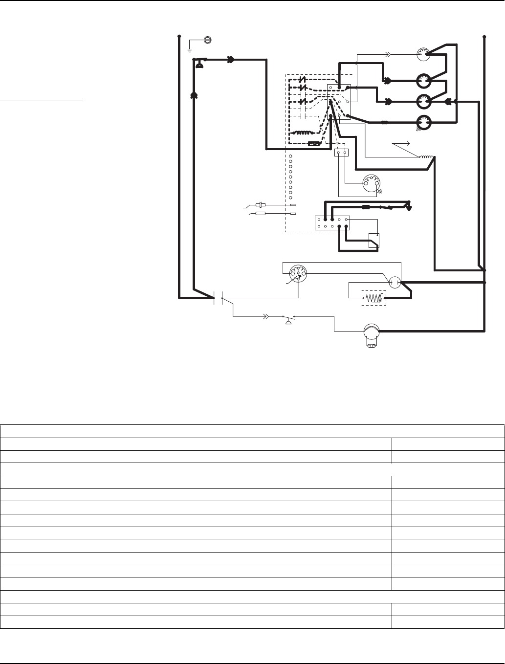
Section 6 Electrical System
Part Number 80-1480-3 6-3
Wiring Diagram Sequence of
Operation
SELF-CONTAINED MODELS
Initial Start-Up or Start-Up After
Automatic Shut-Off
1. WATER PURGE
Before the compressor starts, the
water pump and water dump
solenoid are energized for 45
seconds to purge old water from the
ice machine. This ensures that the
ice-making cycle starts with fresh
water.
The harvest valve(s) is also
energized during the water purge. In
the case of an initial refrigeration
start-up or auto shut-off, it stays on
for an additional
5 seconds (50 seconds total).
When Used - The air compressor
energizes for the last 10 seconds of
the cycle.
Self-Contained — Water Purge
Table 6-1. Self-Contained Models
1. Water Purge (45 Seconds)
Toggle Switch ICE
Bin Switch Closed
Control Board Relays
#1 Water Pump ON
#2 Harvest Valve (Left) ON
#3 Harvest Valve (Right) ON (When Used)
#4 Air Compressor 35 sec. OFF / 10 sec. ON
#5 Water Inlet Valve OFF
#6 Water Dump Valve ON
#7 Contactor Coil Open / OFF
#7A Compressor OFF
#7B Condenser Fan Motor OFF
Safety Controls (Which could stop ice machine operation)
High Pressure Cut-Out Closed
Main Fuse (On Control Board) Closed
SV3137-2
(89) (55)
(88)
High
Pressure
Cutout
Control Board
L1 Ground
(2)
(6)
(5)
(1)
(7)
(4)
L2 or N
Water Valve
Harvest Valve
(20) (21)
(22)
(61)
Dump Valve
Water Pump
(60)
(76) (81)
(75)
(77)
(80)
(57) (98)
(58)
(59)
(42)
Ice Thickness
Probe
Water Level Probe
Trans.
Fuse (7a)
L2
Terminates at
Pin Connection
(99)
Contactor Coil
(56)
Air Compressor
(26)
(25)
Low DC
Voltage
Plug
Bin Switch
Clean
OFF
ICE
(2)
(1)
(6)
(8)
(9) (74)
Compressor
Run Capacitor
(Red)
(Yellow)
Fan Motor
PTCR (45)
(46)
(50)
(51) (85)
Overload
(Black)
(86)
Fan Cycle
Control
L1
Contactor
Contacts
Run Capacitor
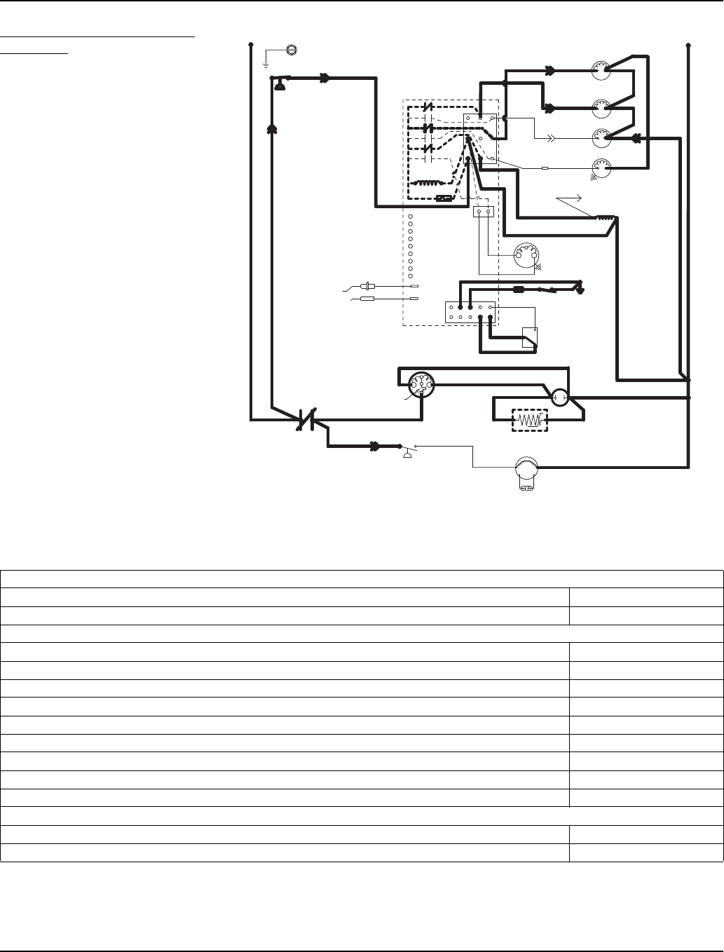
Electrical System Section 6
6-4 Part Number 80-1480-3
2. REFRIGERATION SYSTEM
START-UP
The compressor starts after the 45-
second water purge, and it remains
on throughout the Freeze and
Harvest cycles.
The water fill valve is energized at
the same time as the compressor.
The harvest valve(s) remains on for
the first 5 seconds of the initial
compressor start-up and then shuts
off.
At the same time the compressor
starts, the condenser fan motor (air-
cooled models) is supplied with
power throughout the entire freeze
and harvest sequences.
The fan motor is wired through a fan
cycle pressure control, and may
cycle on and off. (The compressor
and the condenser fan motor are
wired through the contactor. Any time
the contactor coil is energized, the
compressor and fan motor are
supplied with power.)
Self-Contained — Refrigeration System Start-Up
Table 6-2. Self-Contained Models
2. Refrigeration System Start Up (5 Seconds)
Toggle Switch ICE
Bin Switch Closed
Control Board Relays
#1 Water Pump OFF
#2 Harvest Valve (Left) ON
#3 Harvest Valve (Right) ON (When Used)
#4 Air Compressor ON (When Used)
#5 Water Inlet Valve ON
#6 Water Dump Valve OFF
#7 Contactor Coil Closed / ON
#7A Compressor ON
#7B Condenser Fan Motor OFF
Safety Controls (Which could stop ice machine operation)
High Pressure Cut-Out Closed
Main Fuse (On Control Board) Closed
SV3137-4
(89) (55)
(88)
High
Pressure
Cutout
Control Board
L1 Ground
(2)
(6)
(5)
(1)
(7)
(4)
L2 or N
Water Valve
Harvest Valve
(20) (21)
(22)
(61)
Dump Valve
Water Pump
(60)
(76) (81)
(75)
(77) (80)
(57) (98)
(58)
(59)
(42)
Ice Thickness
Probe
Water Level Probe
Trans.
Fuse (7a)
L2
Terminates at
Pin Connection
(99)
Contactor Coil
(56)
Air Compressor
(26)
(25)
Low DC
Voltage
Plug
Bin Switch
Clean
OFF
ICE
(2)
(1)
(6)
(8)
(9) (74)
Compressor Run Capacitor
(Red)
(Yellow)
Fan Motor
PTCR (45)
(46)
(50)
(51) (85)
Overload
(Black)
(86)
Fan Cycle
Control
L1
Contactor
Contacts
Run Capacitor

Section 6 Electrical System
Part Number 80-1480-3 6-5
Freeze Sequence
3. PRE-CHILL
To pre-chill the evaporator, the
compressor runs for 30 seconds (60
seconds initial cycle) prior to water
flow.
The water fill valve remains on until
the water level probe is satisfied.
Self-Contained — Pre-Chill
Table 6-3. Self-Contained Models
3. Pre-Chill (60 Seconds Initial Cycle - 30 Seconds thereafter)
Toggle Switch ICE
Bin Switch Closed
Control Board Relays
#1 Water Pump OFF
#2 Harvest Valve (Left) OFF
#3 Harvest Valve (Right) OFF (When Used)
#4 Air Compressor OFF (When Used)
#5 Water Inlet Valve On
#6 Water Dump Valve OFF
#7 Contactor Coil Closed / ON
#7A Compressor ON
#7B Condenser Fan Motor May Cycle ON / OFF
Safety Controls (Which could stop ice machine operation)
High Pressure Cut-Out Closed
Main Fuse (On Control Board) Closed
SV3137-3
(89) (55)
(88)
High
Pressure
Cutout
Control Board
L1 Ground
(2)
(6)
(5)
(1)
(7)
(4)
L2 or N
Water Valve
Harvest Valve
(20) (21)
(22)
(61)
Dump Valve
Water Pump
(60)
(76) (81)
(75)
(77) (80)
(57) (98)
(58)
(59)
(42)
Ice Thickness
Probe
Water Level Probe
Trans.
Fuse (7a)
L2
Terminates at
Pin Connection
(99)
Contactor Coil
(56)
Air Compressor
(26)
(25)
Low DC
Voltage
Plug
Bin Switch
Clean
OFF
ICE
(2)
(1)
(6)
(8)
(9) (74)
Compressor Run Capacitor
(Red)
(Yellow)
Fan Motor
PTCR (45)
(46)
(50)
(51) (85)
Overload
(Black)
(86)
Fan Cycle
Control
L1
Contactor
Contacts
Run Capacitor
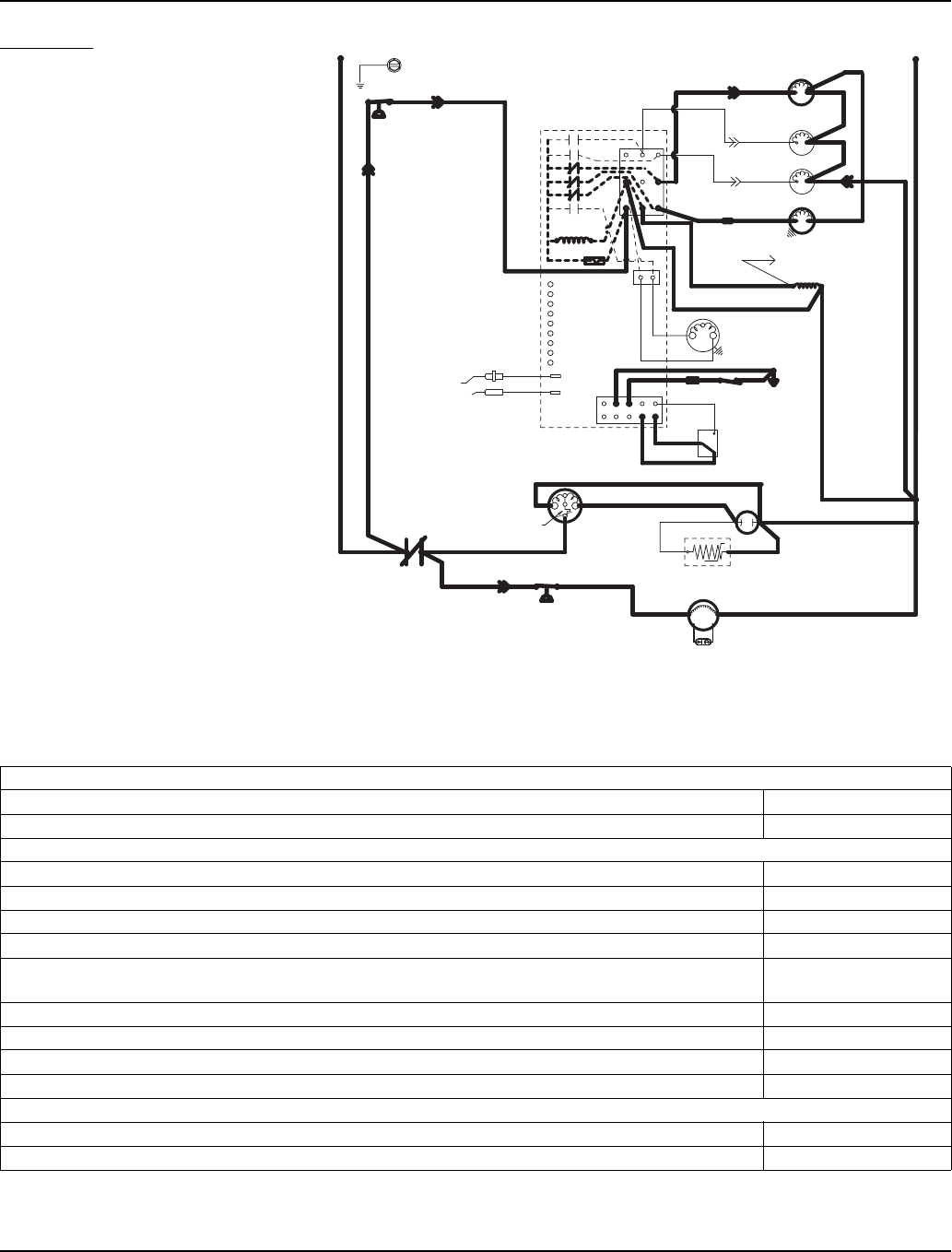
Electrical System Section 6
6-6 Part Number 80-1480-3
4. FREEZE
The water pump starts after the pre-
chill. An even flow of water is directed
across the evaporator and into each
cube cell, where it freezes.
The water fill valve will cycle off then
on one more time to refill the water
trough.
When sufficient ice has formed, the
water flow (not the ice) contacts the
ice thickness probes. After
approximately 10 seconds of
continual contact, a harvest cycle is
initiated.
NOTE: The ice machine cannot
initiate a harvest cycle until a 6-
minute freeze lock has expired.
Self-Contained — Freeze
Table 6-4. Self-Contained Models
4. Freeze (Until 10 Seconds of Water Contact with Ice Thickness Probe)
Toggle Switch ICE
Bin Switch Closed
Control Board Relays
#1 Water Pump ON
#2 Harvest Valve (Left) OFF
#3 Harvest Valve (Right) OFF (When Used)
#4 Air Compressor OFF (When Used)
#5 Water Inlet Valve Cycles OFF, then ON
one more time
#6 Water Dump Valve OFF
#7 Contactor Coil Closed / ON
#7A Compressor ON
#7B Condenser Fan Motor May Cycle ON / OFF
Safety Controls (Which could stop ice machine operation)
High Pressure Cut-Out Closed
Main Fuse (On Control Board) Closed
SV3137-5
(89) (55)
(88)
High
Pressure
Cutout
Control Board
L1 Ground
(2)
(6)
(5)
(1)
(7)
(4)
L2 or N
Water Valve
Harvest Valve
(20) (21)
(22)
(61)
Dump Valve
Water Pump
(60)
(76) (81) (75)
(77) (80)
(57) (98)
(58)
(59)
(42)
Ice Thickness
Probe
Water Level Probe
Trans.
Fuse (7a)
L2
Terminates at
Pin Connection
(99)
Contactor Coil
(56)
Air Compressor
(26)
(25)
Low DC
Voltage
Plug
Bin Switch
Clean
OFF
ICE
(2)
(1)
(6)
(8)
(9) (74)
Compressor Run Capacitor
(Red)
(Yellow)
Fan Motor
PTCR (45)
(46)
(50)
(51) (85)
Overload
(Black)
(86)
Fan Cycle
Control
L1
Contactor
Contacts
Run Capacitor
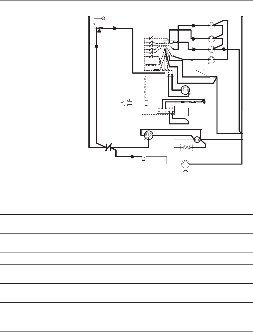
Section 6 Electrical System
Part Number 80-1480-3 6-7
Harvest Sequence
5. WATER PURGE
The harvest valve(s) opens at the
beginning of the water purge to divert
hot refrigerant gas into the
evaporator.
The water pump continues to run,
and the water dump valve energizes
for 45 seconds to purge the water in
the sump trough. The water fill valve
energizes and de-energizes strictly
by time. The water fill valve energizes
for the last 15 seconds of the 45-
second water purge.
After the 45 second water purge, the
water fill valve, water pump and
dump valve de-energize. (Refer to
“Water Purge Adjustment” for
details.)
The air compressor (when used) will
energize after 35 seconds.
Self-Contained — Water Purge
Table 6-5. Self-Contained Models
5. Water Purge (45 Seconds)
Toggle Switch ICE
Bin Switch Closed
Control Board Relays
#1 Water Pump ON
#2 Harvest Valve (Left) ON
#3 Harvest Valve (Right) ON (When Used)
#4 Air Compressor ON; after 35 seconds
#5 Water Inlet Valve 30 seconds OFF,
15 seconds ON
#6 Water Dump Valve ON
#7 Contactor Coil Closed / ON
#7A Compressor ON
#7B Condenser Fan Motor OFF; May Cycle ON
Safety Controls (Which could stop ice machine operation)
High Pressure Cut-Out Closed
Main Fuse (On Control Board) Closed
SV3137-6
(89) (55)
(88)
High
Pressure
Cutout
Control Board
L1 Ground
(2)
(6)
(5)
(1)
(7)
(4)
L2 or N
Water Valve
Harvest Valve
(20) (21)
(22)
(61)
Dump Valve
Water Pump
(60)
(76) (81)
(75)
(77) (80)
(57) (98)
(58)
(59)
(42)
Ice Thickness
Probe
Water Level Probe
Trans.
Fuse (7a)
L2
Terminates at
Pin Connection
(99)
Contactor Coil
(56)
Air Compressor
(26)
(25)
Low DC
Voltage
Plug
Bin Switch
Clean
OFF
ICE
(2)
(1)
(6)
(8)
(9) (74)
Compressor Run Capacitor
(Red)
(Yellow)
Fan Motor
PTCR (45)
(46)
(50)
(51) (85)
Overload
(Black)
(86)
Fan Cycle
Control
L1
Contactor
Contacts
Run Capacitor
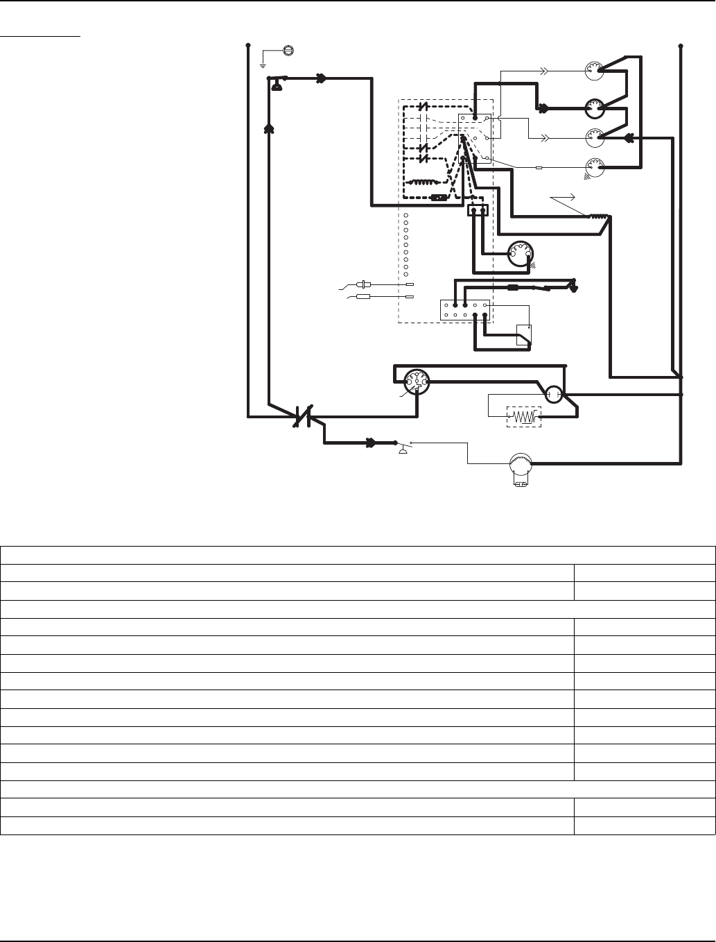
Electrical System Section 6
6-8 Part Number 80-1480-3
6. HARVEST
The harvest valve(s) remains open
and the refrigerant gas warms the
evaporator. This causes the cubes to
slide, as a sheet, off the evaporator
and into the storage bin.
The sliding sheet of cubes swings the
water curtain out, opening the bin
switch. This momentary opening and
closing of the bin switch terminates
the Harvest Cycle and returns the ice
machine to the Freeze Cycle (steps
3-4).
The air compressor (when used)
remains energized throughout the
entire harvest cycle. The air
compressor will automatically
energize after 60 seconds when the
harvest cycle time exceeded 75
seconds in the previous cycle.
Table 6-6. Self-Contained Models
6. Harvest (Until Bin Switch Activation)
Toggle Switch ICE
Bin Switch Closed
Control Board Relays
#1 Water Pump OFF
#2 Harvest Valve (Left) ON
#3 Harvest Valve (Right) ON (When Used)
#4 Air Compressor ON (When Used)
#5 Water Inlet Valve OFF
#6 Water Dump Valve OFF
#7 Contactor Coil Closed / ON
#7A Compressor ON
#7B Condenser Fan Motor OFF; May Cycle ON
Safety Controls (Which could stop ice machine operation)
High Pressure Cut-Out Closed
Main Fuse (On Control Board) Closed
SV3137-7
(89) (55)
(88)
High
Pressure
Cutout
Control Board
L1 Ground
(2)
(6)
(5)
(1)
(7)
(4)
L2 or N
Water Valve
Harvest Valve
(20) (21)
(22)
(61)
Dump Valve
Water Pump
(60)
(76) (81) (75)
(77) (80)
(57) (98)
(58)
(59)
(42)
Ice Thickness
Probe
Water Level Probe
Trans.
Fuse (7a)
L2
Terminates at
Pin Connection
(99)
Contactor Coil
(56)
Air Compressor
(26)
(25)
Low DC
Voltage
Plug
Bin Switch
Clean
OFF
ICE
(2)
(1)
(6)
(8)
(9) (74)
Compressor
Run Capacitor
(Red)
(Yellow)
Fan Motor
PTCR (45)
(46)
(50)
(51) (85)
Overload
(Black)
(86)
Fan Cycle
Control
L1
Contactor
Contacts
Run Capacitor
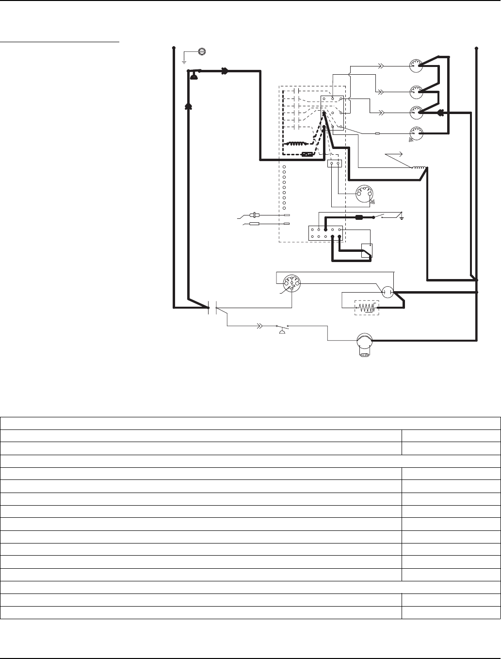
Section 6 Electrical System
Part Number 80-1480-3 6-9
Automatic Shut-Off
7. AUTOMATIC SHUT-OFF
When the storage bin is full at the
end of a harvest cycle, the sheet of
cubes fails to clear the water curtain
and holds it open. After the water
curtain is held open for 30 seconds,
the ice machine shuts off.
The ice machine remains off until
enough ice is removed from the
storage bin to allow the sheet of
cubes to drop clear of the water
curtain. As the water curtain swings
back to the operating position, the bin
switch closes and the ice machine
restarts (steps 1-2), provided the 3
minute delay period is complete.
NOTE: The ice machine must remain
off for 3 minutes before it can
automatically restart.
Self-Contained — Automatic Shut-Off
Table 6-7. Self-Contained Models
7. Automatic Shut-Off (Until Bin Switch Closes)
Toggle Switch ICE
Bin Switch Open
Control Board Relays
#1 Water Pump OFF
#2 Harvest Valve (Left) OFF
#3 Harvest Valve (Right) OFF (When Used)
#4 Air Compressor OFF (When Used)
#5 Water Inlet Valve OFF
#6 Water Dump Valve OFF
#7 Contactor Coil Open / OFF
#7A Compressor OFF
#7B Condenser Fan Motor OFF
Safety Controls (Which could stop ice machine operation)
High Pressure Cut-Out Closed
Main Fuse (On Control Board) Closed
SV3137-1
(89) (55)
(88)
High
Pressure
Cutout
Control Board
L1 Ground
(2)
(6)
(5)
(1)
(7)
(4)
L2 or N
Water Valve
Harvest Valve
(20) (21)
(22)
(61)
Dump Valve
Water Pump
(60)
(76) (81) (75)
(77) (80)
(57) (98)
(58)
(59)
(42)
Ice Thickness
Probe
Water Level Probe
Trans.
Fuse (7a)
L2
Terminates at
Pin Connection
(99)
Contactor Coil
(56)
Air Compressor
(26)
(25)
Low DC
Voltage
Plug
Bin Switch
Clean
OFF
ICE
(2)
(1)
(6)
(8)
(9) (74)
Compressor
Run Capacitor
(Red)
(Yellow)
Fan Motor
PTCR (45)
(46)
(50)
(51) (85)
Overload
(Black)
(86)
Fan Cycle
Control
L1
Contactor
Contacts
Run Capacitor

Electrical System Section 6
6-10 Part Number 80-1480-3
THIS PAGE INTENTIONALLY LEFT BLANK
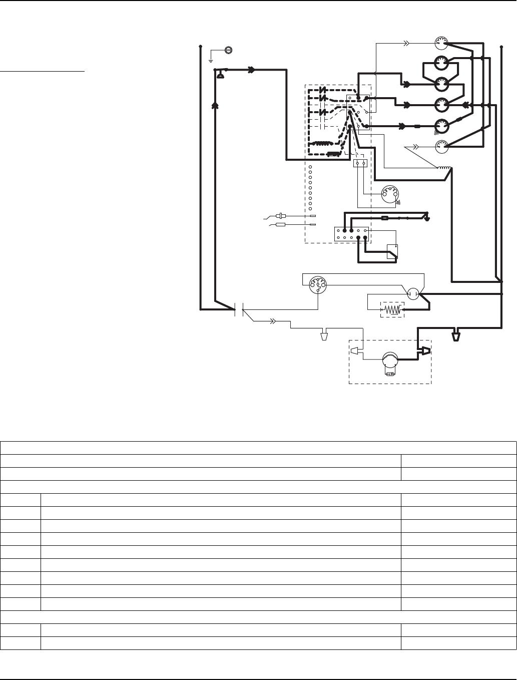
Section 6 Electrical System
Part Number 80-1480-3 6-11
REMOTE MODELS
Initial Start-Up Or Start-Up After
Automatic Shut-Off
1. WATER PURGE
Before the compressor starts, the
water pump and water dump
solenoid are energized for 45
seconds to purge old water from the
ice machine. This ensures that the
ice-making cycle starts with fresh
water.
NOTE: The harvest valve and
harvest pressure regulating (HPR)
solenoid valve are also energized
during the water purge. In the case of
an initial refrigeration start-up or auto
shut-off, they stay on for an additional
5 seconds (50 seconds total).
Remote - Water Purge
Table 6-8. Remote Models
SV3158-1
Water Valve
Harvest Valve
Dump Valve
Water Pump
(20) (21)
(79)
(74)
(61)
(60)
(57) (98)
(22)
(76)
(81)
(77) (80)
(26)
(25)
(58)
(59)
Contactor Coil
(56)
L2
Air Compressor
(8)
(83)
(88)
(22)
(75)
Liquid Line
Solenoid
HPR Valve
(55)
(89)
(9)
(78)
(82)
(42)
(50)
(45)
(46)
(F2)
(F1)
(51)
Black
Red
Yellow
(L1)
(L1) (L2)
(6)
(1)
(2)
Remote Fan Motor Remote
Condenser
Run Capacitor
Contactor
Contacts
Compressor
Ice Thickness
Probe
Water Level
Probe
High Pressure
Cut-out
Ground
Run
Cap.
OFF
Clean
ON
Bin Switch
Trans
Fuse 7A
Control Board
(2)
(6)
(5)
(1)
(7)
(4)
PTCR
Low DC
Voltage
Plug
(99)
1. Water Purge (45 Seconds)
Toggle Switch ICE
Bin Switch Closed
Control Board Relays
#1 Water Pump ON
#2 Harvest Valve (Left) / HPR Valve ON
#3 Harvest Valve (Right) ON (When Used)
#4 Air Compressor 35 sec. OFF / 10 sec. ON
#5 Water Inlet Valve OFF
#6 Water Dump Valve ON
#7 Contactor Coil / Liquid Line Solenoid Open / OFF
#7A Compressor OFF
#7B Condenser Fan Motor OFF
Safety Controls (Which could stop ice machine operation)
High Pressure Cut-Out Closed
Main Fuse (On Control Board) Closed
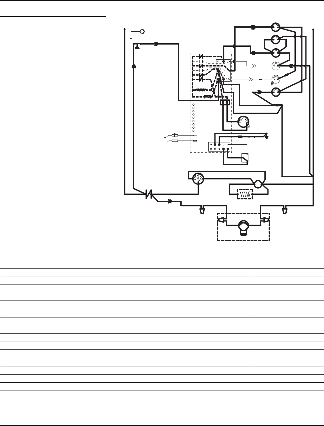
Electrical System Section 6
6-12 Part Number 80-1480-3
2. REFRIGERATION SYSTEM START-UP
The compressor, remote condenser fan motor
and liquid line solenoid valve energize after
the 45-second water purge, and remain on
throughout the Freeze and Harvest cycles.
The water fill valve is energized at the same
time as the compressor. It remains on until the
water level sensor closes for 3 continuous
seconds.
The harvest valve and harvest pressure
regulating (HPR) solenoid valve remain on for
the first 5 seconds of the initial compressor
start-up.
NOTE: (The compressor and the condenser
fan motor are wired through the contactor. Any
time the contactor coil is energized, these
components are supplied with power.)
Table 6-9. Remote Models Remote — Refrigeration System Start-Up
2. Refrigeration System Start Up (5 Seconds)
Toggle Switch ICE
Bin Switch Closed
Control Board Relays
#1 Water Pump OFF
#2 Harvest Valve (Left) / HPR Valve ON
#3 Harvest Valve (Right) ON (When Used)
#4 Air Compressor ON (When Used)
#5 Water Inlet Valve ON
#6 Water Dump Valve OFF
#7 Contactor Coil / Liquid Line Solenoid Closed / ON
#7A Compressor ON
#7B Condenser Fan Motor ON
Safety Controls (Which could stop ice machine operation)
High Pressure Cut-Out Closed
Main Fuse (On Control Board) Closed
SV3158-2
Water Valve
Harvest Valve
Dump Valve
Water Pump
(20) (21)
(79)
(74)
(61)
(60)
(57) (98)
(22)
(76)
(81)
(77) (80)
(26)
(25)
(58)
(59)
Contactor Coil
(56)
L2
Air Compressor
(8)
(83)
(88)
(22)
(75)
Liquid Line
Solenoid
HPR Valve
(55)
(89)
(9)
(78)
(82)
(42)
(50)
(45)
(46)
(F2)
(F1)
(51)
Black
Red
Yellow
(L1)
(L1) (L2)
(6)
(1)
(2)
Remote Fan Motor Remote
Condenser
Run Capacitor
Contactor
Contacts
Compressor
Ice Thickness
Probe
Water Level
Probe
High Pressure
Cut-out
Ground
Run
Cap.
OFF
Clean
ON
Bin Switch
Trans
Fuse 7A
Control Board
(2)
(6)
(5)
(1)
(7)
(4)
PTCR
Low DC
Voltage
Plug
(99)
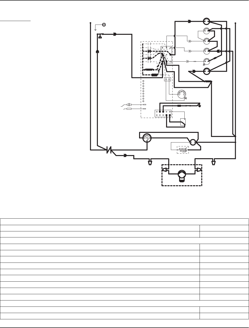
Section 6 Electrical System
Part Number 80-1480-3 6-13
Freeze Sequence
3. PRE-CHILL
To pre-chill the evaporator, the
compressor runs for 30 seconds (60
seconds initial cycle) prior to water
flow.
NOTE: The water fill valve remains
on until the water level probe is
satisfied.
Remote — Pre-Chill
Table 6-10. Remote Models
3. Pre-Chill (60 Seconds Initial Cycle - 30 Seconds thereafter)
Toggle Switch ICE
Bin Switch Closed
Control Board Relays
#1 Water Pump OFF
#2 Harvest Valve (Left) / HPR Valve OFF
#3 Harvest Valve (Right) OFF (When Used)
#4 Air Compressor OFF (When Used
#5 Water Inlet Valve ON
#6 Water Dump Valve OFF
#7 Contactor Coil / Liquid Line Solenoid Closed / ON
#7A Compressor ON
#7B Condenser Fan Motor May Cycle ON / OFF
Safety Controls (Which could stop ice machine operation)
High Pressure Cut-Out Closed
Main Fuse (On Control Board) Closed
SV3158-3
Water Valve
Harvest Valve
Dump Valve
Water Pump
(20) (21)
(79)
(74)
(61)
(60)
(57) (98)
(22)
(76)
(81)
(77) (80)
(26)
(25)
(58)
(59)
Contactor Coil
(56)
L2
Air Compressor
(8)
(83)
(88)
(22)
(75)
Liquid Line
Solenoid
HPR Valve
(55)
(89)
(9)
(78)
(82)
(42)
(50)
(45)
(46)
(F2)
(F1)
(51)
Black
Red
Yellow
(L1)
(L1) (L2)
(6)
(1)
(2)
Remote Fan Motor Remote
Condenser
Run Capacitor
Contactor
Contacts
Compressor
Ice Thickness
Probe
Water Level
Probe
High Pressure
Cut-out
Ground
Run
Cap.
OFF
Clean
ON
Bin Switch
Trans
Fuse 7A
Control Board
(2)
(6)
(5)
(1)
(7)
(4)
PTCR
Low DC
Voltage
Plug
(99)
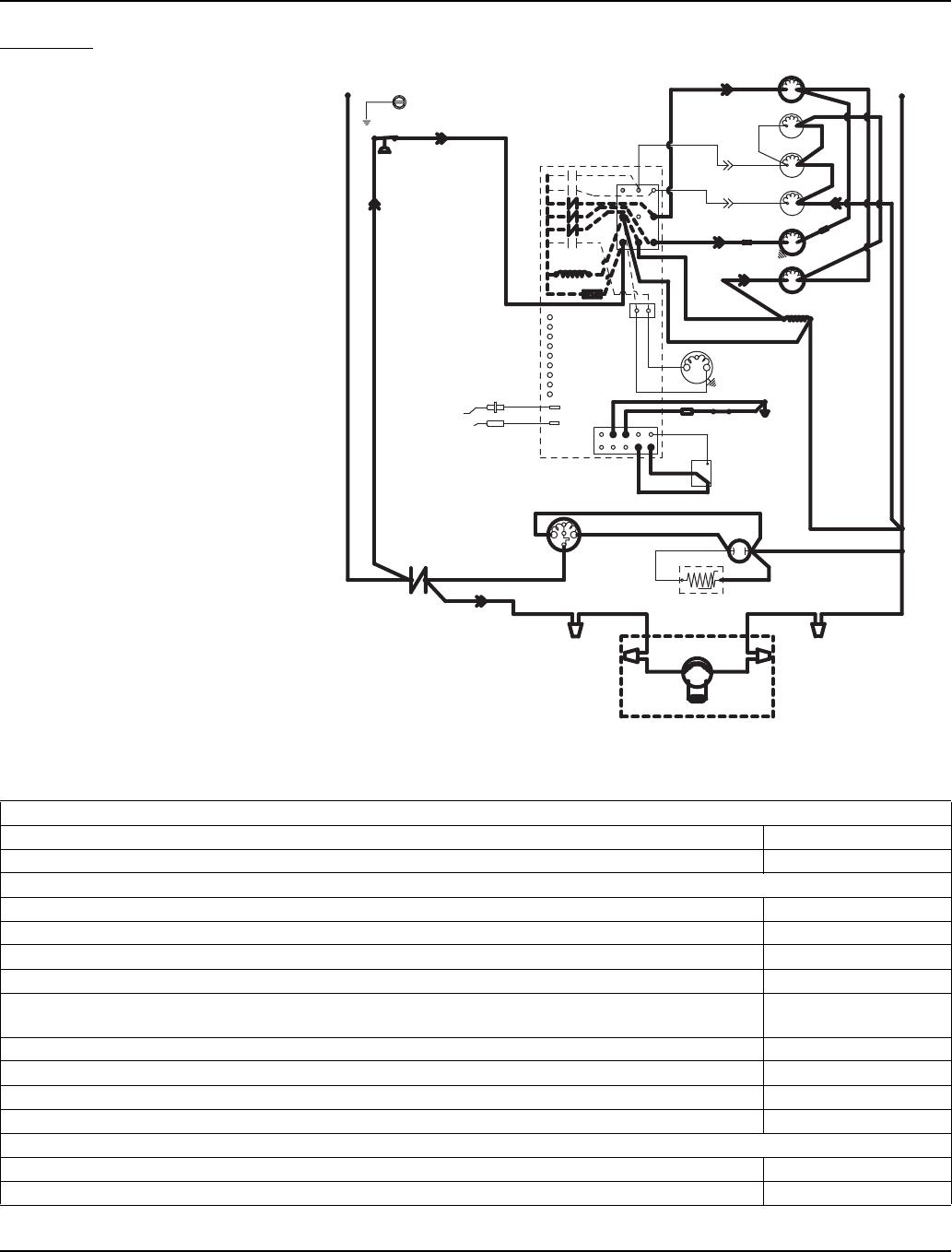
Electrical System Section 6
6-14 Part Number 80-1480-3
4. FREEZE
The water pump starts after the pre-
chill. An even flow of water is directed
across the evaporator and into each
cube cell, where it freezes.
The water fill valve will cycle off then
on one more time to refill the water
trough.
When sufficient ice has formed, the
water flow (not the ice) contacts the
ice thickness probes. After
approximately 10 seconds of
continual contact, a harvest cycle is
initiated.
NOTE: The ice machine cannot
initiate a harvest cycle until a 6-
minute freeze lock has expired.
Table 6-11. Remote Models Remote — Freeze
4. Freeze (Until 10 Seconds of Water Contact with Ice Thickness Probe)
Toggle Switch ICE
Bin Switch Closed
Control Board Relays
#1 Water Pump ON
#2 Harvest Valve (Left) / HPR Valve OFF
#3 Harvest Valve (Right) OFF (When Used)
#4 Air Compressor OFF (When Used)
#5 Water Inlet Valve Cycles OFF, then ON
one more time
#6 Water Dump Valve OFF
#7 Contactor Coil / Liquid Line Solenoid Closed / ON
#7A Compressor ON
#7B Condenser Fan Motor ON
Safety Controls (Which could stop ice machine operation)
High Pressure Cut-Out Closed
Main Fuse (On Control Board) Closed
SV3158-4
Water Valve
Harvest Valve
Dump Valve
Water Pump
(20) (21)
(79)
(74)
(61)
(60)
(57) (98)
(22)
(76)
(81)
(77) (80)
(26)
(25)
(58)
(59)
Contactor Coil
(56)
L2
Air Compressor
(8)
(83)
(88)
(22)
(75)
Liquid Line
Solenoid
HPR Valve
(55)
(89)
(9)
(78)
(82)
(42)
(50)
(45)
(46)
(F2)
(F1)
(51)
Black
Red
Yellow
(L1)
(L1) (L2)
(6)
(1)
(2)
Remote Fan Motor
Remote
Condenser
Run Capacitor
Contactor
Contacts
Compressor
Ice Thickness
Probe
Water Level
Probe
High Pressure
Cut-out
Ground
Run
Cap.
OFF
Clean
ON
Bin Switch
Trans
Fuse 7A
Control Board
(2)
(6)
(5)
(1)
(7)
(4)
PTCR
Low DC
Voltage
Plug
(99)
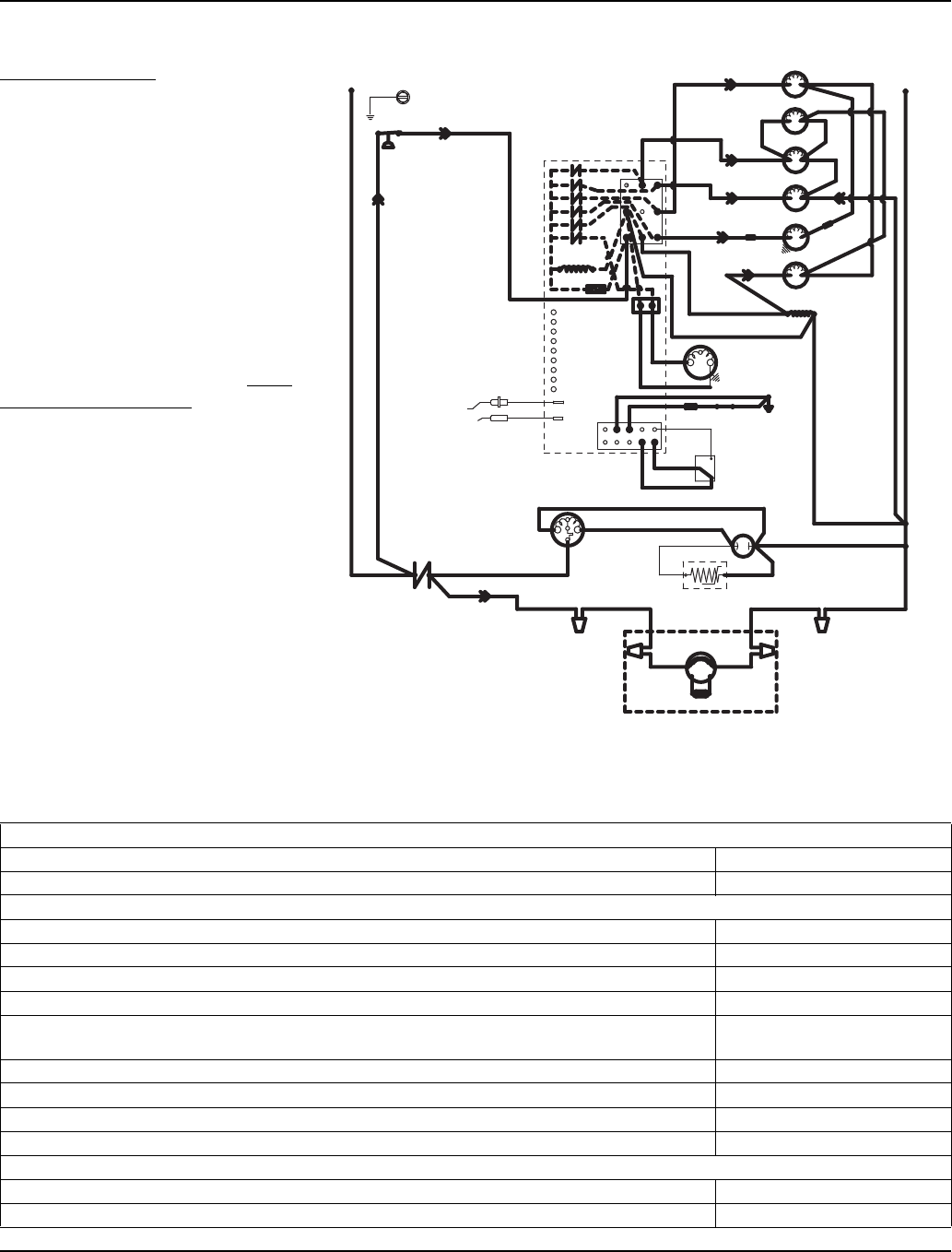
Section 6 Electrical System
Part Number 80-1480-3 6-15
Harvest Sequence
5. WATER PURGE
The harvest valve and HPR solenoid
also open at the beginning of the
water purge to divert hot refrigerant
gas into the evaporator.
The water pump continues to run,
and the water dump valve energizes
for 45 seconds to purge the water in
the sump trough. The water fill valve
energizes (turns on) and de-
energizes (turns off) strictly by time.
The water fill valve energizes for the
last 15 seconds of the 45-second
water purge. The water purge must
be at the factory setting of 45
seconds for the fill valve to energize
during the last 15 seconds of the
Water Purge. If set at less than 45
seconds the water fill valve does not
energize during the water purge.
NOTE: After the 45 second water
purge, the water fill valve, water
pump and dump valve de-energize.
(Refer to “Water Purge Adjustment”
for details.)
Remote — Water Purge
Table 6-12. Remote Models
5. Water Purge (45 Seconds)
Toggle Switch ICE
Bin Switch Closed
Control Board Relays
#1 Water Pump ON
#2 Harvest Valve (Left) / HPR Valve ON
#3 Harvest Valve (Right) ON (When Used)
#4 Air Compressor ON; after 35 seconds
#5 Water Inlet Valve 30 seconds OFF,
15 seconds ON
#6 Water Dump Valve ON
#7 Contactor Coil / Liquid Line Solenoid Closed / ON
#7A Compressor ON
#7B Condenser Fan Motor ON
Safety Controls (Which could stop ice machine operation)
High Pressure Cut-Out Closed
Main Fuse (On Control Board) Closed
SV3158-5
Water Valve
Harvest Valve
Dump Valve
Water Pump
(20) (21)
(79)
(74)
(61)
(60)
(57) (98)
(22)
(76)
(81)
(77) (80)
(26)
(25)
(58)
(59)
Contactor Coil
(56)
L2
Air Compressor
(8)
(83)
(88)
(22)
(75)
Liquid Line
Solenoid
HPR Valve
(55)
(89)
(9)
(78)
(82)
(42)
(50)
(45)
(46)
(F2)
(F1)
(51)
Black
Red
Yellow
(L1)
(L1) (L2)
(6)
(1)
(2)
Remote Fan Motor
Remote
Condenser
Run Capacitor
Contactor
Contacts
Compressor
Ice Thickness
Probe
Water Level
Probe
High Pressure
Cut-out
Ground
Run
Cap.
OFF
Clean
ON
Bin Switch
Trans
Fuse 7A
Control Board
(2)
(6)
(5)
(1)
(7)
(4)
PTCR
Low DC
Voltage
Plug
(99)
SV3158-6
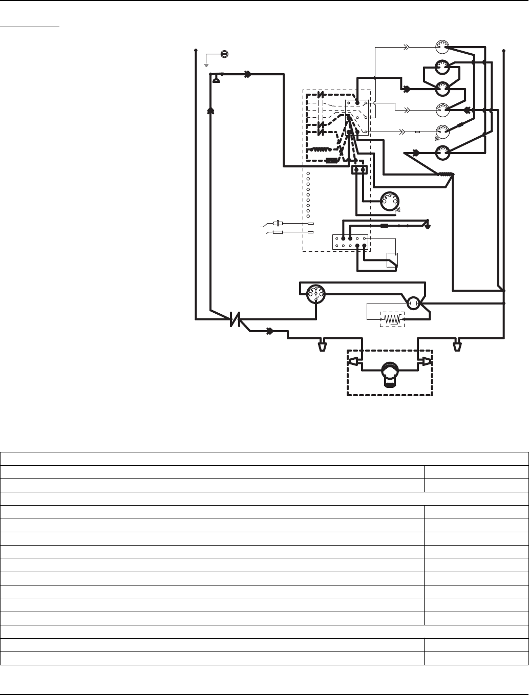
Electrical System Section 6
6-16 Part Number 80-1480-3
6. HARVEST
The harvest valve(s) and HPR
solenoid valve remain open, allowing
refrigerant gas to warm the
evaporator. This causes the cubes to
slide, as a sheet, off the evaporator
and into the storage bin.
The sliding sheet of cubes swings the
water curtain out, opening the bin
switch. This momentary opening and
closing of the bin switch terminates
the Harvest Cycle and returns the ice
machine to the Freeze Cycle (steps
3-4).
The air compressor (when used)
energizes after 35 seconds into the
harvest cycle. The air compressor
will automatically energize after 60
seconds when the harvest cycle time
exceeded 75 seconds in the previous
cycle.
Remote — Harvest
Table 6-13. Remote Models
6. Harvest (Until Bin Switch Activation)
Toggle Switch ICE
Bin Switch Closed
Control Board Relays
#1 Water Pump OFF
#2 Harvest Valve (Left) / HPR Valve ON
#3 Harvest Valve (Right) ON (When Used)
#4 Air Compressor ON (When Used)
#5 Water Inlet Valve OFF
#6 Water Dump Valve OFF
#7 Contactor Coil / Liquid Line Solenoid Closed / ON
#7A Compressor ON
#7B Condenser Fan Motor ON
Safety Controls (Which could stop ice machine operation)
High Pressure Cut-Out Closed
Main Fuse (On Control Board) Closed
Water Valve
Harvest Valve
Dump Valve
Water Pump
(20) (21)
(79)
(74)
(61)
(60)
(57) (98)
(22)
(76)
(81)
(77) (80)
(26)
(25)
(58)
(59)
Contactor Coil
(56)
L2
Air Compressor
(8)
(83)
(88)
(22)
(75)
Liquid Line
Solenoid
HPR Valve
(55)
(89)
(9)
(78)
(82)
(42)
(50)
(45)
(46)
(F2)
(F1)
(51)
Black
Red
Yellow
(L1)
(L1) (L2)
(6)
(1)
(2)
Remote Fan Motor
Remote
Condenser
Run Capacitor
Contactor
Contacts
Compressor
Ice Thickness
Probe
Water Level
Probe
High Pressure
Cut-out
Ground
Run
Cap.
OFF
Clean
ON
Bin Switch
Trans
Fuse 7A
Control Board
(2)
(6)
(5)
(1)
(7)
(4)
PTCR
Low DC
Voltage
Plug
(99)
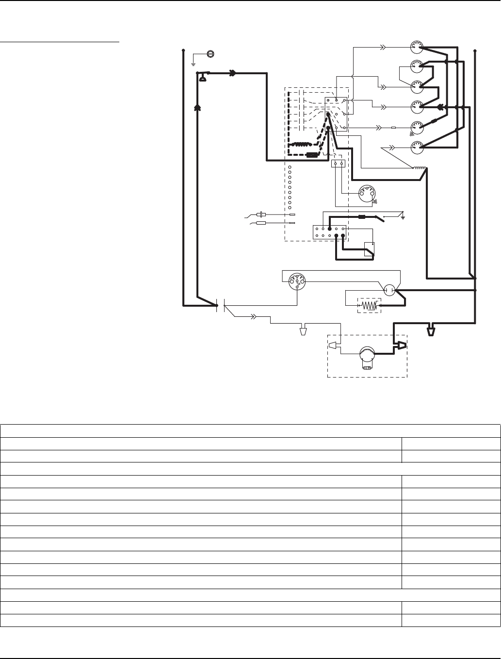
Section 6 Electrical System
Part Number 80-1480-3 6-17
Automatic Shut-Off
7. AUTOMATIC SHUT-OFF
If the storage bin is full at the end of a
harvest cycle, the sheet of cubes fails
to clear the water curtain and holds it
open. After the water curtain is held
open for 30 seconds, the ice machine
shuts off.
The ice machine remains off until
enough ice is removed from the
storage bin to allow the sheet of
cubes to drop clear of the water
curtain. As the water curtain swings
back to the operating position, the bin
switch closes and the ice machine
restarts.
NOTE: The ice machine must remain
off for 3 minutes before it can
automatically restart.
Remote — Automatic Shut-Off
Table 6-14. Remote Models
7. Automatic Shut-Off (Until Bin Switch Closes)
Toggle Switch ICE
Bin Switch Open
Control Board Relays
#1 Water Pump OFF
#2 Harvest Valve (Left) / HPR Valve OFF
#3 Harvest Valve (Right) OFF (When Used)
#4 Air Compressor OFF (When Used)
#5 Water Inlet Valve OFF
#6 Water Dump Valve OFF
#7 Contactor Coil / Liquid Line Solenoid Open / OFF
#7A Compressor OFF
#7B Condenser Fan Motor OFF
Safety Controls (Which could stop ice machine operation)
High Pressure Cut-Out Closed
Main Fuse (On Control Board) Closed
SV3158-7
Water Valve
Harvest Valve
Dump Valve
Water Pump
(20) (21)
(79)
(74)
(61)
(60)
(57) (98)
(22)
(76)
(81)
(77) (80)
(26)
(25)
(58)
(59)
Contactor Coil
(56)
L2
Air Compressor
(8)
(83)
(88)
(22)
(75)
Liquid Line
Solenoid
HPR Valve
(55)
(89)
(9)
(78)
(82)
(42)
(50)
(45)
(46)
(F2)
(F1)
(51)
Black
Red
Yellow
(L1)
(L1) (L2)
(6)
(1)
(2)
Remote Fan Motor
Remote
Condenser
Run Capacitor
Contactor
Contacts
Compressor
Ice Thickness
Probe
Water Level
Probe
High Pressure
Cut-out
Ground
Run
Cap.
OFF
Clean
ON
Bin Switch
Trans
Fuse 7A
Control Board
(2)
(6)
(5)
(1)
(7)
(4)
PTCR
Low DC
Voltage
Plug
(99)

Electrical System Section 6
6-18 Part Number 80-1480-3
Wiring Diagrams
The following pages contain electrical wiring diagrams. Be sure you are referring to the correct diagram for the ice
machine which you are servicing.
WIRING DIAGRAM LEGEND
The following symbols are used on all of the wiring diagrams:
* Internal Compressor Overload
(Some models have external compressor overloads)
** Fan Motor Run Capacitor
(Some models do not incorporate fan motor run capacitor)
TB Terminal Board Connection
(Terminal board numbers are printed on the actual terminal board)
( ) Wire Number Designation
(The number is marked at each end of the wire)
—>>— Multi-Pin Connection
(Electrical Box Side) —>>— (Compressor Compartment Side)
!
Warning
Always disconnect power before working on electrical circuitry.
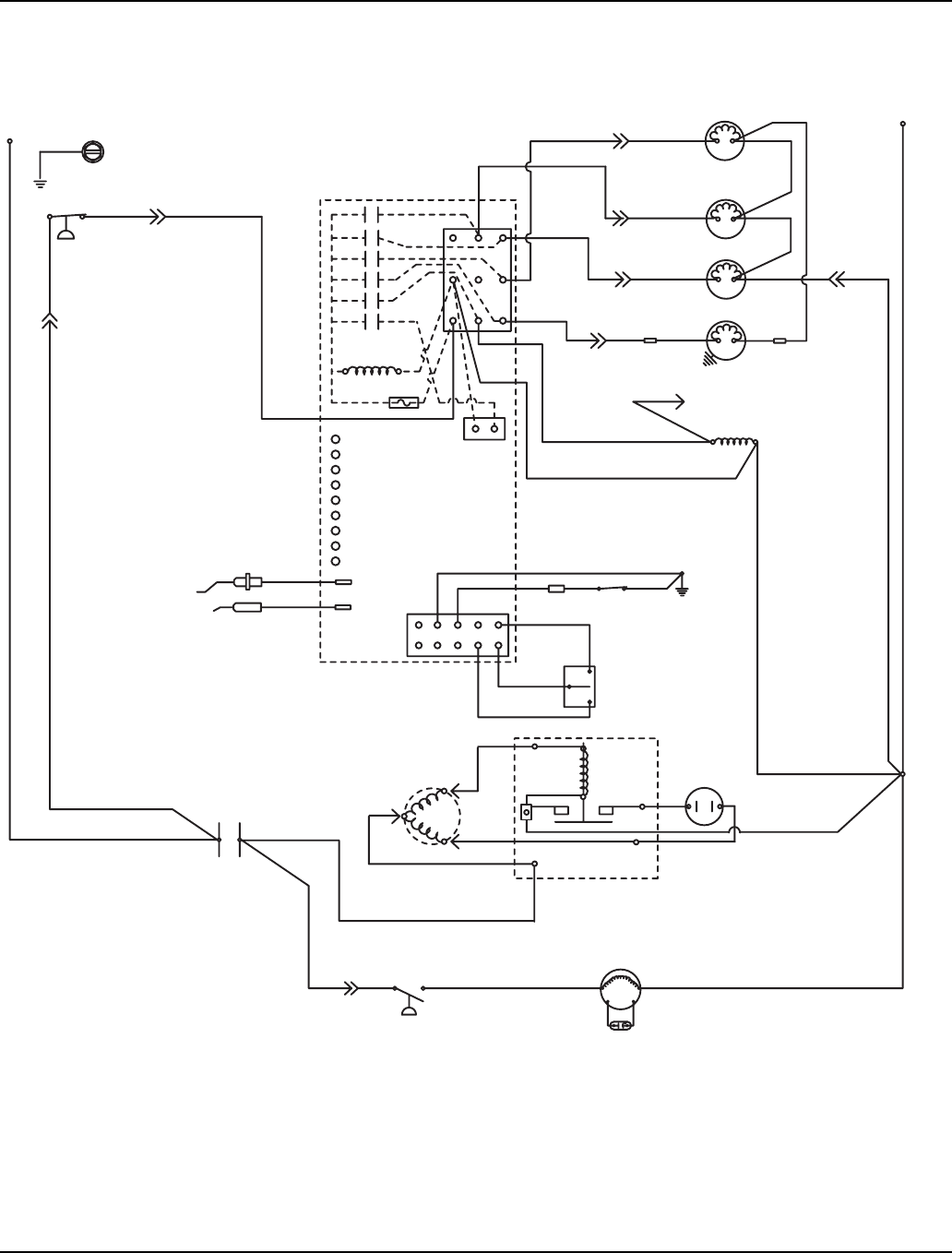
Section 6 Electrical System
Part Number 80-1480-3 6-19
S320 SELF CONTAINED- 1 PHASE
(48)
R
S
C
CLEAN
OFF
ICE
BIN
SWITCH
LOW D.C.
VOLTAGE
PLUG
CONTACTOR
COIL
(56)
TERMINATES AT
PIN CONNECTION
(74)
PUMP
WATER
(99)
(98)
(58)
FUSE (7A)
TRANS.
ICE THICKNESS
PROBE
WATER LEVEL
PROBE
SOLENOID
(57)
DUMP (81)
(75)
(76)
HARVEST
SOLENOID
(80)
(77)
VALVE
WATER
(60)
(61) (22)
(21)
(7)
(2)
(1)
(6)
(5)
HIGH PRESSURE
CUTOUT
(55)
L2 OR N
SEE SERIAL PLATE FOR VOLTAGE
L1
(89)
(88)
(20)
(59)
CLEAN
LEFT BIN
RIGHT BIN
RMT BIN
WTR PROBE
ICE PROBE
HARV
SL-1
SL-2
(6)
(2) (1)
(9)
(8)
(42)
CONTROL BOARD
(4)
(85)
(51)
CONTACTOR
CONTACTS
L1
FAN CYCLE CONTROL
RUN CAPACITOR**
FAN MOTOR
(AIR COOLED ONLY)
(49)
START
CAPACITOR
CURRENT
RELAY
11
12
13
10
14
GROUND
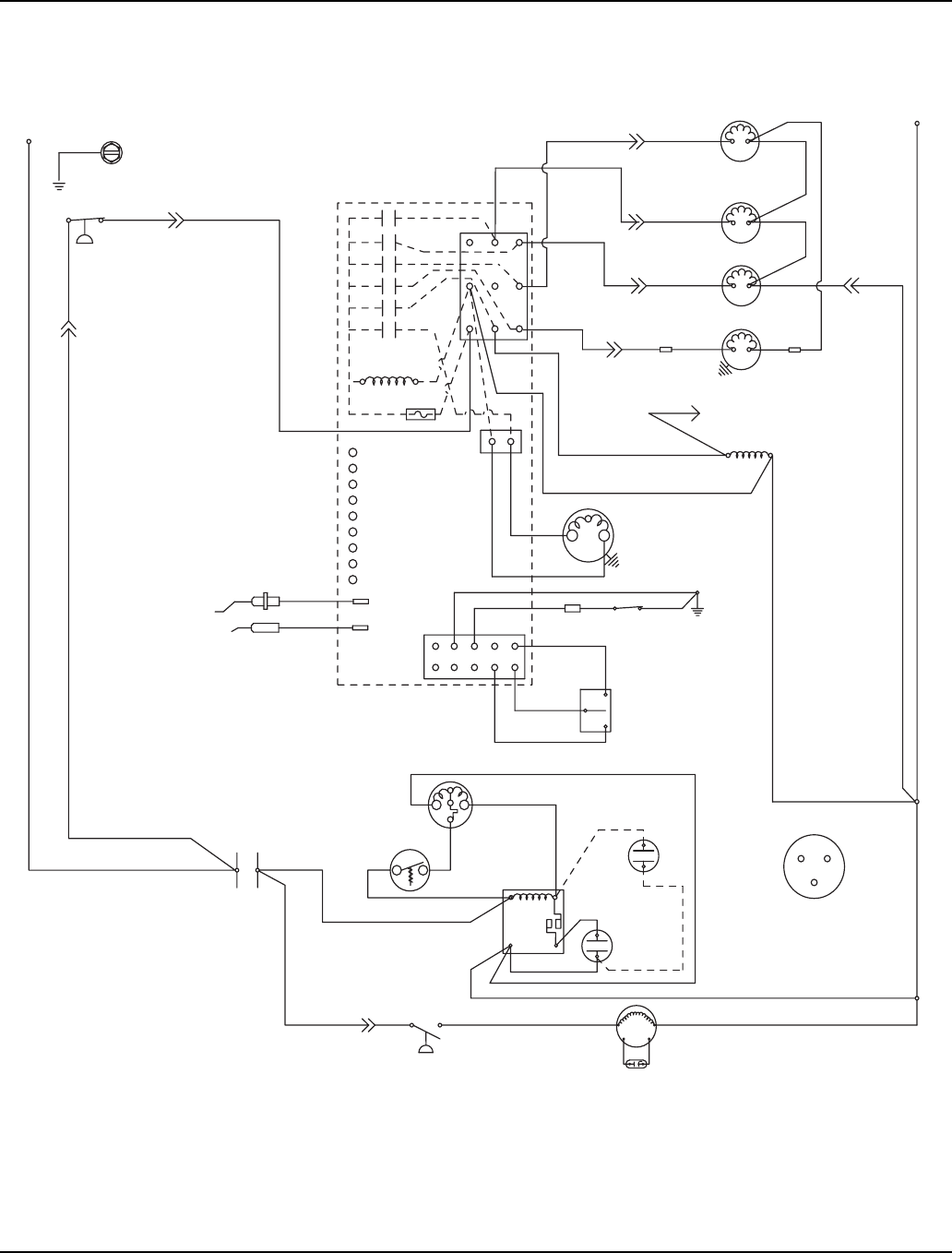
Electrical System Section 6
6-20 Part Number 80-1480-3
S300/S420/S450- SELF CONTAINED - 1 PHASE
(89) (55)
(88)
(42)
High Pressure
Cutout
Water Valve
Harvest Valve
Dump Valve
Water Pump
Terminates at
Pin Connection
(20) (21)
(22)
(74)
Ice Thickness
Probe
Water Level Probe
Control
Board
(61)
(60)
(57) (98)
(99)
(76)
(81)
(75)
(77)
(80)
(26)
(25)
(58)
(59)
Contactor
Coil
(56)
Trans.
Fuse (7a)
Low DC
Voltage
Plug
L1
(51)
(85) (86)
Fan Cycle
Control
Fan Motor
Run Capacitor
Compressor Run
Capacitor
(50)
(45)
L2 or N
L1
Ground
(2)
(6)
(5)
(1)
(7)
(4)
L2
Air Compressor
(When Used)
Bin Switch
Clean
OFF
ICE
(2)
(1)
(6)
(8)
(9)
Overload
Contactor
Contacts
(46)
(99)
(49)
(47)
(44)
(52)
(53)
(48)
52
1
4
S
C
R
S
R
C
Compressor
Terminal Layout
Viewed from End of
Compressor
Clean
Left Bin
Right Bin
Wtr Probe
Rmt Bin
Ice Probe
Harvest
SL-2
SL-1
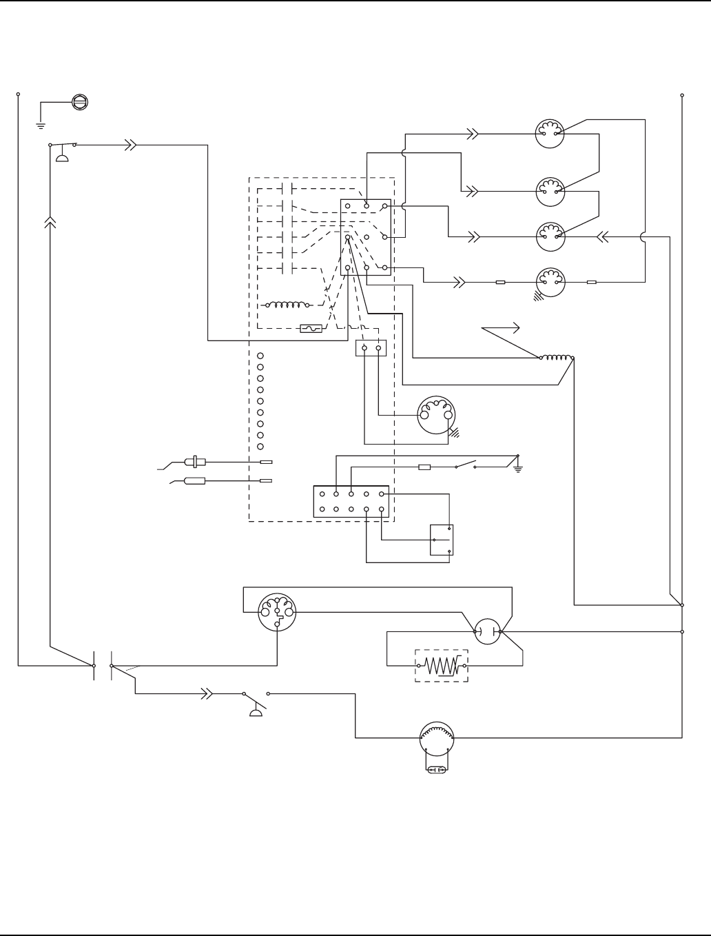
Section 6 Electrical System
Part Number 80-1480-3 6-21
S500/S600/S850/S1000/S1200 - SELF CONTAINED - 1 PHASE
SV3130
(89) (55)
(88)
(42)
High Pressure
Cutout
Water Valve
Harvest Valve
Dump Valve
Water Pump
Terminates at
Pin Connection
(20) (21)
(22)
(74)
Ice Thickness
Probe
Water Level Probe
Control
Board
(61)
(60)
(57) (98)
(99)
(76)
(81) (75)
(77)
(80)
(26)
(25)
(58)
(59)
Contactor
Coil
(56)
Trans.
Fuse (7a)
Low DC
Voltage
Plug
L1 (51) (85) (86)
Fan Cycle
Control
Fan Motor
Run Capacitor
PTCR
Compressor Run
Capacitor
(50)
(45)
L2 or N
L1
Ground
(2)
(6)
(5)
(1)
(7)
(4)
L2
Air Compressor
(When Used)
Bin Switch
Clean
OFF
ICE
(2)
(1)
(6)
(8)
(9)
Overload
(Red)
(Yellow)
(Black)
Contactor
Contacts (46)
(99)
Clean
Left Bin
Right Bin
Wtr Probe
Rmt Bin
Ice Probe
Harvest
SL-2
SL-1
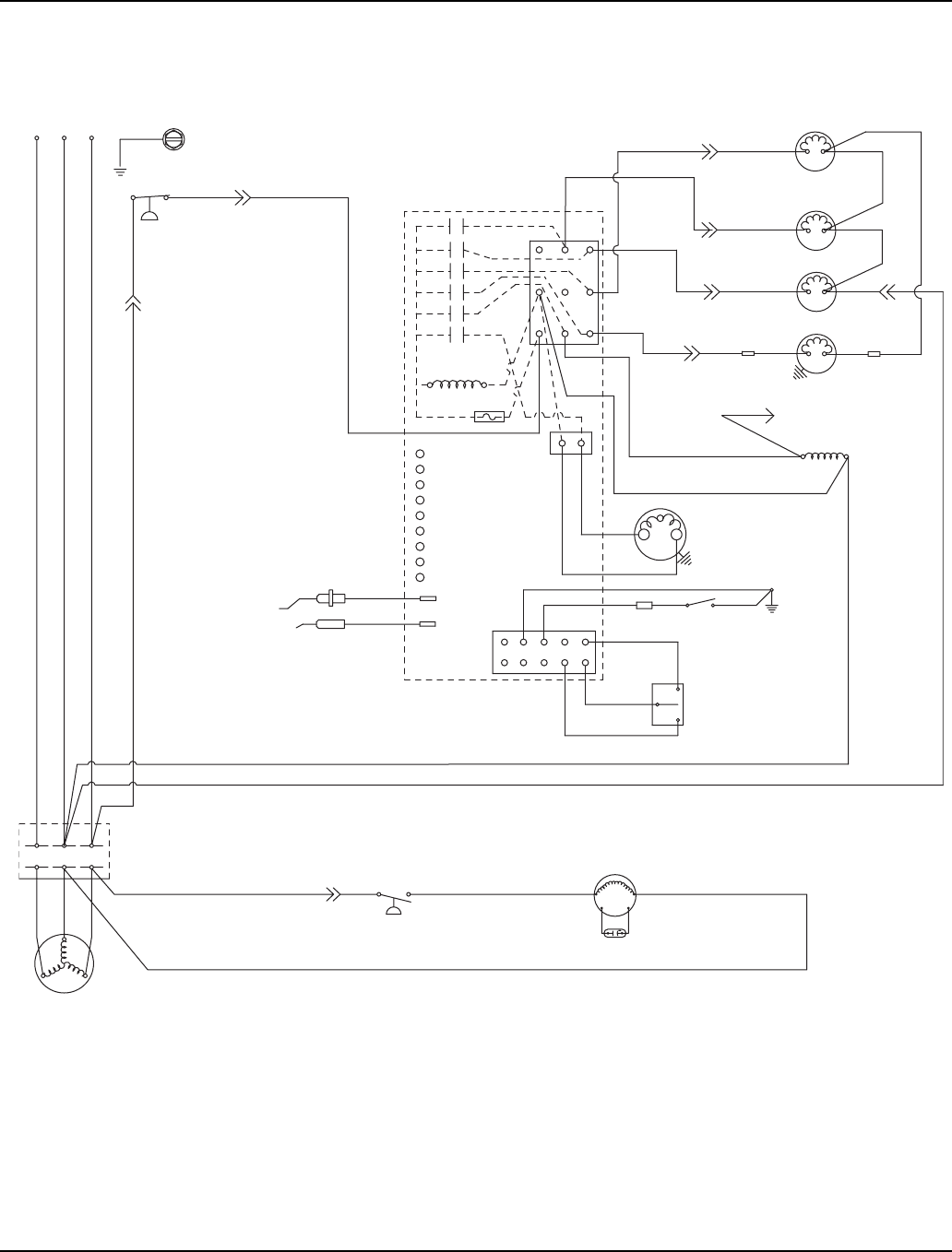
Electrical System Section 6
6-22 Part Number 80-1480-3
S850/S1000/S1200 - SELF CONTAINED - 3 PHASE
SV3131
(89) (55)
(88)
(42)
High Pressure
Cutout
Water Valve
Harvest Valve
Dump Valve
Water Pump
Terminates at
Pin Connection
(20) (21)
(22)
(74)
Ice Thickness
Probe
Water Level Probe
Control
Board
(61)
(60)
(57) (98)
(99)
(76)
(81)
(75)
(77)
(80)
(26)
(25)
(58)
(59)
Contactor
Coil
(56)
Trans.
Fuse (7a)
Low DC
Voltage
Plug
L1
(51) (85) (86)
Fan Cycle
Control
Fan Motor
Run Capacitor
Compressor
L1 Ground
(2
(6)
(5)
(1)
(7)
(4)
L2
Air Compressor
(When Used)
Bin Switch
Clean
OFF
ICE
(2)
(1)
(6)
(8)
(9)
Contactor
Contacts
(75)
L2
L3
L2L3
T2
T1
T3
(99)
Clean
Left Bin
Right Bin
Wtr Probe
Rmt Bin
Ice Probe
Harvest
SL-2
SL-1
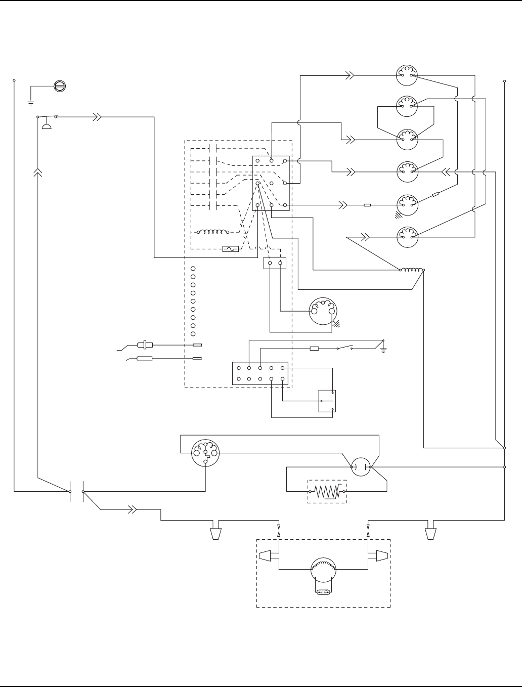
Section 6 Electrical System
Part Number 80-1480-3 6-23
S500/S600/S850/S1000 - REMOTE - 1 PHASE
SV3158
(89) (55)
(88)
(42)
High Pressure
Cutout
Water Valve
Harvest Valve
Dump Valve
Water Pump
(20) (21)
(79)
(74)
Ice Thickness
Probe
Water Level Probe
Control
Board
(61)
(60)
(57) (98) (99)
(76)
(81)
(77)
(80)
(26)
(25)
(58)
(59)
Contactor
Coil
(56)
Trans.
Fuse (7a)
Low DC
Voltage
Plug
L1
(51) (F1)
Fan Motor
Run Capacitor
PTCR
Compressor Run
Capacitor (50)
(45)
L2 or N
L1
Ground
(2)
(6)
(5)
(1)
(7)
(4)
L2
Air Compressor
(When Used)
Bin Switch
Clean
OFF
ICE
(2)
(1)
(6)
(8)
(9)
Overload
(Red)
(Yellow)
(Black)
Contactor
Contacts (46) RR
(83)
(22)
(22)
(75)
Remote Condenser
(F2)
Clean
Left Bin
Right Bin
Wtr Probe
Rmt Bin
Ice Probe
Harvest
SL-2
SL-1
Liquid Line
Solenoid
HPR Valve
(78)
(82)
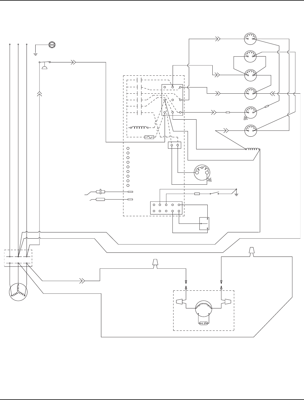
Electrical System Section 6
6-24 Part Number 80-1480-3
S850/S1000 - REMOTE - 3 PHASE
SV3159
(89) (55)
(88)
(42)
High Pressure
Cutout
Harvest Valve
Dump Valve
Water Pump
(20) (21) (22)
(74)
Ice Thickness
Probe
Water Level Probe
Control
Board
(61)
(60)
(57) (98) (99)
(76)
(81)
(75)
(77)
(80)
(26)
(25)
(58)
(59) Contactor Coil
(56)
Trans.
Fuse (7a)
Low DC
Voltage
Plug
L1
(51)
F1
Fan Motor
Run Capacitor
Compressor
L1 Ground
(2)
(6)
(5)
(1)
(7)
(4)
L2
Air Compressor
(When Used)
Bin Switch
Clean
OFF
ICE
(2) (1)
(6)
(8)
(9)
Contactor
Contacts
(75)
L2
L3
L2L3
T2
T1
T3
Liquid Solenoid
F2
(83)
(22)
(82)
(78) (79)
(82)
(74)
(75)
HPR Valve
Water Valve
Clean
Left Bin
Right Bin
Wtr Probe
Rmt Bin
Ice Probe
Harvest
SL-2
SL-1
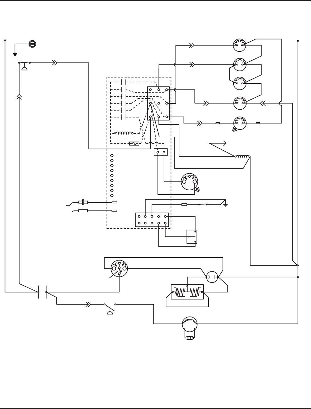
Section 6 Electrical System
Part Number 80-1480-3 6-25
S1400/S1600/S1800 - SELF-CONTAINED - 1 PHASE
(2)
(1)
R
S
CLEAN
OFF
ICE
RUN
CAPACITOR
(50)
(45)
R
(46)
PTCR
(AIR COOLED ONLY)
FAN MOTOR
RUN CAPACITOR**
(86)(85)
(51)
(BLACK)
*OVERLOAD
C
R
COMPRESSOR
(YELLOW)
(RED)
CONTACTOR
L1
CONTACTS
FAN CYCLE
CONTROL
(59)
CLEAN
LEFT BIN
RIGHT BIN
RMT BIN
WTR PROBE
ICE PROBE
HARVEST
SL-1
SL-2
(6)
(25)
(26)
L2 AIR
COMP
(9)
(8)
(42)
CONTROL BOARD
BIN
SWITCH
LOW D.C.
VOLTAGE
PLUG
CONTACTOR
COIL
(56)
TERMINATES AT
PIN CONNECTION
PUMP
WATER
(99)
(98)
(58)
FUSE (7A)
TRANS.
ICE THICKNESS
WATER LEVEL
SOLENOID
(57)
DUMP (81)
(76)
LH HARVEST
SOLENOID
(87)
(77)
WATER
VALVE
(60)
(61)
(22)
(21)
(7)
(2)
(1)
(5)
HIGH PRESSURE
CUTOUT
(55)
L2 OR N
(88)
(20)
AIR
COMPRESSOR
WHEN USED
(4)
(6) RH HARVEST
SOLENOID (80)
(88)
(74)
PROBE
PROBE
(75)
L1
(89)
(44)
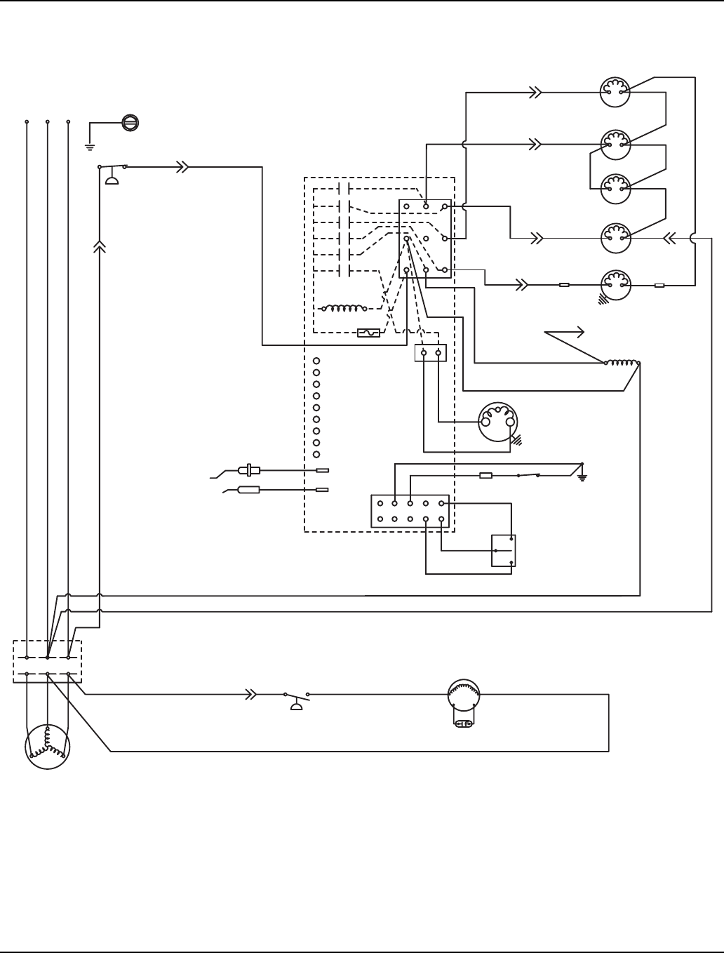
Electrical System Section 6
6-26 Part Number 80-1480-3
S1400/S1600/S1800 - SELF-CONTAINED - 3 PHASE
(42)
CONTROL BOARD
CLEAN
OFF
ICE
BIN
SWITCH
(8)
LOW D.C.
VOLTAGE
PLUG
CONTACTOR
COIL
(56)
TERMINATES AT
PIN CONNECTION
(74)
PUMP
WATER
(58)
ICE THICKNESS
PROBE
WATER LEVEL
PROBE
SOLENOID
DUMP (81)
(75)
(76)
LH HARVEST
SOLENOID
(87)
(77)
VALVE
WATER
(60)
(61)
(22)
(21)
(7)
(2)
(1)
(6)
(5)
HIGH PRESSURE
CUTOUT
(55)
(89)
(88)
(20)
(59)
CLEAN
LEFT BIN
RIGHT BIN
RMT BIN
WTR PROBE
ICE PROBE
HARV
SL-1
SL-2
AIR
COMPRESSOR
WHEN USED
(6)
(2)
(1)
(9) (25)
(26)
L2 AIR
COMP
FAN CYCLE CONTROL
T3
L2
L3
COMPRESSOR
T1
T2
(51) (85) (86)
CONTACTS
CONTACTOR
L1
L2
L3 L1
(AIR COOLED ONLY)
FAN MOTOR
RUN CAPACITOR**
FUSE (7A)
TRANS.
(4)
(99)
(98)
(57)
RH HARVEST
SOLENOID (80)
(88)
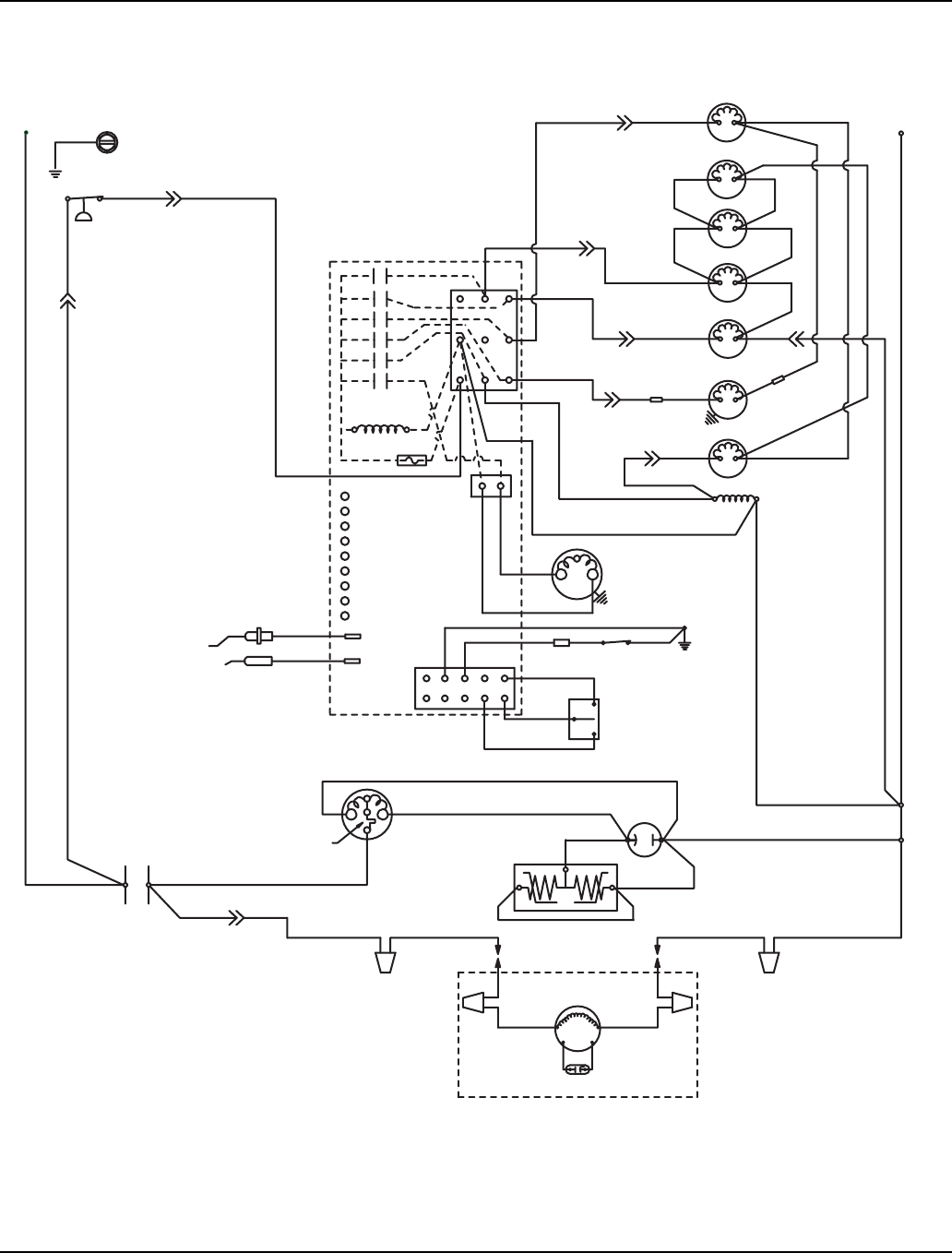
Section 6 Electrical System
Part Number 80-1480-3 6-27
S1400/S1600/S1800 - REMOTE - 1 PHASE
R
(45)
R
(46)
PTCR
(44)
(59)
CLEAN
LEFT BIN
RIGHT BIN
RMT BIN
WTR PROBE
ICE PROBE
HARV
SL-1
SL-2
(6)
(2)
(1)
(25)
(26)
L2 AIR
COMP
(9)
(8)
(42)
CONTROL BOARD
S
(79)
(51)
CLEAN
OFF
ICE
RUN
CAPACITOR
(50)
REMOTE
FAN MOTOR
RUN CAPACITOR
(F2)
(F1)
(BLACK)
*OVERLOAD
C
R
COMPRESSOR
(YELLOW)
(RED)
CONTACTOR
L1
BIN
SWITCH
LOW D.C.
VOLTAGE
PLUG
CONTACTOR
COIL
(56)
(74)
WATER
PUMP
(98)
(58)
FUSE (7A)
TRANS.
ICE THICKNESS
PROBE
WATER LEVEL
PROBE
(57)
DUMP
SOLENOID
(81)
(75)
(76)
RH HARVEST
SOLENOID
(87)
(88)
HPR
SOLENOID
(60)
(61)
(22)
(82)
(7)
(2)
(1)
(6)
(5)
HIGH PRESSURE
CUTOUT
(55)
L2 OR N
CONTACTS
(89)
(88)
(78)
AIR
COMPRESSOR
WHEN USED
(4)
LIQUID
SOLENOID
(83)
REMOTE CONDENSER
WATER
VALVE
(21)
(20)
(99)
LH HARVEST
SOLENOID (80)
(77)
L1
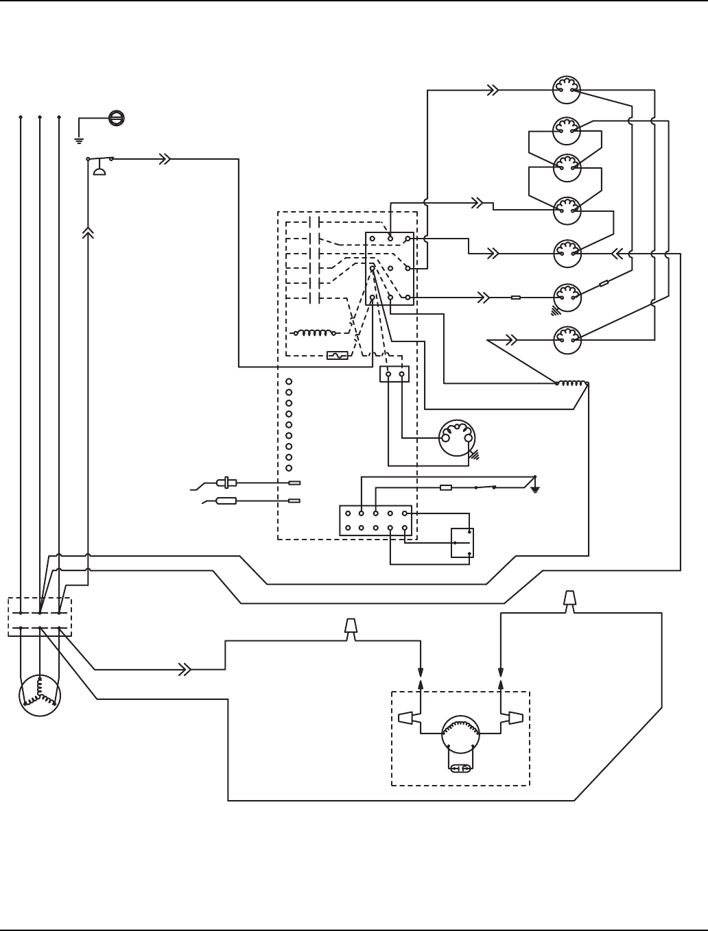
Electrical System Section 6
6-28 Part Number 80-1480-3
S1400/S1600/S1800 - REMOTE - 3 PHASE
(42)
ICE THICKNESS
PROBE
WATER LEVEL
PROBE
HIGH PRESSURE
CUTOUT
(89)
(88)
T3
L2
L3
COMPRESSOR
T1
T2
CONTACTS
CONTACTOR
L1
L2
L3 L1
CLEAN
OFF
ICE
BIN
SWITCH
LOW D.C.
VOLTAGE
PLUG
CONTACTOR
COIL
(56)
(74)
(58)
FUSE (7A)
TRANS.
SOLENOID
(57)
DUMP
(76)
RH HARVEST
SOLENOID
(88)
(60)
(61)
(7)
(2)
(1)
(6)
(5)
(55)
(59)
CLEAN
LEFT BIN
RIGHT BIN
RMT BIN
WTR PROBE
ICE PROBE
HARV
SL-1
SL-2
AIR
COMPRESSOR
WHEN USED
(6)
(2)
(1)
(25)
(26)
L2 AIR
COMP
(9)
(8)
CONTROL BOARD
(4)
(83)
(51)
(F1)
FAN MOTOR
REMOTE
(F2)
REMOTE CONDENSER
RUN CAPACITOR
PUMP
WATER
(98)
(81)
(75)
(87)
HPR
SOLENOID
(22)
(82)
(78)
LIQUID
SOLENOID
(79)
WATER
VALVE
(21)
(20)
(99)
LH HARVEST
SOLENOID
(77) (80)
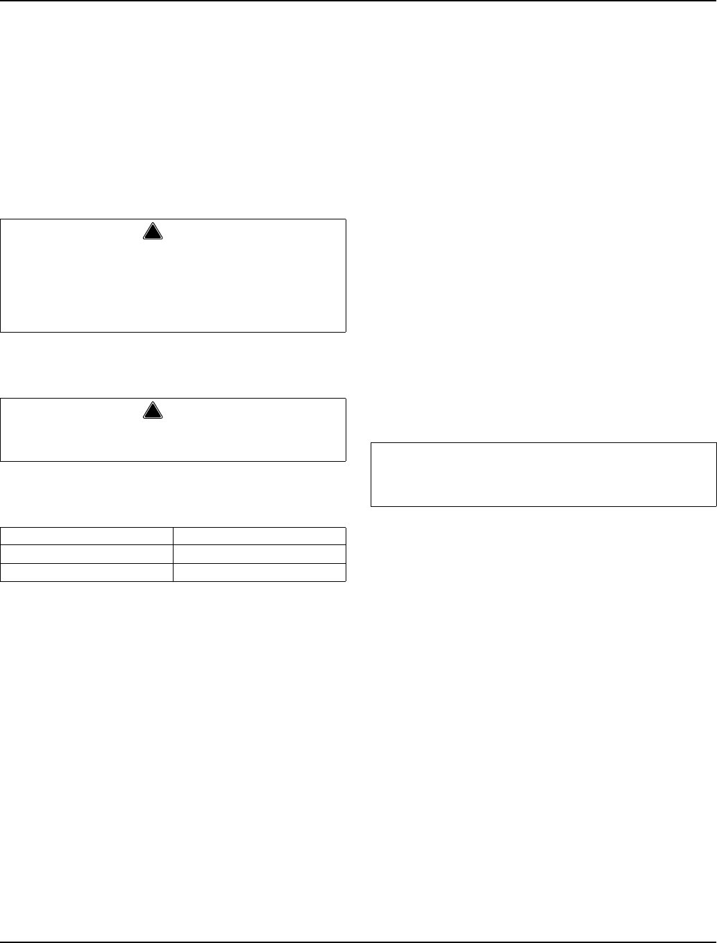
Section 6 Electrical System
Part Number 80-1480-3 6-29
Component Specifications and Diagnostics
MAIN FUSE
Function
The control board fuse stops ice machine operation if
electrical components fail causing high amp draw.
Specifications
The main fuse is 250 Volt, 7 amp.
Check Procedure
1. If the bin switch light is on with the water curtain
closed, the fuse is good.
2. Remove the fuse. Check the resistance across the
fuse with an ohm meter.
BIN SWITCH
Function
Movement of the water curtain controls bin switch
operation. The bin switch has two main functions:
1. Terminating the harvest cycle and returning the ice
machine to the freeze cycle.
This occurs when the bin switch is opened and
closed again within 30 seconds during the harvest
cycle.
2. Automatic ice machine shut-off.
If the storage bin is full at the end of a harvest cycle,
the sheet of cubes fails to clear the water curtain and
holds it open. After the water curtain is held open for
30 seconds, the ice machine shuts off. The ice
machine remains off until enough ice is removed
from the storage bin to allow the sheet of cubes to
drop clear of the water curtain. As the water curtain
swings back to the operating position, the bin switch
closes and the ice machine restarts, provide the
three-minute delay has expired.
Specifications
The bin switch is a magnetically operated reed switch.
The magnet is attached to the lower right corner of the
water curtain. The switch is attached to the right
bulkhead wall.
The bin switch is connected to a varying D.C. voltage
circuit. (Voltage does not remain constant.)
NOTE: Because of a wide variation in D.C. voltage, it is
not recommended that a voltmeter be used to check bin
switch operation.
!
Warning
High (line) voltage is applied to the control board
(terminals #55 and #56) at all times. Removing the
control board fuse or moving the toggle switch to
OFF will not remove the power supplied to the
control board.
!
Warning
Disconnect electrical power to the entire ice
machine before proceeding.
Reading Result
Open (OL) Replace fuse
Closed (O) Fuse is good
Important
The water curtain must be ON (bin switch(s) closed)
to start ice making.

Electrical System Section 6
6-30 Part Number 80-1480-3
Symptoms
Bin Switch Fails Open
• The ice machine will not start with the toggle switch
in the ice position, but runs normally with the toggle
switch in the clean position.
Bin Switch Fails Closed
• Safety limit 2 is recorded in the control board
memory and the harvest cycle continues after the ice
opens and closes the water curtain (harvest cycle is
3.5 minutes long).
Diagnostic Aids:
• Always use the water curtain magnet to cycle the
switch (a larger or smaller magnet will affect switch
operation).
• Readings are affected by your test lead connection
and VOM battery strength. Verify you have solid
connections and a correctly functioning VOM before
testing bin switch.
• Open the curtain for 3 seconds, then close the
curtain for 3 seconds. This will allow your VOM
display to settle.
• With the bin switch closed your meter reading should
be 0 (0 to 10 is acceptable). With the curtain open the
reading must be infinity (OL).
Continuity Test
1. Disconnect the bin switch wires to isolate the bin
switch from the control board.
2. Connect an ohmmeter to the disconnected bin
switch wires.
3. Cycle the bin switch open and closed 25 times by
opening and closing the water curtain. Watch for
consistent readings each time the bin switch is
cycled open and closed (bin switch failure could be
erratic).
Water Curtain Removal Notes
The water curtain must be on (bin switch closed) to start
ice making. While a freeze cycle is in progress, the water
curtain can be removed and installed at any time without
interfering with the electrical control sequence.
If the ice machine goes into harvest sequence while the
water curtain is removed, one of the following will
happen:
• Water curtain remains off:
When the harvest cycle time reaches 3.5 minutes
and the bin switch is not closed, the ice machine
stops as though the bin were full.
• Water curtain is put back on:
If the bin switch closes prior to reaching the 3.5-
minute point, the ice machine immediately returns to
another freeze sequence prechill.

Section 6 Electrical System
Part Number 80-1480-3 6-31
COMPRESSOR ELECTRICAL DIAGNOSTICS
The compressor will not start or will trip repeatedly on
overload.
Check Resistance (Ohm) Values
NOTE: Compressor windings can have very low ohm
values. Use a properly calibrated meter.
Perform the resistance test after the compressor cools.
The compressor dome should be cool enough to touch
(below 120°F/49°C) to assure that the overload is closed
and the resistance readings will be accurate.
SINGLE PHASE COMPRESSORS
1. Disconnect power from the cuber and remove the
wires from the compressor terminals.
2. The resistance values between C and S and
between C and R, when added together, should
equal the resistance value between S and R.
3. If the overload is open, there will be a resistance
reading between S and R, and open readings
between C and S and between C and R. Allow the
compressor to cool, then check the readings again.
THREE PHASE COMPRESSORS
1. Disconnect power from the cuber and remove the
wires from the compressor terminals.
2. The resistance values between L1 and L2, between
L2 and L3, and between L3 and L1 should all be
equal.
3. If the overload is open, there will be open readings
between L1 and L2, between L2 and L3, and
between L3 and L1. Allow the compressor to cool,
then check the readings again.
Check Motor Windings to Ground
Check continuity between all three terminals and the
compressor shell or copper refrigeration line. Scrape
metal surface to get good contact. If continuity is
present, the compressor windings are grounded and the
compressor should be replaced.
Determine if the Compressor is Seized
Check the amp draw while the compressor is trying to
start.
COMPRESSOR DRAWING LOCKED ROTOR
The two likely causes of this are:
• Defective starting component
• Mechanically seized compressor
To determine which you have:
1. Install high and low side gauges.
2. Try to start the compressor.
3. Watch the pressures closely.
A. If the pressures do not move, the compressor is
seized. Replace the compressor.
B. If the pressures move, the compressor is turning
slowly and is not seized. Check the capacitors
and start relay.
COMPRESSOR DRAWING HIGH AMPS
The continuous amperage draw on start-up should not
be near the maximum fuse size indicated on the serial
tag.
Diagnosing Capacitors
• If the compressor attempts to start, or hums and trips
the overload protector, check the starting
components before replacing the compressor.
• Visual evidence of capacitor failure can include a
bulged terminal end or a ruptured membrane. Do not
assume a capacitor is good if no visual evidence is
present.
• A good test is to install a known good substitute
capacitor.
• Use a capacitor tester when checking a suspect
capacitor. Clip the bleed resistor off the capacitor
terminals before testing.

Electrical System Section 6
6-32 Part Number 80-1480-3
PTCR DIAGNOSTICS
What is a PTCR?
A PTCR (or Positive Temperature Coefficient Resistor) is
made from high-purity, semi-conducting ceramics.
A PTCR is useful because of its resistance versus
temperature characteristic. The PTCR has a low
resistance over a wide (low) temperature range, but
upon reaching a certain higher temperature, its
resistance greatly increases, virtually stopping current
flow. When the source of heat is removed, the PTCR
returns to its initial base resistance.
In severe duty cycles, it can be used to repeatedly
switch (virtually stop) large currents at line voltages.
PTCR’s have been used for many years in millions of
HVAC applications. In place of using the conventional
start relay/start capacitor, a simple PTCR provides the
starting torque assistance to PSC (Permanent Split
Capacitor) single-phase compressors, which can
equalize pressures before starting.
Compressor Start Sequence
PTCR’s provide additional starting torque by increasing
the current in the auxiliary (start) winding during starting.
The PTCR is wired across the run capacitor (in series
with the start winding).
1. It is important for the refrigerant discharge and
suction pressures to be somewhat equalized prior to
the compressor starting. To assure equalization of
pressures the harvest valve (and HPR valve on
remotes) will energize for 45 seconds prior to
compressor starting. The harvest valve (and HPR
valve on remotes) remains on for an additional 5
seconds while the compressor is starting.
2. When starting the compressor, the contactor closes
and the PTCR, which is at a low resistance value,
allows high starting current to flow in the start
winding.
3. The current passing through the PTCR causes it to
rapidly heat up, and after approximately .25-1
second it abruptly “switches” to a very high
resistance, virtually stopping current flow through it.
4. At this point the motor is up to speed and all current
going through the start winding will now pass
through the run capacitor.
5. The PTCR remains hot and at a high resistance as
long as voltage remains on the circuit.
6. It is important to provide time between compressor
restarts to allow the PTCR to cool down to near its
initial temperature (low resistance). When the
contactor opens to stop the compressor, the PTCR
cools down to its initial low resistance and is again
ready to provide starting torque assistance. To
assure the PTCR has cooled down, during an
automatic shut-off, the S model ice machines have a
built-in 3-minute off time before it can restart.
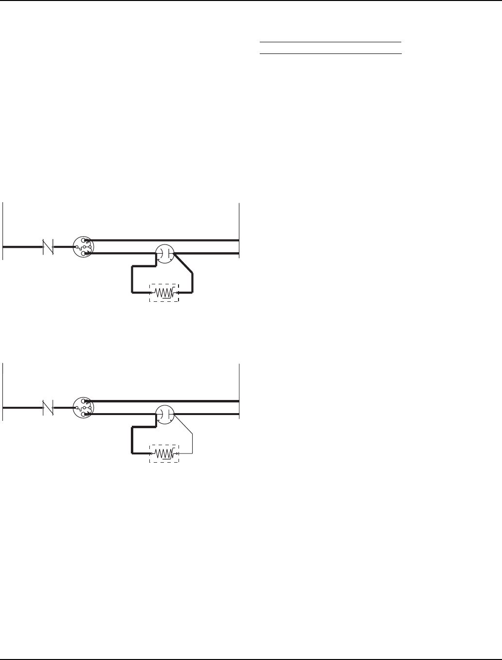
Section 6 Electrical System
Part Number 80-1480-3 6-33
S-Model Automatic Shut-Off and Restart
When the storage bin is full at the end of a harvest cycle,
the sheet of cubes fails to clear the water curtain and will
hold it open. After the water curtain is held open for 30
seconds, the ice machine shuts off. To assure the PTCR
has cooled, the ice machine remains off for 3 minutes
before it can automatically restart.
The ice machine remains off until enough ice has been
removed from the storage bin to allow the ice to fall clear
of the water curtain. As the water curtain swings back to
operating position, the bin switch closes and the ice
machine restarts, provided the three-minute delay period
is complete.
During Start-Up (First .25 - 1.0 Seconds)
After Start-Up
(Current Flows Through Run Capacitor)
Troubleshooting PTCR’s
WHY A GOOD PTCR MAY FAIL
TO START THE COMPRESSOR
The PTCR must be cooled before attempting to start the
compressor, otherwise the high starting torque may not
last long enough.
For example, if the PTCR is properly cooled, say 60°F
(15.6°C) when the compressor starts, it will take .25 to
1.0 seconds before its temperature reaches 260°F
(126.6°C), and current flow is stopped.
If the PTCR is still warm, say 160°F (71.1°C) when the
compressor starts, it will take only .125 to .50 seconds
before its temperature reaches 260°F (126.6°C), and
current flow is stopped. This decreased time may be
insufficient to start the compressor.
A good PTCR may be too hot to operate properly at
start-up because:
• The ice machine’s 3-minute delay has been
overridden. Opening and closing the service
disconnect or cycling the toggle switch from OFF to
ICE will override the delay period.
• The control box temperature is too high. Though
rare, very high air temperatures (intense sunlight,
etc.) can greatly increase the temperature of the
control box and its contents. This may require a
longer off time to allow the PTCR to cool.
• The compressor has short-cycled, or the compressor
overload has opened. Move the toggle switch to OFF
and allow the compressor and PTCR to cool.
Continued on next page …
SV1506
L1 L2
CONTACTOR
CONTACTS RUN CAPACITOR
RR
PTCR
COMPRESSOR
C
S
R
SV1507
L1 L2
CONTACTOR
CONTACTS RUN CAPACITOR
RR
PTCR
COMPRESSOR
C
S
R
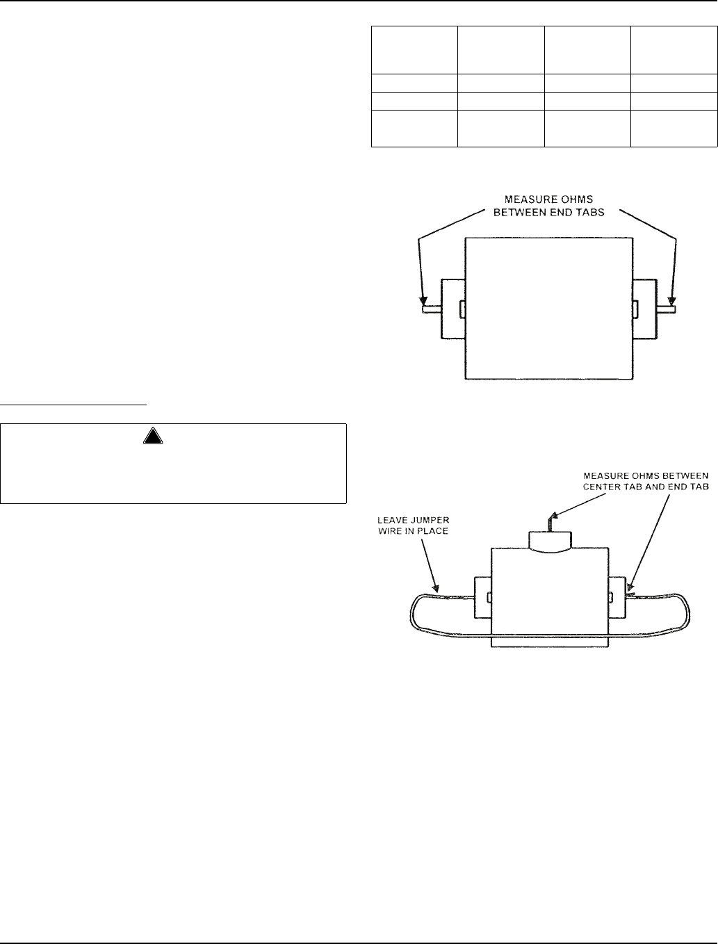
Electrical System Section 6
6-34 Part Number 80-1480-3
There are other problems that may cause compressor
start-up failure with a good PTCR in a new, properly
wired ice machine.
• The voltage at the compressor during start-up is too
low.
Manitowoc ice machines are rated at ±10% of
nameplate voltage at compressor start-up. (Ex: An
ice machine rated at 208-230 should have a
compressor start-up voltage between 187 and 253
volts.)
• The compressor discharge and suction pressures
are not matched closely enough or equalized.
These two pressures must be somewhat equalized
before attempting to start the compressor. The
harvest valve (and HPR valve on remotes) energizes
for 45 seconds before the compressor starts, and
remains on 5 seconds after the compressor starts.
Make sure this is occurring and the harvest valve
(and HPR solenoid) coil is functional before
assuming that the PTCR is bad.
CHECKING THE PTCR
1. Visually inspect the PTCR. Check for signs of
physical damage.
NOTE: The PTCR case temperature may reach 210°F
(100°C) while the compressor is running. This is normal.
Do not change a PTCR just because it is hot.
2. Wait at least 10 minutes for the PTCR to cool to
room temperature.
3. Remove the PTCR from the ice machine.
4. Measure the resistance of the PTCR as shown
below. If the resistance falls outside of the
acceptable range, replace it.
Manitowoc PTCR’s 8505003 & 8504993
Manitowoc PTCR 8504913
!
Warning
Disconnect electrical power to the entire ice
machine at the building electrical disconnect box
before proceeding.
Model Manitowoc
Part Number Cera-Mite
Part Number
Room
Temperature
Resistance
S500/S600 8505003 305C20 22-50 Ohms
S850/S1000 8504993 305C19 18-40 Ohms
S1200/S1400
S1600/S1800 8504913 305C9 8-22 Ohms
SV1540
SV1541

Section 6 Electrical System
Part Number 80-1480-3 6-35
DIAGNOSING START COMPONENTS
If the compressor attempts to start, or hums and trips the
overload protector, check the start components before
replacing the compressor.
Capacitor
Visual evidence of capacitor failure can include a bulged
terminal end or a ruptured membrane. Do not assume a
capacitor is good if no visual evidence is present. A good
test is to install a known good substitute capacitor. Use a
capacitor tester when checking a suspect capacitor. Clip
the bleed resistor off the capacitor terminals before
testing.
Relay
The relay has a set of contacts that connect and
disconnect the start capacitor from the compressor start
winding. The contacts on the relay are normally closed
(start capacitor in series with the start winding). The
relay senses the voltage generated by the start winding
and opens the contacts as the compressor motor starts.
The contacts remain open until the compressor is de-
energized.
Relay Operation Check
1. Disconnect wires from relay terminals.
2. Verify the contacts are closed.
Measure the resistance between terminals 1 and 2.
No continuity indicates open contacts. Replace the
relay.
3. Check the relay coil.
Measure the resistance between terminals 2 and 5.
No resistance indicates an open coil. Replace the
relay.
HARVEST ASSIST AIR COMPRESSOR
Function
The air compressor breaks the vacuum between the
sheet of ice and the evaporator which results in shorter
harvest cycles.
Specifications
115 Volt or 230 Volt - matches the ice machine voltage.
Check Procedure
1. Verify when the air compressor should be running in
the sequence of operation.
2. If the compressor is not running when it should be
check voltage at the control board.
3. If there is no voltage present at the control board,
replace the control board.
4. If there is voltage present at the control board check
for voltage at the air compressor connector.
5. If there is no voltage present at the air compressor
connector replace wire.
6. If there is voltage at the air compressor connector,
use a volt ohm meter to verify there is no continuity
through the motor windings then replace motor.
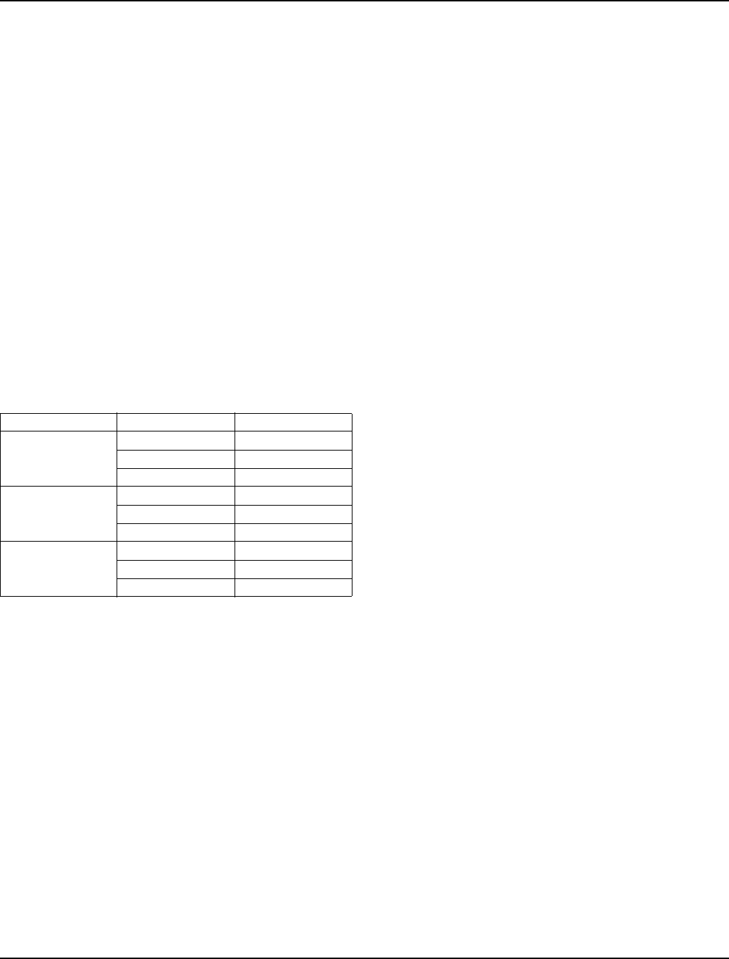
Electrical System Section 6
6-36 Part Number 80-1480-3
ICE/OFF/CLEAN TOGGLE SWITCH
Function
The switch is used to place the ice machine in ICE, OFF
or CLEAN mode of operation.
Specifications
Single-pole, single-throw switch. The switch is
connected into a varying low D.C. voltage circuit.
Check Procedure
NOTE: Because of a wide variation in D.C. voltage, it is
not recommended that a volt meter be used to check
toggle switch operation.
1. Inspect the toggle switch for correct wiring.
2. Isolate the toggle switch by disconnecting the Molex
connector.
3. Check continuity across the toggle switch terminals.
Note where the wire numbers are connected to the
switch terminals, or refer to the wiring diagram to
take proper readings.
4. Replace the toggle switch if ohm readings do not
match all three switch settings.
Switch Setting Terminals Ohm Reading
ICE
1-6 Open
1-2 Closed
2-6 Open
CLEAN
1-6 Closed
1-2 Open
2-6 Open
OFF
1-6 Open
1-2 Open
2-6 Open
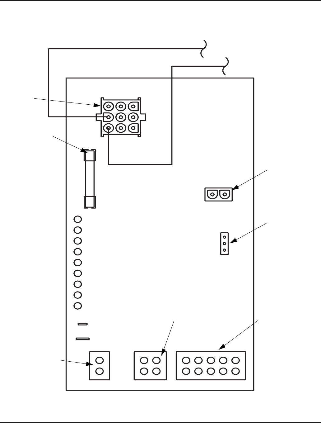
Section 6 Electrical System
Part Number 80-1480-3 6-37
ELECTRONIC CONTROL BOARD
Control Board
SV3129
AC LINE VOLTAGE
ELECTRICAL
PLUG (NUMBERS
MARKED ON
WIRES)
MAIN FUSE (7A)
AUTOMATIC CLEANING
SYSTEM (AuCS) PLUG
ICE THICKNESS
PROBE (3/16''
CONNECTION)
WATER LEVEL PROBE
DC LOW VOLTAGE
ELECTRICAL PLUG
(NUMBERS MARKED ON
WIRES)
WATER PROBE LIGHT (GREEN)
LEFT BIN LIGHT (GREEN)
HARVEST LIGHT (RED)
REMOTE BIN
CLEAN LIGHT (YELLOW) WATER PURGE
ADJUSTMENT
AIR COMPRESSOR
(NOT USED ON
ALL MODELS)
RIGHT BIN LIGHT (GREEN)
PRIMARY POWER SUPPLY
N 115V
L2 208-230V
REMOTE BIN LIGHT (GREEN)
ICE PROBE LIGHT (GREEN)
SAFETY LIMIT 1 LIGHT (RED)
SAFETY LIMIT 2 LIGHT (RED)

Electrical System Section 6
6-38 Part Number 80-1480-3
General
S-Model control boards use a dual voltage transformer.
This means only one control board is needed for both
115V and 208-230V use.
Safety Limits
In addition to standard safety controls, such as the high
pressure cut-out, the control board has built-in safety
limits.
These safety limits protect the ice machine from major
component failures. For more information, see “Safety
Limits” in Section 7.
Inputs
The control board, along with inputs, controls all
electrical components, including the ice machine
sequence of operation. Prior to diagnosing, you must
understand how the inputs affect the control board
operation.
Refer to specific component specifications (inputs),
wiring diagrams and ice machine sequence of operation
sections for details.
As an example, refer to “Ice Thickness Probe” on the
next page for information relating to how the probe and
control board function together.
This section will include items such as:
• How a harvest cycle is initiated
• How the harvest light functions with the probe
• Freeze time lock-in feature
• Maximum freeze time
• Diagnosing ice thickness control circuitry
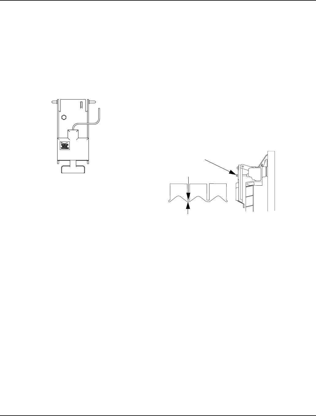
Section 6 Electrical System
Part Number 80-1480-3 6-39
Ice Thickness Probe (Harvest Initiation)
HOW THE PROBE WORKS
Manitowoc’s electronic sensing circuit does not rely on
refrigerant pressure, evaporator temperature, water
levels or timers to produce consistent ice formation.
As ice forms on the evaporator, water (not ice) contacts
the ice thickness probe. After the water completes this
circuit across the probe continuously for 6-10 seconds, a
harvest cycle is initiated.
Ice Thickness Probe
ICE PROBE LIGHT
This light’s primary function is to be on as water contacts
the ice thickness probe during the freeze cycle, and
remain on throughout the entire harvest cycle. The light
will flicker as water splashes on the probe.
FREEZE TIME LOCK-IN FEATURE
The ice machine control system incorporates a freeze
time lock-in feature. This prevents the ice machine from
short cycling in and out of harvest.
The control board locks the ice machine in the freeze
cycle for six minutes. If water contacts the ice thickness
probe during these six minutes, the harvest light will
come on (to indicate that water is in contact with the
probe), but the ice machine will stay in the freeze cycle.
After the six minutes are up, a harvest cycle is initiated.
This is important to remember when performing
diagnostic procedures on the ice thickness control
circuitry.
To allow the service technician to initiate a harvest cycle
without delay, this feature is not used on the first cycle
after moving the toggle switch OFF and back to ICE.
MAXIMUM FREEZE TIME
The control system includes a built-in safety which will
automatically cycle the ice machine into harvest after 60
minutes in the freeze cycle.
ICE THICKNESS CHECK
The ice thickness probe is factory-set to maintain the ice
bridge thickness at 1/8" (.32 cm).
NOTE: Make sure the water curtain is in place when
performing this check. It prevents water from splashing
out of the water trough.
1. Inspect the bridge connecting the cubes. It should
be about 1/8" (.32 cm) thick.
2. If adjustment is necessary, turn the ice thickness
probe adjustment screw clockwise to increase
bridge thickness, or counterclockwise to decrease
bridge thickness. Set a 1/4” gap between the ice
thickness probe and evaporator as a starting point.
Then adjust to achieve a 1/8” bridge thickness.
NOTE: The starting point before final adjustment is
approximately a 3/16 inch gap.
Ice Thickness Check
Make sure the ice thickness probe wire and the bracket
do not restrict movement of the probe.
Ice Thickness Probe Cleaning
1. Mix a solution of Manitowoc ice machine cleaner
and water (2 ounces of cleaner to 16 ounces of
water) in a container.
2. Soak ice thickness probe in container of cleaner/
water solution while disassembling and cleaning
water circuit components (soak ice thickness probe
for 10 minutes or longer).
3. Clean all ice thickness probe surfaces including all
plastic parts (do not use abrasives). Verify the ice
thickness probe cavity is clean. Thoroughly rinse ice
thickness probe (including cavity) with clean water,
then dry completely. Incomplete rinsing and
drying of the ice thickness probe can cause
premature harvest.
4. Reinstall ice thickness probe, then sanitize all ice
machine and bin/dispenser interior surfaces.
SV3135
SV3132
ADJUSTING SCREW
1/8” ICE BRIDGE THICKNESS
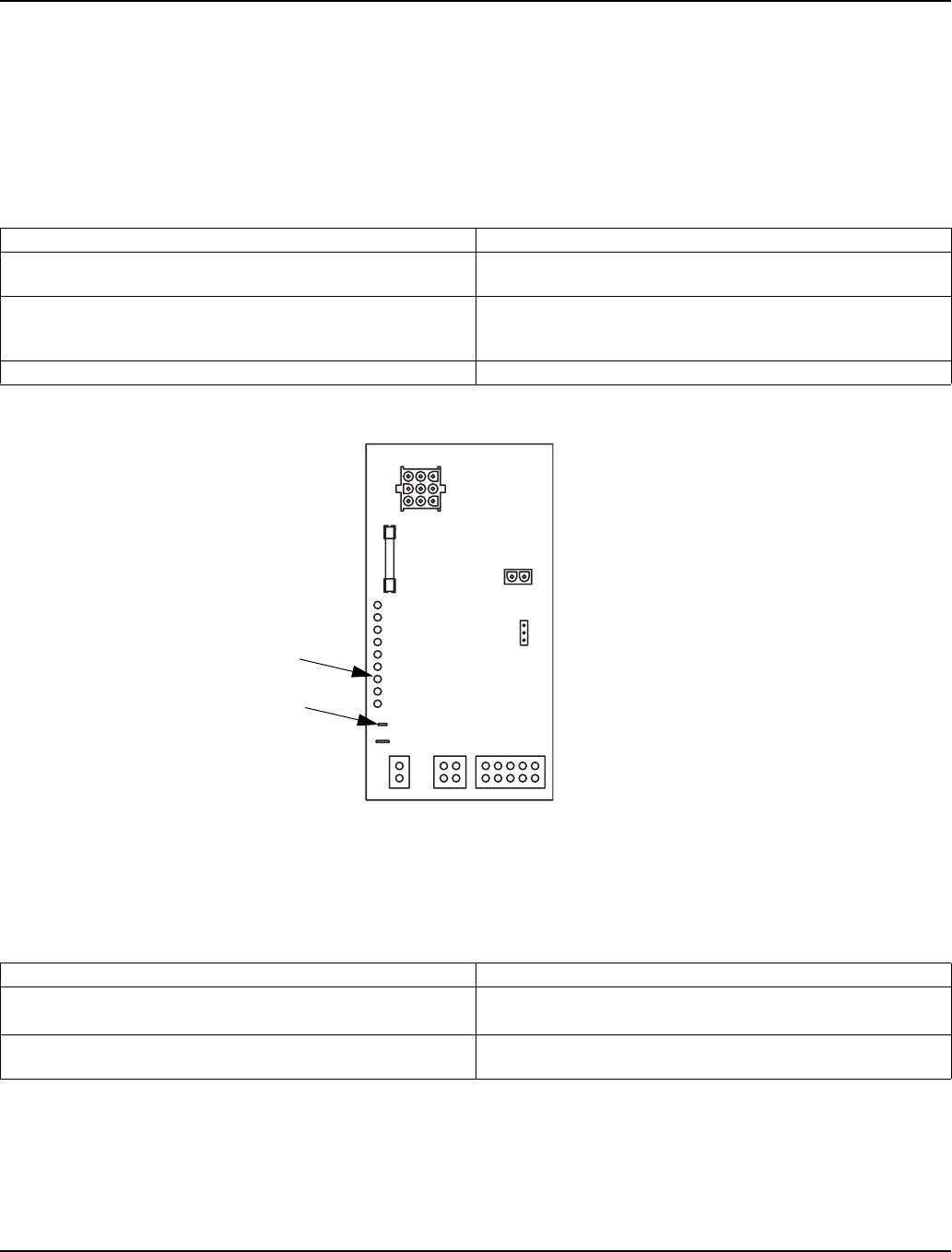
Electrical System Section 6
6-40 Part Number 80-1480-3
DIAGNOSING ICE THICKNESS CONTROL CIRCUITRY
Ice Machine Does Not Cycle Into Harvest When Water Contacts The Ice Thickness Control Probe
Step 1 Bypass the freeze time lock-in feature by moving the ICE/OFF/CLEAN switch to OFF and back to ICE.
Step 2 Wait until the water starts to flow over the evaporator (freeze cycle).
Step 3 Disconnect the ice thickness control from the control board, then connect a jumper wire from the control
board to any cabinet ground and monitor the harvest light.
Ice Machine Cycles Into Harvest Before Water Contact With The Ice Thickness Probe
Step 1 Disconnect the ice thickness probe from the control board.
Step 2 Wait until water starts to flow over the evaporator, then monitor the harvest light:
Monitoring of Harvest Light Correction
The harvest light comes on, and 10 seconds later, ice machine
cycles from freeze to harvest. The ice thickness probe is causing the malfunction.
The harvest light comes on but the ice machine stays in the
freeze sequence. The control circuitry is functioning properly. The ice machine is
in a six-minute freeze time lock-in (verify step 1 of this
procedure was followed correctly).
The harvest light does not come on. The control board is causing the malfunction.
Monitoring of Harvest Light Correction
The harvest light stays off and the ice machine remains in the
freeze sequence. The ice thickness probe is causing the malfunction.
Verify that the Ice Thickness probe is adjusted correctly.
The harvest light comes on, and 10 seconds later, the ice
machine cycles from freeze to harvest. The control board is causing the malfunction.
ICE THICKNESS
PROBE CONNECTION
HARVEST LIGHT
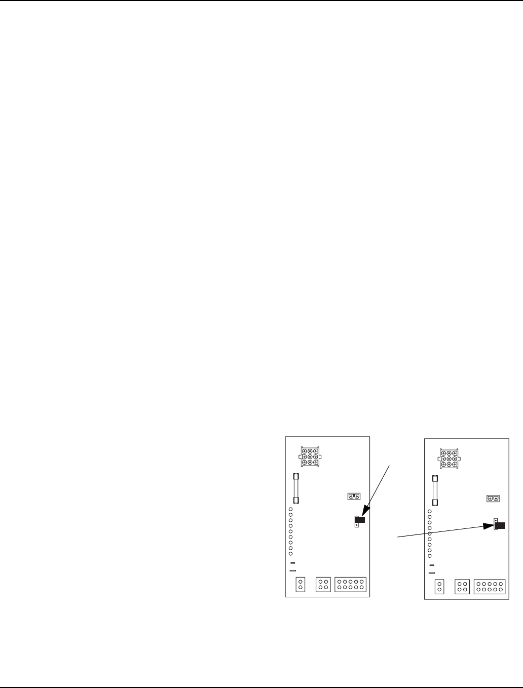
Section 6 Electrical System
Part Number 80-1480-3 6-41
Water Level Control Circuitry
WATER LEVEL PROBE LIGHT
The water level probe circuit can be monitored by
watching the water level light. The water level light is on
when water contacts the probe, and off when no water is
in contact with the probe. The water level light functions
any time power is applied to the ice machine, regardless
of toggle switch position.
During the freeze cycle, the water level probe is set to
maintain the proper water level above the water pump
housing. The water level is not adjustable. If the water
level is incorrect, check the water level probe position.
Reposition or replace the probe as necessary.
WATER INLET VALVE SAFETY SHUT-OFF
In the event of a water level probe failure, this feature
limits the water inlet valve to a 6-minute on time.
Regardless of the water level probe input, the control
board automatically shuts off the water inlet valve if it
remains on for 6 continuous minutes.
FREEZE CYCLE CIRCUITRY
Manitowoc’s electronic sensing circuit does not rely on
float switches or timers to maintain consistent water
level control. During the freeze cycle, the water inlet
valve energizes (turns on) and de-energizes (turns off) in
conjunction with the water level probe located in the
water trough.
During the first 45 seconds of the Freeze Cycle:
• The water inlet valve is on when there is no water in
contact with the water level probe.
• The water inlet valve turns off after water contacts
the water level probe for 3 continuous seconds.
• The water inlet valve will cycle on and off as many
times as needed to fill the water trough.
After 45 seconds into the Freeze Cycle:
The water inlet valve will cycle on, and then off one more
time to refill the water trough. The water inlet valve is
now off for the duration of the freeze sequence.
HARVEST CYCLE CIRCUITRY
The water level probe does not control the water inlet
valve during the harvest cycle. During the harvest cycle
water purge, the water inlet valve energizes and de-
energizes strictly by time. The harvest water purge
jumper may be set at 45 seconds (top and center
terminals) or 0 seconds (center and bottom terminals).
Set the harvest water purge to 0 seconds when reverse
osmosis or deionized water is used. Use the factory
setting of 45 seconds for all other types of water.
45 SECOND
JUMPER
POSITION
0 SECOND
JUMPER
POSITION
HARVEST WATER PURGE ADJUSTMENT
SV3139
SV3140
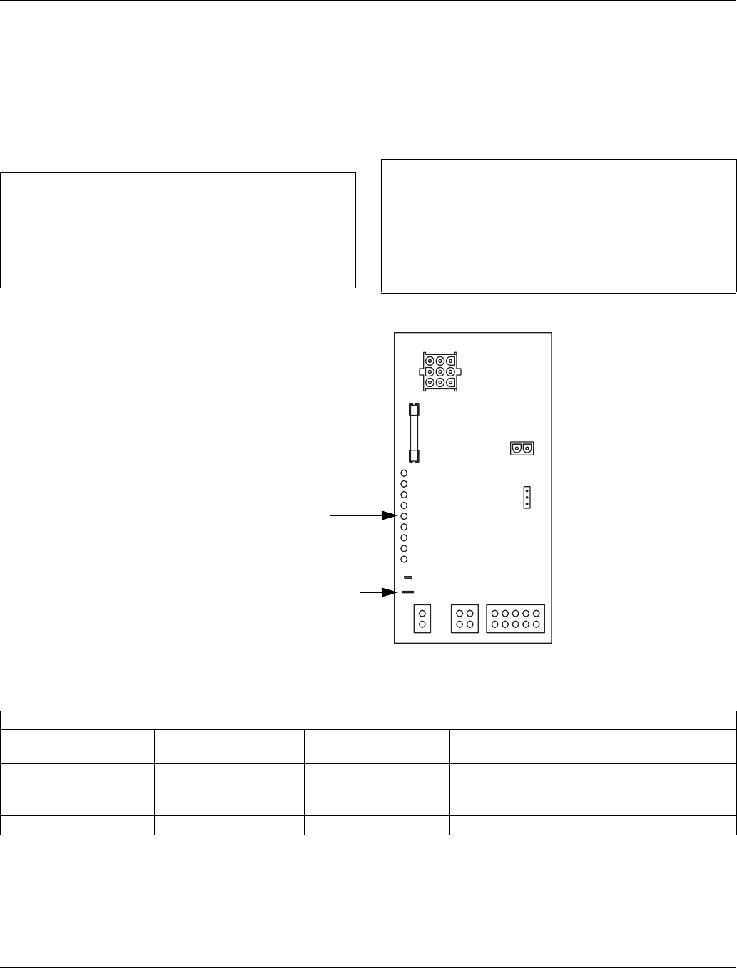
Electrical System Section 6
6-42 Part Number 80-1480-3
DIAGNOSING WATER LEVEL CONTROL CIRCUITRY
Problem: Water Trough Overfilling During The
Freeze Cycle
Step 1 Start a new freeze sequence by moving the ICE/
OFF/CLEAN toggle switch to OFF, then back to ICE. (if
water flows with the switch off, check the water inlet
valve).
Step 2 Wait until the freeze cycle starts
(the freeze cycle starts when the water pump energizes).
Step 3 Disconnect water level probe wire from control
board and connect a jumper from the control board
terminal and any cabinet ground, then refer to chart.
Step 3
Important
This restart must be done prior to performing
diagnostic procedures. This assures the ice
machine is not in a freeze cycle water inlet valve
safety shut off mode. You must complete the entire
diagnostic procedure within 6 minutes of starting.
Important
For the test to work properly you must wait until the
freeze cycle starts, prior to connecting the jumper
wire. If you restart the test you must disconnect the
jumper wire, restart the ice machine, (step 1) and
then reinstall the jumper wire after the compressor
starts.
SV3135
GREEN WATER LEVEL LIGHT
WATER LEVEL PROBE CONNECTION
Step 3 Jumper wire connected from control board terminal to ground
Is water flowing into
the water trough? The Water Level
Light is: The Water Inlet Valve
Solenoid Coil is: Cause
NO ON De-Energized The water level probe is causing the problem.
Clean or replace the water level probe.
YES ON Energized The control board is causing the problem.
YES OFF De-Energized The water fill valve is causing the problem.
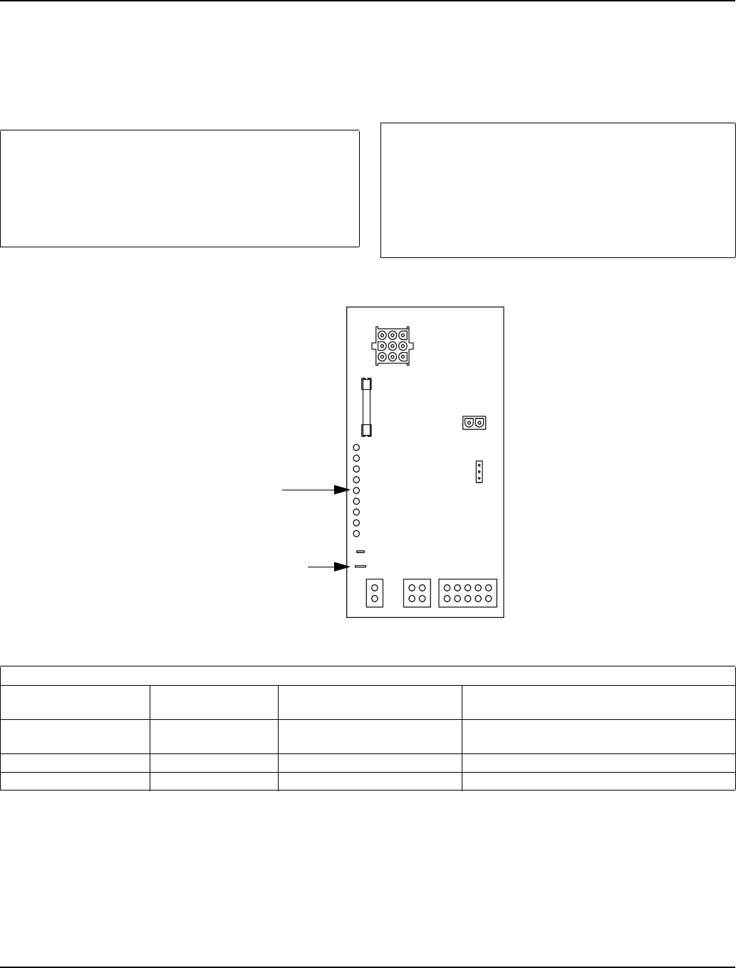
Section 6 Electrical System
Part Number 80-1480-3 6-43
Problem: Water Will Not Run Into The Sump Trough
During The Freeze Cycle
Step 1 Verify water is supplied to the ice machine, and
then start a new freeze sequence by moving the ICE/
OFF/CLEAN toggle switch to OFF then back to ICE.
Step 2 Wait until the freeze cycle starts (approximately
45 seconds, the freeze cycle starts when the
compressor energizes).
Step 3 Disconnect the water level probe from the water
level probe terminal on the control board.
Step 3
Important
This restart must be done prior to performing
diagnostic procedures. This assures the ice machine
is not in a freeze cycle water inlet valve safety shut-
off mode. You must complete the entire diagnostic
procedure within 6 minutes of starting.
Important
For the test to work properly you must wait until the
freeze cycle starts, prior to disconnecting the water
level probe. If you restart the test you must
reconnect the water level probe, restart the ice
machine, (step 1) and then disconnect the water
level probe after the compressor starts.
Step 3 Disconnect water level probe from control board terminal
Is water flowing into
the water trough? The Water Level
Light is: The Water Inlet Valve
Solenoid Coil is: Cause
YES OFF Energized The water level probe is causing the problem.
Clean or replace the water level probe.
NO OFF Energized The water inlet valve is causing the problem.
NO ON OR OFF De-Energized The control board is causing the problem.
SV3135
DISCONNECT WATER
LEVEL PROBE FROM
CONTROL BOARD
TERMINAL
GREEN WATER LEVEL LIGHT
Electrical System Section 6
6-44 Part Number 80-1480-3
Diagnosing An Ice Machine That Will Not Run
!
Warning
High (line) voltage is applied to the control board
(terminals #55 and #56) at all times. Removing
control board fuse or moving the toggle switch to
OFF will not remove the power supplied to the
control board.
Step Check Notes
1Verify primary voltage supply to ice
machine. Verify that the fuse or circuit breaker is closed.
2Verify the high-pressure cutout is closed. The H.P.C.O. is closed if primary power voltage is present at terminals
#55 and #56 on the control board.
3Verify control board fuse is OK. If the bin switch light functions, the fuse is OK.
4Verify the bin switch functions properly. A defective bin switch can falsely indicate a full bin of ice.
5Verify ICE/OFF/CLEAN toggle switch
functions properly. A defective toggle switch may keep the ice machine in the OFF mode.
6Verify low DC voltage is properly
grounded. Loose DC wire connections may intermittently stop the ice machine.
7Replace the control board. Be sure Steps 1-6 were followed thoroughly. Intermittent problems are
not usually related to the control board.
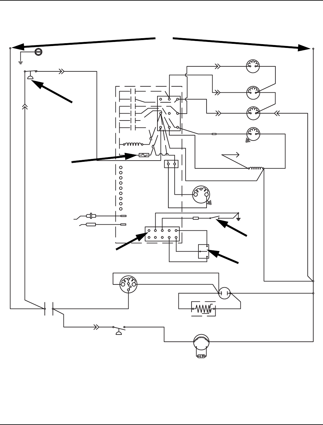
Section 6 Electrical System
Part Number 80-1480-3 6-45
S1000 - SELF CONTAINED -
1 PHASE WITH TERMINAL BOARD
SV2071
2
1
3
4
5
6

Electrical System Section 6
6-46 Part Number 80-1480-3
THIS PAGE INTENTIONALLY LEFT BLANK
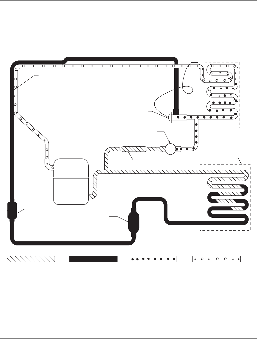
Section 7 Refrigeration System
Part Number 80-1480-3 7-1
Section 7
Refrigeration System
Sequence of Operation
SELF-CONTAINED AIR OR WATER -COOLED MODELS
Figure 7-1. Self-Contained Prechill and Freeze Cycle
Prechill Refrigeration Sequence
No water flows over the evaporator during the prechill.
The refrigerant absorbs heat (picked up during the
harvest cycle) from the evaporator. The suction pressure
decreases during the prechill.
Freeze Cycle Refrigeration Sequence
The refrigerant absorbs heat from water running over the
evaporator surface. The suction pressure gradually
drops as ice forms.
HEAT
EXCHANGER
EVAPORATOR
CONDENSER
COMPRESSOR
EXPANSION VALVE
HOT GAS SOLENOID VALVE
AIR OR WATER
DRIER
STRAINER
RECEIVER
(WATER COOLED ONLY)
LOW PRESSURE VAPORLOW PRESSURE LIQUIDHIGH PRESSURE LIQUIDHIGH PRESSURE VAPOR
X
SV1569
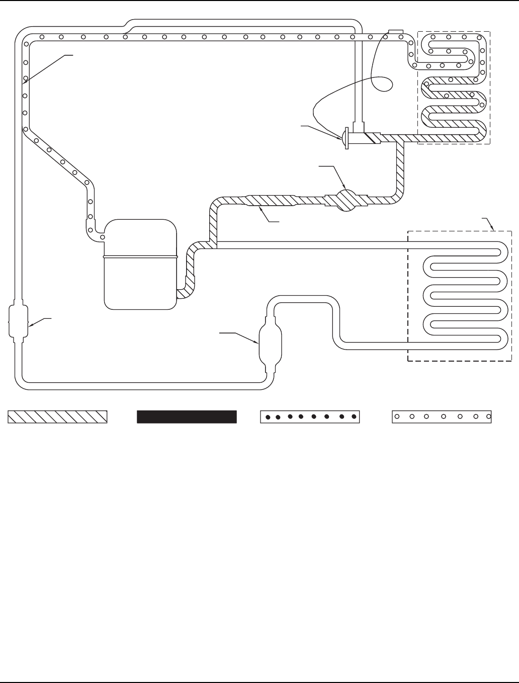
Refrigeration System Section 7
7-2 Part Number 80-1480-3
Figure 7-2. Self-Contained Harvest Cycle
Harvest Cycle Refrigeration Sequence
Hot gas flows through the energized harvest valve,
heating the evaporator. The harvest valve is sized to
allow the proper amount of refrigerant into the
evaporator. This specific sizing (along with the proper
system refrigerant charge) assures proper heat transfer,
without the refrigerant condensing and slugging the
compressor.
HEAT
EXCHANGER
EVAPORATOR
CONDENSER
COMPRESSOR
EXPANSION VALVE
HOT GAS SOLENOID VALVE
AIR OR WATER
DRIER
STRAINER
RECEIVER
(WATER COOLED ONLY)
LOW PRESSURE VAPORLOW PRESSURE LIQUIDHIGH PRESSURE LIQUIDHIGH PRESSURE VAPOR
SV1570
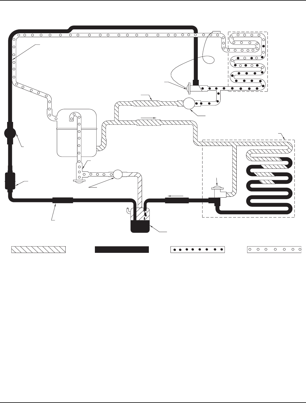
Section 7 Refrigeration System
Part Number 80-1480-3 7-3
REMOTE MODELS
Figure 7-3. Remote Pre-Chill and Freeze Cycle
Prechill Refrigeration Sequence
No water flows over the evaporator during the prechill.
The refrigerant absorbs heat (picked up during the
harvest cycle) from the evaporators. The suction
pressure decreases during the prechill.
Freeze Cycle Refrigeration Sequence
The refrigerant absorbs heat from the water running over
the evaporator surface. The suction pressure gradually
drops as ice forms.
The headmaster control valve maintains discharge
pressure in ambient temperatures below 70°F (21.1°C).
(See “Headmaster Control Valve”.)
X
X
HEAT
EXCHANGER
EVAPORATOR
SOLENOID
LINE
LIQUID
CHECK VALVE
SERVICE
RECEIVER
CONDENSER
REMOTE
COMPRESSOR
RECEIVER
EXPANSION VALVE
HOT GAS SOLENOID VALVE
VALVE
HARVEST PRESSURE
REGULATING VALVE
H.P.R. SOLENOID
VALVE
VALVE
CHECK VALVE
DRIER
STRAINER
HEAD
PRESSURE
CONTROL
VALVE
B
R
C
HIGH PRESSURE VAPOR HIGH PRESSURE LIQUID LOW PRESSURE LIQUID LOW PRESSURE VAPOR
SV1566
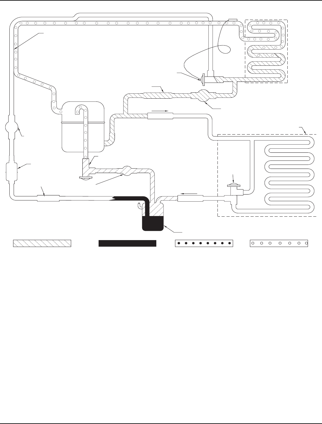
Refrigeration System Section 7
7-4 Part Number 80-1480-3
Figure 7-4. Remote Harvest Cycle
Harvest Cycle Refrigeration Sequence
Hot gas flows through the energized harvest valve,
heating the evaporator. The harvest valve is sized to
allow the proper amount of hot gas into the evaporator.
This specific harvest valve sizing, along with the harvest
pressure regulating (H.P.R.) system, assures proper
heat transfer, without the hot gas condensing to liquid
and slugging the compressor.
The harvest pressure regulating (H.P.R.) valve helps
maintain the suction pressure during the harvest cycle.
(See “H.P.R. System”.)
HEAT
EXCHANGER
EVAPORATOR
SOLENOID
LINE
LIQUID
CHECK VALVE
SERVICE
RECEIVER
CONDENSER
REMOTE
COMPRESSOR
RECEIVER
EXPANSION VALVE
HOT GAS SOLENOID VALVE
VALVE
HARVEST PRESSURE
REGULATING VALVE
H.P.R. SOLENOID
VALVE
VALVE
CHECK VALVE
DRIER
STRAINER
HEAD
PRESSURE
CONTROL
VALVE
B
R
C
HIGH PRESSURE VAPOR HIGH PRESSURE LIQUID LOW PRESSURE LIQUID LOW PRESSURE VAPOR
SV1567
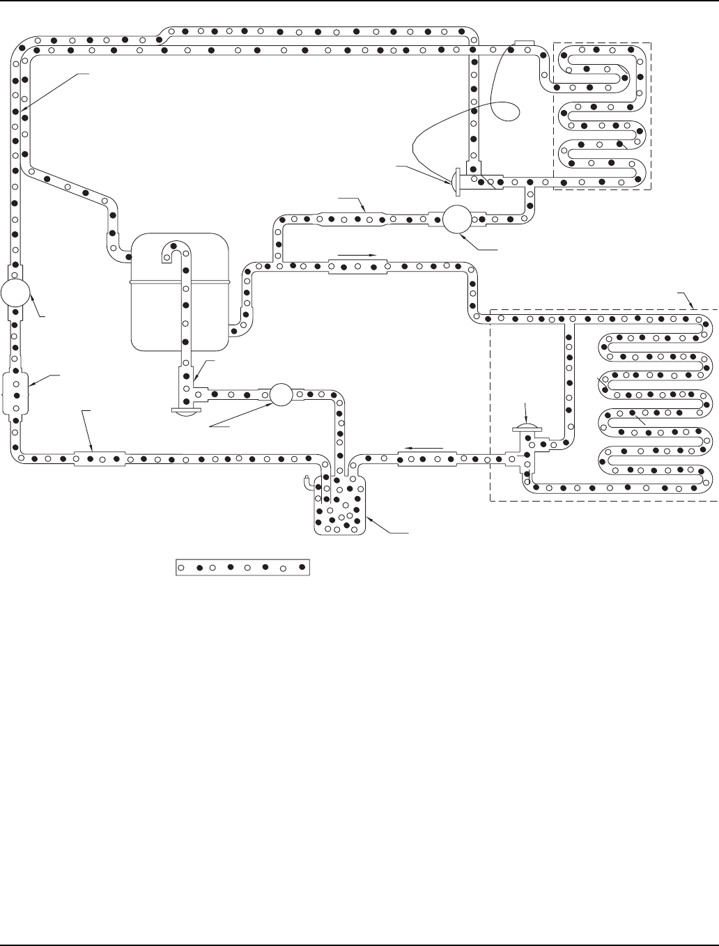
Section 7 Refrigeration System
Part Number 80-1480-3 7-5
Figure 7-5. Remote Automatic Shut-Off
Automatic Shut-Off
The compressor and liquid line solenoid valve are de-
energized simultaneously when the contactor contacts
open.
During the off cycle, the check valve prevents refrigerant
from migrating back into the high side, and the liquid line
solenoid prevents refrigerant from migrating back into
the low side. This protects the compressor from
refrigerant migration during the off cycle, preventing
refrigerant slugging upon start-up.
X
X
X
HEAT
EXCHANGER
EVAPORATOR
SOLENOID
LINE
LIQUID
CHECK VALVE
SERVICE
RECEIVER
CONDENSER
REMOTE
COMPRESSOR
RECEIVER
EXPANSION VALVE
HOT GAS SOLENOID VALVE
VALVE
HARVEST PRESSURE
REGULATING VALVE
H.P.R. SOLENOID
VALVE
VALVE
CHECK VALVE
DRIER
STRAINER
HEAD
PRESSURE
CONTROL
VALVE
B
R
C
LIQUID/VAPOR EQUALIZED TO AMBIENT CONDITIONS
SV1568
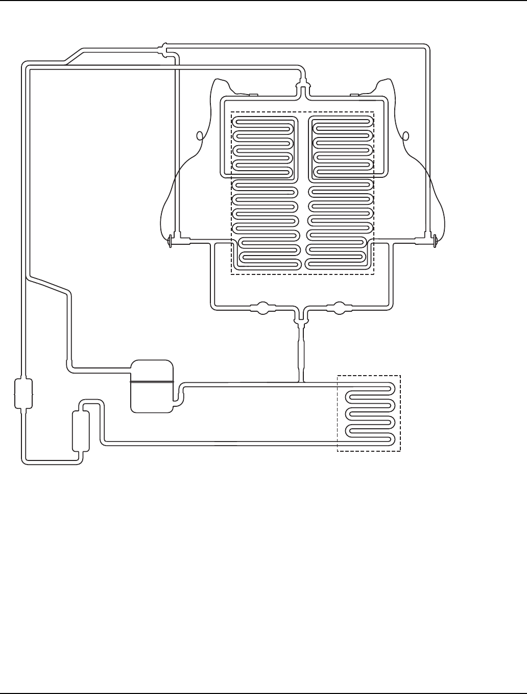
Refrigeration System Section 7
7-6 Part Number 80-1480-3
S1400/S1600/S1800 SELF-CONTAINED TUBING SCHEMATIC
NOTE: The refrigeration sequence for self-contained
dual expansion valve ice machines is identical to self-
contained single expansion valve ice machines. See
Pages 7-1 and 7-2 for sequence of operation.
x
x
HARVEST
SOLENOID VALVE
AIR OR WATER COOLED
CONDENSER
COMPRESSOR
HEAT
EXCHANGER
RECEIVER
DRIER
STRAINER
EXPANSION VALVE EXPANSION VALVE
EVAPORATOR
HARVEST
SOLENOID VALVE
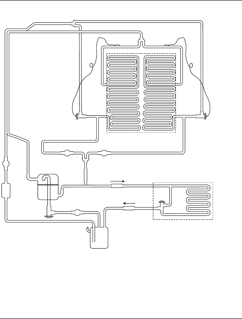
Section 7 Refrigeration System
Part Number 80-1480-3 7-7
S1400/S1600/S1800 REMOTE TUBING SCHEMATIC
NOTE: The refrigeration sequence for remote dual
expansion valve ice machines is identical to remote
single expansion valve ice machines. See Pages 7-3,
7-4, and 7-5 for sequence of operation.
REMOTE
CONDENSER
COMPRESSOR
HEAT
EXCHANGER
RECEIVER
DRIER
EXPANSION VALVE EXPANSION VALVE
EVAPORATOR
x
HPR VALVE
LLSV
CHECK VALVE
CHECK VALVE
x
x
HARVEST
SOLENOID VALVE
STRAINER
HARVEST
SOLENOID VALVE
HEAD
PRESSURE
CONTROL
VALVE

Refrigeration System Section 7
7-8 Part Number 80-1480-3
Operational Analysis (Diagnostics)
GENERAL
When analyzing the refrigeration system, it is important
to understand that different refrigeration component
malfunctions may cause very similar symptoms.
Also, many external factors can make good refrigeration
components appear bad. These factors can include
improper installation, or water system malfunctions such
as hot incoming water supply or water loss.
The following two examples illustrate how similar
symptoms can result in a misdiagnosis.
1. An expansion valve bulb that is not securely
fastened to the suction line and/or not insulated will
cause a good expansion valve to flood. If a service
technician fails to check for proper expansion valve
bulb mounting, he may replace the expansion valve
in error.
The ice machine now functions normally. The
technician erroneously thinks that the problem was
properly diagnosed and corrected by replacing the
expansion valve. Actually, the problem (loose bulb)
was corrected when the technician properly
mounted the bulb of the replacement expansion
valve.
The service technician’s failure to check the
expansion valve bulb for proper mounting (an
external check) resulted in a misdiagnosis and the
needless replacement of a good expansion valve.
2. An ice machine that is low on charge may cause a
good expansion valve to starve. If a service
technician fails to verify the system charge, he may
replace the expansion valve in error.
During the replacement procedure, recovery,
evacuation and recharging are performed correctly.
The ice machine now functions normally. The
technician erroneously thinks that the problem was
properly diagnosed and corrected by replacing the
expansion valve.
The service technician’s failure to check the ice
machine for a low charge condition resulted in a
misdiagnosis and the needless replacement of a
good expansion valve.
When analyzing the refrigeration system, use the
Refrigeration System Operational Analysis Table. This
table, along with detailed checklists and references, will
help prevent replacing good refrigeration components
due to external problems.

Section 7 Refrigeration System
Part Number 80-1480-3 7-9
BEFORE BEGINNING SERVICE
Ice machines may experience operational problems only
during certain times of the day or night. A machine may
function properly while it is being serviced, but
malfunctions later. Information provided by the user can
help the technician start in the right direction, and may
be a determining factor in the final diagnosis.
Ask these questions before beginning service:
• When does the ice machine malfunction? (night, day,
all the time, only during the freeze cycle, etc.)
• When do you notice low ice production? (one day a
week, every day, on weekends, etc.)
• Can you describe exactly what the ice machine
seems to be doing?
• Has anyone been working on the ice machine?
• During “store shutdown,” is the circuit breaker, water
supply or air temperature altered?
• Is there any reason why incoming water pressure
might rise or drop substantially?
ICE PRODUCTION CHECK
The amount of ice a machine produces directly relates to
the operating water and air temperatures. This means
an ice machine in a 70°F (21.1°C) room with 50°F
(10.0°C) water produces more ice than the same model
condensing unit with a 90°F (32.2°C) outdoor ambient
temperature and 70°F (21.1°C) water.
1. Determine the ice machine operating conditions:
Air temp. entering condenser: _______ °
Air temp. around ice machine: _______ °
Water temp. entering sump trough: _______ °
2. Refer to the appropriate 24 Hour Ice Production
Chart. Use the operating conditions determined in
Step 1 to find published 24 hour ice production.
3. Perform an actual ice production check. Use the
formula below.
4. Compare the results of step 3 with step 2. Ice
production checks that are within 10% of the chart
are considered normal. If they match closely,
determine if:
• another ice machine is required.
• more storage capacity is required.
• relocating the existing equipment to lower the
load conditions is required.
Contact the local Manitowoc distributor for
information on available options and accessories.
1. __________
Freeze Time
+ __________
Harvest Time
= __________
Total Cycle Time
2. 1440
Minutes in 24
Hours
÷ __________
Total Cycle Time
= __________
Cycles Per Day
3. __________
Weight of One
Harvest
x __________
Cycles Per Day
= __________
Actual 24 Hour Ice
Production
Important
Times are in minutes.
Example: 1 min., 15 sec. converts to 1.25 min.
(15 seconds ÷ 60 seconds = .25 minutes)
Weights are in pounds.
Example: 2 lb., 6 oz. converts to 2.375 lb.
(6 oz. ÷ 16 oz. = .375 lb.)
Weighing the ice is the only 100% accurate
check. However, if the ice pattern is normal and the
1/8" thickness is maintained, the ice slab weights
listed with the 24 Hour Ice Production Charts may
be used.

Refrigeration System Section 7
7-10 Part Number 80-1480-3
INSTALLATION/VISUAL INSPECTION CHECKLIST WATER SYSTEM CHECKLIST
A water-related problem often causes the same
symptoms as a refrigeration system component
malfunction.
Water system problems must be identified and
eliminated prior to replacing refrigeration components.
Possible Problem Corrective Action
Ice machine is not level Level the ice machine
Condenser is dirty Clean the condenser
Water filtration is plugged (if
used) Install a new water filter
Water drains are not run
separately and/or are not
vented
Run and vent drains
according to the Installation
Manual
Line set is improperly
installed Reinstall according to the
Installation Manual
Possible Problem Corrective Action
Water area (evaporator) is
dirty Clean as needed
Water inlet pressure not
between 20 and 80 psi
(1-5 Bar, 138- 552 kPa)
Install a water regulator valve
or increase the water
pressure
Incoming water temperature
is not between 35°F (1.6°C)
and 90°F (32.2°C).
If too hot, check the hot water
line check valves in other
store equipment
Water filtration is plugged (if
used) Install a new water filter
Water dump valve leaking
during the freeze cycle Clean/replace dump valve as
needed
Vent tube is not installed on
water outlet drain See Installation Instructions
Hoses, fittings, etc., are
leaking water Repair/replace as needed
Water fill valve is stuck open Clean/replace as needed
Water is spraying out of the
sump trough area Stop the water spray
Uneven water flow across the
evaporator Clean the ice machine
Water is freezing behind the
evaporator Correct the water flow
Plastic extrusions and
gaskets are not secured to
the evaporator
Remount/replace as needed
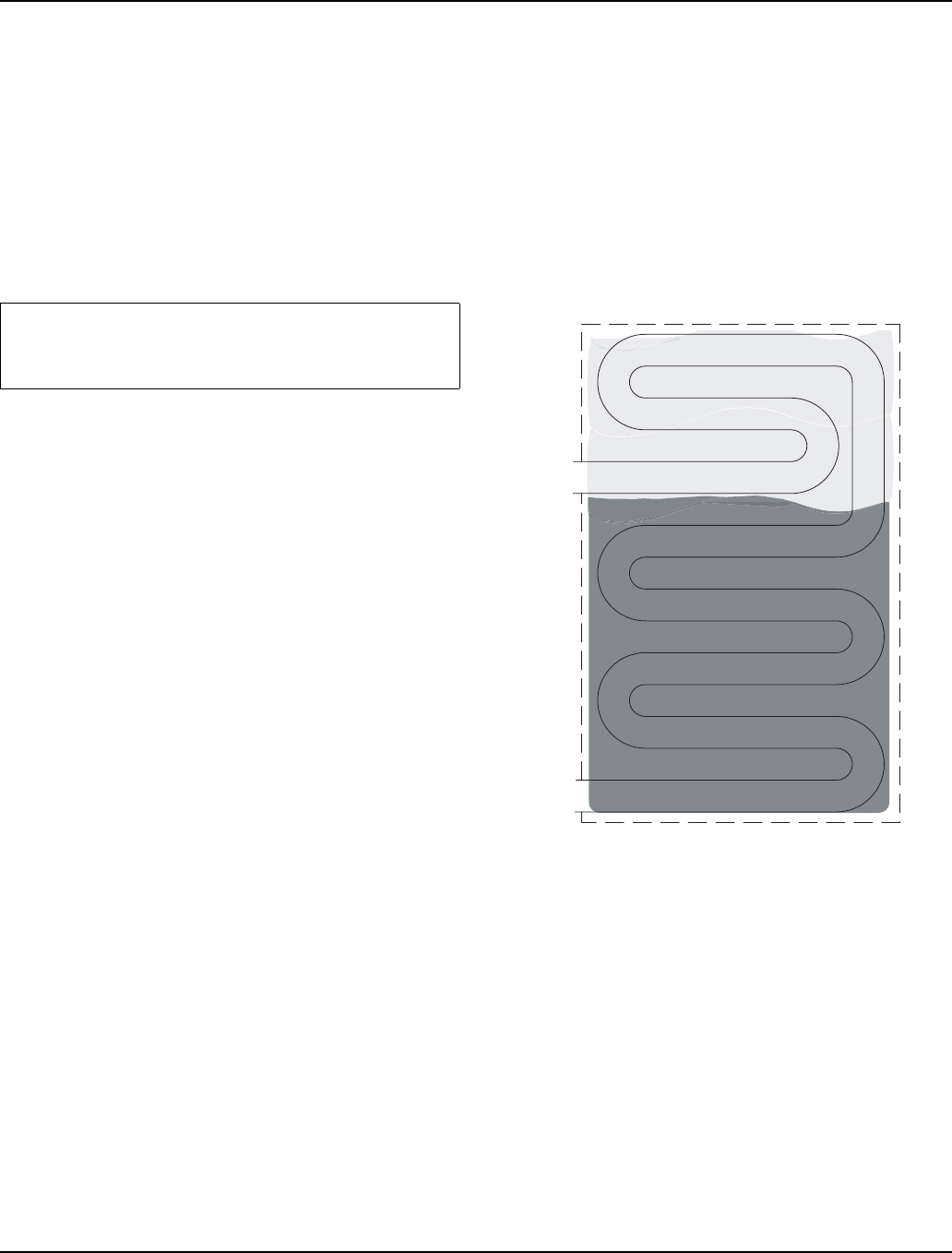
Section 7 Refrigeration System
Part Number 80-1480-3 7-11
ICE FORMATION PATTERN
Evaporator ice formation pattern analysis is helpful in ice
machine diagnostics.
Analyzing the ice formation pattern alone cannot
diagnose an ice machine malfunction. However, when
this analysis is used along with Manitowoc’s
Refrigeration System Operational Analysis Table, it can
help diagnose an ice machine malfunction.
Improper ice formation can be caused by any number of
problems.
1. Normal Ice Formation
Ice forms across the entire evaporator surface.
At the beginning of the freeze cycle, it may appear that
more ice is forming at the inlet of the evaporator than at
the outlet. At the end of the freeze cycle, ice formation at
the outlet will be close to, or just a bit thinner than, ice
formation at the inlet. The dimples in the cubes at the
outlet of the evaporator may be more pronounced than
those at the inlet. This is normal.
The ice thickness probe must be set to maintain the ice
bridge thickness at approximately 1/8". If ice forms
uniformly across the evaporator surface, but does not
reach 1/8" in the proper amount of time, this is still
considered normal.
2. Extremely Thin at Evaporator Outlet
There is no ice, or a considerable lack of ice formation at
the outlet of the evaporator.
Examples: No ice at all at the outlet half of the
evaporator, but ice forms at the inlet half of the
evaporator. Or, the ice at the outlet of the evaporator
reaches 1/8" to initiate a harvest, but the inlet of the
evaporator already has 1/2" to 1" of ice formation.
Possible cause: Water loss, low on refrigerant, starving
TXV, faulty water fill valve etc.
Figure 7-6. Extremely Thin Ice Formation at
Evaporator Outlet
Important
Keep the water curtain in place while checking the
ice formation pattern to ensure no water is lost.
OUTLET
INLET
NO ICE or THIN ICE
ICE
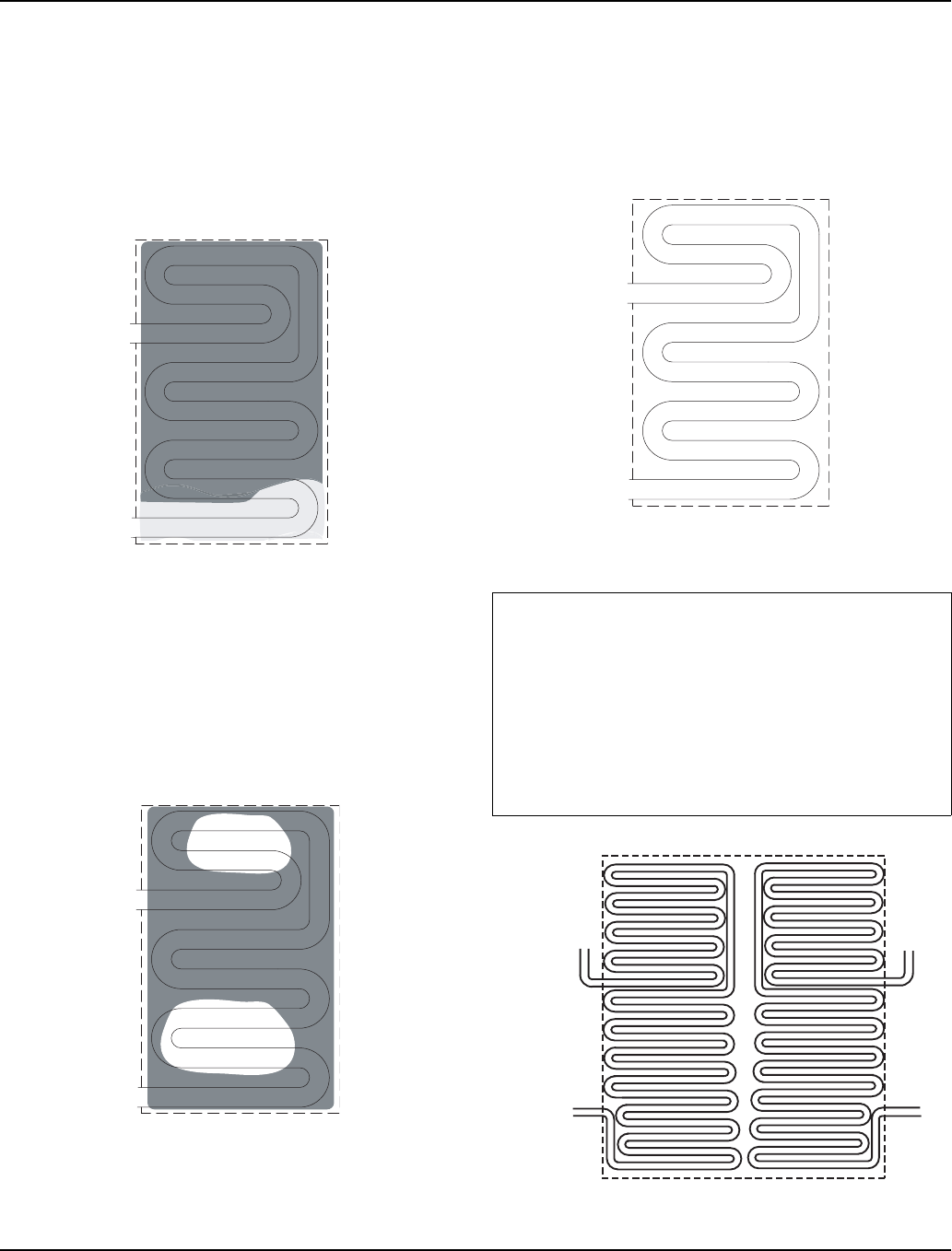
Refrigeration System Section 7
7-12 Part Number 80-1480-3
3. Extremely Thin at Evaporator Inlet
There is no ice, or a considerable lack of ice formation at
the inlet of the evaporator. Examples: The ice at the
outlet of the evaporator reaches 1/8" to initiate a harvest,
but there is no ice formation at all at the inlet of the
evaporator.
Possible causes: Insufficient water flow, flooding TXV,
etc.
Figure 7-7. Extremely Thin Ice Formation at
Evaporator Inlet
4. Spotty Ice Formation
There are small sections on the evaporator where there
is no ice formation. This could be a single corner, or a
single spot in the middle of the evaporator. This is
generally caused by loss of heat transfer from the tubing
on the back side of the evaporator.
Figure 7-8. Spotty Ice Formation
5. No Ice Formation
The ice machine operates for an extended period, but
there is no ice formation at all on the evaporator.
Possible causes: Water inlet valve, water pump, starving
expansion valve, low refrigerant charge, compressor,
etc.
Figure 7-9. No Ice Formation
Figure 7-10. S1400/S1600/S1800 Evaporator Tubing
OUTLET
INLET
ICE
OUTLET
INLET
ICE
Important
The S1400 S1600 and S1800 model machines
have left and right expansion valves and separate
evaporator circuits. These circuits operate
independently from each other. Therefore, one may
operate properly while the other is malfunctioning.
Example: If the left expansion valve is starving, it
may not affect the ice formation pattern on the entire
right side of the evaporator.
OUTLET
INLET
OUTLET
INLET

Section 7 Refrigeration System
Part Number 80-1480-3 7-13
SAFETY LIMITS
General
In addition to standard safety controls, such as high
pressure cut-out, the control board has two built in safety
limit controls which protect the ice machine from major
component failures.
Safety Limit #1: If the freeze time reaches 60 minutes,
the control board automatically initiates a harvest cycle.
If 6 consecutive 60-minute freeze cycles occur, the ice
machine stops.
Safety Limit #2: If the harvest time reaches 3.5 minutes,
the control board automatically returns the ice machine
to the freeze cycle.
If 500 consecutive 3.5 minute harvest cycles occur, the
ice machine stops.
Safety Limit Indication
When a safety limit condition is exceeded:
• Six consecutive cycles for safety limit 1 - the
control board enters the limit into memory.
• Three consecutive cycles for safety limit 2 - the
control board enters the limit into memory and
the ice machine continues to run.
Use the following procedures to determine if the control
board contains a safety limit indication.
1. Move the toggle switch to OFF.
2. Move the toggle switch back to ICE.
3. Watch the safety limit lights (SL-1 and SL-2). If a
safety limit has been recorded, either the SL-1 light
will flash once or the SL-2 light will flash twice,
corresponding to safety limit 1 or 2 to indicate which
safety limit stopped the ice machine.
Analyzing Why Safety Limits May Stop the Ice
Machine
According to the refrigeration industry, a high percentage
of compressors fail as a result of external causes. These
can include: flooding or starving expansion valves, dirty
condensers, water loss to the ice machine, etc. The
safety limits protect the ice machine (primarily the
compressor) from external failures by stopping ice
machine operation before major component damage
occurs.
The safety limit system is similar to a high pressure cut-
out control. It stops the ice machine, but does not tell
what is wrong. The service technician must analyze the
system to determine what caused the high pressure cut-
out, or a particular safety limit, to stop the ice machine.
The safety limits are designed to stop the ice machine
prior to major component failures, most often a minor
problem or something external to the ice machine. This
may be difficult to diagnose, as many external problems
occur intermittently.
Example: An ice machine stops intermittently on safety
limit #1 (long freeze times). The problem could be a low
ambient temperature at night, a water pressure drop, the
water is turned off one night a week, etc.
Refrigeration and electrical component failures may also
trip a safety limit. Eliminate all electrical components and
external causes first. If it appears that the refrigeration
system is causing the problem, use Manitowoc’s
Refrigeration System Operational Analysis Table, along
with detailed charts, checklists, and other references to
determine the cause.
The following checklists are designed to assist the
service technician in analysis. However, because there
are many possible external problems, do not limit your
diagnosis to only the items listed.

Refrigeration System Section 7
7-14 Part Number 80-1480-3
Safety Limit #1
Refer to previous page for safety limit operation.
Freeze time exceeds 60 minutes for 6 consecutive freeze cycles.
SAFETY LIMIT NOTES
• Because there are many possible external problems,
do not limit your diagnosis to only the items listed in
this chart.
• A continuous run of 100 harvests automatically
erases the safety limit code.
• The control board will store and indicate only one
safety limit – the last one exceeded.
• If the toggle switch is moved to the OFF position and
then back to the ICE position prior to reaching the
100-harvest point, the last safety limit exceeded will
be indicated.
• If a Safety Limit light did not flash prior to the ice
machine restarting, then the ice machine did not stop
because it exceeded a safety limit.
Possible Cause Check/Correct
Improper installation See “Installation/Visual Inspection Checklist”
Water system Low water pressure [20 psi (138 kPa) min.]
High water pressure [80 psi (552 kPa) max.]
High water temperature (90°F/32.2°C max.)
Clogged water distribution tube
Dirty/defective water fill valve
Dirty/defective water dump valve
Defective water pump
Loss of water from sump area
Electrical system Low incoming voltage
Ice thickness probe out of adjustment
Harvest cycle not initiated electrically
Contactor not energizing
Compressor electrically non-operational
Defective fan cycling control
Defective fan motor
Miscellaneous Restricted condenser airflow
High inlet air temperature (Self-Contained -110°F/43.3°C max.;
Remote - 120°F/49°C max.)
Condenser discharge air recirculation
Dirty condenser filter
Dirty condenser
Restricted condenser water flow
Low water pressure [20 psi (138 kPa) min.]
High water temperature (90°F/32.2°C max.)
Dirty/defective water regulating valve
Water regulating valve out of adjustment
Refrigeration system Improper refrigerant charge
Non-Manitowoc components
Defective head pressure control (remotes)
Defective harvest valve
Defective compressor
TXV starving or flooding (check bulb mounting)
Non-condensables in refrigeration system
Plugged or restricted high side refrigerant lines or component

Section 7 Refrigeration System
Part Number 80-1480-3 7-15
Safety Limit #2
Refer to page 7-11 for safety limit operation.
Harvest time exceeds 3.5 minutes for 500 consecutive harvest cycles.
SAFETY LIMIT NOTES
• Because there are many possible external problems,
do not limit your diagnosis to only the items listed in
this chart.
• A continuous run of 100 harvests automatically
erases the safety limit code.
• The control board will store and indicate only one
safety limit – the last one exceeded.
• If the toggle switch is moved to the OFF position and
then back to the ICE position prior to reaching the
100-harvest point, the last safety limit exceeded will
be indicated.
• If a Safety Limit light did not flash prior to the ice
machine restarting, then the ice machine did not stop
because it exceeded a safety limit.
Possible Cause Check/Correct
Improper installation See “Installation/Visual Inspection Checklist”
Water system Water area (evaporator) dirty
Dirty/defective water dump valve
Vent tube not installed on water outlet drain
Water freezing behind evaporator
Plastic extrusions and gaskets not securely mounted to the
evaporator
Low water pressure [20 psi (138 kPa) min.]
Loss of water from sump area
Clogged water distribution tube
Dirty/defective water fill valve
Defective water pump
Electrical system Ice thickness probe out of adjustment
Ice thickness probe dirty
Bin switch defective
Premature harvest
Refrigeration system Non-Manitowoc components
Water regulating valve dirty/defective
Improper refrigerant charge
Defective head pressure control valve (remotes)
Defective harvest pressure control (HPR) valve (remotes)
Defective harvest valve
TXV flooding (check bulb mounting)
Defective fan cycling control

Refrigeration System Section 7
7-16 Part Number 80-1480-3
ANALYZING DISCHARGE PRESSURE
DURING FREEZE OR HARVEST CYCLE
Procedure
1. Determine the ice machine operating conditions:
Air temp. entering condenser ______
Air temp. around ice machine ______
Water temp. entering sump trough ______
2. Refer to Operating Pressure Chart for ice machine
being checked.
Use the operating conditions determined in step 1 to
find the published normal discharge pressures.
Freeze Cycle _______ Harvest Cycle _______
3. Perform an actual discharge pressure check.
4. Compare the actual discharge pressure (step 3) with
the published discharge pressure (step 2).
The discharge pressure is normal when the actual
pressure falls within the published pressure range for the
ice machine’s operating conditions.
Freeze Cycle Discharge Pressure High Checklist
Freeze Cycle Discharge Pressure Low Checklist
NOTE: Do not limit your diagnosis to only the items listed in the checklists.
Freeze Cycle
PSIG (kPa) Harvest Cycle
PSIG (kPa)
Beginning of Cycle __________ __________
Middle of Cycle __________ __________
End of Cycle __________ __________
Possible Cause Check/Correct
Improper installation See “Installation/Visual Inspection Checklist”
Restricted condenser air flow (air-cooled models) High inlet air temperature (Self-Contained -110°F/43.3°C max.;
Remote - 120°F/49°C max.)
Condenser discharge air recirculation
Dirty condenser filter
Dirty condenser
Defective fan cycling control
Defective fan motor
Restricted condenser water flow (water-cooled
models) Low water pressure [20 psi (138 kPa) min.]
High inlet water temperature (90°F/32.2°C max.)
Dirty condenser
Dirty/defective water regulating valve
Water regulating valve out of adjustment
Improper refrigerant charge Overcharged
Non-condensables in system
Wrong type of refrigerant
Other Non-Manitowoc components in system
High side refrigerant lines/component restricted (before mid-condenser)
Defective head pressure control valve (remote models)
Possible Cause Check/Correct
Improper installation See “Installation/Visual Inspection Checklist”
Improper refrigerant charge Undercharged
Wrong type of refrigerant
Water regulating valve (water-cooled condensers) Out of adjustment
Defective
Other Non-Manitowoc components in system
Defective head pressure control valve (remote models)
Defective fan cycle control
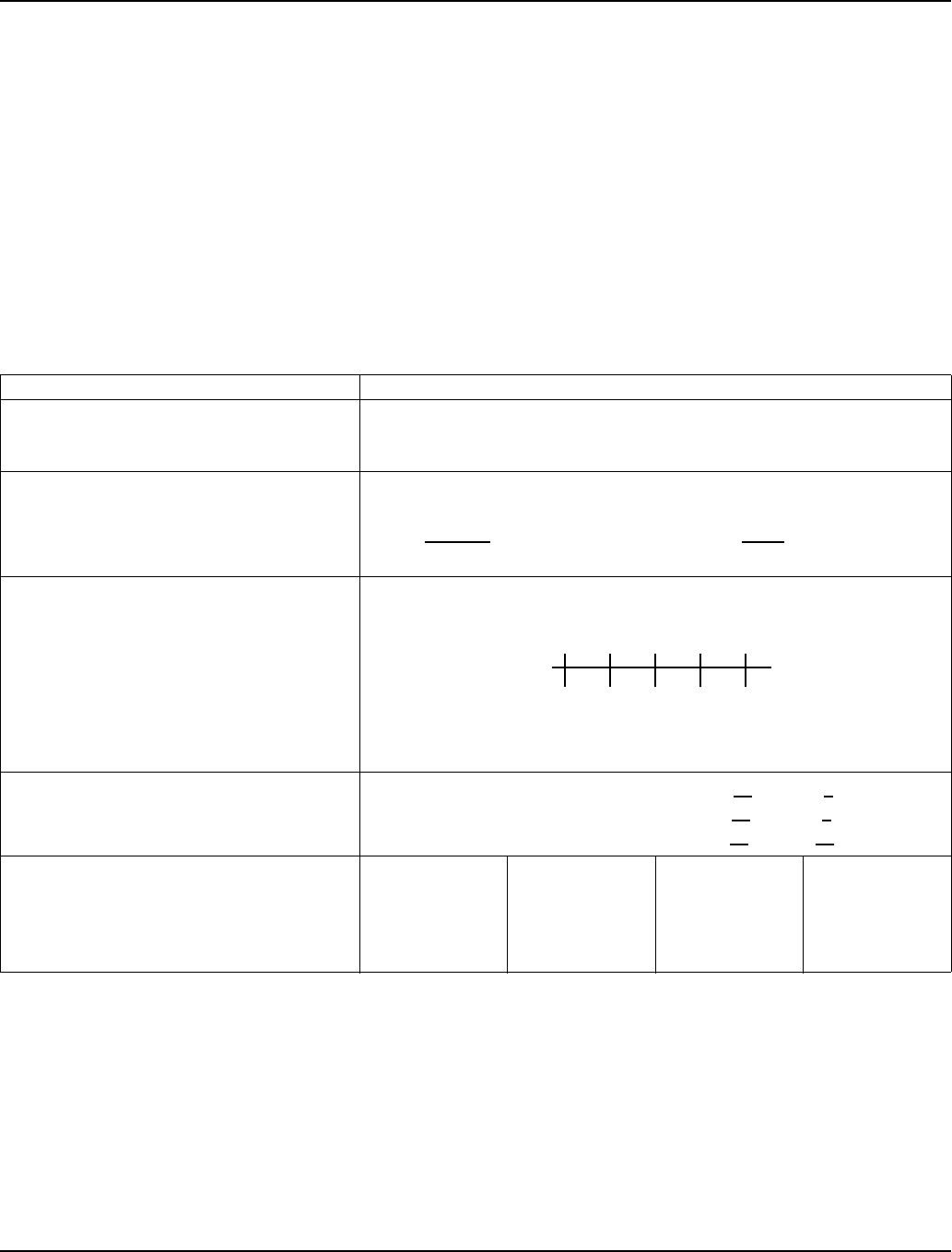
Section 7 Refrigeration System
Part Number 80-1480-3 7-17
ANALYZING SUCTION PRESSURE
DURING FREEZE CYCLE
The suction pressure gradually drops throughout the
freeze cycle. The actual suction pressure (and drop rate)
changes as the air and water temperatures entering the
ice machine change. This affects freeze cycle times.
To analyze and identify the proper suction pressure drop
throughout the freeze cycle, compare the published
suction pressure to the published freeze cycle time.
“Operating Pressure” and “Freeze Cycle Time” charts
can be found later in this section.
NOTE: Analyze discharge pressure before analyzing
suction pressure. High or low discharge pressure may
be causing high or low suction pressure.
Procedure
Step Example Using SY1004A Model Ice Machine
1. Determine the ice machine operating
conditions.
Air temp. entering condenser: 90°F/32.2°C
Air temp. around ice machine: 80°F/26.7°C
Water temp. entering water fill valve: 70°F/21.1°C
2A. Refer to “Cycle Time” and “Operating
Pressure” charts for ice machine model being
checked. Using operating conditions from Step
1, determine published freeze cycle time and
published freeze cycle suction pressure.
Published freeze cycle time: Published freeze cycle suction pressure:
8.5 - 9.8 minutes 58-28 PSIG
2B. Compare the published freeze cycle time
and published freeze cycle suction pressure.
Develop a chart.
Published Freeze Cycle Time (minutes)
Published Freeze Cycle Suction Pressure (psig)
3. Perform an actual suction pressure check at
the beginning, middle and end of the freeze
cycle. Note the times at which the readings are
taken.
Beginning of freeze cycle: 70 PSIG at 1 minute
Middle of freeze cycle: 57 PSIG at 7 minutes
End of freeze cycle: 40 PSIG at 14 minutes
4. Compare the actual freeze cycle suction
pressure (Step 3) to the published freeze cycle
time and pressure comparison (Step 2B).
Determine if the suction pressure is high, low
or acceptable.
Time Into
Freeze Cycle Published
Pressure Actual
Pressure Result
1 minutes
5 minutes
10 minutes
58 PSIG
43 PSIG
28 PSIG
70 PSIG
48 PSIG
40 PSIG
High
High
High
13 5810
58 52 43 33 28

Refrigeration System Section 7
7-18 Part Number 80-1480-3
Freeze Cycle Suction Pressure High Checklist
Freeze Cycle Suction Pressure Low Checklist
NOTE: Do not limit your diagnosis to only the items listed in the checklists.
Possible Cause Check/Correct
Improper installation See “Installation/Visual Inspection Checklist”
Discharge pressure Discharge pressure is too high, and is affecting low side
(See “Freeze Cycle Discharge Pressure High Checklist” )
Improper refrigerant charge Overcharged
Wrong type of refrigerant
Other Non-Manitowoc components in system
H.P.R. solenoid leaking
Harvest valve stuck open
TXV flooding (check bulb mounting)
Defective compressor
Possible Cause Check/Correct
Improper installation See “Installation/Visual Inspection Checklist”
Discharge pressure Discharge pressure is too low, and is affecting low side
(See “Freeze Cycle Discharge Pressure Low Checklist”)
Improper refrigerant charge Undercharged
Wrong type of refrigerant
Other Non-Manitowoc components in system
Improper water supply over evaporator (See “Water System Checklist” )
Loss of heat transfer from tubing on back side of evaporator
Restricted/plugged liquid line drier
Restricted/plugged tubing in suction side of refrigeration system
TXV starving

Section 7 Refrigeration System
Part Number 80-1480-3 7-19
SINGLE EXPANSION VALVE ICE MACHINES -
COMPARING EVAPORATOR INLET AND
OUTLET TEMPERATURES
NOTE: This procedure will not work on the dual
expansion valve ice machines.
The temperatures of the suction lines entering and
leaving the evaporator alone cannot diagnose an ice
machine. However, comparing these temperatures
during the freeze cycle, along with using Manitowoc’s
Refrigeration System Operational Analysis Table, can
help diagnose an ice machine malfunction.
The actual temperatures entering and leaving the
evaporator vary by model, and change throughout the
freeze cycle. This makes documenting the “normal” inlet
and outlet temperature readings difficult. The key to the
diagnosis lies in the difference between the two
temperatures five minutes into the freeze cycle. These
temperatures must be within 7° of each other.
Use this procedure to document freeze cycle inlet and
outlet temperatures.
1. Use a quality temperature meter, capable of taking
temperature readings on curved copper lines.
2. Attach the temperature meter sensing device to the
copper lines entering and leaving the evaporator.
3. Wait five minutes into the freeze cycle.
4. Record the temperatures below and determine the
difference between them.
5. Use this with other information gathered on the
Refrigeration System Operational Analysis Table to
determine the ice machine malfunction.
Important
Do not simply insert the sensing device under the
insulation. It must be attached to and reading the
actual temperature of the copper line.
______________
Inlet Temperature ______________
Outlet Temperature
_______________
Difference
Must be within 7° at 5
minutes into freeze cycle

Refrigeration System Section 7
7-20 Part Number 80-1480-3
HARVEST VALVE TEMPERATURE CHECK
General
NOTE: This procedure requires checking both harvest
valves on dual expansion valve S1400 and S1800 ice
machines.
A harvest valve requires a critical orifice size. This
meters the amount of hot gas flowing into the evaporator
during the harvest cycle. If the orifice is even slightly too
large or too small, long harvest cycles will result.
A too-large orifice causes refrigerant to condense to
liquid in the evaporator during the harvest cycle. This
liquid will cause compressor damage. A too-small orifice
does not allow enough hot gas into the evaporator. This
causes low suction pressure, and insufficient heat for a
harvest cycle.
Refer to the Parts Manual for proper valve application. If
replacement is necessary, Use only “original” Manitowoc
replacement parts.
Harvest Valve Analysis
Symptoms of a harvest valve remaining partially open
during the freeze cycle can be similar to symptoms of
either an expansion valve or compressor problem. The
best way to diagnose a harvest valve is by using
Manitowoc’s Ice Machine Refrigeration System
Operational Analysis Table.
Use the following procedure and table to help determine
if a harvest valve is remaining partially open during the
freeze cycle.
1. Wait five minutes into the freeze cycle.
2. Feel the inlet of the harvest valve(s).
3. Feel the compressor discharge line.
4. Compare the temperature of the inlet of the harvest
valves to the temperature of the compressor
discharge line.
Important
Feeling the harvest valve outlet or across the
harvest valve itself will not work for this comparison.
The harvest valve outlet is on the suction side (cool
refrigerant). It may be cool enough to touch even if
the valve is leaking.
!
Warning
The inlet of the harvest valve and the compressor
discharge line could be hot enough to burn your
hand. Just touch them momentarily.
Findings Comments
The inlet of the
harvest valve is cool
enough to touch and
the compressor
discharge line is hot.
This is normal as the discharge line
should always be too hot to touch and
the harvest valve inlet, although too
hot to touch during harvest, should be
cool enough to touch after 5 minutes
into the freeze cycle.
The inlet of the
harvest valve is hot
and approaches the
temperature of a hot
compressor
discharge line.
This is an indication something is
wrong, as the harvest valve inlet did
not cool down during the freeze cycle.
If the compressor dome is also entirely
hot, the problem is not a harvest valve
leaking, but rather something causing
the compressor (and the entire ice
machine) to get hot.
Both the inlet of the
harvest valve and
the compressor
discharge line are
cool enough to
touch.
This is an indication something is
wrong, causing the compressor
discharge line to be cool to the touch.
This is not caused by a harvest valve
leaking.

Section 7 Refrigeration System
Part Number 80-1480-3 7-21
DISCHARGE LINE TEMPERATURE ANALYSIS
General
Knowing if the discharge line temperature is increasing,
decreasing or remaining constant can be an important
diagnostic tool. Maximum compressor discharge line
temperature on a normally operating ice machine
steadily increases throughout the freeze cycle.
Comparing the temperatures over several cycles will
result in a consistent maximum discharge line
temperature.
Ambient air temperatures affect the maximum discharge
line temperature.
Higher ambient air temperatures at the condenser and/
or higher inlet water temperature = higher discharge line
temperatures at the compressor.
Lower ambient air temperatures at the condenser and/or
lower supply water temperature= lower discharge line
temperatures at the compressor.
Regardless of ambient and water temperatures, the
freeze cycle discharge line temperature will be higher
than 160°F (71.1°C) [S850/S1000 Air & Water Machines
Only - 140°F (60°C)] on a normally operating ice
machine.
Procedure
Connect a temperature probe on the compressor
discharge line with-in 6" of the compressor and insulate.
Observe the discharge line temperature for the last three
minutes of the freeze cycle and record the maximum
discharge line temperature.
Discharge Line Temperature Above 160°F (71.1°C) At
End Of Freeze Cycle:
Ice machines that are operating normally will have
consistent maximum discharge line temperatures above
160°F (71.1°C).
Discharge Line Temperature Below 160°F (71.1°C) At
End Of Freeze Cycle
Ice machines that have a flooding expansion valve will
have a maximum discharge line temperature that
decreases each cycle.
Verify the expansion valve sensing bulb is 100%
insulated and sealed airtight. Condenser air contacting
an incorrectly insulated sensing bulb will cause
overfeeding of the expansion valve.
Verify the expansion valve sensing bulb is positioned
and secured correctly.
S850/S1000 Air and Water Ice Machines Only:
Discharge Line Temperature Above 140°F (60°C) At
End Of Freeze Cycle:
Ice machines that are operating normally will have
consistent maximum discharge line temperatures above
140°F (60°C).
Discharge Line Temperature Below 140°F (60°C) At
End Of Freeze Cycle
Ice machines that have a flooding expansion valve will
have a maximum discharge line temperature that
decreases each cycle.
Verify the expansion valve sensing bulb is 100%
insulated and sealed airtight. Condenser air contacting
an incorrectly insulated sensing bulb will cause
overfeeding of the expansion valve.
Verify the expansion valve sensing bulb is positioned
and secured correctly.

Refrigeration System Section 7
7-22 Part Number 80-1480-3
HOW TO USE THE REFRIGERATION SYSTEM
OPERATIONAL ANALYSIS TABLES
General
These tables must be used with charts, checklists and
other references to eliminate refrigeration components
not listed on the tables and external items and problems
which can cause good refrigeration components to
appear defective.
The tables list five different defects that may affect the
ice machine’s operation.
NOTE: A low-on-charge ice machine and a starving
expansion valve have very similar characteristics and
are listed under the same column.
NOTE: Before starting, see “Before Beginning Service”
for a few questions to ask when talking to the ice
machine owner.
Procedure
Step 1 Record the ice machine model number.
Step 2 Complete the “Operation Analysis” column.
Read down the left “Operational Analysis” column.
Perform all procedures and check all information listed.
Each item in this column has supporting reference
material to help analyze each step.
While analyzing each item separately, you may find an
“external problem” causing a good refrigerant
component to appear bad. Correct problems as they are
found. If the operational problem is found, it is not
necessary to complete the remaining procedures.
NOTE: Discharge Line Temperature will vary by model.
Refer to the model number to verify the correct
temperature to analyze.
Step 3 Enter check marks (√) in the small boxes.
Each time the actual findings of an item in the
“Operational Analysis” column matches the published
findings on the table, enter a check mark.
Example: Freeze cycle suction pressure is determined
to be low. Enter a check mark in the “low” box.
Step 4 Add the check marks listed under each of the
four columns. Note the column number with the highest
total and proceed to “Final Analysis.”
NOTE: If two columns have matching high numbers, a
procedure was not performed properly and/or supporting
material was not analyzed correctly.
Final Analysis
The column with the highest number of check marks
identifies the refrigeration problem.
COLUMN 1 - HARVEST VALVE LEAKING
A leaking harvest valve must be replaced.
COLUMN 2 - LOW CHARGE/TXV STARVING
Normally, a starving expansion valve only affects the
freeze cycle pressures, not the harvest cycle pressures.
A low refrigerant charge normally affects both pressures.
Verify the ice machine is not low on charge before
replacing an expansion valve.
1. Add refrigerant charge in 2 to 4 oz. increments as a
diagnostic procedure to verify a low charge. If the
problem is corrected, the ice machine is low on
charge. Find the refrigerant leak.
The ice machine must operate with the nameplate
charge. If the leak cannot be found, proper
refrigerant procedures must still be followed Change
the liquid line drier. Then, evacuate and weigh in the
proper charge.
2. If the problem is not corrected by adding charge, the
expansion valve is faulty.
On dual expansion valve ice machines, change only
the TXV that is starving. If both TXV’s are starving,
they are probably good and they are being affected
by some other malfunction; such as low charge.
COLUMN 3 - TXV FLOODING
A loose or improperly mounted expansion valve bulb
causes the expansion valve to flood. Check bulb
mounting, insulation, etc., before changing the valve. On
dual expansion valve machines, the service technician
should be able to tell which TXV is flooding by analyzing
ice formation patterns. Change only the flooding
expansion valve.
COLUMN 4 - COMPRESSOR
Replace the compressor and start components. To
receive warranty credit, the compressor ports must be
properly sealed by crimping and soldering them closed.
Old start components must be returned with the faulty
compressor.
Section 7 Refrigeration System
Part Number 80-1480-3 7-23
REFRIGERATION SYSTEM OPERATIONAL ANALYSIS TABLES
S Models Single Expansion Valve - Ice Machine Model Number_________________
This table must be used with charts, checklists and other references to eliminate refrigeration
components not listed on the table and external items and problems, which can cause good
refrigeration components to appear defective.
Operational Analysis 1 2 3 4
Ice Production Air-Temperature Entering Condenser_____________
Water Temperature Entering Ice Machine_________
Published 24 hour ice production________________
Calculated (actual) ice production_______________
NOTE: The ice machine is operating properly if the ice fill patterns is normal and ice production is within 10% of charted
capacity.
Installation and Water System All installation and water related problems must be corrected before proceeding with chart.
Ice Formation Pattern Ice formation is extremely
thin on outlet of evaporator
-or-
No ice formation on the
entire evaporator
Ice formation is extremely
thin on outlet of evaporator
-or-
No ice formation on entire
evaporator
Ice formation normal
-or-
Ice formation is extremely
thin on inlet of evaporator
-or-
No ice formation on entire
evaporator
Ice formation normal
-or-
No ice formation on entire
evaporator
Safety Limits
Refer to “Analyzing Safety Limits” to
eliminate all non-refrigeration
problems.
Stops on safety limit:
1Stops on safety limit:
1Stops on safety limit:
1 or 2 Stops on safety limit:
1
Freeze Cycle
Discharge Pressure
_____ ______ ______
1 minute Middle End
into cycle
If discharge pressure is High or Low refer to freeze cycle high or low discharge pressure problem checklist to eliminate
problems and/or components not listed on this table before proceeding.
Freeze Cycle
Suction Pressure
_____ ______ ______
1 minute Middle End
If suction pressure is High or Low refer to freeze cycle high or low suction pressure problem checklist to eliminate
problems and/or components not listed on this table before proceeding.
Suction pressure is High Suction pressure is Low or
Normal Suction pressure is High Suction pressure is High
Wait 5 minutes into the freeze cycle.
Compare temperatures of
evaporator inlet & evaporator
outlet.
Inlet ____ ° F (° C)
Outlet ____ ° F (° C)
Difference ____ ° F (° C)
Inlet and outlet
within 7°
of each other
Inlet and outlet
not within 7°
of each other
-and-
Inlet is colder than outlet
Inlet and outlet
within 7°
of each other
-or-
Inlet and outlet
not within 7°
of each other
-and-
Inlet is warmer than outlet
Inlet and outlet
within 7°
of each other
Wait 5 minutes into the freeze cycle.
Compare temperatures of
compressor discharge line
and harvest valve inlet.
The harvest valve inlet is
Hot
-and-
approaches the temperature
of a Hot compressor
discharge line.
The harvest valve inlet is
Cool enough to hold hand
on
-and-
the compressor discharge
line is Hot.
The harvest valve inlet is
Cool enough to hold hand
on
-and-
the compressor discharge
line is Cool
enough to hold hand on.
The harvest valve inlet is
Cool enough to hold hand
on
-and-
the compressor discharge
line is Hot.
Discharge Line Temperature
Record freeze cycle discharge line
temperature at the end of the freeze
cycle
_________°F (°C)
Discharge line temperature
160°F (71.1°C)
or higher at the end of the
freeze cycle
--------------------------------------
S850/S1000
Air & Water Only
Discharge line temperature
140°F (60°C) or higher at
the end of the freeze cycle
Discharge line temperature
160°F (71.1°C)
or higher at the end of the
freeze cycle
-------------------------------------
S850/S1000
Air & Water Only
Discharge line temperature
140°F (60°C)
or higher at the end of the
freeze cycle
Discharge line temperature
less than
160°F (71.1°C) at the end
of the freeze cycle
-------------------------------------
S850/S1000
Air & Water Only
Discharge line temperature
less than
140°F (60°C) at the end of
the freeze cycle
Discharge line
temperature 160°F
(71.1°C) or higher at the
end of the freeze cycle
-----------------------------------
S850/S1000
Air & Water Only
Discharge line
temperature 140°F (60°C)
or higher at the end of
the freeze cycle
Final Analysis
Enter total number of boxes checked
in each column.
Harvest Valve Leaking Low On Charge
-Or-
TXV Starving TXV Flooding Compressor

Refrigeration System Section 7
7-24 Part Number 80-1480-3
REFRIGERATION SYSTEM OPERATIONAL ANALYSIS TABLES
S Models Dual Expansion Valve - Ice Machine Model Number_________________
This table must be used with charts, checklists and other references to eliminate refrigeration
components not listed on the table and external items and problems, which can cause good
refrigeration components to appear defective.
Operational Analysis 1 2 3 4
Ice Production Air-Temperature Entering Condenser_____________
Water Temperature Entering Ice Machine_________
Published 24 hour ice production________________
Calculated (actual) ice production_______________
NOTE: The ice machine is operating properly if the ice fill patterns is normal and ice production is within 10% of charted
capacity.
Installation and Water System All installation and water related problems must be corrected before proceeding with chart.
Ice Formation Pattern
Left Side__________________
Right Side_________________
Ice formation is extremely
thin on outlet of evaporator
-or-
No ice formation on the one
side of evaporator
Ice formation is extremely
thin on outlet of one side of
evaporator
-or-
No ice formation on entire
evaporator
Ice formation normal
-or-
Ice formation is extremely
thin at inlet of one side of
evaporator
-or-
No ice formation on entire
evaporator
Ice formation normal
-or-
No ice formation on entire
evaporator
Safety Limits
Refer to “Analyzing Safety Limits” to
eliminate all non-refrigeration
problems.
Stops on safety limit:
1 or 2 Stops on safety limit:
1 or 2 Stops on safety limit:
1 or 2 Stops on safety limit:
1 or 2
Freeze Cycle
Discharge Pressure
_____ ______ ______
1 minute Middle End
into cycle
If discharge pressure is High or Low refer to freeze cycle high or low discharge pressure problem checklist to eliminate
problems and/or components not listed on this table before proceeding.
Freeze Cycle
Suction Pressure
_____ ______ ______
1 minute Middle End
If suction pressure is High or Low refer to freeze cycle high or low suction pressure problem checklist to eliminate
problems and/or components not listed on this table before proceeding.
Suction pressure is
High Suction pressure is
Low or Normal Suction pressure is
High Suction pressure is
High
Wait 5 minutes into the freeze cycle.
Compare temperatures of
compressor discharge line
and both harvest valve inlets.
One harvest valve inlet is
Hot
-and-
approaches the temperature
of a Hot compressor
discharge line.
Both harvest valve inlets are
Cool enough to hold hand
on
-and-
the compressor discharge
line is Hot.
Both harvest valve inlets are
Cool enough to hold hand
on
-and-
the compressor discharge
line is Cool
enough to hold hand on.
Both harvest valve inlets
are Cool enough to hold
hand on
-and-
the compressor discharge
line is Hot.
Discharge Line Temperature
Record freeze cycle discharge line
temperature at the end of the freeze
cycle
_________°F (°C)
Discharge line temperature
160°F (71.1°C)
or higher at the end of the
freeze cycle
Discharge line temperature
160°F (71.1°C)
or higher at the end of the
freeze cycle
Discharge line temperature
less than
160°F (71.1°C) at the end
of the freeze cycle
Discharge line
temperature 160°F
(71.1°C) or higher at the
end of the freeze cycle
Final Analysis
Enter total number of boxes checked
in each column.
Harvest Valve Leaking Low On Charge
-Or-
TXV Starving TXV Flooding Compressor
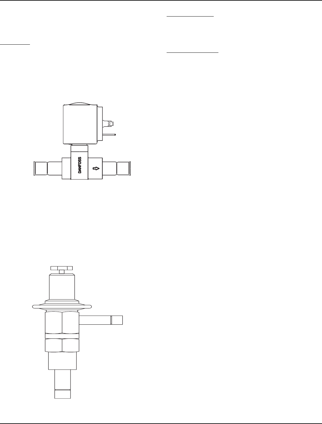
Section 7 Refrigeration System
Part Number 80-1480-3 7-25
HARVEST PRESSURE REGULATING
(H.P.R.) SYSTEM
Remotes Only
GENERAL
The harvest pressure regulating (H.P.R.) system
includes:
• Harvest pressure regulating solenoid valve (H.P.R.
solenoid). This is an electrically operated valve which
opens when energized, and closes when de-
energized.
Figure 7-11. H.P.R. Solenoid
• Harvest pressure regulating valve (H.P.R. valve).
This is a non-adjustable pressure regulating valve
which modulates open and closed, based on the
refrigerant pressure at the outlet of the valve. The
valve closes completely and stops refrigerant flow
when the pressure at the outlet rises above the valve
setting.
Figure 7-12. H.P.R. Valve
FREEZE CYCLE
The H.P.R. system is not used during the freeze cycle.
The H.P.R. solenoid is closed (de-energized), preventing
refrigerant flow into the H.P.R. valve.
HARVEST CYCLE
During the harvest cycle, the check valve in the
discharge line prevents refrigerant in the remote
condenser and receiver from backfeeding into the
evaporator and condensing to liquid.
The H.P.R. solenoid is opened (energized) during the
harvest cycle, allowing refrigerant gas from the top of the
receiver to flow into the H.P.R. valve. The H.P.R. valve
modulates open and closed, raising the suction pressure
high enough to sustain heat for the harvest cycle,
without allowing refrigerant to condense to liquid in the
evaporator.
In general, harvest cycle suction pressure rises, then
stabilizes in the range of 75-100 psig (517-758 kPA).
Exact pressures vary from model to model. These can
be found in the “Operational Refrigerant Pressures”
charts.
SV1427
INLET OUTLET
FLOW
SV3053
OUTLET
INLET

Refrigeration System Section 7
7-26 Part Number 80-1480-3
HPR DIAGNOSTICS
Steps 1 through 4 can be quickly verified without
attaching a manifold gauge set or thermometer.
All questions must have a yes answer to continue
the diagnostic procedure.
1. Liquid line warm?
(Body temperature is normal)
If liquid line is warmer or cooler than body
temperature, refer to headmaster diagnostics.
2. Ice fill pattern normal?
Refer to “Ice Formation Pattern” if ice fill is not
normal.
3. Freeze time normal?
(Refer to Cycle Times/Refrigerant Pressures/24
Hour Ice Production Charts)
Shorter freeze cycles - Refer to headmaster
diagnostics.
Longer freeze cycles - Refer to water system
checklist, then refer to Refrigeration Diagnostic
Procedures.
4. Harvest time is longer than normal and control board
indicates safety limit #2?
(Refer to Cycle Times/Refrigerant Pressures/24
Hour Ice Production Charts)
Connect refrigeration manifold gauge set to the
access valves on the front of the ice machine, and a
thermometer thermocouple on the discharge line
within 6" of the compressor (insulate thermocouple).
Establish baseline by recording suction and
discharge pressure, discharge line temperature and
freeze & harvest cycle times. (Refer to section 7
“Operational Analysis” for data collection detail).
5. Freeze cycle Head Pressure 220 psig (1517 kPa) or
higher?
If the head pressure is lower than 220 psig
(1517 kPa) refer to headmaster diagnostics.
6. Freeze cycle Suction Pressure normal?
Refer to analyzing suction pressure if suction
pressure is high or low.
7. Harvest cycle suction and discharge pressures are
lower than indicated in the cycle times/refrigerant
pressures/24 hour ice production chart?
Replace Harvest Pressure Regulating system (HPR
Valve and HPR solenoid valve).

Section 7 Refrigeration System
Part Number 80-1480-3 7-27
HEADMASTER CONTROL VALVE
Manitowoc remote systems require headmaster control
valves with special settings. Replace defective
headmaster control valves only with “original” Manitowoc
replacement parts.
Operation
The R404A headmaster control valve is non adjustable.
At ambient temperatures of approximately 70°F (21.1°C)
or above, refrigerant flows through the valve from the
condenser to the receiver inlet. At temperatures below
this (or at higher temperatures if it is raining), the head
pressure control dome’s nitrogen charge closes the
condenser port and opens the bypass port from the
compressor discharge line.
In this modulating mode, the valve maintains minimum
head pressure by building up liquid in the condenser and
bypassing discharge gas directly to the receiver.
Diagnosing
1. Determine the air temperature entering the remote
condenser.
2. Determine if the head pressure is high or low in
relationship to the outside temperature. (Refer to the
proper “Operational Pressure Chart” later in this
section.)
3. Determine the temperature of the liquid line entering
the receiver by feeling it. This line is normally warm;
“body temperature.”
4. Using the information gathered, refer to the chart
below.
NOTE: A headmaster that will not bypass, will function
properly with condenser air temperatures of
approximately 70°F (21.1°C) or above. When the
temperature drops below 70°F (21.1°C), the headmaster
fails to bypass and the ice machine malfunctions. Lower
ambient conditions can be simulated by rinsing the
condenser with cool water during the freeze cycle.
Symptom Probable Cause Corrective Measure
Valve not maintaining pressures Non-approved valve Install a Manitowoc Headmaster control
valve with proper setting
Discharge pressure extremely high;
Liquid line entering receiver feels hot Valve stuck in bypass Replace valve
Discharge pressure low; Liquid line
entering receiver feels extremely cold Valve not bypassing Replace valve
Discharge pressure low; Liquid line
entering receiver feels warm to hot
Ice machine has safety limit #1 on cold
mornings.
Ice machine low on charge Locate and repair refrigerant leak.

Refrigeration System Section 7
7-28 Part Number 80-1480-3
FAN CYCLE CONTROL VS. HEADMASTER
A fan cycle control cannot be used in place of a
headmaster. The fan cycle control is not capable of
bypassing the condenser coil and keeping the liquid line
temperature and pressure up.
This is very apparent when it rains or the outside
temperature drops. When it rains or the outside
temperature drops, the fan begins to cycle on and off. At
first, everything appears normal. But, as it continues
raining or getting colder, the fan cycle control can only
turn the fan off. All the refrigerant must continue to flow
through the condenser coil, being cooled by the rain or
low outside temperature.
This causes excessive sub-cooling of the refrigerant. As
a result, the liquid line temperature and pressure are not
maintained for proper operation.
Section 7 Refrigeration System
Part Number 80-1480-3 7-29
Pressure Control Specifications and
Diagnostics
FAN CYCLE CONTROL
(Self-Contained Air-Cooled Models Only)
Function
Cycles the fan motor on and off to maintain proper
operating discharge pressure.
The fan cycle control closes on an increase, and opens
on a decrease in discharge pressure.
Specifications
Check Procedure
1. Verify fan motor windings are not open or grounded,
and fan spins freely.
2. Connect manifold gauges to ice machine.
3. Hook voltmeter in parallel across the fan cycle
control, leaving wires attached.
4. Refer to chart below.
HIGH PRESSURE CUT-OUT (HPCO) CONTROL
Function
Stops the ice machine if subjected to excessive high-
side pressure.
The HPCO control is normally closed, and opens on a
rise in discharge pressure.
Specifications
Cut-out: 450 psig ±10 (3103 kPa ±69, 31 Bar ±.69)
Cut-in: Manual or automatic reset
Must be below 300 psig (2068 kPa, 20.68
Bar ±.69) to reset
Check Procedure
1. Set ICE/OFF/CLEAN switch to OFF.
2. Connect manifold gauges.
3. Hook voltmeter in parallel across the HPCO, leaving
wires attached.
4. On water-cooled models, close the water service
valve to the water condenser inlet. On self-contained
air-cooled and remote models, disconnect the fan
motor.
5. Set ICE/OFF/CLEAN switch to ICE.
6. No water or air flowing through the condenser will
cause the HPCO control to open because of
excessive pressure. Watch the pressure gauge and
record the cut-out pressure.
Replace the HPCO control if it:
• Will not reset [below 300 psig (2068 kPa, 20.68 Bar )]
• Does not open at the specified cut-out point
Model Cut-In (Close) Cut-Out (Open)
S300 / S320
S420 / S450
S500 / S600
S850
250 psig ±5
1723 kPa ±34
17.23 Bar ±.34
200 psig ±5
1517 kPa ±34
1517 Bar ±.34
S1000 / S1200
S1400 / S1600
S1800
275 psig ±5
1896 kPa ±34
18.96 Bar ±.34
225 psig ±5
1551 kPa ±34
15.51 Bar ±.34
At: Reading Should Be: Fan Should Be:
above cut-in 0 volts running
below cut-out line voltage off
!
Warning
If discharge pressure exceeds 460 psig (2068 kPa,
20.68 Bar ) and the HPCO control does not cut out,
set ICE/OFF/CLEAN switch to OFF to stop ice
machine operation.

Refrigeration System Section 7
7-30 Part Number 80-1480-3
Cycle Time/24 Hour Ice Production/
Refrigerant Pressure Charts
These charts are used as guidelines to verify correct ice
machine operation.
Accurate collection of data is essential to obtain the
correct diagnosis.
• Refer to “OPERATIONAL ANALYSIS TABLE” for the
list of data that must be collected for refrigeration
diagnostics. This list includes: before beginning
service, ice production check, installation/visual
inspection, water system checklist, ice formation
pattern, safety limits, comparing evaporator inlet/
outlet temperatures, discharge and suction pressure
analysis.
• Ice production checks that are within 10% of the
chart are considered normal. This is due to variances
in water and air temperature. Actual temperatures
will seldom match the chart exactly.
• Zero out manifold gauge set before obtaining
pressure readings to avoid misdiagnosis.
• Discharge and suction pressure are highest at the
beginning of the cycle. Suction pressure will drop
throughout the cycle. Verify the pressures are within
the range indicated.
• Record beginning of freeze cycle suction pressure
one minute after water pump energizes.
• Regular cube production derate is 7%
• 50Hz production derate is 7%
• 50Hz regular cube total production derate is 14%
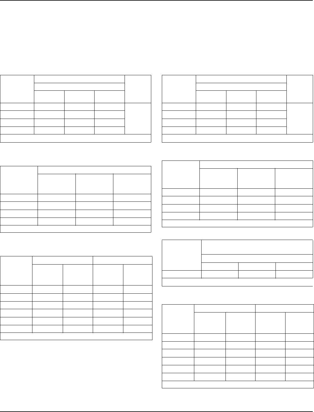
Section 7 Refrigeration System
Part Number 80-1480-3 7-31
S300 SERIES
Self-Contained Air-Cooled
NOTE: These characteristics may vary depending on
operating conditions.
Cycle Times
Freeze Time + Harvest Time = Total Cycle Time
24 Hour Ice Production
Operating Pressures
S300 SERIES
Self-Contained Water-Cooled
NOTE: These characteristics may vary depending on
operating conditions.
Cycle Times
Freeze Time + Harvest Time = Total Cycle Time
24 Hour Ice Production
Operating Pressures
Air Temp.
Entering
Condenser
°F/°C
Freeze Time Harvest
Time
Water Temperature °F/°C
50/10.0 70/21.1 90/32.2
70/21.1 9.3-11.0 10.4-12.2 11.5-13.5
1-2.5
80/26.7 10.0-11.8 11.3-13.2 12.6-14.7
90/32.2 10.8-12.7 12.3-14.4 13.5-15.7
100/37.8 12.3-14.4 13.5-15.7 14.8-17.3
Times in minutes
Air Temp.
Entering
Condenser
°F/°C
Water Temperature °F/°C
50/10.0 70/21.1 90/32.2
70/21.1 325 295 270
80/26.7 305 275 250
90/32.2 285 255 235
100/37.8 255 235 215
Based on average ice slab weight of 2.44 - 2.81 lb
Air Temp.
Entering
Condenser
°F/°C
Freeze Cycle Harvest Cycle
Discharge
Pressure
PSIG
Suction
Pressure
PSIG
Discharge
Pressure
PSIG
Suction
Pressure
PSIG
50/10.0 195-245 50-23 135-160 75-110
70/21.1 195-260 55-24 135-165 80-110
80/26.7 220-290 60-25 150-170 90-120
90/32.2 250-330 70-27 170-195 115-135
100/37.8 285-370 74-28 200-220 130-155
110/43.3 330-415 78-30 230-250 150-175
Suction pressure drops gradually throughout the freeze cycle
Air Temp.
Around Ice
Machine
°F/°C
Freeze Time Harvest
Time
Water Temperature °F/°C
50/10.0 70/21.1 90/32.2
70/21.1 9.8-11.6 10.8-12.7 12.0-14.1
1-2.5
80/26.7 10.0-11.8 11.0-13.0 12.3-14.4
90/32.2 10.4-12.2 11.5-13.5 12.6-14.7
100/37.8 10.6-12.5 11.8-13.8 12.8-15.0
Times in minutes
Air Temp.
Around Ice
Machine
°F/°C
Water Temperature °F/°C
50/10.0 70/21.1 90/32.2
70/21.1 310 285 260
80/26.7 305 280 255
90/32.2 295 270 250
100/37.8 290 265 245
Based on average ice slab weight of 2.44 - 2.81lb
Condenser
Water
Consumption
90/32.2 Air Temperature
Around Ice Machine
Water Temperature °F/°C
59/15.0 70/21.1 90/32.2
Gal/24 hours 250 485 2100
Water regulating valve set to maintain 230 PSIG discharge pressure
Air Temp.
Around Ice
Machine
°F/°C
Freeze Cycle Harvest Cycle
Discharge
Pressure
PSIG
Suction
Pressure
PSIG
Discharge
Pressure
PSIG
Suction
Pressure
PSIG
50/10.0 235-245 50-24 140-180 75-100
70/21.1 235-245 60-25 160-190 90-120
80/26.7 235-265 65-27 160-190 100-130
90/32.2 230-275 65-27 160-190 100-135
100/37.8 230-275 65-28 160-190 100-140
110/43.3 230-275 65-28 170-200 100-140
Suction pressure drops gradually throughout the freeze cycle

Refrigeration System Section 7
7-32 Part Number 80-1480-3
S320 SERIES
Self-Contained Air-Cooled
NOTE: These characteristics may vary depending on
operating conditions.
Cycle Times
Freeze Time + Harvest Time = Total Cycle Time
24 Hour Ice Production
Operating Pressures
S320 SERIES
Self-Contained Water-Cooled
NOTE: These characteristics may vary depending on
operating conditions.
Cycle Times
Freeze Time + Harvest Time = Total Cycle Time
24 Hour Ice Production
Operating Pressures
Air Temp.
Entering
Condenser
°F/°C
Freeze Time Harvest
Time
Water Temperature °F/°C
50/10.0 70/21.1 90/32.2
70/21.1 12.3-14.0 13.1-14.9 14.1-16.0
1-2.5
80/26.7 13.1-14.9 14.6-16.6 15.8-18.0
90/32.2 15.2-17.3 17.2-19.5 18.0-20.4
100/37.8 18.0-20.4 19.8-22.4 20.8-23.5
Times in minutes
Air Temp.
Entering
Condenser
°F/°C
Water Temperature °F/°C
50/10.0 70/21.1 90/32.2
70/21.1 340 320 300
80/26.7 320 290 270
90/32.2 280 250 240
100/37.8 240 220 210
Based on average ice slab weight of 3.25 - 3.65 lb
Air Temp.
Entering
Condenser
°F/°C
Freeze Cycle Harvest Cycle
Discharge
Pressure
PSIG
Suction
Pressure
PSIG
Discharge
Pressure
PSIG
Suction
Pressure
PSIG
50/10.0 195-260 60-34 130-160 80-115
70/21.1 195-260 70-36 130-165 90-120
80/26.7 215-295 75-36 140-165 110-125
90/32.2 240-320 80-38 155-180 120-135
100/37.8 290-365 90-40 175-215 14-165
110/43.3 325-415 95-42 200-230 160-185
Suction pressure drops gradually throughout the freeze cycle
Air Temp.
Around Ice
Machine
°F/°C
Freeze Time Harvest
Time
Water Temperature °F/°C
50/10.0 70/21.1 90/32.2
70/21.1 12.7-14.4 13.6-15.5 15.2-17.3
1-2.5
80/26.7 13.1-14.9 14.1-16.0 15.2-17.3
90/32.2 13.6-15.5 14.6-16.6 15.8-18.0
100/37.8 14.1-16.0 15.2-17.3 16.5-18.7
Times in minutes
Air Temp.
Around Ice
Machine
°F/°C
Water Temperature °F/°C
50/10.0 70/21.1 90/32.2
70/21.1 330 310 280
80/26.7 320 300 280
90/32.2 310 290 270
100/37.8 300 280 260
Based on average ice slab weight of 3.25 - 3.65 lb
Condenser
Water
Consumption
90/32.2 Air Temperature
Around Ice Machine
Water Temperature °F/°C
59/15.0 70/21.1 90/32.2
Gal / per
100 lbs of ice 90 160 1010
Water regulating valve set to maintain 230 PSIG discharge pressure
Air Temp.
Around Ice
Machine
°F/°C
Freeze Cycle Harvest Cycle
Discharge
Pressure
PSIG
Suction
Pressure
PSIG
Discharge
Pressure
PSIG
Suction
Pressure
PSIG
50/10.0 225-245 60-38 150-185 85-105
70/21.1 225-245 68-38 150-190 100-120
80/26.7 225-250 78-39 155-195 110-145
90/32.2 225-255 80-40 155-200 115-145
100/37.8 225-260 82-41 155-205 120-150
110/43.3 225-265 85-42 155-210 120-150
Suction pressure drops gradually throughout the freeze cycle

Section 7 Refrigeration System
Part Number 80-1480-3 7-33
S420 SERIES
Self-Contained Air-Cooled
NOTE: These characteristics may vary depending on
operating conditions.
Cycle Times
Freeze Time + Harvest Time = Total Cycle Time
24 Hour Ice Production
Operating Pressures
S420 SERIES
Self-Contained Water-Cooled
NOTE: These characteristics may vary depending on
operating conditions.
Cycle Times
Freeze Time + Harvest Time = Total Cycle Time
24 Hour Ice Production
Operating Pressures
Air Temp.
Entering
Condenser
°F/°C
Freeze Time Harvest
Time
Water Temperature °F/°C
50/10.0 70/21.1 90/32.2
70/21.1 9.4-10.0 10.2-10.8 11.1-11.8
1-2.580/26.7 9.9-10.6 10.7-11.5 11.7-12.5
90/32.2 10.4-11.1 11.4-12.1 12.5-13.3
Times in minutes
Air Temp.
Entering
Condenser
°F/°C
Water Temperature °F/°C
50/10.0 70/21.1 90/32.2
70/21.1 450 420 390
80/26.7 430 400 370
90/32.2 410 380 350
Based on average ice slab weight of 3.40 - 3.60 lb
Air Temp.
Entering
Condenser
°F/°C
Freeze Cycle Harvest Cycle
Discharge
Pressure
PSIG
Suction
Pressure
PSIG
Discharge
Pressure
PSIG
Suction
Pressure
PSIG
50/10.0 195-255 50-30 125-150 70-90
70/21.1 195-270 60-30 135-190 80-115
80/26.7 220-285 62-32 135-195 80-115
90/32.2 250-320 70-34 175-195 85-115
100/37.8 290-390 75-35 190-215 115-140
110/43.3 320-400 80-37 225-250 130-170
Suction pressure drops gradually throughout the freeze cycle
Air Temp.
Around Ice
Machine
°F/°C
Freeze Time Harvest
Time
Water Temperature °F/°C
50/10.0 70/21.1 90/32.2
70/21.1 8.9-9.5 9.6-10.3 10.7-11.5
1-2.580/26.7 9.1-9.8 9.9-10.6 11.1-11.8
90/32.2 9.4-10.0 10.2-10.8 11.4-12.1
Times in minutes
Air Temp.
Around Ice
Machine
°F/°C
Water Temperature °F/°C
50/10.0 70/21.1 90/32.2
70/21.1 470 440 400
80/26.7 460 430 390
90/32.2 450 420 380
Based on average ice slab weight of 3.40 - 3.60 lb
Condenser
Water
Consumption
90/32.2 Air Temperature
Around Ice Machine
Water Temperature °F/°C
59/15.0 70/21.1 90/32.2
Gal / per
100 lbs of ice NA 200 NA
Water regulating valve set to maintain 240 PSIG discharge pressure
Air Temp.
Around Ice
Machine
°F/°C
Freeze Cycle Harvest Cycle
Discharge
Pressure
PSIG
Suction
Pressure
PSIG
Discharge
Pressure
PSIG
Suction
Pressure
PSIG
70/21.1 225-265 52-30 160-190 85-100
80/26.7 230-265 56-30 170-190 90-110
90/32.2 230-270 62-31 170-195 95-115
100/37.8 235-275 65-31 170-200 100-120
110/43.3 240-280 65-32 170-205 100-120
Suction pressure drops gradually throughout the freeze cycle
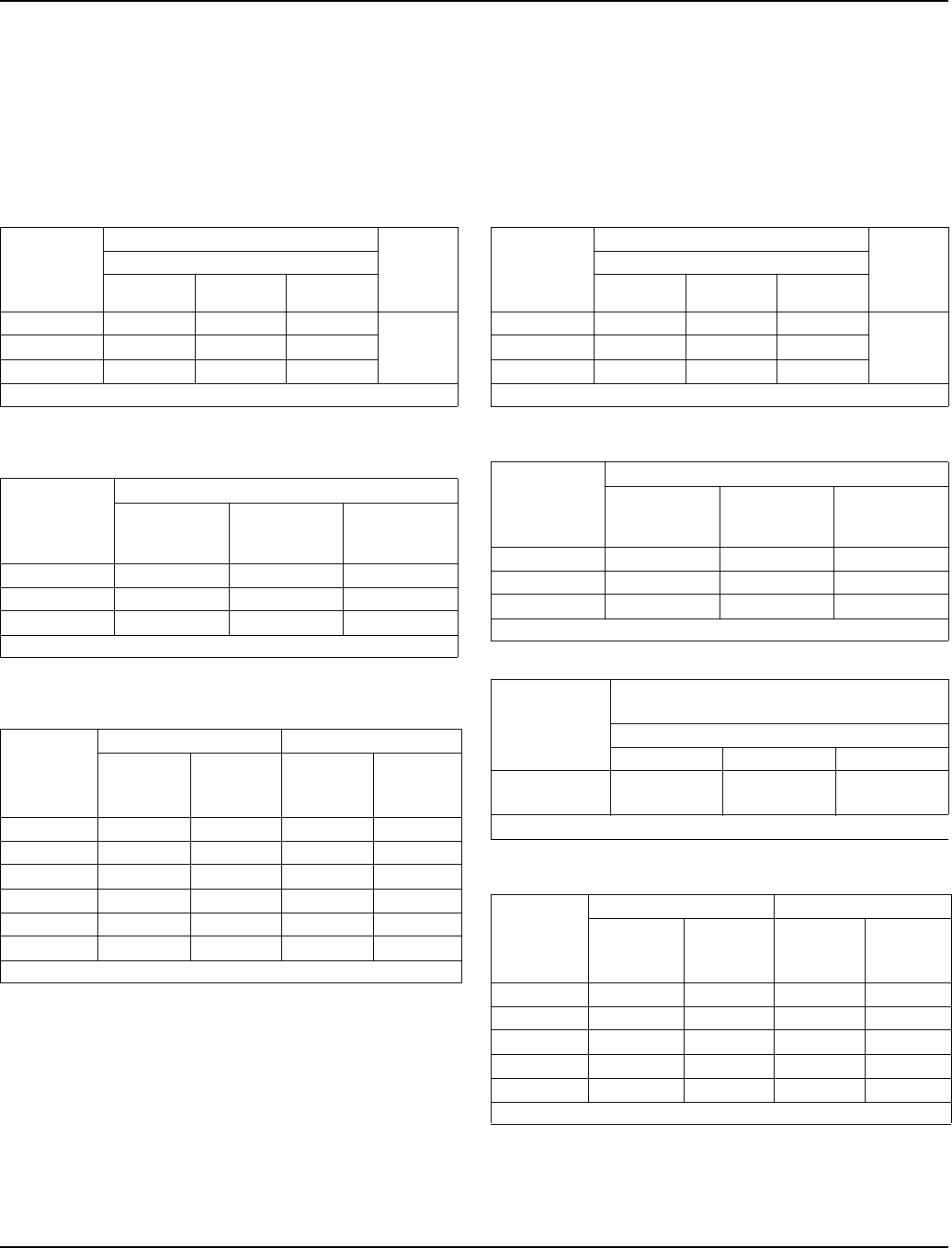
Refrigeration System Section 7
7-34 Part Number 80-1480-3
S450 SERIES
Self-Contained Air-Cooled
NOTE: These characteristics may vary depending on
operating conditions.
Cycle Times
Freeze Time + Harvest Time = Total Cycle Time
24 Hour Ice Production
Operating Pressures
S450 SERIES
Self-Contained Water-Cooled
NOTE: These characteristics may vary depending on
operating conditions.
Cycle Times
Freeze Time + Harvest Time = Total Cycle Time
24 Hour Ice Production
Operating Pressures
Air Temp.
Entering
Condenser
°F/°C
Freeze Time Harvest
Time
Water Temperature °F/°C
50/10.0 70/21.1 90/32.2
70/21.1 9.4-10.0 10.2-10.8 11.1-11.8
1-2.580/26.7 9.9-10.6 10.7-11.5 11.7-12.5
90/32.2 10.4-11.1 11.4-12.1 12.5-13.3
Times in minutes
Air Temp.
Entering
Condenser
°F/°C
Water Temperature °F/°C
50/10.0 70/21.1 90/32.2
70/21.1 450 420 390
80/26.7 430 400 370
90/32.2 410 380 350
Based on average ice slab weight of 3.40 - 3.60 lb
Air Temp.
Entering
Condenser
°F/°C
Freeze Cycle Harvest Cycle
Discharge
Pressure
PSIG
Suction
Pressure
PSIG
Discharge
Pressure
PSIG
Suction
Pressure
PSIG
50/10.0 195-255 50-30 125-150 70-90
70/21.1 195-270 60-30 135-190 80-115
80/26.7 220-285 62-32 135-195 80-115
90/32.2 250-320 70-34 175-195 85-115
100/37.8 290-390 75-35 190-215 115-140
110/43.3 320-400 80-37 225-250 130-170
Suction pressure drops gradually throughout the freeze cycle
Air Temp.
Around Ice
Machine
°F/°C
Freeze Time Harvest
Time
Water Temperature °F/°C
50/10.0 70/21.1 90/32.2
70/21.1 8.9-9.5 9.6-10.3 10.7-11.5
1-2.580/26.7 9.1-9.8 9.9-10.6 11.1-11.8
90/32.2 9.4-10.0 10.2-10.8 11.4-12.1
Times in minutes
Air Temp.
Around Ice
Machine
°F/°C
Water Temperature °F/°C
50/10.0 70/21.1 90/32.2
70/21.1 470 440 400
80/26.7 460 430 390
90/32.2 450 420 380
Based on average ice slab weight of 3.40 - 3.60 lb
Condenser
Water
Consumption
90/32.2 Air Temperature
Around Ice Machine
Water Temperature °F/°C
59/15.0 70/21.1 90/32.2
Gal / per
100 lbs of ice NA 200 NA
Water regulating valve set to maintain 240 PSIG discharge pressure
Air Temp.
Around Ice
Machine
°F/°C
Freeze Cycle Harvest Cycle
Discharge
Pressure
PSIG
Suction
Pressure
PSIG
Discharge
Pressure
PSIG
Suction
Pressure
PSIG
70/21.1 225-265 52-30 160-190 85-100
80/26.7 230-265 56-30 170-190 90-110
90/32.2 230-270 62-31 170-195 95-115
100/37.8 235-275 65-31 170-200 100-120
110/43.3 240-280 65-32 170-205 100-120
Suction pressure drops gradually throughout the freeze cycle
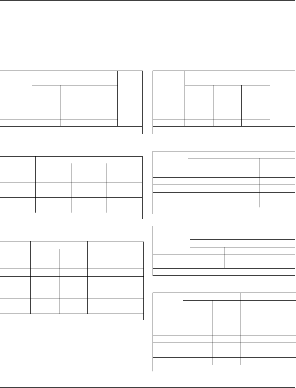
Section 7 Refrigeration System
Part Number 80-1480-3 7-35
S500 SERIES
Self-Contained Air-Cooled
NOTE: These characteristics may vary depending on
operating conditions.
Cycle Times
Freeze Time + Harvest Time = Total Cycle Time
24 Hour Ice Production
Operating Pressures
S500 SERIES
Self-Contained Water-Cooled
NOTE: These characteristics may vary depending on
operating conditions.
Cycle Times
Freeze Time + Harvest Time = Total Cycle Time
24 Hour Ice Production
Operating Pressures
Air Temp.
Entering
Condenser
°F/°C
Freeze Time Harvest
Time
Water Temperature °F/°C
50/10.0 70/21.1 90/32.2
70/21.1 9.5-11.2 11.1-13.1 12.0-14.0
1-2.5
80/26.7 10.4-12.2 12.3-14.4 12.6-14.8
90/32.2 11.4-13.4 13.3-15.6 14.1-16.5
100/37.8 13.7-16.0 15.0-17.5 15.9-18.6
Times in minutes
Air Temp.
Entering
Condenser
°F/°C
Water Temperature °F/°C
50/10.0 70/21.1 90/32.2
70/21.1 540 470 440
80/26.7 500 430 420
90/32.2 460 400 380
100/37.8 390 360 340
Based on average ice slab weight of 4.12 - 4.75 lb
Air Temp.
Entering
Condenser
°F/°C
Freeze Cycle Harvest Cycle
Discharge
Pressure
PSIG
Suction
Pressure
PSIG
Discharge
Pressure
PSIG
Suction
Pressure
PSIG
50/10.0 200-255 44-26 130-160 75-90
70/21.1 200-255 47-28 135-160 80-95
80/26.7 220-295 50-29 160-175 90-105
90/32.2 250-325 55-31 175-205 105-120
100/37.8 270-370 60-32 200-225 120-145
110/43.3 290-425 75-36 220-260 150-165
Suction pressure drops gradually throughout the freeze cycle
Air Temp.
Around Ice
Machine
°F/°C
Freeze Time Harvest
Time
Water Temperature °F/°C
50/10.0 70/21.1 90/32.2
70/21.1 9.3-10.9 10.6-12.5 12.0-14.0
1-2.5
80/26.7 9.7-11.4 10.9-12.8 12.3-14.4
90/32.2 9.9-11.7 10.9-12.8 12.6-14.8
100/37.8 10.1-11.9 11.4-13.4 13.0-15.2
Times in minutes
Air Temp.
Around Ice
Machine
°F/°C
Water Temperature °F/°C
50/10.0 70/21.1 90/32.2
70/21.1 550 490 440
80/26.7 530 480 430
90/32.2 520 480 420
100/37.8 510 460 410
Based on average ice slab weight of 4.12 - 4.75lb
Condenser
Water
Consumption
90/32.2 Air Temperature
Around Ice Machine
Water Temperature °F/°C
59/15.0 70/21.1 90/32.2
Gal / per
100 lbs of ice 87 138 458
Water regulating valve set to maintain 230 PSIG discharge pressure
Air Temp.
Around Ice
Machine
°F/°C
Freeze Cycle Harvest Cycle
Discharge
Pressure
PSIG
Suction
Pressure
PSIG
Discharge
Pressure
PSIG
Suction
Pressure
PSIG
50/10.0 225-235 45-30 160-180 80-115
70/21.1 225-260 45-30 165-195 90-120
80/26.7 225-265 46-31 165-195 95-120
90/32.2 230-265 46-32 165-195 95-120
100/37.8 230-270 48-32 165-200 100-125
110/43.3 235-270 50-32 165-205 105-125
Suction pressure drops gradually throughout the freeze cycle
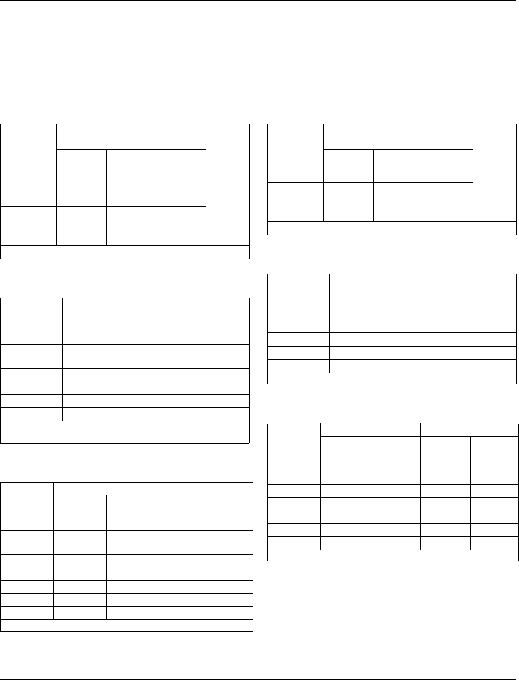
Refrigeration System Section 7
7-36 Part Number 80-1480-3
S500 SERIES
Remote
NOTE: These characteristics may vary depending on
operating conditions.
Cycle Times
Freeze Time + Harvest Time = Total Cycle Time
24 Hour Ice Production
Operating Pressures
S600 SERIES
Self-Contained Air-Cooled
NOTE: These characteristics may vary depending on
operating conditions.
Cycle Times
Freeze Time + Harvest Time = Total Cycle Time
24 Hour Ice Production
Operating Pressures
Air Temp.
Entering
Condenser
°F/°C
Freeze Time Harvest
Time
Water Temperature °F/°C
50/10.0 70/21.1 90/32.2
-20/-28.9 to
70/21.1 9.9-11.7 11.1-13.1 12.6-14.8
1-2.5
80/26.7 9.9-11.7 11.4-13.4 12.6-14.8
90/32.2 10.1-11.9 11.4-13.4 12.6-14.8
100/37.8 10.9-12.8 12.3-14.4 13.3-15.6
110/43.3 12.0-14.0 13.3-15.6 14.1-16.5
Times in minutes
Air Temp.
Entering
Condenser
°F/°C
Water Temperature °F/°C
50/10.0 70/21.1 90/32.2
-20/-28.9 to
70/21.1 520 470 420
80/26.7 520 460 420
90/32.2 510 460 420
100/37.8 480 430 400
110/43.3 440 400 380
Based on average ice slab weight of 4.12 - 4.75 lb
Ratings with JC495 condenser, dice or half dice cubes
Air Temp.
Entering
Condenser
°F/°C
Freeze Cycle Harvest Cycle
Discharge
Pressure
PSIG
Suction
Pressure
PSIG
Discharge
Pressure
PSIG
Suction
Pressure
PSIG
-20/-28.9 to
50/10.0 210-240 42-29 105-160 75-100
70/21.1 235-250 48-31 105-165 85-100
80/26.7 245-260 50-32 110-165 85-100
90/32.2 250-270 52-33 110-170 90-105
100/37.8 265-315 60-34 125-175 90-110
110/43.3 295-365 62-35 130-185 95-115
Suction pressure drops gradually throughout the freeze cycle
Air Temp.
Entering
Condenser
°F/°C
Freeze Time Harvest
Time
Water Temperature °F/°C
50/10.0 70/21.1 90/32.2
70/21.1 7.6-9.0 8.4-9.9 9.1-10.7
1-2.5
80/26.7 7.8-9.2 8.8-10.3 9.3-10.9
90/32.2 8.6-10.1 9.5-11.2 10.2-11.9
100/37.8 9.9-11.7 10.9-12.8 11.4-13.4
Times in minutes
Air Temp.
Entering
Condenser
°F/°C
Water Temperature °F/°C
50/10.0 70/21.1 90/32.2
70/21.1 650 600 560
80/26.7 640 580 550
90/32.2 590 540 510
100/37.8 520 480 460
Based on average ice slab weight of 4.12 - 4.75 lb
Air Temp.
Entering
Condenser
°F/°C
Freeze Cycle Harvest Cycle
Discharge
Pressure
PSIG
Suction
Pressure
PSIG
Discharge
Pressure
PSIG
Suction
Pressure
PSIG
50/10.0 220-255 45-27 140-160 60-80
70/21.1 220-270 45-28 145-170 70-90
80/26.7 230-300 50-30 165-185 75-95
90/32.2 265-345 54-32 180-215 80-105
100/37.8 300-395 60-35 210-245 85-120
110/43.3 340-430 65-39 240-280 100-140
Suction pressure drops gradually throughout the freeze cycle
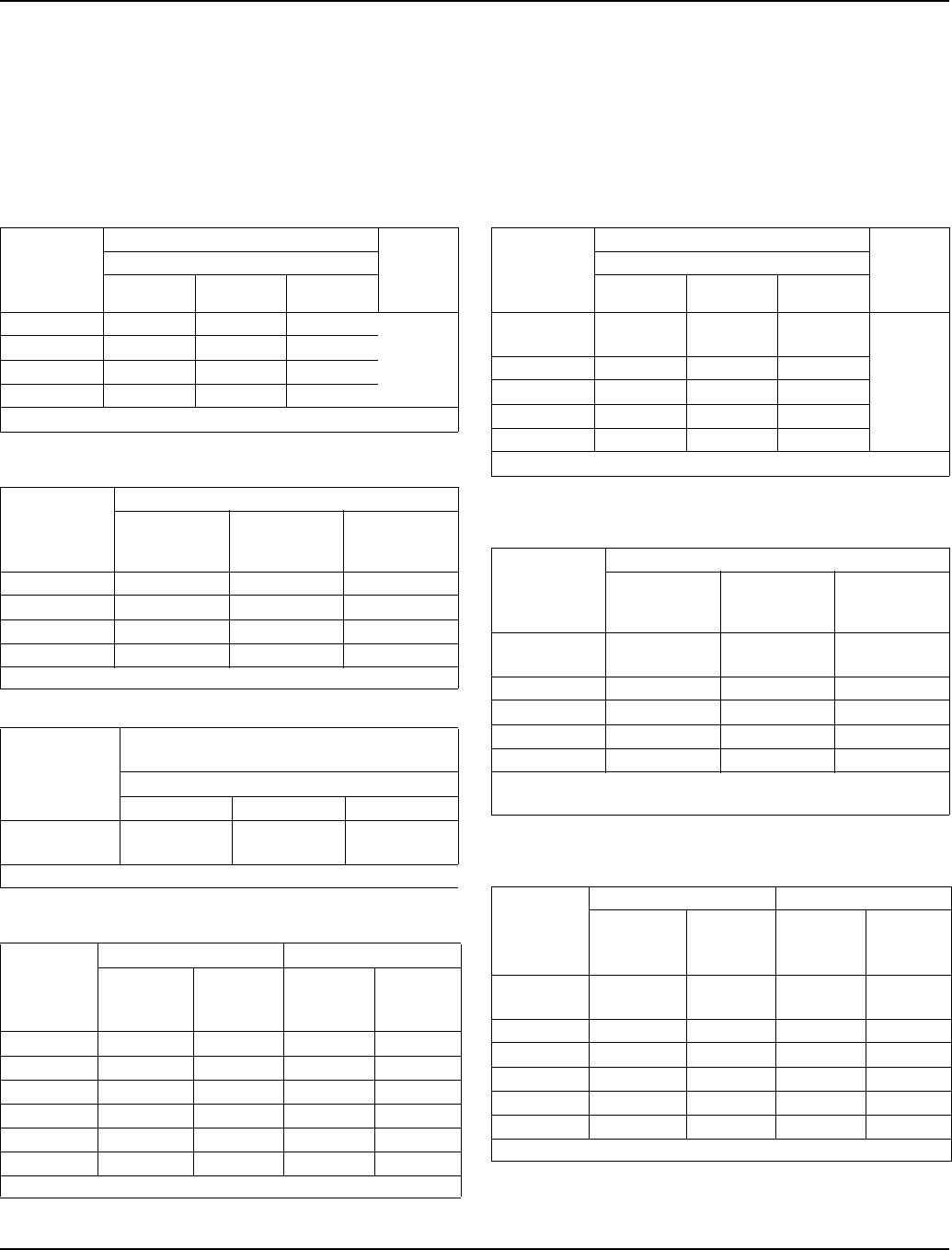
Section 7 Refrigeration System
Part Number 80-1480-3 7-37
S600 SERIES
Self-Contained Water-Cooled
NOTE: These characteristics may vary depending on
operating conditions.
Cycle Times
Freeze Time + Harvest Time = Total Cycle Time
24 Hour Ice Production
Operating Pressures
S600 SERIES
Remote
NOTE: These characteristics may vary depending on
operating conditions.
Cycle Times
Freeze Time + Harvest Time = Total Cycle Time
24 Hour Ice Production
Operating Pressures
Air Temp.
Around Ice
Machine
°F/°C
Freeze Time Harvest
Time
Water Temperature °F/°C
50/10.0 70/21.1 90/32.2
70/21.1 7.6-9.0 7.9-9.4 8.6-10.1
1-2.5
80/26.7 7.8-9.2 8.1-9.5 8.8-10.3
90/32.2 7.9-9.4 8.2-9.7 8.8-10.3
100/37.8 8.1-9.5 8.4-9.9 9.1-10.7
Times in minutes
Air Temp.
Around Ice
Machine
°F/°C
Water Temperature °F/°C
50/10.0 70/21.1 90/32.2
70/21.1 650 630 590
80/26.7 640 620 580
90/32.2 630 610 580
100/37.8 620 600 560
Based on average ice slab weight of 4.12 - 4.75lb
Condenser
Water
Consumption
90/32.2 Air Temperature
Around Ice Machine
Water Temperature °F/°C
59/15.0 70/21.1 90/32.2
Gal / per
100 lbs of ice 110 170 870
Water regulating valve set to maintain 2340 PSIG discharge pressure
Air Temp.
Around Ice
Machine
°F/°C
Freeze Cycle Harvest Cycle
Discharge
Pressure
PSIG
Suction
Pressure
PSIG
Discharge
Pressure
PSIG
Suction
Pressure
PSIG
50/10.0 225-235 36-26 140-190 65-95
70/21.1 225-235 36-26 140-190 65-95
80/26.7 225-245 40-28 150-195 70-100
90/32.2 230-255 40-29 160-200 70-100
100/37.8 230-260 40-30 170-205 75-105
110/43.3 230-260 40-30 180-210 80-110
Suction pressure drops gradually throughout the freeze cycle
Air Temp.
Entering
Condenser
°F/°C
Freeze Time Harvest
Time
Water Temperature °F/°C
50/10.0 70/21.1 90/32.2
-20/-28.9 to
70/21.1 7.9-9.4 8.8-10.3 9.3-10.9
1-2.5
80/26.7 7.9-94 8.9-10.5- 9.5-11.2
90/32.2 8.1-9.5 8.9-10.5 9.7-11.4
100/37.8 8.8-10.3 9.7-11.4 10.4-12.2
110/43.3 9.7-11.4 10.6-12.5 11.4-13.4
Times in minutes
Air Temp.
Entering
Condenser
°F/°C
Water Temperature °F/°C
50/10.0 70/21.1 90/32.2
-20/-28.9 to
70/21.1 630 580 550
80/26.7 630 570 530
90/32.2 620 570 540
100/37.8 580 530 500
110/43.3 530 490 460
Based on average ice slab weight of 4.12 - 4.75 lb
Ratings with JC495 condenser, dice or half dice cubes
Air Temp.
Entering
Condenser
°F/°C
Freeze Cycle Harvest Cycle
Discharge
Pressure
PSIG
Suction
Pressure
PSIG
Discharge
Pressure
PSIG
Suction
Pressure
PSIG
-20/-28.9 to
50/10.0 210-240 40-29 130-190 62-80
70/21.1 225-250 50-30 130-200 75-95
80/26.7 245-275 52-31 130-200 75-100
90/32.2 245-285 52-32 135-200 80-100
100/37.8 260-315 55-32 140-200 80-100
110/43.3 290-365 60-34 170-200 85-100
Suction pressure drops gradually throughout the freeze cycle
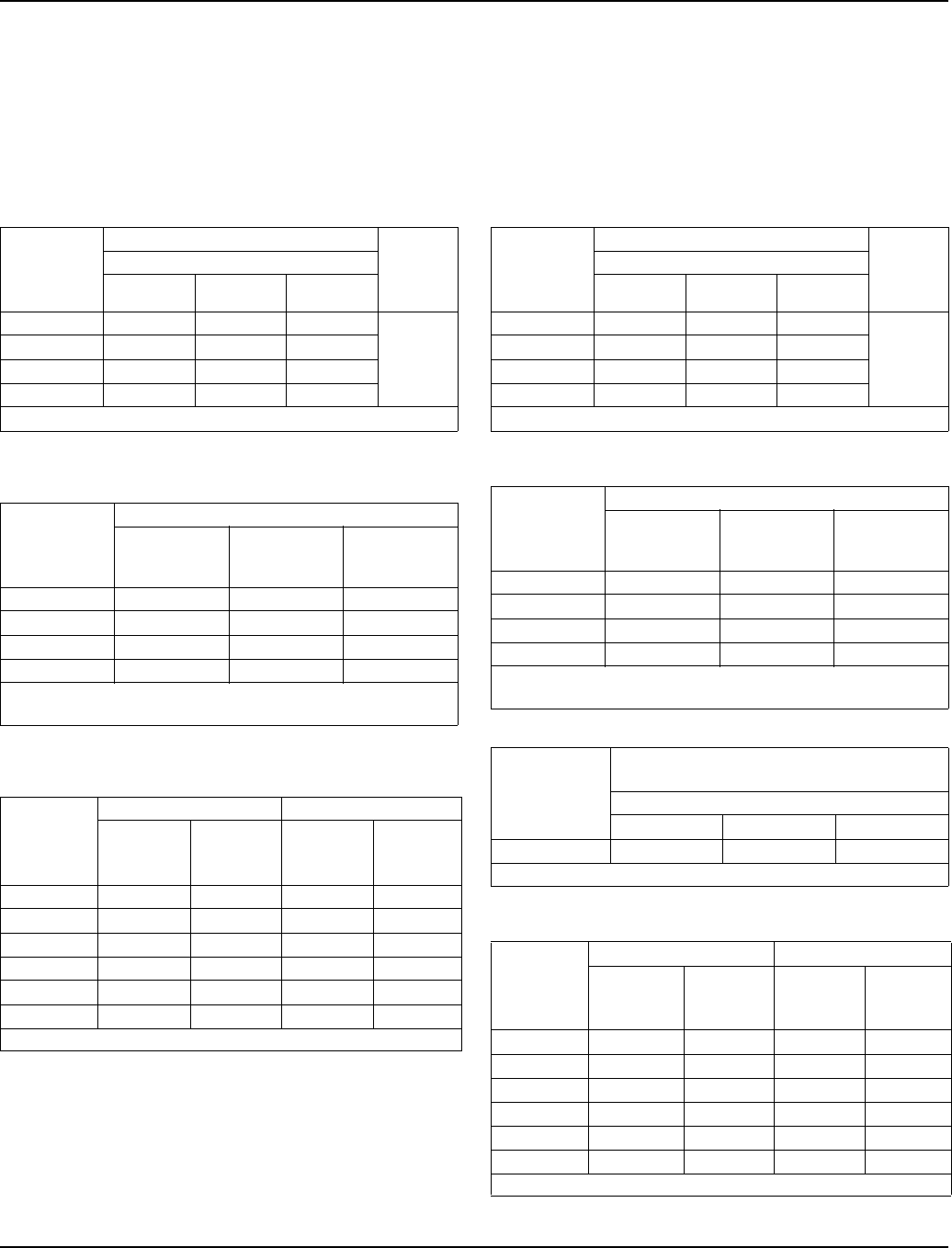
Refrigeration System Section 7
7-38 Part Number 80-1480-3
S850 SERIES
Self-Contained Air-Cooled
NOTE: These characteristics may vary depending on
operating conditions.
Cycle Times
Freeze Time + Harvest Time = Total Cycle Time
24 Hour Ice Production
Operating Pressures
S850 SERIES
Self-Contained Water-Cooled
NOTE: These characteristics may vary depending on
operating conditions.
Cycle Times
Freeze Time + Harvest Time = Total Cycle Time
24 Hour Ice Production
Operating Pressures
Air Temp.
Entering
Condenser
°F/°C
Freeze Time Harvest
Time
Water Temperature °F/°C
50/10.0 70/21.1 90/32.2
70/21.1 8.0-9.3 8.9-10.2 9.3-10.7
1-2.5
80/26.7 8.5-9.8 9.4-10.8 9.8-11.3
90/32.2 9.7-11.1 10.9-12.5 11.4-13.1
100/37.8 10.7-12.3 12.1-13.8 12.8-14.6
Times in minutes
Air Temp.
Entering
Condenser
°F/°C
Water Temperature °F/°C
50/10.0 70/21.1 90/32.2
70/21.1 870 800 770
80/26.7 830 760 730
90/32.2 740 670 640
100/37.8 680 610 580
Based on average ice slab weight of 5.75 - 6.50lb
Regular cube derate is 7%
Air Temp.
Entering
Condenser
°F/°C
Freeze Cycle Harvest Cycle
Discharge
Pressure
PSIG
Suction
Pressure
PSIG
Discharge
Pressure
PSIG
Suction
Pressure
PSIG
50/10.0 200-250 40-28 130-145 70-85
70/21.1 200-250 40-28 130-145 70-85
80/26.7 230-275 50-28 150-165 70-90
90/32.2 260-310 54-32 165-185 85-105
100/37.8 300-355 65-32 180-210 105-125
110/43.3 325-405 70-38 215-235 120-150
Suction pressure drops gradually throughout the freeze cycle
Air Temp.
Around Ice
Machine
°F/°C
Freeze Time Harvest
Time
Water Temperature °F/°C
50/10.0 70/21.1 90/32.2
70/21.1 7.9-9.1 8.7-10.1 9.8-11.3
1-2.5
80/26.7 8.0-9.3 8.9-10.2 10.0-11.5
90/32.2 8.1-9.4 9.0-10.3 10.2-11.7
100/37.8 8.2-9.5 9.1-10.5 10.3-11.9
Times in minutes
Air Temp.
Around Ice
Machine
°F/°C
Water Temperature °F/°C
50/10.0 70/21.1 90/32.2
70/21.1 880 810 730
80/26.7 870 800 720
90/32.2 860 790 710
100/37.8 850 780 700
Based on average ice slab weight of 5.75- 6.50lb
Regular cube derate is 7%
Condenser
Water
Consumption
90/32.2 Air Temperature
Around Ice Machine
Water Temperature °F/°C
50/10.0 70/21.1 90/32.2
Gal/24 hours 690 1420 5200
Water regulating valve set to maintain 240 PSIG discharge pressure
Air Temp.
Around Ice
Machine
°F/°C
Freeze Cycle Harvest Cycle
Discharge
Pressure
PSIG
Suction
Pressure
PSIG
Discharge
Pressure
PSIG
Suction
Pressure
PSIG
50/10.0 225-235 46-28 150-160 75-90
70/21.1 225-235 46-28 150-160 75-90
80/26.7 225-240 50-30 155-175 80-95
90/32.2 230-270 60-30 155-185 85-105
100/37.8 240-275 60-30 165-185 90-110
110/43.3 245-280 60-30 175-190 95-115
Suction pressure drops gradually throughout the freeze cycle
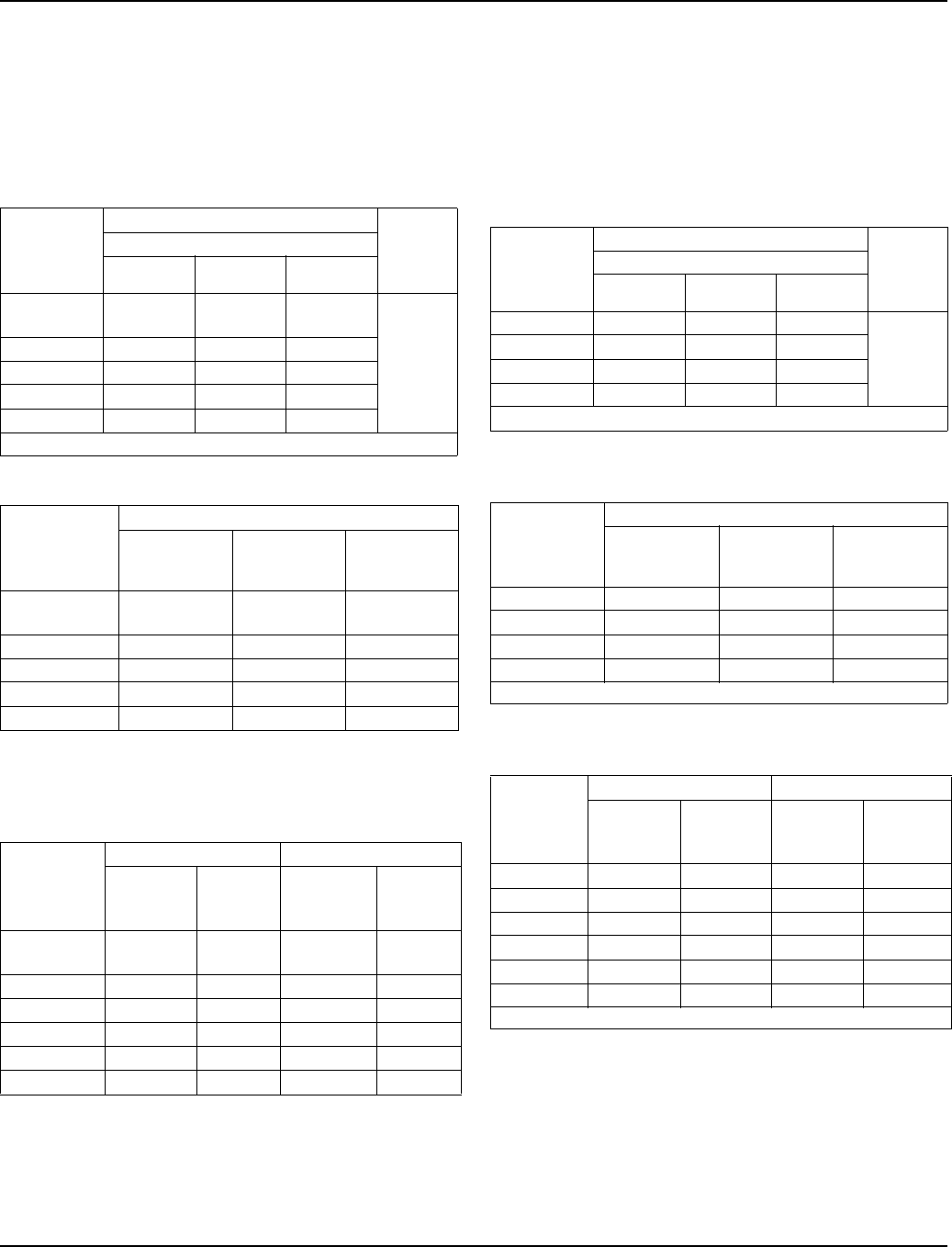
Section 7 Refrigeration System
Part Number 80-1480-3 7-39
S850 SERIES
Remote
NOTE: These characteristics may vary depending on
operating conditions.
Cycle Times
Freeze Time + Harvest Time = Total Cycle Time
24 Hour Ice Production
Operating Pressures
S1000 SERIES
Self-Contained Air-Cooled
NOTE: These characteristics may vary depending on
operating conditions.
Cycle Times
Freeze Time + Harvest Time = Total Cycle Time
24 Hour Ice Production
Operating Pressures
Air Temp.
Entering
Condenser
°F/°C
Freeze Time Harvest
Time
Water Temperature °F/°C
50/10.0 70/21.1 90/32.2
-20/-28.9 to
70/21.1 8.6-9.9 9.1-10.5 9.7-11.1
1-2.5
80/26.7 8.9-10.2 9.5-11.0 10.0-11.5
90/32.2 9.1-10.5 9.8-11.3 11.3-11.9
100/37.8 9.8-11.3 10.7-12.3 11.2-12.9
110/43.3 10.9-12.5 11.9-13.6 12.5-14.4
Times in minutes
Air Temp.
Entering
Condenser
°F/°C
Water Temperature °F/°C
Based on average ice slab weight of 5.75 -6.50 lb
Ratings with JC0895 condenser
Regular cube derate production 7%
50/10.0 70/21.1 90/32.2
-20/-28.9 to
70/21.1 820 780 740
80/26.7 800 750 720
90/32.2 780 730 700
100/37.8 730 680 650
110/43.3 670 620 590
Air Temp.
Entering
Condenser
°F/°C
Freeze Cycle Harvest Cycle
Discharge
Pressure
PSIG
Suction
Pressure
PSIG
Discharge
Pressure
PSIG
Suction
Pressure
PSIG
Suction pressure drops gradually throughout the freeze cycle
-20/-28.9 to
50/10.0 220-250 50-30 100-160 70-90
70/21.1 220-260 50-30 100-160 70-90
80/26.7 240-265 50-30 100-160 75-90
90/32.2 250-280 52-30 100-160 75-95
100/37.8 280-320 52-30 110-165 75-95
110/43.3 310-365 62-31 125-170 80-100
Air Temp.
Entering
Condenser
°F/°C
Freeze Time Harvest
Time
Water Temperature °F/°C
50/10.0 70/21.1 90/32.2
70/21.1 6.3-7.3 6.9-8.0 7.6-8.8
.75-2.0080/26.7 6.9-8.1 7.6-8.8 8.4-9.6
90/32.2 7.8-9.0 8.5-9.8 9.4-10.8
100/37.8 9.3-10.7 10.2-11.7 11.0-12.7
Times in minutes
Air Temp.
Entering
Condenser
°F/°C
Water Temperature °F/°C
50/10.0 70/21.1 90/32.2
70/21.1 1060 990 910
80/26.7 980 910 840
90/32.2 890 830 760
100/37.8 770 710 660
Based on average ice slab weight of 5.75 - 6.50lb
Air Temp.
Entering
Condenser
°F/°C
Freeze Cycle Harvest Cycle
Discharge
Pressure
PSIG
Suction
Pressure
PSIG
Discharge
Pressure
PSIG
Suction
Pressure
PSIG
50/10.0 195-255 50-26 130-145 70-90
70/21.1 220-275 50-26 130-145 70-90
80/26.7 235-290 52-28 150-165 75-95
90/32.2 265-330 58-28 165-185 85-110
100/37.8 300-360 60-31 180-210 95-120
110/43.3 330-415 66-32 215-235 115-145
Suction pressure drops gradually throughout the freeze cycle
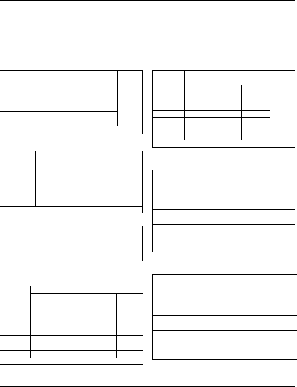
Refrigeration System Section 7
7-40 Part Number 80-1480-3
S1000 SERIES
Self-Contained Water-Cooled
NOTE: These characteristics may vary depending on
operating conditions.
Cycle Times
Freeze Time + Harvest Time = Total Cycle Time
24 Hour Ice Production
Operating Pressures
S1000 SERIES
Remote
NOTE: These characteristics may vary depending on
operating conditions.
Cycle Times
Freeze Time + Harvest Time = Total Cycle Time
24 Hour Ice Production
Operating Pressures
Air Temp.
Around Ice
Machine
°F/°C
Freeze Time Harvest
Time
Water Temperature °F/°C
50/10.0 70/21.1 90/32.2
70/21.1 6.8-7.9 7.4-8.6 8.5-9.8
.75-2.00
80/26.7 6.9-8.0 7.5-8.7 8.6-9.9
90/32.2 6.9-8.1 7.6-8.8 8.7-10.1
100/37.8 7.0-8.1 7.7-8.9 8.9-10.2
Times in minutes
Air Temp.
Around Ice
Machine
°F/°C
Water Temperature °F/°C
50/10.0 70/21.1 90/32.2
70/21.1 1000 930 830
80/26.7 990 920 820
90/32.2 980 910 810
100/37.8 970 900 800
Based on average ice slab weight of 5.75- 6.50lb
Condenser
Water
Consumption
90/32.2 Air Temperature
Around Ice Machine
Water Temperature °F/°C
50/10.0 70/21.1 90/32.2
Gal/24 hours 710 1500 5100
Water regulating valve set to maintain 240 PSIG discharge pressure
Air Temp.
Around Ice
Machine
°F/°C
Freeze Cycle Harvest Cycle
Discharge
Pressure
PSIG
Suction
Pressure
PSIG
Discharge
Pressure
PSIG
Suction
Pressure
PSIG
50/10.0 235-245 40-24 160-175 75-90
70/21.1 235-245 40-25 160-175 75-90
80/26.7 235-250 42-26 170-185 80-95
90/32.2 240-270 48-28 175-205 85-105
100/37.8 250-280 52-28 180-210 90-110
110/43.3 250-285 54-28 185-215 95-115
Suction pressure drops gradually throughout the freeze cycle
Air Temp.
Entering
Condenser
°F/°C
Freeze Time Harvest
Time
Water Temperature °F/°C
50/10.0 70/21.1 90/32.2
-20/-28.9 to
70/21.1 7.1-8.3 7.6-8.8 8.4-9.6
.75-2.00
80/26.7 7.5-8.7 8.0-9.3 8.9-10.2
90/32.2 7.7-8.9 8.2-9.5 9.1-10.5
100/37.8 8.1-9.4 8.7-10.1 9.7-11.1
110/43.3 8.7-10.1 9.4-10.8 10.7-12.3
Times in minutes
Air Temp.
Entering
Condenser
°F/°C
Water Temperature °F/°C
50/10.0 70/21.1 90/32.2
-20/-28.9 to
70/21.1 960 910 840
80/26.7 920 870 800
90/32.2 900 850 780
100/37.8 860 810 740
110/43.3 810 760 680
Based on average ice slab weight of 5.75- 6.50lb
Ratings with JC0895 condenser
Air Temp.
Entering
Condenser
°F/°C
Freeze Cycle Harvest Cycle
Discharge
Pressure
PSIG
Suction
Pressure
PSIG
Discharge
Pressure
PSIG
Suction
Pressure
PSIG
-20/-28.9 to
50/10.0 220-255 40-26 100-170 65-90
70/21.1 245-260 40-27 100-170 65-90
80/26.7 245-285 42-28 100-170 65-95
90/32.2 250-300 44-28 100-175 65-100
100/37.8 275-330 48-29 115-180 65-105
110/43.3 310-375 56-31 125-195 65-105
Suction pressure drops gradually throughout the freeze cycle

Section 7 Refrigeration System
Part Number 80-1480-3 7-41
S1200 SERIES
Self-Contained Air-Cooled
NOTE: These characteristics may vary depending on
operating conditions.
Cycle Times
Freeze Time + Harvest Time = Total Cycle Time
24 Hour Ice Production
Operating Pressures
S1200 SERIES
Self-Contained Water-Cooled
NOTE: These characteristics may vary depending on
operating conditions.
Cycle Times
Freeze Time + Harvest Time = Total Cycle Time
24 Hour Ice Production
Operating Pressures
Air Temp.
Entering
Condenser
°F/°C
Freeze Time Harvest
Time
Water Temperature °F/°C
50/10.0 70/21.1 90/32.2
70/21.1 7.3-8.2 8.3-9.3 8.8-9.8
1-2.580/26.7 7.6-8.5 8.6-9.6 9.2-10.3
90/32.2 8.4-9.4 9.2-10.3 10.1-11.3
100/37.8 9.5-10.6 10.5-11.7 11.4-12.6
Times in minutes
Air Temp.
Entering
Condenser
°F/°C
Water Temperature °F/°C
50/10.0 70/21.1 90/32.2
70/21.1 1230 1100 1050
80/26.7 1190 1070 1010
90/32.2 1090 1010 930
100/37.8 980 900 840
Based on average ice slab weight of 7.5 - 8.25 lb
Air Temp.
Entering
Condenser
°F/°C
Freeze Cycle Harvest Cycle
Discharge
Pressure
PSIG
Suction
Pressure
PSIG
Discharge
Pressure
PSIG
Suction
Pressure
PSIG
50/10.0 195-255 36-23 135-155 65-85
70/21.1 220-275 38-24 140-180 70-90
80/26.7 240-300 38-25 155-180 75-95
90/32.2 265-340 38-26 175-195 85-100
100/37.8 310-390 40-27 200-215 95-110
110/43.3 340-430 42-29 225-240 115-130
Suction pressure drops gradually throughout the freeze cycle
Air Temp.
Around Ice
Machine
°F/°C
Freeze Time Harvest
Time
Water Temperature °F/°C
50/10.0 70/21.1 90/32.2
70/21.1 7.1-7.9 7.8-8.7 9.1-10.1
1-2.5
80/26.7 7.4-8.2 7.9-8.8 9.1-10.1
90/32.2 7.5-8.4 8.1-9.1 9.3-10.4
100/37.8 7.9-8.8 8.2-9.2 9.4-10.5
Times in minutes
Air Temp.
Around Ice
Machine
°F/°C
Water Temperature °F/°C
50/10.0 70/21.1 90/32.2
70/21.1 1260 1160 1020
80/26.7 1220 1150 1020
90/32.2 1200 1120 1000
100/37.8 1150 1110 990
Based on average ice slab weight of 7.5 - 8.25 lb
Condenser
Water
Consumption
90/32.2 Air Temperature
Around Ice Machine
Water Temperature °F/°C
59/15.0 70/21.1 90/32.2
Gal / per
100 lbs of ice 91 150 660
Water regulating valve set to maintain 240 PSIG discharge pressure
Air Temp.
Around Ice
Machine
°F/°C
Freeze Cycle Harvest Cycle
Discharge
Pressure
PSIG
Suction
Pressure
PSIG
Discharge
Pressure
PSIG
Suction
Pressure
PSIG
50/10.0 235-245 36-24 150-175 70-85
70/21.1 235-245 36-24 150-185 70-90
80/26.7 235-250 38-25 160-190 80-95
90/32.2 240-270 40-26 170-195 80-105
100/37.8 250-280 40-26 175-205 85-110
110/43.3 250-285 42-26 180-215 90-115
Suction pressure drops gradually throughout the freeze cycle
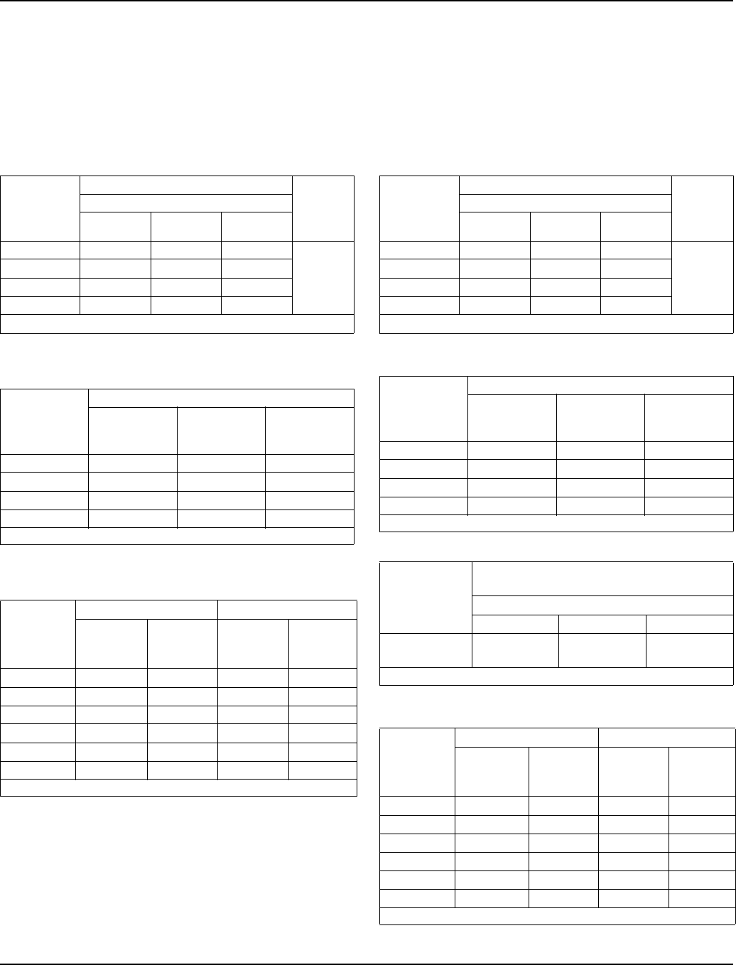
Refrigeration System Section 7
7-42 Part Number 80-1480-3
S1400 SERIES
Self-Contained Air-Cooled
NOTE: These characteristics may vary depending on
operating conditions.
Cycle Times
Freeze Time + Harvest Time = Total Cycle Time
24 Hour Ice Production
Operating Pressures
S1400 SERIES
Self-Contained Water-Cooled
NOTE: These characteristics may vary depending on
operating conditions.
Cycle Times
Freeze Time + Harvest Time = Total Cycle Time
24 Hour Ice Production
Operating Pressures
Air Temp.
Entering
Condenser
°F/°C
Freeze Time Harvest
Time
Water Temperature °F/°C
50/10.0 70/21.1 90/32.2
70/21.1 8.4-9.4 9.4-10.5 10.0-11.2
1-2.580/26.7 8.9-9.9 9.9-11.1 10.8-12.0
90/32.2 10.2-11.2 10.9-12.2 11.8-13.2
100/37.8 11.6-12.9 12.8-14.2 13.8-15.4
Times in minutes
Air Temp.
Entering
Condenser
°F/°C
Water Temperature °F/°C
50/10.0 70/21.1 90/32.2
70/21.1 1450 1320 1250
80/26.7 1390 1260 1170
90/32.2 1250 1160 1080
100/37.8 1100 1010 940
Based on average ice slab weight of 10 - 11 lb
Air Temp.
Entering
Condenser
°F/°C
Freeze Cycle Harvest Cycle
Discharge
Pressure
PSIG
Suction
Pressure
PSIG
Discharge
Pressure
PSIG
Suction
Pressure
PSIG
50/10.0 220-280 40-28 150-180 70-90
70/21.1 220-280 42-28 160-180 70-90
80/26.7 225-290 44-30 160-180 70-90
90/32.2 260-310 46-30 180-200 80-100
100/37.8 290-360 48-31 200-220 90-115
110/43.3 320-400 50-32 220-250 100-140
Suction pressure drops gradually throughout the freeze cycle
Air Temp.
Around Ice
Machine
°F/°C
Freeze Time Harvest
Time
Water Temperature °F/°C
50/10.0 70/21.1 90/32.2
70/21.1 8.9-10.0 9.8-10.9 11.2-12.5
1-2.5
80/26.7 8.9-10.0 9.8-10.9 11.4-12.6
90/32.2 8.9-10.0 9.6-10.7 11.6-12.9
100/37.8 9.0-10.1 10.0-11.2 11.7-13.0
Times in minutes
Air Temp.
Around Ice
Machine
°F/°C
Water Temperature °F/°C
50/10.0 70/21.1 90/32.2
70/21.1 1380 1280 1130
80/26.7 1380 1280 1120
90/32.2 1380 1300 1100
100/37.8 1370 1250 1090
Based on average ice slab weight of 10 - 11 lb
Condenser
Water
Consumption
90/32.2 Air Temperature
Around Ice Machine
Water Temperature °F/°C
59/15.0 70/21.1 90/32.2
Gal / per
100 lbs of ice 90 145 590
Water regulating valve set to maintain 240 PSIG discharge pressure
Air Temp.
Around Ice
Machine
°F/°C
Freeze Cycle Harvest Cycle
Discharge
Pressure
PSIG
Suction
Pressure
PSIG
Discharge
Pressure
PSIG
Suction
Pressure
PSIG
50/10.0 235-245 40-28 160-175 70-90
70/21.1 235-245 42-29 160-175 75-100
80/26.7 235-260 42-30 170-195 80-105
90/32.2 240-270 42-30 180-200 85-110
100/37.8 250-280 43-30 185-200 90-110
110/43.3 250-285 44-31 190-205 90-115
Suction pressure drops gradually throughout the freeze cycle
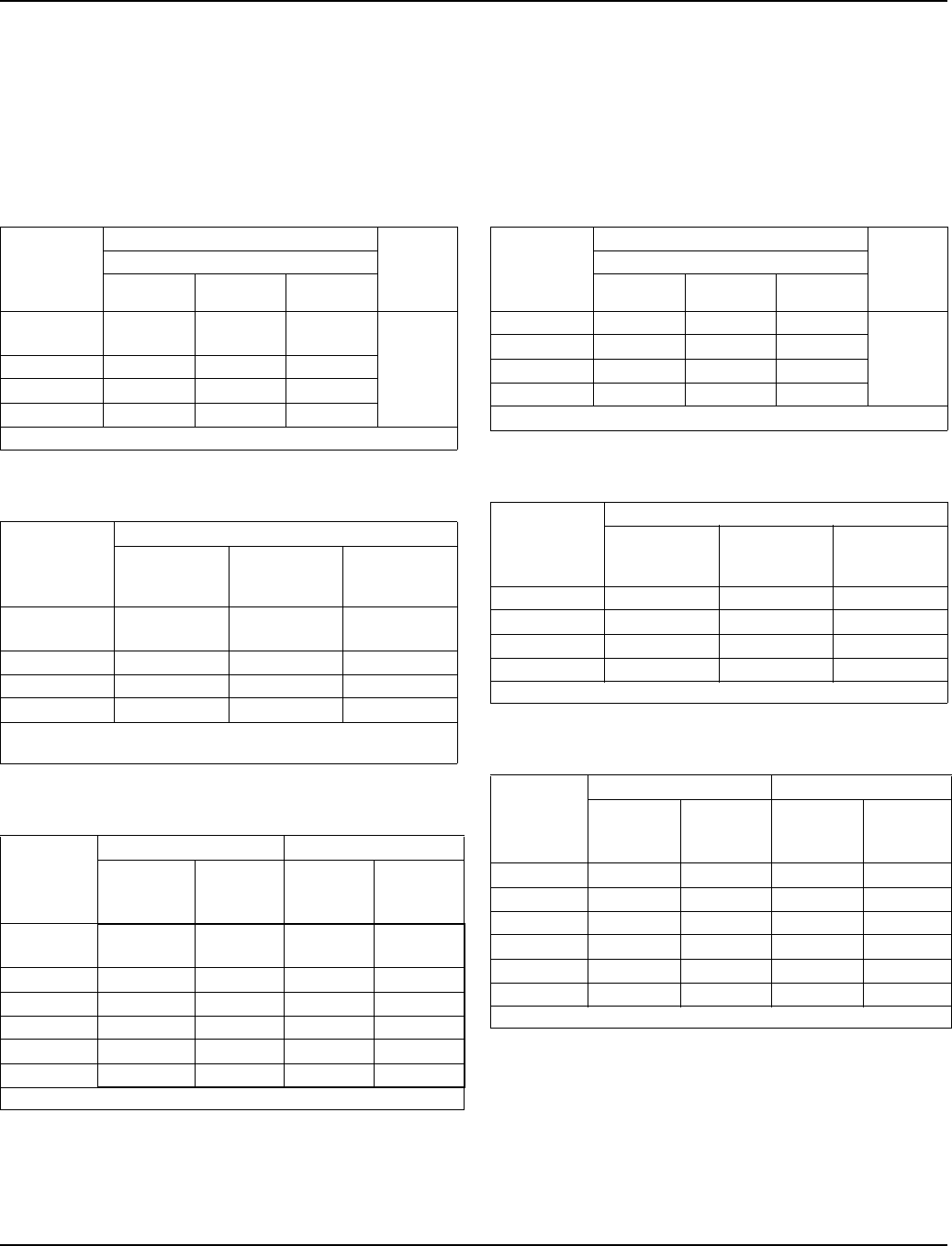
Section 7 Refrigeration System
Part Number 80-1480-3 7-43
S1400 SERIES
Remote
NOTE: These characteristics may vary depending on
operating conditions.
Cycle Times
Freeze Time + Harvest Time = Total Cycle Time
24 Hour Ice Production
Operating Pressures
S1600 SERIES
Self-Contained Air-Cooled
NOTE: These characteristics may vary depending on
operating conditions.
Cycle Times
Freeze Time + Harvest Time = Total Cycle Time
24 Hour Ice Production
Operating Pressures
Air Temp.
Entering
Condenser
°F/°C
Freeze Time Harvest
Time
Water Temperature °F/°C
50/10.0 70/21.1 90/32.2
-20/-28.9 to
70/21.1 9.1-10.1 10.1-11.3 11.0-12.3
1-2.5
80/26.7 9.2-10.2 10.0-11.2 11.2-12.5
90/32.2 9.4-10.5 10.4-11.6 11.4-12.6
100/37.8 9.9-11.1 11.1-12.4 12.3-13.7
Times in minutes
Air Temp.
Entering
Condenser
°F/°C
Water Temperature °F/°C
50/10.0 70/21.1 90/32.2
-20/-28.9 to
70/21.1 1360 1240 1150
80/26.7 1350 1250 1130
90/32.2 1320 1210 1120
100/37.8 1260 1140 1040
Based on average ice slab weight of 10 - 11 lb
Ratings with JC1395 condenser
Air Temp.
Entering
Condenser
°F/°C
Freeze Cycle Harvest Cycle
Discharge
Pressure
PSIG
Suction
Pressure
PSIG
Discharge
Pressure
PSIG
Suction
Pressure
PSIG
-20/-28.9 to
50/10.0 210-240 38-28 100-160 70-85
70/21.1 240-265 40-28 110-170 70-90
80/26.7 250-275 41-29 110-180 70-95
90/32.2 250-290 42-30 110-180 70-95
100/37.8 275-335 43-31 110-185 75-100
110/43.3 310-375 45-32 120-190 80-100
Suction pressure drops gradually throughout the freeze cycle
Air Temp.
Entering
Condenser
°F/°C
Freeze Time Harvest
Time
Water Temperature °F/°C
50/10.0 70/21.1 90/32.2
70/21.1 9.6-10.5 10.7-11.7 11.1-12.2
1-2.580/26.7 10.0-11.0 11.3-12.4 12.1-13.2
90/32.2 11.1-12.2 12.2-13.3 12.2-13.3
100/37.8 12.5-13.7 13.7-15.0 15.1-16.5
Times in minutes
Air Temp.
Entering
Condenser
°F/°C
Water Temperature °F/°C
50/10.0 70/21.1 90/32.2
70/21.1 1690 1540 1480
80/26.7 1630 1460 1380
90/32.2 1490 1370 1370
100/37.8 1340 1230 1130
Based on average ice slab weight of 13.0 - 14.125 lb
Air Temp.
Entering
Condenser
°F/°C
Freeze Cycle Harvest Cycle
Discharge
Pressure
PSIG
Suction
Pressure
PSIG
Discharge
Pressure
PSIG
Suction
Pressure
PSIG
50/10.0 220-280 46-27 150-165 70-90
70/21.1 220-280 50-28 150-165 70-90
80/26.7 240-300 55-32 155-175 75-95
90/32.2 270-330 58-34 165-185 80-100
100/37.8 310-375 65-36 185-200 90-105
110/43.3 330-415 70-38 200-245 95-115
Suction pressure drops gradually throughout the freeze cycle
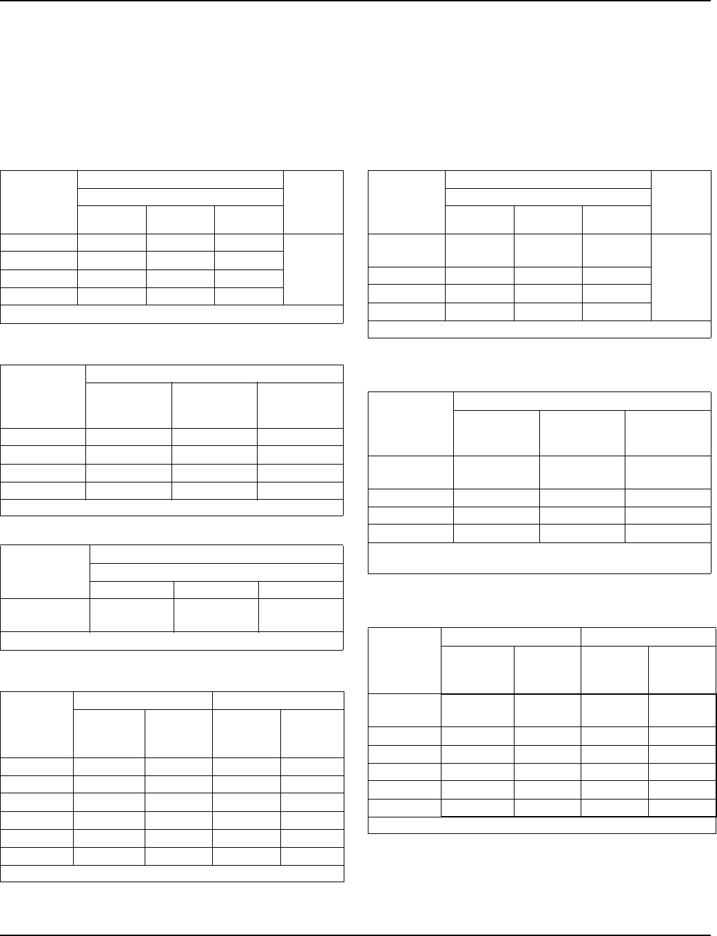
Refrigeration System Section 7
7-44 Part Number 80-1480-3
S1600 SERIES
Self-Contained Water-Cooled
NOTE: These characteristics may vary depending on
operating conditions.
Cycle Times
Freeze Time + Harvest Time = Total Cycle Time
24 Hour Ice Production
Operating Pressures
S1600 SERIES
Remote
NOTE: These characteristics may vary depending on
operating conditions.
Cycle Times
Freeze Time + Harvest Time = Total Cycle Time
24 Hour Ice Production
Operating Pressures
Air Temp.
Around Ice
Machine
°F/°C
Freeze Time Harvest
Time
Water Temperature °F/°C
50/10.0 70/21.1 90/32.2
70/21.1 9.8-10.8 10.9-12.0 12.4-13.6
1-2.5
80/26.7 10.1-11.1 11.0-12.1 12.7-13.9
90/32.2 10.2-11.2 11.1-12.2 12.8-14.0
100/37.8 10.4-11.5 11.4-12.5 13.0-14.3
Times in minutes
Air Temp.
Around Ice
Machine
°F/°C
Water Temperature °F/°C
50/10.0 70/21.1 90/32.2
70/21.1 1660 1510 1350
80/26.7 1610 1500 1320
90/32.2 1600 1480 1310
100/37.8 1570 1450 1290
Based on average ice slab weight of 13.0 - 14.125 lb
Condenser
Water
Consumption Air Temperature / Water Temperature °F
59/15.0 70/21.1 90/32.2
Gal / per
100 lbs of ice 100 150 550
Water regulating valve set to maintain 240 PSIG discharge pressure
Air Temp.
Around Ice
Machine
°F/°C
Freeze Cycle Harvest Cycle
Discharge
Pressure
PSIG
Suction
Pressure
PSIG
Discharge
Pressure
PSIG
Suction
Pressure
PSIG
50/10.0 235-245 46-27 160-175 70-90
70/21.1 235-275 50-27 160-180 70-95
80/26.7 240-280 52-28 160-190 70-100
90/32.2 240-285 52-28 160-190 75-100
100/37.8 250-290 52-29 165-195 75-100
110/43.3 255-295 52-30 170-200 80-100
Suction pressure drops gradually throughout the freeze cycle
Air Temp.
Entering
Condenser
°F/°C
Freeze Time Harvest
Time
Water Temperature °F/°C
50/10.0 70/21.1 90/32.2
-20/-28.9 to
70/21.1 10.4-11.5 11.2-12.3 12.4-13.6
1-2.5
80/26.7 10.5-11.5 11.7-12.8 12.5-13.7
90/32.2 10.8-11.9 11.7-12.8 13.0-14.3
100/37.8 11.7-12.8 12.9-14.1 13.8-15.2
Times in minutes
Air Temp.
Entering
Condenser
°F/°C
Water Temperature °F/°C
50/10.0 70/21.1 90/32.2
-20/-28.9 to
70/21.1 1570 1470 1350
80/26.7 1560 1420 1340
90/32.2 1520 1420 1290
100/37.8 1420 1300 1220
Based on average ice slab weight of 13.0 - 14.125 lb
Ratings with JC1395 condenser
Air Temp.
Entering
Condenser
°F/°C
Freeze Cycle Harvest Cycle
Discharge
Pressure
PSIG
Suction
Pressure
PSIG
Discharge
Pressure
PSIG
Suction
Pressure
PSIG
-20/-28.9 to
50/10.0 220-230 40-28 100-160 65-85
70/21.1 250-275 50-28 100-170 70-85
80/26.7 250-290 50-28 100-175 70-90
90/32.2 255-300 52-30 100-175 75-95
100/37.8 270-340 54-31 110-180 75-95
110/43.3 310-370 56-32 120-190 80-100
Suction pressure drops gradually throughout the freeze cycle
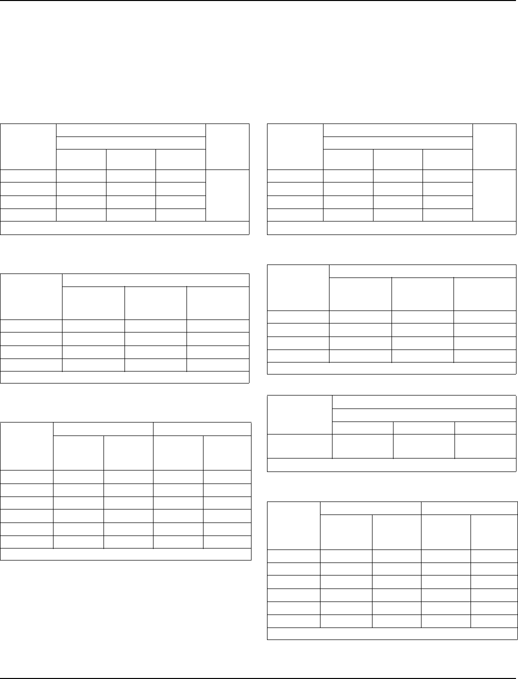
Section 7 Refrigeration System
Part Number 80-1480-3 7-45
S1800 SERIES
Self-Contained Air-Cooled
NOTE: These characteristics may vary depending on
operating conditions.
Cycle Times
Freeze Time + Harvest Time = Total Cycle Time
24 Hour Ice Production
Operating Pressures
S1800 SERIES
Self-Contained Water-Cooled
NOTE: These characteristics may vary depending on
operating conditions.
Cycle Times
Freeze Time + Harvest Time = Total Cycle Time
24 Hour Ice Production
Operating Pressures
Air Temp.
Entering
Condenser
°F/°C
Freeze Time Harvest
Time
Water Temperature °F/°C
50/10.0 70/21.1 90/32.2
70/21.1 8.7-9.6 9.6-10.6 10.4-11.5
1-2.580/26.7 9.4-10.3 10.2-11.2 10.9-12.0
90/32.2 10.0-11.0 10.7-11.8 11.8-12.9
100/37.8 11.2-12.3 12.2-13.3 13.0-14.3
Times in minutes
Air Temp.
Entering
Condenser
°F/°C
Water Temperature °F/°C
50/10.0 70/21.1 90/32.2
70/21.1 1830 1680 1570
80/26.7 1720 1600 1510
90/32.2 1630 1530 1410
100/37.8 1470 1370 1290
Based on average ice slab weight of 13 - 14.125 lb
Air Temp.
Entering
Condenser
°F/°C
Freeze Cycle Harvest Cycle
Discharge
Pressure
PSIG
Suction
Pressure
PSIG
Discharge
Pressure
PSIG
Suction
Pressure
PSIG
50/10.0 220-255 40-25 160-170 70-85
70/21.1 220-275 40-26 160-180 70-85
80/26.7 225-290 42-28 175-200 80-95
90/32.2 260-330 44-28 175-200 80-95
100/37.8 300-380 46-30 190-215 90-110
110/43.3 320-415 50-30 210-250 105-140
Suction pressure drops gradually throughout the freeze cycle
Air Temp.
Around Ice
Machine
°F/°C
Freeze Time Harvest
Time
Water Temperature °F/°C
50/10.0 70/21.1 90/32.2
70/21.1 8.5-9.4 9.2-10.1 10.7-11.8
.1-2.5
80/26.7 8.5-9.4 9.3-10.3 10.9-12.0
90/32.2 8.6-9.4 9.4-10.4 11.1-12.2
100/37.8 8.7-9.6 9.6-10.5 11.2-12.3
Times in minutes
Air Temp.
Around Ice
Machine
°F/°C
Water Temperature °F/°C
50/10.0 70/21.1 90/32.2
70/21.1 1870 1750 1530
80/26.7 1870 1730 1510
90/32.2 1860 1710 1490
100/37.8 1830 1690 1470
Based on average ice slab weight of 13- 14.125 lb
Condenser
Water
Consumption Air Temperature / Water Temperature °F
59/15.0 70/21.1 90/32.2
Gal / per
100 lbs of ice 95 155 510
Water regulating valve set to maintain 240 PSIG discharge pressure
Air Temp.
Around Ice
Machine
°F/°C
Freeze Cycle Harvest Cycle
Discharge
Pressure
PSIG
Suction
Pressure
PSIG
Discharge
Pressure
PSIG
Suction
Pressure
PSIG
50/10.0 235-245 40-25 160-190 70-90
70/21.1 235-265 40-26 160-190 70-90
80/26.7 240-270 42-26 165-190 70-90
90/32.2 240-275 45-27 165-190 70-90
100/37.8 245-280 50-28 165-190 70-95
110/43.3 245-290 52-28 175-200 80-100
Suction pressure drops gradually throughout the freeze cycle
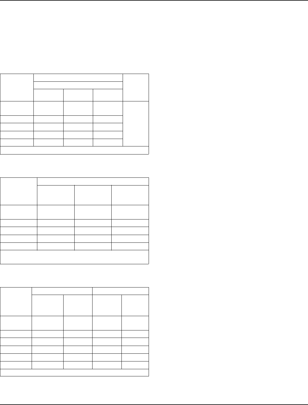
Refrigeration System Section 7
7-46 Part Number 80-1480-3
S1800 SERIES
Remote
NOTE: These characteristics may vary depending on
operating conditions.
Cycle Times
Freeze Time + Harvest Time = Total Cycle Time
24 Hour Ice Production
Operating Pressures
Air Temp.
Entering
Condenser
°F/°C
Freeze Time Harvest
Time
Water Temperature °F/°C
50/10.0 70/21.1 90/32.2
-20/-28.9 to
70/21.1 8.9-9.8 10.0-11.0 10.7-11.7
1-2.5
80/26.7 9.0-9.9 10.1-11.1 10.8-11.9
90/32.2 9.2-10.1 10.1-11.1 10.8-11.9
100/37.8 9.6-10.5 10.0-11.0 11.6-12.7
110/43.3 10.4-11.5 11.5-12.6 12.5-13.7
Times in minutes
Air Temp.
Entering
Condenser
°F/°C
Water Temperature °F/°C
50/10.0 70/21.1 90/32.2
-20/-28.9 to
70/21.1 1800 1630 1540
80/26.7 1780 1620 1520
90/32.2 1750 1610 1520
100/37.8 1690 1630 1430
110/43.3 1570 1440 1340
Based on average ice slab weight of 13- 14.125 lb
Ratings with JC1395 condenser
Air Temp.
Entering
Condenser
°F/°C
Freeze Cycle Harvest Cycle
Discharge
Pressure
PSIG
Suction
Pressure
PSIG
Discharge
Pressure
PSIG
Suction
Pressure
PSIG
-20/-28.9 to
50/10.0 250-220 44-26 110-170 65-85
70/21.1 280-240 50-28 115-180 70-90
80/26.7 290-245 50-28 115-180 70-90
90/32.2 300-250 52-28 120-195 70-90
100/37.8 340-260 60-28 125-210 70-90
110/43.3 390-295 60-30 125-220 80-100
Suction pressure drops gradually throughout the freeze cycle
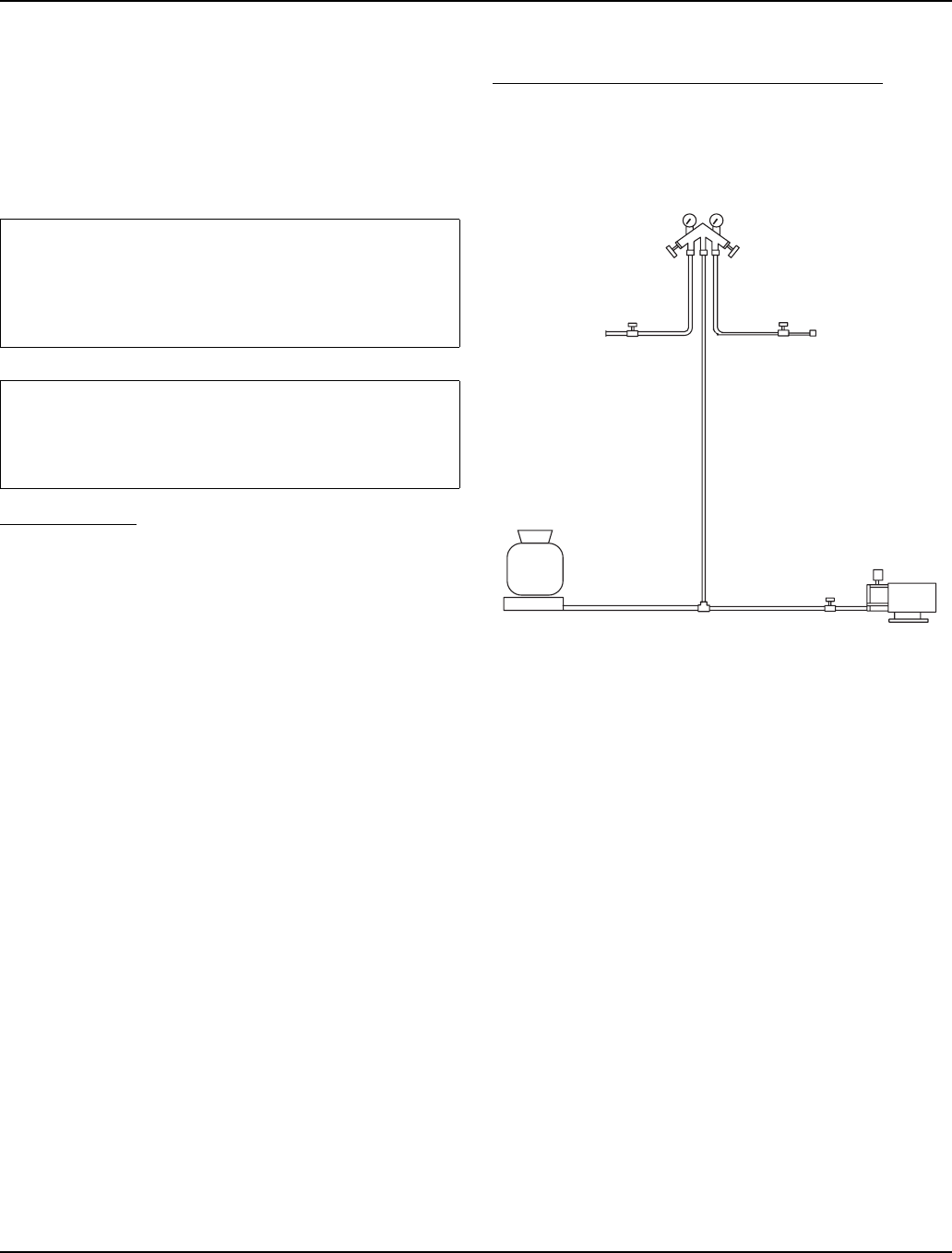
Section 7 Refrigeration System
Part Number 80-1480-3 7-47
Refrigerant Recovery/Evacuation and Recharging
NORMAL SELF-CONTAINED MODEL PROCEDURES
Refrigerant Recovery/Evacuation
Do not purge refrigerant to the atmosphere. Capture
refrigerant using recovery equipment. Follow the
manufacturer’s recommendations.
CONNECTIONS
Manifold gauge sets must utilize low loss fittings to
comply with U.S. Government rules and regulations.
Make these connections:
1. Suction side of the compressor through the suction
service valve.
2. Discharge side of the compressor through the
discharge service valve.
SELF-CONTAINED RECOVERY/EVACUATION
1. Place the toggle switch in the OFF position.
2. Install manifold gauges, scale, and recovery unit or
two-stage vacuum pump.
Figure 7-13. Recovery/Evacuation Connections
3. Open (backseat) the high and low side ice machine
service valves, and open high and low side on
manifold gauges.
4. Perform recovery or evacuation:
A. Recovery: Operate the recovery unit as directed
by the manufacturer’s instructions.
B. Evacuation prior to recharging: Pull the system
down to 500 microns. Then, allow the pump to
run for an additional half hour. Turn off the pump
and perform a standing vacuum leak check.
5. Follow the Charging Procedures.
Important
Manitowoc Ice, Inc. assumes no responsibility for
the use of contaminated refrigerant. Damage
resulting from the use of contaminated refrigerant is
the sole responsibility of the servicing company.
Important
Replace the liquid line drier before evacuating and
recharging. Use only a Manitowoc (O.E.M.) liquid
line filter drier to prevent voiding the warranty.
MANIFOLD SET
OPEN
BACKSEATED
VACUUM PUMP/
RECOVERY UNIT
CLOSED
OPEN
LOW SIDE
SERVICE
VALVE
HIGH SIDE
SERVICE
VALVE
BACKSEATED
OPEN
SV1404A
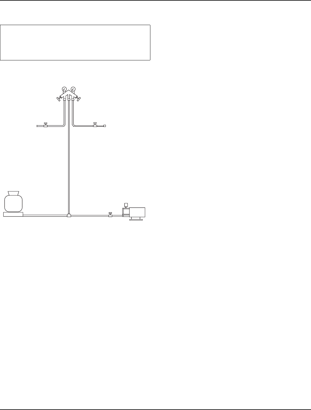
Refrigeration System Section 7
7-48 Part Number 80-1480-3
Self-Contained Charging Procedures
1. Be sure the toggle switch is in the OFF position.
Figure 7-14. Charging Connections
2. Close the vacuum pump valve, the low side service
valve, and the low side manifold gauge valve.
3. Open the high side manifold gauge valve, and
backseat the high side service valve.
4. Open the charging cylinder and add the proper
refrigerant charge (shown on nameplate) through
the discharge service valve.
5. Let the system “settle” for 2 to 3 minutes.
6. Place the toggle switch in the ICE position.
7. Close the high side on the manifold gauge set. Add
any remaining vapor charge through the suction
service valve (if necessary).
NOTE: Manifold gauges must be removed properly to
ensure that no refrigerant contamination or loss occurs.
8. Make sure that all of the vapor in the charging hoses
is drawn into the ice machine before disconnecting
the charging hoses.
A. Run the ice machine in freeze cycle.
B. Close the high side service valve at the ice
machine.
C. Open the low side service valve at the ice
machine.
D. Open the high and low side valves on the
manifold gauge set. Any refrigerant in the lines
will be pulled into the low side of the system.
E. Allow the pressures to equalize while the ice
machine is in the freeze cycle.
F. Close the low side service valve at the ice
machine.
G. Remove the hoses from the ice machine and
install the caps.
Important
The charge is critical on all Manitowoc ice
machines. Use a scale or a charging cylinder to
ensure the proper charge is installed.
MANIFOLD SET
CLOSED
FRONTSEATED
CHARGING
CYLINDER VACUUM PUMP/
RECOVERY UNIT
OPEN
CLOSED
LOW SIDE
SERVICE
VALVE
HIGH SIDE
SERVICE
VALVE
BACKSEATED
OPEN
SV1404B

Section 7 Refrigeration System
Part Number 80-1480-3 7-49
NORMAL REMOTE MODEL PROCEDURES
Refrigerant Recovery/Evacuation
Do not purge refrigerant to the atmosphere. Capture
refrigerant using recovery equipment. Follow the
manufacturer’s recommendations.
CONNECTIONS
Make these connections:
• Suction side of the compressor through the suction
service valve.
• Discharge side of the compressor through the
discharge service valve.
• Receiver outlet service valve, which evacuates the
area between the check valve in the liquid line and
the pump down solenoid.
• Access (Schrader) valve on the discharge line quick-
connect fitting, located on the outside of the
compressor/evaporator compartment. This
connection evacuates the condenser. Without it, the
magnetic check valves would close when the
pressure drops during evacuation, preventing
complete evacuation of the condenser.
NOTE: Manitowoc recommends using an access valve
core removal and installation tool on the discharge line
quick-connect fitting. This permits access valve core
removal. This allows for faster evacuation and charging,
without removing the manifold gauge hose.
REMOTE RECOVERY/EVACUATION
1. Place the toggle switch in the OFF position.
2. Install manifold gauges, charging cylinder/scale, and
recovery unit or two-stage vacuum pump.
3. Open (backseat) the high and low side ice machine
service valves.
4. Open the receiver service valve halfway.
5. Open high and low side on the manifold gauge set.
6. Perform recovery or evacuation:
A. Recovery: Operate the recovery unit as directed
by the manufacturer’s instructions.
B. Evacuation prior to recharging: Pull the system
down to 500 microns. Then, allow the pump to
run for an additional hour. Turn off the pump and
perform a standing vacuum leak check.
NOTE: Check for leaks using a halide or electronic leak
detector after charging the ice machine.
7. Refer to Charging Procedures.
Important
Manitowoc Ice, Inc. assumes no responsibility for
the use of contaminated refrigerant. Damage
resulting from the use of contaminated refrigerant is
the sole responsibility of the servicing company.
Important
Replace the liquid line drier before evacuating and
recharging. Use only a Manitowoc (O.E.M.) liquid
line filter drier to prevent voiding the warranty.
Important
Recovery/evacuation of a remote system requires
connections at four points for complete system
evacuation. See the drawing on next page.
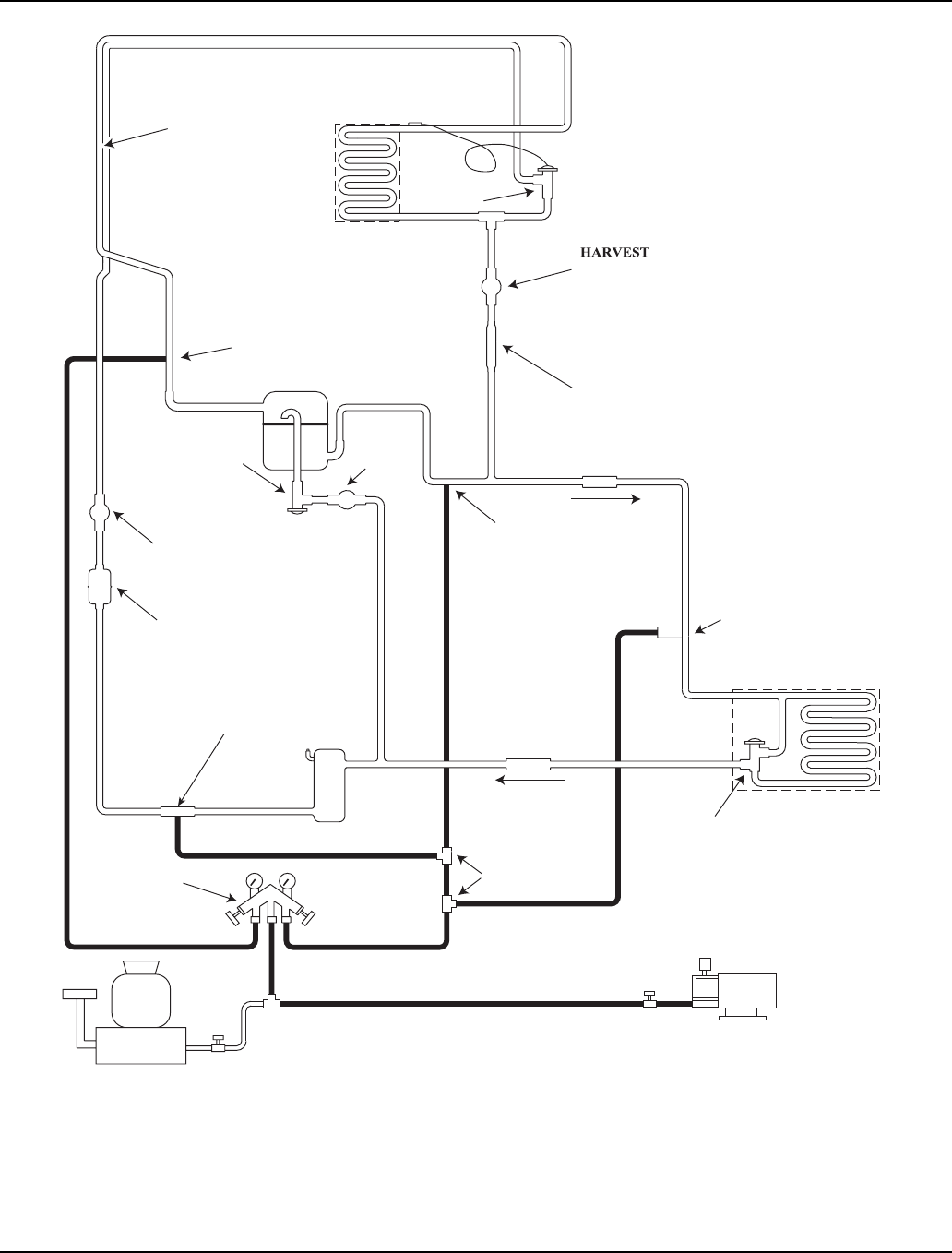
Refrigeration System Section 7
7-50 Part Number 80-1480-3
Figure 7-15. Recovery/Evacuation Connections
x
x
x
SCHRAEDER FITTING
QUICK CONNECT
DISCHARGE LINE
CONTROL VALVE
HEAD PRESSURE
REMOTE CONDENSE
R
CLOSED
SCALE
OPEN
RECOVERY UNIT
VACUUM PUMP/
SERVICE VALVE
1/2 OPEN
RECEIVER
MANIFOLD SET
OPEN
DRIER
SOLENOID
LINE
VALVE
REGULATING
PRESSURE
HARVEST
LIQUID
(BACKSEATED)
SERVICE VALVE
CHECK VALVE
TEE
OPEN
C
B
R
HIGH SIDE
(BACKSEATED)
SERVICE VALVE
LOW SIDE
COMPRESSOR
HARVEST
PRESSURE
SOLENOID
VALVE
VALVE
EXPANSION
VALVE
CHECK
STRAINER
VALVES
SOLENOID
HEAT EXCHANGER
EVAPORATOR
SV1461

Section 7 Refrigeration System
Part Number 80-1480-3 7-51
Remote Charging Procedures
1. Be sure the toggle switch is in the OFF position.
2. Close the vacuum pump valve, the low and high side
service valves (frontseat), and the low side manifold
gauge valve.
3. Open the charging cylinder and add the proper
refrigerant charge (shown on nameplate) into the
system high side (receiver outlet valve and
discharge lines quick-connect fitting).
4. If the high side does not take the entire charge,
close the high side on the manifold gauge set, and
backseat (open) the low side service valve and
receiver outlet service valve. Start the ice machine
and add the remaining charge through the low side
(in vapor form) until the machine is fully charged.
5. Ensure all vapor in charging hoses is drawn into the
machine, then disconnect the manifold gauges.
NOTE: Backseat the receiver outlet service valve after
charging is complete and before operating the ice
machine. If the access valve core removal and
installation tool is used on the discharge quick-connect
fitting, reinstall the Schraeder valve core before
disconnecting the access tool and hose.
6. Run the ice machine in freeze cycle.
7. Close the high side service valve at the ice machine.
8. Open the low side service valve at the ice machine.
9. Open the high and low side valves on the manifold
gauge set. Any refrigerant in the lines will be pulled
into the low side of the system.
10. Allow the pressures to equalize while the ice
machine is in the freeze cycle.
11. Close the low side service valve at the ice machine.
12. Remove the hoses from the ice machine and install
the caps.
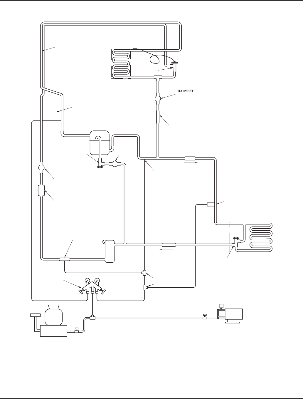
Refrigeration System Section 7
7-52 Part Number 80-1480-3
x
x
x
SCHRAEDER FITTING
QUICK CONNECT
DISCHARGE LINE
CONTROL VALVE
HEAD PRESSURE
REMOTE CONDENSER
CLOSED
CLOSED
SCALE RECOVERY UNIT
VACUUM PUMP/
SERVICE VALVE
1/2 OPEN
RECEIVER
MANIFOLD SET
OPEN
DRIER
SOLENOID
LINE
VALVE
REGULATING
PRESSURE
HARVEST
LIQUID
(BACKSEATED)
SERVICE VALVE
CHECK VALVE
TEE
OPEN
C
B
R
HIGH SIDE
(BACKSEATED)
SERVICE VALVE
LOW SIDE
COMPRESSOR
HARVEST
PRESSURE
SOLENOID
VALVE
VALVE
EXPANSION
VALVE
CHECK
STRAINER
VALVES
SOLENOID
HEAT EXCHANGER EVAPORATOR
SV1462
Figure 7-16. Remote Charging Connections

Section 7 Refrigeration System
Part Number 80-1480-3 7-53
SYSTEM CONTAMINATION CLEAN-UP
General
This section describes the basic requirements for
restoring contaminated systems to reliable service.
Determining Severity Of Contamination
System contamination is generally caused by either
moisture or residue from compressor burnout entering
the refrigeration system.
Inspection of the refrigerant usually provides the first
indication of system contamination. Obvious moisture or
an acrid odor in the refrigerant indicates contamination.
If either condition is found, or if contamination is
suspected, use a Total Test Kit from Totaline or a similar
diagnostic tool. These devices sample refrigerant,
eliminating the need to take an oil sample. Follow the
manufacturer’s directions.
If a refrigerant test kit indicates harmful levels of
contamination, or if a test kit is not available, inspect the
compressor oil.
1. Remove the refrigerant charge from the ice
machine.
2. Remove the compressor from the system.
3. Check the odor and appearance of the oil.
4. Inspect open suction and discharge lines at the
compressor for burnout deposits.
5. If no signs of contamination are present, perform an
acid oil test.
Check the chart below to determine the type of cleanup
required.
Important
Manitowoc Ice, Inc. assumes no responsibility for
the use of contaminated refrigerant. Damage
resulting from the use of contaminated refrigerant is
the sole responsibility of the servicing company.
Contamination/Cleanup Chart
Symptoms/Findings Required Cleanup Procedure
No symptoms or suspicion of contamination Normal evacuation/recharging procedure
Moisture/Air Contamination symptoms
Refrigeration system open to atmosphere for longer than 15
minutes
Refrigeration test kit and/or acid oil test shows contamination
Leak in water-cooled condenser
No burnout deposits in open compressor lines
Mild contamination cleanup procedure
Mild Compressor Burnout symptoms
Oil appears clean but smells acrid
Refrigeration test kit or acid oil test shows harmful acid content
No burnout deposits in open compressor lines
Mild contamination cleanup procedure
Severe Compressor Burnout symptoms
Oil is discolored, acidic, and smells acrid
Burnout deposits found in the compressor and lines, and in
other components
Severe contamination cleanup procedure

Refrigeration System Section 7
7-54 Part Number 80-1480-3
Mild System Contamination Cleanup Procedure
1. Replace any failed components.
2. If the compressor is good, change the oil.
3. Replace the liquid line drier.
NOTE: If the contamination is from moisture, use heat
lamps during evacuation. Position them at the
compressor, condenser and evaporator prior to
evacuation. Do not position heat lamps too close to
plastic components, or they may melt or warp.
4. Follow the normal evacuation procedure, except
replace the evacuation step with the following:
A. Pull vacuum to 1000 microns. Break the vacuum
with dry nitrogen and sweep the system.
Pressurize to a minimum of 5 psi (35 kPa).
B. Pull vacuum to 500 microns. Break the vacuum
with dry nitrogen and sweep the system.
Pressurize to a minimum of 5 psi (35 kPa).
C. Change the vacuum pump oil.
D. Pull vacuum to 500 microns. Run the vacuum
pump for 1/2 hour on self-contained models, 1
hour on remotes.
NOTE: You may perform a standing vacuum test to
make a preliminary leak check. You should use an
electronic leak detector after system charging to be sure
there is no leak.
5. Charge the system with the proper refrigerant to the
nameplate charge.
6. Operate the ice machine.
Severe System Contamination Cleanup Procedure
1. Remove the refrigerant charge.
2. Remove the compressor.
3. Disassemble the harvest solenoid valve. If burnout
deposits are found inside the valve, install a new
harvest valve, and replace manifold strainer, TXV
and harvest pressure regulating valve.
4. Wipe away any burnout deposits from suction and
discharge lines at compressor.
5. Sweep through the open system with dry nitrogen.
6. Install a new compressor and new start components.
7. Install a suction line filter-drier with acid and
moisture removal capability (P/N 89-3028-3). Place
the filter drier as close to the compressor as
possible.
8. Install an access valve at the inlet of the suction line
drier.
9. Install a new liquid line drier.
Continued on next page …
Important
Dry nitrogen is recommended for this procedure.
This will prevent CFC release. Important
Refrigerant sweeps are not recommended, as they
release CFC’s into the atmosphere.
Section 7 Refrigeration System
Part Number 80-1480-3 7-55
10. Follow the normal evacuation procedure, except
replace the evacuation step with the following:
A. Pull vacuum to 1000 microns. Break the vacuum
with dry nitrogen and sweep the system.
Pressurize to a minimum of 5 psi (35 kPa .35 bar).
B. Change the vacuum pump oil.
C. Pull vacuum to 500 microns. Break the vacuum
with dry nitrogen and sweep the system.
Pressurize to a minimum of 5 psi (35 kPa .35 bar).
D. Change the vacuum pump oil.
E. Pull vacuum to 500 microns. Run the vacuum
pump for 1/2 hour on self-contained models, 1
hour on remotes.
NOTE: You may perform a standing vacuum test to
make a preliminary leak check. You should use an
electronic leak detector after system charging to be sure
there is no leak.
11. Charge the system with the proper refrigerant to the
nameplate charge.
12. Operate the ice machine for one hour. Then, check
the pressure drop across the suction line filter-drier.
A. If the pressure drop is less than 1 psi (7 kPa,
.7 bar), the filter-drier should be adequate for
complete cleanup.
B. If the pressure drop exceeds 1 psi (7 kPa, .7 bar),
change the suction line filter-drier and the liquid
line drier. Repeat until the pressure drop is
acceptable.
13. Operate the ice machine for 48-72 hours. Then,
remove the suction line drier and change the liquid
line drier.
14. Follow normal evacuation procedures.
REPLACING PRESSURE CONTROLS WITHOUT
REMOVING REFRIGERANT CHARGE
This procedure reduces repair time and cost. Use it
when any of the following components require
replacement, and the refrigeration system is operational
and leak-free.
• Fan cycle control (air-cooled only)
• Water regulating valve (water-cooled only)
• High pressure cut-out control
• High side service valve
• Low side service valve
1. Disconnect power to the ice machine.
2. Follow all manufacturer’s instructions supplied with
the pinch-off tool. Position the pinch-off tool around
the tubing as far from the pressure control as
feasible. (See the figure on next page.) Clamp down
on the tubing until the pinch-off is complete.
3. Cut the tubing of the defective component with a
small tubing cutter.
4. Solder the replacement component in place. Allow
the solder joint to cool.
5. Remove the pinch-off tool.
6. Re-round the tubing. Position the flattened tubing in
the proper hole in the pinch off tool. Tighten the
wingnuts until the block is tight and the tubing is
rounded. (See the drawing on next page.)
NOTE: The pressure controls will operate normally once
the tubing is re-rounded. Tubing may not re-round
100%.
Important
Dry nitrogen is recommended for this procedure.
This will prevent CFC release.
Important
This is a required in-warranty repair procedure.
!
Warning
Do not unsolder a defective component. Cut it out of
the system. Do not remove the pinch-off tool until
the new component is securely in place.
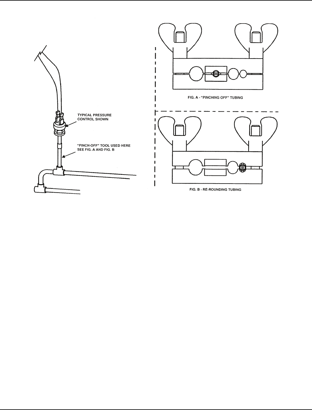
Refrigeration System Section 7
7-56 Part Number 80-1480-3
Figure 7-17. Using Pinch-Off Tool
SV1406

Section 7 Refrigeration System
Part Number 80-1480-3 7-57
FILTER-DRIERS
The filter-driers used on Manitowoc ice machines are
manufactured to Manitowoc specifications.
The difference between Manitowoc driers and off-the-
shelf driers is in filtration. Manitowoc driers have dirt-
retaining filtration, with fiberglass filters on both the inlet
and outlet ends. This is very important because ice
machines have a back-flushing action which takes place
during every harvest cycle.
These filter-driers have a very high moisture removal
capability and a good acid removal capability.
The size of the filter-drier is important. The refrigerant
charge is critical. Using an improperly sized filter-drier
will cause the ice machine to be improperly charged with
refrigerant.
Listed below are the recommended O.E.M. field
replacement driers:
Important
Driers are covered as a warranty part. The drier
must be replaced any time the system is opened for
repairs.
Model Drier
Size
End
Connection
Size
Part
Number
S300A S300W
S320A S320W
S420A S420W
S450A S450W
S500A S500W
S600A S600W
S850A S850W
S1000A S1000W
UK-032S 1/4" 89-3025-9
S1200A S1200W UK-052S 1/4" 89-3024-9
S500N S600N
S850N S1000N
S1400A S1400W
S1400N
S1600A S1600W
S1600N
S1800A S1800W
S1800N
UK-053S 3/8" 89-3027-9
Suction Filter UK-165S 5/8" 89-3028-3
Suction Filter used when cleaning up severely contaminated systems
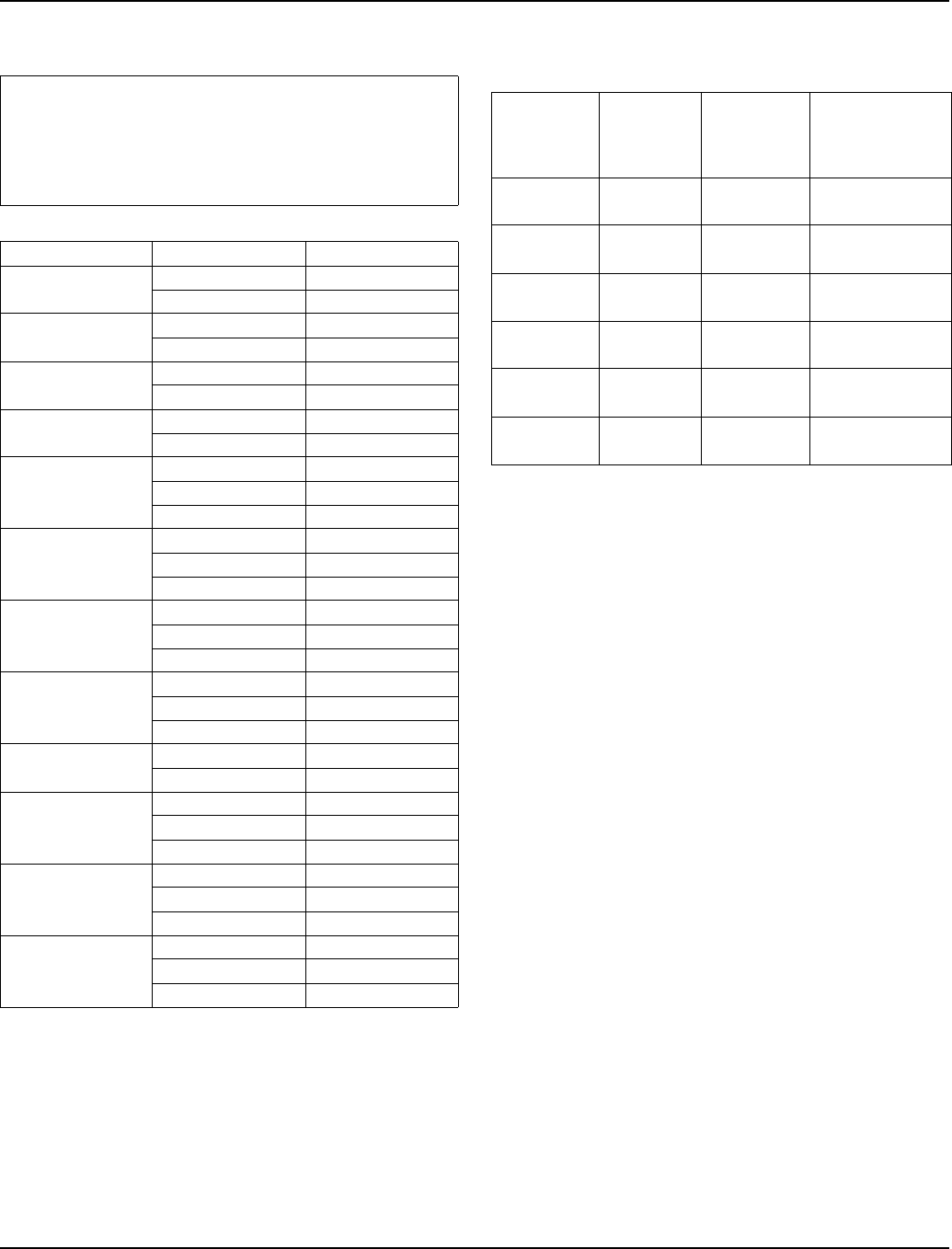
Refrigeration System Section 7
7-58 Part Number 80-1480-3
TOTAL SYSTEM REFRIGERANT CHARGES
NOTE: All ice machines on this list are charged using
R-404A refrigerant.
Additional Refrigerant Charges
For line sets between 50’ - 100’.
Important
This information is for reference only. Refer to the
ice machine serial number tag to verify the system
charge. Serial plate information overrides
information listed on this page.
Series Version Charge
S300 Air-Cooled 18 oz.
Water-Cooled 15 oz.
S320 Air-Cooled 20 oz.
Water-Cooled 19 oz.
S420 Air-Cooled 21 oz.
Water-Cooled 20 oz.
S450 Air-Cooled 21 oz.
Water-Cooled 20 oz.
S500
Air-Cooled 26 oz.
Water-Cooled 22 oz.
Remote 6 lb.
S600
Air-Cooled 32 oz.
Water-Cooled 28 oz.
Remote 6.5 lb.
S850
Air-Cooled 36 oz.
Water-Cooled 32 oz.
Remote 8.5 lb.
S1000
Air-Cooled 36 oz.
Water-Cooled 38 oz.
Remote 8.5 lb.
S1200 Air-Cooled 38 oz.
Water-Cooled 42 oz.
S1400
Air-Cooled 44 oz.
Water-Cooled 40 oz.
Remote 11 lb.
S1600
Air-Cooled 48 oz.
Water-Cooled 48 oz.
Remote 11.5 lb.
S1800
Air-Cooled 52 oz.
Water-Cooled 48 oz.
Remote 12.5 lb.
Series Nameplate
Charge
Refrigerant
to be added
for 50’ - 100’
line sets
Maximum
System Charge
Never Exceed
S500 6 lb.
(96 oz.)
1.5 lb.
(24 oz.)
7.5 lb.
(120 oz.)
S600 6.5 lb.
(104 oz.)
1.5 lb.
(24 oz.)
8.0 lb.
(128 oz.)
S850/S1000 8.5 lb.
(136 oz.)
2 lb.
(32 oz.)
10.5 lb.
(168 oz.)
S1400 11 lb.
(176 oz.)
2 lb.
(32 oz.)
13 lb.
(208 oz.)
S1600 11.5 lb.
(184 oz.)
2 lb.
(32 oz.)
13.5 lb.
(216 oz.)
S1800 12.5 lb.
(200 oz.)
1 lb.
(16 oz.)
13.5 lb.
(216 oz.)

Section 7 Refrigeration System
Part Number 80-1480-3 7-59
REFRIGERANT DEFINITIONS
Recover
To remove refrigerant, in any condition, from a system
and store it in an external container, without necessarily
testing or processing it in any way.
Recycle
To clean refrigerant for re-use by oil separation and
single or multiple passes through devices, such as
replaceable core filter-driers, which reduce moisture,
acidity and particulate matter. This term usually applies
to procedures implemented at the field job site or at a
local service shop.
Reclaim
To reprocess refrigerant to new product specifications
(see below) by means which may include distillation. A
chemical analysis of the refrigerant is required after
processing to be sure that product specifications are
met. This term usually implies the use of processes and
procedures available only at a reprocessing or
manufacturing facility.
Chemical analysis is the key requirement in this
definition. Regardless of the purity levels reached by a
reprocessing method, refrigerant is not considered
“reclaimed” unless it has been chemically analyzed and
meets ARI Standard 700 (latest edition).
New Product Specifications
This means ARI Standard 700 (latest edition). Chemical
analysis is required to assure that this standard is met.

Refrigeration System Section 7
7-60 Part Number 80-1480-3
REFRIGERANT RE-USE POLICY
Manitowoc recognizes and supports the need for proper
handling, re-use, and disposal of, CFC and HCFC
refrigerants. Manitowoc service procedures require
recapturing refrigerants, not venting them to the
atmosphere.
It is not necessary, in or out of warranty, to reduce or
compromise the quality and reliability of your customers’
products to achieve this.
Manitowoc approves the use of:
1. New Refrigerant
• Must be of original nameplate type.
2. Reclaimed Refrigerant
• Must be of original nameplate type.
• Must meet ARI Standard 700 (latest edition)
specifications.
3. Recovered or Recycled Refrigerant
• Must be recovered or recycled in accordance
with current local, state and federal laws.
• Must be recovered from and re-used in the same
Manitowoc product. Re-use of recovered or
recycled refrigerant from other products is not
approved.
• Recycling equipment must be certified to ARI
Standard 740 (latest edition) and be maintained
to consistently meet this standard.
• Recovered refrigerant must come from a
“contaminant-free” system. To decide whether
the system is contaminant free, consider:
– Type(s) of previous failure(s)
– Whether the system was cleaned, evacuated
and recharged properly following failure(s)
– Whether the system has been contaminated
by this failure
– Compressor motor burnouts and improper
past service prevent refrigerant re-use.
– Refer to “System Contamination Cleanup” to
test for contamination.
4. “Substitute” or “Alternative” Refrigerant
• Must use only Manitowoc-approved alternative
refrigerants.
• Must follow Manitowoc-published conversion
procedures.
Important
Manitowoc Ice, Inc. assumes no responsibility for
use of contaminated refrigerant. Damage resulting
from the use of contaminated, recovered, or
recycled refrigerant is the sole responsibility of the
servicing company.

Section 7 Refrigeration System
Part Number 80-1480-3 7-61
HFC REFRIGERANT QUESTIONS AND ANSWERS
Manitowoc uses R-404A and R-134A HFC refrigerants with ozone depletion potential (ODP) factors of zero (0.0). R-
404A is used in ice machines and reach-in freezers and R-134A is used in reach-in refrigerators.
1. What compressor oil does Manitowoc require for
use with HFC refrigerants?
Manitowoc products use Polyol Ester (POE) type
compressor oil. It is the lubricant of choice among
compressor manufacturers.
2. What are some of the characteristics of POE oils?
They are hygroscopic, which means they have the
ability to absorb moisture. POE oils are 100 times
more hygroscopic than mineral oils. Once moisture
is absorbed into the oil, it is difficult to remove, even
with heat and vacuum. POE oils are also excellent
solvents, and tend to “solvent clean” everything
inside the system, depositing material where it is not
wanted.
3. What do these POE oil characteristics mean to me?
You must be more exacting in your procedures. Take
utmost care to prevent moisture from entering the
refrigeration system. Refrigeration systems and
compressors should not be left open to the
atmosphere for more than 15 minutes. Keep oil
containers and compressors capped at all times to
minimize moisture entry. Before removing the
system charge to replace a faulty component, be
sure you have all of the needed components at the
site. Remove new system component plugs and
caps just prior to brazing. Be prepared to connect a
vacuum pump immediately after brazing.
4. Are there any special procedures required if a POE
system is diagnosed with a refrigerant leak?
For systems found with positive refrigerant system
pressure, no special procedures are required.
For systems found without any positive refrigerant
pressure, assume that moisture has entered the
POE oil. After the leak is found and repaired, the
compressor oil must be changed. The compressor
must be removed and at least 95% of the oil drained
from the suction port of the compressor. Use a
“measuring cup” to replace the old oil with exactly
the same amount of new POE oil, such as Mobil
EAL22A.
Remember, care must be taken to prevent moisture
from getting into the refrigeration system during
refrigeration repairs.
5. How do I leak-check a system containing HFC
refrigerant?
Use equipment designed for HFC detection. Do not
use equipment designed for CFC detection. Consult
leak detection equipment manufacturers for their
recommendations. Also, standard soap bubbles will
work with HFC refrigerants.
6. Does Manitowoc use a special liquid line filter-drier
with HFC refrigerants?
Yes. Manitowoc uses an ALCO “UK” series filter-
drier for increased filtration and moisture removal.
During a repair, Manitowoc recommends installing
the drier just before hooking up a vacuum pump.
7. Is other special equipment required to service HFC
refrigerants?
No. Standard refrigeration equipment such as
gauges, hoses, recovery systems, vacuum pumps,
etc., are generally compatible with HFC refrigerants.
Consult your equipment manufacturer for specific
recommendations for converting existing equipment
to HFC usage. Once designated (and calibrated, if
needed) for HFC use, this equipment should be
used specifically with HFC refrigerants only.
8. Do I have to recover HFC refrigerants?
Yes. Like other refrigerants, government regulations
require recovering HFC refrigerants.
9. Will R-404A or R-134A separate if there is a leak in
the system?
No. Like R-502, the degree of separation is too small
to detect.
10. How do I charge a system with HFC refrigerant?
The same as R-502. Manitowoc recommends
charging only liquid refrigerant into the high side of
the system.

Refrigeration System Section 7
7-62 Part Number 80-1480-3
THIS PAGE INTENTIONALLY LEFT BLANK
