18 A Aa11 Splcd Adv Prgm Addendum R2 User Manual
2017-11-22
User Manual: Manual 18 A Aa11-Splcd-Adv-Prgm-Addendum-R2 18_a_aa11-SPLCD-ADV-PRGM-ADDENDUM-R2 app_advisories Xantech-s
Open the PDF directly: View PDF ![]() .
.
Page Count: 10
SmartPad LCD™ Touch Screen Controller
Advanced Feature Addendum
AA-11(SPLCD-ADDENDUM)
Page 1 of 1
SmartPad LCD™ 64V:
The SmartPad LCD 64V includes the same features as the 64G
(Graphics version) now with PiP and Full Screen video display. This
version also allows for “Trasparent Button” Overlays presenting a
clear & seamless integration for video menu device control.
Software Note:
This panel and its features must be accompanied with Dragon Drop-
IR (SPLCD) Version 1.2.0 or above and Firmware Version 1.29 or
above.
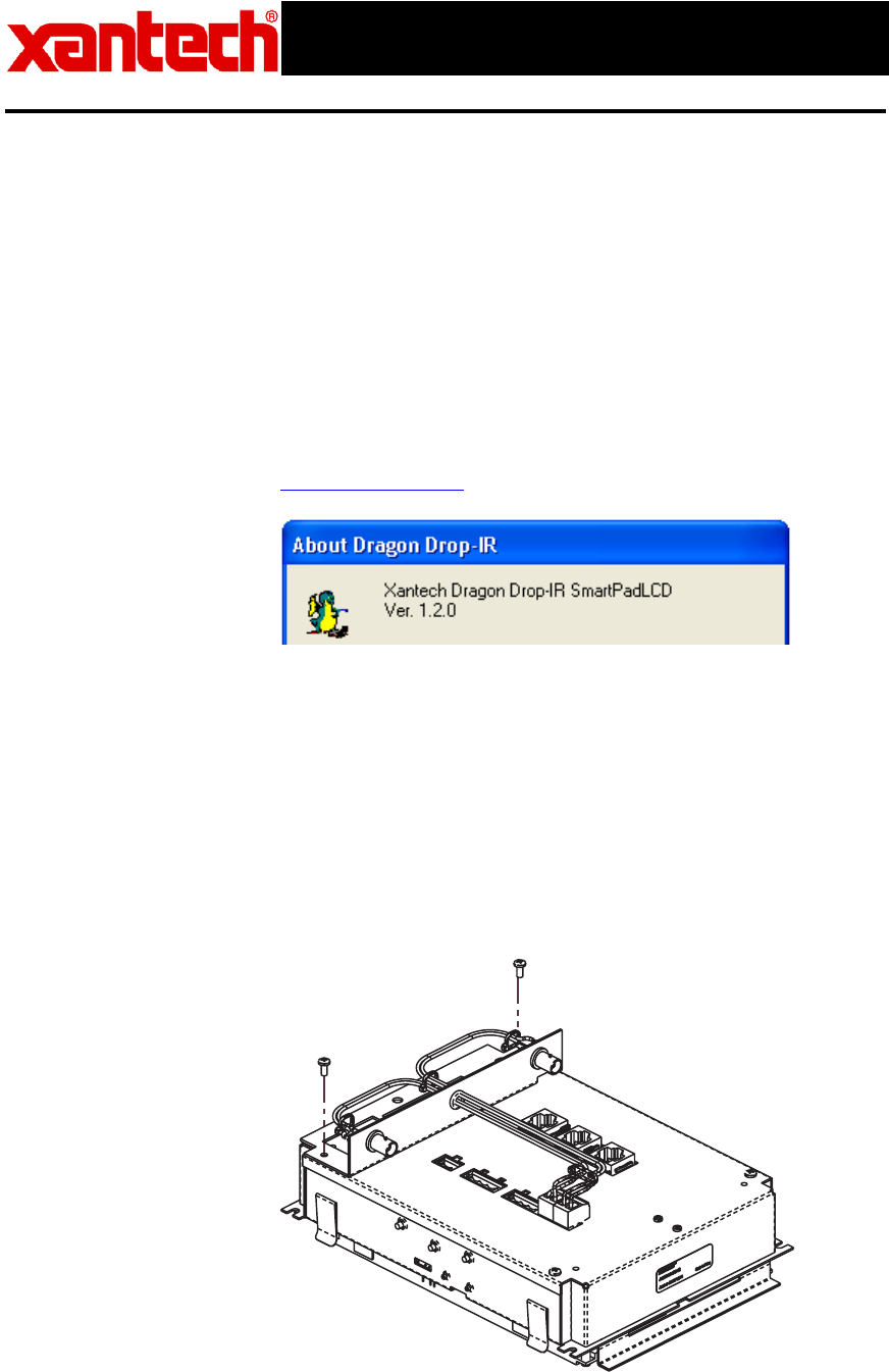
Checking Software
Version:
To check the software version, open Dragon Drop-IR (SPLCD) and
click on the HELP Menu and select ABOUT. The Software version
shall be noted at the top of the pop-up window. If it is not noted or
the version does not read 1.2.0 or higher, please see
www.xantech.com and download the latest version of Dragon Drop-
IR SPLCD.
Checking
FirmwareVersion:
To check the SPLCD64V for proper firmware version, connect the
panel to the PC running Dragon Drop-IR (SPLCD) and click on the
Base Unit Menu and select WHO AM I from the drop-down menu.
Video Connections:
Connect the composite video signal to the SPLCD 64V via the BNC
connection labeled VIDEO IN on the rear of the panel.
A buffered composite video signal can also be run OUT of the panel
to a main Video Monitor in the Zone if desired. To do this, connect a
coax cable to the BNC connection labeled VIDEO OUT on the rear of
the panel.
VIDEO BRACKET SUB-ASSEMBLY
MOUNTED ON LEFT SIDE (1ST OPTION)
VIDEO OUT
VIDEO IN
SmartPad LCD™ Touch Screen Controller
Advanced Feature Addendum
AA-11(SPLCD-ADDENDUM)
Page 2 of 2
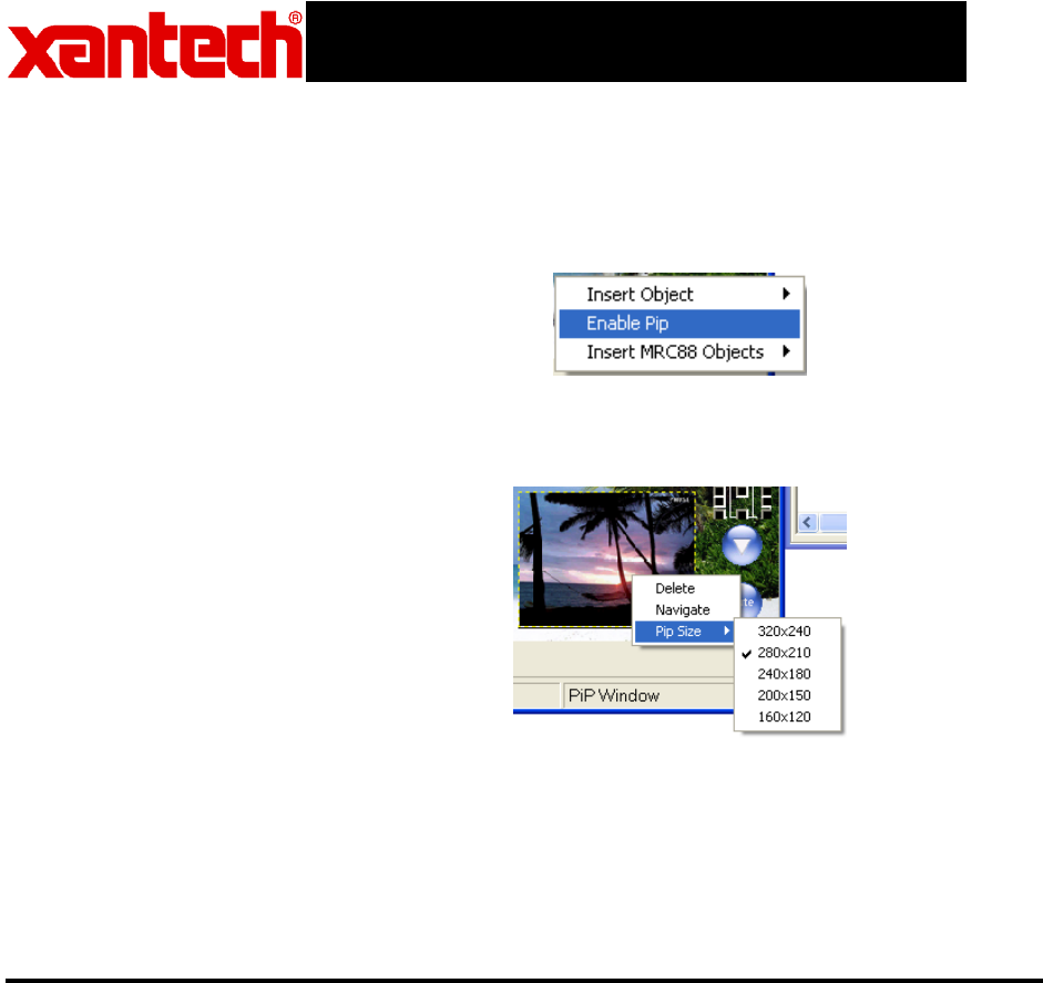
Picture-In-Picture
Mode (PiP):
A PiP window can be opened on any GTL (Graphical Touch Link) Page
desired. To enable a PiP:
1. Right-Click on a blank space and select Enable PiP from the
pop-up menu.
2. Click-&-Hold the PiP and Drag to the desired location on the
GTL page.
3. To resize the PiP, right-click on the PiP and select the desired
screen size.
Enabling Full-
Screen Video
Mode:
Once the project is downloaded to the SPLCD 64V base unit, the PiP
can be touched to enable Full Screen video mode.
To Return to PiP
Mode:
Simply touch the middle of the video screen to return back to PiP mode.
Transparent Button
GTL Overlay
Feature:
This feature allows for transparent ‘invisible’ button GTL to be placed on
the video screen during Full-Screen Video mode or any screen desired.
This is extremely useful for Music Server Control with feedback display
on units that output a Video Menu (theme) with buttons imbedded in the
video. This is also useful for hiding Volume UP & DOWN or Channel UP
& DOWN functionality to be available even when in Full-Screen Video
mode.
For Full Screen Transparent Button Overlay Functionality:
1. Right-click on the PiP screen and select NAVIGATE from the
pop-up menu.
Note: A Full Screen page will appear with a transparent button
object displayed in the middle. This object is the Return to PiP
button and cannot be removed. This button can be resized and
moved to any desired location.
2. To add a Transparent Button GTL simply right-click anywhere on
the blank area of the screen and select Insert Object from the
pop-up menu.

SmartPad LCD™ Touch Screen Controller
Advanced Feature Addendum
AA-11(SPLCD-ADDENDUM)
Page 3 of 3
3. Select Insert Transparent Button from the pop-up menu. A
Transparent Button will appear outlined on the screen.
4. Click-and-drag the button to the desired location (must be in
GRAPHICS Mode)
5. The button can be re-sized easily by clicking on one of the blue
squares outlining the button and dragging the square to the
desired size.
6. After all desired buttons are placed and sized appropriately on
the PiP Video screen, you can now assign IR and/or RS232
Macro’s to these buttons in the same manner as a standard
GTL. (I.e. Assign top right and bottom right buttons as Channel
UP/Down or Volume UP/DOWN.)
Transparent Button
GTL Music Server
Integration:
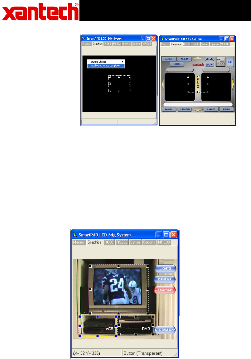
To interface to a Music Server Video Menu Screen (or any other
products Video Menu Screen), follow the steps below. If the product
interfacing to has a BMP (bitmap) file for reference, you can display this
image in the software and drag and drop transparent buttons over it for
seamless control of the device.:
1. Right-click on the PiP screen and select NAVIGATE from the
pop-up menu.
Note: A Full Screen page will appear with a transparent button
object displayed in the middle. This object is the Return to PiP
button and cannot be removed. This button can be resized and
moved to any desired location.
2. Right-Click anywhere on the blank area of the screen and select
Add Video Image Template from the pop-up menu.
Chan UP
Volume UP
Volume
Down
Chan Down
Exit
SmartPad LCD™ Touch Screen Controller
Advanced Feature Addendum
AA-11(SPLCD-ADDENDUM)
Page 4 of 4
3. Select the BMP image that represents the video menu to display.
4. Follow steps 3 thru 6 as displayed above to add Transparent
GTL’s to the template PiP and assign functionality to the GTL’s.
Other Uses for
Transparent GTL’s:
The transparent GTL feature is available for use on ALL versions of the
SmartPad LCD™ Controllers (SPLCD39G, 57G, 64G, and 64V).
Transparent GTL’s can be placed anywhere over an object such as a
picture used as a backdrop, Volume Bars etc…
See the example below illustrating how Transparent GTL buttons can be
placed over areas of a custom background for realistic visual
functionality:
Note: Please see section on IMPORTING BACKGROUNDS for
instructions. After the desired background is placed on the SmartPad
LCD™ Systems window, place Source buttons as you would normally

SmartPad LCD™ Touch Screen Controller
Advanced Feature Addendum
AA-11(SPLCD-ADDENDUM)
Page 5 of 5
and then follow the instructions below for adding Transparent Button
GTL’s:
1. To add a Transparent Button GTL simply right-click anywhere on
the blank area of the screen and select Insert Object from the
pop-up menu.
2. Select Insert Transparent Button from the pop-up menu. A
Transparent Button will appear outlined on the screen.
3. Click-and-drag the button to the desired location.
4. The button can be re-sized easily by clicking on one of the blue
squares outlining the button and dragging the square to the
desired size.
MRC88/SmartPad™
LCD Emulation
Mode:
The full line of SmartPad™ LCD Controllers can be seamlessly
integrated into a new or existing MRC88 System over the standard
CAT5 cable. This allows the SmartPad LCD™ Controller to access any
macro programmed in the MRC88 Controller without the use of IR
commands. All Macro Programming resides in the MRC88 allowing for
ease of initial programming and any upgrades that should occur.
Connecting the
SPLCD to the
MRC88 Controller:
1. Connect one end of the CAT5 to the Keypad port on the rear of
the MRC88 Controller and the other end to the Controller port
on the rear of the SPLCD Panel.
2. 16vDC Power must still be run directly to the +16VDC and GND
Terminals on the rear of the SPLCD panel.
Note: The SPLCD cannot be powered directly from the MRC88
Controller.
3. If using multiple keypads in a single Zone, the last keypad in line
must have the Zone Termination Jumper installed.
Note: The SPLCD comes with the Zone Termination Jumper
installed by default.
Configuring
Dragon Drop SPLCD
for MRC88
Emulation Mode:
1. Program the MRC88 as you would for a standard MRC88
Keypad using both the Tier1 and Tier2 of the buttons for added
functionality.
2. Create the graphic layout for an SPLCD project in Dragon as you
would normally.
3. After all of the GTL’s are layed out as in a standard SPLCD
project, click on the TAB labeled MRC88 in the SPLCD Systems
Window.
4. Check the box labeled Emulate MRC88 Keypad
5. If you are using Multiple Keypads in a single zone, set each
keypad to a unique Keypad Address. Up to four keypads can
be used together in a single zone. Note: If using standard
MRC88 Keypads in conjunction with the SPLCD in the Zone, you
must set the MRC88KP Address Jumper to the specific address.
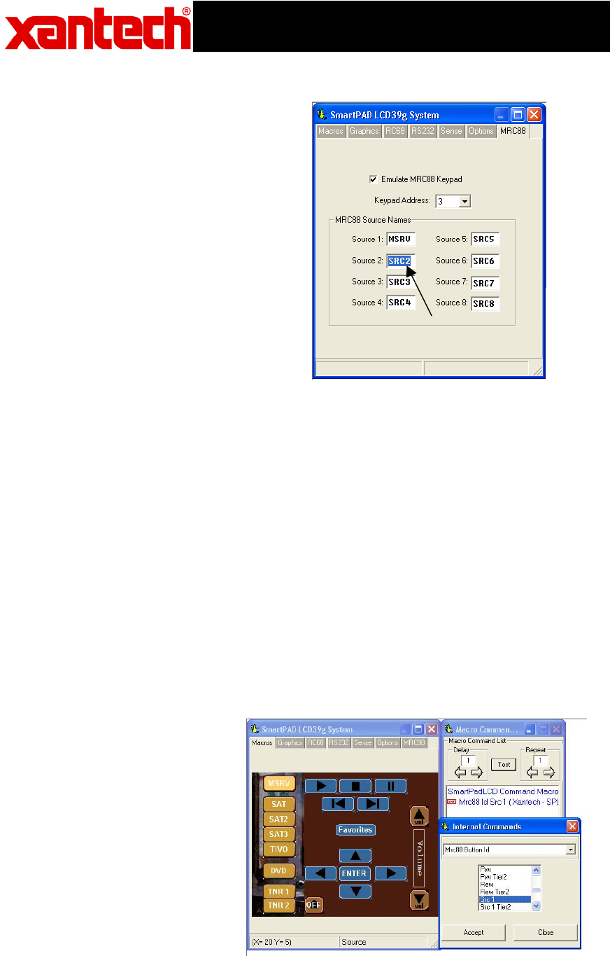
6. Under MRC88 Source Names enter the names as they appear
in the MRC88 Software. Note: This is necessary for proper
Source Name display when using the MRC88 STATUS function.
SmartPad LCD™ Touch Screen Controller
Advanced Feature Addendum
AA-11(SPLCD-ADDENDUM)
Page 6 of 6
Programming
SPLCD for MRC88
Functionality:
Once Dragon Drop SPLCD is configured for MRC88 Keypad
Emulation, you can now point each GTL on the SmartPad LCD™ to
a specific macro within the MRC88 Controller.
1. Click on the MACROs Tab to lock in the current GTL button
layout.
2. Select a Source Button in the SPLCD Systems Window.
3. Click on the PALETTES menu and select Internal Commands
from the drop-down menu.
4. Click on Backlight Set in the Internal Command Window and
select MRC88 Button Id from the drop-down menu.
These are pointers to buttons within the MRC88 Controller.
Whatever Macro is programmed within the MRC88 under these
buttons, the SPLCD can now execute these Macro’s.
5. Scroll through the list and associate SPLCD buttons to Macros
programmed under specific buttons within the MRC88 Controller.
i.e. Click on a Source Button and then select Src 1 from the
MRC88 Button Id list as in the example below.
Name Each Source
as it appears in the
DragMRC Project.

SmartPad LCD™ Touch Screen Controller
Advanced Feature Addendum
AA-11(SPLCD-ADDENDUM)
Page 7 of 7
6. Repeat above for all of the Source Buttons.
7. Repeat the same procedure for PLAY STOP PAUSE etc……
8. You can even assign SPLCD GTL Buttons to an MRC88 Tier 2
Macro. For example: Assign the 5 Motion control buttons to as
Tier 1 PLAY STOP PAUSE etc… In your MRC88 Project
program Tier 2 of the PLAY STOP PAUSE etc.. buttons as
MENU Navigation buttons and now select a SPLCD Button for
ENTER and assign it the PLAY TIER 2 Button Id.
9. Continue this for all buttons on the SPLCD (i.e. MRC88 Volume
Up, Down OFF MUTE etc….) that you want to control the
MRC88.
10. If more button control is needed from the SPLCD you can still
program standard buttons to pass IR through the CAT5 and
MRC88 Controller as you would in a standard project.
For Macro functionality, use RC68 IR Trigger codes within the
MRC88 Software. Therefore the SPLCD only needs to send a single
IR command to trigger a long macro within the MRC88. This keeps
all of the Macro programming within the MRC88.
Placing MRC88
Objects on the
SPLCD:
You can also place MRC88 graphic objects on the page. Objects
that can be displayed are as follows:
- STATUS Display: Displays Zone Status, Source Icons, and Zone
Linking information from the MRC88
- INFORMATION Display: Xantech XDT Tuner Feedback display,
MUTE and ZONE OFF status, Priority Lockout, etc.
- Horizontal Bars: Horizontal bar for Volume display or EQ/
Balance level display
- Vertical Bars: Vertical Bar for Volume display or EQ/Balance
display.
To display one or more of these objects,
1. Right-click on a blank area of the background.
2. Select Insert MRC88 Object from the drop-down menu.
3. Choose from Horizontal or Vertical Volume, EQ/Balance
bars, Informational Display, or Status Display.
Note: Once placed on the SPLCD Systems window, these objects can
be moved to any desired location and the border colors can be modified
to fit the desired style.
Horizontal and Vertical Bars can be resized for length and width.
STATUS and INFORMATION displays cannot be resized.
Tansparent GTL’s
and MRC88
Emulation:
Combining these two features allows for unique programming
possibilities.
Below is an example for creating Interactive Volume Bars so the user
can press different areas of the Volume bar and have the Zone Volume
Level jump immediately to that level. In this particular example we will
SmartPad LCD™ Touch Screen Controller
Advanced Feature Addendum
AA-11(SPLCD-ADDENDUM)
Page 8 of 8
separate the Volume Bar into three sections, Low Level, Mid Level and
High Volume Level.
This will require programming in both DragMRC and Dragon Drop-IR
SPLCD.
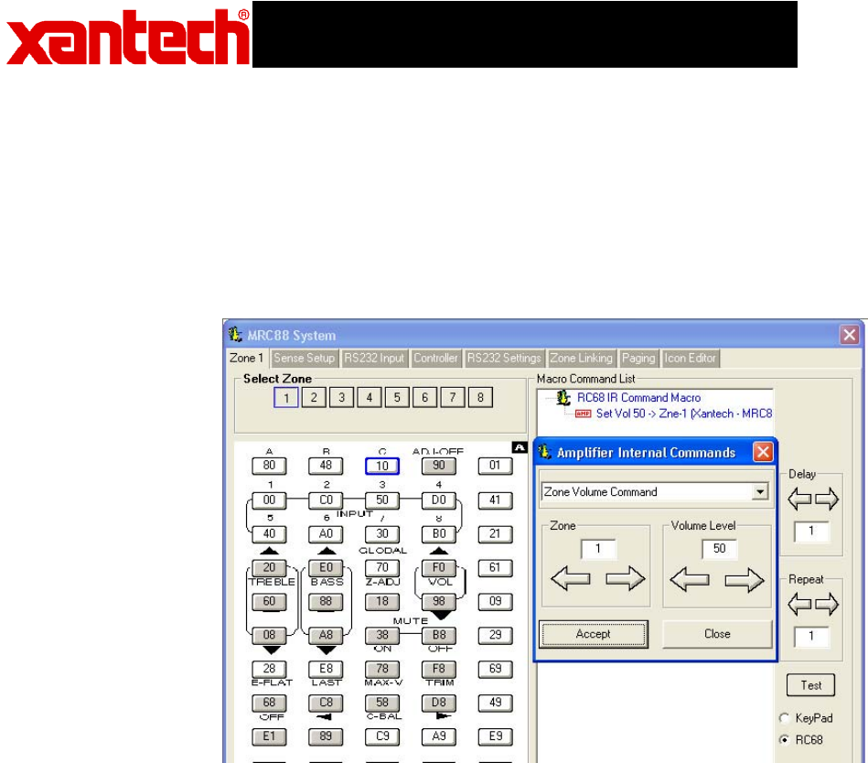
MRC88 Volume Level Programming:
(Refer to the MRC88 Manual; Section 5: RC68+ IR Code Triggered
Sequencer for further explanation of the following):
1. Within DragMRC Software, select the Zone Keypad the SPLCD will
be connected to.
2. Click on RC68 on the lower right of the MRC88 Systems Window
3. Click on Palette and select MRC Amplifier Command Generator.
4. Click on the Drop-Down arrow and select Zone Volume Command.
5. Select the Zone # (in this case Zone #1)
6. Select the [80] button on the Virtual RC68 (or any other free RC68
Trigger button).
7. Select a discrete Volume Level for the LOW setting (i.e. 20) and
select APPLY.
8. Repeat for two other RC68 trigger buttons for a Mid Volume level
and a Hi Volume Level (i.e. place discrete volume level 40 command
under button [48] and discrete Volume level 50 under button [10] on
the virtual RC68.
SmartPad LCD™ Touch Screen Controller
Advanced Feature Addendum
AA-11(SPLCD-ADDENDUM)
Page 9 of 9
Configuring SPLCD in Dragon Drop-IR SPLCD:
Placing the Volume Bar:
1. Right-click on a blank area of the background and select Insert
MRC88 Object from the drop-down menu.
2. Choose from Horizontal or Vertical Volume bar.
3. Place and resize to desired position.
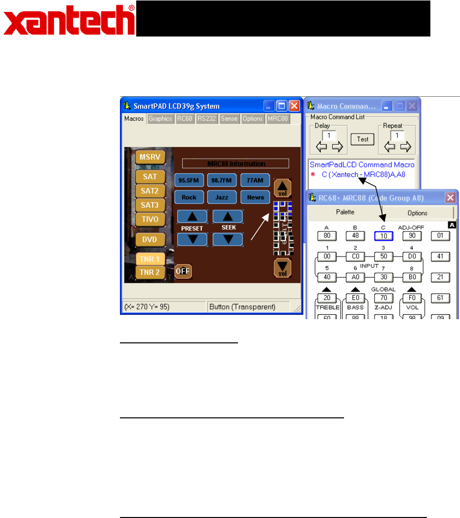
Creating Transparent GTL’s over Volume Bar:
1. Right-Click on a blank area of the background and select Insert
Object – Insert Transparent Button from the drop-down menu.
2. Resize the box to cover 1/3 of the volume bar and place over the
bottom 1/3 of the Volume Bar.
3. Place 2 more Transparent GTL boxes over the middle and upper 1/3
of the section of the Volume Bar
Assigning the Proper RC68 IR Codes to the Transparent GTL’s
1. Click on Palettes and select RC68 Command Palette from the menu.
2. Click on the OPTIONS Tab on the Virtual RC68 Palette and choose
MRC88 from the Xantech Model drop-down menu.
3. Click on the PALETTE Tab on the Virtual RC68
4. On the SPLCD Systems window, select the Transparent GTL placed
on the lower 1/3 of the Volume Bar.
5. Select the [80] button from the Virtual RC68 Palette (under the
Command List Window you should see the command ‘A(Xantech-
MRC88)A,A8’ )
6. Repeat steps 4 and 5 for the Middle and Hi level Transparent GTL
with the RC68 [48] and [10] commands as shown above.
Transparent GTL
placed over MRC88
Volume Bar
RC68 Trigger
Command
SmartPad LCD™ Touch Screen Controller
Advanced Feature Addendum
AA-11(SPLCD-ADDENDUM)
Page 10 of 10
Importing Pictures
as Custom
Backgrounds:
This is easiest performed on the SPLCD64G and SPLCD64V units due
to increased screen resolution (640x480).
Use the following guide lines when importing user-defined Bitmap
images,:
1. The image must be sized to 640x480 pixel resolution.
2. The image must be saved as a 16Bit 64k color Bitmap Image.
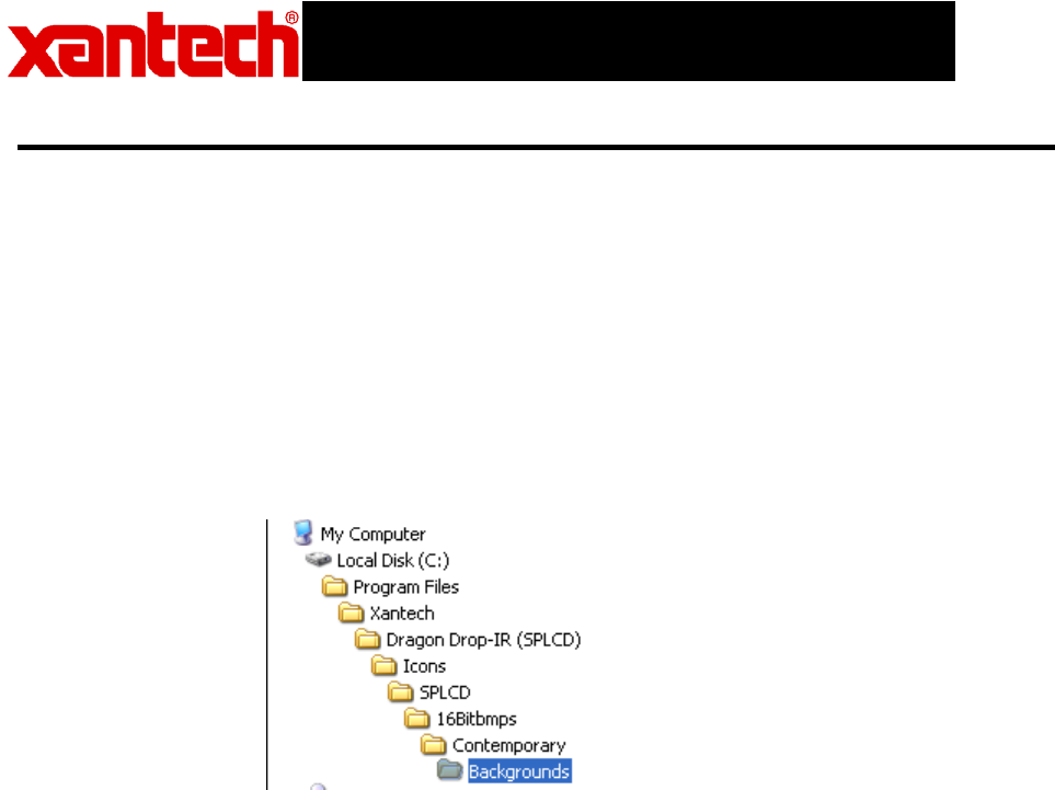
3. Place the image into the desired Style Background folder
Note: Background Style Directories are located at
C:\Program Files\Xantech\Dragon Drop-IR(SPLCD)\Icons\SPLCD folder
as shown below.
4. Re-start Dragon Drop-IR (SPLCD) software and select the Style
imported to and click on the Backgrounds folder and you should see
the imported background.
