2014 Prowler Service
User Manual: Manual
Open the PDF directly: View PDF ![]() .
.
Page Count: 218 [warning: Documents this large are best viewed by clicking the View PDF Link!]
- FRONT COVER
- FOREWORD
- TABLE OF CONTENTS
- General Information
- Periodic Maintenance
- SPECIAL TOOLS
- Periodic Maintenance Chart
- Lubrication Points
- Air Filter
- Valve/Tappet Clearance
- Testing Engine Compression
- Spark Plug(s)
- Muffler/Spark Arrester
- Engine/Transmission Oil - Filter
- Front Differential - Rear Drive Lubricant
- Driveshaft/Coupling
- Nuts/Bolts/Cap Screws
- Headlight/Taillight-Brakelight
- Shift Lever (XT/XTZ)
- Shift Lever/Shift Cable (XTX)
- Hydraulic Brake System
- Parking Brake (XT/XTZ)
- Burnishing Brake Pads
- Checking/Replacing V-Belt
- Steering/Frame/Controls
- Steering Assembly (XT)
- Electronic Power Steering (EPS) (XTX/XTZ)
- Steering Assembly (XTX/XTZ)
- Steering Wheel
- Upper Steering Shaft
- Lower Steering Shaft Assembly
- Steering Knuckles
- Checking/Adjusting Front Wheel Alignment
- Front Bumper Assembly
- Hood
- Fenders
- Floor
- Belly Panel
- Accelerator Pedal
- Shift Lever (XT/XTZ)
- Shift Lever (XTX)
- LCD Gauge/Indicator Lights
- Exhaust System
- Cargo Box
- Taillight Assembly
- Seats
- Troubleshooting
- Engine/Transmission
- SPECIAL TOOLS
- Troubleshooting
- Prowler XT/XTX (Table of Contents)
- Removing Engine/ Transmission
- Top-Side Components
- Removing Top-Side Components
- Servicing Top-Side Components
- VALVE ASSEMBLY
- Cleaning/Inspecting Valve Cover
- Removing Valves
- Measuring Valve Stem Runout
- Measuring Valve Stem Outside Diameter
- Measuring Valve Face/Seat Width
- Measuring Valve Face Radial Runout
- Measuring Valve Guide/Valve Stem Deflection (Wobble Method)
- Measuring Valve Guide (Inside Diameter)
- Servicing Valves/Valve Guides/Valve Seats
- Measuring Rocker Arm (Inside Diameter)
- Measuring Rocker Arm Shaft (Outside Diameter)
- Installing Valves
- PISTON ASSEMBLY
- Cleaning/Inspecting Piston
- Removing Piston Rings
- Cleaning/Inspecting Piston Rings
- Measuring Piston-Ring End Gap (Installed)
- Measuring Piston Pin (Outside Diameter) and Piston-Pin Bore
- Measuring Piston Skirt/Cylinder Clearance
- Installing Piston Rings
- CYLINDER/CYLINDER HEAD ASSEMBLY
- Cleaning/Inspecting Cylinder Head
- Measuring Cylinder Head Distortion
- Cleaning/Inspecting Cylinder
- Inspecting Cam Chain Guide
- Inspecting Cylinder
- Measuring Camshaft Runout
- Measuring Camshaft Lobe Height
- Inspecting Camshaft Bearing Journal
- Measuring Camshaft to Cylinder Head Clearance
- Inspecting Camshaft Spring/Drive Pin
- Installing Top-Side Components
- Right-Side Components
- Removing Right-Side Components
- Servicing Right-Side Components
- Installing Right-Side Components
- Left-Side Components
- Removing Left-Side Components
- Servicing Left-Side Components
- Installing Left-Side Components
- Center Crankcase Components
- Separating Crankcase Halves
- Disassembling Crankcase Half
- Servicing Center Crankcase Components
- SECONDARY OUTPUT DRIVE GEARS
- Initial Set-Up
- Checking Backlash
- Correcting Backlash
- CRANKSHAFT ASSEMBLY
- Measuring Connecting Rod (Small End Inside Diameter)
- Measuring Connecting Rod (Small End Deflection)
- Measuring Connecting Rod (Big End Side-to-Side)
- Measuring Crankshaft (Runout)
- Measuring Crankshaft (Web-to-Web)
- COUNTERSHAFT
- Disassembling
- Assembling
- Assembling Crankcase Half
- Joining Crankcase Halves
- Installing Engine/Transmission
- Prowler XTZ (Table of Contents)
- Removing Engine/Transmission
- Top-Side Components
- Removing Top-Side Components
- Servicing Top-Side Components
- VALVE ASSEMBLY
- Cleaning/Inspecting Valve Cover
- Removing Valves
- Measuring Valve Stem Runout
- Measuring Valve Stem Outside Diameter
- Measuring Valve Face/Seat Width
- Measuring Valve Face Radial Runout
- Measuring Valve Guide/Valve Stem Deflection (Wobble Method)
- Measuring Valve Guide (Inside Diameter)
- Servicing Valves/Valve Guides/Valve Seats
- Measuring Rocker Arm (Inside Diameter)
- Measuring Rocker Arm Shaft (Outside Diameter)
- Installing Valves
- PISTON ASSEMBLY
- Removing Piston Rings
- Cleaning/Inspecting Piston
- Measuring Piston-Ring End Gap (Installed)
- Measuring Piston Pin (Outside Diameter) and Piston-Pin Bore
- Measuring Piston Skirt/Cylinder Clearance
- Installing Piston Rings
- CYLINDER/CYLINDER HEAD ASSEMBLY
- Cleaning/Inspecting Cylinder Head
- Measuring Cylinder Head Distortion
- Cleaning/Inspecting Cylinder
- Inspecting Cam Chain Guide
- Measuring Camshaft Runout
- Measuring Camshaft Lobe Height
- Inspecting Camshaft Bearing Journal
- Measuring Camshaft to Cylinder Head Clearance
- Inspecting Camshaft Spring/Drive Pin (Front Camshaft Only)
- Installing Top-Side Components
- Left-Side Components
- Removing Left-Side Components
- Servicing Left-Side Components
- Installing Left-Side Components
- Right-Side Components
- Removing Right-Side Components
- Servicing Right-Side Components
- Installing Right-Side Components
- Center Crankcase Components
- Separating Crankcase Halves
- Disassembling Crankcase Half
- Servicing Center Crankcase Components
- SECONDARY OUTPUT DRIVE GEARS
- Initial Set-Up
- Checking Backlash
- Correcting Backlash
- OIL PUMP ASSEMBLY
- Disassembling and Inspecting
- Assembling
- CRANKSHAFT ASSEMBLY
- Measuring Connecting Rod (Small End Inside Diameter)
- Measuring Connecting Rod (Small End Deflection)
- Measuring Connecting Rod (Big End Side-to-Side)
- Measuring Crankshaft (Runout)
- Measuring Crankshaft (Web-to-Web)
- COUNTERSHAFT
- Disassembling
- Assembling
- Assembling Crankcase Half
- Joining Crankcase Halves
- Installing Engine/Transmission
- Fuel/Lubrication/Cooling
- Electrical System
- SPECIAL TOOLS
- TESTING ELECTRICAL COMPONENTS
- ELECTRICAL CONNECTIONS
- Battery
- RPM Limiter
- Switches
- Accessory Receptacle/Connector
- Brakelight Switch
- Engine Coolant Temperature (ECT) Sensor
- Fan Motor
- Power Distribution Module (PDM)
- Ignition Coil
- EFI Sensors/Components
- Speed Sensor
- Electronic Power Steering (EPS) (XTZ)
- Electronic Power Steering (EPS) (XTX)
- Ignition Switch
- Headlight Switch
- Drive Select Switch
- Reverse Override Switch
- Front Drive Actuator
- Stator Coil/Crankshaft Position (CKP) Sensor
- Starter Motor
- Starter Relay
- Electronic Control Unit (ECM)
- Regulator/Rectifier
- Headlights
- Taillight-Brakelight
- Ignition Timing
- Tilt Sensor
- Throttle Position Sensor (TPS)
- ECM Error Codes (XT/XTZ)
- EFI Diagnostic System (XTX)
- DIGITAL GAUGE
- Coolant (COOL) Diagnostic Mode
- Fuel Sensor (FUEL) Diagnostic Mode
- Tachometer (tACH) Diagnostic Mode
- Speed (SPd) Diagnostic Mode
- TPS (tPS) Diagnostic Mode
- MAP (bArO) Diagnostic Mode
- Inlet Air Temperature (AIr) Diagnostic Mode
- Battery (bAtt) Diagnostic Mode
- DIAGNOSTIC TROUBLE CODES (DTC)
- Code List
- Troubleshooting
- Drive System
- GENERAL INFORMATION
- SPECIAL TOOLS
- Front Drive Actuator
- Front Differential
- REMOVING
- Disassembling Input Shaft
- Assembling Input Shaft
- Disassembling Differential Assembly
- Disassembling Pinion Gear
- Assembling Pinion Gear
- Shimming Procedure/Shim Selection
- Backlash
- Ring Gear End-Play
- RING GEAR/THRUST BUTTON
- Removing
- Inspecting
- Installing/Shimming
- Assembling Differential Assembly
- Removing/Installing Axle Seal
- INSTALLING DIFFERENTIAL
- Drive Axles
- Rear Gear Case
- Hub
- Hydraulic Brake Caliper
- Universal Joints (XTZ)
- Troubleshooting Drive System
- Troubleshooting Brake System
- Suspension
- BACK COVER

PROWLER XT/XTX/XTZ
[ROV]
SERVICE MANUAL
2014

FOREWORD
This Arctic Cat Service Manual contains service, maintenance, and troubleshooting information for certain 2014 Arctic
Cat ROV (Recreational Off-Highway Vehicle) models (see cover). The complete manual is designed to aid service per-
sonnel in service-oriented applications.
This manual is divided into sections. Each section covers a specific vehicle component or system and, in addition to the
standard service procedures, includes disassembling, inspecting, and assembling instructions. When using this manual
as a guide, the technician should use discretion as to how much disassembly is needed to correct any given condition.
This service manual is designed primarily for use by an Arctic Cat CatMaster Basic Level technician. The procedures
found in this manual are of varying difficulty, and certain service procedures in this manual require one or more special
tools to be completed. The technician should use sound judgement when determining which procedures can be com-
pleted based on their skill level and access to appropriate special tools.
All Arctic Cat publications and decals display the words Warning, Caution, Note, and At This Point to emphasize
important information. The symbol ! WARNING identifies personal safety-related information. Be sure to fol-
low the directive because it deals with the possibility of serious personal injury or even death. A CAUTION identi-
fies unsafe practices which may result in vehicle-related damage. Follow the directive because it deals with the
possibility of damaging part or parts of the vehicle. The symbol NOTE: identifies supplementary information wor-
thy of particular attention. The symbol AT THIS POINT directs the technician to certain and specific proce-
dures to promote efficiency and to improve clarity.
At the time of publication, all information, photographs, and illustrations were technically correct. Some photographs
used in this manual are used for clarity purposes only and are not designed to depict actual conditions. Because Arctic
Cat Inc. constantly refines and improves its products, no retroactive obligation is incurred.
All materials and specifications are subject to change without notice.
Keep this manual accessible in the shop area for reference.
Product Service and
Warranty Department
Arctic Cat Inc.
© 2013 Arctic Cat Inc. November 2013
®™ Trademarks of Arctic Cat Inc., Thief River Falls, MN 56701
1
TABLE OF CONTENTS
General Information...................................................... 2
General Specifications ...................................................... 2
Torque Specifications........................................................ 3
Torque Conversions (ft-lb/N-m) ......................................... 4
Gasoline - Oil - Lubricant .................................................. 4
Genuine Parts ................................................................... 5
Preparation For Storage.................................................... 5
Preparation After Storage ................................................. 6
Periodic Maintenance ................................................... 7
Periodic Maintenance Chart.............................................. 7
Lubrication Points.............................................................. 8
Air Filter............................................................................. 8
Valve/Tappet Clearance .................................................... 8
Testing Engine Compression ............................................ 9
Spark Plug(s) .................................................................. 10
Muffler/Spark Arrester..................................................... 10
Engine/Transmission Oil - Filter ...................................... 11
Front Differential - Rear Drive Lubricant ......................... 12
Driveshaft/Coupling......................................................... 12
Nuts/Bolts/Cap Screws ................................................... 12
Headlight/Taillight-Brakelight........................................... 13
Shift Lever (XT/XTZ) ....................................................... 13
Shift Lever/Shift Cable (XTX) .......................................... 14
Hydraulic Brake System.................................................. 15
Parking Brake (XT/XTZ).................................................. 16
Burnishing Brake Pads.................................................... 19
Checking/Replacing V-Belt.............................................. 19
Steering/Frame/Controls ............................................ 21
Steering Assembly (XT) .................................................. 21
Electronic Power Steering (EPS) (XTX/XTZ) .................. 23
Steering Assembly (XTX/XTZ)........................................ 26
Steering Wheel ............................................................... 27
Upper Steering Shaft ...................................................... 28
Lower Steering Shaft Assembly ...................................... 29
Steering Knuckles ........................................................... 30
Checking/Adjusting Front Wheel Alignment.................... 32
Front Bumper Assembly.................................................. 33
Hood ............................................................................... 33
Fenders........................................................................... 34
Floor................................................................................ 34
Belly Panel ...................................................................... 35
Accelerator Pedal............................................................ 35
Shift Lever (XT/XTZ) ....................................................... 35
Shift Lever (XTX)............................................................. 36
LCD Gauge/Indicator Lights............................................ 36
Exhaust System .............................................................. 37
Cargo Box ....................................................................... 37
Taillight Assembly............................................................ 38
Seats............................................................................... 38
Troubleshooting............................................................... 38
Engine/Transmission.................................................. 40
Troubleshooting............................................................... 41
Prowler XT/XTX (Table of Contents) ............................... 43
Prowler XTZ (Table of Contents)..................................... 88
Fuel/Lubrication/Cooling.......................................... 144
Electronic Fuel Injection (XT/XTX)................................ 144
Electronic Fuel Injection (XTZ)...................................... 145
Gas Tank....................................................................... 146
Gas/Vent Hoses ............................................................ 149
Oil Filter/Oil Pump......................................................... 149
Oil Cooler (XTZ)............................................................ 150
Liquid Cooling System...................................................151
Radiator .........................................................................151
Thermostat (XT/XTX) ....................................................152
Thermostat (XTZ) ..........................................................153
Fan.................................................................................153
Water Pump (XT/XTX)...................................................153
Water Pump (XTZ).........................................................154
Electric Fuel Pump/Fuel Level Sensor...........................155
Troubleshooting .............................................................157
Electrical System ......................................................158
Battery ...........................................................................158
RPM Limiter...................................................................159
Switches ........................................................................159
Accessory Receptacle/Connector .................................159
Brakelight Switch ...........................................................160
Engine Coolant Temperature (ECT) Sensor..................160
Fan Motor ......................................................................160
Power Distribution Module (PDM)..................................161
Ignition Coil....................................................................162
EFI Sensors/Components .............................................162
Speed Sensor................................................................163
Electronic Power Steering (EPS) (XTZ).........................164
Electronic Power Steering (EPS) (XTX) ........................165
Ignition Switch ...............................................................167
Headlight Switch............................................................167
Drive Select Switch........................................................167
Reverse Override Switch ...............................................168
Front Drive Actuator.......................................................168
Stator Coil/Crankshaft Position (CKP) Sensor...............168
Starter Motor .................................................................169
Starter Relay..................................................................170
Electronic Control Unit (ECM) .......................................170
Regulator/Rectifier.........................................................171
Headlights......................................................................171
Taillight-Brakelight..........................................................171
Ignition Timing ...............................................................171
Tilt Sensor .....................................................................172
Throttle Position Sensor (TPS) ......................................173
ECM Error Codes (XT/XTZ) ..........................................174
EFI Diagnostic System (XTX)........................................174
Troubleshooting .............................................................179
Drive System .............................................................181
Front Drive Actuator.......................................................181
Front Differential ............................................................182
Drive Axles ....................................................................194
Rear Gear Case ............................................................197
Hub ................................................................................200
Hydraulic Brake Caliper .................................................202
Universal Joints (XTZ) ...................................................205
Troubleshooting Drive System.......................................208
Troubleshooting Brake System ......................................208
Suspension................................................................209
Shock Absorbers ...........................................................209
Front A-Arms .................................................................210
Rear A-Arms..................................................................212
Wheels and Tires...........................................................213
Troubleshooting .............................................................214

2
General Information
NOTE: Some photographs and illustrations used in
this section are used for clarity purposes only and
are not designed to depict actual conditions.
NOTE: Whenever a part is worn excessively,
cracked, or damaged in any way, replacement is nec-
essary.
General Specifications
* Visible at plug threads.
Specifications subject to change without notice.
CHASSIS
Dry Weight (approx) 558 kg (1230 lb) - XT
567 kg (1251 lb) - XTX
596 kg (1315 lb) - XTZ
ROPS Tested Curb Weight 645 kg (1428 lb)
Length (overall) 301.5 cm (118.7 in.)
Height (overall) 201 cm (79 in.)
Width (overall) 156.2 cm (61.5 in.)
Tire Size (XT/XTX) 26 x 9R-14 (front)
26 x 11R-14 (rear)
Tire Size (XTZ) 27 x 9R-14 (front)
27 x 11R-14 (rear)
Tire Inflation Pressure 0.84-1.41 kg/cm² (12-20 psi)
MISCELLANY
Spark Plug Type NGK CPR8E
Spark Plug Gap 0.5-0.6 mm (0.019-0.024
in.)
Gas Tank Capacity 31 L (8.2 U.S. gal.)
Coolant Capacity 2.9 L (3.0 U.S. qt) - XT/XTX
3.3 L (3.5 U.S. qt) - XTZ
Front Differential Capacity 275 ml (9.3 fl oz)*
Rear Drive Capacity 250 ml (8.5 fl oz)*
Engine Oil Capacity 2.5 L (2.6 U.S. qt) - Over-
haul
1.9 L (2.0 U.S. qt) - Change
Gasoline (recommended) 87 Octane Regular
Unleaded
Engine Oil (recommended) Arctic Cat ACX All Weather
Synthetic
Front Differential/Rear Drive Lubricant SAE Approved 80W-90
Hypoid
Belt Width 35.0 mm (1.38 in.)
Brake Fluid DOT 4
Taillight/Brakelight 12V/8W/27W
Headlight 12V/27W (4)
ELECTRICAL SYSTEM
Spark Plug Cap 5000 ohms
Ignition Coil Resistance (primary)
(secondary)
Less than 1 ohm - XT/XTX
4.8 ohms - XTZ
12k-19k ohms
Ignition Coil Primary Voltage Battery Voltage
Stator Coil (crankshaft position sensor)
Resistance (AC generator)
150-250 ohms
Less than 1 ohm
Crankshaft Position Sensor AC Voltage 2.0 or more
AC Generator Output (no load) 60 AC volts @ 5000 RPM -
XT/XTX
75 AC volts @ 5000 RPM -
XTZ
Ignition Timing 10° BTDC @ 1500 RPM
VALVES AND GUIDES
Valve Face Diameter 31.6 mm - intake
27.9 mm - exhaust
Valve/Tappet Clearance (cold engine)
(max)
0.1016 mm - intake
0.1524 mm - exhaust
Valve Guide/Stem Clearance (max) 0.013 mm
Valve Guide/Valve Stem Deflection (wob-
ble method) (max)
0.35 mm
Valve Guide Inside Diameter 5.000-5.012 mm
Valve Stem Outside Diameter 4.972-4.987 mm
Valve Stem Runout (max) 0.1 mm
Valve Head Thickness (min) 2.3 mm
Valve Face/Seat Width 2.25 mm - intake
2.60 mm - exhaust
Valve Seat Angle 45° +15’/+30’
Valve Face Radial Runout (max) 0.2 mm
Valve Spring Free Length (min) 38.7 mm
Valve Spring Tension @ 31.5 mm 19.0 kg (42 lb)
CAMSHAFT AND CYLINDER HEAD
Cam Lobe Height (min) (Ex/In)
(Ex)
(In)
33.60 mm - XT/XTX
33.40 mm - XTZ
33.53 mm - XTZ
Camshaft Journal Oil Clearance (max) 0.04 mm
Camshaft Journal (right & center)
Holder Inside Diameter (left)
21.98-22.04 mm
17.48-17.53 mm
Camshaft Journal (right & center)
Outside Diameter
(left)
21.96-21.98 mm - XT/XTX
21-94-21.98 - XTZ
17.48-17.53 mm - XT/XTX
17.44-17.48 - XTZ
Camshaft Runout (max) 0.05 mm
Rocker Arm Inside Diameter (max) 12.018 mm
Rocker Arm Shaft Outside Diameter (min) 11.97 mm
Cylinder Head/Cover Distortion (max) 0.05 mm
CYLINDER, PISTON, AND RINGS
Piston Skirt/Cylinder Clearance 0.025-0.075 mm
Cylinder Bore 91.995-92.005 mm - XT
101.992-102.008 mm - XTX
91.992-92.008 mm - XTZ
Piston Diameter 15 mm from Skirt End 92.940-92.975 mm - XT/XTZ
101.940-101.985 mm - XTX
Piston Ring Free End Gap (min) (1st/2nd)12.5 mm
Bore x Stroke 92 x 82 mm - XT
102 x 85 mm - XTX
92 x 71.6 mm - XTZ
Cylinder Trueness (max) 0.02 mm
Piston Ring End Gap - Installed 0.38 mm
Piston Ring to Groove Clearance (max) 0.35 mm
Piston Ring Groove Width (1st/2nd)
(oil)
1.202-1.204 mm
2.01-2.03 mm - XT/XTX
2.501-2.503 mm - XTZ
Piston Ring Thickness (1st/2nd) 1.970-1.990 mm - XT/XTX
1.170-1.195 mm - XTZ
Piston Pin Bore (max) 20.012 mm
Piston Pin Outside Diameter (min) 22.99 mm - XT/XTX
19.995 mm - XTZ
CRANKSHAFT
Connecting Rod (small end inside diame-
ter) (max)
23.021 mm - XT/XTX
20.021 mm - XTZ
Connecting Rod (big end side-to-side) 0.6 mm - XT/XTX
0.95 mm - XTZ
Connecting Rod (small end deflection)
(max)
0.3 mm
Crankshaft (web-to-web) 71 mm - XT/XTX
98 mm - XTZ
Crankshaft Runout (max) 0.03 mm
Oil Pump Gerotor Clearance (XTZ) (max) 0.15 mm

3
Torque Specifications
NOTE: Torque specifications have the following tolerances:
* w/Red Loctite #271 ** w/Green Loctite #609
*** w/“Patch-Lock”
Torque (ft-lb) Tolerance
0-15 ±20%
16-39 ±15%
40+ ±10%
EXHAUST COMPONENTS
Part Part Bolted To Torque
ft-lb N-m
Exhaust Pipe Cylinder Head 20 27
O2 Sensor Exhaust Pipe 19 26
Spark Arrester Muffler 48
in.-lb
5
BRAKE COMPONENTS
Brake Disc* Hub 15 20
Brake Hose Caliper 20 27
Brake Hose Master Cylinder 20 27
Master Cylinder Frame 25 34
Caliper Holder*** Knuckle 20 27
Brake Caliper*** Gear Case Housing 20 27
Brake Caliper Rear Drive Housing 20 27
Parking Brake Actuator Lever Caliper 20 27
Parking Brake Caliper Assembly Rear Drive Housing 20 27
SUSPENSION COMPONENTS (Front)
Upper A-Arm (XTZ) Frame 40 54
Upper A-Arm (XT/XTX) Frame 35 48
Knuckle Ball Joint 35 48
Shock Absorber Frame/Upper A-Arm 35 48
Lower A-Arm Frame 35 48
SUSPENSION COMPONENTS (Rear)
Sway Bar Bracket (XTZ) Frame 35 48
Sway Bar Bracket (XT/XTX) Frame 33 45
A-Arm Frame 35 48
Shock Absorber (Lower)
(XT/XTX)
Lower A-Arm 20 27
Shock Absorber (Lower) (XTZ) Lower A-Arm 35 48
Shock Absorber (Upper) Frame 35 48
Knuckle A-Arm 35 48
STEERING COMPONENTS
Steering Wheel* Upper Steering Shaft 25 34
Steering Wheel Shaft** Intermediate Shaft 36 49
Rack and Pinion Assembly (XT) Frame 50 68
Rack and Pinion Assembly
(XTX/XTZ)
Frame 35 48
Tie Rod* (XT) Rack 52 70
Tie Rod* (XTX/XTZ) Rack 37 50
Tie Rod End** Knuckle 30 41
Jam Nut Tie Rod End 10 14
EPS Assembly (XTX/XTZ) Frame 35 48
EPS Assembly (XTX/XTZ) Rack Coupler 11 15
EPS Cradle Bracket Knuckle 20 27
Intermediate Shaft Coupler Intermediate Shaft 31 42
Intermediate Shaft** (XT) Steering Pinion Shaft 36 49
Intermediate Shaft (XTX/XTZ) EPS Input Shaft 11 15
Steering Shaft Housing (6 mm)
(XTX/XTZ)
Frame 811
Steering Shaft Housing (8 mm)
(XTX/XTZ)
Frame 20 27
CHASSIS/ROPS ASSEMBLY
Part Part Bolted To Torque
ft-lb N-m
Front Bumper Frame 35 48
Front/Rear ROPS Tube* Arm Rest/Steering Sup-
port
25 34
Rear ROPS Tube ROPS Support 35 48
Top ROPS Support Front/Rear ROPS Tubes 35 48
Rear ROPS Tube Lower ROPS Support 35 48
Cargo Box Hinge Cargo Box Frame 20 27
Cargo Box Cargo Box Frame 20 27
Latch Pivot Bushing Cargo Box Frame 15 20
Latch Striker Cargo Box Liner 60
in.-lb
7
DRIVE TRAIN COMPONENTS
Rear Gear Case Frame 38 48
Drive Coupler (Front) Drive Flange 40 54
Driveline Rear Drive Input Flange 20 27
Front Differential Frame/Differential Bracket 38 52
Rear Output Flange Rear U-Joint Flange 40 54
Input Shaft Assembly Gear Case Housing 23 31
Pinion Housing Differential Housing 23 31
Thrust Button Gear Case Cover 811
Differential Housing Cover** Differential Housing 23 31
Drive Bevel Gear Nut** Shaft 87 118
Lock Collar Differential Housing 125 170
Hub Axle (min) 200 272
Oil Drain Plug Front Differential - Rear
Drive
45
in.-lb
5
Oil Fill Plug Front Differential - Rear
Drive
16 22
Wheel (Aluminum) Hub 80 108
Wheel (Steel) Hub 45 61
Front Input Drive Flange Front U-Joint 20 27
ENGINE/TRANSMISSION
Clutch Shoe* Crankshaft 221 300
Clutch Cover/Housing Assem-
bly
Crankcase 9.5 13
Cylinder Head Nut (6 mm) Cylinder 8.5 11.5
Cylinder Head Nut (8 mm) Cylinder 21 28.5
Valve Cover Cylinder Head 8.5 11.5
Driven Pulley Bolt (XT) Driveshaft 60 81
Driven Pulley Nut* (XTX/XTZ) Driveshaft 162 220
Movable Drive Face Nut* Driveshaft 165 224
Ground Wire Engine 811
Coil Frame 811
Magneto Cover Crankcase 9.5 13
Tappet Cover Valve Cover 8.5 11.5
Crankshaft Spacer Crankshaft 28 38
Oil Pump Cover* Crankcase 8.5 11.5
Outer Magneto Cover Magneto Cover 10 14
Cam Sprocket Camshaft 10 14
Speed Sensor Housing Crankcase 8.5 11.5
V-Belt Cover Crankcase 10 14
Oil Drain Plug Engine 16 27
Shift Lever Shift Axle Bracket 20 27
Intake Boot Clamp Intake Boot 30
in.-lb
3.4
Oil Pump Drive Gear* Crank Balancer Shaft 63 85
Starter Motor Crankcase 10 14
Output Yoke Nut* Output Shaft 200 270
Starter One-Way Clutch* Flywheel 26 35
Front Engine Mounting Bracket Frame 45 61
Rear Engine Mounting Bracket Frame 45 61
Engine Mounting Through-Bolt Frame 40 54
4
* w/Red Loctite #271 ** w/Green Loctite #609
Torque Conversions
(ft-lb/N-m)
Gasoline - Oil - Lubricant
RECOMMENDED GASOLINE
The recommended gasoline to use is 87 minimum octane
regular unleaded. In many areas, oxygenates are added to
the gasoline. Oxygenated gasolines containing up to 10%
ethanol or 5% methane.
When using ethanol blended gasoline, it is not necessary
to add a gasoline antifreeze since ethanol will prevent the
accumulation of moisture in the fuel system.
ENGINE/TRANSMISSION - XT/XTX
Part Part Bolted To Torque
ft-lb N-m
Crankcase Half (6 mm) Crankcase Half 10 14
Crankcase Half (8 mm) Crankcase Half 21 28
Cylinder Head (Cap Screw) Crankcase 37 50
Output Shaft Flange Nut* Output Shaft 62 84
Magneto Rotor Nut* Crankshaft 107 145
Output Shaft Nut* Output Shaft 59 80
Secondary Shaft Bearing
Housing
Crankcase Half 28 38
Stator Coil Magneto Cover 11 15
ENGINE/TRANSMISSION - XTZ
Lower Crankcase Cover (6
mm)
Crankcase 811
Lower Crankcase Cover (8
mm)
Crankcase 20 27
Crankcase Half Crankcase Half 811
Cylinder Head (Cap Screw) Crankcase 38 52
Rotor/Flywheel Nut* Crankshaft 105 143
CVT Cover Crankcase 811
Secondary Drive Gear Nut* Secondary Drive Output
Shaft
74 100
Oil Filter Cover Crankcase 811
Shift Cam Stopper Crankcase 811
Shift Cam Stopper Spring Shift Cam Stopper 811
Shift Cam Plate Shift Cam Shaft 811
Shifter Housing Crankcase 811
Oil Strainer Cap Crankcase 811
Stator Coil Magneto Cover (New) 13 18
Stator Coil Magneto Cover (Existing) 11 15
ft-lb N-m ft-lb N-m ft-lb N-m ft-lb N-m
11.4 26 35.4 51 69.4 76 103.4
22.7 27 36.7 52 70.7 77 104.7
34.1 28 38.1 53 72.1 78 106.1
45.4 29 39.4 54 73.4 79 107.4
56.8 30 40.8 55 74.8 80 108.8
68.2 31 42.2 56 76.2 81 110.2
79.5 32 43.5 57 77.5 82 111.5
810.9 33 44.9 58 78.9 83 112.9
912.2 34 46.2 59 80.2 84 114.2
10 13.6 35 47.6 60 81.6 85 115.6
11 15 36 49 61 83 86 117
12 16.3 37 50.3 62 84.3 87 118.3
13 17.7 38 51.7 63 85.7 88 119.7
14 19 39 53 64 87 89 121
15 20.4 40 54.4 65 88.4 90 122.4
16 21.8 41 55.8 66 89.8 91 123.8
17 23.1 42 57.1 67 91.1 92 125.1
18 24.5 43 58.5 68 92.5 93 126.5
19 25.8 44 59.8 69 93.8 94 127.8
20 27.2 45 61.2 70 95.2 95 129.2
21 28.6 46 62.6 71 96.6 96 130.6
22 29.9 47 63.9 72 97.9 97 131.9
23 31.3 48 65.3 73 99.3 98 133.3
24 32.6 49 66.6 74 100.699134.6
25 34 50 68 75 102 100 136
CAUTION
Do not use white gas. Only Arctic Cat approved gaso-
line additives should be used.
5
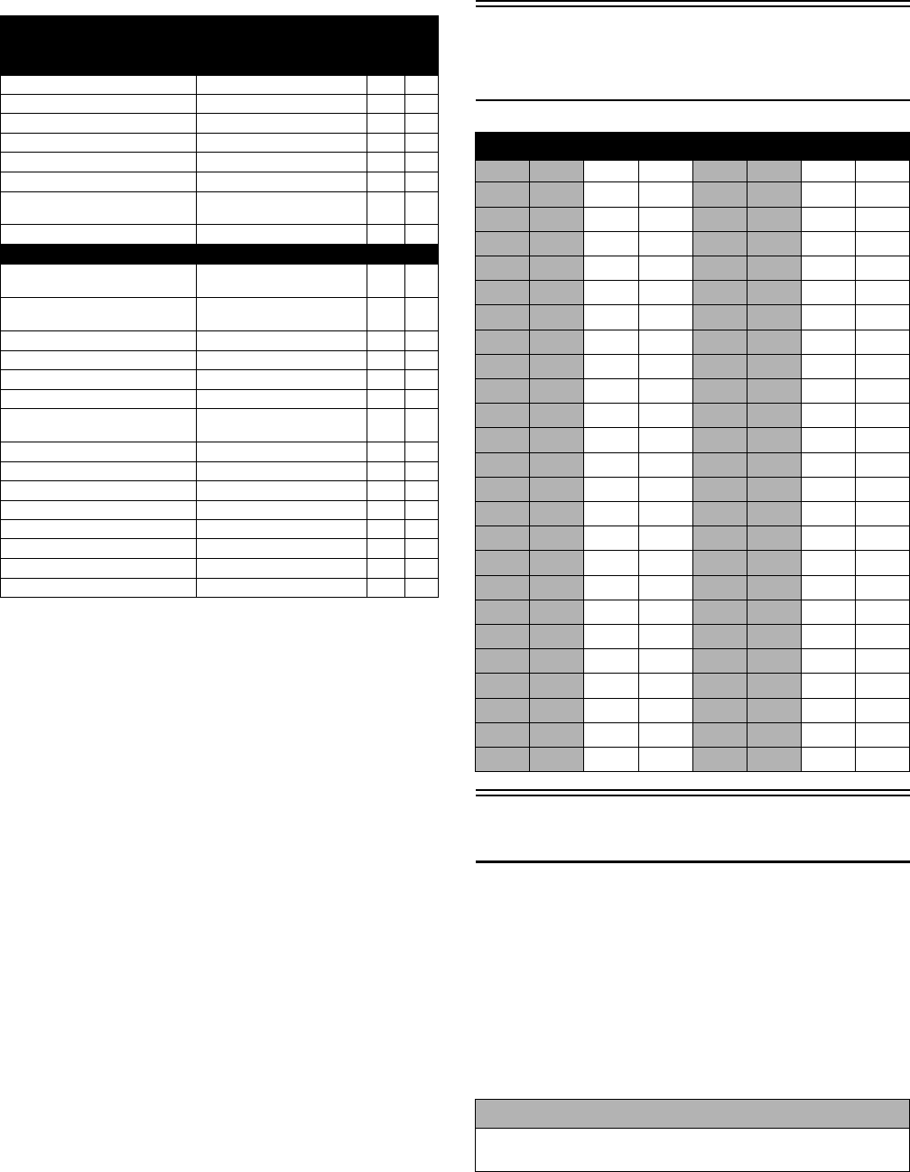
RECOMMENDED
ENGINE/TRANSMISSION OIL
The recommended oil to use is Arctic Cat ACX All
Weather synthetic engine oil, which has been specifi-
cally formulated for use in this Arctic Cat engine.
Although Arctic Cat ACX All Weather synthetic engine
oil is the only oil recommended for use in this engine,
use of any API certified SM 0W-40 oil is acceptable.
OILCHARTJ
RECOMMENDED FRONT
DIFFERENTIAL/REAR DRIVE
LUBRICANT
The recommended lubricant is Arctic Cat Gear Lube or
an equivalent gear lube which is SAE approved 80W-90
hypoid. This lubricant meets all of the lubrication
requirements of the Arctic Cat vehicle front differential
and rear drive.
FILLING GAS TANK
ATV0049B
Since gasoline expands as its temperature rises, the gas
tank must be filled to its specified capacity only. Expan-
sion room must be maintained in the tank particularly if
the tank is filled with cold gasoline and then moved to a
warm area.
Tighten the gas tank cap securely after filling the tank.
Genuine Parts
When replacement of parts is necessary, use only genuine
Arctic Cat parts. They are precision-made to ensure high
quality and correct fit. Refer to the appropriate Illustrated
Parts Manual for the correct part number, quantity, and
description.
Preparation For Storage
1. Clean the seat cushion (cover and base) with a damp
cloth and allow it to dry.
2. Clean the vehicle thoroughly by washing dirt, oil,
grass, and other foreign matter from the entire vehi-
cle. Allow it to dry thoroughly. DO NOT get water
into any part of the engine or air intake.
CAUTION
Any oil used in place of the recommended oil could
cause serious engine damage. Do not use oils which
contain graphite or molybdenum additives. These oils
can adversely affect clutch operation. Also, not recom-
mended are racing, vegetable, non-detergent, and cas-
tor-based oils.
CAUTION
Any lubricant used in place of the recommended lubri-
cant could cause serious front differential/rear drive
damage.
! WARNING
Always fill the gas tank in a well-ventilated area. Never
add fuel to the gas tank near any open flames or with
the engine running. DO NOT SMOKE while filling the
gas tank.
! WARNING
Do not overflow gasoline when filling the gas tank. A
fire hazard could materialize. Always allow the engine to
cool before filling the gas tank.
! WARNING
Do not over-fill the gas tank.
CAUTION
Prior to storing the vehicle, it must be properly serviced
to prevent rusting and component deterioration.

6
3. Either drain the gas tank or add Fuel Stabilizer to the
gas in the gas tank. Remove the air filter housing
cover and air filter. Start the engine and allow it to
idle. Using Arctic Cat Engine Storage Preserver, rap-
idly inject the preserver into the air filter opening for
a period of 10 to 20 seconds; then stop the engine.
Install the air filter and housing cover.
4. Plug the exhaust hole in the exhaust system with a
clean cloth.
5. Apply light oil to the plungers of the shock absorb-
ers.
6. Tighten all nuts, bolts, cap screws, and screws. Make
sure rivets holding components together are tight.
Replace all loose rivets. Care must be taken that all
calibrated nuts, cap screws, and bolts are tightened to
specifications.
7. Fill the cooling system to the bottom of the stand
pipe in the radiator neck with properly mixed cool-
ant.
8. Disconnect the battery cables; then remove the bat-
tery, clean the battery posts and cables, and store in a
clean, dry area.
9. Store the vehicle indoors in a level position.
Preparation After
Storage
Taking the vehicle out of storage and correctly preparing
it will assure many miles and hours of trouble-free riding.
1. Clean the vehicle thoroughly.
2. Clean the engine. Remove the cloth from the exhaust
system.
3. Check all control wires and cables for signs of wear
or fraying. Replace if necessary.
4. Change the engine/transmission oil and filter.
5. Check the coolant level and add properly mixed
coolant as necessary.
6. Charge the battery; then install. Connect the battery
cables.
7. Check the entire brake systems (fluid level, pads,
etc.), all controls, headlights, taillight, brakelight,
and headlight aim; adjust or replace as necessary.
8. Tighten all nuts, bolts, cap screws, and screws mak-
ing sure all calibrated nuts, cap screws, and bolts are
tightened to specifications.
9. Check tire pressure. Inflate to recommended pressure
as necessary.
10. Make sure the steering moves freely and does not
bind.
11. Check the spark plug(s). Clean or replace as neces-
sary.
CAUTION
If the interior of the air filter housing is dirty, clean the
area before starting the engine.
CAUTION
Avoid storing outside in direct sunlight and avoid using
a plastic cover as moisture will collect on the vehicle
causing rusting.
CAUTION
The ignition switch must be in the OFF position prior to
installing the battery or damage may occur to the igni-
tion system.
CAUTION
Connect the positive battery cable first; then the nega-
tive.

7
Periodic Maintenance
This section has been organized into sub-sections which show
common maintenance procedures for the Arctic Cat ROV.
SPECIAL TOOLS
A number of special tools must be available to the techni-
cian when performing service procedures in this section.
Refer to the current Special Tools Catalog for the appro-
priate tool description.
NOTE: Special tools are available from the Arctic
Cat Service Department.
Periodic Maintenance
Chart
A = Adjust I = Inspect C = CleanL = Lubricate R = Replace T = Tighten
* Service/Inspect more frequently when operating in adverse conditions.
** When using an API certified SM 0W-40 oil.
*** When using Arctic Cat ACX All Weather synthetic oil, oil change and strainer inspection interval can be increased to every
1,000 miles or every year.
Description p/n
Compression Tester Kit 0444-213
Hub Retaining Wrench 0444-270
Oil Filter Wrench 0644-389
Spanner Wrench 0444-240
Timing Light 0644-296
Valve Clearance Adjuster 0444-255
Hub Retaining Wrench 0444-270
Spanner Wrench 0444-240
Item
Initial Service
After Break-In
(First Month or
100 Miles)
Every
Day
Every Month
or
Every 100
Miles
Every 3
Months or
Every 300
Miles
Every 6
Months or
Every 500
Miles
Every Year or
Every 1500
Miles
As
Needed
Battery II C
Fuses IR
Air Filter II* R
Valve/Tappet Clearance IIA
Engine Compression I
Spark Plug(s) I I I R (4000 Mi
or 18 Mo)
Muffler/Spark Arrester CR
Gas Hoses II R (2 Yrs)
Throttle Cable Ends/Accelerator Pedal Pivot II C-L A-R
Engine-Transmission Oil Level IA
Engine-Transmission Oil/Filter R R*/R**/R*** R
Front Differential - Rear Drive Lubricant II R (4 Yrs)
Tires/Air Pressure II R
Steering Components II I R
V-Belt IlR
Suspension (Ball joint boots, drive axle boots
front and rear, tie rods, differential and rear
drive bellows)
II R
Nuts/Bolts/Cap Screws TT A
Ignition Timing I
Headlight/Taillight-Brakelight II R
Switches II R
Shift Lever IA-L
Gauges/Indicators II R
Frame/Welds II l
Electrical Connections lC
Complete Brake System
(Hydraulic & Parking)
II
Brake Pads II* R
Brake Fluid IIR (2 Yrs)
Brake Hoses IIR (4 Yrs)
Coolant/Cooling System II R (2 Yrs)
Wheel Lug Nuts TT
8
Lubrication Points
It is advisable to lubricate certain components periodi-
cally to ensure free movement. Apply light oil to the
components using the following list as reference.
A. Accelerator Pedal Pivot/Cable Ends
B. Brake Pedal Pivot
C. Parking Brake Cable Ends
D. Shift Cable
Air Filter
Use the following procedure to remove the filter and
inspect and/or clean it.
CLEANING AND INSPECTING
FILTER
1. Remove the seats; then remove the center console.
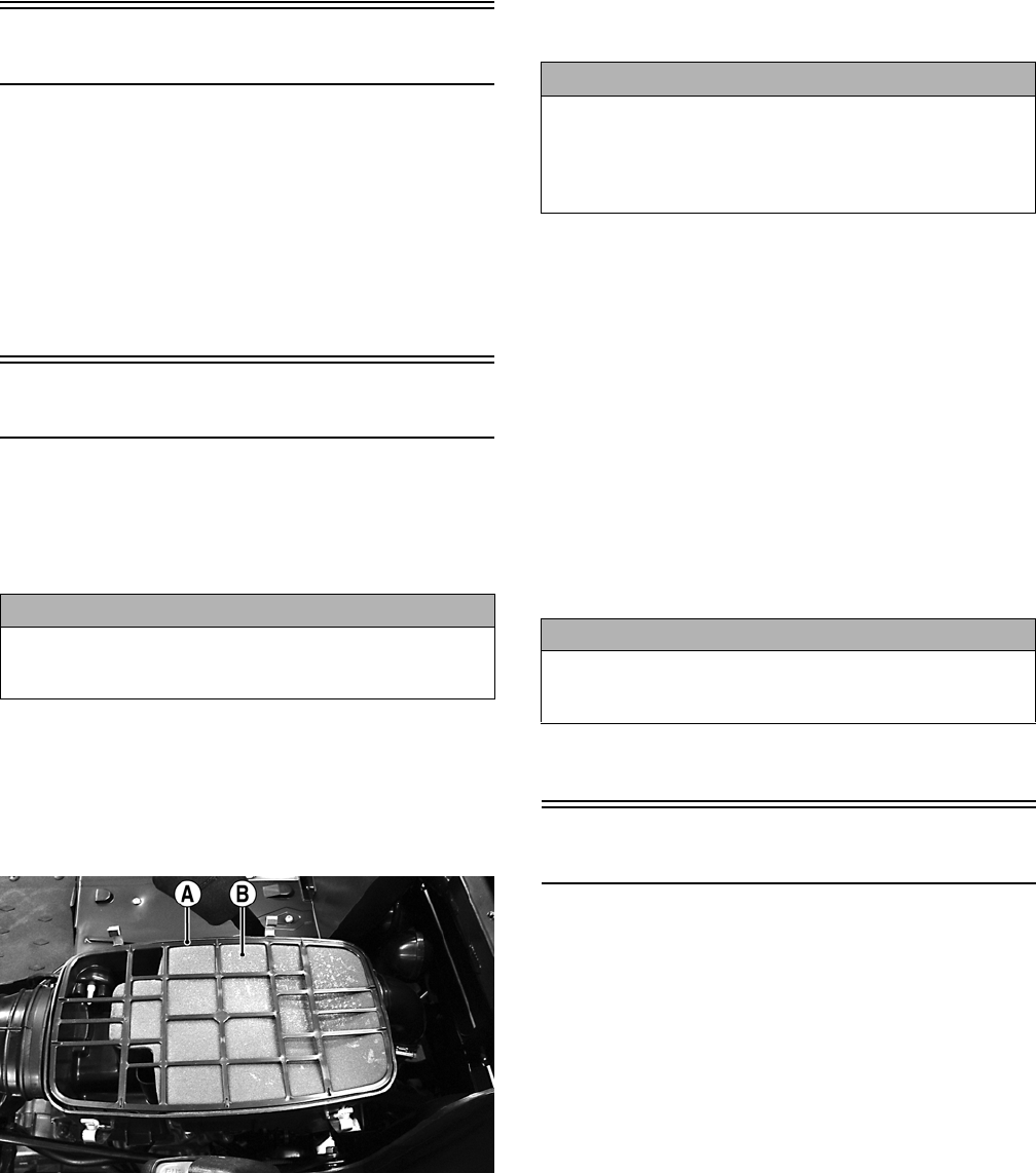
2. Unsnap the four fasteners securing the air cleaner
housing cover and remove the cover.
3. Remove the air filter frame (A); then remove the
foam filter element (B).
PR576A
4. Fill a wash pan larger than the filter with a non-flam-
mable cleaning solvent; then dip the filter in the sol-
vent and wash it.
NOTE: Foam Filter Cleaner and Foam Filter Oil are
available from Arctic Cat.
5. Dry the filter.
6. Put the filter in a plastic bag; then pour in air filter oil
and work the filter. Reattach the filter to the filter screen.
NOTE: Carefully squeeze excessive oil from the fil-
ter element. Do not twist foam to remove oil.
7. Clean any dirt or debris from inside the air cleaner.
Be sure no dirt enters the throttle body.
8. Place the foam filter in the air filter housing; then
position the filter frame on top.
9. Install the air filter housing cover and secure with the
retaining clips; then install the center console and
seats making sure the seats lock securely.
CHECKING AND CLEANING
DRAINS
1. Inspect one-way drains beneath the main housing for
debris and for proper sealing.
2. Replace any one-way drain that is cracked or shows
any signs of hardening or deterioration.
3. Wipe any accumulation of oil or gas from the filter
housing and one-way drains.
Valve/Tappet Clearance
To check and adjust valve/tappet clearance, use the fol-
lowing procedure.
NOTE: The engine must be cold for this procedure.
NOTE: The seats, center console, spark plug, and
air filter housing must be removed for this procedure.
1. Remove the spark plugs and timing inspection plug;
then remove the tappet covers (see the Engine/Trans-
mission section - Servicing Top-Side Components).
NOTE: On the XTZ, remove the crankshaft end cap
and install the special cap screw (left-hand threads)
to rotate the engine.
2. Rotate the crankshaft to the TDC position on the
compression stroke (front cylinder on the XTZ).
CAUTION
Failure to inspect the air filter frequently if the vehicle is
used in dusty, wet, or muddy conditions can damage
the engine.
CAUTION
A torn air filter can cause damage to the vehicle engine.
Dirt and dust may get inside the engine if the element is
torn. Carefully examine the element for tears before and
after cleaning it. Replace the element with a new one if it
is torn.
CAUTION
The one-way drain to the left is the clean air section of
the filter housing. Any leak of this drain will allow dirt
into the engine intake causing severe engine damage.
9
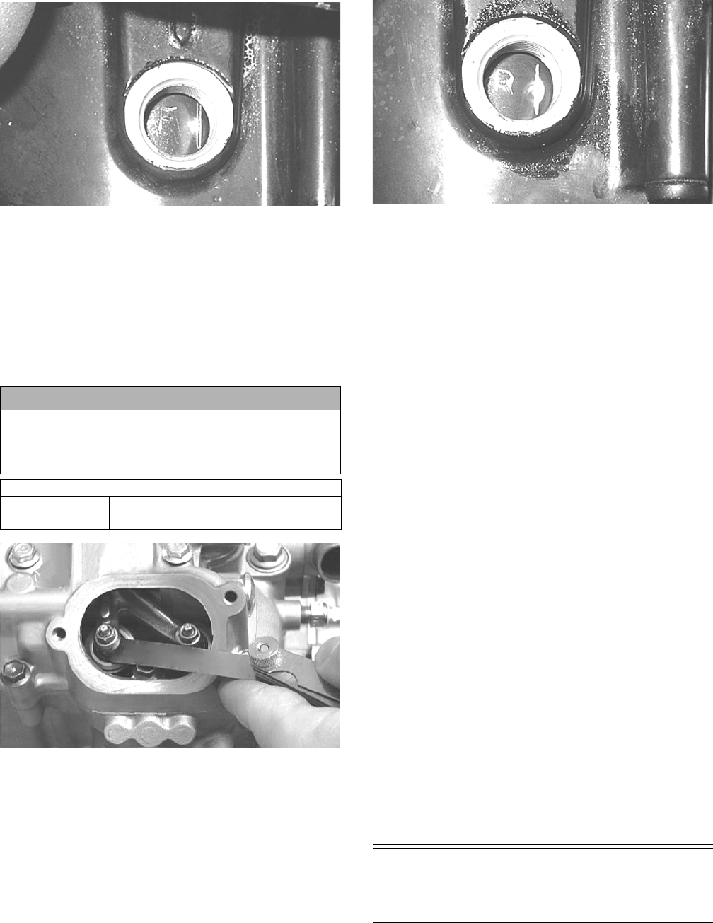
GZ063
NOTE: At this point, the rocker arms and adjuster
screws must not have pressure on them.
Feeler Gauge Procedure
A. Using a feeler gauge, check each valve/tappet clear-
ance. If clearance is not within specifications, loosen
the jam nut and rotate the tappet adjuster screw until
the clearance is within specifications. Tighten each
jam nut securely after completing the adjustment.
CC007DC
B. On the XTZ, rotate the engine 270° to the TDC posi-
tion of the rear cylinder; then repeat step A. The
stamped “R” must be visible.
GZ059
Valve Adjuster Procedure
A. Place the Valve Clearance Adjuster onto the jam
nut securing the tappet adjuster screw; then rotate
the valve adjuster dial clockwise until the end is
seated in the tappet adjuster screw.
B. While holding the valve adjuster dial in place, use
the valve adjuster handle and loosen the jam nut;
then rotate the tappet adjuster screw clockwise
until friction is felt.
C. Align the valve adjuster handle with one of the
marks on the valve adjuster dial.
D. While holding the valve adjuster handle in place,
rotate the valve adjuster dial counterclockwise
until proper valve/tappet clearance is attained.
NOTE: Refer to the appropriate specifications in
Feeler Gauge Procedure sub-section for the proper
valve/tappet clearance.
NOTE: Rotating the valve adjuster dial counter-
clockwise will open the valve/tappet clearance by
0.05 mm (0.002 in.) per mark.
E. While holding the adjuster dial at the proper
clearance setting, tighten the jam nut securely
with the valve adjuster handle.
F. On the XTZ, rotate the engine 270° to the TDC
position of the rear cylinder; then repeat steps
A-E for the rear cylinder.
3. Install the spark plug(s) and timing inspection plug;
then on the XTZ remove the cap screw and install the
crankcase end cap.
4. Place the two tappet covers into position making sure
the proper cap screws are with the proper cover.
Tighten the cap screws securely.
Testing Engine
Compression
To test engine compression, use the following procedure.
CAUTION
The feeler gauge must be positioned at the same angle
as the valve and valve adjuster for an accurate measure-
ment of clearance. Failure to measure the valve clear-
ance accurately could cause valve component damage.
VALVE/TAPPET CLEARANCE
Intake 0.1016 mm (0.004 in.)
Exhaust 0.1524 mm (0.006 in.)
10
NOTE: The engine should be warm (operating tem-
perature) and the battery fully charged for an accurate
compression test. On the XT/XTX, throttle must be in
the wide-open throttle (WOT) position. In the event the
engine cannot be run, cold values are included.
NOTE: The seats and center console must be
removed for this procedure.
1. Remove the high tension lead from the spark plug(s).
2. Using compressed air, blow any debris from around
the spark plug(s).
3. Remove the spark plug(s); then attach the high tension
lead(s) to the plug(s) and ground the plug(s) on the cyl-
inder head(s) well away from the spark plug hole(s).
4. Attach the Compression Tester Kit.
5. While holding the throttle in the full-open position,
crank the engine over with the electric starter until
the gauge stops climbing (five to 10 compression
strokes).
6. If compression is abnormally low, verify the
following items.
A. Starter cranks engine over.
B. Gauge is functioning properly.
C. Throttle in the full-open position.
D. Valve/tappet clearance correct.
E. Engine warmed up.
F. Intake not restricted.
NOTE: To service top-side components, see the
Engine/Transmission section.
7. Pour approximately 30 ml (1 fl oz) of oil into the
spark plug hole(s), reattach the gauge, and retest
compression.
8. If compression increases to normal, service the pis-
ton rings (see the appropriate Engine/Transmission -
Top side Components).
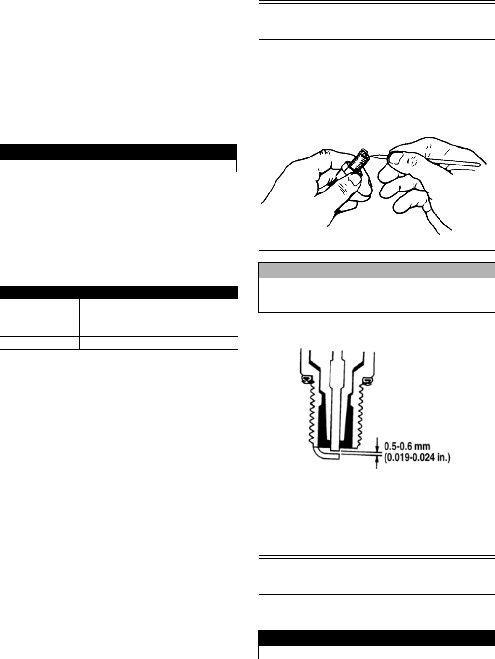
Spark Plug(s)
A light brown insulator indicates that the plug is correct.
A white or dark insulator indicates that the engine may
need to be serviced. To maintain a hot, strong spark, keep
the plug free of carbon.
ATV-0051
Adjust the gap to 0.5-0.6 mm (0.019-0.024 in.).
ATV0052E
When installing a spark plug, be sure to tighten it
securely. A new spark plug should be tightened 1/2 turn
once the washer contacts the cylinder head. A used spark
plug should be tightened 1/8-1/4 turn once the washer
contacts the cylinder head.
Muffler/Spark Arrester
Clean the spark arrester using the following procedure.
1. Remove the cap screws securing the spark arrester
screen assembly to the muffler; then loosen and
remove the spark arrester. Account for a gasket.
! WARNING
Always wear safety glasses when using compressed air.
Model PSI Hot (WOT) PSI Cold (WOT)
XT 120-140 80-120
XTX 125-145 100-140
XTZ (Front) 125-145 80-120
XTZ (Rear) 165-185 150-190
CAUTION
Before removing a spark plug, be sure to clean the area
around the spark plug. Dirt could enter engine when
removing or installing the spark plug.
! WARNING
Wait until the muffler cools to avoid burns.
11
PR837
2. Using a suitable brush, clean the carbon deposits
from the screen taking care not to damage the screen.
NOTE: If the screen or gasket is damaged in any
way, it must be replaced.
3. Install the spark arrester assembly and gasket and
secure with the cap screws. Tighten the cap screws to
48 in.-lb.
Engine/Transmission Oil -
Filter
OIL - FILTER
Change the engine oil and oil filter at the scheduled inter-
vals. The engine should always be warm when the oil is
changed so the oil will drain easily and completely.
NOTE: To change oil and filter, the seats and center
console must be removed.
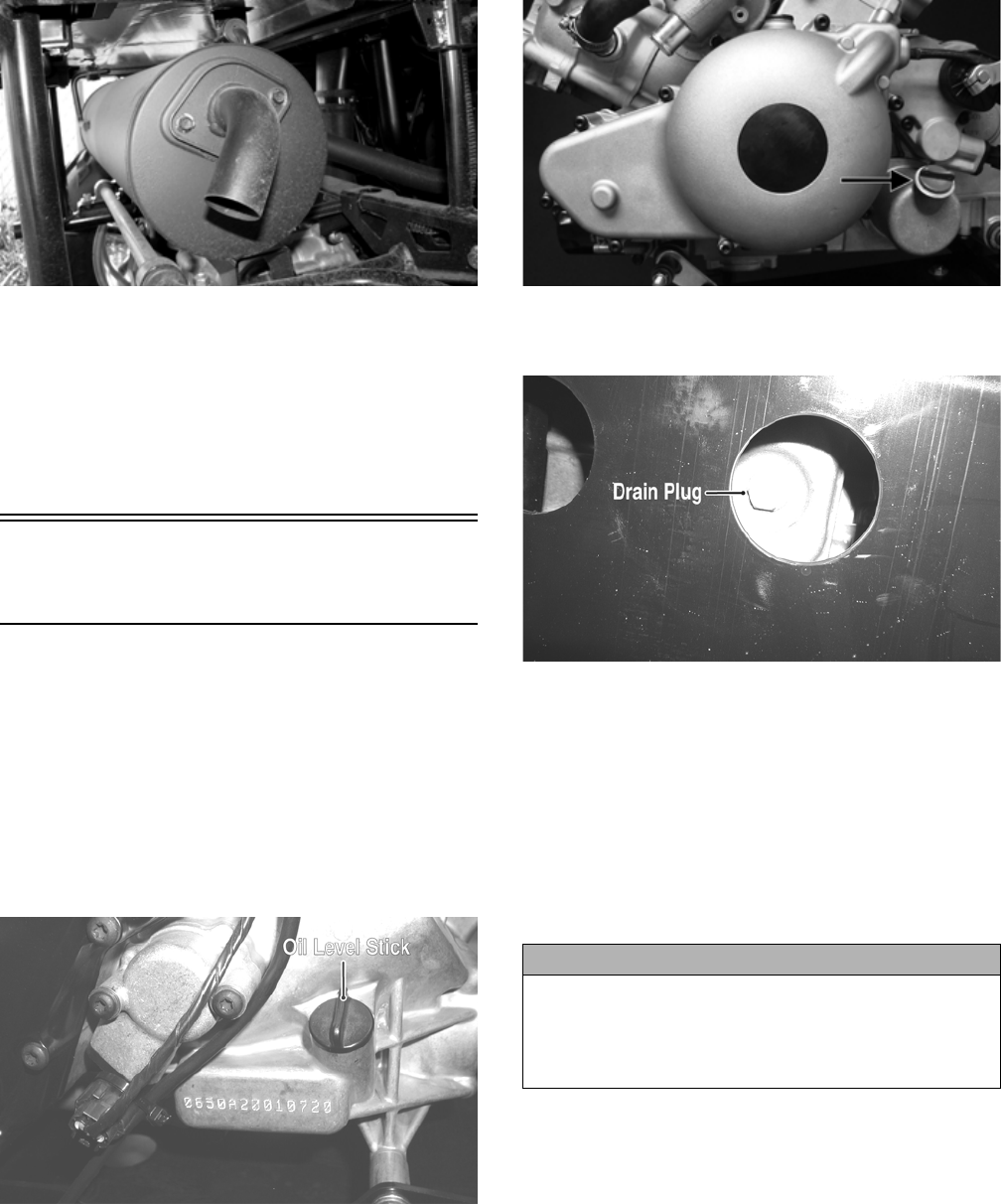
1. Park the vehicle on level ground.
2. Remove the oil level stick/filler plug.
PR053B
GZ415A
3. Remove the drain plug from the bottom of the engine
and drain the oil into a drain pan.
PR078A
4. Using the Oil Filter Wrench and a ratchet handle (or a
socket or box-end wrench), remove the old oil filter.
NOTE: Clean up any excess oil after removing the filter.
5. Apply oil to a new filter O-ring and check to make
sure it is positioned correctly; then install the new oil
filter. Tighten securely.
6. Install the engine drain plug and tighten to 16 ft-lb.
Pour the specified amount of the recommended oil in
the filler hole. Install the oil level stick/filler plug.
7. Start the engine (while the vehicle is outside on level
ground) and allow it to idle for a few minutes.
8. Turn the engine off and wait approximately one minute.
9. Unscrew the oil level stick and wipe it with a clean cloth.
10. Install the oil level stick and thread into the engine case.
NOTE: The oil level stick should be threaded into
the case for checking the oil level.
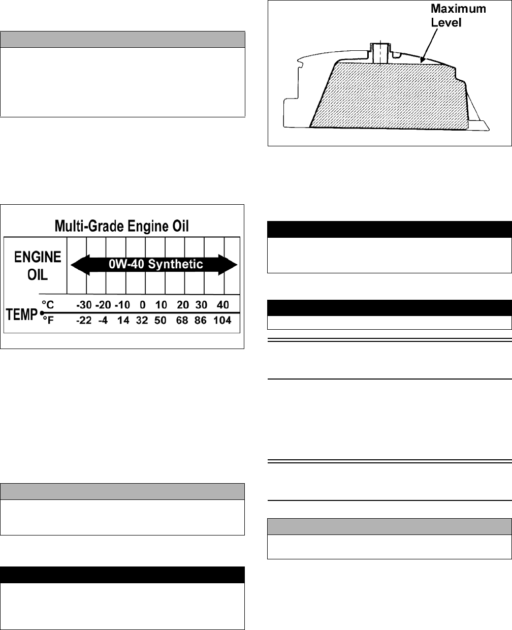
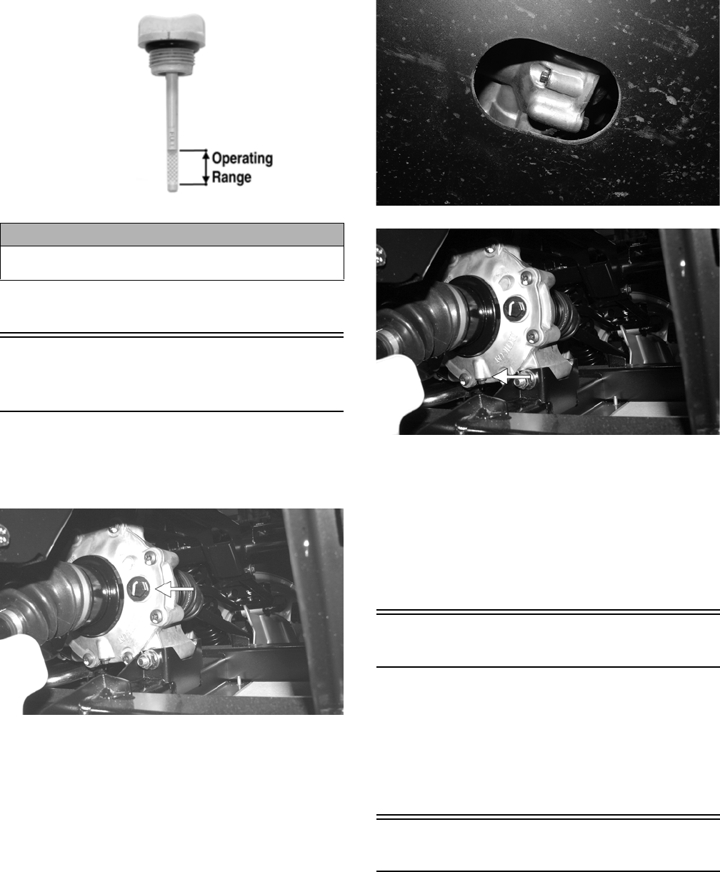
11. Remove the oil level stick; the oil level must be
within the operating range but not exceeding the
upper mark.
CAUTION
Any oil used in place of the recommended oil could cause
serious engine damage. Do not use oils which contain
graphite or molybdenum additives. These oils can
adversely affect clutch operation. Also, not recommended
are racing, vegetable, non-detergent, and castor-based oils.
12
GZ461A
12. Inspect the area around the drain plug and oil filter
for leaks.
Front Differential - Rear
Drive Lubricant
To check lubricant, use the following procedure.
1. Remove the fill plug; the lubricant level should be
one inch below the plug threads.
PR530A
2. If low, add SAE approved 80W-90 hypoid gear lube
as necessary.
To change the lubricant, use the following procedure.
1. Place the vehicle on level ground.
2. Remove each fill plug.
3. Drain the lubricant into a drain pan by removing in
turn the drain plug from each.
HDX255
PR530B
4. After all the lubricant has been drained, install the
drain plugs and tighten to 45 in.-lb.
5. Pour the appropriate amount of recommended lubri-
cant into the fill hole.
6. Install the fill plug.
NOTE: If the lubricant is contaminated with water,
inspect the drain plug, fill plug, and/or bladder.
Driveshaft/Coupling
The following drive system components should be
inspected periodically to ensure proper operation.
A. Spline lateral movement (slop).
B. Coupling cracked, damaged, or worn.
C. Universal joints worn or missing bearings.
Nuts/Bolts/Cap Screws
Tighten all nuts, bolts, and cap screws. Make sure rivets
holding components together are tight. Replace all loose
rivets. Care must be taken that all calibrated nuts, bolts,
and cap screws are tightened to specifications.
CAUTION
Do not over-fill the engine with oil. Always make sure
that the oil level is not above the upper mark.
Rear Drive
13
Headlight/Taillight-Brake-
light
HEADLIGHT
NOTE: The bulb portion of the headlight is fragile.
HANDLE WITH CARE. When replacing the headlight
bulb, do not touch the glass portion of the bulb. If the
glass is touched, it must be cleaned with a dry cloth
before installing. Skin oil residue on the bulb will
shorten the life of the bulb.
To replace the headlight bulb, use the following procedure.
1. Remove the wiring harness connector from the back
of the headlight.
2. Grasp the bulb socket, turn it counterclockwise and
remove, and pull the bulb straight out of the socket.
3. Install the new bulb into the socket and rotate it com-
pletely clockwise in the housing.
4. Install the wiring harness connector.
TAILLIGHT-BRAKELIGHT
To replace the taillight-brakelight bulb, use the following
procedure.
1. Remove the two machine screws and remove the
light assembly.
2. Rotate the bulb socket counterclockwise to remove it
from the light assembly; then pull straight out on the
bulb. Push the new bulb straight into the socket.
3. Install the bulb and socket into the light assembly
and turn clockwise to lock in place.
4. Install the taillight-brakelight assembly on the can-
opy support.
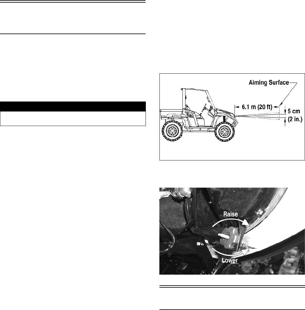
CHECKING/ADJUSTING
HEADLIGHT AIM
The headlights can be adjusted vertically. The geometric center
of the HIGH beam light zone is to be used for vertical aiming.
1. Position the vehicle on a level floor so the headlights
are approximately 6.1 m (20 ft) from an aiming sur-
face (wall or similar aiming surface).
NOTE: There should be an average operating load
on the vehicle when adjusting the headlight aim.
2. Measure the distance from the floor to the mid-point
of each headlight.
3. Using the measurements obtained in step 2, make
horizontal marks on the aiming surface.
4. Make vertical marks which intersect the horizontal
marks on the aiming surface directly in front of the
headlights.
5. Switch on the lights. Make sure the HIGH beam is
on. DO NOT USE LOW BEAM.
6. Observe each headlight beam aim. Proper aim is
when the most intense beam is centered on the verti-
cal mark 5 cm (2 in.) below the horizontal mark on
the aiming surface.
0740-647
7. Using the adjuster knob, adjust each headlight until
correct aim is obtained.
CD714A
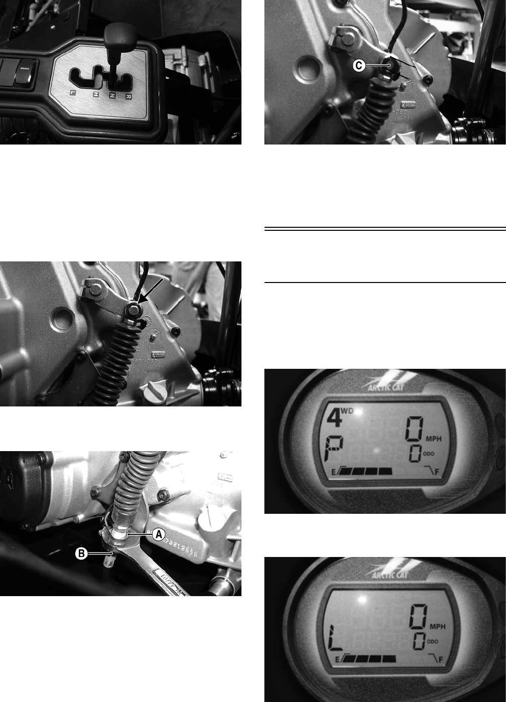
Shift Lever (XT/XTZ)
CHECKING SHIFT CABLE
Set the parking brake and turn the ignition switch on;
then with the shift lever in the neutral position, look for
the (N) indication on the LCD. Shift into high range and
look for the (H) indication, low range for the (L) indica-
tion, and reverse for the (R) indication. Shift the trans-
mission into neutral and turn the ignition switch off.
! WARNING
Do not attempt to remove the bulb when it is hot. Severe
burns may result.
14
PR571
ADJUSTING SHIFT CABLE
To adjust the shift cable, use the following procedure.
1. Set the parking brake; then remove the seats and cen-
ter console.
2. Make sure the shift lever is in neutral; then remove
the E-clip securing the cable end to the shaft arm.
PR567A
3. Loosen nuts (A) and (B) and adjust the cable housing
to align the shift cable end to the shift arm stud (C).
PR568A
PR572A
4. Install the E-clip; then tighten the nuts (A) and (B)
securely.
5. Check each gear shift position for proper gear selec-
tion and make sure the proper icon illuminates on the
LCD; then install the center console and seats.
Shift Lever/Shift Cable
(XTX)
CHECKING
Turn the ignition switch on; then shift the transmission into
park. The letter P should illuminate on the LCD gauge and
the park icon (P) should illuminate. The vehicle should not
be able to move.
HDX203
Move the shift lever all the way to the rear. The letter L
should illuminate on the LCD gauge.
HDX199
15
If either park or low range cannot be reached, the shift
cable must be adjusted.
ADJUSTING
NOTE: Shift cable adjustment should not be neces-
sary unless replacing the shift cable or shift lever.
1. Remove the seats; then remove the battery cover and
center console.
2. Loosen adjuster nut (A) and jam nut (B) and adjust the
cable as necessary to obtain park in the full aft posi-
tion of the shift lever and low range full forward.
Tighten the jam nut securely.
HDX251A
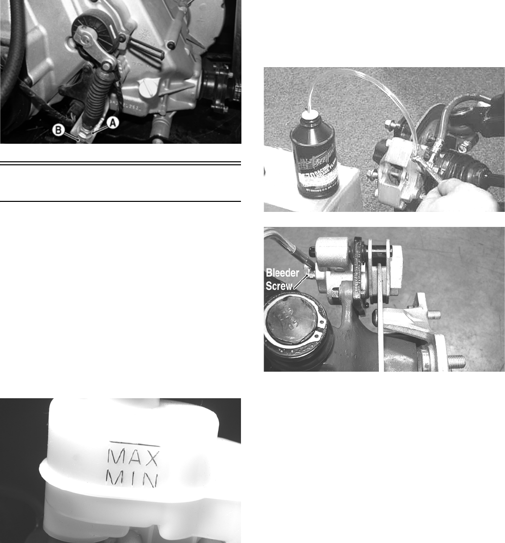
Hydraulic Brake System
NOTE: The XT/XTX models are equipped with drive-
line hydraulic and cable-actuated calipers incorporat-
ing a bleed screw for the hydraulic brake and a cable
adjuster for parking brake adjustment. The XTZ model
is equipped with hydraulic brakes at all four wheels
and a cable only actuated driveline parking brake.
CHECKING/BLEEDING
The hydraulic brake system has been filled and bled at
the factory. To check and/or bleed a hydraulic brake sys-
tem, use the following procedure.
1. With the master cylinder in a level position, check
the fluid level in the reservoir. If the level in the res-
ervoir is not above the MIN, add DOT 4 brake fluid.
PR095
2. Depress the brake pedal several times to check for a
firm brake. If the brake is not firm, the system must
be bled.
3. To bleed the brake system, use the following proce-
dure.
A. Remove the cover and fill the reservoir with DOT
4 Brake Fluid.
B. Install and secure the cover; then slowly depress
the brake pedal several times.
C. Remove the protective cap, install one end of a
clear hose onto the REAR bleeder screw, and
direct the other end into a container; then while
holding slight pressure on the brake pedal, open
the bleeder screw and watch for air bubbles. Close
the bleeder screw before releasing the brake
pedal. Repeat this procedure until no air bubbles
are present.
AF637D
PR377C
NOTE: During the bleeding procedure, watch the
reservoir very closely to make sure there is always a
sufficient amount of brake fluid. When the level falls
below MIN, refill the reservoir before the bleeding
procedure is continued. Failure to maintain a suffi-
cient amount of fluid in the reservoir will result in air
in the system.
D. At this point, perform steps B and C on the
FRONT RIGHT bleeder screw; then move to the
FRONT LEFT bleeder screw(s) and follow the
same procedure.
E. Repeat steps B and C until the brake pedal is firm.
16
4. Carefully check the entire hydraulic brake system
that all hose connections are tight, the bleed screws
are tight, the protective caps are installed, and no
leakage is present.
INSPECTING HOSES
Carefully inspect the hydraulic brake hoses for cracks or
other damage. If found, the brake hoses must be replaced.
CHECKING/REPLACING PADS
The clearance between the brake pads and brake discs is
adjusted automatically as the brake pads wear. The only
maintenance that is required is replacement of the brake
pads when they show excessive wear. Check the thick-
ness of each of the brake pads as follows.
1. Remove a front wheel.
2. Measure the thickness of each brake pad.
PR376A
3. If thickness of either brake pad is less than 1.0 mm
(0.039 in.), the brake pads must be replaced.
NOTE: The brake pads should be replaced as a set.
4. To replace the brake pads, use the following procedure.
A. Remove the wheel.
B. Remove the cap screws securing the caliper
holder to the knuckle; then remove the pads from
the caliper.
PR237
C. Install the new brake pads.
D. Secure the caliper holder to the knuckle with new
“patch-lock” cap screws. Tighten to 20 ft-lb.
PR377B
E. Install the wheel. Tighten in a crisscross pattern in
20 ft-lb increments to 80 ft-lb (aluminum wheels)
or 45 ft-lb (steel wheels).
5. Burnish the brake pads (see Burnishing Brake Pads
in this section).
BRAKE DISC
Using a micrometer, measure the thickness of the brake
disc in the contact surface. If thickness is 0.125-in. or
less, the disc must be replaced. To replace the brake disc,
see the Drive System section – Hub.
Parking Brake (XT/XTZ)
CHECKING
Although the parking brake has been adjusted at the fac-
tory, the brake should be checked for proper operation.
The brake must be maintained to be fully functional.
1. With the engine off, transmission in neutral, and the
parking brake set, attempt to move the vehicle.
2. If the rear wheels are locked, it is adjusted properly.
3. If the rear wheels are not locked, it must be adjusted
(set up).
ADJUSTING
1. Remove the seats and center console.
2. With the parking brake lever released, loosen the
adjuster nut (A); then turn the jam nut (B) clockwise
several turns.
CAUTION
This hydraulic brake system is designed to use DOT 4
brake fluid only. If brake fluid must be added, care must be
taken as brake fluid is very corrosive to painted surfaces.
17
PR682A
3. Turn the adjuster nut clockwise to remove cable slack.
4. Check for proper adjustment by applying the parking
brake and attempting to move the vehicle. The vehi-
cle should not move.
5. If adjustment is correct, tighten the adjuster nut
securely. On the XTZ if further adjustment is required,
repeat steps 2-4. On the XT, proceed to step 6.
6. Release parking brake lever to fully-off position;
then loosen the nut (B) and turn nut (A) clockwise
several turns.
PR097B
7. Check for proper adjustment by applying the parking
brake and attempting to move the vehicle. The vehi-
cle should not move.
8. If adjustment is correct, tighten the nut (B) securely.
NOTE: If the parking brake cannot be “set-up” suffi-
ciently to hold the rear axle, new brake pads must be
installed (proceed to appropriate Replacing Brake
Pads in this sub-section).
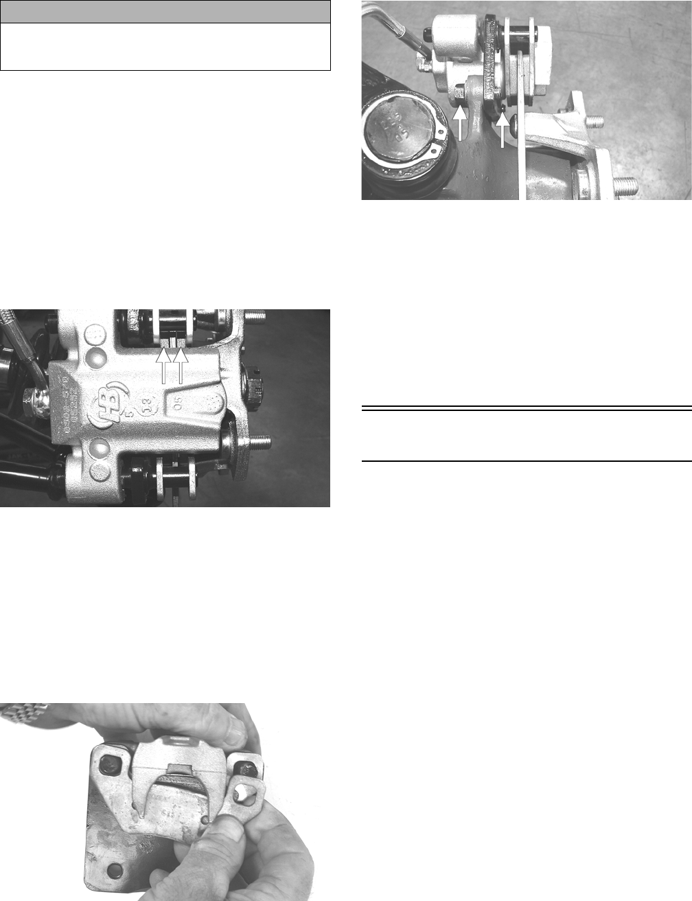
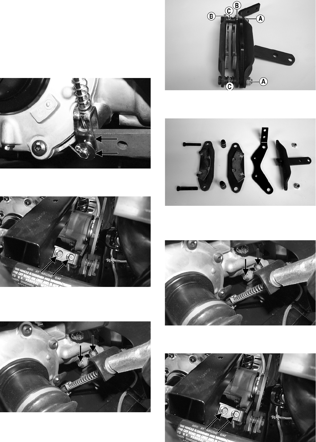
MEASURING/REPLACING BRAKE
PADS (XT)
Removing
1. Remove the parking brake cable.
2. Lift the cargo box; then disconnect the lower lift sup-
port and allow the cargo box to tilt all the way back.
Account for the washer.
UTV355
3. Remove the two cap screws securing the brake cali-
per to the rear drive housing and remove the caliper.
4. Remove the anti-rattle springs; then push in on the
caliper holder and remove the outer brake pad.
Remove the inner pad.
PR466A
Inspecting and Measuring
1. Inspect the pads for gouges, chips, or wear.
2. Inspect the disc for gouges, grooves, cracks, and
warpage.
3. Using a calipers, measure the thickness of each brake
pad.
4. If the thickness of either brake pad is less than 1.0
mm (0.039 in.), the brake pads must be replaced.
NOTE: The brake pads should be replaced as a set.
Installing
1. Place the brake pads into the caliper holder; then
install the anti-rattle springs.
NOTE: The metal backing of the pad will be facing
the actuator when installed properly.
2. Slide brake caliper assembly over the brake disc and
into position on the rear drive housing; then secure
the caliper with new “patch-lock” cap screws tight-
ened to 20 ft-lb.
3. Install and adjust the parking brake cable (see
Adjusting in this sub-section).
4. Connect the lift support to the cargo box.
CAUTION
If after adjusting the parking brake cable the parking brake
will not hold the vehicle, the brake pads must be replaced.
18
NOTE: Whenever installing new pads, the new pads
must be burnished (see Burnishing Brake Pads in
this section).
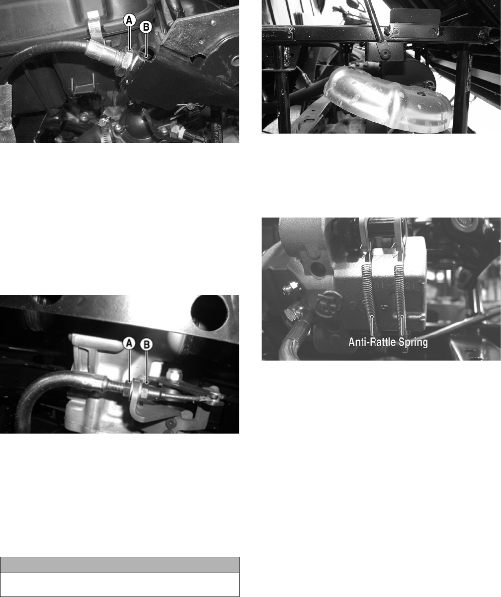
MEASURING/REPLACING BRAKE
PADS (XTZ)
NOTE: The brake pads should be replaced as a set.
1. Disconnect the parking brake cable from the actuator
arm. Account for a flat washer.
PR681A
2. Remove the two cap screws and nuts securing the
cable support to the brake caliper.
PR677A
3. Remove the two cap screws securing the brake cali-
per to the gear case housing; then remove the caliper
assembly from the vehicle.
PR683A
4. Remove the two lock nuts (A) from the brake pad
anchor bolts; then remove the brake pads (B).
Account for two springs and spacers (C).
PR678A
5. Install the new brake pads and anchor bolts with
springs and spacers; then secure with new lock nuts.
PR679
6. Install the brake caliper onto the gear case housing
mounting bracket; then secure with two new
“patch-lock” cap screws and tighten to 20 ft-lb.
PR683A
7. Install the cap screws securing the cable support to
the caliper and tighten securely.
PR677A
19
8. Connect the brake cable to the actuator arm with the
pin and flat washer and secure with the cotter pin;
then adjust the parking brake.
PR681A
NOTE: Whenever installing new pads, the new pads
must be burnished (see Burnishing Brake Pads in
this section).
Burnishing Brake Pads
Brake pads must be burnished to achieve full braking
effectiveness. Braking distance will be extended until
brake pads are properly burnished. To properly burnish
the brake pads, use the following procedure.
1. Choose an area large enough to safely accelerate the
vehicle to 30 mph and to brake to a stop.
2. Accelerate to 30 mph; then depress the brake pedal
to decelerate to 0-5 mph.
3. Repeat procedure 20 times until brake pads are bur-
nished.
4. Adjust the parking brake (if necessary).
5. Verify that the park indicator light illuminates when
the parking brake is set (ignition switch on).
Checking/Replacing
V-Belt
REMOVING
1. Remove the seats and center console; then remove
the left-side seat-base (XT/XTX) or right-side seat
base (XTZ).
2. Remove the floor; then on the XT/XTX, loosen the
gas tank and slide it forward.
3. Remove the cap screws securing the V-belt cover
noting the location of the different-lengthed cap
screws for installing purposes; then using a rubber
mallet, gently tap on the cover tabs to loosen the
cover. Remove the cover.
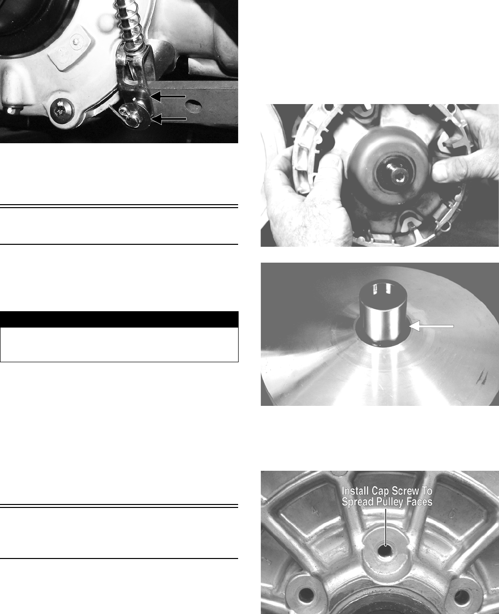
4. Remove the nut securing the movable drive face;
then remove the face. Account for the flat washer
and spacer.
NOTE: Keep the drive face plate in contact with the
drive face when removing or installing the drive face
to prevent the rollers from falling out.
CD963
CD966A
5. Install one of the V-belt cover cap screws into the
driven pulley fixed face; then turn the cap screw
clockwise to spread the pulley faces. Remove the
V-belt.
PR476A
! WARNING
Failure to properly burnish the brake pads could lead to
premature brake pad wear or brake loss. Brake loss can
result in severe injury.
20
GZ085
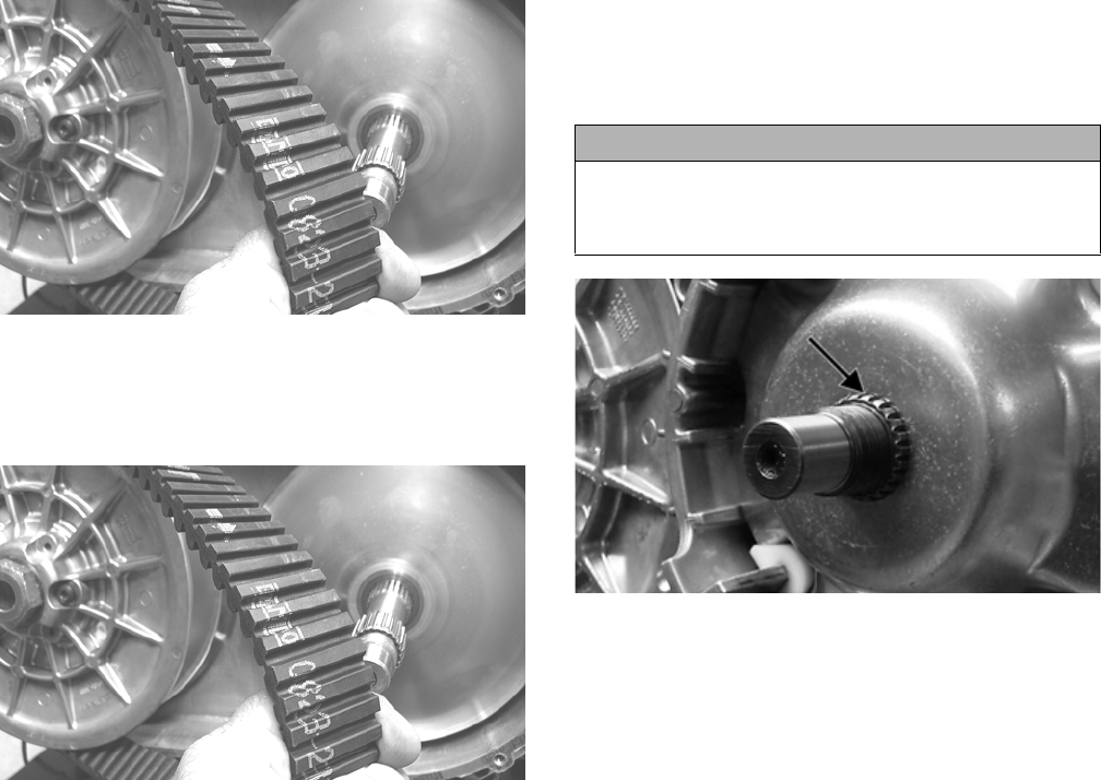
INSTALLING
1. Place the V-belt into position on the driven pulley
and over the front shaft.
GZ085
NOTE: The arrows on the V-belt should point in the
direction of engine rotation.
2. Pinch the V-belt together near its center and slide the
spacer and movable drive face onto the driveshaft.
Secure the drive face with a washer and nut (coated
with red Loctite #271). Using Spanner Wrench,
tighten the nut to 165 ft-lb.
GZ485A
NOTE: At this point, remove the cap screw from the
driven pulley face.
3. With the vehicle in neutral, rotate the V-belt and
driven pulley/clutch counterclockwise until the
V-belt is flush with the top of the driven pulley.
4. Place the V-belt cover gasket into position; then
install the cover and secure with the cap screws mak-
ing sure the different-lengthed cap screws are in their
proper location. Tighten the cap screws to 8 ft-lb.
5. Secure the seat-base with the four cap screws.
Tighten securely.
6. Slide the gas tank into position (XT/XTX) and
secure with the cap screws; then install the floor.
7. Install the seats and center console making sure the
seats lock securely in place.
CAUTION
Make sure the movable drive face plate is fully engaged onto
the splines of the clutch shaft before tightening the nut or
false torque readings may occur. This will cause the assem-
bly to loosen damaging the shaft and clutch face plate.
21
Steering/Frame/Controls
The following steering components should be inspected
periodically to ensure safe and proper operation.
A. Steering wheel secure.
B. Steering has equal and complete full-left and
full-right capability.
C. Steering sector mounting bolts tight.
D. Ball joints not worn, cracked, or damaged.
E. Tie rods not bent or cracked.
F. Knuckles not worn, cracked, or damaged.
G. Cotter pins not damaged or missing.
H. Steering wheel tilt locks securely (XTX).
The frame and welds should be checked periodically for
damage, bends, cracks, deterioration, broken compo-
nents, and missing components.
Steering Assembly (XT)
REMOVING
1. Secure the vehicle on a support stand to elevate the
front wheels; then remove the front wheels.
2. Remove the cotter pins and nuts securing the tie rod
ends to the knuckles; then remove the tie rod ends
from the knuckles.
PR301
3. Make matching alignment marks on the pinion shaft
and lower steering shaft joint.
PR333A
NOTE: Any time steering components are disas-
sembled, all connecting components should be
marked for proper alignment during assembling.
4. Remove the cap screw securing the lower steering
shaft joint to the pinion shaft; then slide the joint free
of the pinion.
PR302
5. Remove two cap screws securing the rack and pinion
assembly to the frame. Account for two nuts and two
washers.
PR303A
6. Remove the rack and pinion assembly from the
right-side.
! WARNING
Make sure the vehicle is solidly supported on the sup-
port stand to avoid injury.
22
PR305
INSPECTING
1. Inspect the tie rod ends for damaged threads, torn
boots, or excessive wear.
2. Inspect the tie rods for bends or deformation.
3. Inspect the rack and pinion-to-tie rod boots for tears
or deterioration.
PR307
4. Check boot clamps for security.
5. Check that the rack and pinion assembly operates
smoothly with no binding from full-left to full-right
position.
6. Inspect for grease seepage from the rack and pinion
assembly.
NOTE: The steering assembly (rack and pinion) is
not repairable and must be replaced as an assembly;
however, the tie rods and boots are replaceable.
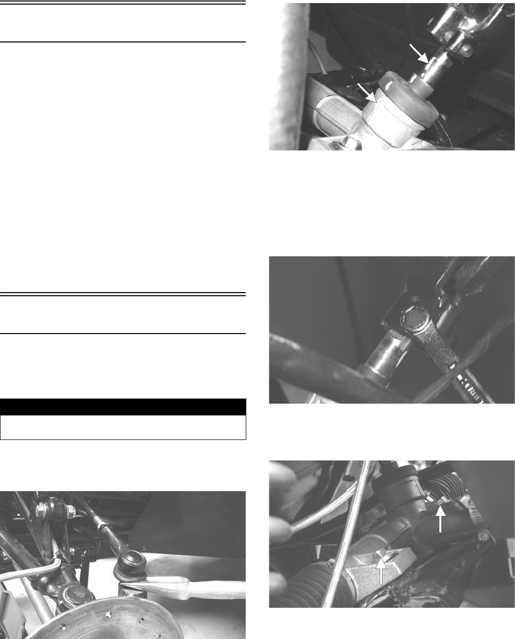
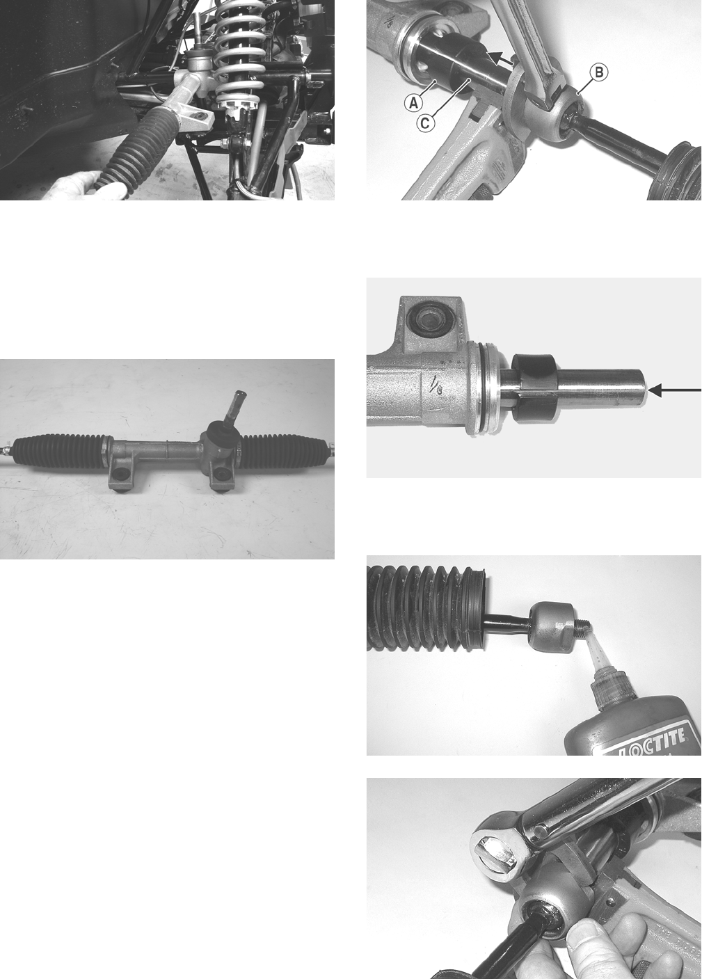
REPLACING TIE RODS/BOOTS
1. Secure the rack and pinion assembly in a vise or
other suitable holding fixture; then remove the tie
rod end, jam nut, and rack boot.
2. Slide the steering stopper (A) away from the inner tie
rod end (B); then hold the rack (C) with a pipe
wrench and remove the inner tie rod end from the
rack.
PR523A
3. Clean all Loctite from the threads in the rack and if
the tie rod is to be reused, clean the tie rod threads
also.
PR526A
4. Coat the thread with red Loctite #271; then install the
tie rod into the rack and using an appropriate
crow-foot, tighten to 52 ft-lb.
PR527
PR519
23
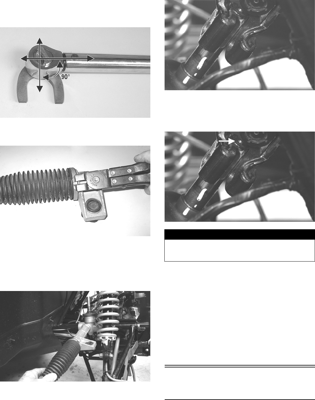
NOTE: Always attach the crow-foot to the torque
wrench with the open end 90° to the torque wrench
handle to ensure accurate torque application.
PR528A
5. Install the rack boot and secure with the clamps; then
loosely install the jam nut and outer tie rod end.
PR520
INSTALLING
1. Place the rack and pinion assembly into position
from the right-side of the vehicle; then secure with
the two cap screws, washers, and nuts. Tighten to 50
ft-lb.
PR305
2. With the rack and the steering wheel centered, slide
the lower steering shaft joint onto the pinion shaft
aligning the match marks.
PR309
3. Apply green Loctite #270 to the cap screw; then
secure the lower steering shaft joint to the pinion
shaft making sure the shaft does not protrude into the
joint beyond the clamping surface.
PR309A
4. Tighten the cap screw to 36 ft-lb; then check that the
steering wheel turns freely.
5. Install the tie rod ends into the steering knuckles;
then secure with the castle nuts (coated with red Loc-
tite #271) tightened to 30 ft-lb.
6. Install the cotter pins and spread to secure.
7. Install the wheels and tighten in a crisscross pattern
in 20 ft-lb increments to 80 ft-lb (aluminum wheels)
or 45 ft-lb (steel wheels). Check the steering system
for full and free travel; then check and adjust the
front wheel alignment (see Checking/Adjusting
Front Wheel Alignment in this section).
Electronic Power
Steering (EPS) (XTX/XTZ)
REMOVING EPS ASSEMBLY
NOTE: Thoroughly troubleshoot the EPS system
prior to replacing the EPS assembly (see the Electri-
cal System section) as there are several possible
external causes for system failure.
! WARNING
Allowing the lower steering shaft joint to extend too far
onto the pinion shaft could cause binding or lock-up of
the steering joint resulting in loss of steering control.
24
1. Support the vehicle on appropriate stands or a lift;
then remove the left front wheel and left front shock
absorber.
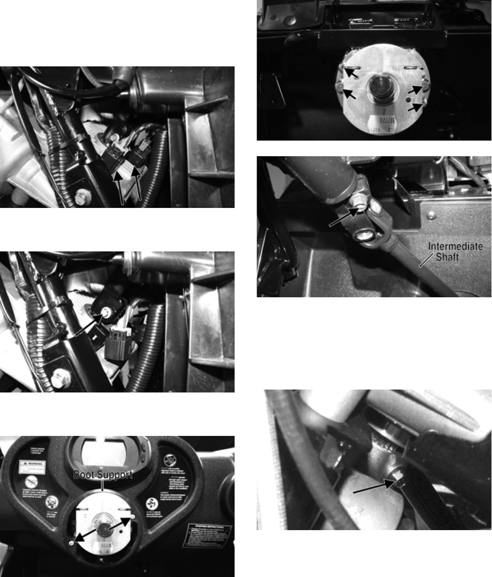
2. Remove the front storage box; then disconnect the
two electrical connectors from the EPS assembly.
PR759A
3. Remove the cap screw securing the intermediate
shaft yoke to the EPS assembly input shaft.
PR760A
4. Remove the steering wheel; then remove the steering
wheel boot support.
PR762A
5. Remove the sheet metal screws securing the dash
assembly to the frame; then disconnect the gauge
plug and the dash harness. Remove the dash assem-
bly.
6. Remove the four cap screws and nuts securing the
steering shaft housing to the steering support; then
remove the cap screw securing the intermediate shaft
yoke to the steering shaft.
PR764A
PR765A
7. Remove the steering shaft housing and shaft from the
steering support and intermediate shaft; then remove
the intermediate shaft from the EPS input shaft.
8. Remove four cap screws securing the EPS assembly
to the frame; then remove the cap screw securing the
rack coupler to the EPS output shaft.
PR761A
NOTE: No repairs are authorized on the EPS assem-
bly and it must be replaced as a complete assembly.
INSTALLING EPS ASSEMBLY
1. Align the slot in the rack coupler to the notch in the
frame (front wheels centered).

25
PR766A
2. Rotate the EPS shaft to align the index (flattened)
spline with the slot in the rack coupler.
PR776A
NOTE: Alignment need only be approximate as final
alignment is not possible until the EPS is engaged
with the coupler.
3. Install the EPS assembly into the coupler turning the
EPS shaft slightly to align the index spline; then seat
the EPS firmly onto the frame.
4. Install four cap screws securing the EPS assembly to
the frame and tighten to 35 ft-lb.
5. Install the cap screw in the EPS to rack coupler and
tighten to 11 ft-lb.
6. Connect the two electrical connectors; then align the
slot in the intermediate steering shaft coupler to the
index (flattened) spline on the EPS input shaft and
install. Install but do not tighten the cap screw.
PR759B
7. Install the steering shaft housing with steering shaft
connecting the steering shaft and intermediate shaft
first; then slide the housing into place on the steering
support.
8. Secure the steering shaft housing to the frame with
four cap screws and nuts. Tighten the 6 mm nuts to 8
ft-lb and the 8 mm nuts to 20 ft-lb.
PR764B
9. Install the cap screw in the intermediate shaft coupler
and tighten to 31 ft-lb; then tighten the cap screw
(from step 6) to 11 ft-lb.
PR765A
10. Install the front storage box; then install the dash and
connect the two electrical connectors. Secure with
sheet metal screws and tighten securely. Do not
over-tighten.
11. Install the steering housing boot; then install the boot
support and secure with two machine screws.
12. Install the steering wheel; then apply a drop of red
Loctite #271 to the threads of the castle nut. Secure
the steering wheel and tighten to 25 ft-lb. Install the
safety pin and cover.
REMOVING TIE RODS
1. Remove the steering rack assembly (see appropriate
Steering Assembly in this section).
2. Support the steering rack assembly in a suitable
holding fixture or bench vise; then cut the securing
band and slide the boot toward the outer tie rod end.
3. Using a punch or chisel, bend the lock washer away
from the flats on the tie rod joint.
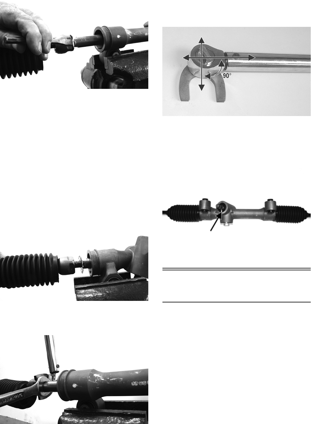
26
PR780
4. Using an appropriate crow-foot and backing wrench,
remove the tie rod assembly.
NOTE: Tie rods come as a complete assembly. No
further disassembly is required.
5. Remove and discard the lock washer.
INSTALLING TIE RODS
1. Remove the tie rod end and lock nut from the tie rod;
then install the tie rod boot onto the tie rod.
2. Install the tie rod lock nut and tie rod end.
3. Coat the tie rod joint threads with red Loctite #271;
then with a new lock washer, thread the tie rod into
the rack.
PR784
4. While holding the rack shaft with a wrench, tighten
the tie rod joint to 37 ft-lb using an appropriate
crow-foot.
PR781
NOTE: Always attach the crow-foot to the torque
wrench with the open end 90° to the torque wrench
handle to ensure accurate torque application.
PR528A
5. Install the boot onto the rack and secure with the
nylon tie.
6. Center the rack in the steering rack assembly and
align the white paint line on the pinion with the mark
on the rack housing.
PR785A
Steering Assembly
(XTX/XTZ)
REMOVING
NOTE: The EPS assembly must be removed prior to
removing the steering assembly (see Electronic
Power Steering (EPS) in this section).
1. Remove the EPS assembly; then remove the right
front wheel.
2. Remove the cotter pins and nuts securing the tie rod
ends to the knuckles; then remove the tie rod ends
from the knuckles.
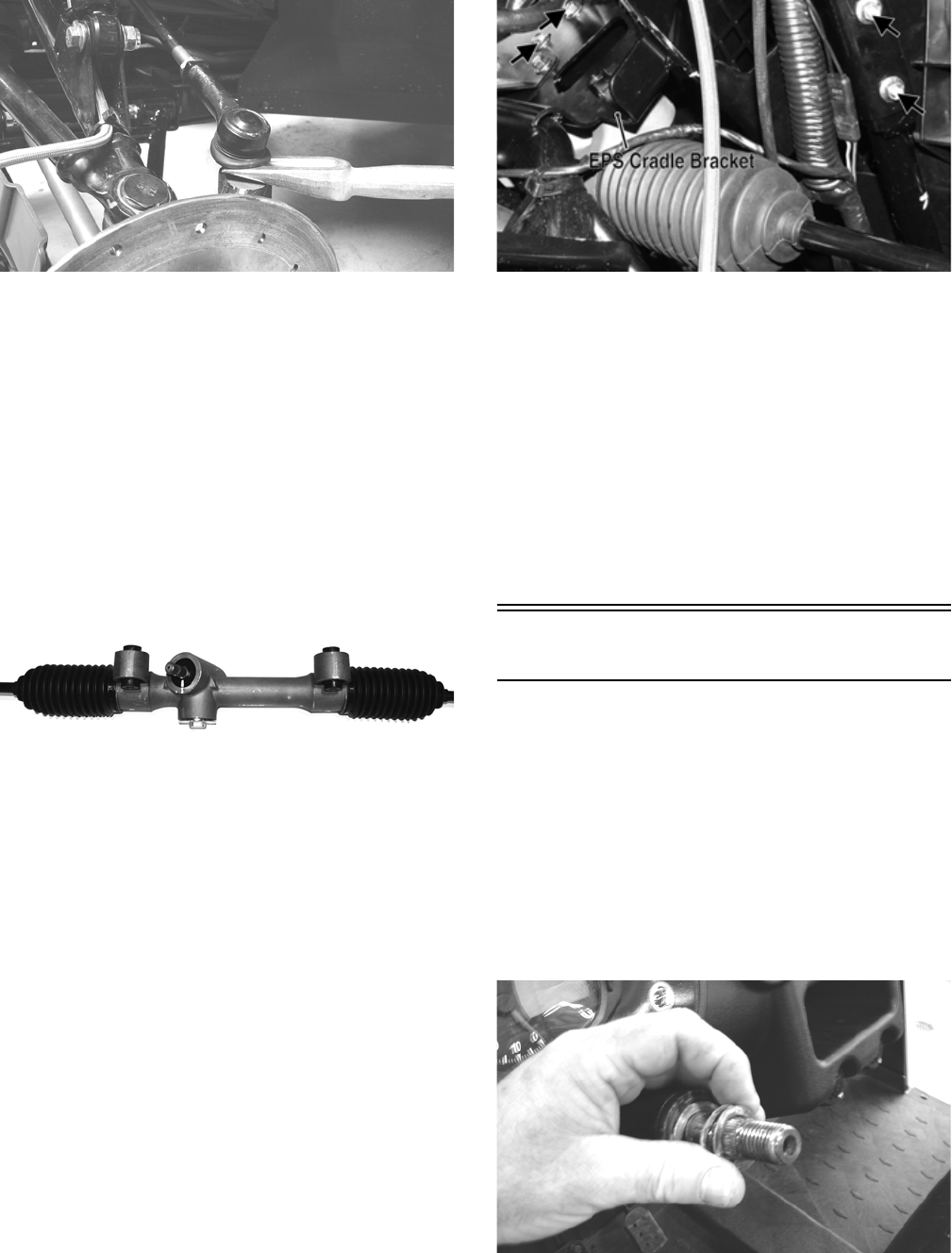
27
PR301
3. Remove the EPS cradle bracket; then remove the cap
screws securing the steering rack assembly to the
rack bracket and remove from the left side.
INSPECTING
1. Inspect the tie rod ends for damaged threads, torn
boots, or excessive wear.
2. Inspect the tie rods for bends or deformation.
3. Inspect the rack and pinion-to-tie rod boots for tears
or deterioration.
PR785
4. Check boot clamps for security.
5. Check that the steering assembly operates smoothly
with no binding from full-left to full-right position.
6. Inspect for grease seepage from the steering assem-
bly.
NOTE: The steering assembly (rack and pinion) is
not repairable and must be replaced as an assembly;
however, the tie rods and boots are replaceable.
INSTALLING
1. From the left side, install the steering assembly to the
frame assembly and secure with two cap screws.
Tighten to 35 ft-lb.
2. Install the EPS cradle bracket and secure with four
cap screws. Do not tighten the cap screws at this
time.
PR773A
3. Place the tie rod ends into the knuckles and secure
with the castle nuts (coated with red Loctite #271).
Tighten to 30 ft-lb; then install new cotter pins.
NOTE: If the slots in the castle nut are not aligned
with the hole in the tie rod end, tighten until the cotter
pin can be installed.
4. Install the EPS assembly (see Installing EPS Assem-
bly sub-section this section); then tighten the cap
screws (from step 2) to 20 ft-lb.
5. Install the wheel and tighten in a crisscross pattern in
20 ft-lb increments to 80 ft-lb (aluminum wheels) or
45 ft-lb (steel wheels).
Steering Wheel
REMOVING
1. Remove the steering wheel cover; then match mark
the steering shaft and steering wheel.
NOTE: Any time steering components are disas-
sembled, all connecting components should be
marked for proper alignment during assembling.
2. Remove the hairpin clip from the steering shaft; then
remove the nut securing the steering wheel and
remove the steering wheel. Account for the flat
thrust washer and two wave washers.
PR226
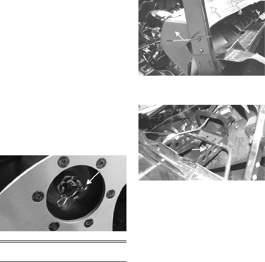
28
INSPECTING
1. Inspect the steering wheel for cracks, missing pad-
ding, or broken spokes.
2. Inspect the splines for wear.
3. Check that the steering wheel is not bent.
INSTALLING
1. Place the flat thrust washer and then the two wave
washers onto the steering shaft.
2. Install the steering wheel aligning the two match
marks; then apply a drop of red Loctite #271 to the
threads of the nut and secure the steering wheel.
Tighten to 25 ft-lb.
NOTE: If a new steering wheel is being installed,
mark the wheel as close as possible to the old wheel
mark; then check for proper positioning with the front
wheels straight forward.
3. Install the hairpin clip on the steering shaft.
NOTE: If the hole in the steering shaft does not
align with the slots in the castle nut, tighten the nut
slightly until the next slot aligns with the hole.
PR684A
Upper Steering Shaft
REMOVING
1. Remove the steering wheel.
2. Remove the screws securing the dash panel to the
frame.
PR181A
3. Slide the dash panel rearward to access the upper
steering shaft joint; then remove the cap screw secur-
ing the upper shaft joint to the steering wheel shaft.
PR313A
4. Match mark the upper steering shaft joint and the
steering wheel shaft; then remove the steering wheel
shaft. Account for the lower thrust washer.
NOTE: Any time steering components are disas-
sembled, all connecting components should be
marked for proper alignment during assembling.
INSPECTING
1. Inspect the steering wheel shaft for excessive wear.
2. Check for worn splines, cracks, or damaged threads.
3. Roll the steering wheel shaft on a flat surface to
check for bends.
4. Inspect the nylon bushings in the steering shaft hous-
ing for cracking or excessive wear.
INSTALLING
1. Slide the steering wheel shaft into the steering hous-
ing; then with the lower thrust washer in position,
align the match marks and slide the upper steering
shaft joint onto the steering wheel shaft.
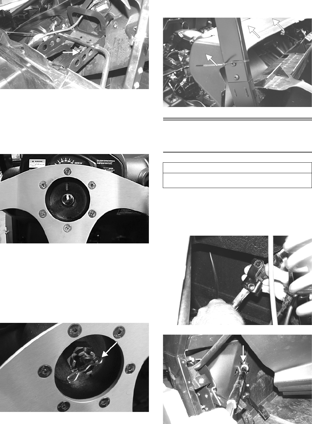
29
PR313A
2. Apply green Loctite #270 to the cap screw; then
install the cap screw in the upper steering shaft joint.
Install the nut and finger-tighten.
3. Align the match marks on the steering wheel shaft
and the steering wheel and slide the steering wheel
onto the splines; then install the nut and fin-
ger-tighten.
PR696
4. Hold rearward pressure on the steering wheel and
tighten the cap screw (from step 2) to 36 ft-lb.
5. Remove the steering wheel nut. Apply one drop of
red Loctite #271 to the threads and install the nut.
Tighten to 25 ft-lb; then install the hairpin clip.
NOTE: If the hole in the steering shaft does not
align with the slots in the castle nut, tighten the nut
slightly until the next slot aligns with the hole.
PR684A
6. Check for freedom of movement of the steering sys-
tem; then install the steering wheel cover.
7. Move the dash panel into position and secure to the
frame and with the existing hardware.
PR181A
Lower Steering Shaft
Assembly
REMOVING
Remove the cap screw securing the lower steering shaft
joint to the pinion shaft; then slide the steering shaft
assembly free and remove through the opening in the
splash panel.
PR304
PR314B
AT THIS POINT
Before beginning this procedure, the upper steering
shaft must be removed.
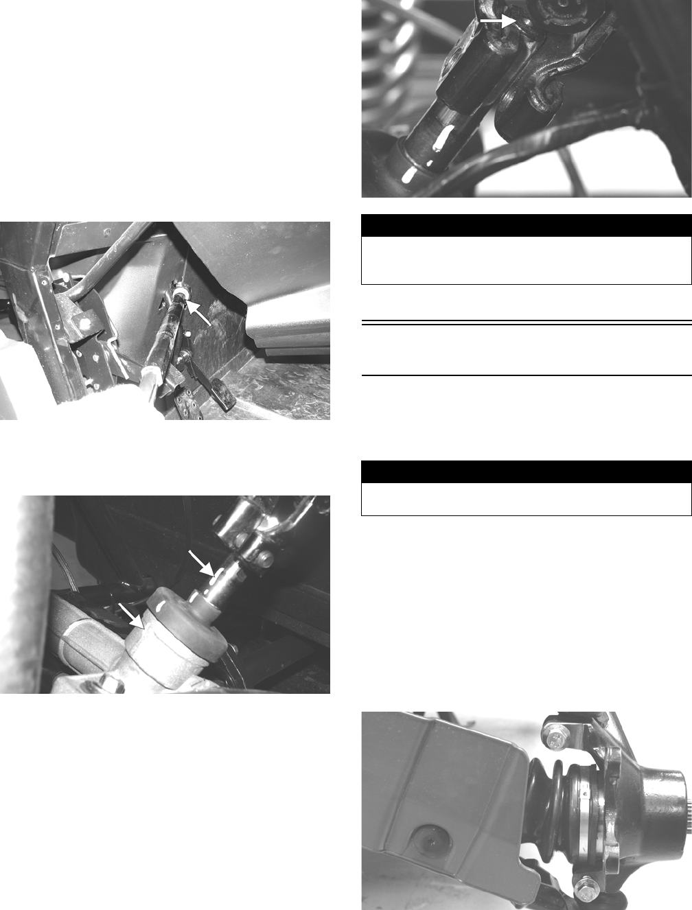
30
INSPECTING
NOTE: The lower steering shaft assembly is not
repairable or rebuildable. If any damage or excessive
wear is detected, the assembly must be replaced.
1. Inspect the joints for excessive wear or looseness.
2. Inspect welds and slip-joints for cracks.
3. Check for excessive wobble in the slip-joint.
INSTALLING
1. Place the steering shaft assembly into position
through the opening in the splash panel.
PR314A
2. Align the match marks on the pinion shaft and the
lower steering shaft joint; then slide the steering
shaft joint onto the pinion shaft.
PR333A
3. Apply green Loctite #270 to the cap screw; then
secure the lower steering shaft joint to the pinion
shaft making sure the pinion shaft does not protrude
into the joint beyond the clamping surface. Tighten
to 36 ft-lb.
PR309A
4. Install the upper steering shaft.
Steering Knuckles
REMOVING AND DISASSEMBLING
1. Secure the vehicle on a support stand to elevate the
wheel; then remove the wheel.
2. Remove the cotter pin from the axle.
3. Remove the nut securing the hub.
4. Remove the brake caliper.
5. Remove the hub assembly.
6. Remove the cotter pin from the tie rod end and
remove the tie rod end from the knuckle.
7. Remove the two cap screws securing the ball joints
in the knuckle.
PR193
8. Tap the ball joint end out of the knuckle; then
remove the knuckle.
! WARNING
Allowing the lower steering shaft joint to extend too far
onto the pinion shaft could cause binding or lock-up of
the steering joint resulting in loss of steering control.
! WARNING
Make sure the vehicle is solidly supported on the sup-
port stand to avoid injury.
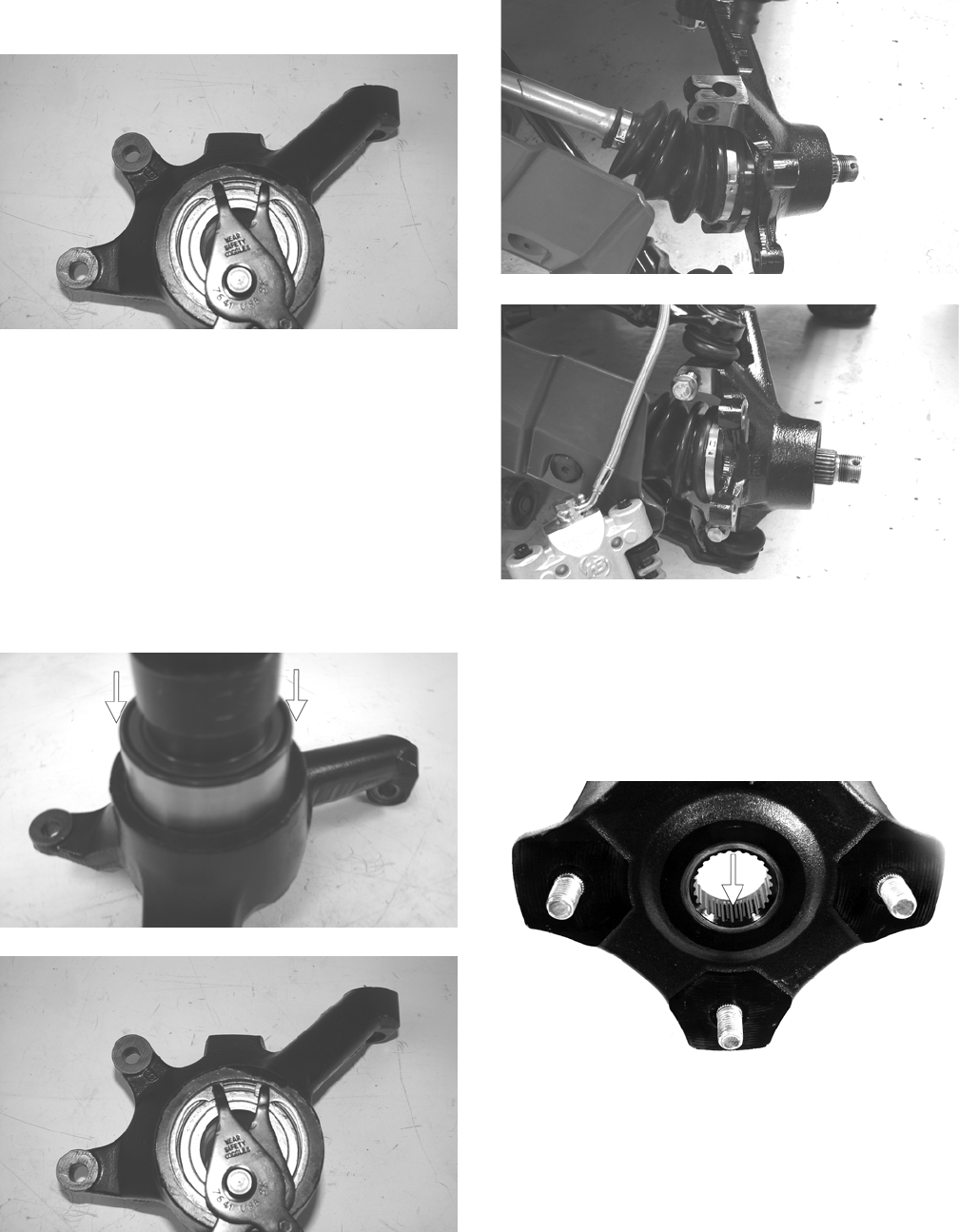
31
9. Remove the snap ring securing the bearing in the
knuckle; then press the bearing out of the knuckle.
PR289
CLEANING AND INSPECTING
1. Clean all knuckle components.
2. Inspect the bearing for pits, scoring, rusting, or pre-
mature wear.
3. Inspect the knuckle for cracks, breaks, or galling of
the bearing surface.
ASSEMBLING AND INSTALLING
1. Using a suitable press and driver, press the bearing
into the knuckle until firmly seated; then install the
snap ring.
PR292A
PR289
2. Install the knuckle to the upper and lower ball joints
and secure with the two cap screws. Tighten to 35
ft-lb.
PR202
PR203
3. Install the tie rod end and secure with the nut (coated
with red Loctite #271). Tighten to 30 ft-lb; then
install a new cotter pin and spread the pin.
NOTE: During assembling, new cotter pins should
be installed.
4. Apply a small amount of grease to the hub splines.
PR290A
5. Install the hub assembly onto the splines of the shaft.
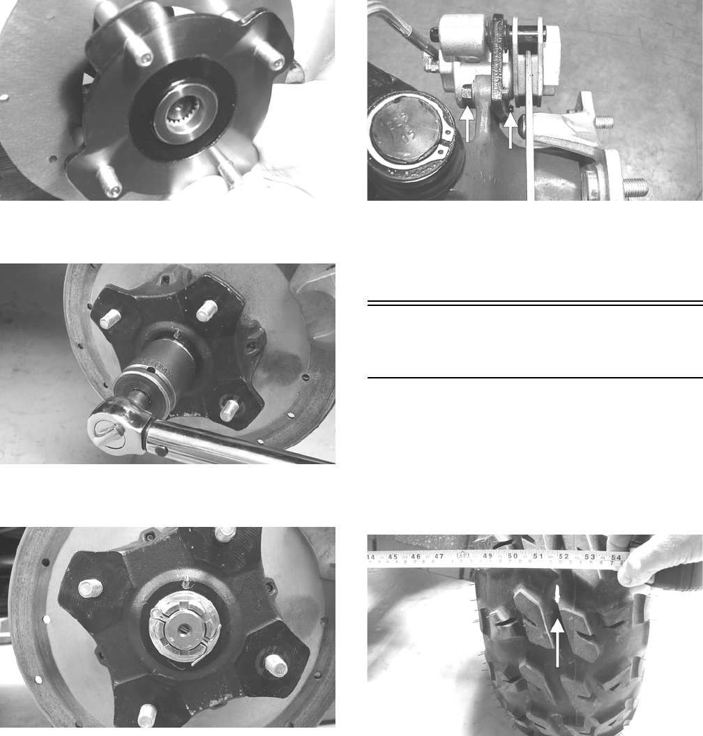
32
CD009
6. Using Hub Retaining Wrench, secure the hub assem-
bly with the nut. Tighten to 200 ft-lb.
PR256
7. Install a new cotter pin and secure by spreading as
shown.
PR260
NOTE: If the hole in the axle shaft does not align
with the slots in the castle nut, tighten the nut until
the hole and slots align.
8. Secure the brake caliper to the knuckle with the two
new “patch-lock” cap screws. Tighten to 20 ft-lb.
PR377B
9. Install the wheel; then tighten in a crisscross pattern
in 20 ft-lb increments to 80 ft-lb (aluminum wheels)
or 45 ft-lb (steel wheels).
10. Remove the vehicle from the support stand.
Checking/Adjusting Front
Wheel Alignment
NOTE: All measurements and adjustments must be
made with the vehicle unloaded.
Mark the center-line of the front tires at the front and rear
of the tire; then using a tape measure, measure and record
the distance between the marks at the front and rear. The
front measurement should be 6-12 mm (1/4-1/2 in.)
greater than the rear measurement (toe-out).
PR087A
To adjust the wheel alignment, use the following proce-
dure.
1. Center the steering wheel; then using an open-end
wrench to hold the tie rod ends, loosen the right-side
and left-side jam nuts.
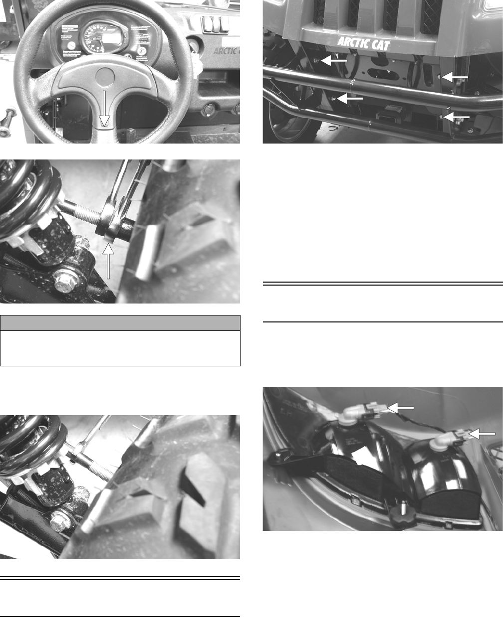
33
PR084A
PR085A
2. Turn the left-side and right-side tie rods in equal
increments to achieve the proper toe-out; then
tighten the jam nuts to 10 ft-lb.
PR086
Front Bumper Assembly
REMOVING
Remove four cap screws and nuts. Account for four lock
washers and eight flat washers.
PR327A
CLEANING AND INSPECTING
1. Clean all bumper components with hot, soapy water.
2. Inspect all welds for cracking or bending.
INSTALLING
Place the bumper assembly into position on the frame;
then secure with the four cap screws and nuts making
sure the flat washers and lock washers are properly posi-
tioned. Tighten to 35 ft-lb.
Hood
REMOVING
1. Open the hood; then disconnect the four headlight
connectors and remove two nylon ties.
PR328A
2. Loosen but do not remove the four cap screws and
flange nuts securing the hood hinge to the frame;
then lower the hood.
CAUTION
Always use a wrench to hold the tie rod ends when loos-
ening or tightening the jam nuts or damage to the boots
could occur.
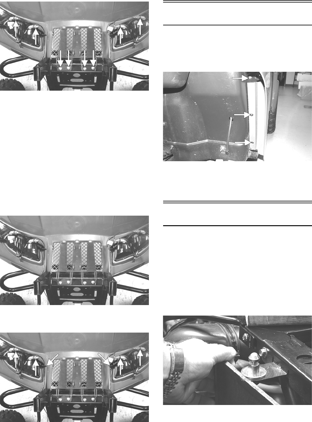
34
PR332A
3. Finish removing the cap screws and flange nuts
(from step 2); then remove the hood assembly.
CLEANING AND INSPECTING
1. Clean all hood components with soap and water.
2. Inspect the hood for cracks and/or loose fasteners.
3. Inspect for any missing decals.
INSTALLING
1. Place the hood into position on the vehicle; then
install the two outside cap screws and flange nuts.
Finger-tighten only at this time.
2. Open the hood; then install the remaining two cap
screws and flange nuts. Tighten all four securely.
PR332
3. Connect the four headlight connectors; then secure
the wires with two new nylon ties.
PR332B
Fenders
REMOVING
Remove three torx-head screws securing each fender to
the frame. Account for a stiffener bracket on the front
fenders.
PR311A
INSTALLING
Place the appropriate fender into position and secure with
existing hardware.
Floor
REMOVING
1. Remove the seats and center console.
2. Remove the cap screws and self-tapping screws
securing the floor to the frame.
3. While pulling forward on the upper-rear of the floor,
lift the rear part of the floor above the seat lock stud.
NOTE: To aid in removing, insert a small wood
block to hold in position.
PR163
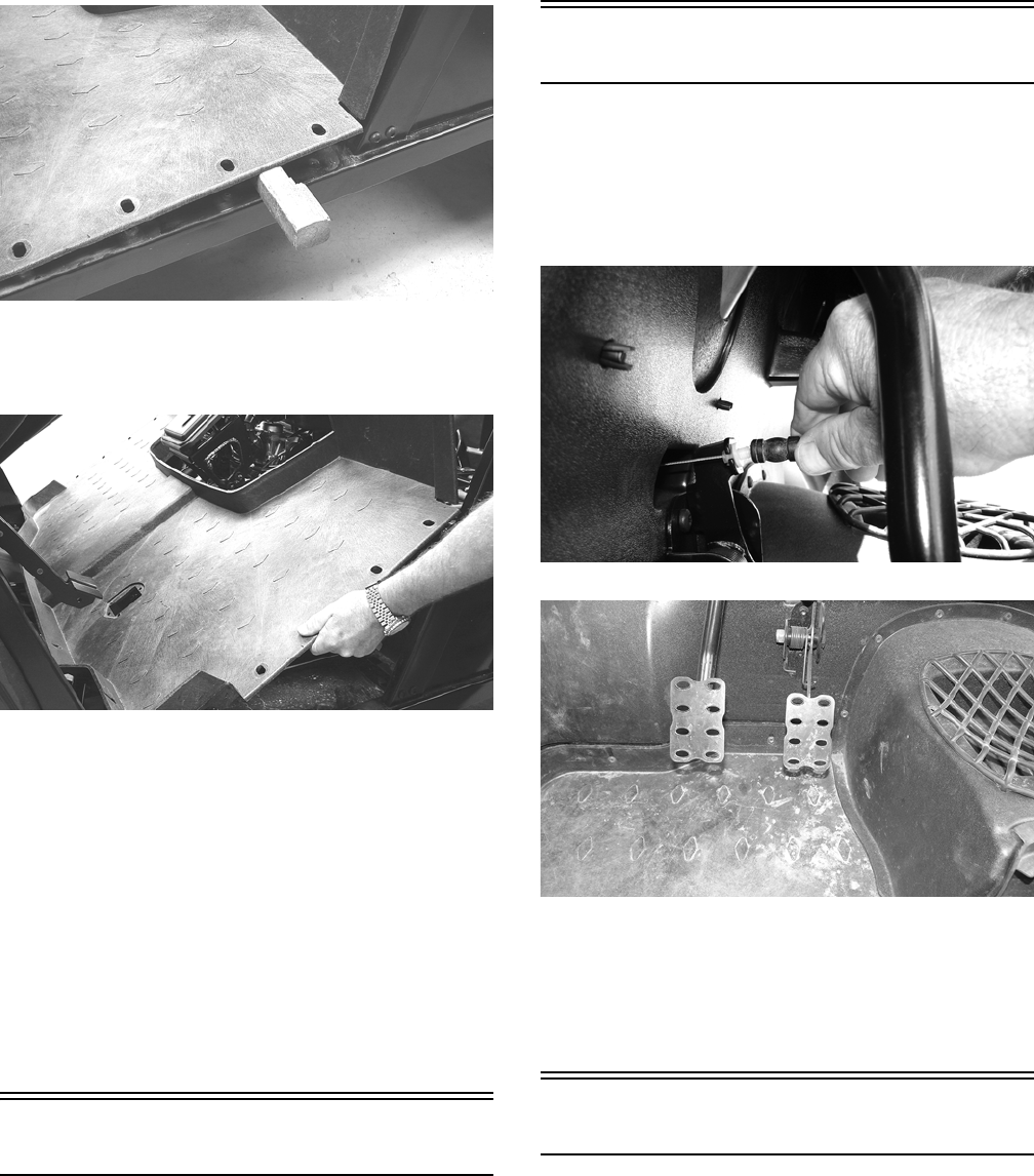
35
PR164
4. From the opposite side of the vehicle repeat step 3;
then lift the rear of the floor up and lift the floor out
of the vehicle.
PR165
CLEANING AND INSPECTING
1. Clean the floor with soap and water.
2. Inspect the floor for cracks or holes.
INSTALLING
1. Place the front of the floor into position in the vehi-
cle first; then lower the rear and push past the seat
lock studs.
2. Secure the floor with the cap screws and self-tap-
pings screws.
3. Install the center console and seats making sure the
seats lock securely into position.
Belly Panel
REMOVING
1. Remove the body screws securing the belly panel to
the underside of the frame.
2. Remove the belly panel.
INSTALLING
1. Place the belly panel into position on the underside
of the frame.
2. Install the body screws. Tighten securely.
Accelerator Pedal
REMOVING
Dislodge the throttle cable holding grommet from the
actuator arm; then remove two torx-head screws and nuts
securing the accelerator pedal assembly to the splash
panel and remove the accelerator pedal.
PR709
UTV354
INSTALLING
Align the mounting holes with the holes in the splash
panel and secure with the two torx-head screws and nuts;
then snap the throttle cable holding grommet into the
actuator arm.
Shift Lever (XT/XTZ)
REMOVING
1. Remove the seats and center console.
2. Remove the flange nut and shoulder screw from the
shift lever pivot; then remove the shift lever.
Account for the shifter spring.
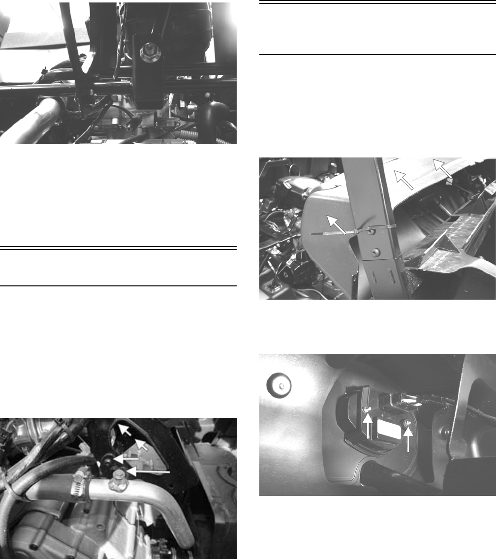
36
PR340
INSTALLING
1. With the shifter spring in place on the shift lever,
install the shift lever onto the shift axle.
2. Install the shoulder screw and secure with the flange
nut (threads coated with blue Loctite #243). Tighten
to 20 ft-lb.
Shift Lever (XTX)
REMOVING
1. Remove the seats and center console; then remove
the shift lever grip.
2. Remove the flange nut securing the shift cable to the
shift arm.
3. Remove the cap screws securing the shift axle to the
frame and remove the shift assembly. Account for
two shift axle retainer plates.
PR819B
INSTALLING
1. Place the shift assembly into position and secure
with two shift axle retainer plates and four cap
screws. Tighten securely.
2. Connect the shift cable to the shift arm and secure
with the flange nut. Tighten securely.
3. Install the jam nut and shift lever grip and tighten
securely; then check for proper shifter operation (see
Periodic Maintenance - Shift Lever/Shift Cable
(XTX)).
LCD Gauge/Indicator
Lights
REPLACING
1. Remove the six screws securing the dash panel to the
frame; then remove the parking brake handle and
jam nut.
2. Slide the dash panel to the rear sufficiently to access
the components.
PR181A
3. Disconnect the multi-pin connector; then remove the
nuts securing the gauge assembly to the dash.
Remove the gauge from the vehicle.
PR284A
4. Place the new gauge into the dash panel opening;
then place the gauge holder over the mounting
screws and secure with the nuts.
5. Plug the multi-pin connector into the gauge; then
turn the ignition switch to the ON position and check
gauge functions.
6. Slide the dash into position and secure with the six
screws.
7. Install the parking brake handle and jam nut.
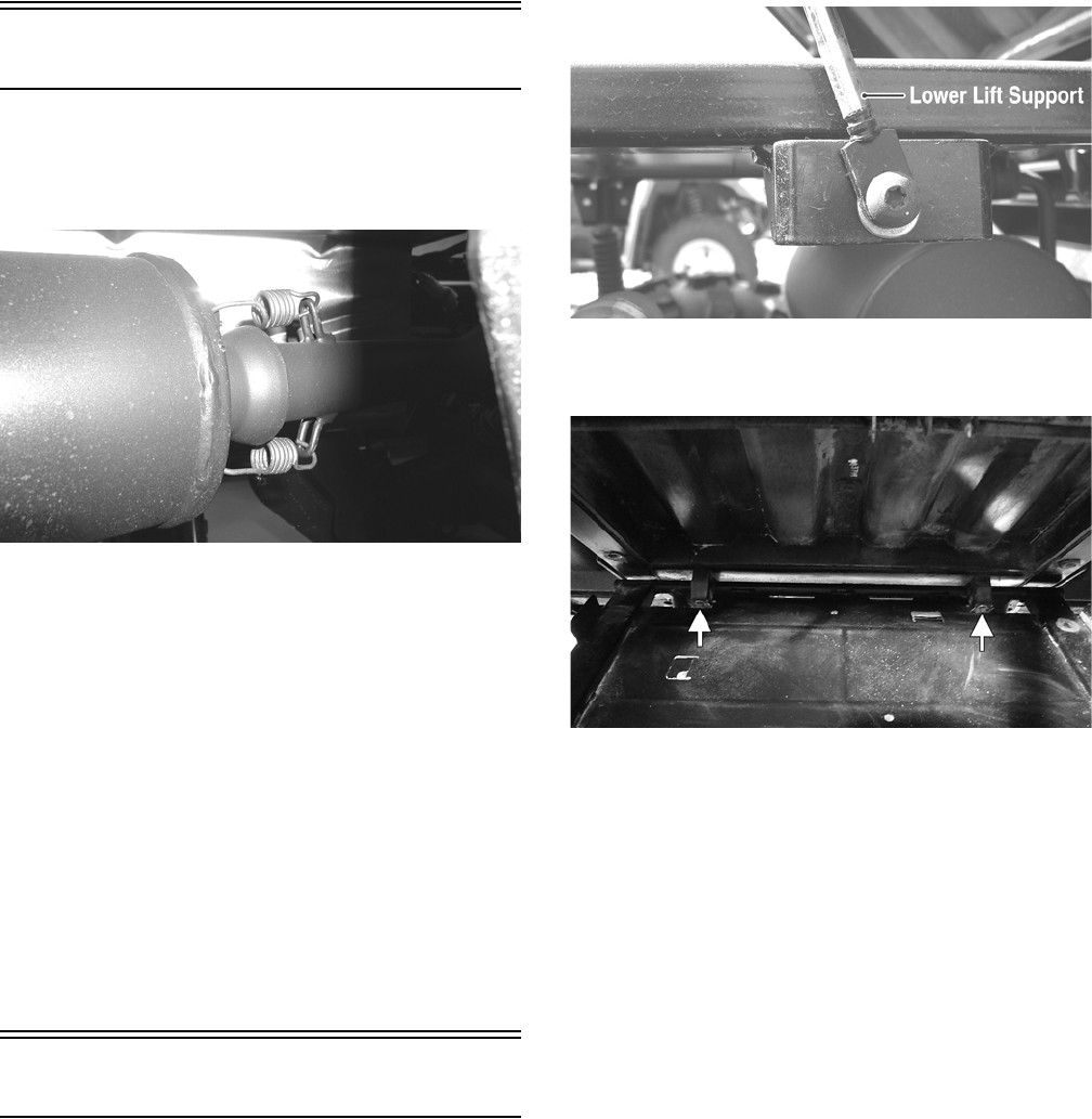
37
Exhaust System
REMOVING MUFFLER
1. Remove the two exhaust springs at the muf-
fler/exhaust pipe juncture.
PR131
2. Slide the muffler assembly clear of the holder pins.
INSPECTING MUFFLER
1. Inspect muffler externally for cracks, holes, and dents.
2. Inspect the muffler internally by shaking the muffler
back and forth and listening for rattles or loose debris
inside the muffler.
NOTE: For additional details on cleaning the muf-
fler/spark arrester, see the Periodic Maintenance sec-
tion.
INSTALLING MUFFLER
1. Place the muffler onto the holder pins and slide into
position.
2. Secure the muffler to the exhaust pipe with the two
exhaust springs.
Cargo Box
REMOVING
1. Raise the cargo box; then remove the cap screw and
nut securing the lower lift support to the frame.
Account for the washer. The cargo box will tilt fully
rearward.
PR473A
2. Loosen but do not remove the four shoulder cap
screws securing the pivot housings to the cargo box.
PR793A
3. Lower the cargo box; then remove the four cap
screws (from step 2).
4. With the help of an assistant or an adequate lift,
remove the cargo box from the vehicle. Account for
four pivot housings.
CLEANING AND INSPECTING
1. Clean all cargo box components with soap and water.
2. Inspect the cargo box for cracks, tears, and loose
hardware.
3. Inspect the welds of the cargo box frame for cracking
or bending.
4. Inspect the cargo box gate latches for smooth operation.
INSTALLING
1. With the help of an assistant or an adequate lift, set
the cargo box into position on the frame; then posi-
tion the two upper pivot housings between the cargo
box and frame. Lightly grease the pivot housings.
2. Align the holes in the upper pivot housings with the
holes in the cargo box; then install the lower pivot
housings and secure with the four shoulder cap
screws. Tighten to 20 ft-lb.
3. Raise the cargo box; then connect the lift support to
the frame, install the cap screw and nut, and tighten
the nut securely.
4. Lower the cargo box and lock into position.

38
Taillight Assembly
REMOVING
1. Remove two torx-head screws securing the taillight
assembly to the rear ROPS tube; then rotate the tail-
light assembly left or right to allow the connector to
clear the access opening.
2. Disconnect the three-prong connector from the bulb
socket and remove the taillight assembly.
INSPECTING
1. Inspect wiring harness, three-prong connector, lens,
base, cap screws, and socket for damage.
2. Inspect all wires for corroding, pinching, and cracking.
3. Inspect the bulb for wattage, voltage, and proper
operation.
INSTALLING
1. Connect the three-prong connector to the bulb
socket; then place the taillight assembly into position
on the rear ROPS tube.
2. Install the two torx-head screws and tighten securely.
Seats
REMOVING/INSTALLING
1. To remove a seat, pull the seat lock lever up. Raise
the front of the seat and slide it forward.
2. To install a seat, slide the rear of the seat into the seat
retainers and push down firmly on the front of seat.
The seat should automatically lock into position.
Troubleshooting
Problem: Handling too heavy or stiff
Condition Remedy
1. Front wheel alignment incorrect
2. Lubrication inadequate
3. Tire inflation pressure incorrect
4. Tie rod ends seizing
5. Linkage connections seizing
1. Adjust alignment
2. Lubricate appropriate components
3. Adjust pressure
4. Replace tie rod ends
5. Repair - replace connections
Problem: Steering oscillation
Condition Remedy
1. Tires inflated unequally
2. Wheel(s) wobbly
3. Wheel hub cap screw(s) loose - missing
4. Wheel hub bearing worn - damaged
5. Tie rod ends worn - loose
6. Tires defective - incorrect
7. A-arm bushings damaged
8. Bolts - nuts (frame) loose
1. Adjust pressure
2. Replace wheel(s)
3. Tighten - replace cap screws
4. Replace bearing
5. Replace - tighten tie rod ends
6. Replace tires
7. Replace bushings
8. Tighten bolts - nuts
Problem: Steering pulling to one side
Condition Remedy
1. Tires inflated unequally
2. Front wheel alignment incorrect
3. Wheel hub bearings worn - broken
4. Frame distorted
5. Shock absorber defective
1. Adjust pressure
2. Adjust alignment
3. Replace bearings
4. Repair - replace frame
5. Replace shock absorber
Problem: Steering impaired
Condition Remedy
1. Tire pressure too high
2. Steering linkage connections worn
3. Cap screws (suspension system) loose
1. Adjust pressure
2. Replace connections
3. Tighten cap screws
Problem: Tire wear rapid or uneven
Condition Remedy
1. Wheel hub bearings worn - loose
2. Front wheel alignment incorrect
1. Replace bearings
2. Adjust alignment

39
Problem: Steering noise
Condition Remedy
1. Caps screws - nuts loose
2. Wheel hub bearings broken - damaged
3. Lubrication inadequate
1. Tighten cap screws - nuts
2. Replace bearings
3. Lubricate appropriate components
Problem: Rear wheel oscillation
Condition Remedy
1. Rear wheel hub bearings worn - loose
2. Tires defective - incorrect
3. Wheel rim distorted
4. Wheel hub cap screws loose
5. Parking brake adjusted incorrectly
6. Rear suspension arm-related bushing worn
7. Rear shock absorber damaged
8. Rear suspension arm nut loose
1. Replace bearings
2. Replace tires
3. Replace rim
4. Tighten cap screws
5. Adjust parking brake
6. Replace bushing
7. Replace shock absorber
8. Tighten nut

40
Engine/Transmission
This section has been organized into sub-sections which
show a progression for the complete servicing of the Arc-
tic Cat ROV engine/transmission.
To service the center crankcase halves, the engine/trans-
mission must be removed from the frame. To service
top-side, left-side, and right-side components, the
engine/transmission does not have to be removed from
the frame.
NOTE: Arctic Cat recommends the use of new gas-
kets, lock nuts, and seals and lubricating all internal
components when servicing the engine/transmis-
sion.
NOTE: A new ATV and an overhauled ATV engine
require a “break-in” period. The first 10 hours (or 200
miles) are most critical to the life of this ATV. Proper
operation during this break-in period will help assure
maximum life and performance from the ATV. Instruct
the customer to follow the proper break-in procedure
as described in the Operators Manual.
SPECIAL TOOLS
A number of special tools must be available to the techni-
cian when performing service procedures in this section.
Refer to the current Special Tools Catalog for the appro-
priate tool description.
NOTE: Special tools are available from the Arctic
Cat Service Department.
Description p/n
Seal Protector Tool 0444-252
Crankcase Separator/Crankshaft Remover 0444-152
Magneto Rotor Remover Set 0444-254
Piston Pin Puller 0644-328
Secondary Drive Gear Holder 0444-253
Spanner Wrench 0544-005
Surface Plate 0644-016
V Blocks 0644-535

41
Troubleshooting
Problem: Engine will not start or is hard to start (Compression too low)
Condition Remedy
1.
Valve clearance
out of adjustment
2.
Valve guides
worn
3.
Valves
mistimed
4.
Piston rings
worn - broken
5.
Cylinder bore
worn
6.
Starter motor
cranks too slowly - does not turn
1. Adjust clearance
2. Repair - replace guides
3. Retime engine
4. Replace rings
5. Replace cylinder
6. See the Electrical System section
Problem: Engine will not start or is hard to start (No spark)
Condition Remedy
1.
Spark plug(s)
fouled
2.
Spark plug(s)
wet
3.
Magneto
defective
4.
ECM
defective
5.
Ignition coil
defective
6.
High-tension lead
open - shorted
1. Clean - replace plug(s)
2. Clean - dry plug(s)
3. Replace stator coil
4. Replace ECM
5. Replace ignition coil
6. Replace high tension lead
Problem: Engine will not start or is hard to start (No fuel reaching the fuel injector)
Condition Remedy
1.
Gas tank vent hose
obstructed
2.
Fuel hose
obstructed
3.
Fuel screens
obstructed
4.
Fuel pump
defective
1. Clean vent hose
2. Clean - replace hose
3. Clean - replace inlet screen - valve screen
4. Replace fuel pump
Problem: Engine stalls easily
Condition Remedy
1.
Spark plug(s)
fouled
2.
Magneto
defective
3.
ECM
defective
4.
Fuel injector
obstructed
5.
Valve clearance
out of adjustment
1. Clean - replace plug(s)
2. Replace stator coil
3. Replace ECM
4. Replace fuel injector
5. Adjust clearance
Problem: Engine noisy (Excessive valve chatter)
Condition Remedy
1.
Valve clearance
excessive
2.
Valve spring(s)
weak - broken
3.
Rocker arm
-
rocker arm shaft
worn
4.
Camshaft
worn
1. Adjust clearance
2. Replace spring(s)
3. Replace arm - shaft
4. Replace camshaft
Problem: Engine noisy (Noise seems to come from piston)
Condition Remedy
1.
Piston - cylinder
worn
2.
Combustion chamber carbon
buildup
3.
Piston pin - piston pin bore
worn
4.
Piston rings - ring groove(s)
worn
1. Replace - service piston - cylinder
2. Clean cylinder head and piston
3. Replace - service pin - bore
4. Replace rings - piston
Problem: Engine noisy (Noise seems to come from timing chain)
Condition Remedy
1.
Chain
stretched
2.
Sprockets
worn
3.
Tension adjuster
malfunctioning
1. Replace chain
2. Replace sprockets
3. Repair - replace adjuster
Problem: Engine noisy (Noise seems to come from crankshaft)
Condition Remedy
1.
Main bearing
worn - burned
2.
Lower rod-end bearing
worn - burned
3.
Connecting rod side clearance
too large
4.
Centrifugal clutch
loose
5.
Rotor/flywheel
loose
1. Replace bearing
2. Replace crankshaft assembly
3. Replace crankshaft assembly
4. Tighten - replace clutch
5. Tighten - replace flywheel - crankshaft
Problem: Engine noisy (Noise seems to come from transmission)
Condition Remedy
1.
Gears
worn - chipped
2.
Splines
worn
3.
Primary gears
worn - chipped
4.
Bearings
worn
5.
Bushing
worn
1. Replace gears
2. Replace shaft(s)
3. Replace gears
4. Replace bearings
5. Replace bushing

42
Problem: Engine noisy (Noise seems to come from secondary bevel gear and final driven shaft)
Condition Remedy
1.
Drive - driven bevel gears
damaged - worn
2.
Backlash
excessive
3.
Tooth contact
improper
4.
Bearing
damaged
5.
Gears
worn - chipped
6.
Splines
worn
1. Replace gears
2. Adjust backlash
3. Adjust contact
4. Replace bearing
5. Replace gears
6. Replace shaft(s)
Problem: Engine idles poorly
Condition Remedy
1.
Valve clearance
incorrect
2.
Valve seating
poor
3.
Valve guides
defective
4.
Rocker arms - arm shaft
worn
5.
Magneto
defective
6.
ECM
defective
7.
Spark plug(s)
fouled -
gap
too wide
8.
Ignition coil
defective
9.
Fuel injector
obstructed
1. Adjust clearance
2. Replace valves/cylinder head
3. Replace guides
4. Replace arms - shafts
5. Replace stator coil
6. Replace ECM
7. Adjust gap - replace plug(s)
8. Replace ignition coil
9. Replace fuel injector
Problem: Engine runs poorly at high speed
Condition Remedy
1.
High RPM “cut out”
against RPM limiter
2.
Valve springs
weak
3.
Valve timing
incorrect
4.
Cams - rocker arms
worn
5.
Spark plug gap
too narrow
6.
Ignition coil
defective
7.
Air cleaner element
obstructed
8.
Fuel hose
obstructed
1. Shift into higher gear - decrease speed
2. Replace springs
3. Retime engine
4. Replace cams - arms
5. Adjust gap
6. Replace ignition oil
7. Clean element
8. Clean - prime hose
Problem: Exhaust smoke dirty or heavy
Condition Remedy
1.
Engine oil
overfilled - contaminated
2.
Piston rings - cylinder
worn
3.
Valve guides
worn
4.
Cylinder wall
scored
5.
Valve stems
worn
6.
Stem seals
defective
1. Drain excess oil - change oil
2. Replace - service rings - cylinder
3. Replace guides
4. Replace cylinder
5. Replace valves
6. Replace seals
Problem: Engine lacks power
Condition Remedy
1.
Valve clearance
incorrect
2.
Valve springs
weak
3.
Valve timing
incorrect
4.
Piston ring(s) - cylinder
worn
5.
Valve seating
poor
6.
Spark plug
fouled
7.
Rocker arms - shafts
worn
8.
Spark plug gap
incorrect
9.
Fuel injector
obstructed
10.
Air cleaner element
obstructed
11.
Engine oil
overfilled - contaminated
12.
Intake manifold
leaking air
13.
Cam chain
worn
1. Adjust clearance
2. Replace springs
3. Time camshaft
4. Replace - service rings - cylinder
5. Repair seats
6. Clean - replace plug
7. Replace arms - shafts
8. Adjust gap - replace plug
9. Replace fuel injector
10. Clean element
11. Drain excess oil - change oil
12. Tighten - replace manifold
13. Replace cam chain - sprockets
Problem: Engine overheats
Condition Remedy
1.
Carbon deposit (piston crown)
excessive
2.
Oil
low
3.
Octane
low -
gasoline
poor
4.
Oil pump
defective
5.
Oil filter
obstructed
6.
Intake manifold
leaking air
7.
Coolant level
low
8.
Fan
malfunctioning
9.
Fan relay
malfunctioning
10.
Thermostat
stuck - closed
11.
Radiator hoses - cap
damaged - obstructed
1. Clean piston
2. Add oil
3. Drain - replace gasoline
4. Replace pump
5. Replace filter
6. Tighten - replace manifold
7. Fill - examine system for leaks
8. Check fan fuse - replace fan
9. Replace fan relay
10. Replace thermostat
11. Clear obstruction - replace hoses - cap
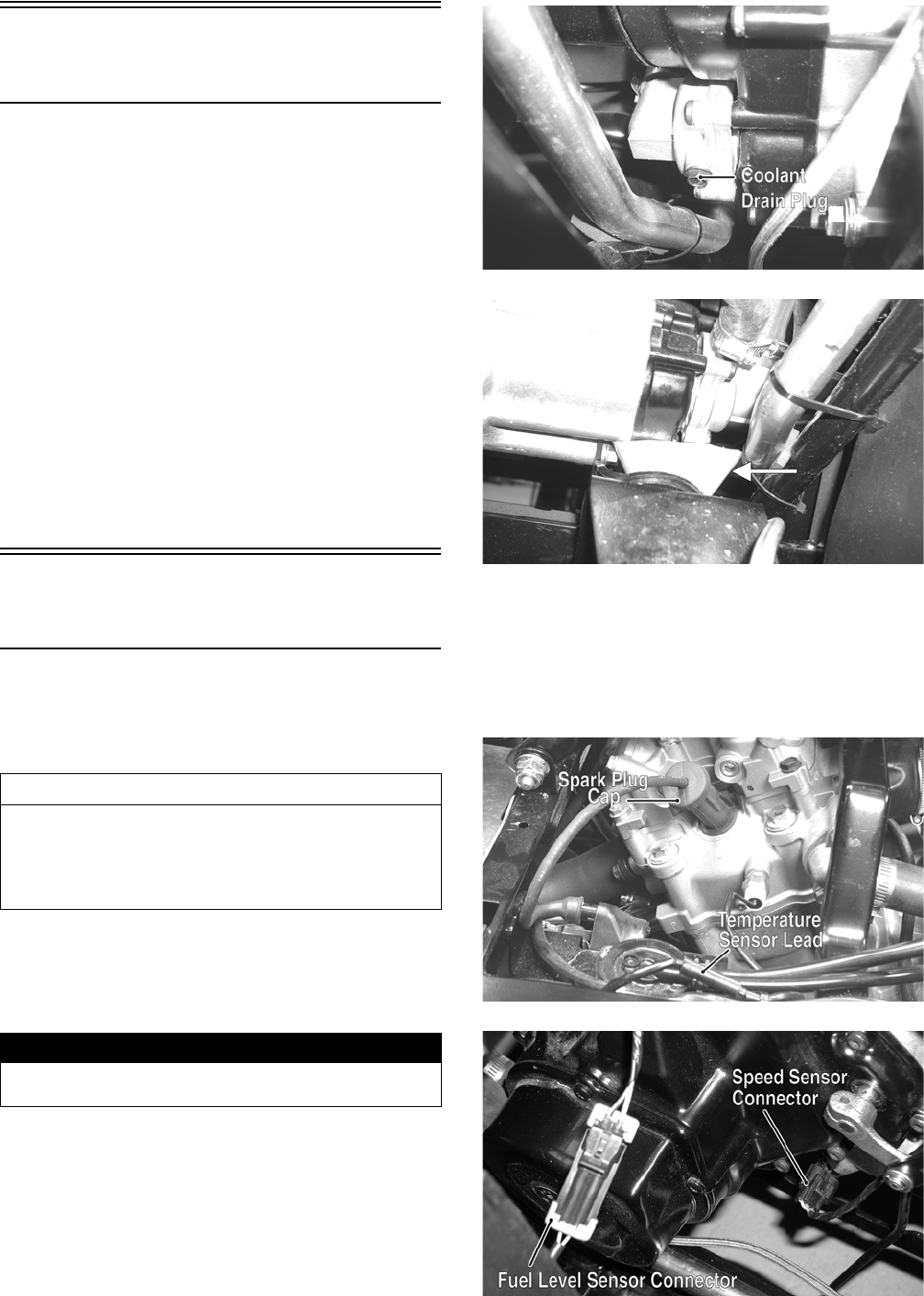
43
Prowler XT/XTX
(Table of Contents)
Removing Engine/ Transmission..................................... 43
Top-Side Components .................................................... 46
Removing Top-Side Components ................................... 46
Servicing Top-Side Components..................................... 50
Installing Top-Side Components ..................................... 57
Right-Side Components.................................................. 61
Removing Right-Side Components................................. 62
Servicing Right-Side Components .................................. 64
Installing Right-Side Components................................... 65
Left-Side Components .................................................... 68
Removing Left-Side Components ................................... 69
Servicing Left-Side Components ................................... 71
Installing Left-Side Components ..................................... 72
Center Crankcase Components...................................... 75
Separating Crankcase Halves......................................... 76
Disassembling Crankcase Half ....................................... 76
Servicing Center Crankcase Components...................... 78
Assembling Crankcase Half ............................................ 83
Joining Crankcase Halves............................................... 84
Installing Engine/Transmission........................................ 85
Removing Engine/
Transmission
Many service procedures can be performed without
removing the engine/transmission from the frame.
Closely observe the note introducing each sub-section for
this important information.
Support the vehicle on a suitable lift or jack stands allow-
ing room to perform work from the underside.
NOTE: Locate the jack stands to allow removing of
the center belly panel.
1. Remove the seats and center console; then remove
the left-side and right-side seat-bases.
2. Remove the center belly panel; then drain the oil and
coolant.
NOTE: Use a small funnel between the frame and
coolant drain plug to prevent coolant from draining
on the frame and splashing.
PR122A
PR156A
3. Remove the negative cable from the battery; then
remove the positive cable.
4. From the right-side, remove the spark plug cap; then
disconnect the temperature sensor lead, speed sensor
connector, fuel level sensor connector, and reverse
override switch connector.
PR130A
PR155A
AT THIS POINT
If the technician’s objective is to service/replace
left-side cover oil seals, front output joint oil seal, rear
output joint oil seal, and/or the oil strainer (from
beneath the engine/transmission), the engine/transmis-
sion does not have to be removed from the frame.
! WARNING
Make sure the vehicle is solidly supported on the sup-
port stands to avoid injury.
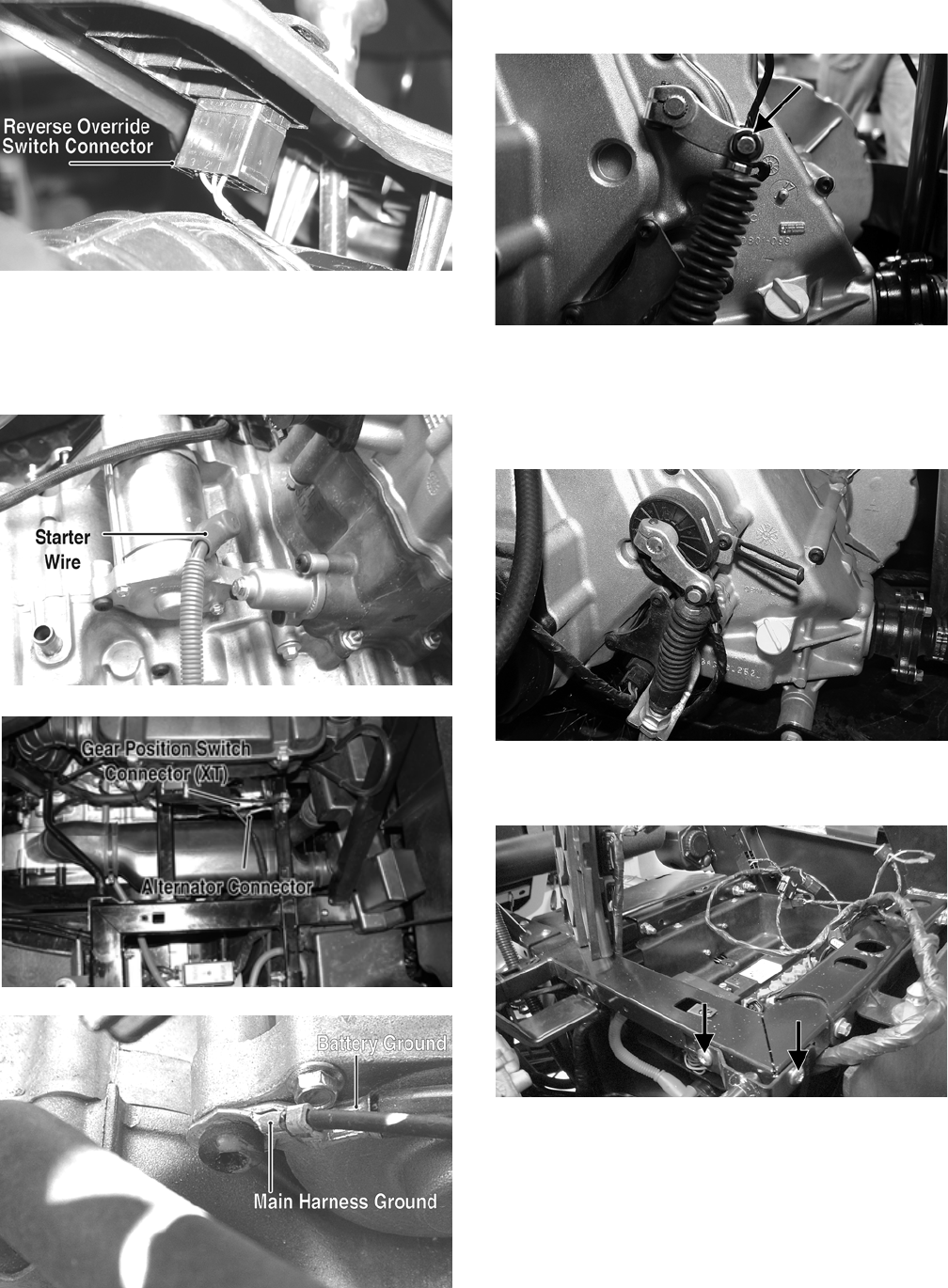
44
PR157A
5. From the left-side, disconnect the starter wire, alter-
nator connector, and gear position switch connector
(XT); then remove the cap screw securing the main
harness ground and the battery ground wires to the
starter.
PR145A
PR266C
PR474B
6. On the XT, remove the E-clip from the transmission
shift arm; then disconnect the cable.
PR567A
7. On the XTX, remove the cap screws securing the
shift cable bracket to the engine case. Remove the
cap screw from the shift arm and disconnect the gear
position switch connector. Slide the gear position
switch off the engine.
HDX251
8. Remove four machine screws securing the shifter
mount to the frame; then remove the shifter assembly.
PR596A
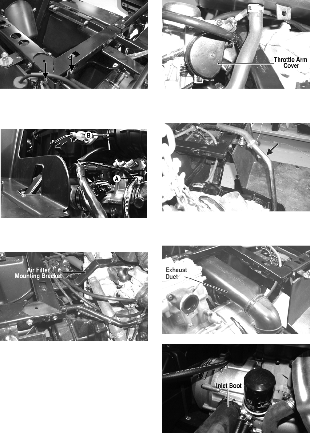
45
PR598A
9. Loosen the clamp (A) securing the air intake boot to
the throttle body and the clamp (B) securing the air
filter housing to the inlet housing boot; then remove
the crankcase breather hose from the crankcase.
PR578A
10. Remove two self-tapping screws securing the air fil-
ter mounting bracket to the frame; then remove the
air filter and mounting bracket as an assembly.
PR140A
11. Remove the throttle arm cover from the throttle
body; then disconnect and remove the throttle cable
and the throttle body.
PR154A
12. Remove the coolant hoses from the water pump and
thermostat housings; then position the upper coolant
line to the left-side of the engine compartment.
PR150A
13. Remove the exhaust duct from the V-belt housing;
then remove the inlet boot connecting the inlet duct
to the V-belt housing.
PR144B
HDX140A
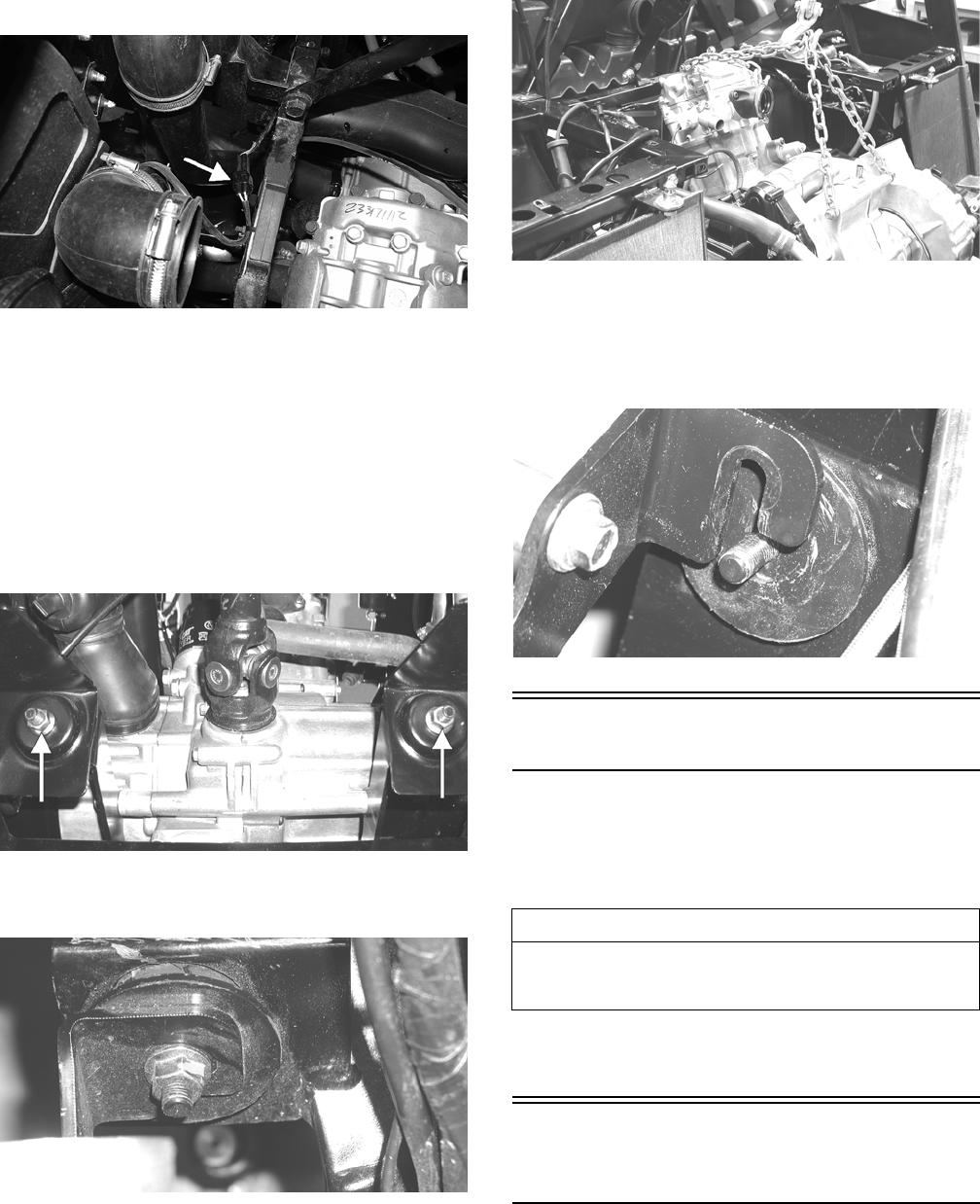
46
14. Disconnect the O2 sensor; then remove the O2 sensor.
PR859A
15. Remove the muffler; then remove the exhaust pipe.
16. Set the parking brake; then from the underside of the
vehicle, remove the cap screws securing the drive-
shafts to the drive couplers.
NOTE: Remove the front driveshaft first or the park-
ing brake will not hold the coupler stationary and cap
screw removing will be more difficult.
17. Remove two flange nuts from the underside of the
rear engine mounts.
PR153A
18. Remove two flange nuts securing the engine mounting
bracket to the front engine mounts.
PR147
19. Attach suitable lifting chains to the engine/transmission;
then using an engine hoist, lift the assembly out of the
engine compartment.
PR114
NOTE: The front engine mounting bracket should slide
free of the engine mounts first; then the rear engine
mounting bracket and two rear engine mounts will lift
free of the frame.
PR146
Top-Side Components
NOTE: For efficiency, it is preferable to remove and dis-
assemble only those components which need to be
addressed and to service only those components. The
technician should use discretion and sound judgment.
NOTE: The engine/transmission does not have to
removed from the frame for this procedure.
Removing Top-Side
Components
A. Valve Cover/Rocker Arms
B. Cylinder Head/Camshaft
NOTE: Remove the spark plug and timing inspec-
tion plug; then using a socket and ratchet, rotate the
crankshaft to top-dead-center of the compression
stroke.
AT THIS POINT
To service any one specific component, only limited dis-
assembly of components may be necessary. Note the
AT THIS POINT information in each sub-section.
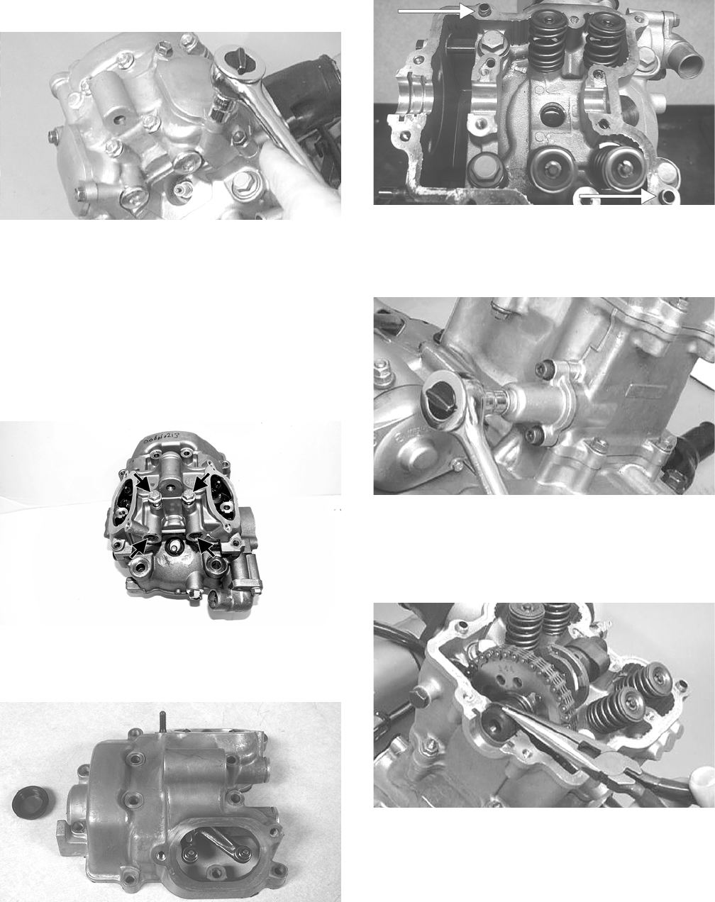
47
1. Remove the two tappet covers.
CC001D
NOTE: Keep the mounting hardware with the covers
for assembly purposes or thread them back into the
head to keep them separated.
2. Loosen the twelve cap screws securing the valve
cover to the head.
3. Remove all cap screws except the two top-side cap
screws next to the spark plug. These will keep the
alignment pins in place. Note the two rubber washers
on the remaining cap screws.
H1-013A
4. Remove the valve cover. Account for and note the
orientation of the cylinder head plug. Note the loca-
tion of the two alignment pins.
CD206
CD211A
5. Loosen the cap screw on the end of the tensioner;
then remove the two cap screws securing the ten-
sioner adjuster assembly and remove the assembly.
Account for a gasket.
CC009D
6. Using an awl, rotate the C-ring in its groove until it is
out of the cylinder head; then remove the C-ring.
NOTE: Care should be taken not to drop the C-ring
down into the crankcase.
CC012D
7. Bend the washer tabs down and remove the two cap
screws securing the sprocket to the camshaft; then
drop the sprocket off the camshaft.
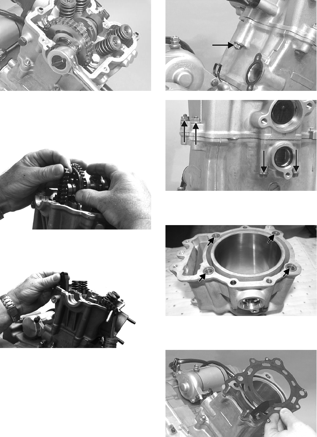
48
CC013D
8. While holding the chain, slide the sprocket and cam-
shaft out of the cylinder head.
NOTE: Loop the chain over the cylinder and secure
it to keep it from falling into the crankcase.
FI620
9. Remove the cap screw securing the chain tensioner
(account for a washer); then remove the tensioner.
FI617
10. Remove the five nuts securing the cylinder head to
the cylinder.
CC017D
CC018D
11. Remove the four cylinder head bolts.
NOTE: On the 700, account for rubber O-rings.
H1-016A
12. Remove the cylinder head from the cylinder, remove the
gasket, and account for two alignment pins; then remove
the cam chain guide.
CC020D
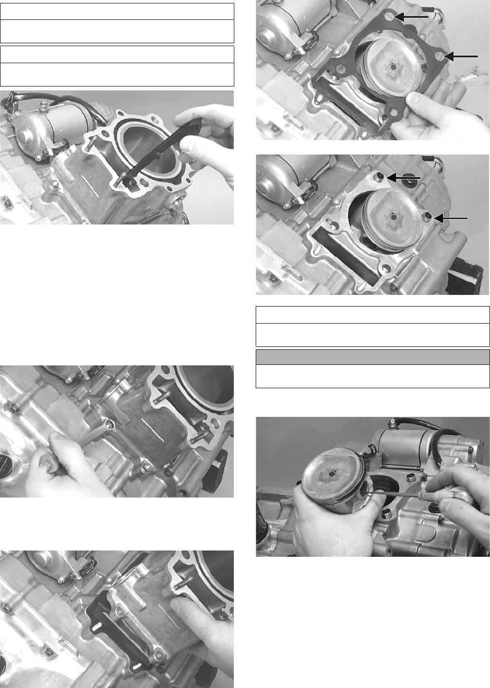
49
CC022D
C. Cylinder
D. Piston
NOTE: Steps 1-12 in the preceding sub-section
must precede this procedure.
13. Loosen the clamp securing the coolant hose to the union;
then detach the hose.
14. Remove the two nuts securing the cylinder to the crank-
case.
CC023D
15. Lift the cylinder off the crankcase taking care not to
allow the piston to drop against the crankcase. Account
for the gasket and two alignment pins.
CC024D
CC025D
CC026D
16. Using an awl, remove one piston-pin circlip.
CC032D
17. Using the Piston Pin Puller, remove the piston pin.
Account for the opposite-side circlip. Remove the
piston.
NOTE: It is advisable to remove the opposite-side
circlip prior to using the puller.
AT THIS POINT
To service valves and cylinder head, see Servicing
Top-Side Components sub-section.
AT THIS POINT
To inspect cam chain guide, see Servicing Top-Side
Components sub-section.
AT THIS POINT
To service cylinder, see Servicing Top-Side Compo-
nents sub-section.
CAUTION
When removing the cylinder, be sure to support the pis-
ton to prevent damage to the crankcase and piston.
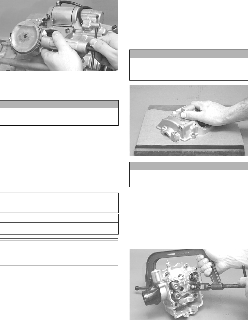
50
CC033D
NOTE: Support the connecting rod with rubber
bands to avoid damaging the rod or install the Con-
necting Rod Holder.
NOTE: If the existing rings will not be replaced with
new rings, note the location of each ring for proper
installation. When replacing with new rings, replace
as a complete set only. If the piston rings must be
removed, remove them in this sequence.
A. Starting with the top ring, slide one end of the ring
out of the ring-groove.
B. Remove each ring by working it toward the dome
of the piston while rotating it out of the groove.
Servicing Top-Side
Components
VALVE ASSEMBLY
When servicing valve assembly, inspect valve seats,
valve stems, valve faces, and valve stem ends for pits,
burn marks, or other signs of abnormal wear.
NOTE: Whenever a valve is out of tolerance, it must
be replaced.
Cleaning/Inspecting Valve Cover
NOTE: If the valve cover cannot be trued, the cylin-
der head assembly must be replaced.
1. Wash the valve cover in parts-cleaning solvent.
2. Place the valve cover on the Surface Plate covered
with #400 grit wet-or-dry sandpaper. Using light
pressure, move the valve cover in a figure eight
motion. Inspect the sealing surface for any indication
of high spots. A high spot can be noted by a bright
metallic finish. Correct any high spots before assem-
bly by continuing to move the valve cover in a figure
eight motion until a uniform bright metallic finish is
attained.
CC130D
Removing Valves
NOTE: Index all valves, springs, and cotters to their
original position when removing. When installing, all
valve components should be installed in their original
position.
1. Using a valve spring compressor, compress the valve
springs and remove the valve cotters. Account for an
upper spring retainer.
CC132D
2. Remove the valve seal and the lower remaining
spring seat. Discard the valve seal.
CAUTION
Do not allow the connecting rod to go down inside the
crankcase. If the rod is down inside the crankcase and
the crankshaft is rotated, severe damage will result.
AT THIS POINT
To service piston, see Servicing Top-Side Components
sub-section.
AT THIS POINT
To service center crankcase components only, proceed
to Removing Left-Side Components.
CAUTION
Do not remove an excessive amount of the sealing sur-
face or damage to the camshaft will result. Always
check camshaft clearance when resurfacing the valve
cover.
CAUTION
Water or parts-cleaning solvent must be used in con-
junction with the wet-or-dry sandpaper or damage to
the sealing surface may result.
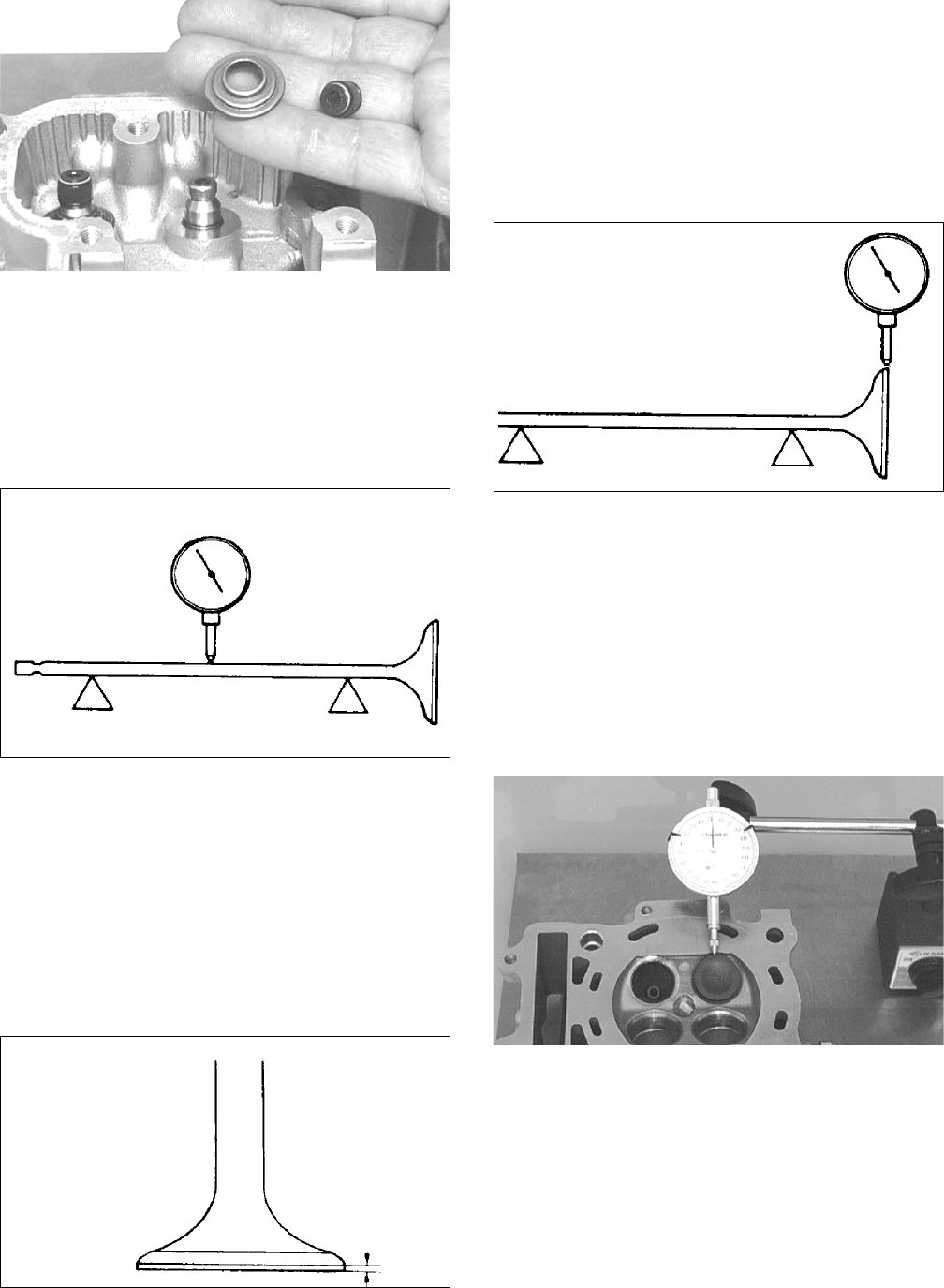
51
CC136D
NOTE: The valve seals must be replaced.
3. Remove the valve springs; then invert the cylinder
head and remove the valves.
Measuring Valve Stem Runout
1. Support each valve stem end with the V Blocks; then
check the valve stem runout using a dial indicator.
ATV-1082
2. Maximum runout must not exceed specifications.
Measuring Valve Stem Outside
Diameter
1. Using a micrometer, measure the valve stem outside
diameter.
2. Acceptable diameter range must be within specifications.
Measuring Valve Face/Seat Width
1. Using a micrometer, measure the width of the valve face.
ATV-1004
2. Acceptable width ranges must not exceed specifica-
tions.
Measuring Valve Face Radial
Runout
1. Mount a dial indicator on the surface plate; then
place the valve stem on a set of V blocks.
2. Position the dial indicator contact point on the out-
side edge of the valve face; then zero the indicator.
ATV1082A
3. Rotate the valve in the V blocks.
4. Maximum runout must not exceed specifications.
Measuring Valve Guide/Valve Stem
Deflection (Wobble Method)
1. Mount a dial indicator and base on the surface plate;
then place the cylinder head on the surface plate.
2. Install the valve into the cylinder head; then position
the dial indicator contact point against the outside
edge of the valve face. Zero the indicator.
CC131D
3. Push the valve from side to side; then from top to
bottom.
4. Maximum “wobble” deflection must not exceed
specifications.
Measuring Valve Guide
(Inside Diameter)
1. Insert a snap gauge 1/2 way down into each valve
guide bore; then remove the gauge and measure it
with a micrometer.
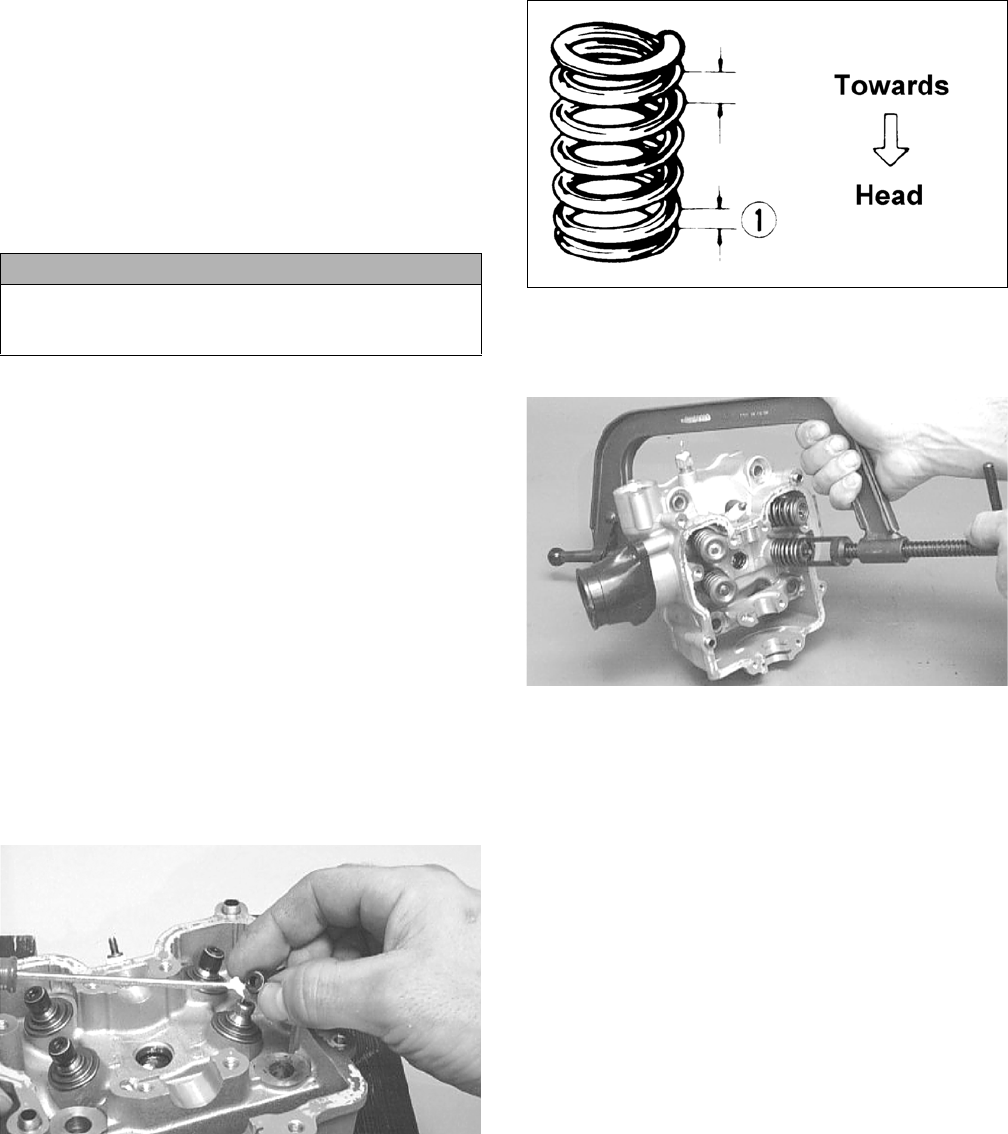
52
2. Acceptable inside diameter range must be within
specifications.
3. If a valve guide is out of tolerance, it must be
replaced.
Servicing Valves/Valve
Guides/Valve Seats
If valves, valve guides, or valve seats require servicing or
replacement, Arctic Cat recommends that the compo-
nents be taken to a qualified machine shop for servicing.
Measuring Rocker Arm
(Inside Diameter)
1. Using a dial calipers, measure the inside diameter of
the rocker arm.
2. Acceptable inside diameter range must be within
specifications.
Measuring Rocker Arm Shaft
(Outside Diameter)
1. Using a micrometer, measure the outside diameter of
the rocker arm shaft.
2. Acceptable outside diameter range must be within
specifications.
Installing Valves
1. Apply grease to the inside surface of the valve seals;
then place a lower spring seat and valve guide seal
over each valve guide.
CC144D
2. Insert each valve into its original location.
3. Install the valve springs with the painted end of the
spring facing away from the cylinder head.
NOTE: If the paint is not visible, install the ends of
the springs with the closest wound coils toward the
head.
ATV-1011A
4. Place a spring retainer over the valve springs; then
using the valve spring compressor, compress the
valve springs and install the valve cotters.
CC132D
PISTON ASSEMBLY
NOTE: Whenever a piston, rings, or pin are out of
tolerance, they must be replaced.
Cleaning/Inspecting Piston
1. Using a non-metallic carbon removal tool, remove
any carbon buildup from the dome of the piston.
2. Inspect the piston for cracks in the piston pin, dome,
and skirt areas.
3. Inspect the piston for seizure marks or scuffing.
Repair with #400 grit wet-or-dry sandpaper and
water or honing oil.
NOTE: If scuffing or seizure marks are too deep to
correct with the sandpaper, replace the piston.
4. Inspect the perimeter of each piston for signs of
excessive “blowby.” Excessive “blowby” indicates
worn piston rings or an out-of-round cylinder.
Removing Piston Rings
1. Starting with the top ring, slide one end of the ring
out of the ring-groove.
CAUTION
If valves are discolored or pitted or if the seating sur-
face is worn, the valve must be replaced. Do not attempt
to grind the valves or severe engine damage may occur.
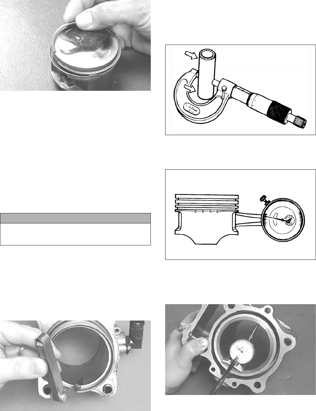
53
CC400D
2. Remove each ring by working it toward the dome of
the piston while rotating it out of the groove.
NOTE: If the existing rings will not be replaced with
new ones, note the location of each ring for proper
installation. When installing new rings, install as a
complete set only.
Cleaning/Inspecting Piston Rings
1. Take an old piston ring and snap it into two pieces;
then grind the end of the old ring to a 45° angle and
to a sharp edge.
2. Using the sharpened ring as a tool, clean carbon from
the ring-grooves. Be sure to position the ring with its
tapered side up.
Measuring Piston-Ring End Gap
(Installed)
1. Place each compression ring in the wear portion of
the cylinder. Use the piston to position each ring
squarely in the cylinder.
2. Using a feeler gauge, measure each piston-ring end
gap. Acceptable ring end gap must not exceed speci-
fications.
CC280D
Measuring Piston Pin (Outside
Diameter) and Piston-Pin Bore
1. Measure the piston pin outside diameter at each end
and in the center. If measurement is not within speci-
fications, the piston pin must be replaced.
ATV-1070
2. Insert an inside dial indicator into the piston-pin
bore. The diameter must not exceed specifications.
Take two measurements to ensure accuracy.
ATV-1069
Measuring Piston Skirt/Cylinder
Clearance
1. Measure the cylinder front to back in six places.
CC127D
2. Measure the corresponding piston diameter at the
recommended point above the piston skirt at a right
angle to the piston-pin bore. Subtract this measure-
ment from the measurement in step 1. The difference
(clearance) must not exceed specifications.
CAUTION
Improper cleaning of the ring-grooves by the use of the
wrong type of ring-groove cleaner will result in severe
damage to the piston.
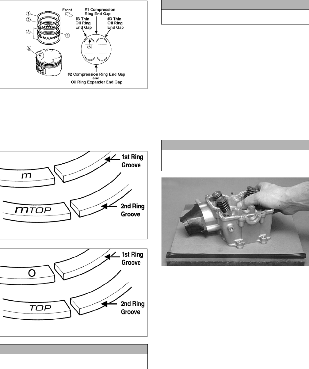
54
Installing Piston Rings
1. Install ring expander (4) in the bottom groove of the
piston; then install the thin oil rings (3) over the
expander making sure the expander ends do not
overlap. Stagger the end gaps of the upper and lower
thin oil rings according to the illustration.
ATV-1085B
NOTE: Note the direction of the exhaust side of the
piston (5) for correct ring end gap orientation.
2. The ring with the orientation mark (MTOP or TOP)
should be installed in the second (middle) groove
and the ring with the orientation mark (M or O)
should be installed in the first (top) groove.
ATV-1024A
ATV-1024B
CYLINDER/CYLINDER HEAD
ASSEMBLY
NOTE: If the cylinder/cylinder head cannot be trued,
they must be replaced as an assembly.
Cleaning/Inspecting Cylinder Head
1. Using a non-metallic carbon removal tool, remove
any carbon buildup from the combustion chamber
being careful not to nick, scrape, or damage the com-
bustion chamber or the sealing surface.
2. Inspect the spark plug hole for any damaged threads.
Repair damaged threads using a “heli-coil” insert.
3. Place the cylinder head on the Surface Plate covered
with #400 grit wet-or-dry sandpaper. Using light
pressure, move the cylinder head in a figure eight
motion. Inspect the sealing surface for any indication
of high spots. A high spot can be noted by a bright
metallic finish. Correct any high spots before assem-
bly by continuing to move the cylinder head in a fig-
ure eight motion until a uniform bright metallic
finish is attained.
CC128D
Measuring Cylinder Head
Distortion
1. Remove any carbon buildup in the combustion
chamber.
2. Lay a straightedge across the cylinder head; then
using a feeler gauge, check the distortion factor
between the head and the straightedge.
3. Maximum distortion must not exceed specifications.
CAUTION
Incorrect installation of the piston rings will result in
engine damage.
CAUTION
The cylinder head studs must be removed for this pro-
cedure.
CAUTION
Water or parts-cleaning solvent must be used in con-
junction with the wet-or-dry sandpaper or damage to
the sealing surface may result.
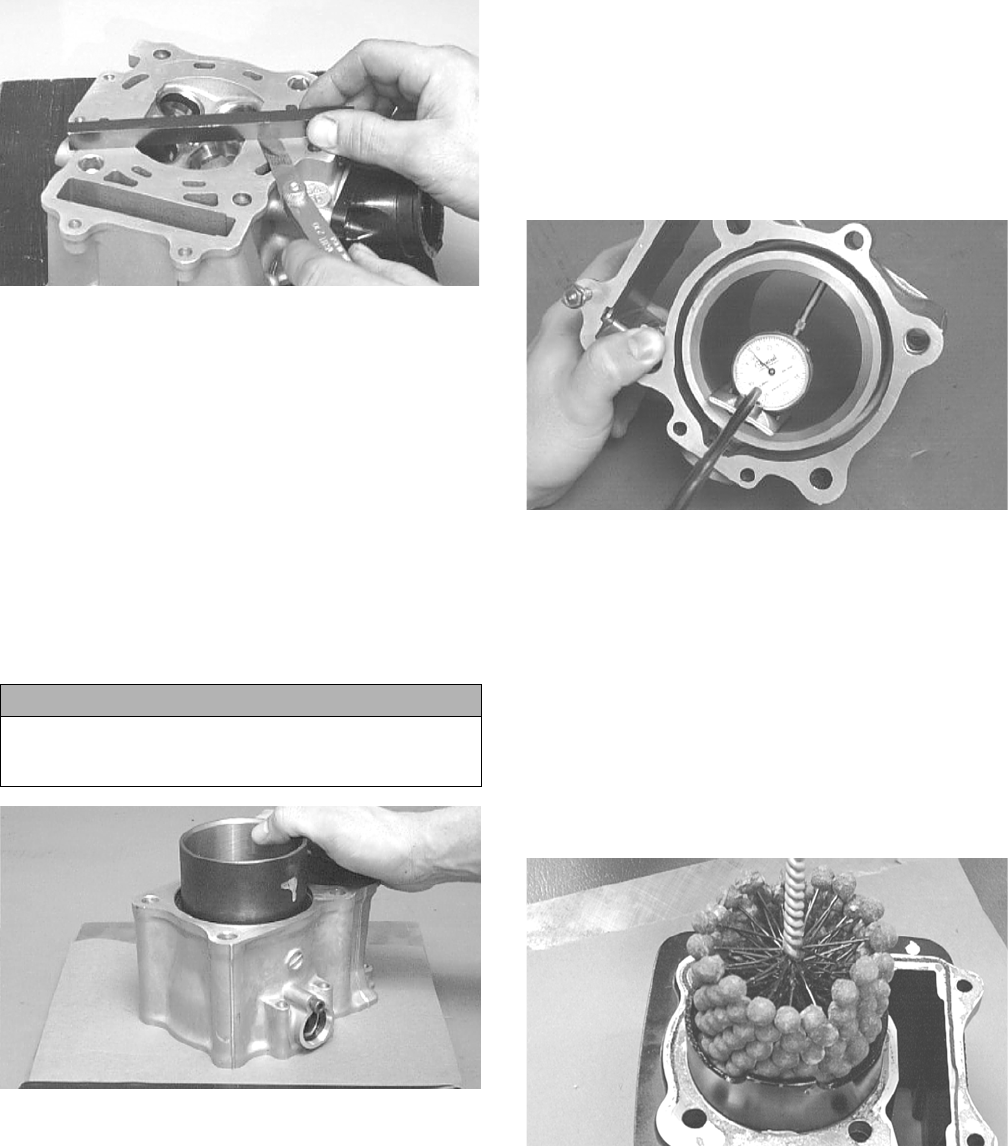
55
CC141D
Cleaning/Inspecting Cylinder
1. Wash the cylinder in parts-cleaning solvent.
2. Inspect the cylinder for pitting, scoring, scuffing, warp-
age, and corrosion. If marks are found, repair the surface
using a cylinder hone (see Inspecting Cylinder in this
sub-section).
3. Place the cylinder on the surface plate covered with
#400 grit wet-or-dry sandpaper. Using light pressure,
move the cylinder in a figure eight motion. Inspect
the sealing surface for any indication of high spots.
A high spot can be noted by a bright metallic finish.
Correct any high spots before assembly by continu-
ing to move the cylinder in a figure eight motion
until a uniform bright metallic finish is attained.
CC129D
Inspecting Cam Chain Guide
1. Inspect cam chain guide for cuts, tears, breaks, or chips.
2. If the chain guide is damaged, it must be replaced.
Inspecting Cylinder
1. Using a slide gauge and a dial indicator or a snap
gauge, measure the cylinder bore diameter in three
locations from top to bottom and again from top to
bottom at 90° from the first measurements for a total
of six measurements. The trueness (out-of-round-
ness) is the difference between the highest and low-
est reading. Maximum trueness (out-of-roundness)
must not exceed specifications.
CC127D
2. Wash the cylinder in parts-cleaning solvent.
3. Inspect the cylinder for pitting, scoring, scuffing, and
corrosion. If marks are found, repair the surface
using a #320 grit ball hone.
NOTE: To produce the proper 60° cross-hatch pat-
tern, use a low RPM drill (600 RPM) at the rate of 30
strokes per minute. If honing oil is not available, use
a lightweight petroleum-based oil. Thoroughly clean
cylinder after honing using soap and hot water. Dry
with compressed air; then immediately apply oil to
the cylinder bore. If the bore is severely damaged or
gouged, replace the cylinder.
CC390D
4. If any measurement exceeds the limit, replace the
cylinder and piston.
Measuring Camshaft Runout
NOTE: If the camshaft is out of tolerance, it must be
replaced.
1. Place the camshaft on a set of V blocks; then position
the dial indicator contact point against the shaft and
zero the indicator.
CAUTION
Water or parts-cleaning solvent must be used in con-
junction with the wet-or-dry sandpaper or damage to
the sealing surface may result.
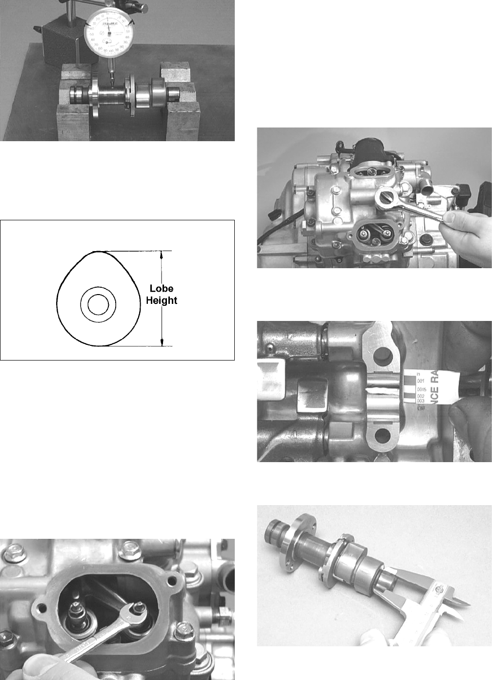
56
CC283D
2. Rotate the camshaft and note runout; maximum run-
out must not exceed specifications.
Measuring Camshaft Lobe Height
1. Using a calipers, measure each cam lobe height.
ATV1013A
2. The lobe heights must be greater than minimum
specifications.
Inspecting Camshaft Bearing
Journal
1. Inspect the bearing journal for scoring, seizure
marks, or pitting.
2. If excessive scoring, seizure marks, or pitting is
found, the cylinder head assembly must be replaced.
Measuring Camshaft to Cylinder
Head Clearance
1. Remove the adjuster screws and jam nuts.
CC005D
2. Place a strip of plasti-gauge in each of the camshaft
lands in the cylinder head.
3. Place the valve cover on the cylinder head and secure
with the valve cover cap screws. Tighten securely.
NOTE: Do not rotate the camshaft when measuring
clearance.
4. Remove the cap screws securing the valve cover to
the cylinder; then remove the valve cover and cam-
shaft.
CC003D
5. Match the width of the plasti-gauge with the chart
found on the plasti-gauge packaging to determine
camshaft to cylinder head and valve cover clearance.
CC145D
6. If clearance is excessive, measure the journals of the
camshaft.
CC287D
NOTE: If the journals are worn, replace the cam-
shaft; then measure the clearance again. If it is still
out of tolerance, replace the cylinder head.
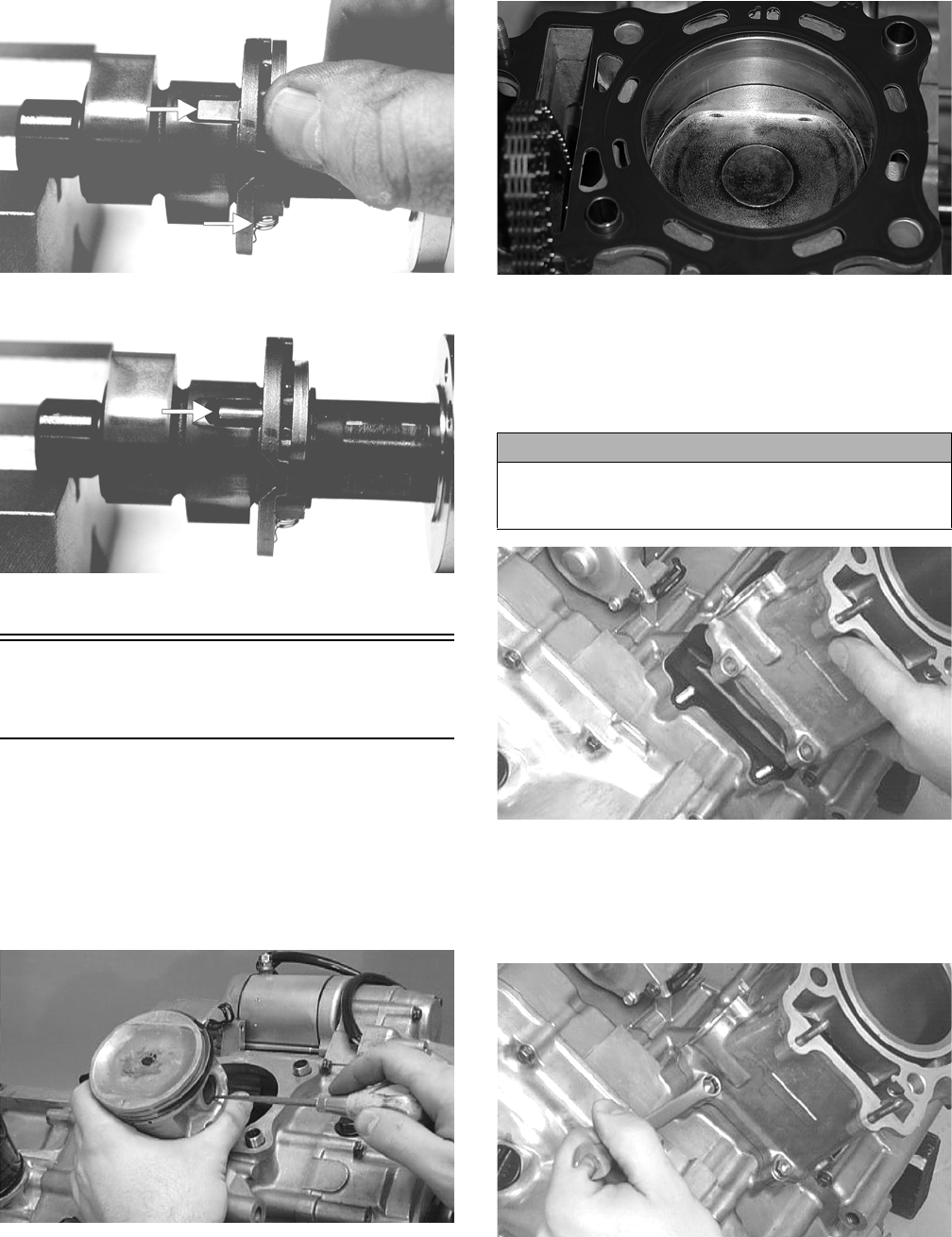
57
Inspecting Camshaft Spring/Drive
Pin
1. Inspect the spring and drive pin for damage.
CF061A
CF060A
2. If damaged, the camshaft must be replaced.
Installing Top-Side
Components
A. Piston
B. Cylinder
1. Install the piston on the connecting rod making sure
the circlip on each side is fully seated in the piston.
NOTE: The piston should be installed so the arrow
points toward the exhaust.
CC032D
2. Place the two alignment pins into position. Place the
cylinder gasket into position; then place a piston
holder (or suitable substitute) beneath the piston skirt
and square the piston in respect to the crankcase.
CF083
3. Lubricate the inside wall of the cylinder; then using a
ring compressor or the fingers, compress the rings
and slide the cylinder over the piston. Route the cam
chain up through the cylinder cam chain housing;
then remove the piston holder and seat the cylinder
firmly on the crankcase.
CC024D
4. Loosely install the two nuts which secure the cylin-
der to the crankcase.
NOTE: The two cylinder-to-crankcase nuts will be
tightened in step 11.
CC023D
CAUTION
The cylinder should slide on easily. Do not force the cyl-
inder or damage to the piston, rings, cylinder, or crank-
shaft assembly may occur.
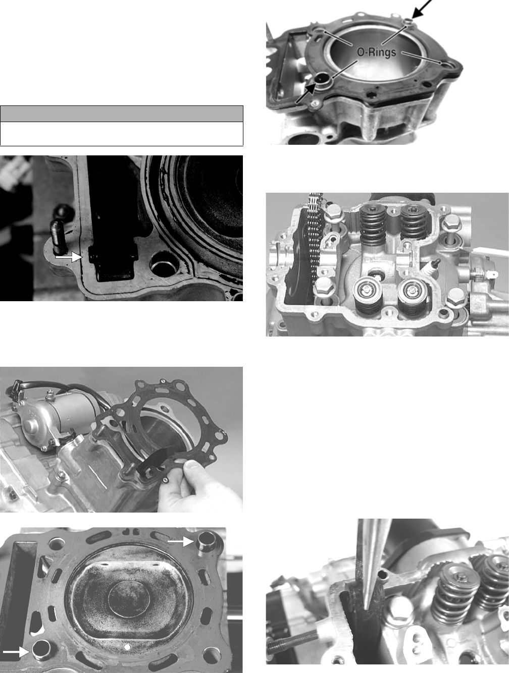
58
5. Install the coolant hose onto the crankcase union and
tighten the clamp.
C. Cylinder Head
D. Valve Cover
NOTE: Steps 1-5 in the preceding sub-section must
precede this procedure.
6. Place the chain guide into the cylinder.
CF058A
7. Place a new head gasket into position on the cylin-
der. Place the alignment pins and four O-rings (700
only) into position; then place the head assembly into
position on the cylinder.
CC020D
CF057A
CF289A
8. Install the four cylinder head cap screws and wash-
ers. Tighten only until snug.
CC272D
9. Loosely install the five cylinder head nuts.
10. Using a crisscross pattern, tighten the four cap
screws (from step 8) initially to 20 ft-lb; then in 10
ft-lb increments, tighten to a final torque of 40 ft-lb.
11. Tighten the 8 mm nuts from step 9 to 21 ft-lb and the
6 mm nuts to 8.5 ft-lb; then tighten the two cylin-
der-to-crankcase nuts (from step 4) securely.
12. With the timing inspection plug removed and the
chain held tight, rotate the crankshaft until the piston
is at top-dead-center.
13. Install the rear cam chain tensioner guide into the
cylinder head. Install the pivot cap screw and washer.
CD461
NOTE: At this point, oil the camshaft journals, cam
lobes, and the three seating surfaces on the cylinder.
CAUTION
Care should be taken that the bottom of the chain guide
is secured in the crankcase boss.
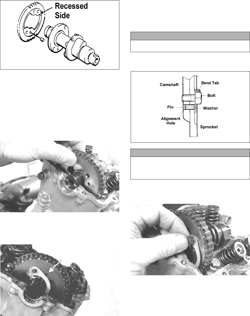
59
14. With the alignment pin installed in the camshaft, loosely
place the cam sprocket (with the recessed side facing the
cam shaft lobes) onto the camshaft. At this point, do not
“seat” the sprocket onto the shaft.
732-307B
15. With the cam lobes directed down (toward the pis-
ton), maneuver the camshaft/sprocket assembly
through the chain and towards its seating position;
then loop the chain over the sprocket.
NOTE: Note the position of the alignment marks on
the end of the camshaft. They must be parallel with
the valve cover mating surface. If rotating the cam-
shaft and sprocket is necessary for alignment, do not
allow the crankshaft to rotate and be sure the cam
lobes end up in the down position.
CD463
16. Seat the cam sprocket onto the camshaft making sure the
alignment pin in the camshaft aligns with the smallest
hole in the sprocket; then place the camshaft/sprocket
assembly onto the cylinder ensuring the following.
CF013A
A. Piston still at top-dead-center.
B. Camshaft lobes directed down (toward the pis-
ton).
C. Camshaft alignment marks parallel to the valve
cover mating surface.
D. Recessed side of the sprocket directed toward the
cam lobes.
E. Camshaft alignment pin and sprocket alignment
hole (smallest) are aligned.
17. Place the tab-washer onto the sprocket making sure it
covers the pin in the alignment hole.
ATV1027
18. Install the first cap screw (threads coated with red
Loctite #271) securing the sprocket and tab-washer
to the camshaft. Tighten only until snug.
CD464
19. Rotate the crankshaft until the second cap screw
securing the sprocket to the camshaft can be
installed; then install the cap screw (threads coated
with red Loctite #271) and tighten to 10 ft-lb. Bend
the tab to secure the cap screw.
CAUTION
If any of the above factors are not as stated, go back to
step 12 and carefully proceed.
CAUTION
Care must be taken that the tab-washer is installed cor-
rectly to cover the alignment hole on the sprocket. If the
alignment pin falls out, severe engine damage will
result.
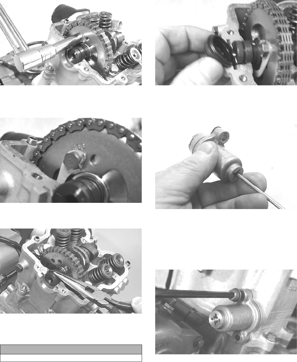
60
CD465
20. Rotate the crankshaft until the first cap screw (from
step 18) can be accessed; then tighten to 10 ft-lb.
Bend the tab to secure the cap screw.
CD466
21. Place the C-ring into position in its groove in the cyl-
inder head.
CC012D
22. Install the cylinder head plug in the cylinder head
with the open end facing downward and toward the
inside.
CD468
23. Remove the cap screw from the end of the chain ten-
sioner; then using a flat-blade screwdriver, rotate the
adjuster screw inside the tensioner clockwise until
the screw bottoms.
CD501
NOTE: The adjuster shaft will be drawn into the ten-
sioner as the adjuster screw is rotated clockwise. The
adjuster shaft tension will be released in step 25.
24. Place the chain tensioner adjuster assembly and gas-
ket into position on the cylinder and secure with the
two cap screws.
CD469
25. Using a flat-blade screwdriver, rotate the adjuster
screw inside the tensioner counterclockwise until all
tension is released; then install the cap screw into the
end of the chain tensioner.
CAUTION
The open end of the plug must be positioned downward.
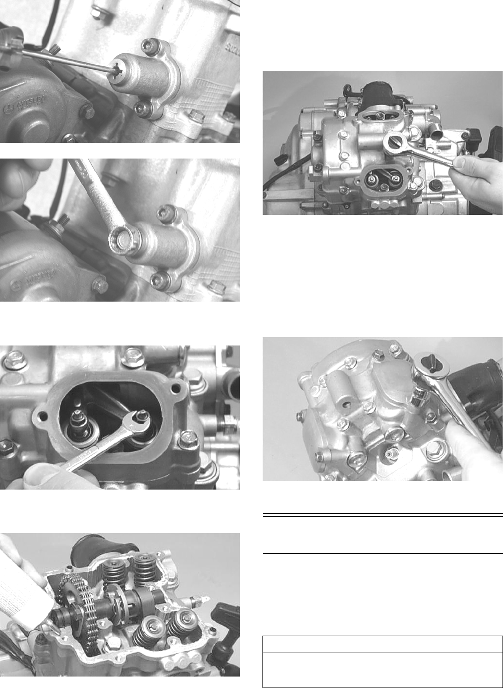
61
CD470
CD471
26. Loosen the four adjuster screw jam nuts; then loosen the
four adjuster screws on the rocker arms in the valve cover.
CC005D
27. Apply a thin coat of Three Bond Sealant to the mat-
ing surfaces of the cylinder head and valve cover.
CC275D
28. Place the valve cover into position.
NOTE: At this point, the rocker arms and adjuster
screws must not have pressure on them.
29. Install the four top side cap screws with rubber wash-
ers; then install the remaining cap screws. Tighten
only until snug.
CC003D
30. In a crisscross pattern starting from the center and
working outward, tighten the cap screws (from step
29) to 8.5 ft-lb.
31. Adjust valve/tappet clearance (see Periodic Mainte-
nance).
32. Place the two tappet covers into position making sure
the proper cap screws are with the proper cover.
Tighten to 8.5 ft lb.
CC001D
33. If removed, install the spark plug. Tighten securely.
Right-Side Components
NOTE: For efficiency, it is preferable to remove and
disassemble only those components which need to
be addressed and to service only those components.
The technician should use discretion and sound
judgment.
AT THIS POINT
To service any one specific component, only limited dis-
assembly of components may be necessary. Note the
AT THIS POINT information in each sub-section.
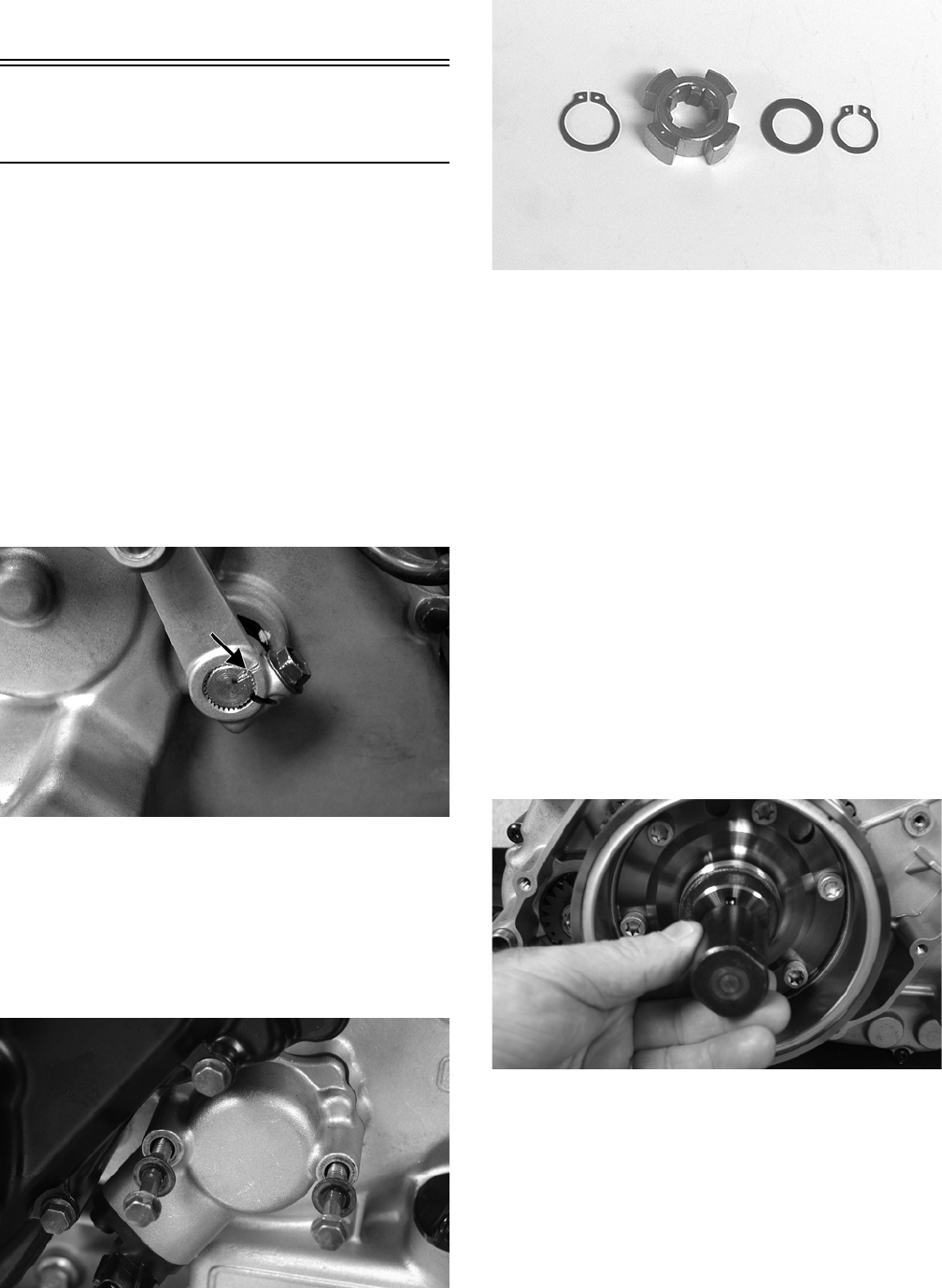
62
NOTE: The engine/transmission does not have to
be removed from the frame for this procedure.
Removing Right-Side
Components
A. Outer Magneto Cover
B. Water Pump
C. Cover
D. Rotor/Flywheel
1. Remove the four cap screws securing the outer mag-
neto cover to the right-side cover; then remove the
outer magneto cover.
2. Remove the flange nut securing the bushing to the
crankshaft; then remove the bushing. Account for the
O-ring inside the spacer.
3. On the XT using a cold chisel, scribe a mark show-
ing the relative position of the shift arm to the shift
arm shaft to aid in installing; then remove the shift
arm.
FI085A
4. Remove the cap screws securing the speed sensor
housing to the crankcase and remove the housing
assembly; then remove the snap ring securing the
speed sensor trigger to the shaft and remove the trig-
ger. Account for the gasket.
NOTE: It may be necessary to use a small two-jaw
puller to remove the trigger.
CD920
GZ254
5. Loosen the clamps securing the coolant hose to the
water pump; then remove the crossover tube from
the cylinder head. Account for an O-ring.
6. Remove the two cap screws securing the water pump
to the engine; then remove the water pump.
7. Remove the cap screws securing the right-side cover
to the crankcase noting the location of the differ-
ent-sized cap screws for installing purposes.
8. Using an appropriate side case puller, remove the
side cover. Account for a gasket and two alignment
pins.
9. Remove the nut securing the magneto rotor to the
crankshaft; then install the magneto rotor puller
adapter.
NOTE: The puller has left-hand threads.
10. Using Magneto Rotor Remover Set and the appropri-
ate crankshaft protector, remove the rotor/flywheel
assembly from the crankshaft. Account for the key;
then remove the starter clutch gear assembly and
washer.
PR441
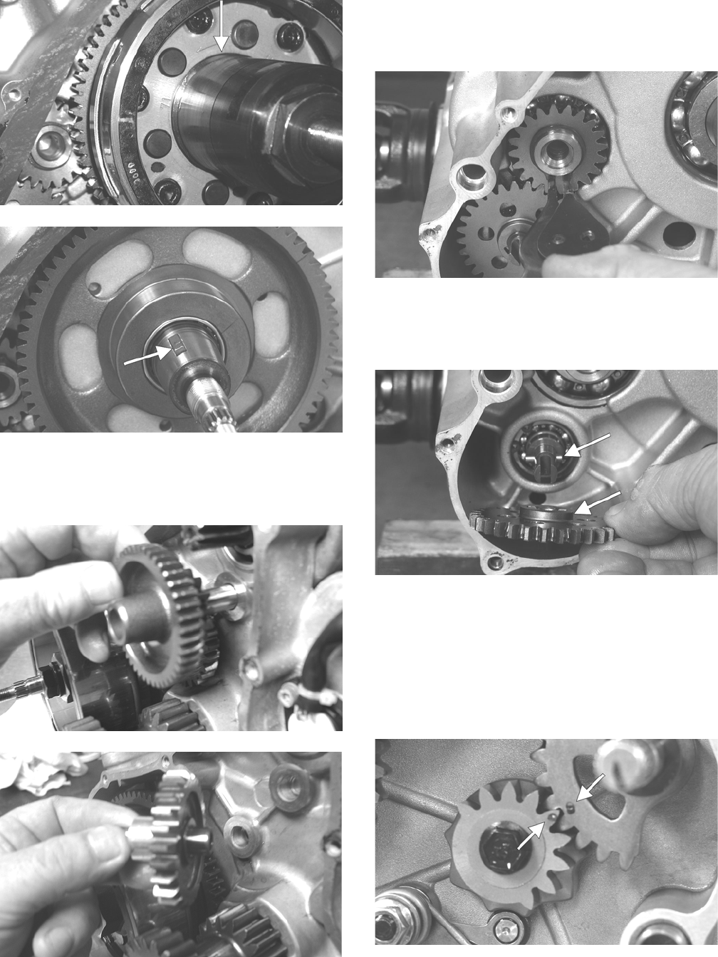
63
CD939A
CD940A
11. Remove the two starter gears from the crankcase not-
ing the direction of the beveled side of the gears for
installing purposes; then remove the two starter gear
shafts.
CD136
CD140
12. Remove the snap ring securing the water pump drive
gear; then remove the gear noting the direction of the
sides of the gear for installing purposes. Account for
the drive gear alignment pin.
CD944
13. Remove the snap ring securing the water pump
driven gear; then remove the gear noting the direc-
tion of the sides of the gear for installing purposes.
Account for the driven gear alignment pin.
CD952A
NOTE: There is an oil passage beneath the driven
gear/drive gear assembly. This passage should be
plugged prior to removing the driven gear and drive
gear. Failure to do so could result in the loss of an
alignment pin into the crankcase.
14. Remove the shift shaft noting the timing marks for
assembling purposes. Account for two washers.
PR430A
15. Remove the gear shift cam plate and account for a
washer; then remove the cam stopper and cam stop-
per spring. Account for two washers.
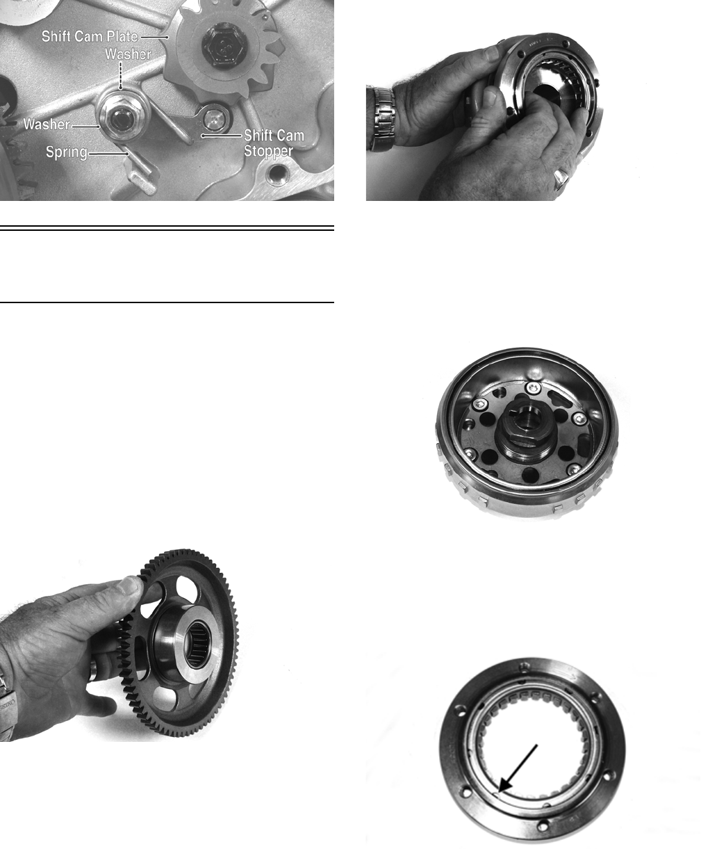
64
PR434A
Servicing Right-Side
Components
INSPECTING STARTER
CLUTCH/GEAR
1. Place the starter clutch gear onto the rotor/flywheel
and attempt to rotate the starter clutch gear clock-
wise. It should lock up to the rotor/flywheel. Rotate
the gear counterclockwise and it should turn freely. If
it moves or locks up both ways, the starter clutch
must be replaced.
2. Inspect the starter clutch gear for chipped or missing
teeth or discoloration/scoring of the clutch surface.
Inspect the bearing for loose, worn, or discolored
rollers. If bearing is damaged, it must be replaced.
FI569
3. Inspect the one-way bearing for chipped surfaces,
missing rollers, or discoloration. If any of the above
conditions exist, replace the starter clutch assembly.
FI572
REPLACING STARTER CLUTCH
ASSEMBLY
1. Remove the cap screws securing the starter clutch
assembly to the flywheel; then remove from the fly-
wheel.
FI570
2. Thoroughly clean the rotor/flywheel; then install the
new clutch and secure with the cap screws after
applying a drop of red Loctite #271 to the threads.
Tighten to 26 ft-lb using a crisscross pattern. Make
sure the one-way bearing is installed with the
notches directed away from the rotor/flywheel.
FI576A
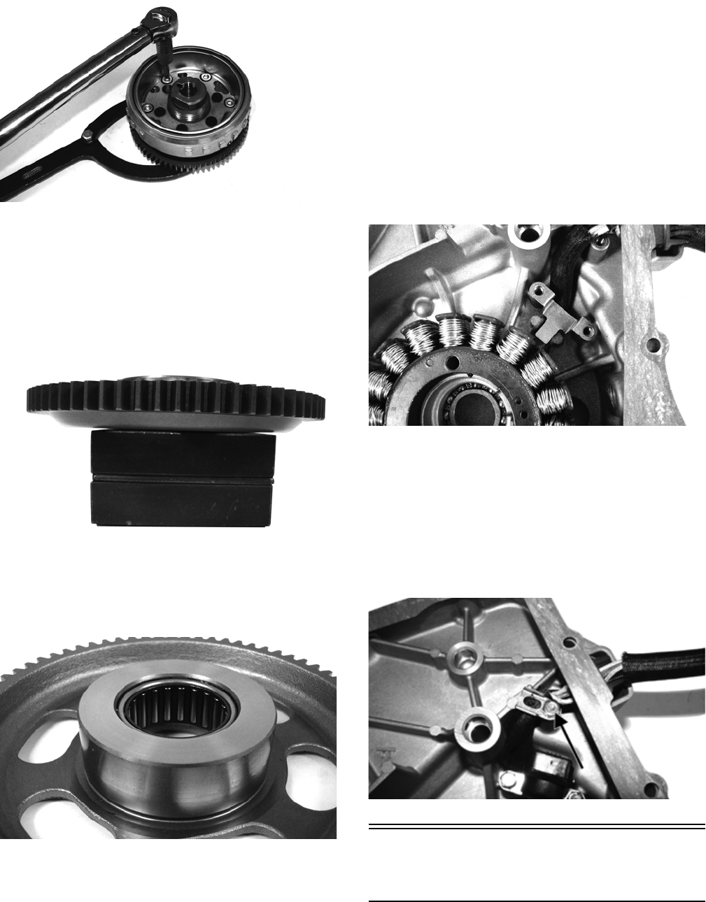
65
FI578
REPLACING STARTER GEAR
BEARING
1. Support the starter clutch gear in a press making sure
to support the hub around the entire circumference;
then using a suitable bearing driver, press the bearing
from the gear.
FI583
2. Thoroughly clean the gear hub; then apply a drop of
green Loctite #620 to the bearing outer race and
press into the gear hub until even with the lower
chamfer radius.
FI580
INSPECTING STATOR
COIL/MAGNETO COVER
ASSEMBLY
1. Inspect the stator coil for burned or discolored wir-
ing, broken or missing hold-down clips, or loose cap
screws.
2. Inspect the bearings in the magneto housing for dis-
coloration, roughness when rotated, and secure fit in
bearing bores.
REPLACING STATOR COIL/
CRANKSHAFT POSITION SENSOR
1. Remove the three cap screws securing the stator coil,
two cap screws securing the crankshaft position sen-
sor, and one cap screw from the harness hold-down.
2. Lift the rubber grommet out of the housing; then
remove the stator coil/crankshaft position sensor.
Account for and note the position of the harness
hold-down under the crankshaft position sensor.
FI590
3. Install the new stator coil assembly and secure with
three new “patch-lock” cap screws. Tighten to 15
ft-lb.
4. Place the stator wire harness hold-down into posi-
tion; then install the crankshaft position sensor and
secure with two cap screws. Tighten securely.
5. Install the upper cable hold-down and secure with a
cap screw. Tighten securely.
FI595A
Installing Right-Side
Components
NOTE: Plug the oil passage in the crankcase hous-
ing prior to installing the drive gear/driven gear
assembly to prevent loss of an alignment pin.
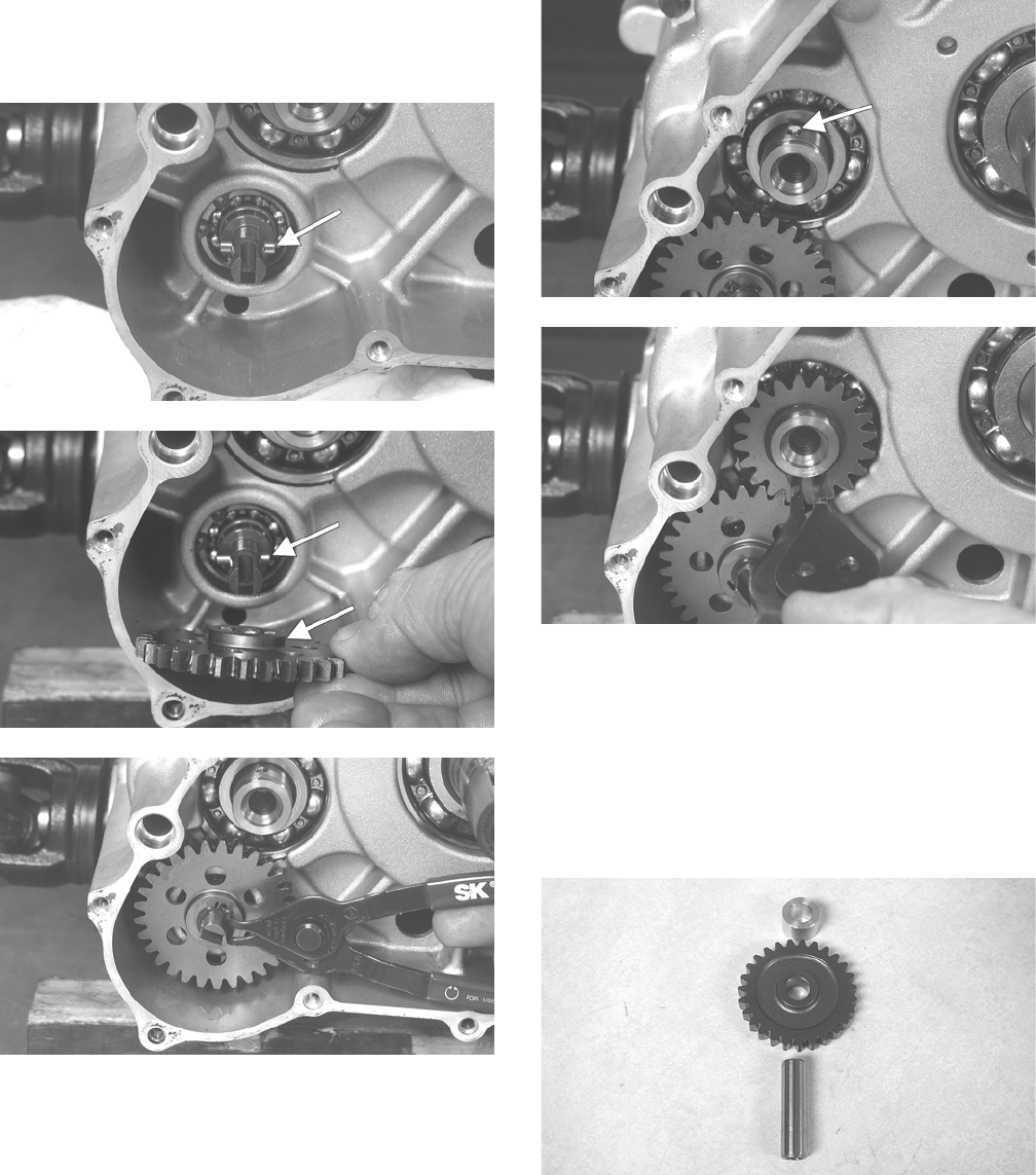
66
1. Install the water pump driven gear alignment pin and
the driven gear (with the beveled side of the gear fac-
ing outward as noted in removing); then secure with
the snap ring.
CD950A
CD952A
CD949
NOTE: The sharp side of the snap ring should be
facing outward.
2. Install the water pump drive gear drive pin and the
drive gear (with the flat side of the gear facing out-
ward as noted in removing); then secure with the
snap ring.
CD946A
CD944
NOTE: The sharp side of the snap ring should be
facing outward.
NOTE: Once the gears are secured, remove the oil
passage plug from the crankcase.
3. Install the two starter gear shafts; then install the two
starter gears (with the beveled side of the intermedi-
ate gear facing inward as noted in removing).
CD139
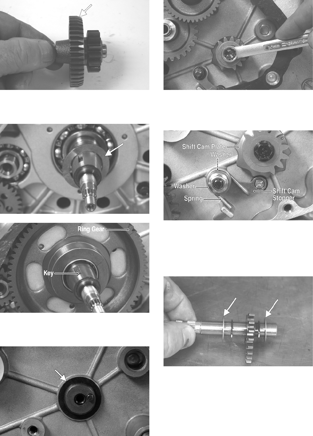
67
PR447A
4. In order on the crankshaft, install a washer, ring gear,
key, and the magneto rotor. Secure with the nut.
Tighten to 107 ft-lb.
CD948A
CD940B
5. Install the thrust washer and shift cam plate onto the
shift cam shaft; then coat the cap screw threads with
red Loctite #271 and tighten to 8 ft-lb.
PR433A
CD934
6. Install the shift cam stopper, spring, and two washers
(thick washer closest to the nut); then coat the threads on
the mounting stud with red Loctite #271 and install the
nut. Tighten to 8 ft-lb.
PR434A
NOTE: Rotate the shift cam plate to ensure it ratch-
ets with no binding.
7. Install the shift shaft with two washers making sure
to align the timing mark on the shift shaft with the
mark on the shift cam plate.
CD954A
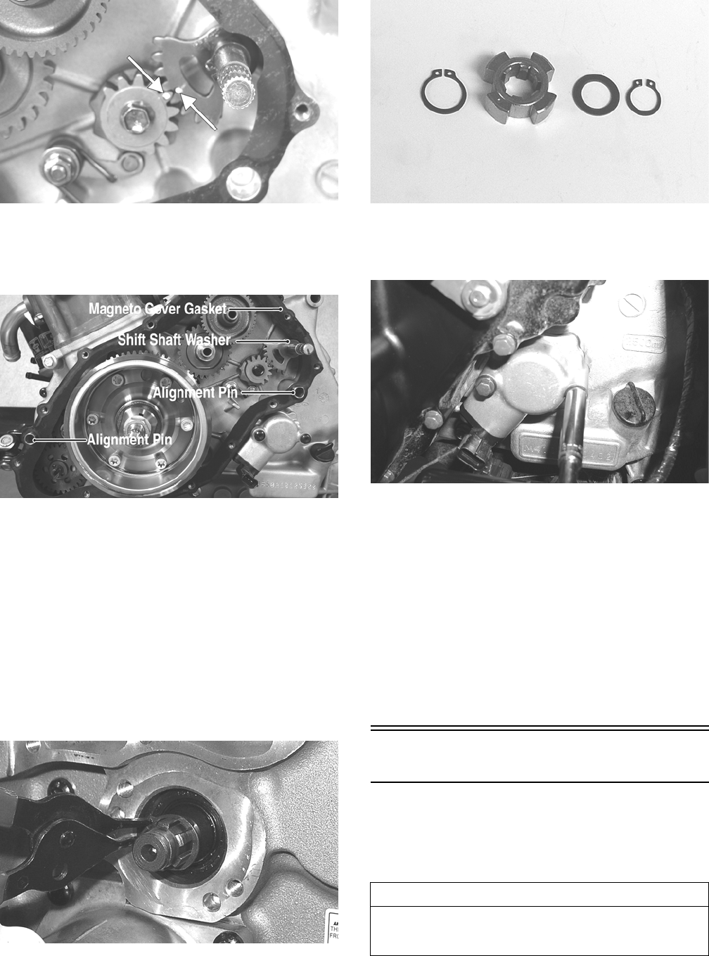
68
CD927A
8. Lubricate the magneto cover gasket with fresh
engine oil; then place it into position on the two
alignment pins. Make sure the outer shift shaft
washer is in place.
PR431A
9. Install the magneto cover and secure with the cap
screws. Tighten only until snug.
10. Place the bushing into position on the crankshaft
making sure a new, lubricated O-ring is inside the
bushing. Tighten the flange nut to 25 ft-lb.
11. Using a crisscross pattern, tighten the cap screws
(from step 9) to 8 ft-lb.
12. Clean the countershaft and trigger splines thoroughly
and install the inner snap ring onto the shaft; then
apply green Loctite #620 to the trigger and counter-
shaft splines and install the trigger. Secure with a flat
washer and outer snap ring.
GZ253
GZ254
13. Using a new gasket, install the speed sensor housing
onto the crankcase and secure with two cap screws.
Tighten to 8 ft-lb.
CD069
14. Place the water pump into position and secure with
two cap screws. Tighten to 8 ft-lb.
NOTE: Ensure the slotted water pump shaft is
aligned with the groove in the counter balancer shaft.
15. Install the crossover tube on the water pump and cylinder
head making sure the O-ring is properly positioned.
16. On the XT, install the shift arm on the shift arm shaft
making sure the scribed marks (from removing) are
aligned. Tighten securely.
17. Place the outer magneto cover into position on the
left-side cover; then tighten four cap screws to 6 ft-lb.
Left-Side Components
NOTE: For efficiency, it is preferable to remove and
disassemble only those components which need to be
addressed and to service only those components. The
technician should use discretion and sound judgment.
NOTE: The engine/transmission does not have to
be removed from the frame for this procedure.
AT THIS POINT
To service any one specific component, only limited dis-
assembly of components may be necessary. Note the
AT THIS POINT information in each sub-section.
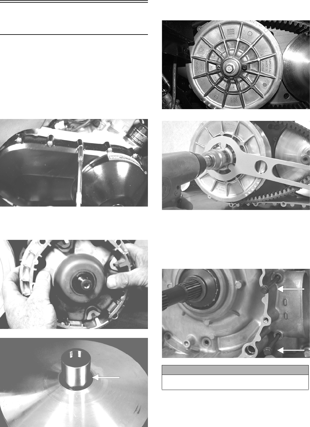
69
Removing Left-Side
Components
A. V-Belt Cover
B. Driven Pulley
C. Clutch Cover
D. Oil Pump
1. Remove the cap screws securing the V-belt cover
noting the location of the different-lengthed cap
screws for installing purposes; then using a rubber
mallet, gently tap on the cover tabs to loosen the
cover. Account for two alignment pins.
CD079
2. Remove the nut and washer securing the movable
drive face; then remove the face. Account for a
spacer.
CD963
CD966A
3. Remove the V-belt.
4. Remove the bolt (550) or nut (700) securing the
fixed driven assembly; then remove the assembly.
H1-019
PR388
5. Remove the fixed drive face.
6. Remove the cap screws securing the clutch cover.
Note the location of the different-lengthed cap
screws for installing purposes. Using a rubber mallet,
carefully remove the cover. Account for two align-
ment pins.
CD973A
CAUTION
Care must be taken when removing the cover so the
cover gasket is not damaged.
550
700
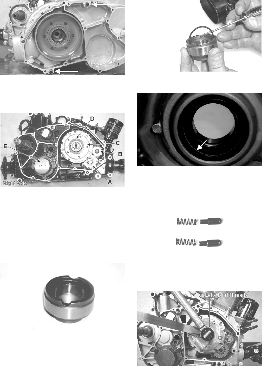
70
CD974A
NOTE: For steps 7-13, refer to illustration CC829B.
NOTE: To aid in installing, it is recommended that
the assemblies are kept together and IN ORDER.
CC829B
7. Remove the one-way clutch (D) from the clutch
housing. Note the location of the green alignment dot
(or the word OUTSIDE) for installing purposes.
8. Using a hydraulic press, remove the clutch housing
assembly from the clutch cover. Account for the left
fixed drive spacer and an O-ring inside the fixed
drive spacer.
CF085
CC596
NOTE: Account for and inspect the clutch housing seal.
CF088A
9. On the XT, remove the two cap screws securing the
gear position switch; then remove the switch.
Account for two contact pins with springs.
CD997
10. Remove the nut (left-hand threads) securing the
clutch shoe assembly (C).
PR410A
KEY
A. Oil Pump Driven Gear
B. Oil Pump Drive Gear
C. Clutch Shoe Assembly
D. One-Way Clutch
E. Final Drive Carrier Bearing
Housing
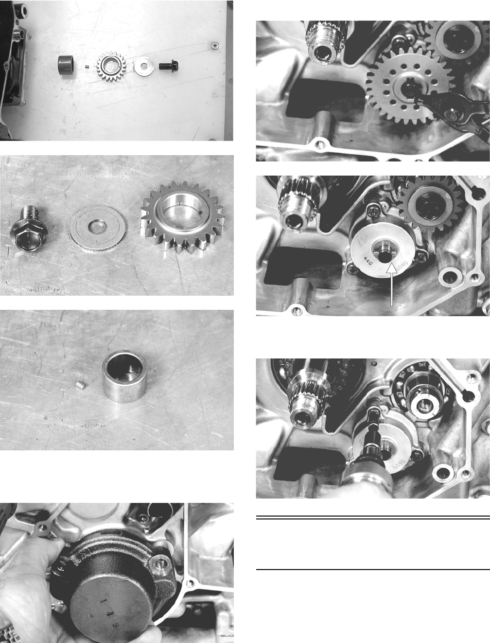
71
11. Remove the cap screw securing the oil pump drive gear
(B). Account for a cap screw, washer, pin, and spacer.
CC606
CD987
CD993
12. Using an impact wrench, remove the cap screws secur-
ing the final drive carrier bearing housing (E); then
remove the housing and account for two alignment pins.
CD999
13. Remove the snap ring securing the oil pump driven
gear (A); then remove the gear noting the direction
of the sides of the gear for installing purposes.
Account for a pin and a washer.
CD984
CD895A
14. Using an impact driver, remove the three torx-head
screws securing the oil pump; then remove the pump.
CD988
Servicing Left-Side
Components
INSPECTING CENTRIFUGAL
CLUTCH SHOE
1. Inspect the clutch shoes for uneven wear, chips, cracks,
or discoloration. If any shoe is damaged, replace the
complete set.
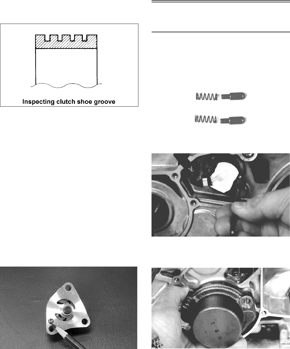
72
2. Inspect the clutch shoes for wear or damage. If any shoe
is worn to the bottom of the groove, replace the clutch
assembly.
ATV1014
INSPECTING CLUTCH HOUSING
1. Inspect the clutch housing for burns, grooving, cracks, or
uneven wear.
2. If the housing is damaged in any way, the housing must
be replaced.
INSPECTING PRIMARY ONE-WAY
DRIVE
1. Insert the drive into the clutch housing.
2. Rotate the inner race by hand and verify the inner race
rotates only one direction.
3. If the inner race is locked in place or rotates both direc-
tions, the drive assembly must be replaced.
INSPECTING OIL PUMP
1. Inspect the pump for damage.
2. It is inadvisable to remove the screw securing the pump
halves. If the oil pump is damaged, it must be replaced.
CC446D
DRIVEN PULLEY ASSEMBLY
NOTE: The driven pulley is a non-serviceable com-
ponent. If the pulley faces, cam ramps, or sheave
bushing are worn or loose, the pulley must be
replaced as an assembly. Do not disassemble the
driven pulley.
Installing Left-Side
Components
1. On the XT, install the gear position switch ensuring the
two pins and springs are properly positioned. Tighten the
cap screws securely.
CD997
CD994
2. Install the secondary shaft bearing housing making sure
the two alignment pins are properly positioned. Tighten
the new “patch-lock” cap screws to 28 ft-lb.
CD999
3. Install the oil pump onto the engine; then tighten the
screws (coated with red Loctite #271) to 8 ft-lb.
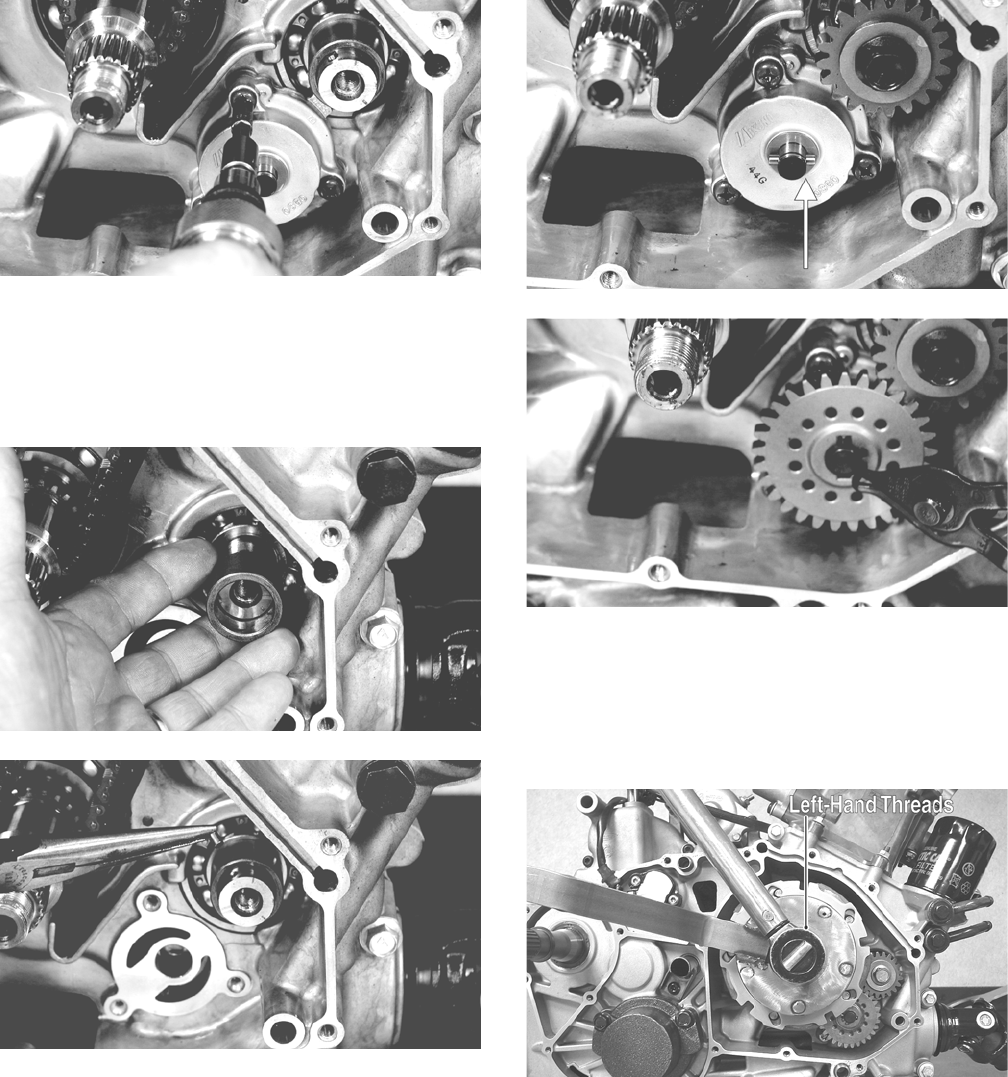
73
CD988
4. Install the oil pump drive gear spacer onto the crank bal-
ancer shaft. Grease the pin and insert it into the shaft;
then install the drive gear making sure the raised side of
the gear is facing toward the inside. Secure the gear with
the cap screw (threads coated with red Loctite #271) and
the washer. Tighten the cap screw to 63 ft-lb.
CD992
CD991
5. Grease the driven gear pin and insert the oil pump
into the case. Tighten the oil pump screws to 8 ft-lb.
Install the washer and pin; then install the driven
gear noting the direction on the sides of the gear
from removing). Secure with a snap ring.
CD985A
CD984
NOTE: When installed correctly, the sides of the
drive and driven gears will be flush with each other.
6. Install the clutch shoe assembly and secure with the
flange nut (threads coated with red Loctite #271).
Tighten to 221 ft-lb.
PR410A
7. Install the clutch cover alignment pins into the crank-
case, apply oil to the cover gasket, and install the
gasket onto the crankcase.
8. Install the one-way clutch onto the clutch shoe
assembly.
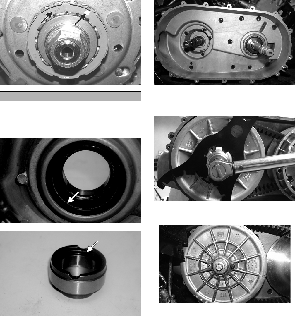
74
PR399A
9. Lightly grease the clutch housing seal; then insert the
left fixed-drive spacer.
CF088A
CF085A
10. Apply grease to the outer edges of the clutch hous-
ing; then from inside the clutch cover, install the
clutch housing into the cover using a rubber mallet.
11. Place the clutch cover/housing assembly into posi-
tion on the crankcase; then secure with the cap
screws making sure the different-lengthed cap
screws are in their proper location. Tighten to 8 ft-lb.
H1-023
12. Place the driven pulley assembly into position and
secure with the bolt (550) or nut (700). Tighten to 80
ft-lb (550) or 162 ft-lb (700).
CF262
13. Tighten the cap screw with washer to 60 ft-lb.
H1-019
14. Slide the fixed drive face onto the clutch shaft.
15. Spread the faces of the driven pulley by threading a cap
screw into one of the bosses of the driven fixed face;
then tighten the cap screw until the V-belt drops into the
driven pulley 1/2 to 3/4 inch.
CAUTION
When installed correctly, the green alignment dot (or the
word OUTSIDE) on the one-way clutch is visible.
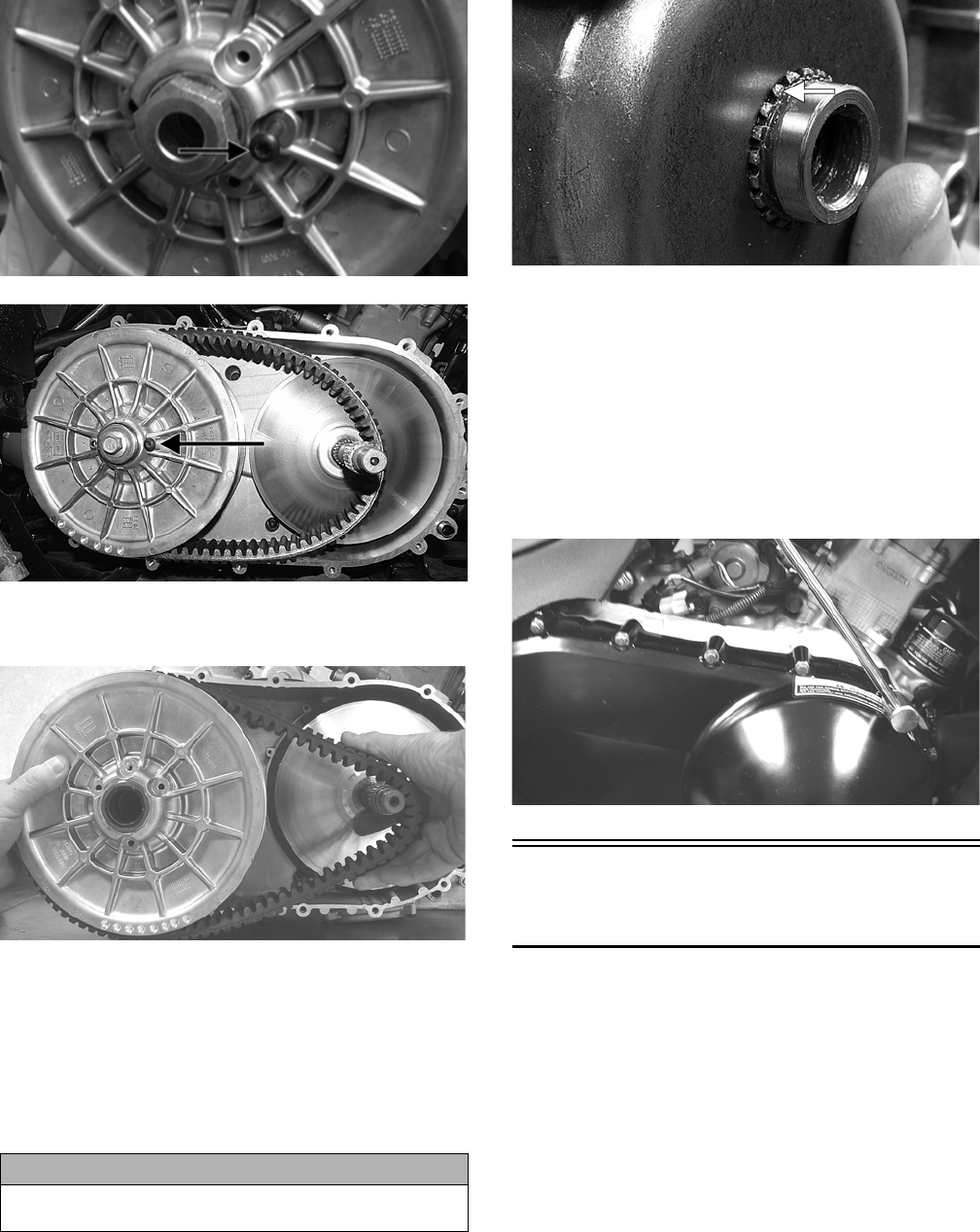
75
CF270A
H1-020A
16. Place the V-belt into position on the driven pulley and
over the front shaft.
PR389
NOTE: The arrows on the V-belt should point in the
direction of rotation.
17. Pinch the V-belt together near its center and slide the
spacer and movable drive face onto the driveshaft.
Using an appropriate spanner wrench, secure the
drive face with a nut and (threads coated with red
Loctite #271). Tighten the nut to 165 ft-lb.
FI428A
NOTE: At this point, the cap screw can be removed
from between the driven pulley faces.
18. With the vehicle in neutral, rotate the V-belt and clutches
counterclockwise until the V-belt is flush with the top of
the driven pulley.
19. Place the V-belt cover gasket into position; then install
the cover and secure with the cap screws making sure the
different-lengthed cap screws are in their proper loca-
tion. Tighten the cap screws to 8 ft-lb.
CD083
Center Crankcase
Components
NOTE: This procedure cannot be done with the
engine/transmission in the frame. Complete Removing
procedures for Top-Side, Left-Side, and Right-Side must
precede this procedure.
NOTE: For efficiency, it is preferable to remove and dis-
assemble only those components which need to be
addressed and to service only those components. The
technician should use discretion and sound judgment.
CAUTION
Make sure the splines extend beyond the drive face or a
false torque reading and spline damage may occur.
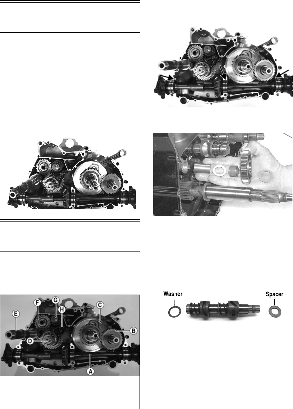
76
Separating Crankcase
Halves
1. Remove the left-side cap screws securing the crank-
case halves. Note the location of the differ-
ent-lengthed cap screws.
2. Remove the right-side cap screws securing the
crankcase halves. Note the location of the differ-
ent-lengthed cap screws.
3. Using the Crankcase Separator/Crankshaft Remover
and tapping lightly with a rubber mallet, separate the
crankcase halves. Account for two alignment pins.
NOTE: To keep the shaft/gear assemblies intact for
identification, tap the shafts toward the right-side
crankcase half when separating the halves.
PR786
Disassembling Crankcase
Half
NOTE: For steps 1-7, refer to illustration PR787A.
NOTE: To aid in installing, it is recommended that
the assemblies are kept together and IN ORDER.
PR787A
1. Remove the secondary driven shaft assembly (A)
noting the location of the bearing locating pins.
Account for the bearing C-ring.
PR787B
2. Remove the reverse idler gear assembly (F). Account
for all washers, shaft, bushing, and the gear.
CC668
3. Remove the shift shaft (H); then remove the two
forks taking note of the direction of the tabs on the
forks for assembling purposes.
4. Remove the gear shift shaft (G) noting the location
of the two holes on the end of the shaft. Account for
a spacer and a washer.
DE677A
5. Remove the countershaft assembly (D). Account for
a washer on each end of the countershaft.
KEY
A. Secondary Driven Shaft
Assembly
B. Crank Balancer Assembly
C. Crankshaft
D. Countershaft Assembly
E. Driveshaft
F. Reverse Idler Gear Assembly
G. Gear Shift Shaft
H. Shift Shaft with 2 Forks
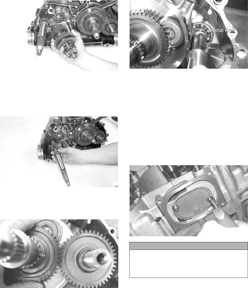
77
CC674
NOTE: Do not disassemble the countershaft assem-
bly unless necessary. If necessary, see Servicing
Center Crankcase Components sub-section.
6. Using a rubber mallet, tap on the crankcase to
remove the driveshaft.
CC675
7. Note the timing marks on the crank balancer assem-
bly (B) gear and crankshaft (C) gear for assembling
purposes; then slide the crank balancer gear off the
crank balancer. Account for the key in the keyway.
CD826
8. Remove the crank balancer.
NOTE: There is a flat spot on the crank balancer bear-
ing flange to allow clearance past the crankshaft.
CD832B
9. Remove the snap ring securing the water pump driven
gear shaft.
10. Using a hydraulic press, remove the crankshaft assem-
bly.
NOTE: Use a protective end cap to prevent damage to
the crankshaft threads.
11. Remove the cap screws securing the oil strainer cap; then
remove the cap.
12. Remove the two cap screws securing the oil strainer;
then remove the strainer.
NOTE: Thoroughly clean any sealant from the oil
strainer cap.
PR406
13. To remove the secondary drive/bevel gear, remove the
secondary drive bearing housing; then remove the nut
securing the drive/bevel gear shaft in the bearing and
using a plastic mallet, drive the shaft out of the bearing.
Account for shim/shims.
NOTE: Shims should be measured and kept for a start-
ing point in adjusting backlash.
CAUTION
Unless the secondary drive gear, bevel gear, or bear-
ings require service, do not remove the secondary drive
assembly from the case. If removed, bevel gear back-
lash will have to be adjusted requiring re-shimming of
the drive bevel gear shaft.
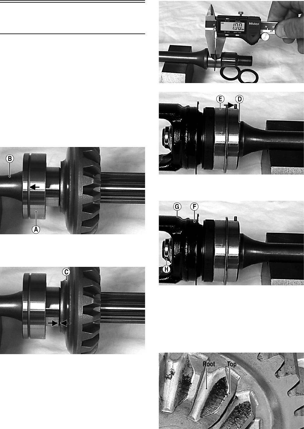
78
Servicing Center
Crankcase Components
SECONDARY OUTPUT DRIVE
GEARS
Initial Set-Up
NOTE: If the secondary output driven shaft is replaced
or disassembled, the initial set-up must be performed to
establish correct gear tooth contact. If only the second-
ary output drive shaft or secondary output driven gear is
replaced, proceed to Correcting Backlash in this
sub-section.
1. Install a new bearing (A) onto the secondary driven shaft
(B) making sure the bearing locating groove is directed
away from the driven gear splines.
MT011A
2. Using a suitable press, install the driven gear (C) on the
shaft until the gear firmly seats on the shoulder of the
shaft.
MT011B
3. If installing the existing shaft, start with the shims
removed during disassembly or if installing a new shaft,
start with approximately 1.0 mm shims at point (D); then
install the output drive shaft bearing (E) making sure the
locating pin is directed toward the center of the shaft.
MT012
MT008A
4. Install a new seal (F), output yoke (G), and nut (H)
and tighten to 74 ft-lb.
MT008B
NOTE: Do not use a new lock nut at this time as this
procedure may have to be repeated.
5. Place the assembled shaft into the left crankshaft case;
then lightly coat the gear teeth with machinist’s lay-out
dye. Rotate the shafts through several rotations in both
directions. Gear contact should extend from the root to
the top of the gear teeth.
MT016A
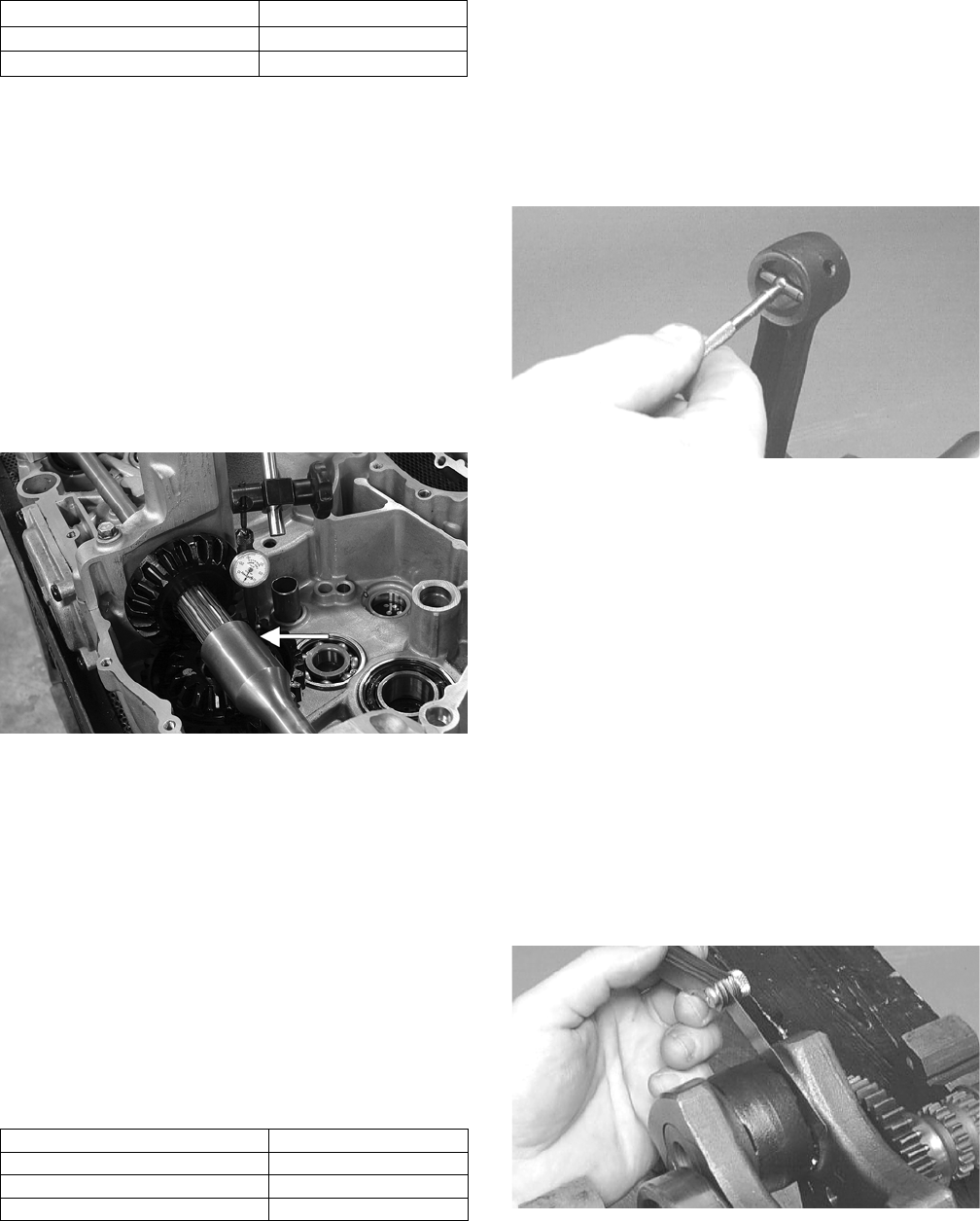
79
6. To adjust tooth contact, use the following chart to
correctly shim the driven shaft.
7. After correct tooth contact is established, proceed to
Checking Backlash in this sub-section.
Checking Backlash
1. If removed, install the secondary drive/bevel gear
shaft into the crankcase; then tighten the nut to 59
ft-lb.
2. Install the secondary drive bearing support; then
install the secondary driven output shaft into the
crankcase.
3. Mount the dial indicator so the tip is contacting a
tooth on the secondary drive bevel gear.
4. While rocking the drive bevel gear back and forth,
note the maximum backlash reading on the gauge.
MT005A
5. Acceptable backlash range is 0.127-0.381 mm
(0.005-0.015 in.).
Correcting Backlash
NOTE: If backlash measurement is within the
acceptable range, no correction is necessary.
1. If backlash measurement is less than specified,
remove an existing shim, measure it, and install a
new thinner shim.
2. If backlash measurement is more than specified, remove
an existing shim, measure it, and install a thicker shim.
NOTE: Continue to remove, measure, and install
until backlash measurement is within tolerance. Note
the following chart.
After backlash and tooth contact are within specifica-
tions, apply red Loctite #271 to the driveshaft threads and
driven output shaft threads; then using new nuts, tighten
the output shaft nut to 59 ft-lb and the output yoke nut to
74 ft-lb.
CRANKSHAFT ASSEMBLY
NOTE: The crankshaft and connecting rod is a
non-serviceable assembly. If any component is out of
specification, the assembly must be replaced.
Measuring Connecting Rod
(Small End Inside Diameter)
1. Insert a snap gauge into the upper connecting rod small
end bore; then remove the gauge and measure it with
micrometer.
CC290D
2. Maximum diameter must not exceed specifications.
Measuring Connecting Rod
(Small End Deflection)
1. Place the crankshaft on a set of V blocks and mount a
dial indicator and base on the surface plate. Position
the indicator contact point against the center of the
connecting rod small end journal.
2. Zero the indicator and push the small end of the con-
necting rod away from the dial indicator.
3. Maximum deflection must not exceed specifications.
Measuring Connecting Rod
(Big End Side-to-Side)
1. Push the lower end of the connecting rod to one side of
the crankshaft journal.
2. Using a feeler gauge, measure the gap between the con-
necting rod and crankshaft journal.
CC289D
3. Acceptable gap range must not exceed specifications.
Measuring Crankshaft (Runout)
1. Place the crankshaft on a set of V blocks.
Tooth Contact Shim Correction
Contact at Top Increase Shim Thickness
Contact at Root Decrease Shim Thickness
Backlash Measurement Shim Correction
Under 0.127 mm (0.005 in.) Decrease Shim Thickness
At 0.127-0.381 mm (0.005-0.015 in.) No Correction Required
Over 0.381 mm (0.015 in.) Increase Shim Thickness
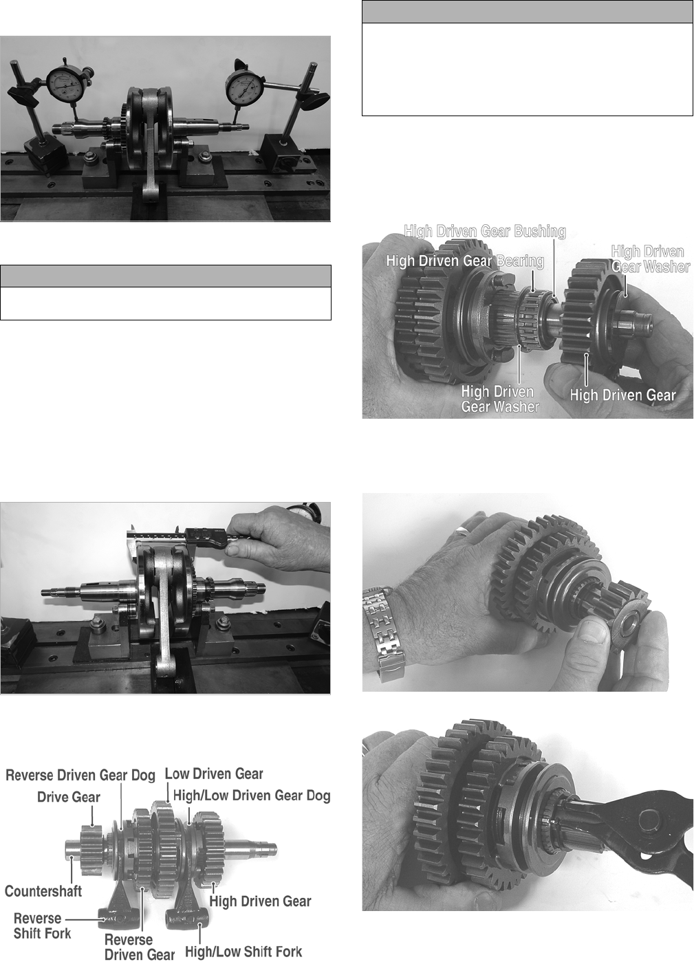
80
2. Mount a dial indicator and base on the surface plate.
Position the indicator contact at point 1 of the crankshaft.
H1-003
3. Zero the indicator and rotate the crankshaft slowly.
4. Maximum runout must not exceed specifications.
NOTE: Proceed to check runout on the other end of the
crankshaft by positioning the indicator contact at point 2
and following steps 3-4.
Measuring Crankshaft
(Web-to-Web)
1. Using a calipers, measure the distance from the outside
edge of one web to the outside edge of the other web.
H1-005
2. Acceptable width range must not exceed specifications.
COUNTERSHAFT
GZ281A
Disassembling
1. Remove the shift forks noting the positions for assem-
bling; then remove the high driven gear outer washer,
high driven gear, high driven gear bearing, high driven
gear bushing, and high driven gear inner washer.
GZ283A
2. Remove the drive gear; then remove the snap ring secur-
ing the reverse driven gear dog and bushing to the coun-
tershaft.
GZ296
GZ312
3. Remove the reverse driven gear dog.
CAUTION
Care should be taken to support the connecting rod
when rotating the crankshaft.
CAUTION
When disassembling the countershaft, care must be
taken to note the direction each major component (dog,
gear) faces. If a major component is installed facing the
wrong direction, transmission damage may occur
and/or the transmission will malfunction. In either case,
complete disassembly and assembly will be required.
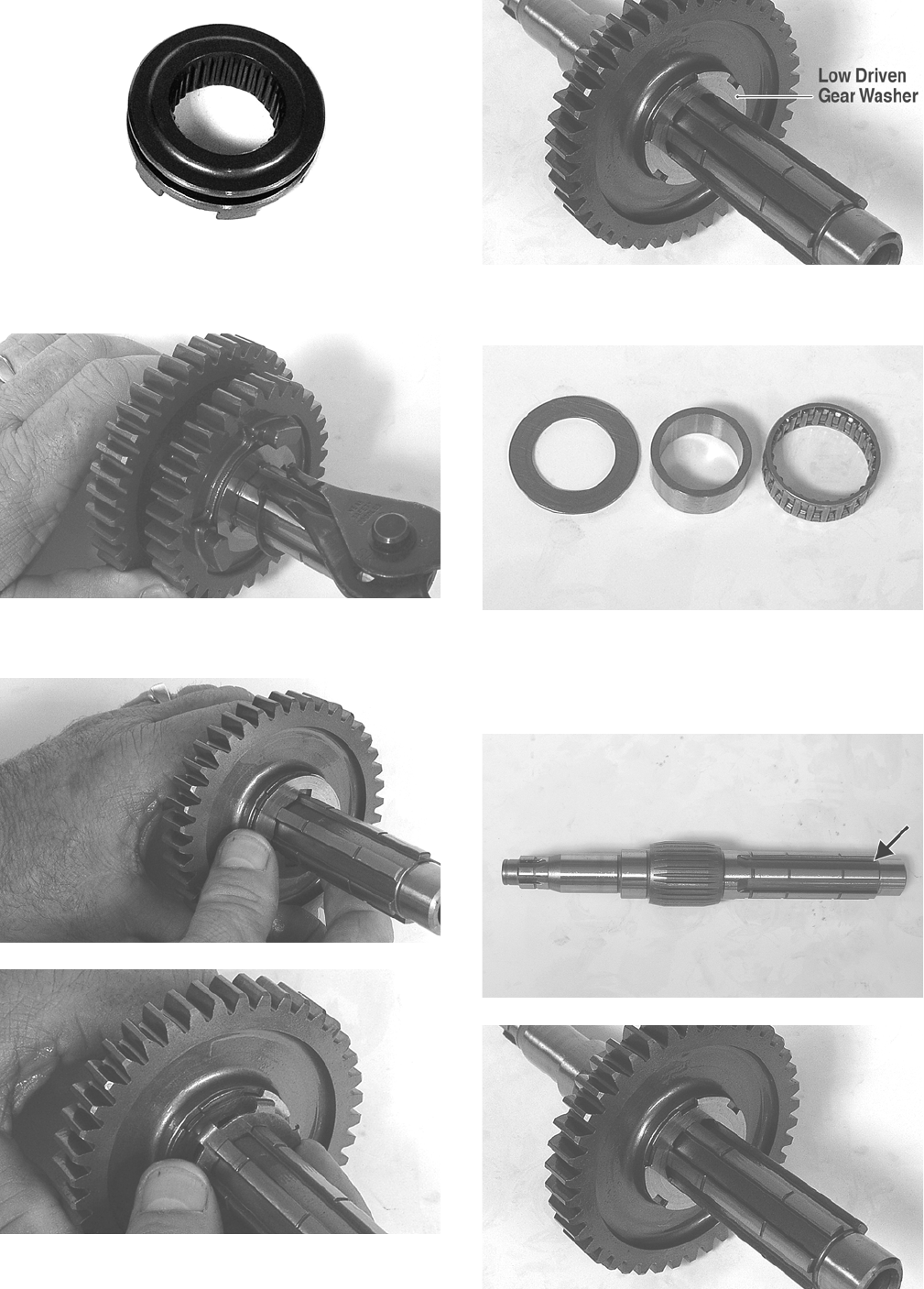
81
GZ313A
4. Remove the snap ring securing the reverse driven
gear and washer; then remove the washer and gear.
GZ314
5. Remove the reverse driven washer; then remove the
low driven gear locking washer.
GZ320
GZ319
GZ318A
6. Remove the low driven gear. Account for a bearing,
bushing, and thrust washer.
GZ316
Assembling
1. From the drive gear end, install a thrust washer, bushing,
and bearing; then install the low driven gear and washer.
GZ317A
GZ318
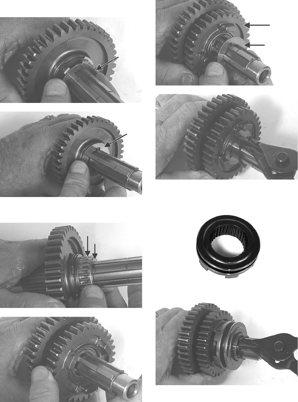
82
2. Install the low driven gear locking washer; then
install the inner reverse driven gear washer.
GZ319B
GZ320B
3. Install the reverse driven bushing and bearing; then
install the reverse driven gear.
GZ286A
GZ287
4. Install the outer reverse driven washer; then secure
the reverse driven gear assembly with a snap ring.
GZ288A
GZ314
5. Install the reverse driven gear dog onto the counter-
shaft and secure with a snap ring.
GZ313A
GZ312
6. From the opposite end of the countershaft, install the
high/low driven gear dog (A), thrust washer (B), bushing
(C), bearing (D), high/low driven gear (E), and spacer
washer (F).
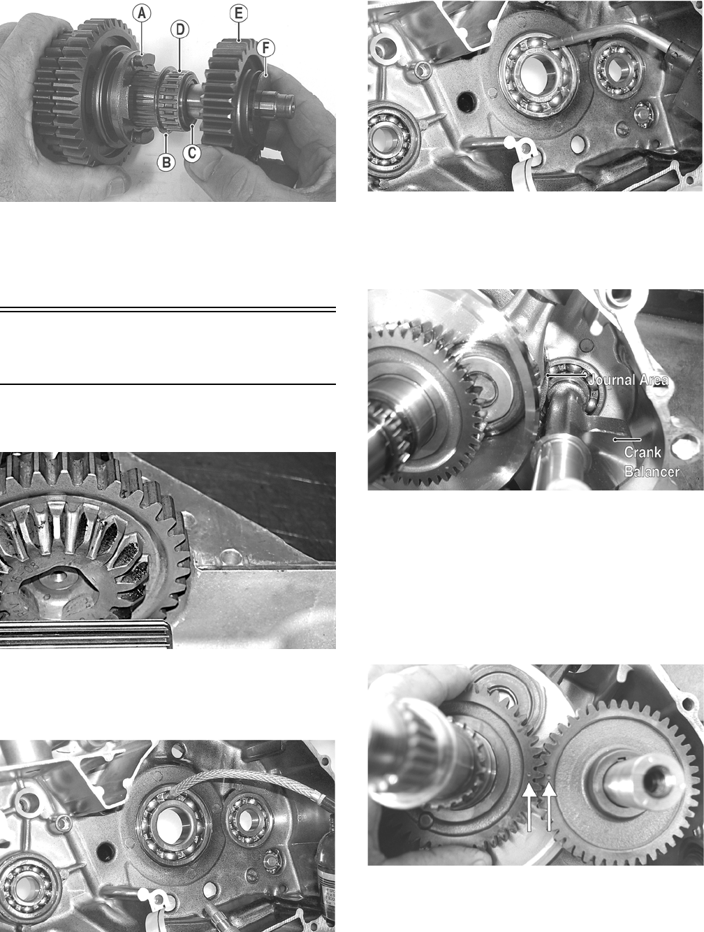
83
GZ283B
7. Install the two drive gear washers and the shift forks. The
countershaft is now ready for installation.
NOTE: When installing the countershaft assembly,
account for the washer on each end of the shaft.
Assembling Crankcase
Half
1. Install the secondary drive gear assembly into the crank-
case.
MT014
2. Apply a liberal amount of engine oil to the crankshaft
bearing. Using a propane torch, heat the bearing until the
oil begins to smoke; then slide the crankshaft assembly
into place.
CC688
CC689
NOTE: If heating the bearing is not possible, the crank-
shaft can be installed using a crankshaft installing tool.
3. Install the crank balancer.
CD832B
NOTE: It will be necessary to rotate the crank balancer
until the counterweight is facing away from the crank-
shaft; then rotate the crankshaft clockwise into the jour-
nal area to allow the crank balancer to be fully seated.
4. Place the key into the crank balancer keyway; then
install the crank balancer gear making sure the alignment
dots on the crank balancer gear and the crankshaft gear
align.
CD826A
5. Install the driveshaft.
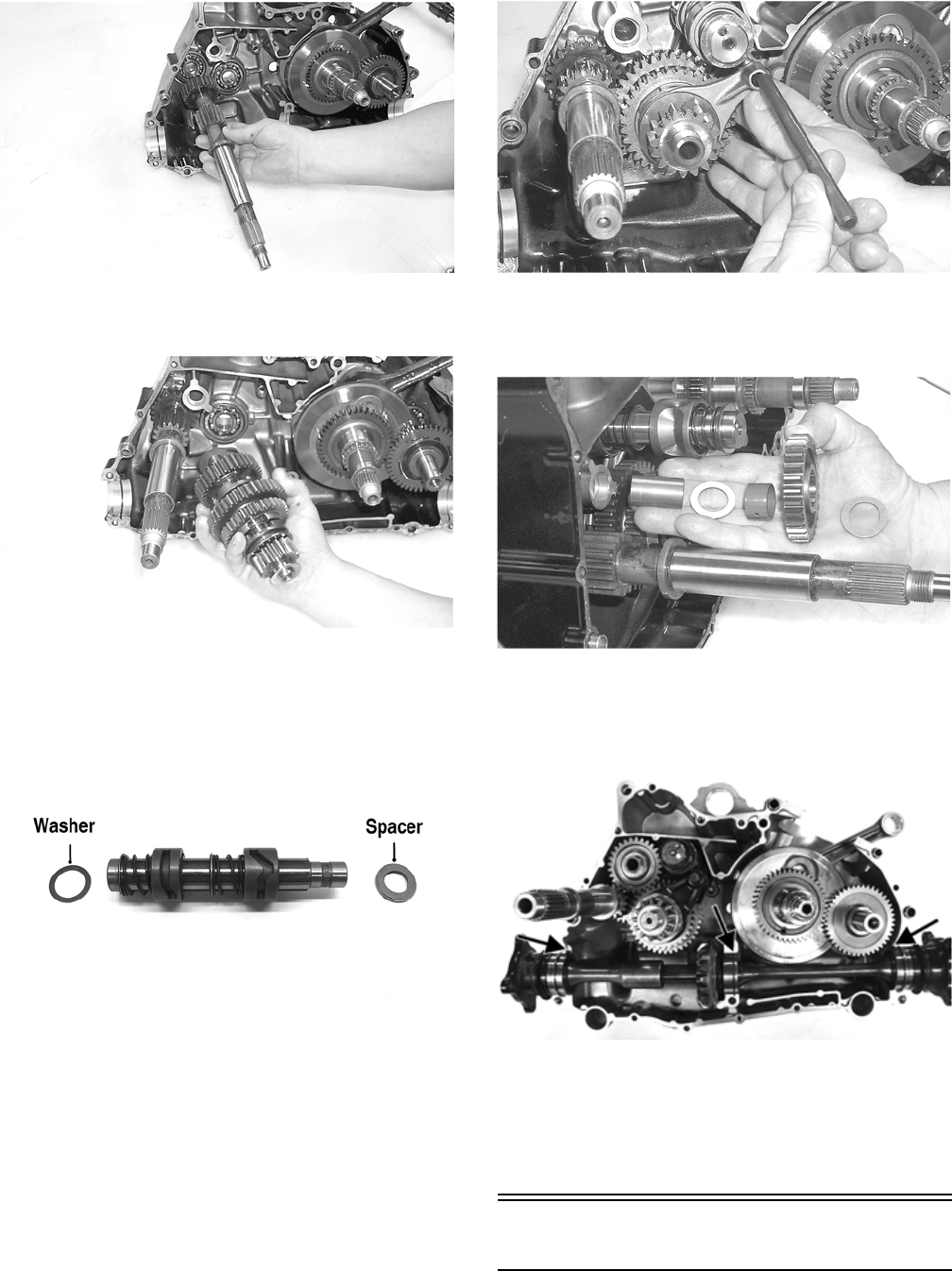
84
CC675
6. Place a washer on each end of the countershaft
assembly; then install the assembly.
CC674
7. Place a washer on the end of the gear shift shaft; then
install the shaft assembly making sure the two holes on
the end of the shaft are positioned vertically. Install the
spacer on the shift shaft.
DE677A
8. Insert the two shift forks into the sliding dogs noting the
direction of the tabs from disassembling; then install the
shift fork shaft.
NOTE: Make sure the shift fork tabs face upward
and that they are properly seated into the shift cams.
CC669
9. Install the reverse idler gear assembly noting the
positioning of the two washers, gear, bushing, and
shaft.
CC668
10. Install the front and rear secondary driven shaft assem-
blies into the left side of the crankcase making sure the
bearing locating pins are toward the top of the crankcase
and the bearing C-ring is fully seated in the crankcase.
PR787B
11. Place the oil strainer into position; then secure with the
two screws.
12. Place the oil strainer cap into position making sure sili-
cone sealant is applied; then secure the cap with cap
screws. Tighten to 10 ft-lb.
Joining Crankcase Halves
1. Apply High-Temp Sealant to the right-side mating sur-
face smoothing out any build-up or bumps.
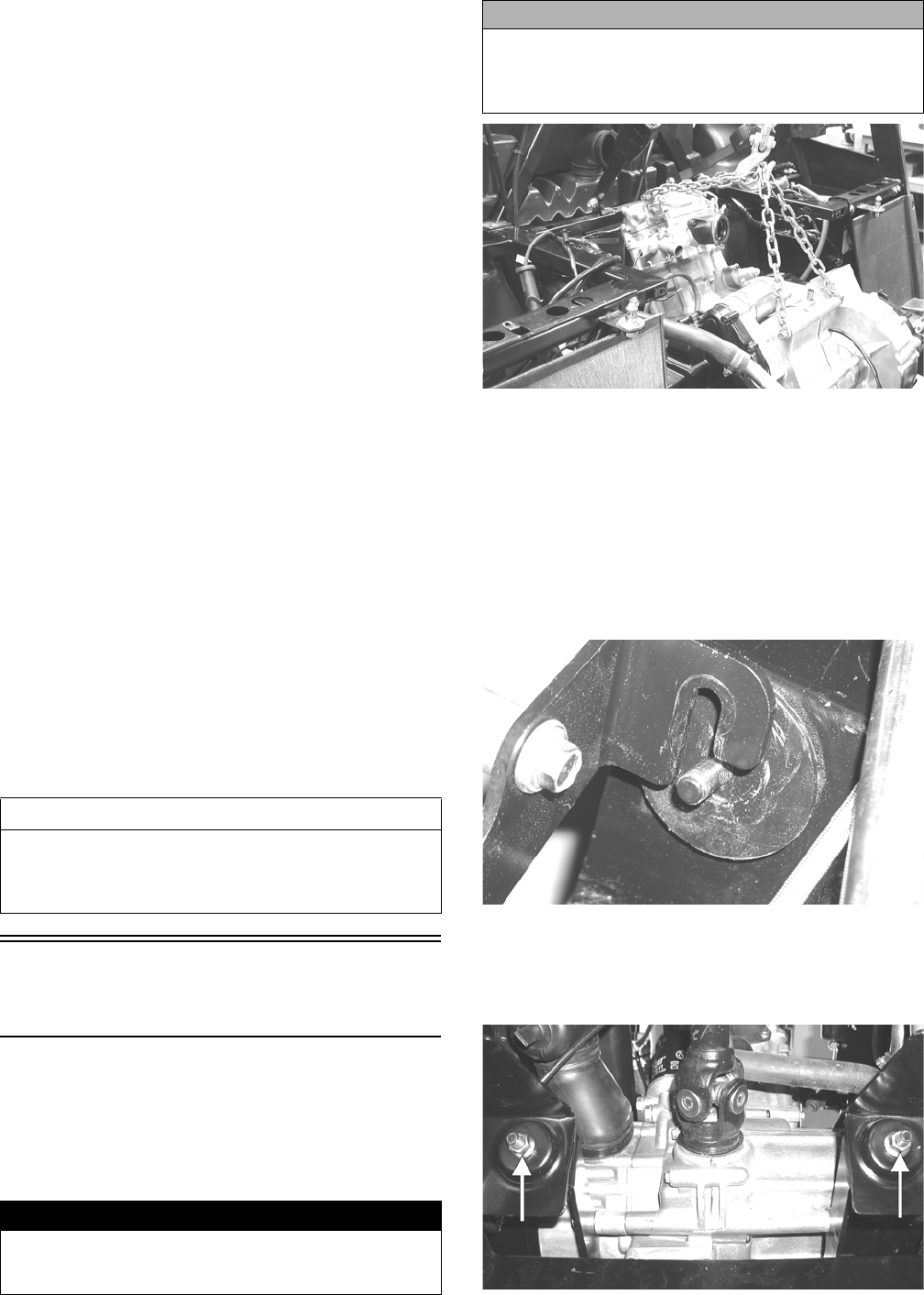
85
2. Lightly oil all bearings and grease all shafts in the
left-side crankcase.
3. Using a plastic mallet, lightly tap the case halves
together until cap screws can be installed.
4. From the left side, install the 8 mm cap screws; then
tighten only until snug.
NOTE: Rotate the shafts back and forth to ensure no
binding or sticking occurs.
5. From the right side, install the remaining 8 mm cap
screws (two inside the case); then tighten only until snug.
NOTE: Rotate the shafts back and forth to ensure no
binding or sticking occurs.
6. From the right side, install the case half 6 mm cap
screws; then tighten only until snug.
NOTE: Rotate the shafts back and forth to ensure no
binding or sticking occurs.
7. From the left side, install the 6 mm cap screws; then
tighten only until snug.
NOTE: Rotate the shafts back and forth to ensure no
binding or sticking occurs.
8. In a crisscross/case-to-case pattern, tighten the 8 mm cap
screws (from steps 4-5) until the halves are correctly
joined; then tighten to 20 ft-lb.
NOTE: Rotate the shafts back and forth to ensure no
binding or sticking occurs.
9. In a crisscross/case-to-case pattern, tighten the 6 mm cap
screws (from steps 6-7) to 8 ft-lb.
NOTE: Rotate the shafts back and forth to ensure no
binding or sticking occurs.
Installing
Engine/Transmission
NOTE: Arctic Cat recommends new gaskets and
O-rings be installed whenever servicing the vehicle.
1. Attach suitable lifting chains to the engine/transmission;
then using an engine hoist, lower the assembly into the
engine compartment.
PR114
NOTE: The rear engine mounting bracket and rear
engine mounts should be attached to the engine. The
front engine mounting bracket should be attached to the
engine, and the front engine mounts should be in the
frame.
2. Align the rear engine mount studs with the holes in the
frame and slowly lower into place. The front engine
mounting bracket will then slip over the engine mount
studs.
PR146
3. Install the flange nuts on the rear engine mount studs;
then secure the front engine mounting bracket to the
front engine mount studs with two flange nuts. Tighten
the four flange nuts to 45 ft-lb.
PR153A
AT THIS POINT
After completing center crankcase components, pro-
ceed to Installing Left-Side Components, to Installing
Right-Side Components, and to Installing Top-Side
Components.
! WARNING
Keep hands and fingers clear when lowering the
engine/transmission into place. The chains could shift
causing severe injury.
CAUTION
Make sure that all wiring, hoses, and brake lines are
routed away from engine mounts and engine brackets.
Pinching or breaking of lines or shorting of wiring could
occur.
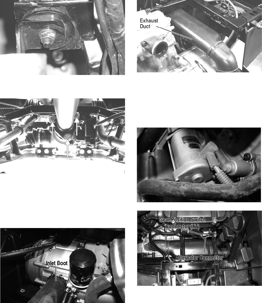
86
PR147
4. Install the cap screws securing the drive couplers to the
drive flanges and tighten to 40 ft-lb.
PR120A
5. Set the exhaust pipe in place; then install the muffler
and align the assembly to the engine. Install two cap
screws securing the exhaust pipe to the cylinder head
and tighten to 20 ft-lb.
6. Install the inlet boot on the V-belt housing; then
install the exhaust duct connecting the outlet housing
to the V-belt housing. Tighten all clamps securely.
HDX140A
PR144B
7. Connect the lower coolant hose to the water pump
housing; then connect the upper coolant hose to the
thermostat housing. Tighten the hose clamps
securely.
8. Install the starter wire on the starter and tighten the
nut securely; then connect the alternator connector
and gear position switch connector (XT).
PR838
PR266C
9. From the right-side, connect the speed sensor con-
nector, fuel level sensor connector, and temperature
sensor lead; then install the spark plug cap.
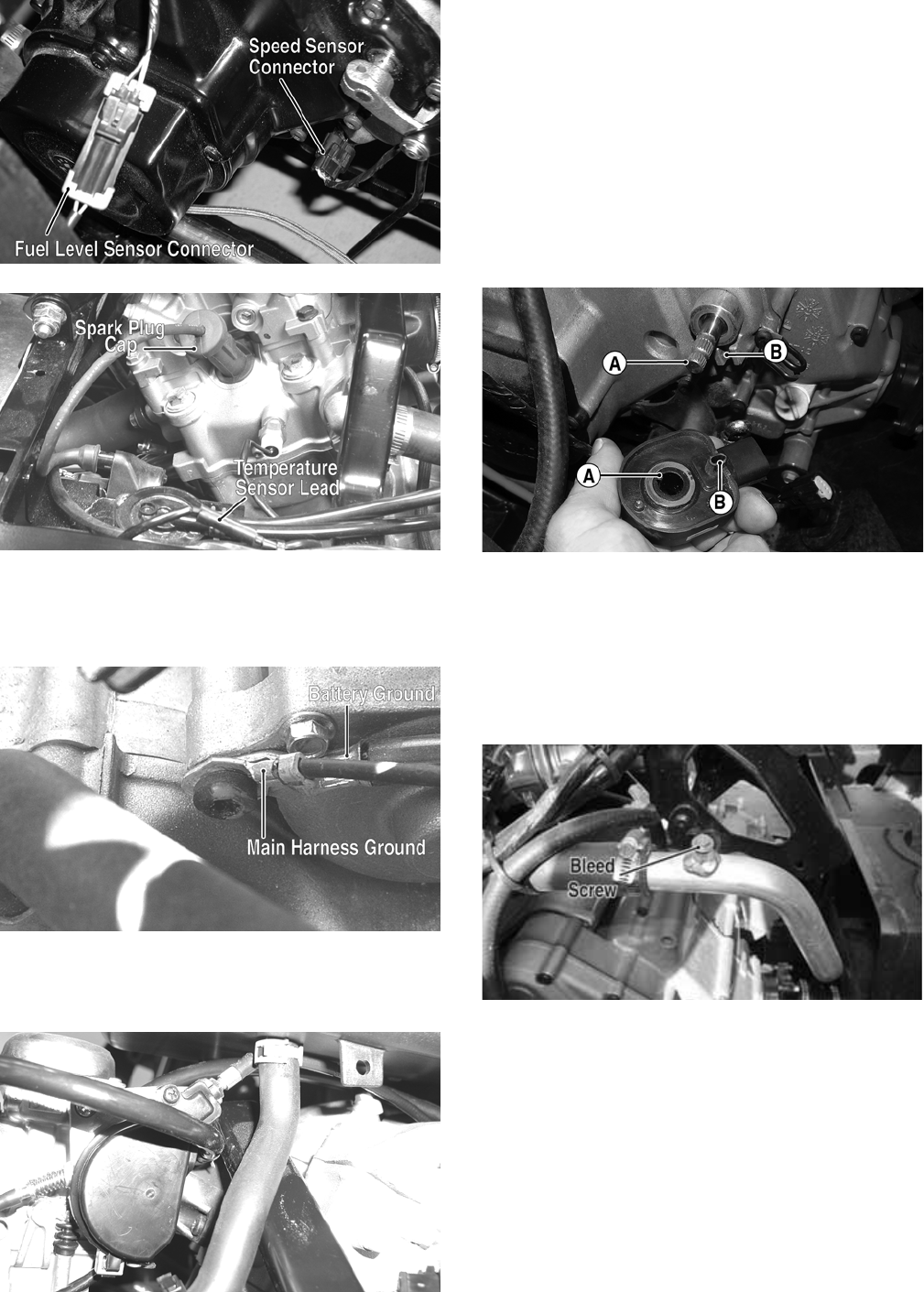
87
PR155B
PR130A
NOTE: Make sure the main harness ground and battery
ground wires are installed and secured in the proper loca-
tion with the unpainted cap screw.
PR474B
10. Install the throttle body and tighten the intake boot clamp
to 30 in.-lb; then connect the gasline hose, vacuum line,
and throttle cable.
PR154
11. Place the air filter assembly into position and secure with
the self-tapping screws; then connect the intake boot to
the throttle body and the inlet housing boot to the air fil-
ter housing. Tighten the clamps securely.
12. Place the shifter assembly into position and secure with
the four machine screws. Tighten securely.
13. On the XT, connect the shift cable to the shift arm; then
secure with the E-clip.
14. On the XTX, properly position the gear position switch on
the engine (A to A and B to B); then secure the shift cable
bracket to the engine case and tighten the engine case screws
to 8 ft-lb. Connect the gear position switch connector.
HDX252A
15. Fill the engine/transmission with the appropriate lubri-
cant.
16. Remove the coolant bleed screw from the upper coolant
pipe near the thermostat; then pour the correct mixture of
coolant into the radiator. When coolant with no air bub-
bles flows from the bleed hole, install the screw and
tighten securely; then complete filling the system.
PR819A
17. Connect the positive battery cable to the battery; then con-
nect the negative cable.
NOTE: Before operating vehicle, check and adjust shift
lever/cable as required (see Periodic Maintenance).
18. Install the left- and right-side seat bases; then install the
center console and seats. Make sure the seats lock
securely.
19. Start the engine and warm up to operating temperature.
Check for fluid leaks; then shut off engine and check oil
and coolant levels (see Periodic Maintenance -
Engine/Transmission Oil - Filter and Fuel/Lubrica-
tion/Cooling - Liquid Cooling System).
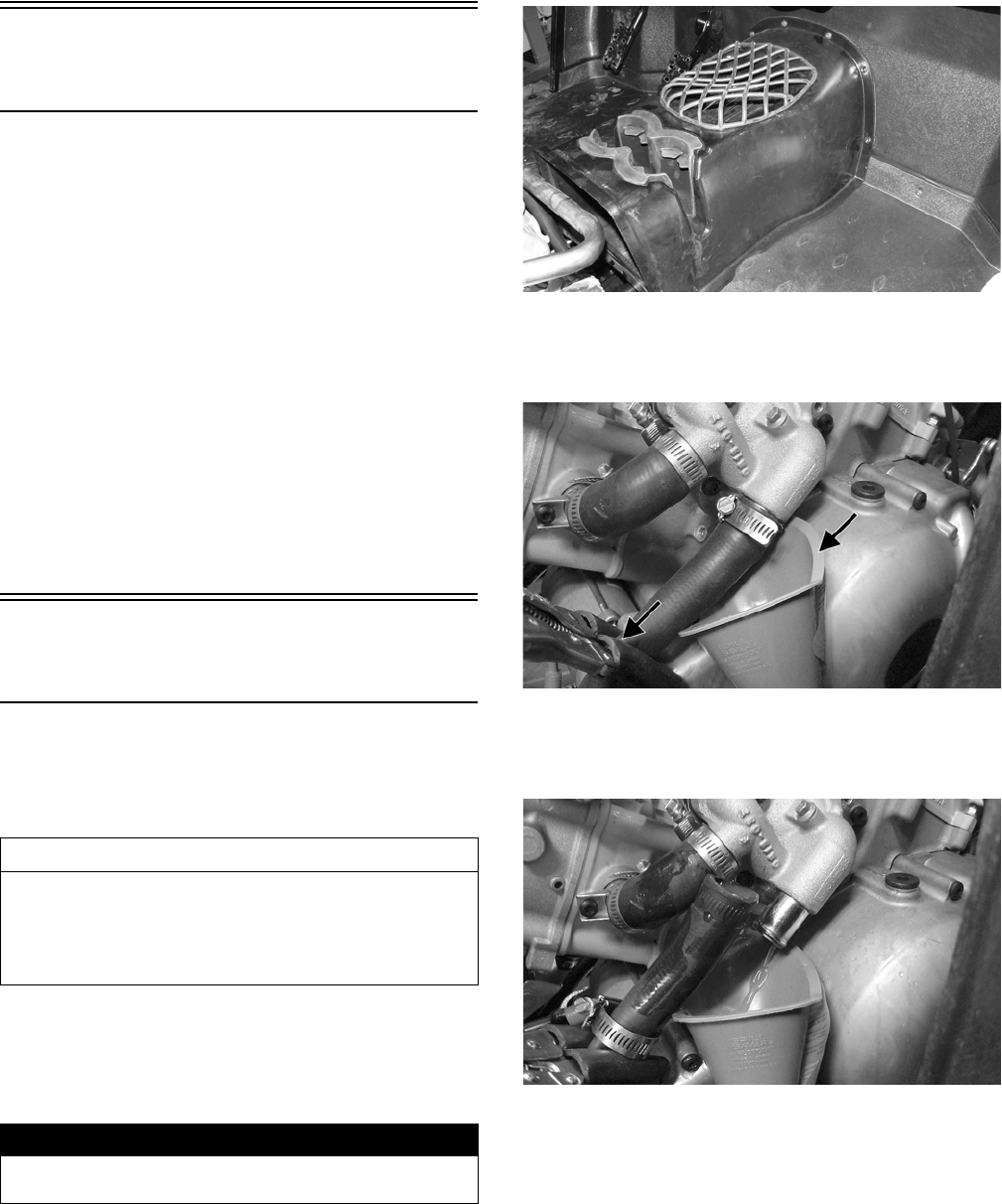
88
Prowler XTZ
(Table of Contents)
Removing Engine/Transmission...................................... 88
Top-Side Components .................................................... 94
Removing Top-Side Components ................................... 94
Servicing Top-Side Components..................................... 98
Installing Top-Side Components ................................... 104
Left-Side Components .................................................. 111
Removing Left-Side Components ................................. 111
Servicing Left-Side Components .................................. 113
Installing Left-Side Components ................................... 115
Right-Side Components................................................ 118
Removing Right-Side Components............................... 118
Servicing Right-Side Components ................................ 121
Installing Right-Side Components................................. 122
Center Crankcase Components.................................... 125
Separating Crankcase Halves....................................... 125
Disassembling Crankcase Half ..................................... 126
Servicing Center Crankcase Components.................... 127
Assembling Crankcase Half.......................................... 135
Joining Crankcase Halves............................................. 137
Installing Engine/Transmission...................................... 138
Removing
Engine/Transmission
Many service procedures can be performed without
removing the engine/transmission from the frame.
Closely observe the note introducing each sub-section for
this important information.
Support the vehicle on a suitable lift or jack stands allow-
ing room to perform work from the underside.
NOTE: Locate the jack stands to allow removing of
the center belly panel.
1. Remove the seats and center console; then remove
the left-side and right-side seat-bases.
2. Remove the storage console; then remove the floor
and drain the oil into a suitable container.
PR611
3. Clamp off the lower radiator hose near the water
pump; then place a suitable container and funnel
under the water pump.
PR587A
4. Loosen the hose clamp and remove the hose from the
water pump; then release the clamp from step 3 and
drain the coolant.
PR588
5. Remove the upper hose from the front cylinder head
allowing coolant to drain from the rear cylinder and
thermostat housing.
AT THIS POINT
If the technician’s objective is to service/replace
left-side cover oil seals, front output joint oil seal, rear
output joint oil seal, and/or the oil strainer (from
beneath the engine/transmission), the engine/transmis-
sion does not have to be removed from the frame.
! WARNING
Make sure the vehicle is solidly supported on the sup-
port stands to avoid injury.
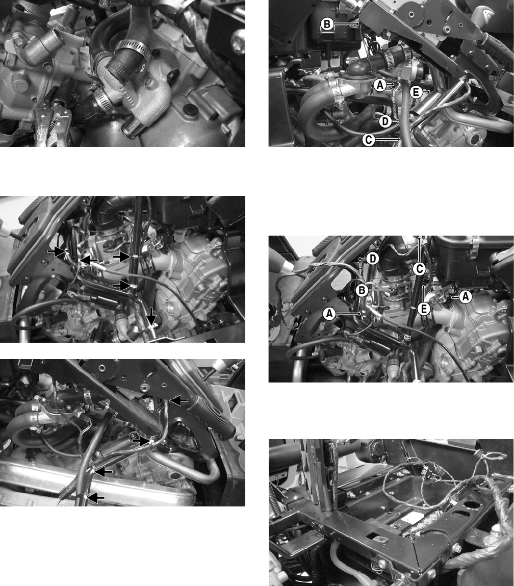
89
PR590
6. Mark all cable tie locations with an appropriate
marker; then remove the ties.
PR591A
PR592A
7. Disconnect the negative battery cable; then from the
right side, disconnect the engine coolant temperature
(ECT) sensor (A), inlet air temperature (IAT) sensor
(B), fuel pump/fuel gauge connector (C), rear igni-
tion coil (D), and throttle position sensor (TPS) con-
nector (E).
PR594A
8. Remove the rear spark plug cap; then from the left
side, remove the fuel injector connector (A), mani-
fold absolute pressure (MAP) sensor (B), parking
brake warning switch (C), reverse override switch
connector (D), and idle speed control (ISC) valve
(E).
PR595A
9. Disconnect the front ignition coil and remove the
front spark plug; then route the engine harness out of
the engine compartment.
PR596
10. From the left rear, disconnect the speed sensor con-
nector (F), stator coil connector (G), crankshaft posi-
tion (CKP) sensor (H), and gear position switch
connector (I).
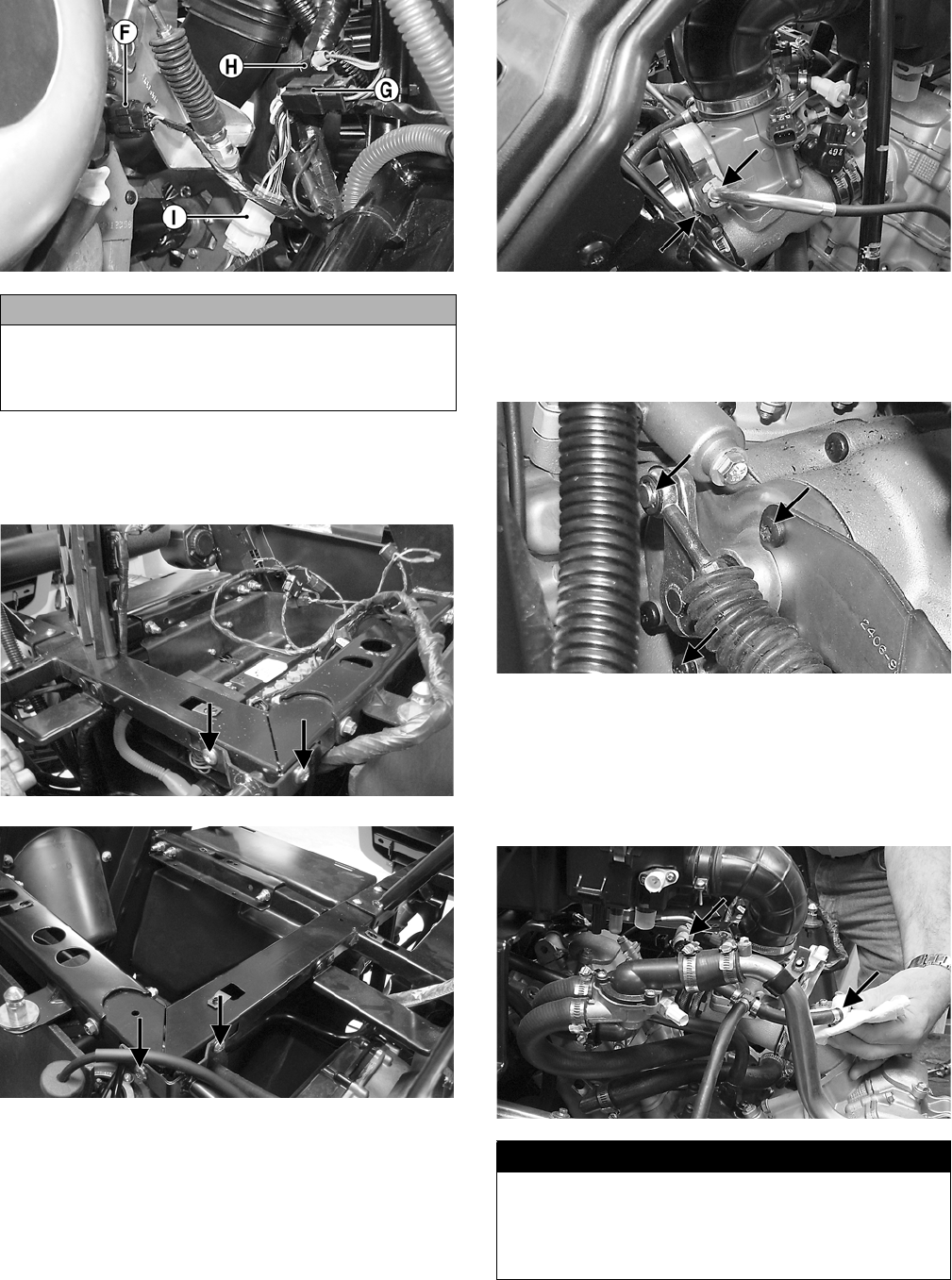
90
PR658A
11. Remove four mounting cap screws securing the shift
support assembly to the frame; then remove the cap
screw securing the upper coolant pipe support clamp
to the shift support.
PR596A
PR598A
12. Remove the machine screw securing the throttle arm
cover; then loosen the mounting nuts and disconnect
the throttle cable from the throttle body.
PR666A
13. Remove the E-clip from the transmission shift arm;
then remove the shifter cable mounting bracket from
the crankcase and move the shift support assembly
and cable to right side of the vehicle.
PR662A
NOTE: The parking brake cable does not need to be
disconnected.
14. Using a shop towel to absorb any spilled gasoline,
remove the “quick-disconnect” fuel couplers from
the fuel injectors.
PR663A
15. Remove four sheet metal screws securing the air fil-
ter mounting bracket to the frame; then loosen the
intake boot clamp and remove the air filter assembly.
CAUTION
The gear position switch wires are secured to the frame
with a nylon tie connector. This must be removed prior
to removing the engine/transmission or harness dam-
age will occur.
! WARNING
Always make certain the battery is disconnected and
the ignition key is removed before disconnecting fuel
system components. Gasoline could be accidentally
discharged by an activated fuel pump causing severe
injury or death.
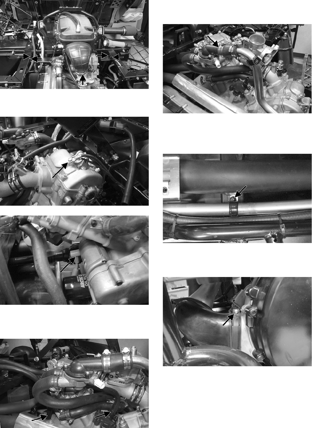
91
PR603A
16. Disconnect the engine/harness ground; then discon-
nect the starter cable from the starter.
PR604A
PR605A
17. Disconnect the crankcase breather hoses from the
crankcase and auxiliary drive cover and remove the
separator tank and breather hoses.
PR606A
18. Remove the upper radiator hose from the thermostat
housing; then move the coolant pipe to the left side
of the vehicle.
PR607A
19. Remove the sheet metal screws securing the constant
variable transmission (CVT) cooling duct to the
frame; then loosen the hose clamps and remove the
duct from the front elbow and CVT boot.
PR671A
20. Remove the inlet boot from the CVT cover; then
remove the outlet boot from the rear of the CVT
cover.
PR670A
21. Remove the oil cooler hoses from the fittings on the
oil filter base and crankcase; then plug the hoses and
cap the fittings.
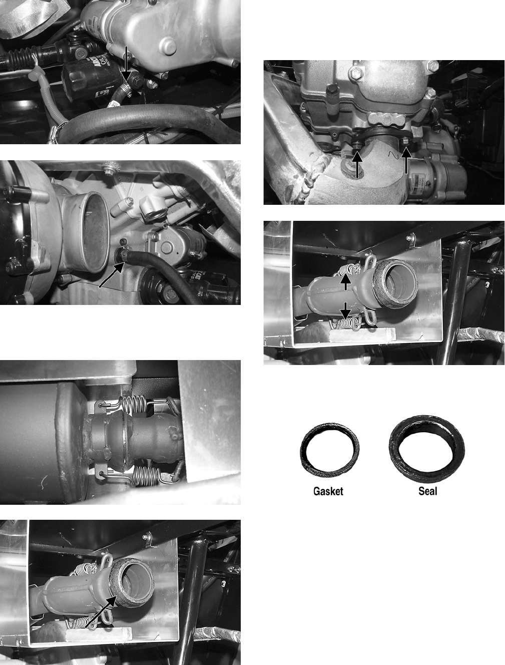
92
PR617A
PR616A’
22. Remove two springs securing the muffler to the
exhaust pipe and remove the muffler. Account for a
grafoil seal.
PR668
PR661B
23. Remove two cap screws securing the front exhaust
pipe to the cylinder head; then remove two springs
securing the front and rear exhaust pipes together.
Remove the front exhaust pipe. Account for a grafoil
seal and a grafoil gasket.
PR643A
PR661A
PR625A
NOTE: The grafoil gasket may remain in the cylinder
head.
24. Remove the cap screws securing the rear exhaust
pipe to the cylinder head and remove the exhaust
pipe. Account for a grafoil gasket.
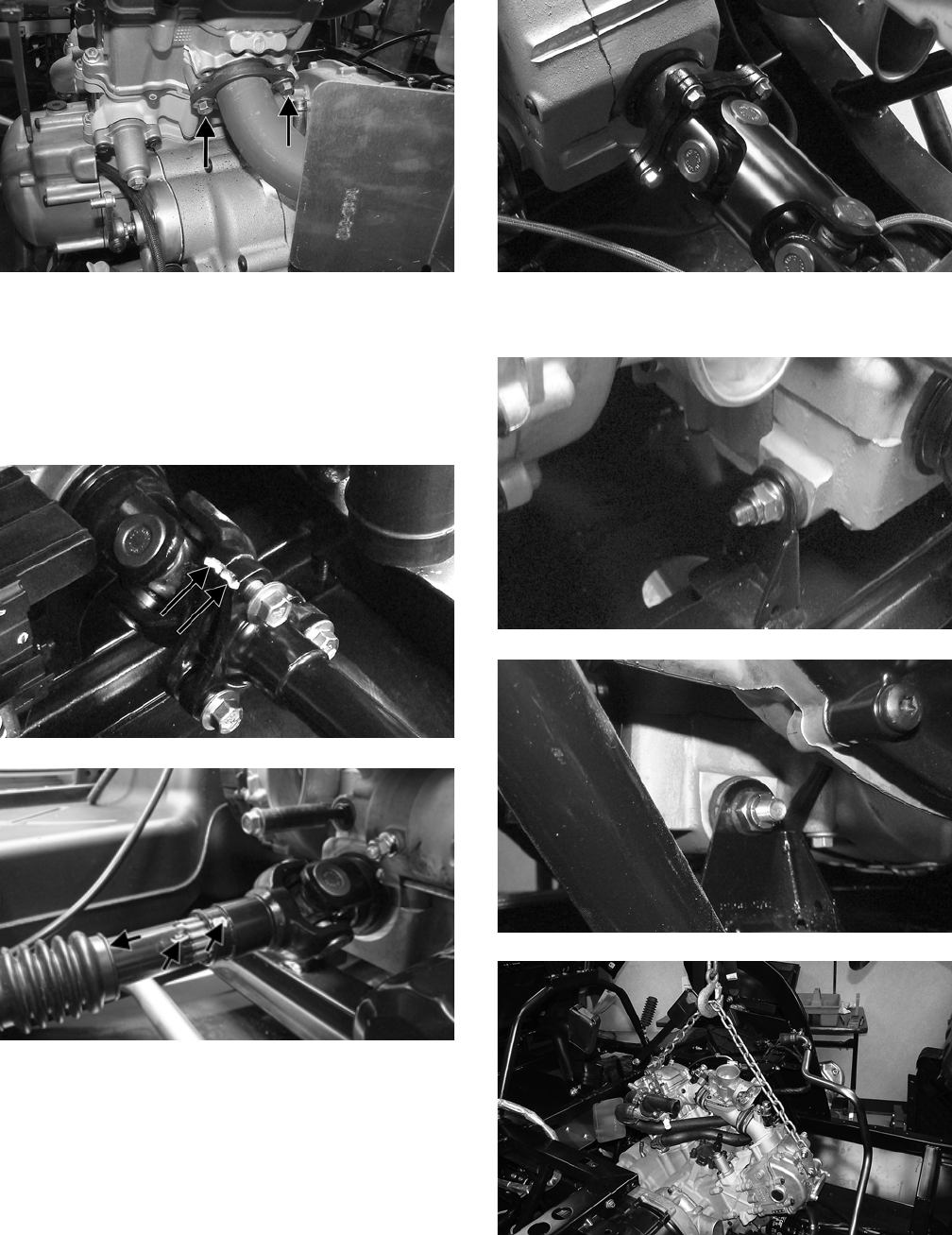
93
PR641A
NOTE: The grafoil gasket may remain in the cylinder
head.
25. Mark the components on the front driveshaft; then
remove the three cap screws securing the driveshaft
to the front differential. Slide the spline boot forward
and remove the driveshaft from the output yoke.
PR638A
PR639A
26. Remove four cap screws securing the rear driveshaft
to the output flange. The rear driveshaft can remain
on the vehicle.
PR647
27. Remove the lock nuts from the engine through-bolts;
then attach a lifting chain to the engine/transmission.
PR630
PR629
PR631
28. Using a suitable engine hoist, remove the weight
from the through-bolts; then remove the bolts.
Account for a flat washer on each bolt and noting the
front bolt is longer than the rear.
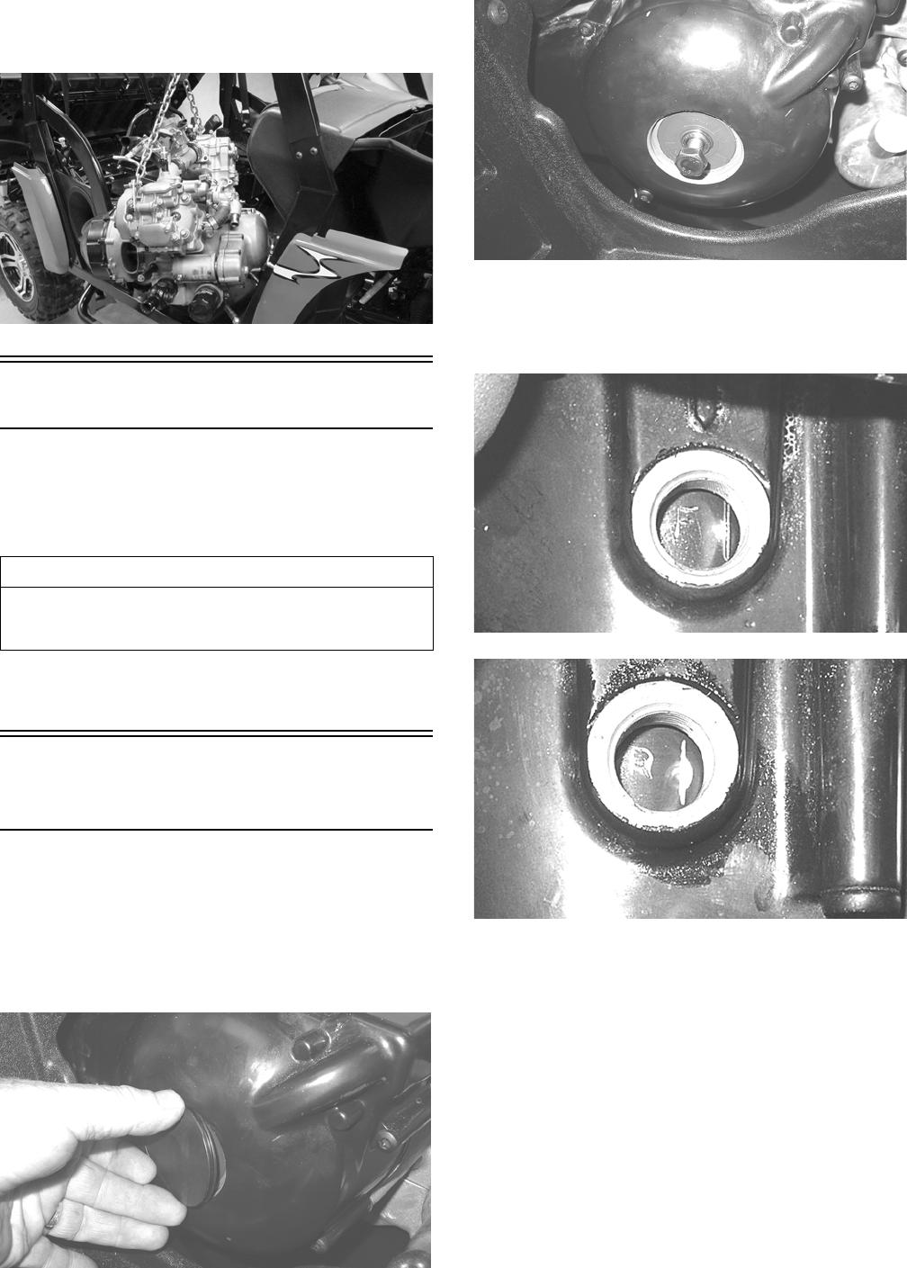
94
29. Lift the engine/transmission enough to clear the engine
mounting tabs on the frame; then remove the assembly
from the right side of the vehicle.
PR633
Top-Side Components
NOTE: For efficiency, it is preferable to remove and
disassemble only those components which need to be
addressed and to service only those components. The
technician should use discretion and sound judgment.
NOTE: The engine/transmission does not need to be
removed for this procedure.
Removing Top-Side
Components
A. Valve Cover/Rocker Arms
B. Cylinder Head/Camshaft
1. Remove the timing inspection plug, spark plugs, and
magneto housing cover; then install the 10 mm cap screw
(left-hand threads) in the crankshaft and rotate the desired
cylinder to top-dead-center of the compression stroke.
GZ027
GZ026
NOTE: Timing marks on the rotor/flywheel are
stamped with an “F” (front cylinder) and “R” (rear cyl-
inder) adjacent to the mark.
GZ063
GZ059
2. Remove the tappet covers on the cylinder being ser-
viced. The tappets should not have pressure on them.
3. Loosen the cap screws securing the valve cover to
the head.
AT THIS POINT
To service any one specific component, only limited dis-
assembly of components may be necessary. Note the
AT THIS POINT information in each sub-section.
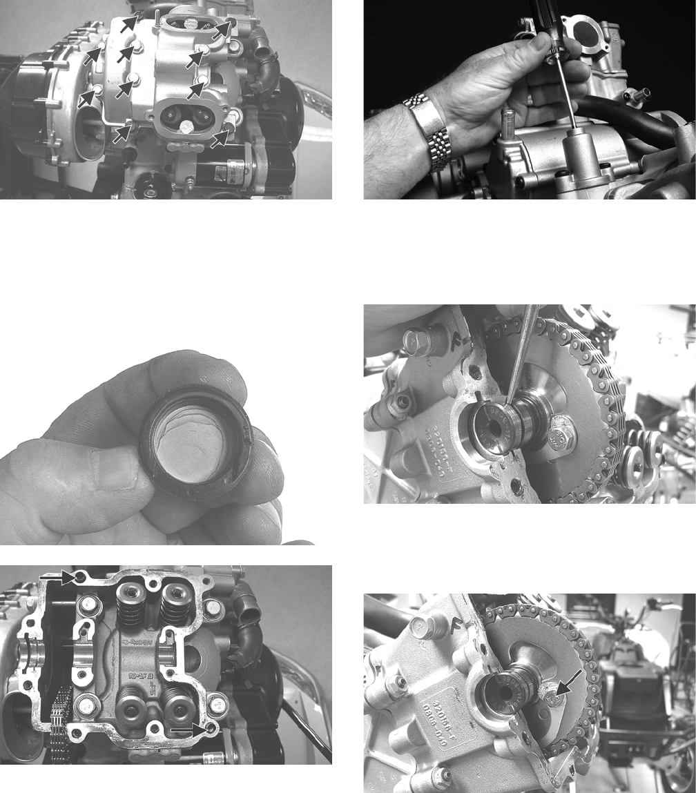
95
GZ126A
4. Remove all cap screws except the two top-side cap
screws next to the spark plug. These will keep the
alignment pins in place. Note the two rubber washers
on the remaining cap screws.
5. Remove the valve cover. Account for and note the
orientation of the cylinder head plug. Note the loca-
tion of the two alignment pins.
GZ162
GZ132A
6. Remove the cap screw on the end of the tensioner;
then using a flat-blade screwdriver, turn the tensioner
clockwise to remove the tension. Remove the two
cap screws securing the tensioner adjuster assembly
and remove the assembly. Account for a gasket.
GZ405
7. Using an awl, rotate the C-ring in its groove until it is
out of the cylinder head; then remove the C-ring.
NOTE: Care should be taken not to drop the C-ring
into the crankcase.
GZ155
8. Bend the washer tabs down and remove the two cap
screws securing the sprocket to the camshaft; then
drop the sprocket off the camshaft being careful not
to drop the locating pin into the engine.
GZ154A
9. While holding the chain, slide the sprocket and cam-
shaft out of the cylinder head.
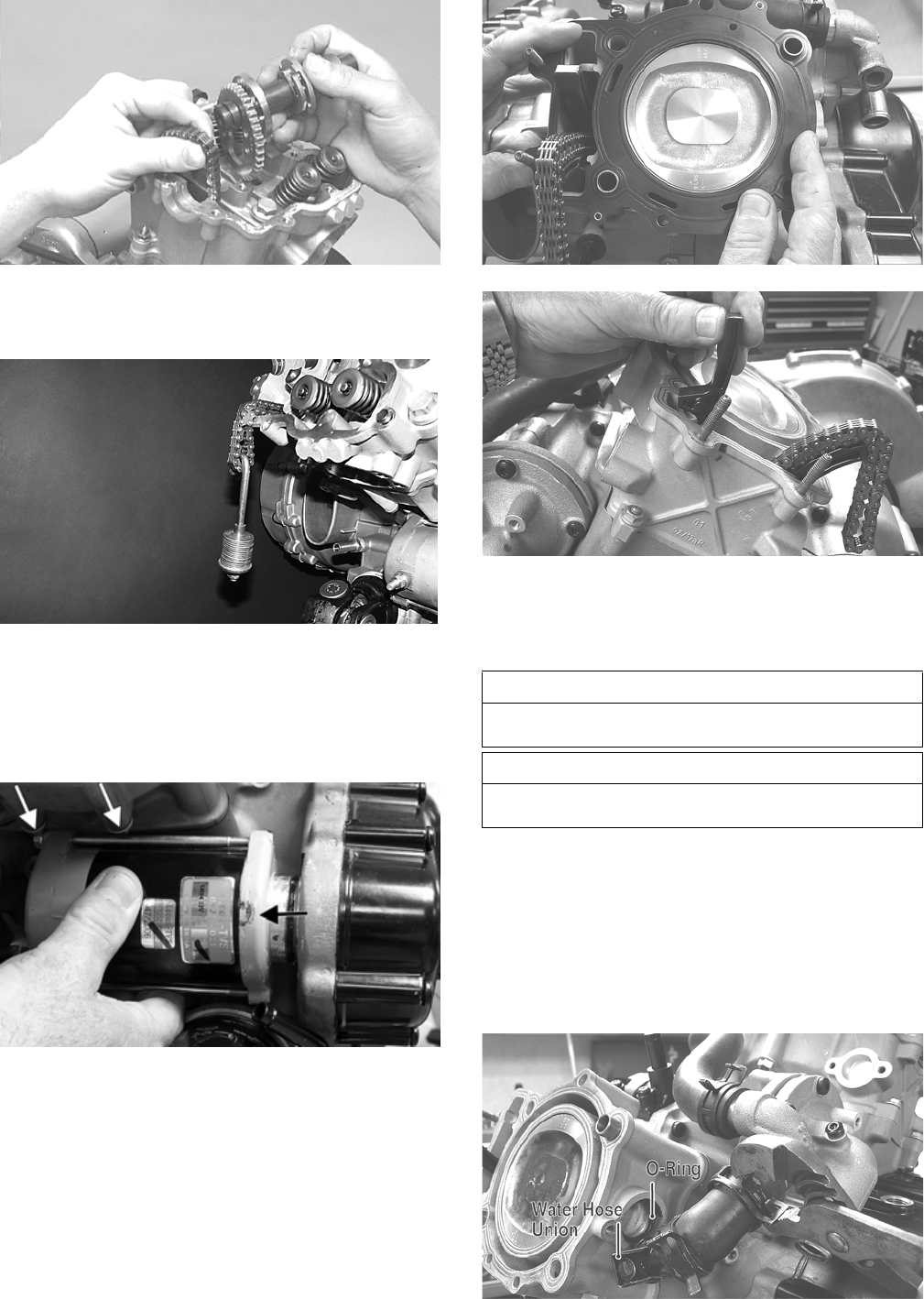
96
CC266D
NOTE: Loop the chain over the cylinder head and
secure it to keep it from falling into the crankcase.
GZ408
10. Remove the five nuts securing the cylinder head to
the cylinder; then remove the four cylinder head cap
screws and washers.
NOTE: Removing the starter will simplify removal of
the front cylinder base nuts.
GZ209A
11. Remove the cylinder head from the cylinder, remove
the gasket, and account for two alignment pins; then
remove the cam chain guide.
GZ151
GZ161
12. If the remaining cylinder head is to be serviced, apply
tension to the loose timing chain and rotate the second
cylinder to top-dead-center of the compression stroke;
then repeat steps 2-11 on the other cylinder head.
C. Cylinders
D. Pistons
NOTE: Steps 1-12 in the preceding sub-section
must precede this procedure.
13. Remove the cap screws securing the water hose
union to the cylinder; then remove the union from
the cylinder. Account for an O-ring.
GZ140A
AT THIS POINT
To service valves and cylinder head, see Servicing
Top-Side Components sub-section.
AT THIS POINT
To inspect cam chain guide, see Servicing Top-Side
Components sub-section.
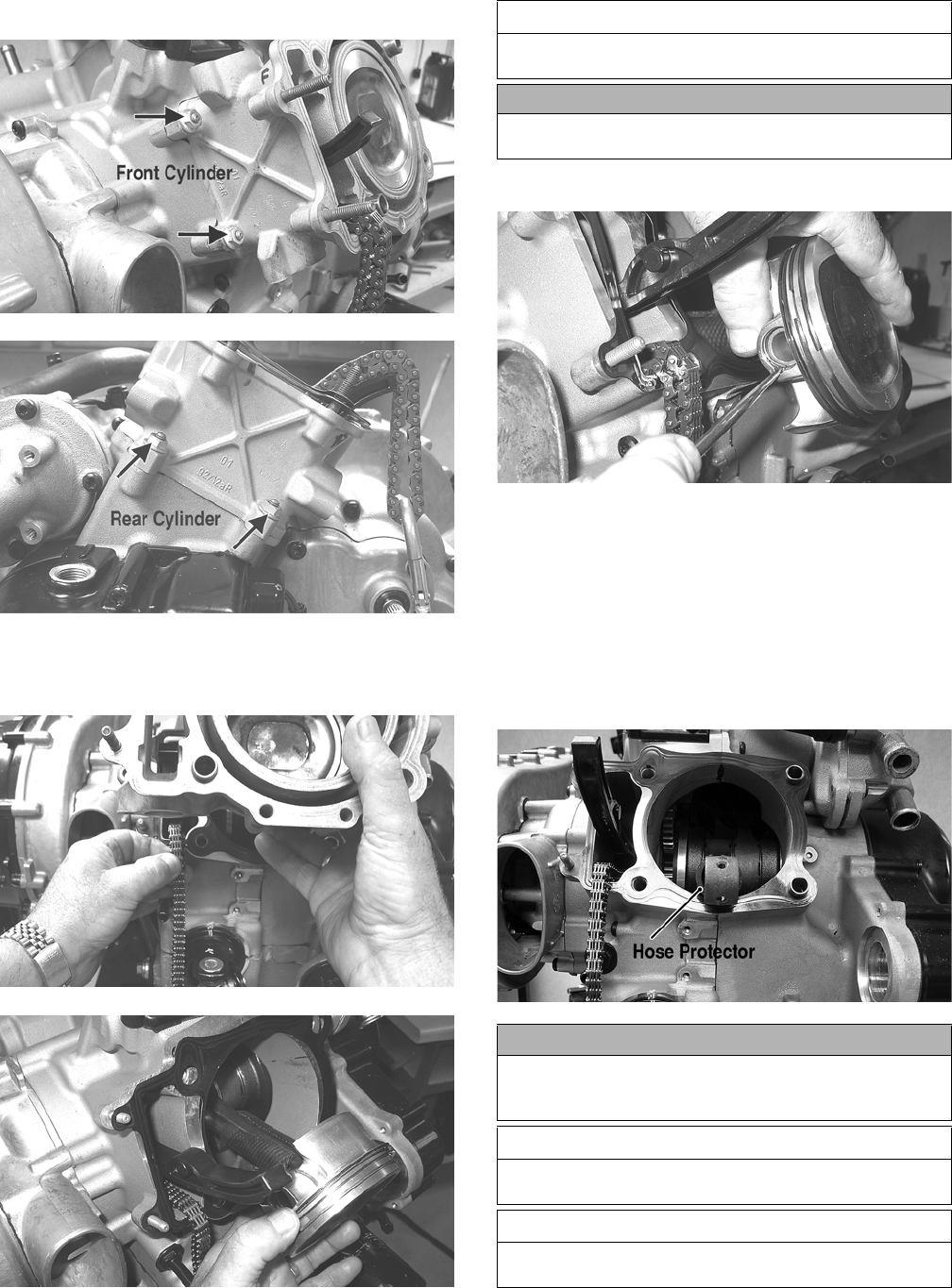
97
14. Remove the two nuts securing the cylinder to the
crankcase.
GZ141A
GZ160A
15. Lift the cylinder off the crankcase taking care not to
allow the piston to drop against the crankcase.
Account for the gasket and two alignment pins.
GZ142
GZ144
16. Using an awl, remove one piston-pin circlip.
GZ145
17. Using the Piston Pin Puller, remove the piston pin.
Account for the opposite-side circlip. Remove the
piston.
NOTE: It is advisable to remove the opposite-side
circlip prior to using the puller.
NOTE: Support the connecting rod with rubber
bands or a piece of hose to avoid damaging the rod
or install a suitable connecting rod holder.
GZ146A
AT THIS POINT
To service cylinder, see Servicing Top-Side Compo-
nents sub-section.
CAUTION
When removing the cylinder, be sure to support the pis-
ton to prevent damage to the crankcase and piston.
CAUTION
Do not allow the connecting rod to go down inside the
crankcase. If the rod is down inside the crankcase and
the crankshaft is rotated, severe damage will result.
AT THIS POINT
To service piston, see Servicing Top-Side Components
sub-section.
AT THIS POINT
To service center crankcase components only, proceed
to Removing Left-Side Components.
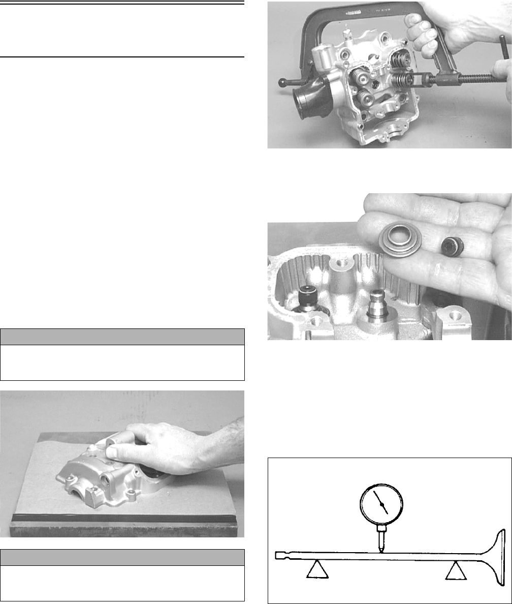
98
Servicing Top-Side
Components
VALVE ASSEMBLY
When servicing valve assembly, inspect valve seats, valve
stems, valve faces, and valve stem ends for pits, burn
marks, or other signs of abnormal wear.
NOTE: Whenever a valve is out of tolerance, it must
be replaced.
Cleaning/Inspecting Valve Cover
NOTE: If the valve cover cannot be trued, the cylin-
der head assembly must be replaced.
1. Wash the valve cover in parts-cleaning solvent.
2. Place the valve cover on the Surface Plate covered with
#400 grit wet-or-dry sandpaper. Using light pressure,
move the valve cover in a figure eight motion. Inspect
the sealing surface for any indication of high spots. A
high spot can be noted by a bright metallic finish. Cor-
rect any high spots before assembly by continuing to
move the valve cover in a figure eight motion until a uni-
form bright metallic finish is attained.
CC130D
Removing Valves
NOTE: Index all valves, springs, and cotters to their
original position when removing. When installing, all
valve components should be installed in their original
position.
1. Using a valve spring compressor, compress the valve
springs and remove the valve cotters. Account for an
upper spring retainer.
CC132D
2. Remove the valve seal and the lower remaining
spring seat. Discard the valve seal.
CC136D
NOTE: The valve seals must be replaced.
3. Remove the valve springs; then invert the cylinder
head and remove the valves.
Measuring Valve Stem Runout
1. Support each valve stem end with the V Blocks; then
check the valve stem runout using a dial indicator.
ATV-1082
2. Maximum runout must not exceed specifications.
Measuring Valve Stem
Outside Diameter
1. Using a micrometer, measure the valve stem outside
diameter.
2. Acceptable diameter ranges must be within specifi-
cations.
CAUTION
Do not remove an excessive amount of the sealing sur-
face or damage to the camshaft will result. Always check
camshaft clearance when resurfacing the valve cover.
CAUTION
Water or parts-cleaning solvent must be used in con-
junction with the wet-or-dry sandpaper or damage to
the sealing surface may result.
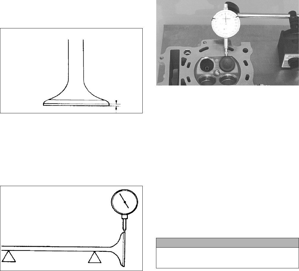
99
Measuring Valve Face/Seat Width
1. Using a micrometer, measure the width of the valve
face.
ATV-1004
2. Acceptable widths must be within specifications.
Measuring Valve Face Radial
Runout
1. Mount a dial indicator on the surface plate; then
place the valve stem on a set of V blocks.
2. Position the dial indicator contact point on the out-
side edge of the valve face; then zero the indicator.
ATV1082A
3. Rotate the valve in the V blocks.
4. Maximum runout must not exceed specifications.
Measuring Valve Guide/Valve Stem
Deflection (Wobble Method)
1. Mount a dial indicator and base on the surface plate;
then place the cylinder head on the surface plate.
2. Install the valve into the cylinder head; then position
the dial indicator contact point against the outside
edge of the valve face. Zero the indicator.
CC131D
3. Push the valve from side to side; then from top to
bottom.
4. Maximum “wobble” deflection must not exceed
specifications.
Measuring Valve Guide
(Inside Diameter)
1. Insert a suitable bore gauge 1/2 way into each valve
guide bore and record the measurement.
2. Acceptable inside diameter range must be within
specifications.
3. If a valve guide is out of tolerance, it must be
replaced.
Servicing Valves/Valve
Guides/Valve Seats
If valves, valve guides, or valve seats require servicing or
replacement, Arctic Cat recommends the components be
taken to a qualified machine shop for servicing.
Measuring Rocker Arm
(Inside Diameter)
1. Using a dial calipers, measure the inside diameter of
the rocker arm.
2. Acceptable inside diameter range must be within
specifications.
Measuring Rocker Arm Shaft
(Outside Diameter)
1. Using a micrometer, measure the outside diameter of
the rocker arm shaft.
2. Acceptable outside diameter must be at or above
specifications.
Installing Valves
1. Apply grease to the inside surface of the valve seals;
then place a lower spring seat and valve guide seal
over each valve guide.
CAUTION
If valves are discolored or pitted or if the seating sur-
face is worn, the valve must be replaced. Do not attempt
to grind the valves or severe engine damage may occur.
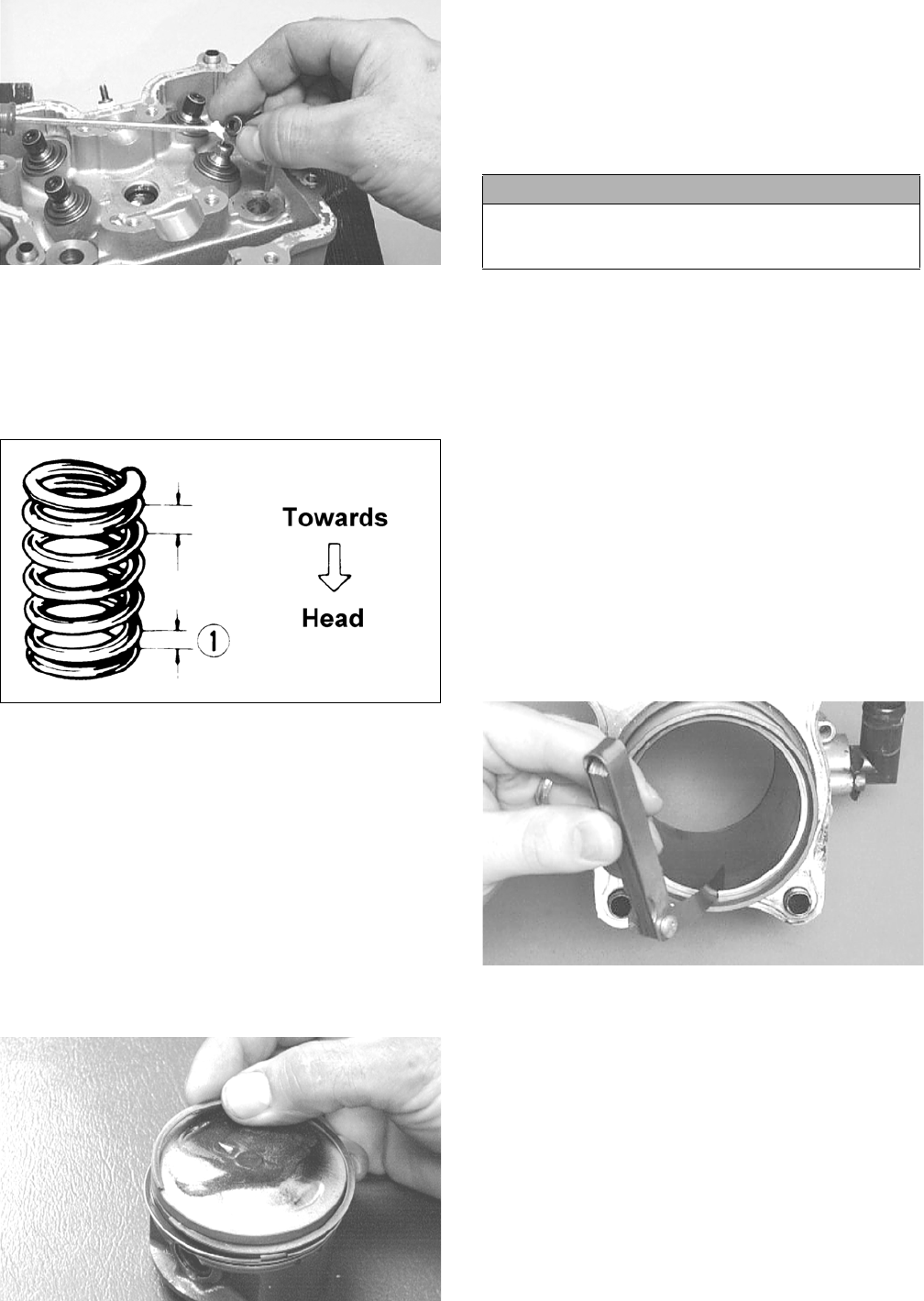
100
CC144D
2. Insert each valve into its original location.
3. Install the valve springs with the painted end of the
spring facing away from the cylinder head.
NOTE: If the paint is not visible, install the ends of the
springs with the closest wound coils toward the head.
ATV-1011A
4. Place a spring retainer over the valve springs; then
using the valve spring compressor, compress the
valve springs and install the valve cotters.
PISTON ASSEMBLY
NOTE: Whenever a piston or pin is out of tolerance,
it must be replaced.
Removing Piston Rings
1. Starting with the top ring, slide one end of the ring
out of the ring-groove.
2. Remove each ring by working it toward the dome of
the piston while rotating it out of the groove.
CC400D
Cleaning/Inspecting Piston
1. Take an old piston ring and snap it into two pieces;
then grind the end of the old ring to a 45° angle and
to a sharp edge.
2. Using the sharpened ring as a tool, clean carbon from
the ring-grooves. Be sure to position the ring with its
tapered side up.
3. Using a non-metallic carbon removal tool, remove
any carbon buildup from the dome of the piston.
4. Inspect the piston for cracks in the piston pin, dome,
and skirt areas.
5. Inspect the piston for seizure marks or scuffing.
6. Inspect the perimeter of each piston for signs of
excessive “blowby.” Excessive “blowby” indicates
worn piston rings or an out-of-round cylinder.
Measuring Piston-Ring End Gap
(Installed)
1. Place each compression ring in the wear portion of
the cylinder. Use the piston to position each ring
squarely in the cylinder.
2. Using a feeler gauge, measure each piston-ring end
gap. Acceptable ring end gap must not exceed speci-
fications.
CC280D
Measuring Piston Pin (Outside
Diameter) and Piston-Pin Bore
1. Measure the piston pin outside diameter at each end
and in the center. If measurement exceeds specifica-
tions, the piston pin must be replaced.
CAUTION
Improper cleaning of the ring-grooves by the use of the
wrong type of ring-groove cleaner will result in severe
damage to the piston.
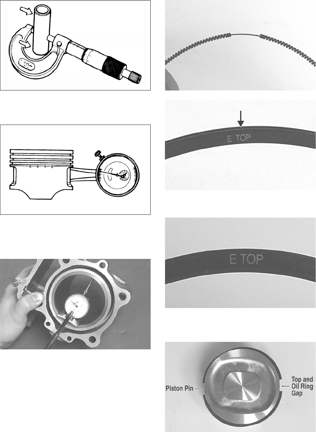
101
ATV-1070
2. Insert an inside dial indicator into the piston-pin
bore. The diameter must not exceed specifications.
Take two measurements to ensure accuracy.
ATV-1069
Measuring Piston Skirt/Cylinder
Clearance
1. Measure the cylinder front to back in six places.
CC127D
2. Measure the corresponding piston diameter at a point
15 mm (0.6 in.) above the piston skirt at a right angle
to the piston-pin bore. Subtract this measurement
from the measurement in step 1. The difference
(clearance) must not exceed specifications.
Installing Piston Rings
1. Install the expander spring making sure the ends are
aligned on the wire; then install the oil ring with the
ring gap 90° from the spring gap and the marking “E
TOP” directed toward the top of the piston.
GZ168
GZ169A
2. Install the second compression ring with the marking
“E TOP” directed toward the top of the piston.
GZ167
3. Install the first (unmarked) compression ring; then
rotate the rings so the ring gaps are approximately
180° apart and oriented to the piston pin.
GZ187A
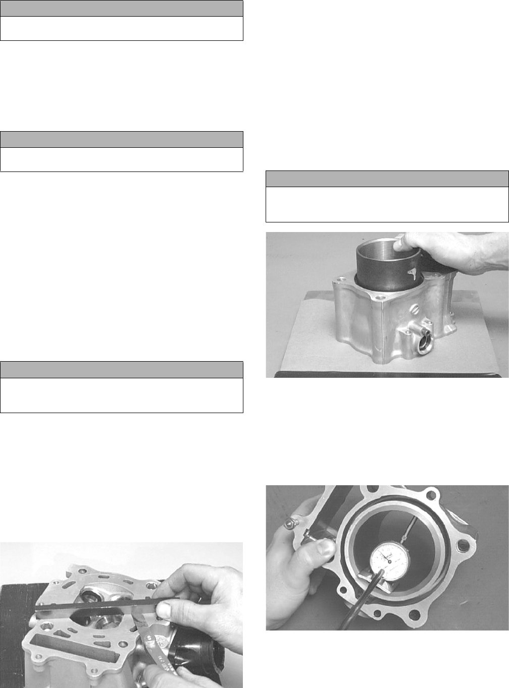
102
CYLINDER/CYLINDER HEAD
ASSEMBLY
NOTE: If the cylinder/cylinder head cannot be trued,
they must be replaced as an assembly.
Cleaning/Inspecting Cylinder Head
1. Using a non-metallic carbon removal tool, remove
any carbon buildup from the combustion chamber
being careful not to nick, scrape, or damage the com-
bustion chamber or the sealing surface.
2. Inspect the spark plug hole for any damaged threads.
Repair damaged threads using a “heli-coil” insert.
3. Place the cylinder head on the surface plate covered
with #400 grit wet-or-dry sandpaper. Using light
pressure, move the cylinder head in a figure eight
motion. Inspect the sealing surface for any indication
of high spots. A high spot can be noted by a bright
metallic finish. Correct any high spots before assem-
bly by continuing to move the cylinder head in a fig-
ure eight motion until a uniform bright metallic
finish is attained.
Measuring Cylinder Head
Distortion
1. Remove any carbon buildup in the combustion
chamber.
2. Lay a straightedge across the cylinder head; then
using a feeler gauge, check the distortion between
the head and the straightedge.
3. Maximum distortion must not exceed specifications.
CC141D
Cleaning/Inspecting Cylinder
1. Wash the cylinder in parts-cleaning solvent.
2. Inspect the cylinder for pitting, scoring, scuffing,
warpage, and corrosion. If marks are found, repair
the surface using a cylinder hone (see Inspecting
Cylinder in this sub-section).
3. Place the cylinder on the surface plate covered with
#400 grit wet-or-dry sandpaper. Using light pressure,
move the cylinder in a figure eight motion. Inspect
the sealing surface for any indication of high spots.
A high spot can be noted by a bright metallic finish.
Correct any high spots before assembly by continu-
ing to move the cylinder in a figure eight motion
until a uniform bright metallic finish is attained.
CC129D
4. Using a slide gauge and a dial indicator or a snap
gauge, measure the cylinder bore diameter in three
locations from top to bottom and again from top to
bottom at 90° from the first measurements for a total
of six measurements. The trueness (out-of-round-
ness) is the difference between the highest and low-
est reading. Maximum trueness (out-of-roundness)
must not exceed specifications.
CC127D
5. Wash the cylinder in parts-cleaning solvent.
6. Inspect the cylinder for pitting, scoring, scuffing, and
corrosion. If marks are found, repair the surface
using a #320 grit ball hone.
CAUTION
Incorrect installation of the piston rings will result in
engine damage.
CAUTION
The cylinder head studs must be removed for this pro-
cedure.
CAUTION
Water or parts-cleaning solvent must be used in con-
junction with the wet-or-dry sandpaper or damage to
the sealing surface may result.
CAUTION
Water or parts-cleaning solvent must be used in con-
junction with the wet-or-dry sandpaper or damage to
the sealing surface may result.
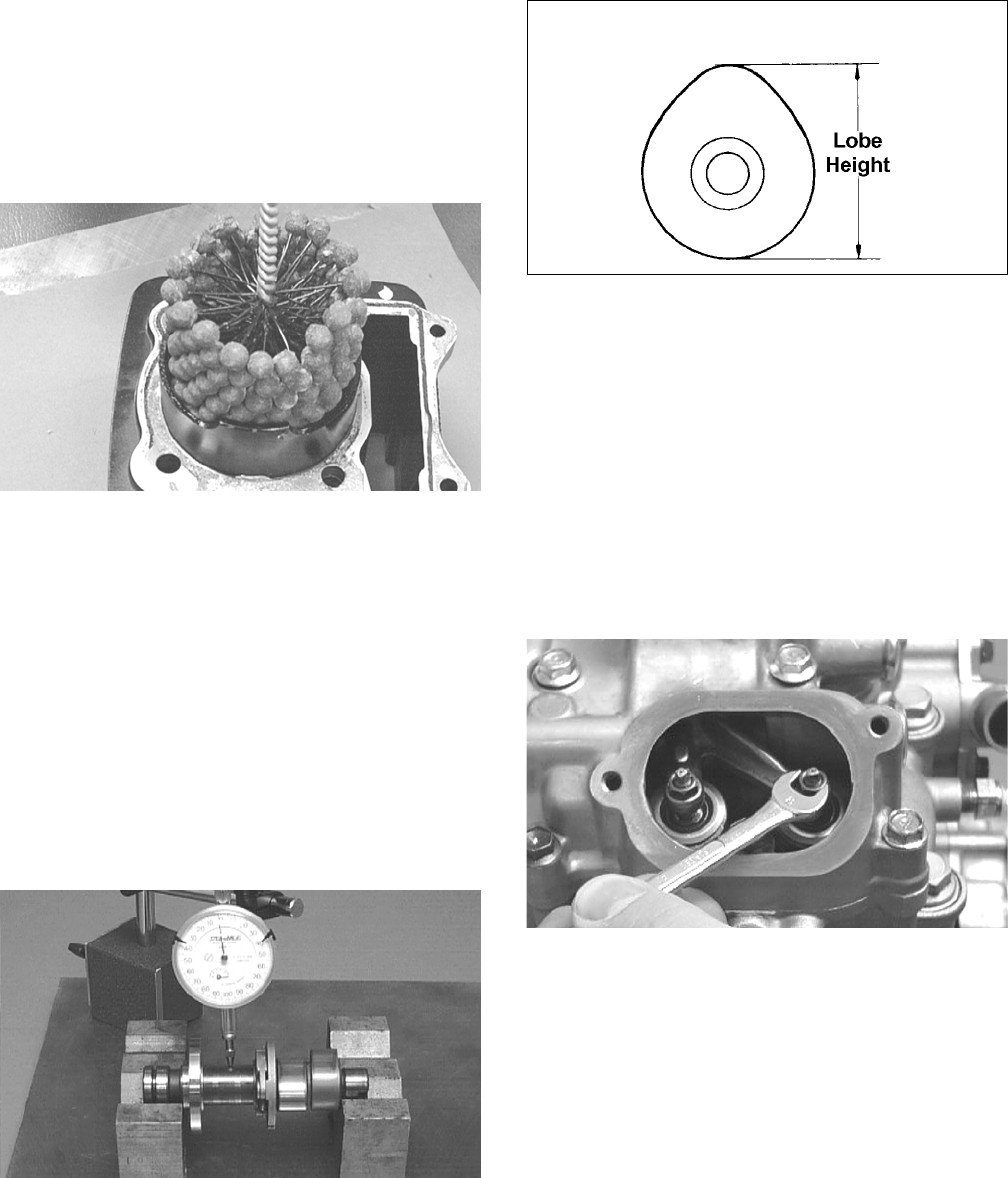
103
NOTE: To produce the proper 60° cross-hatch pat-
tern, use a low RPM drill (600 RPM) at the rate of 30
strokes per minute. If honing oil is not available, use
a lightweight petroleum-based oil. Thoroughly clean
cylinder after honing using soap and hot water. Dry
with compressed air; then immediately apply oil to
the cylinder bore. If the bore is severely damaged or
gouged, replace the cylinder.
CC390D
7. If any measurement exceeds the limit, replace the
cylinder and piston.
Inspecting Cam Chain Guide
1. Inspect cam chain guide for cuts, tears, breaks, or
chips.
2. If the chain guide is damaged, it must be replaced.
Measuring Camshaft Runout
NOTE: If the camshaft is out of tolerance, it must be
replaced.
1. Place the camshaft on a set of V blocks; then position
the dial indicator contact point against the shaft and
zero the indicator.
CC283D
2. Rotate the camshaft and note runout; maximum run-
out must not exceed specifications.
Measuring Camshaft Lobe Height
1. Using a calipers, measure each cam lobe height.
ATV1013A
2. The lobe heights must be greater than minimum
specifications.
Inspecting Camshaft Bearing
Journal
1. Inspect the bearing journal for scoring, seizure
marks, or pitting.
2. If excessive scoring, seizure marks, or pitting is
found, the cylinder head assembly must be replaced.
Measuring Camshaft to Cylinder
Head Clearance
1. Remove the adjuster screws and jam nuts.
CC005D
2. Place a strip of plasti-gauge in each of the camshaft
lands in the cylinder head.
3. Place the valve cover on the cylinder head and secure
with the valve cover cap screws. Tighten securely.
NOTE: Do not rotate the camshaft when measuring
clearance.
4. Remove the cap screws securing the valve cover to
the cylinder; then remove the valve cover and cam-
shaft.
5. Match the width of the plasti-gauge with the chart
found on the plasti-gauge packaging to determine
camshaft to cylinder head and valve cover clearance.
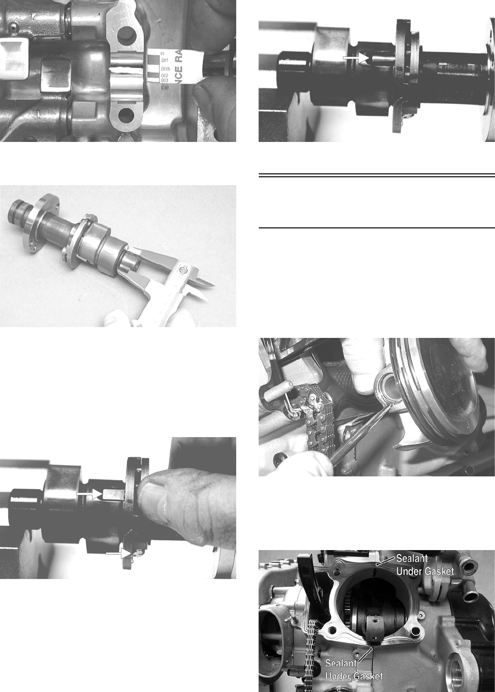
104
CC145D
6. If clearance is excessive, measure the journals of the
camshaft.
CC287D
NOTE: If the journals are worn, replace the cam-
shaft; then measure the clearance again. If it is still
out of tolerance, replace the cylinder head.
Inspecting Camshaft Spring/Drive
Pin (Front Camshaft Only)
1. Inspect the spring and drive pin for damage.
CF061A
CF060A
2. If damaged, the camshaft must be replaced.
Installing Top-Side
Components
A. Pistons
B. Cylinders
1. Install the piston on the connecting rod making sure
the circlip on each side is fully seated in the piston.
NOTE: The piston should be installed so the arrow
points toward the exhaust of the respective cylinder.
GZ166
2. Place the two alignment pins into position. Place the cyl-
inder gasket into position with a drop of silicone sealant
at the front and rear crankcase junction; then place a pis-
ton holder (or suitable substitute) beneath the piston skirt
and square the piston in respect to the crankcase.
GZ146B
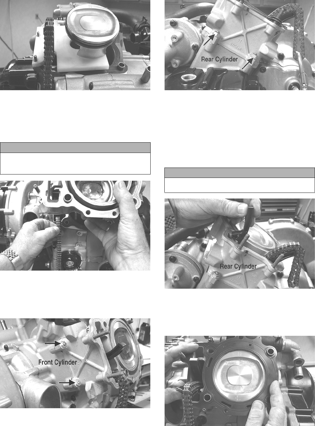
105
GZ159
3. Lubricate the inside wall of the cylinder; then using a
ring compressor, compress the rings and slide the
cylinder over the piston. Route the cam chain up
through the cylinder cam chain housing; then remove
the piston holder and seat the cylinder firmly on the
crankcase.
GZ142
4. Loosely install the two nuts securing the cylinder to
the crankcase.
NOTE: The two cylinder-to-crankcase nuts will be
tightened in step 10.
GZ141A
GZ160A
5. Install the coolant hose onto the crankcase union and
tighten the clamp.
C. Cylinder Head
D. Valve Cover
NOTE: Steps 1-5 in the preceding sub-section must
precede this procedure.
6. Place the chain guide into the cylinder.
GZ161A
7. Place a new head gasket into position on the cylin-
der. Place the alignment pins into position; then
place the head assembly into position on the cylinder
while guiding the cam chain through the cylinder
head.
GZ151
CAUTION
The cylinder should slide on easily. Do not force the cyl-
inder or damage to the piston, rings, cylinder, or crank-
shaft assembly may occur. CAUTION
Care should be taken that the bottom of the chain guide
is secured in the crankcase boss.
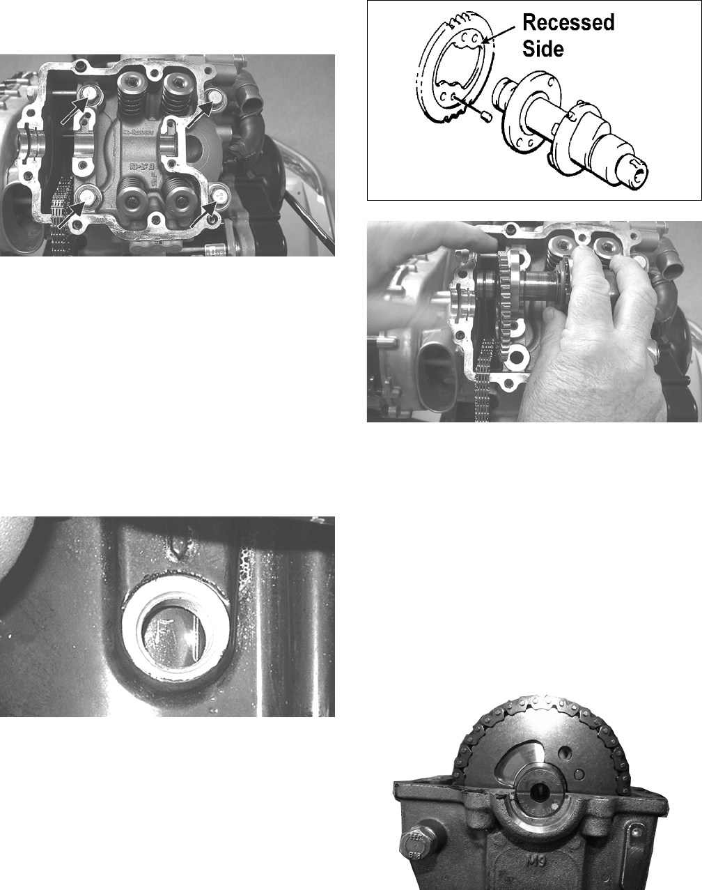
106
8. Apply a light coat of grease to the cylinder head cap
screw threads and washers; then install the cap
screws. Tighten only until snug.
GZ132B
9. Loosely install the five cylinder head nuts.
10. In a crisscross pattern, tighten the four cylinder head
cap screws (from step 8) initially to 20 ft-lb; then
increase to 30 ft-lb, and finally to 37 ft-lb. Tighten
the 8 mm nut (from step 9) to 21 ft-lb; then using a
crisscross pattern, tighten the 6 mm nuts (from step
9) to 8.5 ft-lb. Tighten the two cylinder-to-crankcase
nuts (from step 4) to 8 ft-lb.
NOTE: If both cylinders have been removed, repeat
steps 1-10 for the remaining cylinder.
11. With the timing inspection plug removed and the
front chain held tight, rotate the crankshaft until the
front piston is at TDC indicated by timing mark F.
GZ063
12. With the alignment pin installed in the front cam-
shaft, loosely place the cam sprocket (with the
recessed side facing the cam shaft lobes) onto the
camshaft. At this point, do not “seat” the sprocket
onto the shaft.
732-307B
GZ130
NOTE: At this point, oil the camshaft bearings, cam
lobes, and the three seating journals on the cylinder.
13. With the cam lobes directed down (toward the pis-
ton), maneuver the camshaft/sprocket assembly
through the chain and towards its seating position;
then loop the chain over the sprocket.
NOTE: Note the position of the alignment marks on
the end of the camshaft. They must be parallel to the
valve cover mating surface. If rotating the camshaft is
necessary for alignment, rotate the sprocket inside
the chain until the alignment pin can be engaged in
the sprocket with the camshaft properly aligned to
the head.
GZ519
14. Seat the cam sprocket onto the camshaft making sure
the alignment pin in the camshaft aligns with the
smallest hole in the sprocket; then place the cam-
shaft/sprocket assembly onto the cylinder ensuring
the following.
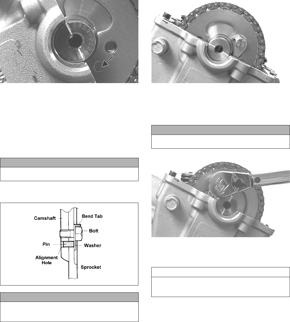
107
GZ190B
A. Piston still at top-dead-center.
B. Camshaft lobes directed down (toward the piston).
C. Camshaft alignment marks parallel to the valve
cover mating surface.
D. Recessed side of the sprocket directed toward the
cam lobes.
E. Camshaft alignment pin and sprocket alignment
hole (smallest) are aligned.
15. Place the tab-washer onto the sprocket making sure it
covers the pin in the alignment hole.
ATV1027
16. Install the first cap screw (threads coated with red
Loctite #271) securing the sprocket and tab-washer
to the camshaft. Tighten only until snug.
GZ195
17. Keeping tension on the opposite cam chain, rotate the
crankshaft until the second cap screw securing the
sprocket to the camshaft can be installed; then install the
cap screw (threads coated with red Loctite #271) and
tighten to 11 ft-lb. Bend the tab to secure the cap screw.
GZ193
18. Rotate the crankshaft until the first cap screw (from
step 16) can be tightened; then tighten to 11 ft-lb.
Bend the tab to secure the cap screw.
19. Keeping tension on the rear cam chain, rotate the
engine forward 270° until rear piston is at TDC indi-
cated by timing mark R.
CAUTION
If any of the above factors are not as stated, go back to
step 11 and carefully proceed.
CAUTION
Care must be taken that the tab-washer is installed cor-
rectly to cover the alignment hole on the sprocket. If the
alignment pin falls out, severe engine damage will result.
CAUTION
Failure to keep tension on any loose cam chain may
cause severe engine damage.
AT THIS POINT
Return the engine to TDC on the front cylinder making
sure the cam lobes are directed downward to ensure
correct starting point for step 19.
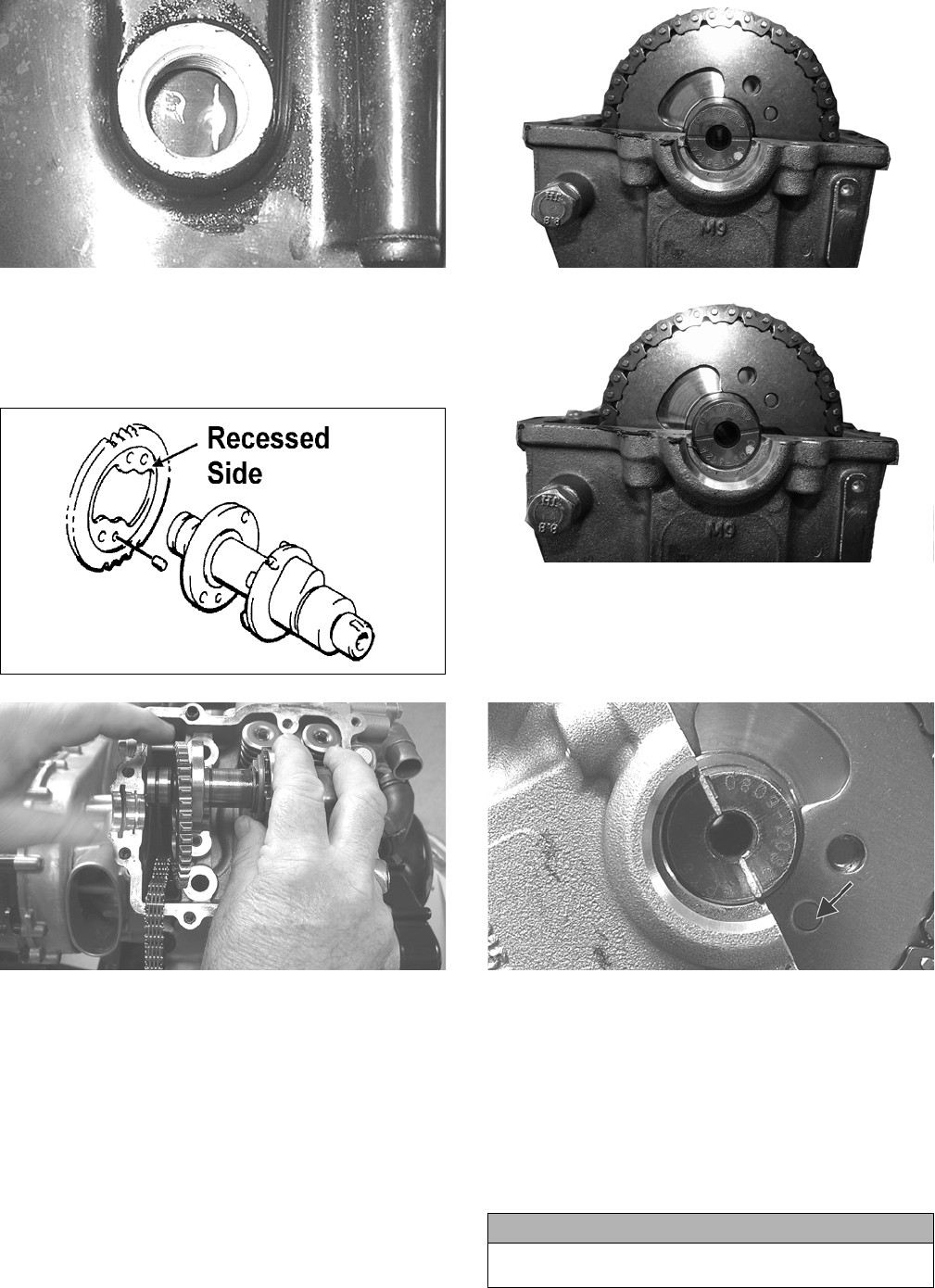
108
GZ059
20. With the alignment pin installed in the rear camshaft,
loosely place the cam sprocket (with the recessed
side facing the cam shaft lobes) onto the camshaft.
At this point, do not “seat” the sprocket onto the
shaft.
732-307B
GZ130
NOTE: At this point, oil the camshaft bearings, cam
lobes, and the three seating journals on the cylinder.
21. With the cam lobes directed down (toward the pis-
ton), maneuver the camshaft/sprocket assembly
through the chain and towards its seating position;
then loop the chain over the sprocket.
NOTE: Note the position of the alignment marks on
the end of the camshaft. They should be parallel with
the plane of the cylinder head. If rotating the cam-
shaft is necessary for alignment, rotate the sprocket
inside the chain until the alignment pin can be
engaged in the sprocket with the camshaft in the
nearest possible position to parallel.
GZ519
GZ518
22. Seat the cam sprocket onto the camshaft making sure
the alignment pin in the camshaft aligns with the
smallest hole in the sprocket; then place the cam-
shaft/sprocket assembly onto the cylinder ensuring
the following.
GZ190B
A. Piston still at top-dead-center.
B. Camshaft lobes directed down (toward the piston).
C. Camshaft alignment marks parallel to the valve
cover mating surface.
D. Recessed side of the sprocket directed toward the
cam lobes.
E. Camshaft alignment pin and sprocket alignment
hole (smallest) are aligned.
CAUTION
If any of the above factors are not as stated go back to
step 19 and carefully proceed.
CORRECT
INCORRECT
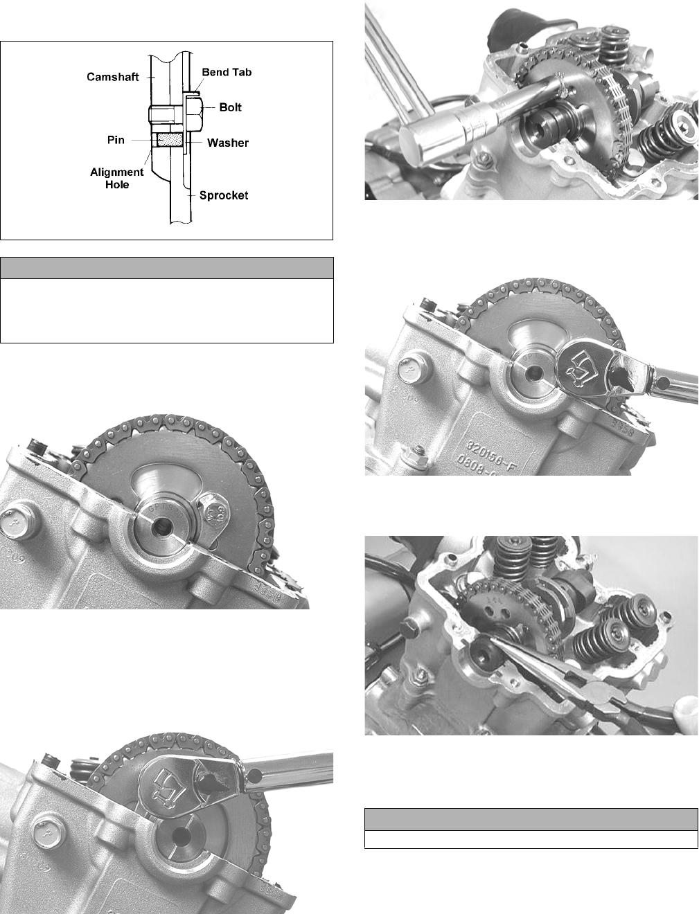
109
23. Place tab-washer onto the sprocket making sure it
covers the pin in the alignment hole.
ATV-1027
24. Install the first cap screw (threads coated with red
Loctite #271) securing the sprocket and tab-washer
to the camshaft. Tighten only until snug.
GZ195
25. Rotate the crankshaft until the second cap screw
securing the sprocket to the camshaft can be
installed; then install the cap screw (threads coated
with red Loctite #271) and tighten to 11 ft-lb. Bend
the tab to secure the cap screw.
GZ193
CD465
26. Rotate the crankshaft until the first cap screw (from
step 23) can be addressed; then tighten to 11 ft-lb.
Bend the tab to secure the cap screw.
GZ194
27. Place the C-rings into position in their grooves in the
cylinder heads.
CC012D
28. Install the cylinder head plugs in the cylinder heads
with the open end facing downward and toward the
inside.
CAUTION
Care must be taken that the tab-washer is installed cor-
rectly to cover the alignment hole on the sprocket. If the
alignment pin falls out, severe engine damage will
result.
CAUTION
The open end of the plug must be positioned downward.
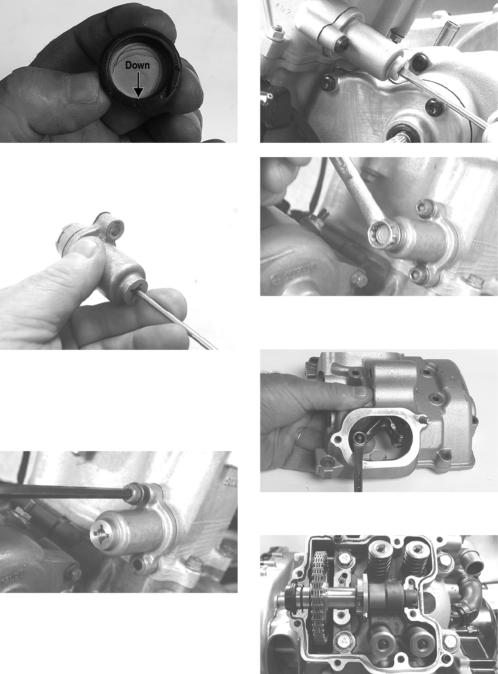
110
GZ162A
29. Remove the cap screw from the end of the chain ten-
sioner; then using a flat-blade screwdriver, rotate the
adjuster screw inside the tensioner clockwise until
the screw bottoms.
CD501
NOTE: The adjuster shaft will be drawn into the ten-
sioner as the adjuster screw is rotated clockwise. The
adjuster shaft tension will be released in step 30.
30. Place the chain tensioner adjuster assembly and gas-
ket into position on the cylinder and secure with the
two cap screws.
CD469
31. Using a flat-blade screwdriver, rotate the adjuster
screw inside the tensioner counterclockwise until the
tensioner spring bears tension; then install the cap
screw into the end of the chain tensioner.
GZ201
CD471
32. Loosen the four adjuster screw jam nuts; then loosen
the four adjuster screws on the rocker arms in the
valve cover.
GZ199
33. Apply a thin coat of Three Bond Sealant to the mat-
ing surfaces of the cylinder heads.
GZ202
34. Lubricate the camshaft journals and lobes with
engine oil; then place the valve cover into position.
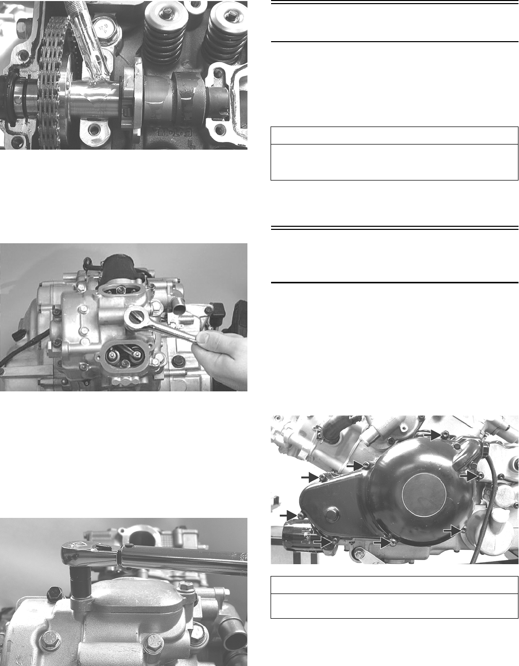
111
GZ206
NOTE: At this point, the rocker arms and adjuster
screws must not have pressure on them.
35. Install the top side cap screws with rubber washers;
then install the remaining cap screws. Tighten only
until snug.
CC003D
36. In a crisscross pattern starting from the center and
working outward, tighten the cap screws on both
valve covers to 8.5 ft-lb.
37. Adjust valve/tappet clearance (see Periodic Mainte-
nance/Tune-Up).
38. Place the tappet covers into position on the valve
cover making sure the O-rings are properly installed.
Tighten the cap screws to 9 ft-lb.
GZ208
39. If removed, install the spark plugs. Tighten securely.
Left-Side Components
NOTE: For efficiency, it is preferable to remove and
disassemble only those components which need to
be addressed and to service only those components.
The technician should use discretion and sound
judgment.
NOTE: The engine/transmission does not have to
be removed from the frame for this procedure.
Removing Left-Side
Components
A. Magneto Cover/Stator Coils
B. Water Pump
C. Shifter Assembly
D. Rotor/Flywheel/Starter Clutch
E. Speed Sensor/Trigger Assembly
1. Remove the cap screws securing the magneto cover
to the crankcase; then remove the magneto cover.
Account for the gasket.
GZ212A
2. Remove the starter motor, starter driven gear (A),
starter countershaft bushing (B), and starter counter-
shaft gear (C); then remove the starter gear shafts (D)
noting the longer shaft is nearest the starter.
AT THIS POINT
To service any one specific component, only limited dis-
assembly of components may be necessary. Note the
AT THIS POINT information in each sub-section.
AT THIS POINT
To replace stator coils/crankshaft position sensor, see
Electrical System.
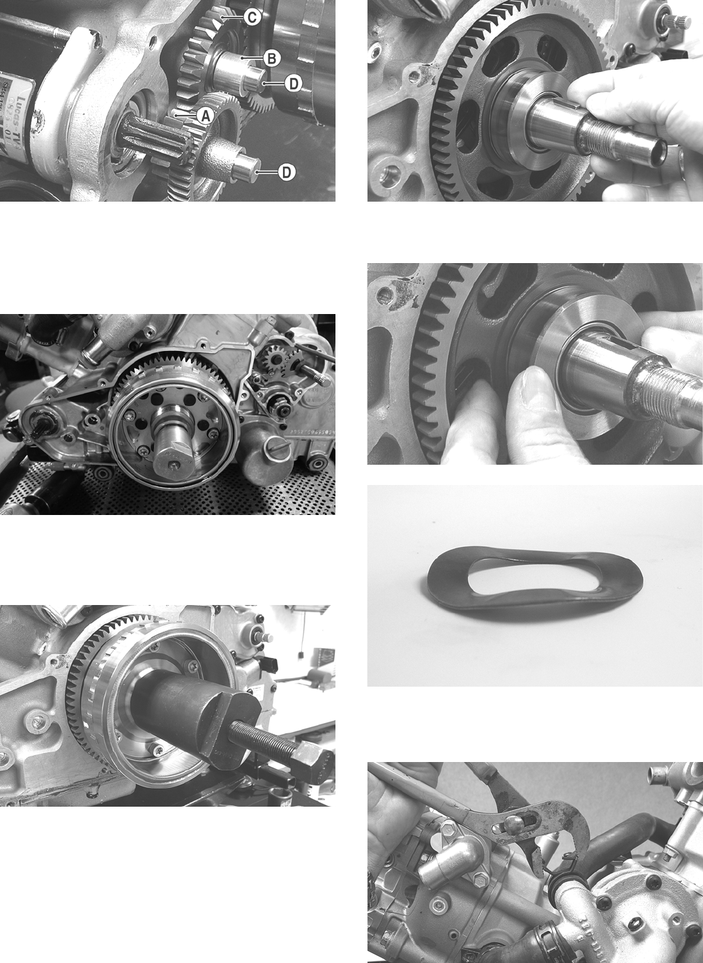
112
GZ224A
NOTE: The starter is not serviceable and must be
replaced as a complete assembly.
3. Remove the rotor/flywheel nut; then install the
appropriate crankshaft protector into the crankshaft.
H2-018
4. Install Magneto Rotor Remover Set and loosen the
rotor/flywheel; then remove the crankshaft protector
and rotor/flywheel from the crankshaft. Account for
the flywheel key.
GZ216
GZ217
5. With the flywheel key removed, remove the starter
ring-gear and spacer washer.
GZ226
GZ249
6. Remove the hose clamps from the water pump; then
remove the coolant hoses from the water pump out-
lets and coolant pipes.
GZ218
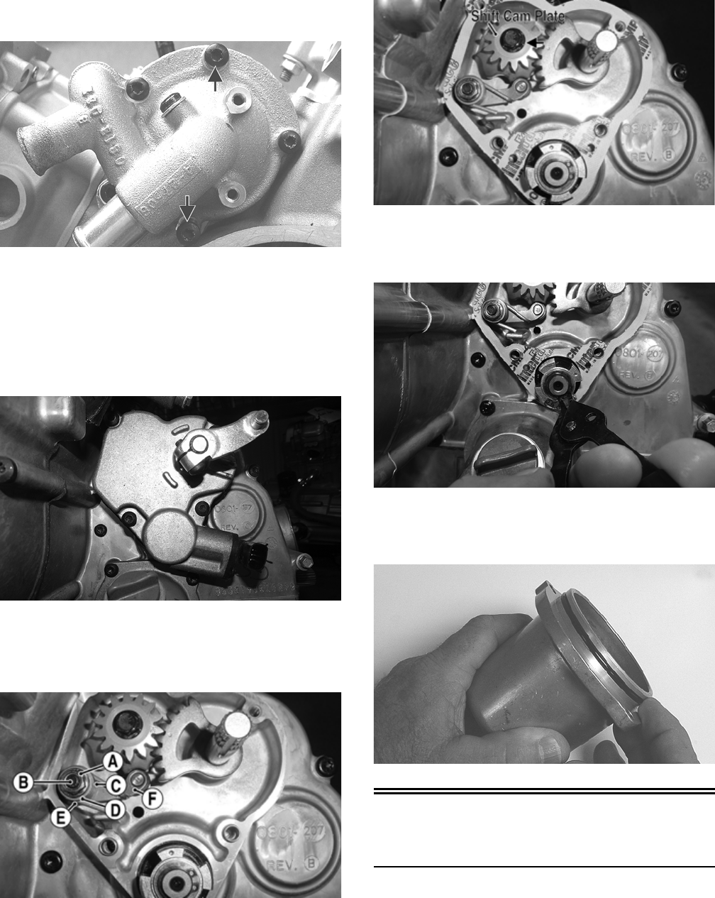
113
7. Remove the two cap screws securing the water pump
to the crankcase.
GZ230A
8. Remove the water pump. Account for an O-ring.
NOTE: The water pump is a non-serviceable compo-
nent and must be replaced as a complete assembly.
9. Remove the cap screws securing the speed sensor
housing to the crankcase; then remove the speed sen-
sor housing. Account for a gasket.
GZ524
10. Remove the nut (A) from the shift cam stopper sup-
port (B); then remove the cam stopper spring (C).
Account for a flat washer (D), cam stopper (F), and
shim (E).
H2-019C
11. Remove the cap screw securing the shift cam plate to
the shift cam shaft and remove the shift cam plate;
then remove the shift shaft.
H2-022A
12. Remove the snap ring securing the speed sensor trig-
ger to the shaft and remove the trigger using a suit-
able “two-jawed” puller. Account for a gasket.
H2-023
13. Remove the cap screws securing the oil filler cover
to the crankcase; then remove the cover. Account for
an O-ring.
GZ250
Servicing Left-Side
Components
INSPECTING STARTER
CLUTCH/GEAR
1. Place the starter clutch gear onto the rotor/flywheel and
attempt to rotate the starter clutch gear clockwise. It
should lock up to the rotor/flywheel. Rotate the gear
counterclockwise and it should turn freely. If it moves or
locks up both ways, the starter clutch must be replaced.
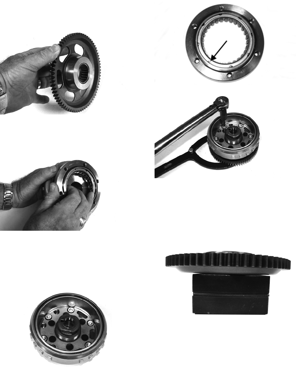
114
2. Inspect the starter clutch gear for chipped or missing
teeth or discoloration/scoring of the clutch surface.
Inspect the bearing for loose, worn, or discolored
rollers. If bearing is damaged, it must be replaced.
FI569
3. Inspect the one-way bearing for chipped surfaces,
missing rollers, or discoloration. If any of the above
conditions exist, replace the starter clutch assembly.
FI572
REPLACING STARTER CLUTCH
ASSEMBLY
1. Remove the cap screws securing the one-way clutch
assembly to the flywheel; then remove from the fly-
wheel.
FI570
2. Thoroughly clean the rotor/flywheel; then install the
new starter one-way clutch and secure with the cap
screws after applying a drop of red Loctite #271 to
the threads. Tighten to 26 ft-lb using a crisscross pat-
tern. Make sure the one-way bearing is installed with
the notches directed away from the rotor/flywheel.
FI576A
FI578
REPLACING STARTER GEAR
BEARING
1. Support the starter clutch gear in a press making sure
to support the hub around the entire circumference;
then using a suitable bearing driver, press the bearing
from the gear.
FI583
2. Thoroughly clean the gear hub; then apply a drop of
green Loctite #620 to the bearing outer race and
press into the gear hub until even with the lower
chamfer radius.
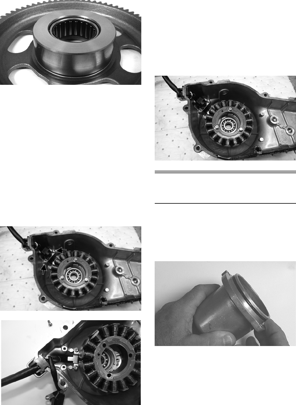
115
FI580
INSPECTING STATOR COIL/
MAGNETO COVER ASSEMBLY
1. Inspect the stator coil for burned or discolored wiring,
broken or missing hold-down clips, or loose cap screws.
2. Inspect the bearings in the magneto housing for dis-
coloration, roughness when rotated, and secure fit in
bearing bores.
REPLACING STATOR COIL/
CRANKSHAFT POSITION SENSOR
1. Remove the three cap screws securing the stator coil,
two cap screws securing the crankshaft position sen-
sor, and two cap screws from the harness hold-down.
2. Lift the rubber grommet out of the housing; then
remove the stator coil/crankshaft position sensor.
Account for and note the position of the harness
hold-down under the crankshaft position sensor.
H2-017A
H2-027
3. Install the new stator coil assembly and secure with
three cap screws using a drop of red Loctite #271 on
each. If installing the existing magneto cover, tighten
the cap screws to 11 ft-lb. If installing a new mag-
neto cover, tighten the cap screws to 13 ft-lb.
4. Place the stator wire harness hold-down into posi-
tion; then install the crankshaft position sensor and
secure with two cap screws. Tighten securely.
5. Install the upper cable hold-down and secure with
the cap screws. Tighten securely.
H2-017
Installing Left-Side
Components
1. Thoroughly clean all gasket material and sealant
from mating surfaces.
2. Install a new O-ring on the oil filler cover and coat it
with clean engine oil; then install the oil filler cover
into the crankcase and secure with the cap screws.
Tighten to 8 ft-lb.
GZ250
3. Clean the countershaft and trigger splines thoroughly
and install the inner snap ring onto the shaft; then
apply green Loctite #620 to the trigger and counter-
shaft splines and install the trigger. Secure with a flat
washer and outer snap ring.
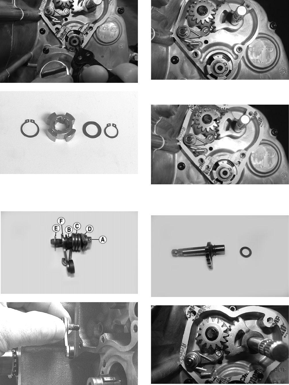
116
H2-023
GZ254
4. If removed, install the shim (E) and cam stopper (F);
then with the cam stopper support (B) in place,
install the spring (C), washer (D), and nut (A).
Tighten to 8 ft-lb.
FW-017B
GZ256
5. Install the shift cam stopper spring onto the shift cam
stopper and secure with a flat washer and nut.
Tighten to 8 ft-lb.
H2-019
6. Install the shift cam plate onto the shift cam shaft and
secure with the cap screw. Tighten to 8 ft-lb.
H2-022A
7. Install the shift shaft into the crankcase making sure
the washer is properly located; then align the timing
reference marks and completely seat the shift shaft.
FW-019
H2-026
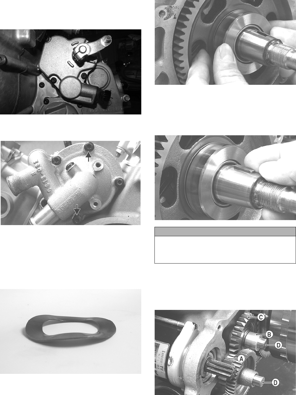
117
8. Apply grease to the lips of the shift shaft seal in the
speed sensor housing; then using a new gasket,
install the speed sensor housing and secure with the
cap screws. Tighten in a crisscross pattern to 8 ft-lb.
GZ524
9. With the O-ring properly positioned, install the water
pump. Secure using the two existing cap screws.
GZ230A
NOTE: The longer cap screw goes on the top of the
water pump.
10. Install the coolant hoses and secure with the hose
clamps.
11. Install the spacer washer on the crankshaft; then
install the starter ring gear.
GZ249
GZ226
12. Place the key into the keyway in the crankshaft; then
wipe all oil from the crankshaft surface and rotor/fly-
wheel bore and install the rotor/flywheel onto the
crankshaft aligning the keyway with the key. Secure
with the nut (coated with red Loctite #271) tightened
to 105 ft-lb.
GZ225
13. Install the starter driven and counter gear shafts (D)
into the crankcase (longer shaft to the front); then
install the starter countershaft gear (C), starter driven
gear (A), and bushing (B) making sure the cham-
fered gear teeth on the countershaft gear are directed
outward.
GZ224A
14. Install the starter motor with a new O-ring lightly
lubricated with grease; then tighten the mounting cap
screws to 8 ft-lb.
CAUTION
Make sure the one-way starter clutch is properly
engaged with the starter ring gear before installing and
tightening the rotor/flywheel nut or damage to the
clutch assembly could occur.
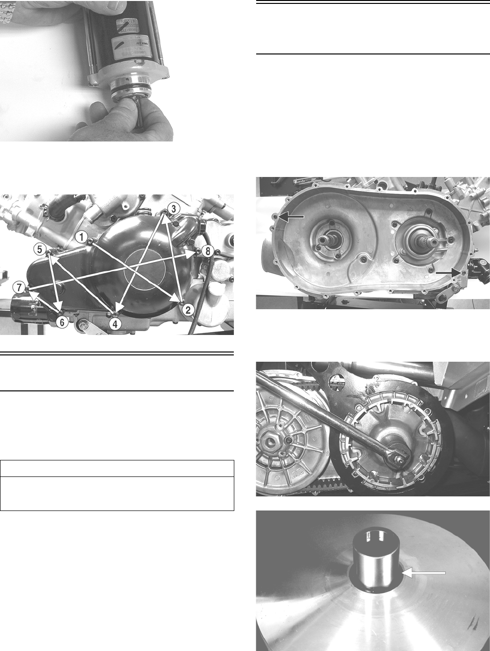
118
GZ251
15. Using Seal Protector Tool, install the outer magneto
cover using a new gasket and secure with the cap
screws. Using the pattern shown, tighten to 112 in.-lb.
GZ212B
Right-Side Components
NOTE: For efficiency, it is preferable to remove and
disassemble only those components which need to be
addressed and to service only those components. The
technician should use discretion and sound judgment.
NOTE: The engine/transmission does not have to
be removed from the frame for this procedure.
Removing Right-Side
Components
A. CVT Cover
B. Driven Clutch
C. Clutch Cover
D. Centrifugal Clutch
1. Remove the cap screws securing the CVT cover;
then using a rubber mallet, gently tap on the cover
tabs to loosen the cover. Account for a gasket and
two alignment pins.
GZ244B
2. Remove the nut securing the movable drive face;
then remove the face. Account for a spacer and a flat
washer.
GZ074
CD966A
3. Remove the V-belt.
AT THIS POINT
To service any one specific component, only limited dis-
assembly of components may be necessary. Note the
AT THIS POINT information in each sub-section.
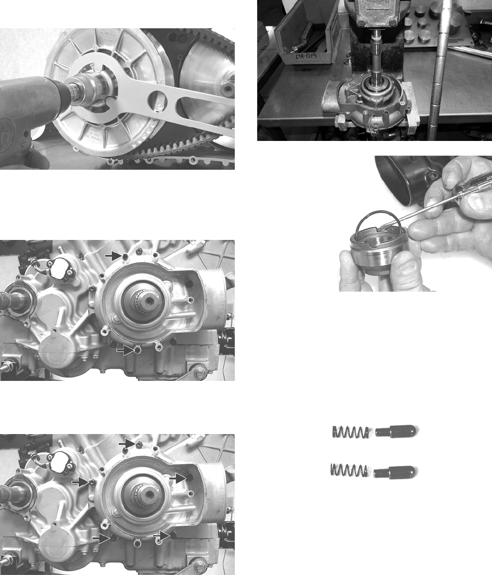
119
4. Remove the nut securing the fixed driven assembly;
then remove the assembly.
PR388
5. Remove the fixed drive face.
6. Remove the cap screws securing the V-belt housing
to the crankcase; then remove the V-belt housing.
Account for two alignment pins.
GZ246A
7. Remove the cap screws securing the clutch cover;
then using a rubber mallet, carefully remove the
cover. Account for two alignment pins.
GZ246B
8. Using a suitable press, remove the clutch housing
from clutch cover, account for fixed drive face
spacer and O-ring.
GZ511
CC596
NOTE: Account for and inspect the clutch housing
seal.
9. Remove the two cap screws securing the gear posi-
tion switch; then remove the switch. Account for two
contact pins with springs.
CD997
10. Remove and retain the two machine cap screws, and
bearing retainers.
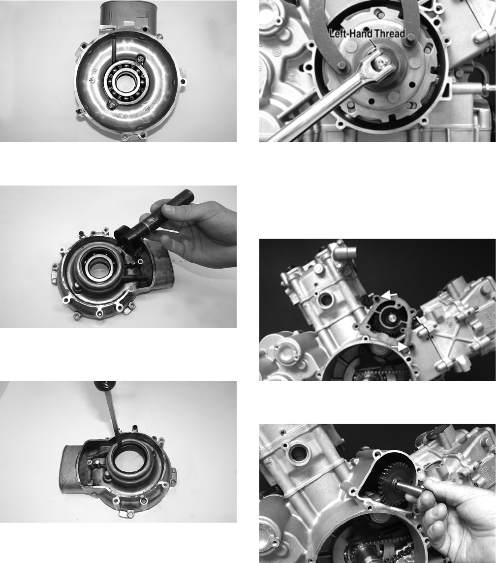
120
GZ500
11. Using a suitable press remove the bearing from the
clutch cover.
GZ507
12. Carefully remove the existing clutch housing seal
using caution not to damage the sealing surface of
the cover.
GZ513
13. Remove the one-way clutch from the centrifugal
clutch. Note the location of the green dot (or the
word OUTSIDE) for installing purposes.
14. Remove the nut (left-hand threads) securing the
clutch shoe assembly.
GZ438A
NOTE: Heating the nut will aid in removal.
15. Remove the two cap screws securing the gear posi-
tion switch; then remove the switch.
16. Remove the water pump drive housings. Account for
a gasket and two locator pins.
GZ437A
17. Remove the water pump drive shaft and gear assem-
bly from the engine.
GZ439
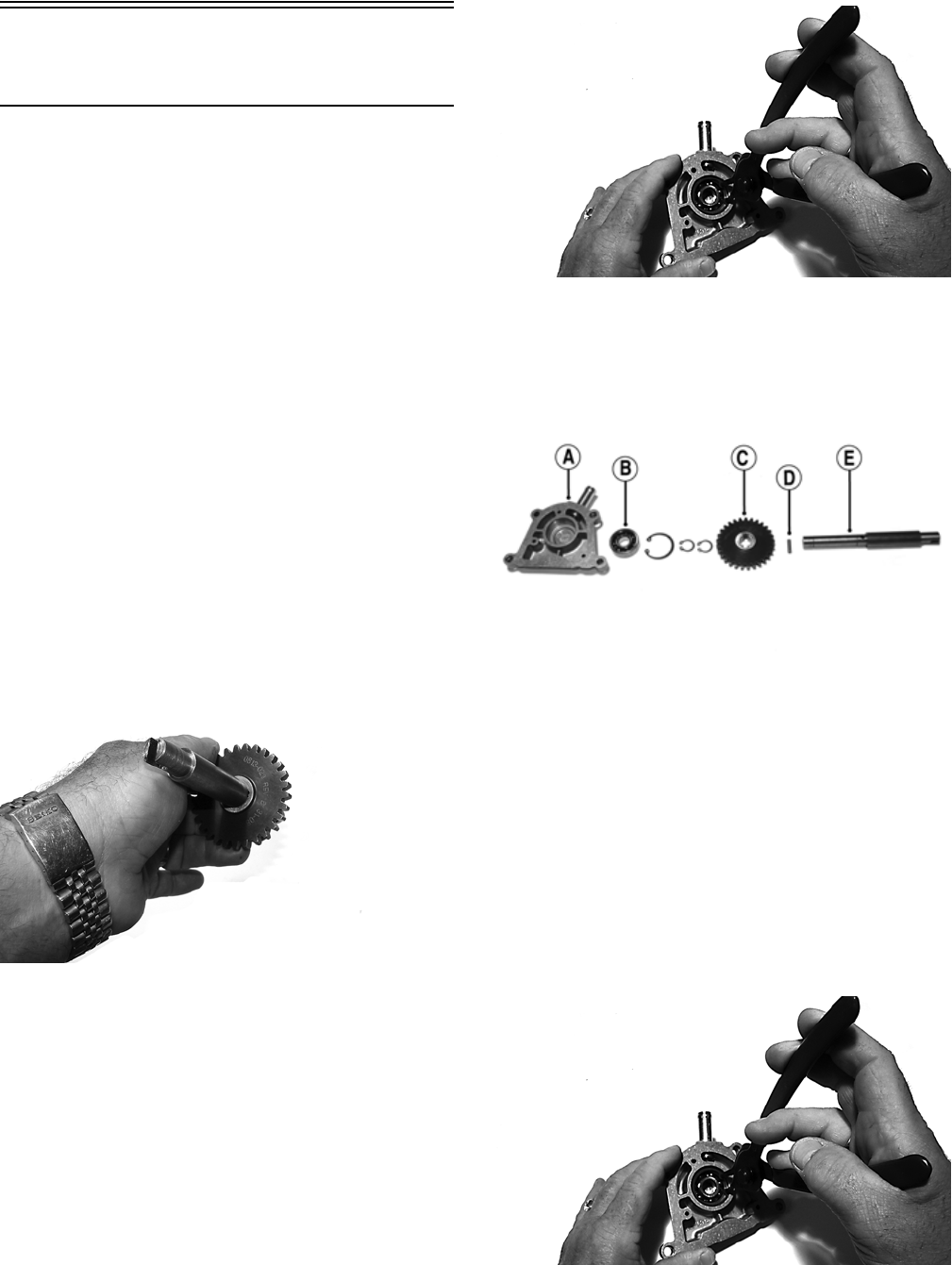
121
Servicing Right-Side
Components
INSPECTING CENTRIFUGAL
CLUTCH SHOES
1. Inspect the clutch shoes for wear, chips, cracks, dam-
age, or discoloration. If any shoe is damaged, replace
the centrifugal clutch.
INSPECTING CLUTCH HOUSING
1. Inspect the clutch housing for burns, grooving,
cracks, or uneven wear.
2. If the housing is damaged in any way, the housing
must be replaced.
DRIVEN CLUTCH ASSEMBLY
NOTE: The driven clutch is a non-serviceable com-
ponent. If the clutch faces, cam ramps, or face bush-
ing are worn or loose, the clutch must be replaced as
an assembly. Do not disassemble the driven clutch.
WATER PUMP DRIVE ASSEMBLY
Disassembling
1. Remove the two snap rings from the driveshaft; then
remove the gear and drive pin noting the orientation
of the gear for proper assembly.
GZ442
2. Remove the snap ring securing the bearing in the
water pump drive cover; then remove the bearing
using an appropriate blind bearing remover.
GZ441
Inspecting
1. Inspect the water pump drive housing (A) for scoring
or discoloration.
GZ440A
2. Inspect the bearing (B) for smooth rotation and no
discoloration or scoring.
3. Inspect the gear (C) for chipped or missing teeth,
excessive hub wear, or excessive wear in the drive
pin slot.
4. Inspect the drive pin (D) and driveshaft (E) for
excessive wear or looseness.
Assembling
1. Install the bearing in the water pump drive cover and
secure with the snap ring (flat side away from the
bearing).
GZ441
2. Install the gear onto the driveshaft noting correct ori-
entation (from step 1 of disassembling).
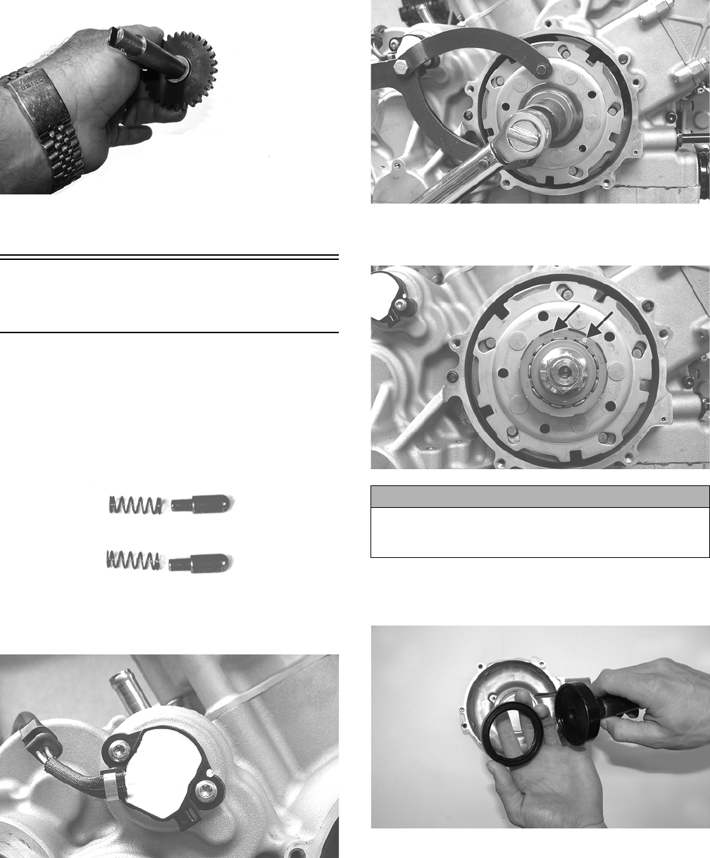
122
GZ442
3. Install the two snap rings on the driveshaft (flat side
away from the gear).
Installing Right-Side
Components
1. Apply silicone to the mating surfaces; then install the
gear position switch making sure the contact pins
and springs are properly positioned. Tighten the cap
screws securely.
CD997
GZ240
2. Install the clutch shoe assembly and secure with the
flange nut (threads coated with red Loctite #271).
Tighten to 221 ft-lb.
GZ241
3. Install the one-way clutch onto the clutch shoe
assembly.
GZ247B
4. Place a new clutch housing seal (with the spring side
facing the clutch housing seal tool) into the clutch
cover and secure with a rubber mallet or press.
GZ503
5. Using a suitable press, install the bearing into the
clutch cover against the outer bearing face.
CAUTION
Make sure the green dot (or the word OUTSIDE) is visi-
ble on the one-way clutch. Incorrect installation can
result in damage to the engine.

123
GZ501
NOTE: It is critical to verify the seal on the bearing
faces the clutch cover seal before pressing in the new
bearing.
6. Secure the bearing in the clutch cover using existing
bearing retainers and machine screws (threads coated
with blue Loctite #242). Tighten to 8 ft-lb.
GZ508
7. Press the clutch housing assembly into the clutch
cover until it is seated against the bearing.
GZ512
8. Install a new O-ring into a new fixed drive spacer,
then apply a thin coat of grease to the inner O-ring
and outside sealing surface of the drive spacer. Place
it over the clutch housing assembly.
ATV2109
9. Place the clutch cover/clutch housing assembly into
position on the crankcase; then secure with the cap
screws. Tighten in a crisscross pattern to 8 ft-lb.
GZ246B
10. Making sure the alignment pins are correctly installed,
place a bead of silicone sealant on the mating surfaces
and install the V-belt cover. Secure with new
“patch-lock” cap screws tightened to 8 ft-lb.
GZ263B
GZ244A
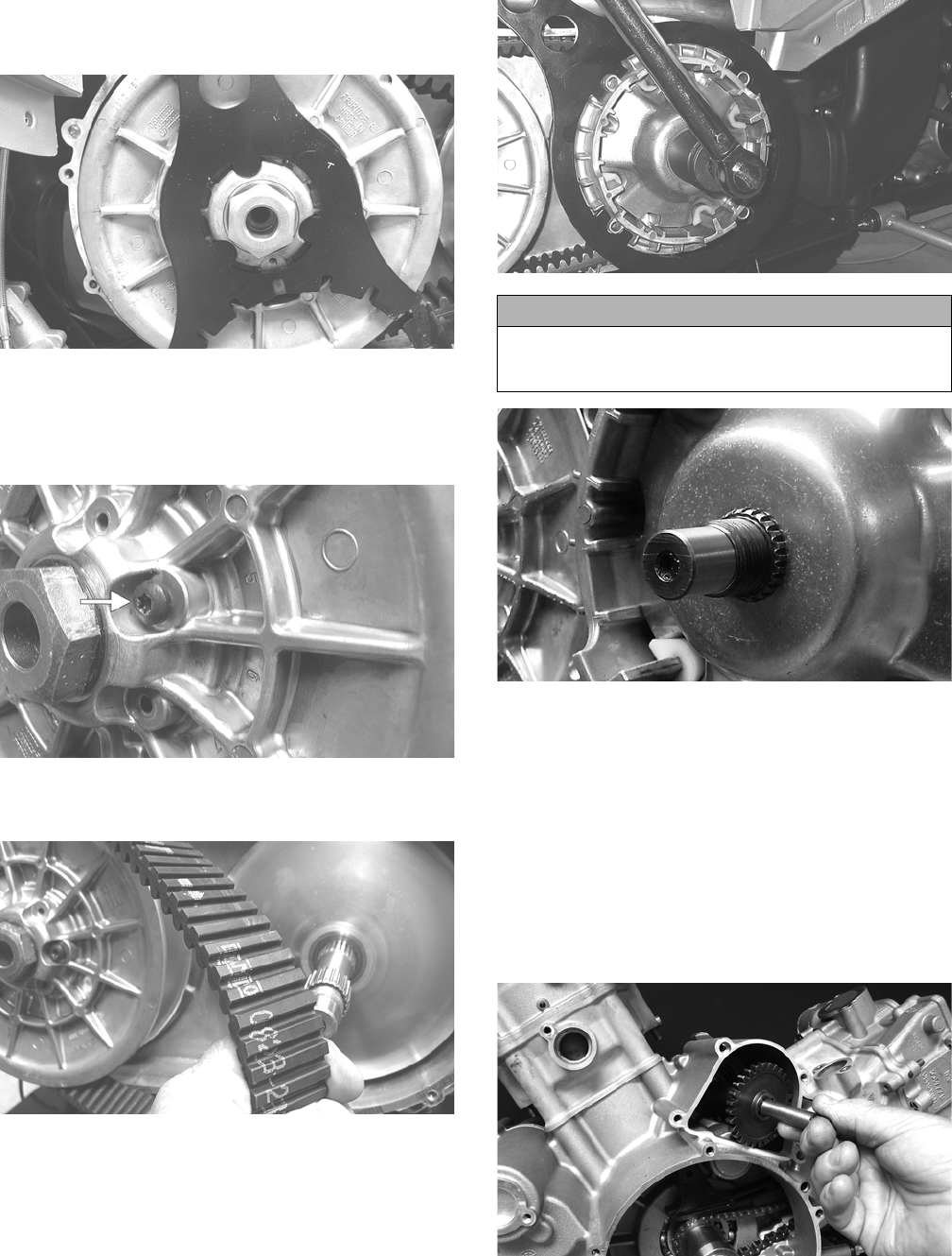
124
11. Place the driven clutch assembly into position and secure
with the nut (coated with red Loctite #271). Tighten to
165 ft-lb.
GZ066
12. Slide the fixed drive face onto the clutch shaft.
13. Spread the faces of the driven clutch by threading in a
cap screw; then when the faces are separated, insert the
belt and push down between the faces.
GZ065A
14. Place the V-belt into position on the driven clutch
and over the front shaft.
GZ085
NOTE: The arrows on the V-belt should point for-
ward.
15. Pinch the V-belt together near its center and slide the
spacer and movable drive face onto the shaft. Using
an appropriate spanner wrench, secure the drive face
with a flat washer and a nut (threads coated with red
Loctite #271). Tighten the nut to 165 ft-lb.
GZ075
GZ485
NOTE: At this point, the cap screw can be removed
from between the driven clutch faces.
16. With the engine in neutral, rotate the V-belt and
clutches counterclockwise until the V-belt is flush
with the top of the driven clutch.
17. Place the CVT cover gasket into position; then install
the cover and secure with the cap screws. Tighten the
cap screws to 8 ft-lb.
18. Install the water pump drive shaft/gear assembly into
the engine.
GZ439
19. Install the two locating pins and a new gasket on the
engine; then install the water pump drive housing
cover and tighten the cap screws to 8 ft-lb.
CAUTION
Make sure the splines extend beyond the drive face and
washer or a false torque reading and spline damage
may occur.
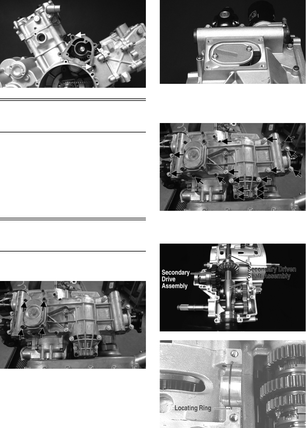
125
GZ437A
Center Crankcase
Components
NOTE: This procedure cannot be done with the
engine/transmission in the frame. Complete Remov-
ing procedures for Top-Side, Left-Side, and
Right-Side must precede this procedure.
NOTE: For efficiency, it is preferable to remove and
disassemble only those components which need to
be addressed and to service only those components.
The technician should use discretion and sound
judgment.
Separating Crankcase
Halves
1. Remove the oil strainer cap; then remove the oil
strainer.
H2-012A
GZ446
2. Remove the cap screws securing the lower crankcase
to the upper crankcase halves; then using a rubber
hammer, free the lower crankcase and remove.
Account for two alignment pins.
H2-012B
3. Remove the secondary drive assembly; then remove
the secondary driven shaft assembly and set aside.
Account for one locating ring.
GZ448A
GZ269A
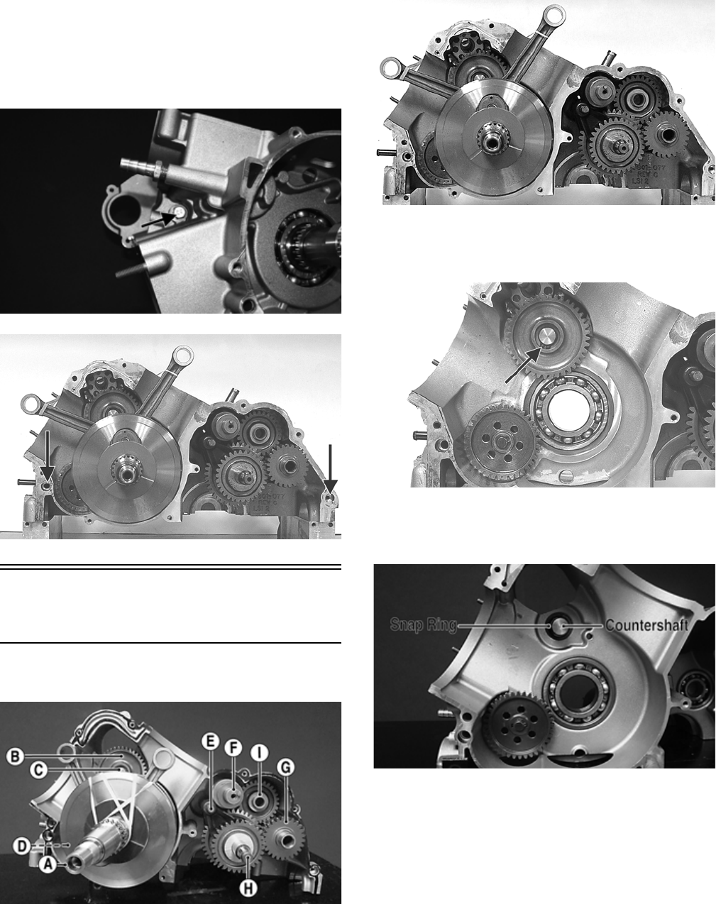
126
NOTE: Do not disassemble these assemblies
unless service is required. If disassembled, second-
ary gear sets will have to be reset for backlash and
gear contact (see Servicing Center Crankcase Com-
ponents sub-section).
4. Remove one cap screw from the right-side crankcase
and eight cap screws from the left-side crankcase; then
using a rubber mallet, separate the crankcase halves
leaving all components in the right-side case. Account
for a thrust washer on the crankshaft and flat washers
on gear shift shaft, countershaft, and reverse idler. Note
the location of two alignment pins.
GZ454A
GZ272B
Disassembling Crankcase
Half
NOTE: For steps 1-8, refer to illustration GZ474A.
GZ474A
NOTE: To aid in installing, it is recommended the
assemblies are kept together and IN ORDER.
1. Support the right-side crankcase assembly on suit-
able support blocks; then carefully remove the crank-
shaft assembly (A) from the crankcase.
GZ298
2. Remove the snap ring securing the water pump drive
idler (B) to the idler shaft; then remove the drive
idler.
GZ299A
3. Remove the snap ring securing the water pump idler
shaft (C) in the crankcase; then remove the shaft and
bearings.
GZ463A
4. Remove the snap ring securing the oil pump driven
gear (D) to the oil pump driveshaft; then remove the
gear. Account for a drive pin and washer.
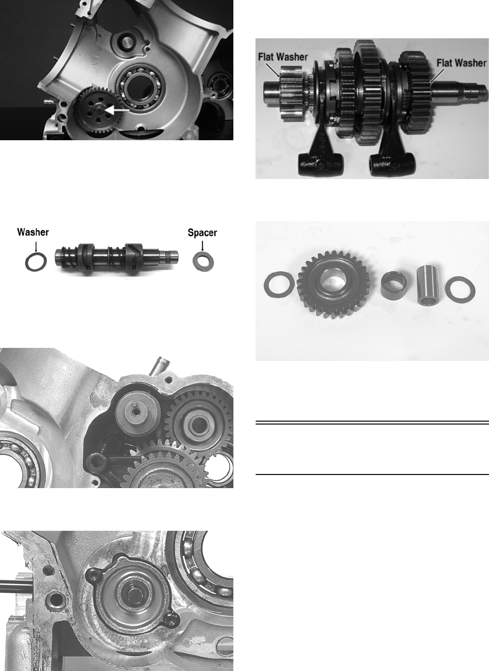
127
GZ463B
5. Remove the shift fork shaft (E); then remove the gear
shift shaft assembly (F). Account for a flat washer
and a spacer.
DE677A
GZ276
6. Remove two cap screws securing the oil pump in the
crankcase and remove the oil pump.
GZ305
7. Remove the driveshaft (G); then remove the counter-
shaft assembly (with shift forks) (H). Account for
two flat washers on the countershaft.
GZ280B
8. Remove the reverse idler gear (I), shaft bushing, and
two washers.
GZ279
NOTE: Do not disassemble the countershaft assem-
bly unless necessary. If necessary, see Servicing
Center Crankcase Components sub-section.
Servicing Center
Crankcase Components
SECONDARY OUTPUT DRIVE
GEARS
Initial Set-Up
NOTE: If the secondary output driven shaft is
replaced or disassembled, the initial set-up must be
performed to establish correct gear tooth contact. If
only the secondary output driveshaft or secondary
output driven gear are replaced, proceed to Correct-
ing Backlash in this sub-section.
1. Install a new bearing (A) onto the secondary driven
shaft (B) making sure the bearing locating groove is
directed away from the driven gear splines.
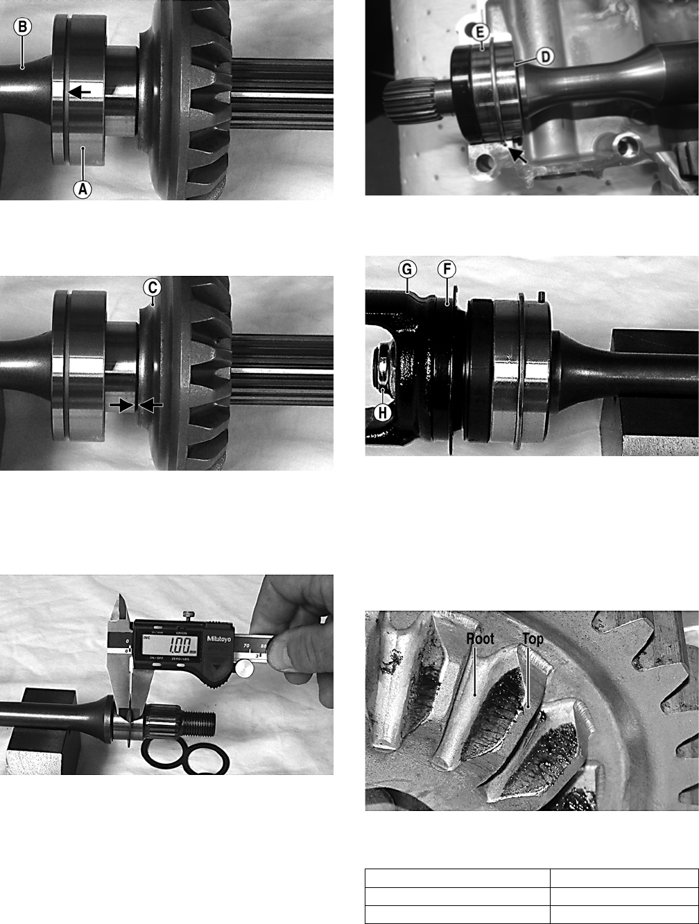
128
MT011A
2. Using a suitable press, install the driven gear (C) on
the shaft until the gear firmly seats on the shoulder of
the shaft.
MT011B
3. If installing the existing shaft, start with the shims
removed during disassembly or if installing a new shaft,
start with approximately 1.0 mm shims at point (D); then
install the output driveshaft bearing (E) making sure the
locating pin is directed toward the center of the shaft.
MT012
FW-003A
4. Install a new seal (F), output yoke (G), washer, and nut
(H) and tighten to 200 ft-lb.
MT008B
NOTE: Do not use a new lock nut at this time as this
procedure may have to be repeated.
5. Place the assembled shaft into the left crankshaft
case; then lightly coat the gear teeth with machinist’s
lay-out dye. Rotate the shafts through several rota-
tions in both directions. Gear contact should extend
from the root to the top of the gear teeth.
MT016A
6. To adjust tooth contact, use the following chart to
correctly shim the driven shaft.
7. After correct tooth contact is established, proceed to
Checking Backlash in this sub-section.
Tooth Contact Shim Correction
Contact at Top Increase Shim Thickness
Contact at Root Decrease Shim Thickness
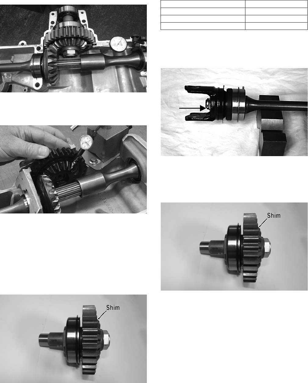
129
Checking Backlash
1. Install the drive bevel gear assembly and driven
bevel gear/output shaft assembly into the crankcase
bottom cover.
2. Mount the dial indicator so the tip is contacting a
tooth on the secondary drive bevel gear.
FW-008
3. Firmly hold the bearing down and while rocking the
drive bevel gear back and forth, note the maximum
backlash reading on the gauge.
GZ398
4. Acceptable backlash range is 0.127-0.381 mm
(0.005-0.015 in.).
Correcting Backlash
NOTE: If backlash measurement is within the
acceptable range, no correction is necessary.
1. If backlash measurement is less than specified,
remove an existing shim, measure it, and install a
new thinner shim.
FW-006A
2. If backlash measurement is more than specified,
remove an existing shim, measure it, and install a
thicker shim.
NOTE: Continue to remove, measure, and install
until backlash measurement is within tolerance. Note
the following chart.
3. Once correct gear pattern and backlash are estab-
lished, install a new lock nut (coated with red Loctite
#271) on the output yoke and tighten to 200 ft-lb.
Peen the lock nut to the shaft.
MT007A
4. Using an appropriate holding fixture and wrench
adapter, install the secondary drive gear nut (threads
coated with red Loctite #271) and tighten to 200
ft-lb. The output drive assembly is now ready for
installation.
FW-006A
OIL PUMP ASSEMBLY
Disassembling and Inspecting
1. Remove the oil pump cover; then remove the gerotor
set, shaft, and pin (see Disassembling Crankcase
Half in this sub-section).
2. Inspect the crankcase for scoring, discoloration, or
cracks in the gerotor bore. If scored, crankcase
assembly must be replaced.
Backlash Measurement Shim Correction
Under 0.127 mm (0.005 in.) Decrease Shim Thickness
At 0.127-0.381 mm (0.005-0.015 in.) No Correction Required
Over 0.381 mm (0.015 in.) Increase Shim Thickness
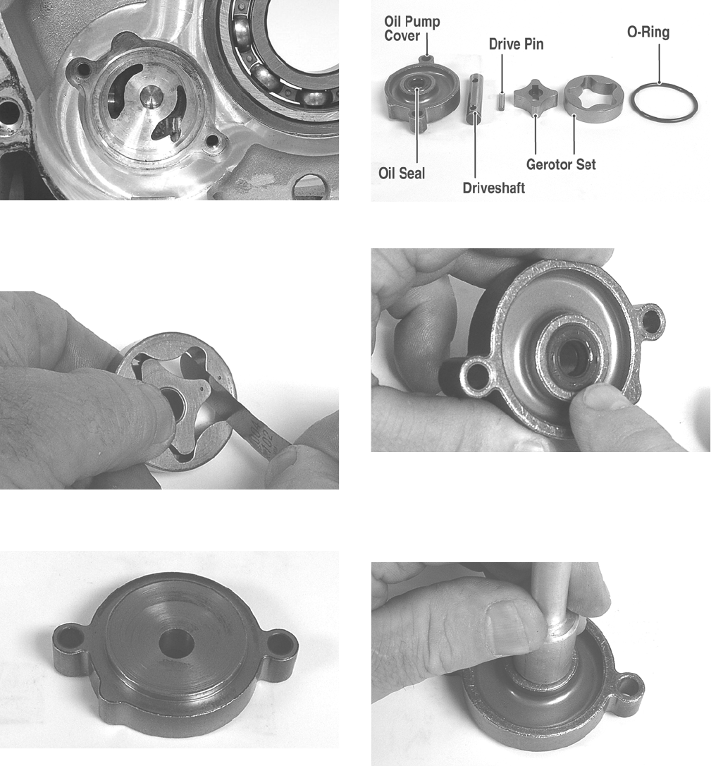
130
GZ357
3. Inspect the gerotor set for scoring, discoloration, or
cracks; then using a feeler gauge, check the inner to outer
rotor clearance. If measurements exceed specifications,
the gerotor set must be replaced.
GZ355
4. Inspect the oil pump cover for scoring, discoloration, or
cracks. Replace if damaged.
GZ358
5. Inspect the oil pump driveshaft and drive pin for exces-
sive wear or grooving. Replace as required.
GZ354A
6. Remove the oil seal from the oil pump cover.
GZ365
Assembling
1. Install a new oil seal into the oil pump cover; then
coat the lips of the seal with grease and install the
pump driveshaft from the seal side.
GZ359
2. Noting the reference dots on the gerotor set, separate
the inner rotor from the outer rotor and with the ref-
erence dot directed toward the oil pump cover, place
the rotor on the shaft; then install the drive pin and
push the shaft into the rotor.
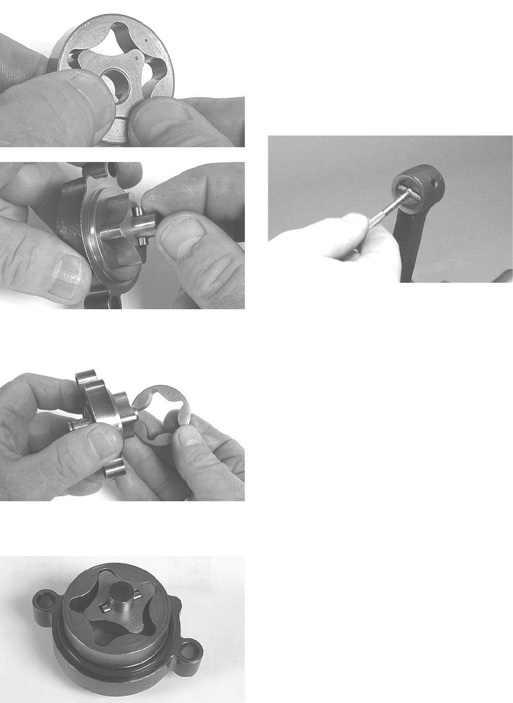
131
GZ356
GZ363
3. With the outer rotor reference dot directed toward the
oil pump cover, install the rotor onto the inner rotor.
GZ360
4. Place a new O-ring seal on the outside of the oil
pump cover. The oil pump assembly is now ready for
assembly into the crankcase.
GZ362
CRANKSHAFT ASSEMBLY
NOTE: The crankshaft and connecting rod is a
non-serviceable assembly. If any component is out of
specification, the assembly must be replaced.
Measuring Connecting Rod
(Small End Inside Diameter)
1. Insert a snap gauge into the upper connecting rod
small end bore; then remove the gauge and measure
it with micrometer.
CC290D
2. Maximum diameter must not exceed specifications.
Measuring Connecting Rod
(Small End Deflection)
1. Place the crankshaft on a set of V blocks and mount a
dial indicator and base on the surface plate. Position
the indicator contact point against the center of the
connecting rod small end journal.
2. Zero the indicator and push the small end of the con-
necting rod away from the dial indicator.
3. Maximum deflection must not exceed specifications.
Measuring Connecting Rod
(Big End Side-to-Side)
1. Push the lower end of the connecting rod to one side
of the crankshaft journal.
2. Using a feeler gauge, measure the gap between the
connecting rod and crankshaft journal.
3. Acceptable gap range must be within specifications.
Measuring Crankshaft (Runout)
1. Place the crankshaft on a set of V blocks.
2. Mount a dial indicator and base on the surface plate.
Position the indicator contact at point 1 of the crank-
shaft.
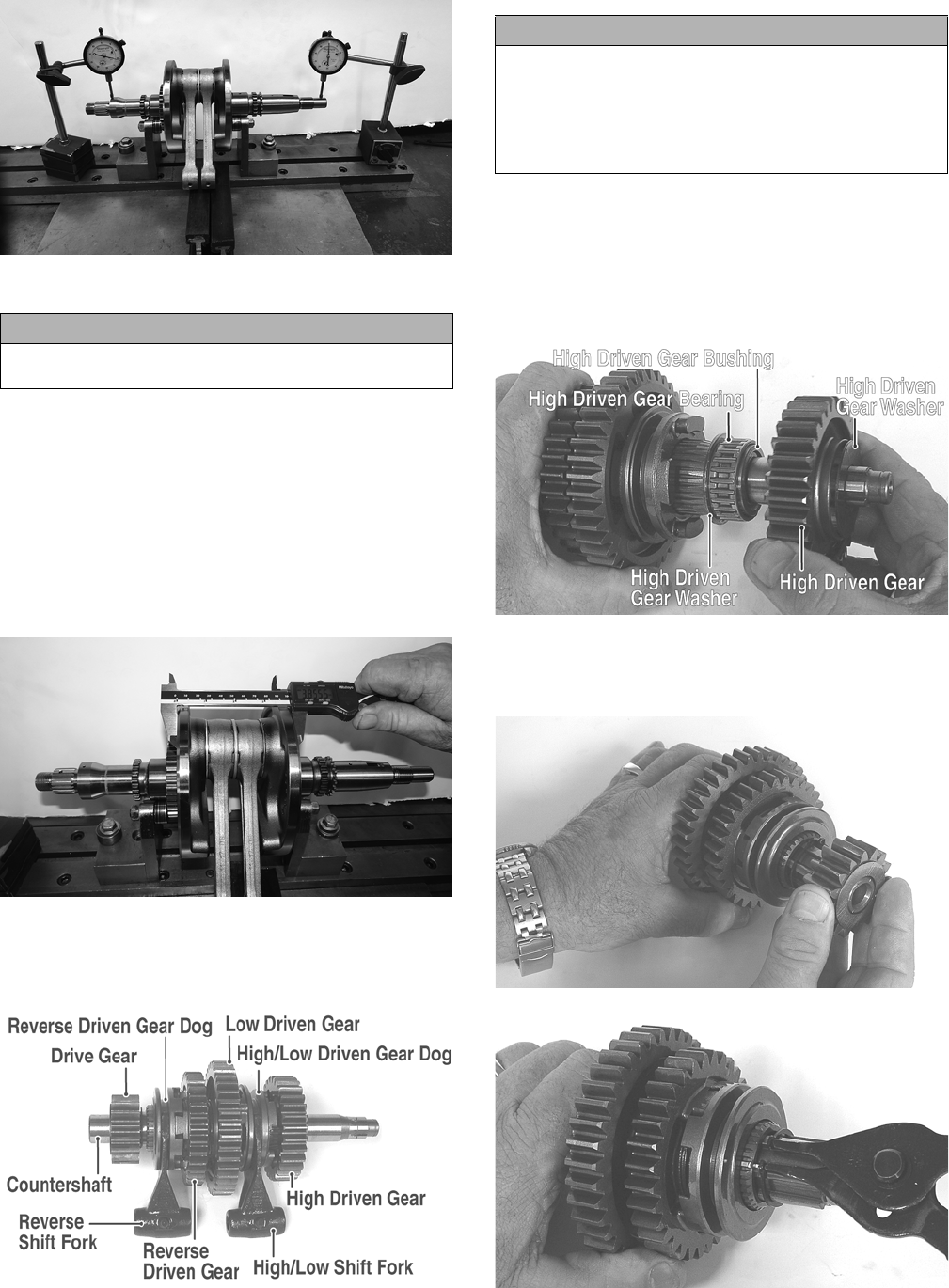
132
H2-004
3. Zero the indicator and rotate the crankshaft slowly.
4. Maximum runout must not exceed specifications.
NOTE: Proceed to check runout on the other end of
the crankshaft by positioning the indicator contact at
point 2 and following steps 3-4.
Measuring Crankshaft
(Web-to-Web)
1. Using a calipers, measure the distance from the outside
edge of one web to the outside edge of the other web.
H2-005
2. Acceptable width range must be within specifica-
tions.
COUNTERSHAFT
GZ281A
Disassembling
1. Remove the shift forks noting the positions for
assembling; then remove the high driven gear outer
washer, high driven gear, high driven gear bearing,
high driven gear bushing, and high driven gear inner
washer.
GZ283A
2. Remove the drive gear; then remove the snap ring
securing the reverse driven gear dog and bushing to
the countershaft.
GZ296
GZ312
3. Remove the reverse driven gear dog.
CAUTION
Care should be taken to support the connecting rod
when rotating the crankshaft.
CAUTION
When disassembling the countershaft, care must be
taken to note the direction each major component (dog,
gear) faces. If a major component is installed facing the
wrong direction, transmission damage may occur
and/or the transmission will malfunction. In either case,
complete disassembly and assembly will be required.
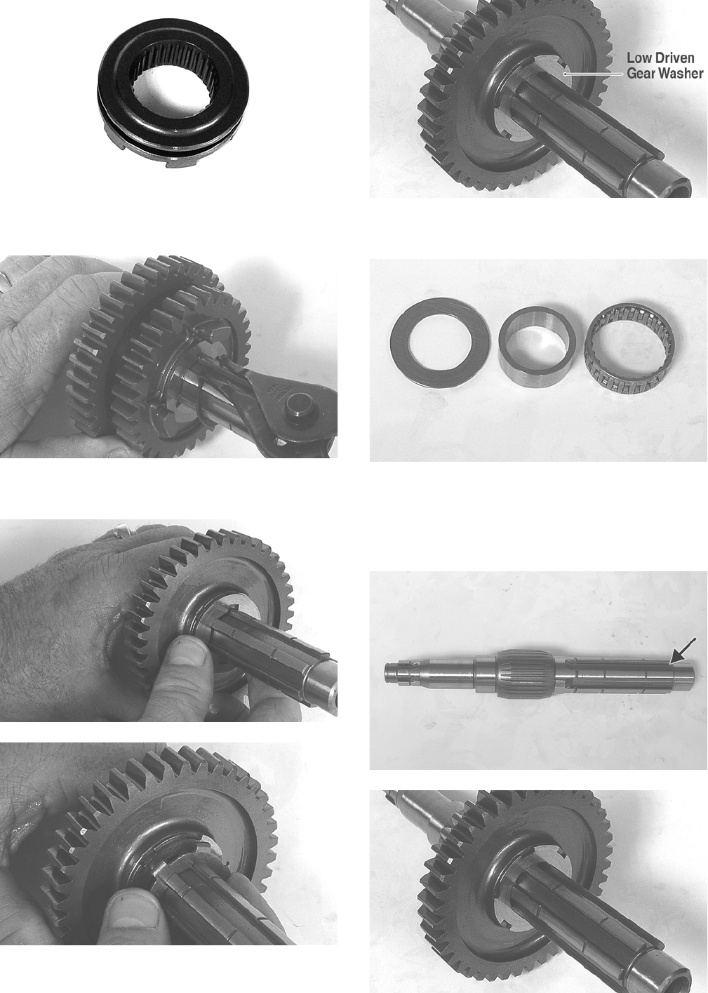
133
GZ313A
4. Remove the snap ring securing the reverse driven
gear and washer; then remove the washer and gear.
GZ314
5. Remove the reverse driven washer; then remove the
low driven gear locking washer.
GZ320
GZ319
GZ318A
6. Remove the low driven gear. Account for a bearing,
bushing, and thrust washer.
GZ316
Assembling
1. From the drive gear end, install a thrust washer,
bushing, and bearing; then install the low driven gear
and washer.
GZ317A
GZ318
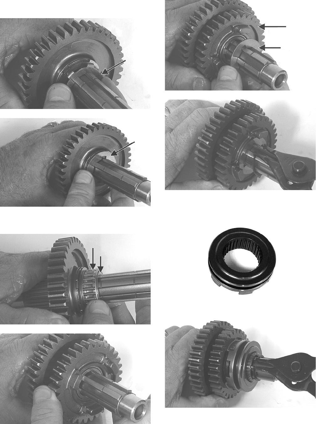
134
2. Install the low driven gear locking washer; then
install the inner reverse driven gear washer.
GZ319B
GZ320B
3. Install the reverse driven bushing and bearing; then
install the reverse driven gear.
GZ286A
GZ287
4. Install the outer reverse driven washer; then secure
the reverse driven gear assembly with a snap ring.
GZ288A
GZ314
5. Install the reverse driven gear dog onto the counter-
shaft and secure with a snap ring.
GZ313A
GZ312
6. From the opposite end of the countershaft, install the
high/low driven gear dog (A), thrust washer (B),
bushing (C), bearing (D), high/low driven gear (E),
and spacer washer (F).
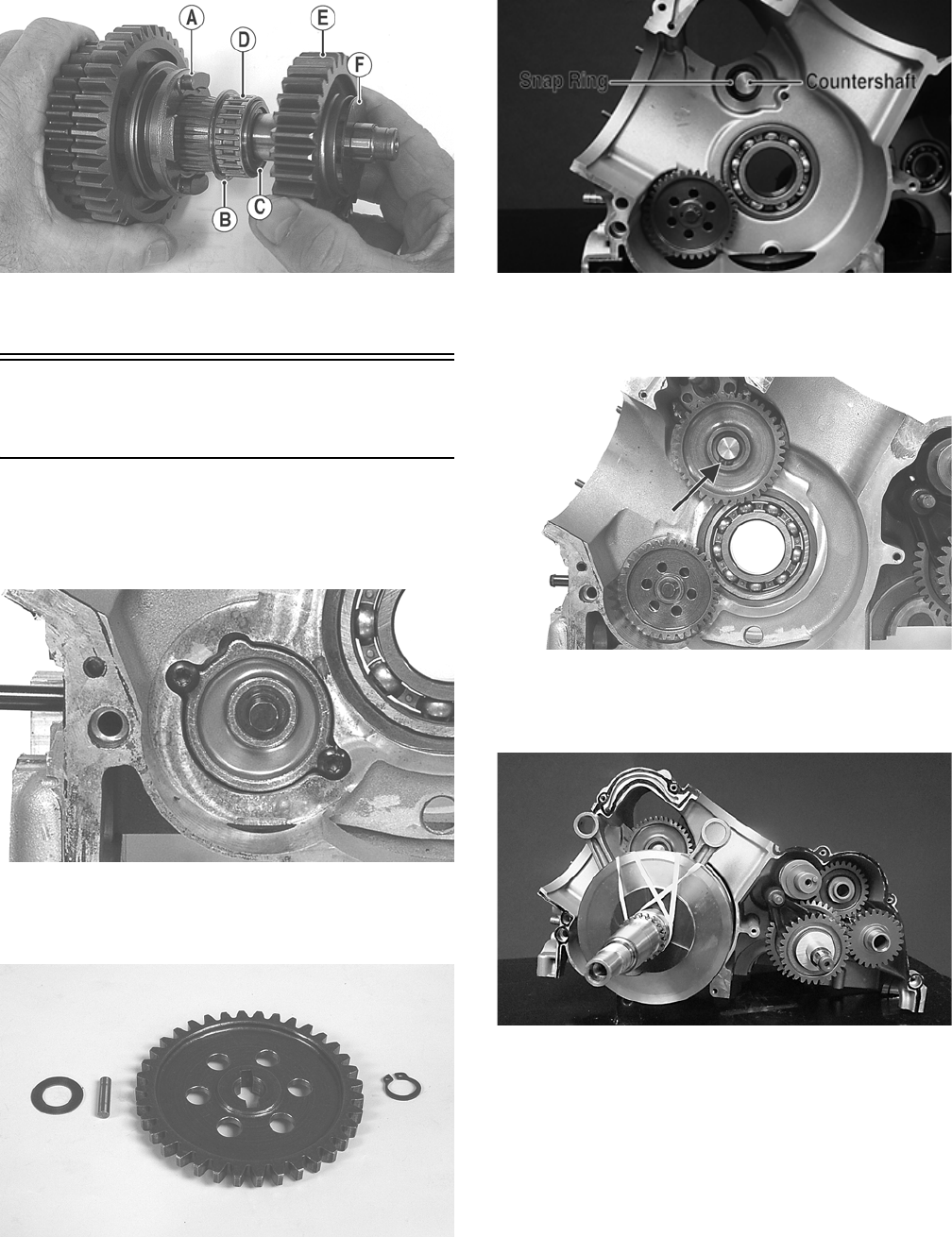
135
GZ283B
7. Install the drive gear washer and the shift forks. The
countershaft is now ready for installation.
Assembling Crankcase
Half
1. Install the oil pump gerotor assembly and oil pump
cover into the crankcase and secure with two cap
screws. Coat the threads with blue Loctite #243 and
tighten securely to 8 ft-lb.
GZ305
2. Install a flat washer, drive pin, and drive gear onto
the oil pump shaft; then secure with a snap ring
(flat-side away from the gear).
GZ347
3. Install the countershaft into the crankcase and secure
with the snap ring (flat side away from the bearing).
GZ463A
4. Install the countershaft gear onto the countershaft
and secure with a snap ring (flat-side away from the
gear).
GZ299A
5. Using rubber bands to support the connecting rods,
carefully install the crankshaft assembly into the
crankcase.
GZ474
NOTE: It will be necessary to rotate the crankshaft
back and forth to engage the teeth of the oil pump
and countershaft gears.
6. Install the driveshaft; then with a flat washer on each
end of the reverse idler assembly, install into the
crankcase.
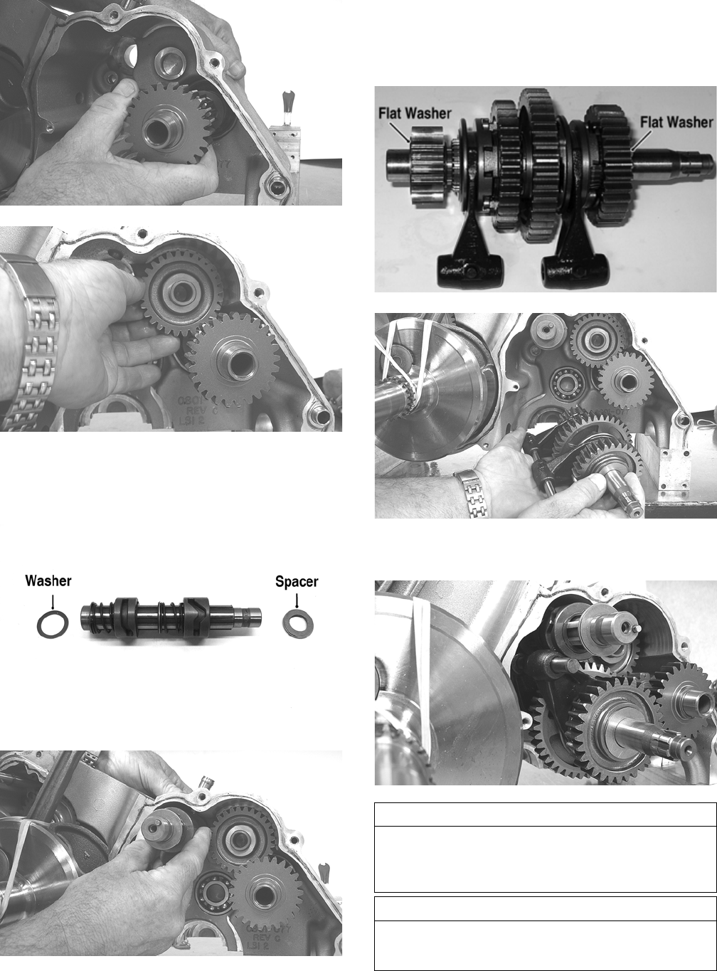
136
GZ332
GZ333
7. Install the gear shift shaft into the crankcase making
sure the flat washer is in place on the right case end
and the spacer bearing assembly on the gear shift
stop end.
DE677A
GZ335
8. Place the larger flat washer on the drive gear end of
the countershaft and the smaller flat washer on the
high driven gear end; then with shift forks and shift
fork shaft, install the countershaft assembly into the
crankcase.
GZ280B
GZ336
9. Engage the shift forks into the gear shift shaft and
push the shift fork shaft into the crankcase.
GZ339
AT THIS POINT
Proper transmission shifting should be verified by turn-
ing the gear shift shaft to select High, Low, Neutral, and
Reverse while rotating the input shaft and observing the
countershaft rotation.
AT THIS POINT
The right-side crankcase is now ready for installation to
the left-side crankcase. Proceed to Joining Crankcase
Halves.

137
Joining Crankcase Halves
1. Using rubber bands, support the connecting rods to
align with the cylinder bores.
GZ340
2. Coat both sides with engine oil; then install the
spacer washer on the crankshaft with the radius
directed toward the crankshaft.
GZ341
3. Install the two alignment pins; then apply a thin bead
of Loctite #5900 or suitable substitute sealant to the
crankcase mating surface.
NOTE: Apply sealant sparingly in areas depicted by
arrows.
GZ298B
4. Carefully join the crankcase halves by placing the
left-side crankcase onto the assembled right side.
Secure with the cap screws (eight left side and one
right side).
GZ342
5. Tighten the 6 mm cap screws to 10 ft-lb and the 8
mm cap screws to 21 ft-lb using the pattern shown
and turning the shafts frequently to ensure there is no
binding.
NOTE: Rotate the shafts back and forth to ensure
no binding or sticking occurs.
GZ457A
NOTE: Cap screw number eight (8) is installed from
the right side.
NOTE: If the secondary drive/driven assemblies
have been disassembled, refer to Servicing Center
Crankcase Components for proper gear tooth contact
and backlash.
6. Install the locating ring in the crankcase assembly;
then install the secondary driven shaft assembly and
secondary drive assembly making sure the locating
ring and bearing engage correctly.
GZ269A
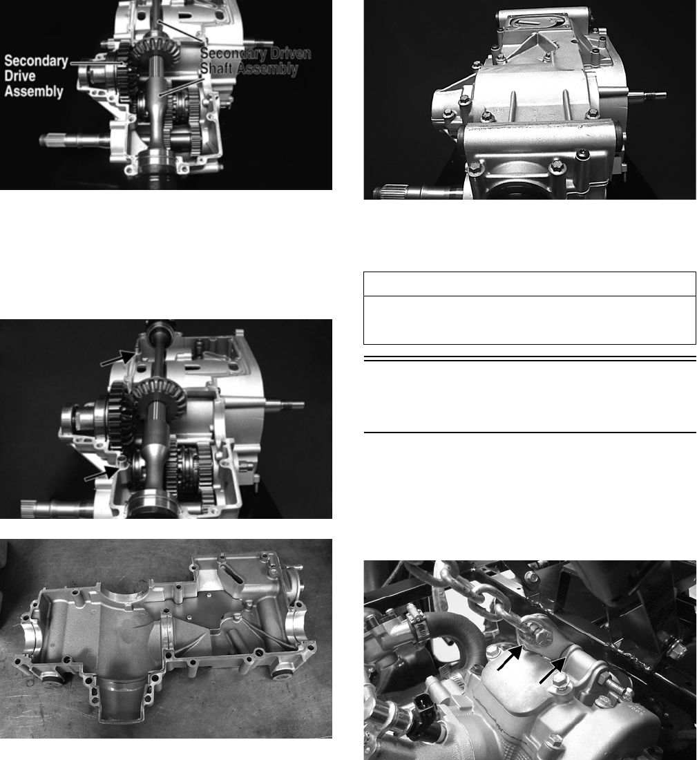
138
GZ448A
7. Make sure the locating pins on the front and rear
bearings are correctly seated in the crankcase.
8. Install two alignment pins into the upper crankcase
assembly; then apply a thin bead of Loctite #5900 or
suitable substitute sealant to the lower crankcase
cover.
GZ452A
GZ451
9. Carefully place the lower crankcase cover onto the
joined crankcase halves; then secure with the cap screws.
Tighten the 6 mm cap screws to 10 ft-lb and the 8 mm
cap screws to 21 ft-lb.
GZ447
10. Install the oil strainer; then apply a thin bead of silicone
sealant to the oil strainer cap and secure with the cap
screws. Tighten to 8 ft-lb.
Installing
Engine/Transmission
NOTE: Arctic Cat recommends new gaskets and
O-rings be installed whenever servicing the vehicle.
1. Attach a suitable lifting chain to the engine; then using
an engine hoist, lift the engine/transmission into the
vehicle from the right side.
PR632A
AT THIS POINT
After completing center crankcase components, proceed to
Installing Right-Side Components, to Installing Left-Side
Components, and to Installing Top-Side Components.
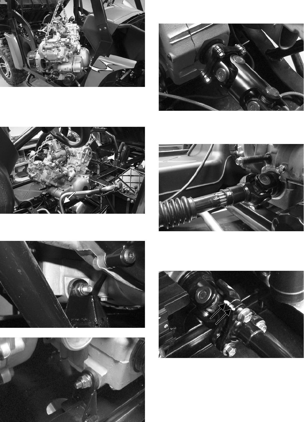
139
PR633
2. Carefully lower the engine/transmission into position
between the engine mounting tabs being careful to
keep all cables, wires, and hoses clear; then install
the longer, front through-bolt with a flat washer.
PR634A
3. Install the rear through-bolts with flat washer; then
secure both with new lock nuts and tighten to 40 ft-lb.
PR629
PR630
4. Secure the rear universal joint flange to the output
drive flange and tighten the four cap screws to 40
ft-lb.
PR647
5. Lubricate the splines on the front driveshaft with
multi-purpose grease; then align the match marks
and install the driveshaft into the front output joint.
PR639
6. Align the match mark on the front drive flange to
mark on the front universal joint flange and secure
with three cap screws. Tighten to 40 ft-lb and slide
the rubber boot back into position.
PR638A
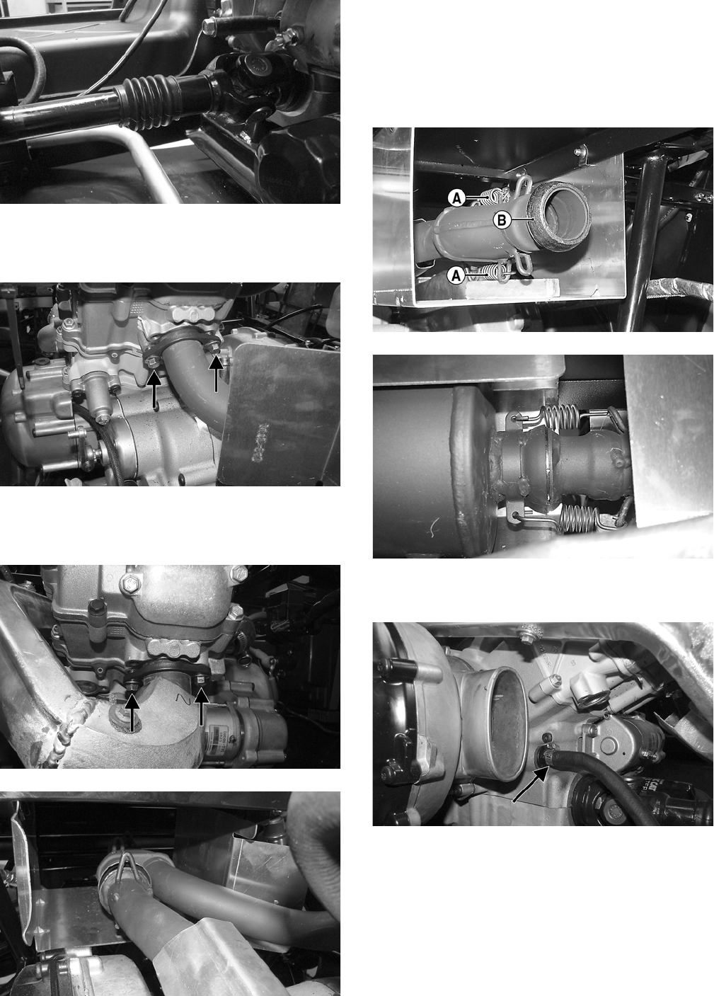
140
PR640
7. Install a new grafoil gasket in the rear cylinder head;
then place the rear exhaust pipe into position and
loosely secure with two cap screws.
PR641A
8. With a new grafoil gasket in the front cylinder head and
a new grafoil seal on the exhaust pipe, install the front
exhaust pipe and loosely secure with two cap screws.
PR643A
PR642
9. Install the O2 sensor and tighten the sensor to 19
ft-lb. Connect the harness to the sensor.
10. Install the two springs (A) at the juncture of front and
rear exhaust pipes. With a new grafoil seal (B) in
place, install the muffler and secure with two
springs; then tighten the cap screws from steps 7 and
8 to 20 ft-lb.
PR661C
PR668
11. Connect the oil cooler hoses to the engine and secure
with the hose clamps. Tighten securely.
PR616A
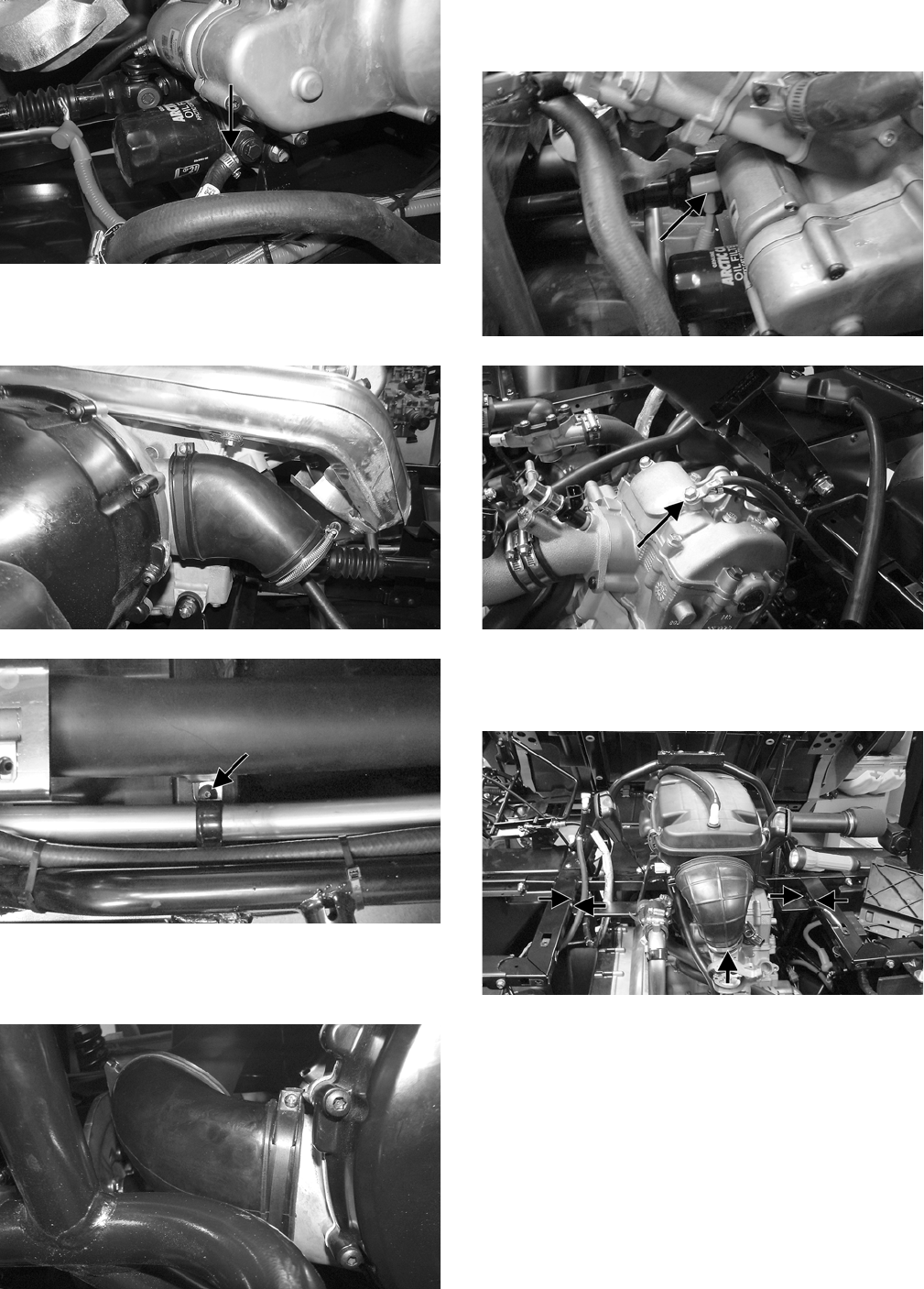
141
PR617A
12. Install the inlet boot on the CVT cover; then install the
CVT cooling duct and secure with the sheet metal screw.
Tighten all fasteners and clamps securely.
PR615
PR671A
13. Install and secure the CVT cooling outlet boot to the
CVT cover making sure to properly orient the outlet
duct.
PR669
14. Connect the starter cable to the starter; then connect the
engine harness ground to the engine. Tighten the fasten-
ers securely.
PR605A
PR604A
15. Install the air filter assembly and secure with four sheet
metal screws; then secure the intake boot to the throttle
body. Tighten the screws and clamp to 30 in.-lb.
PR603A
16. Connect the gasline hoses to the fuel rails making sure
the “quick-disconnect” couplers properly lock onto the
fuel injector rails.
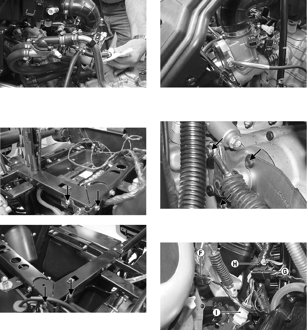
142
PR663
17. Install the shift support assembly and secure with four
cap screws; then secure the upper coolant pipe support
clamp to the shift support. Tighten the cap screws
securely.
PR596A
PR598A
18. Connect the throttle cable to the throttle arm; then
install the cable housing into the throttle body hous-
ing and tighten the nuts securely.
19. Adjust throttle cable free-play; then install the throt-
tle cable cover.
PR666
20. Install the shift cable support bracket and secure with
two cap screws; then tighten to 8 ft-lb and install the
E-clip securing the shift cable to the shift arm.
PR662A
21. From the left side, connect the speed sensor connec-
tor (F), stator coil connector (G), CKP sensor (H),
and gear position switch connector (I).
PR658A
22. Route the engine harness through the shifter support
brackets as marked during disassembly and secure
with nylon cable ties.
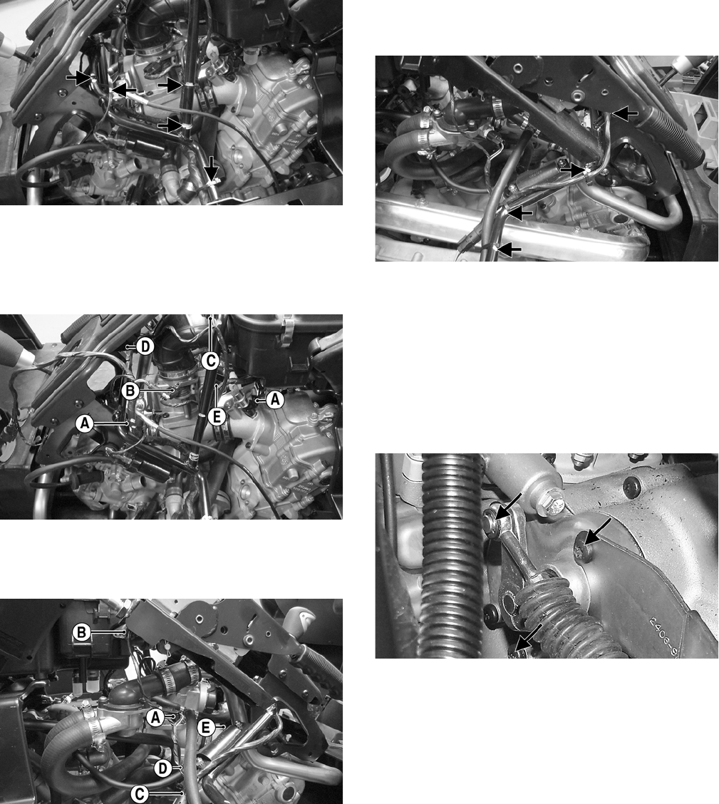
143
PR591A
23. Connect the front spark plug cap and front ignition
coil; then install the front and rear injector connec-
tors (A), MAP sensor (B), parking brake warning
switch (C), reverse override switch connector (D),
and ISC valve (E).
PR595A
24. From the right side, connect the ECT sensor (A), IAT
sensor (B), fuel pump/fuel gauge connector (C), rear
ignition coil (D), and TPS connector (E).
PR594A
25. Install nylon cable ties at all locations marked prior
to removing engine; then check for correct routing of
all wiring, hoses, and cables.
PR592A
26. Connect the negative battery cable and install the
battery hold-down.
27. Pour the recommended amount of oil into the
engine/transmission.
28. Remove the coolant bleed screw from the upper
coolant pipe near the thermostat; then pour the cor-
rect mixture of coolant into the radiator. When cool-
ant with no air bubbles flows from the bleed hole,
install the screw and tighten securely.
PR662A
29. Start the engine and check for oil or coolant leaks;
then check all fluid levels and correct as necessary.
30. Wipe off any spilled coolant or lubricant; then install
the floor, storage console, seat bases, center console,
and seats.
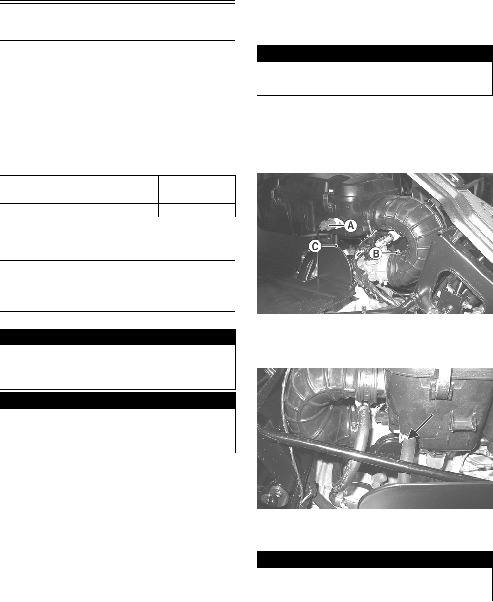
144
Fuel/Lubrication/Cooling
NOTE: Arctic Cat recommends the use of new gas-
kets, lock nuts, and seals and lubricating all internal
components when servicing the engine/transmis-
sion.
SPECIAL TOOLS
A number of special tools must be available to the techni-
cian when performing service procedures in this section.
Refer to the current Special Tools Catalog for the appro-
priate tool description.
NOTE: Special tools are available from the Arctic
Cat Service Department.
Electronic Fuel Injection
(XT/XTX)
TROUBLESHOOTING
1. Verify that the electric fuel pump is operating by lis-
tening for a “whirring” sound for approximately
three seconds after the ignition switch is turned to the
ON position. If no sound can be heard, see Electric
Fuel Pump/Fuel Level Sensor in this section.
2. Check for a flashing EFI icon on the LCD. If EFI is
flashing, see ECM Error Codes in the Electrical Sys-
tem section.
3. Make sure there is sufficient, clean gas in the gas
tank.
4. Verify that the battery is sufficiently charged to crank
the engine over at normal speed.
5. Check the air filter housing and air filter for contam-
ination. Clean or replace as necessary (see the Peri-
odic Maintenance section).
REMOVING THROTTLE BODY
1. Turn the ignition switch to the OFF position; then
remove the ignition switch key.
2. Remove the left and right seats; then remove the cen-
ter console and disconnect the battery.
3. Remove the connector from the IAT sensor (A); then
loosen the inlet boot clamp (B) and remove the
mounting screw (C).
PR486A
4. Disconnect the crankcase breather hose from the air
filter housing; then remove the air filter assembly
from the vehicle.
PR487A
5. Slowly disconnect the gasline hose connector from
the fuel rail.
Description p/n
Oil Pressure Test Kit 0644-495
Tachometer 0644-275
! WARNING
Whenever the gasline hoses are removed (other than for
pressure testing), the battery must be disconnected to
prevent inadvertent activation of the electronic fuel
pump.
! WARNING
Whenever any maintenance or inspection is performed
on the fuel system during which there may be fuel leak-
age, there should be no welding, smoking, open flames,
etc., in the area.
! WARNING
Do not turn the ignition switch to the ON position with
the hoses removed. Gasoline will be pumped by the
electric fuel pump causing a safety hazard.
! WARNING
Gasoline may be under pressure. Place an absorbent
towel under the connector to absorb any gasoline spray
when disconnecting.
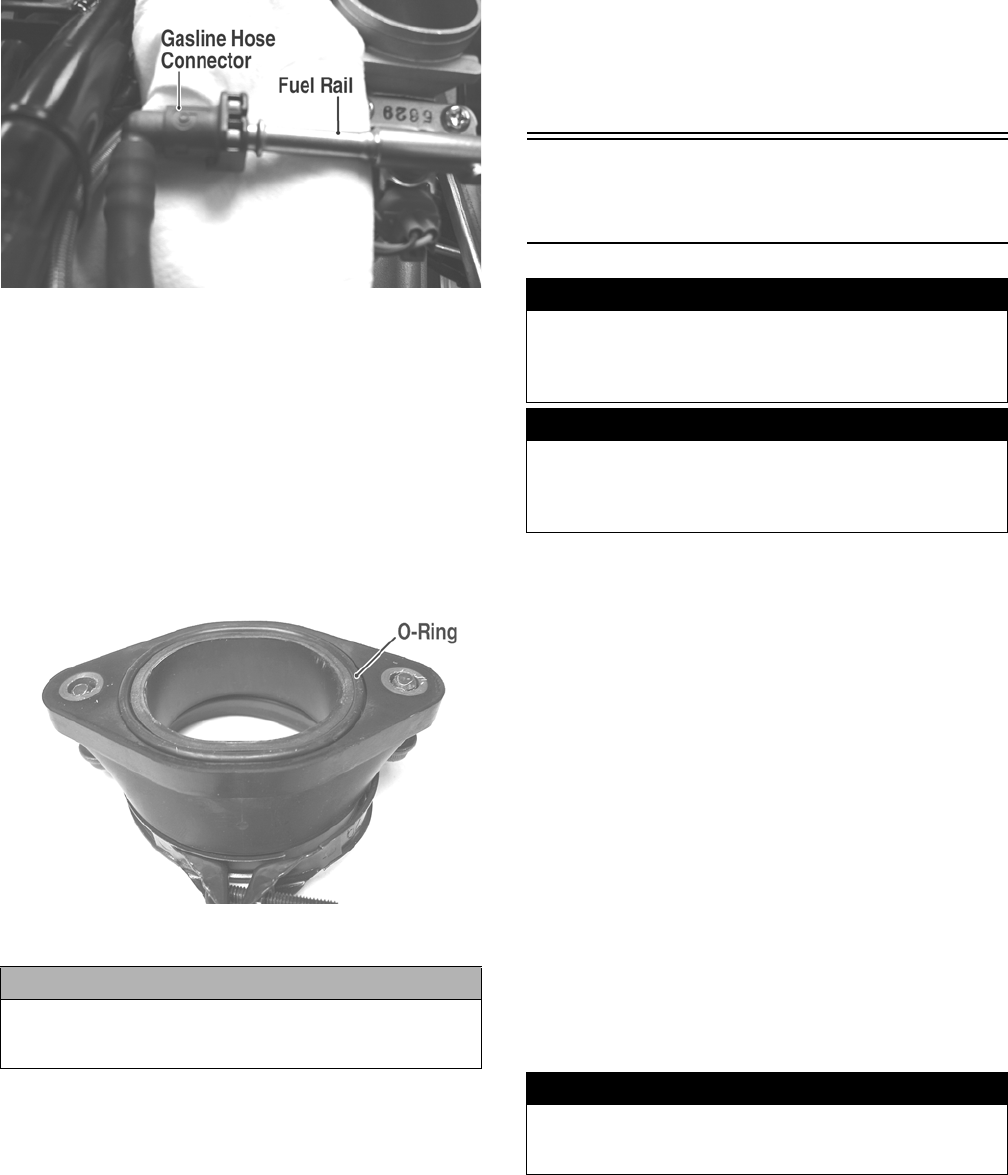
145
FI092A
6. Remove the screw securing the throttle actuator
cover to the throttle body; then remove the cover.
7. Remove the throttle cable from the actuator arm.
8. Loosen the outer jam nut securing the throttle cable
to the throttle body; then route the cable out of the
way.
9. Remove the electrical connectors from the throttle
body components.
10. Remove the throttle body assembly from the intake
pipe.
FI104A
11. Use tape to cover and seal the intake opening.
INSTALLING THROTTLE BODY
1. Install the throttle body into the intake pipe and
secure with the clamp. Tighten securely.
2. Place a new O-ring in the intake pipe; then position
the pipe onto the engine and secure with two cap
screws.
3. Connect the throttle cable to the throttle body and
adjust throttle cable free-play; then connect the
gasline hose.
4. Connect the electrical connectors to the throttle body
components.
5. Install the air filter assembly and secure with the
existing hardware; then connect the IAT sensor and
crankcase breather hose.
6. Install the center console and seats making sure the
seats lock securely in place.
Electronic Fuel Injection
(XTZ)
TROUBLESHOOTING
1. Verify that the electric fuel pump is operating by lis-
tening for a “whirring” sound for approximately
three seconds after the ignition switch is turned to the
ON position. If no sound can be heard, see Electric
Fuel Pump/Fuel Level Sensor in this section.
2. Check for a flashing EFI icon on the LCD. If EFI is
flashing, see ECM Error Codes in the Electrical Sys-
tem section.
3. Make sure there is sufficient, clean gas in the gas
tank.
4. Verify that the battery is sufficiently charged to crank
the engine over at normal speed.
5. Check the air filter housing and air filter for contam-
ination. Clean or replace as necessary (see the Peri-
odic Maintenance section).
REMOVING THROTTLE BODY
1. Turn the ignition switch to the OFF position; then
remove the ignition switch key.
2. Remove the left and right seats; then remove the cen-
ter console and disconnect the battery.
3. Remove the air inlet boot; then disconnect the throt-
tle position sensor (TPS) connector (A), manifold
absolute pressure (MAP) sensor connector (B), and
idle speed control (ISC) connector (C).
CAUTION
Any objects or liquid entering the intake opening will
fall into the engine causing severe damage if the engine
is turned over or started.
! WARNING
Whenever the gasline hoses are removed (other than for
pressure testing), the battery must be disconnected to
prevent inadvertent activation of the electronic fuel
pump.
! WARNING
Whenever any maintenance or inspection is performed
on the fuel system during which there may be fuel leak-
age, there should be no welding, smoking, open flames,
etc., in the area.
! WARNING
Do not turn the ignition switch to the ON position with
the hoses removed. Gasoline will be pumped by the
electric fuel pump causing a safety hazard.
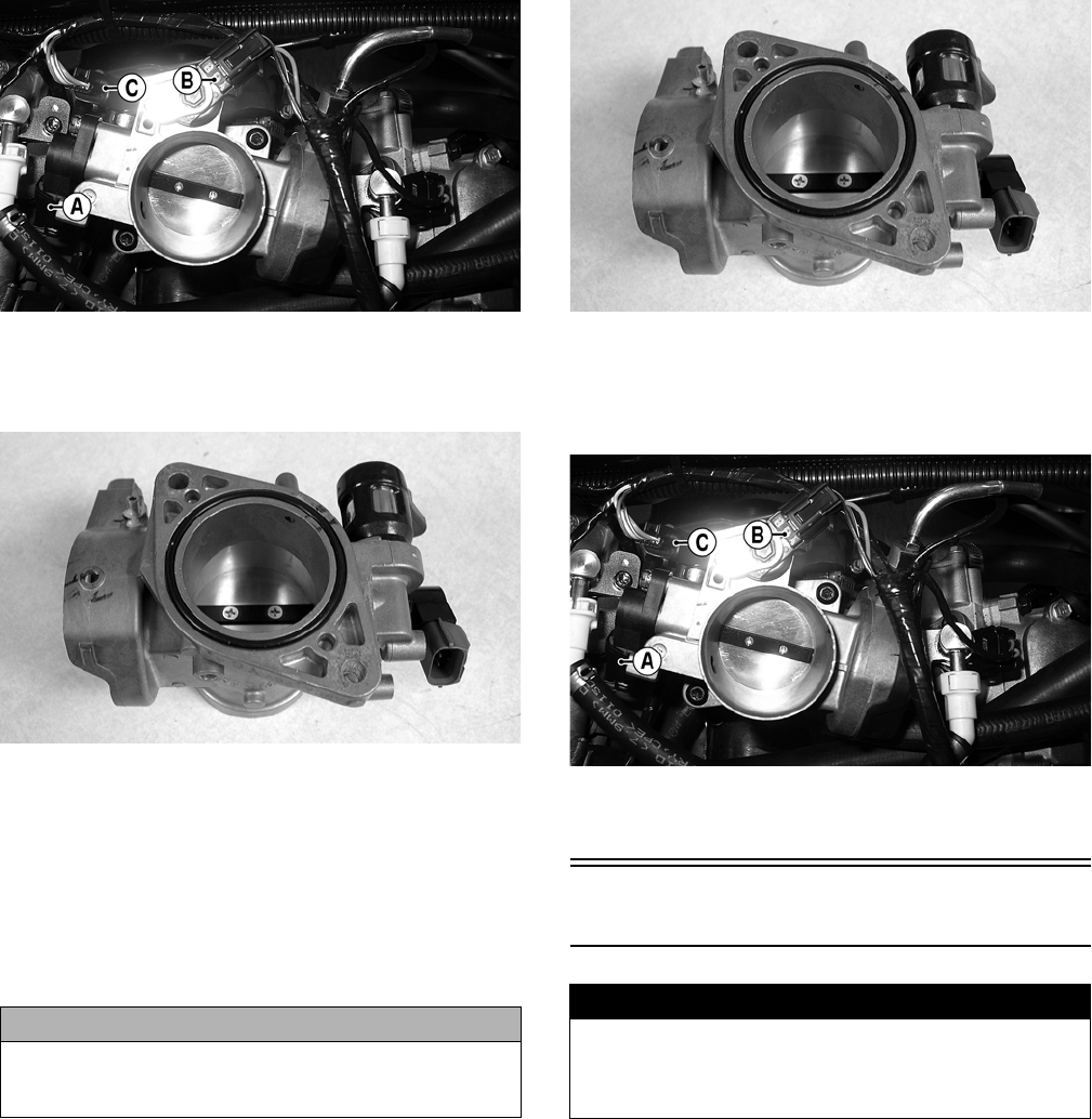
146
GZ094E
4. Remove the cap screws securing the throttle body to
the manifold; then lift the throttle body off the mani-
fold. Account for an O-ring.
GZ386
5. Remove the screw securing the throttle actuator
cover to the throttle body; then remove the cover.
6. Remove the throttle cable from the actuator arm.
7. Loosen the outer jam nut securing the throttle cable
to the throttle body. The throttle body can now be
removed from the vehicle.
8. Use tape to cover and seal the intake opening.
INSTALLING THROTTLE BODY
1. Connect the throttle cable to the throttle body and
adjust throttle cable free-play; then install the throttle
actuator cover and secure with the machine screw.
2. Remove the covering from the intake manifold open-
ing; then using a new O-ring, install the throttle body
onto the manifold and secure with the cap screws.
Tighten securely.
GZ386
3. Connect the TPS connector (A), MAP sensor con-
nector (B), and ISC connector (C) to the throttle
body; then install the air inlet boot and tighten the
clamps securely.
GZ094E
4. Install the center console and seats making sure the
seats lock securely in place.
Gas Tank
REMOVING
1. Remove the seats and center console; then remove
the left-side and right-side seat-bases.
2. Remove twelve cap screws and two self-tapping
screws securing the floorboard to the frame.
3. While pulling forward on the upper portion of the
floorboard, lift the rear panel above the seat lock
studs; then insert a small wood block to hold in posi-
tion.
CAUTION
Any objects or liquid entering the intake opening will
fall into the engine causing severe damage if the engine
is turned over or started.
! WARNING
Whenever any maintenance or inspection is made on
the fuel system during which there may be fuel leakage,
there should be no welding, smoking, open flames, etc.,
in the area.
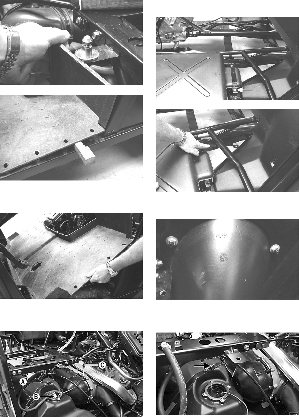
147
PR163
PR164
4. From the opposite side of the vehicle, repeat step 3;
then lift the rear of the floorboard up and lift the
floorboard out of the vehicle.
PR165
5. Disconnect the vent hose (A), gasline hose (B), and
fuel pump/fuel level sensor connector (C); then cap
the vent fitting and gas hose fitting.
PR698A
6. Remove the outer cap screw securing the front tank
hold-down; then swing the hold-down to the left.
PR167A
PR170
7. Remove four press-nuts securing the gas cap inset;
then remove the gas cap and inset. Install the gas cap.
PR168
8. Remove the joining cap screw and nut from the rear
gas tank hold-down strap; then remove the inside
hold-down strap.
PR699A
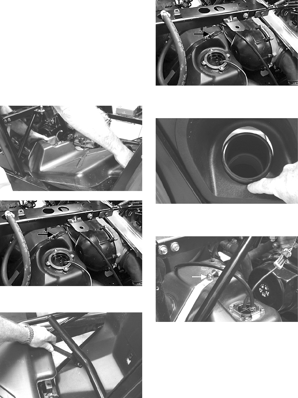
148
9. Lift and slide the tank forward raising the front of the
tank first; then turn the tank and lift out the right
side.
CLEANING AND INSPECTING
1. Clean all gas tank components with parts-cleaning
solvent.
2. Inspect all hoses for cracks or leaks.
3. Inspect gas tank cap and tank for leaks, holes, and
damaged threads.
4. Inspect the fuel level sensor for proper operation (see
Fuel Level Sensor in this section).
INSTALLING
1. Place the gas tank into position in the vehicle; then
install the inside rear hold-down strap.
PR173
PR699A
2. Swing the front hold-down to the right into position and
install the cap screw and nut. Do not tighten at this time.
PR171
3. Install the rear hold-down strap joining cap screw
and nut. Do not tighten at this time.
PR699A
4. Place the gas cap filler panel into position; then if
necessary, position the gas tank so the filler panel
and filler neck are not binding or rubbing.
PR176
5. Secure the filler panel with four press-nuts; then
tighten the hardware securing the hold-down straps
(from steps 2-3) securely.
PR166A
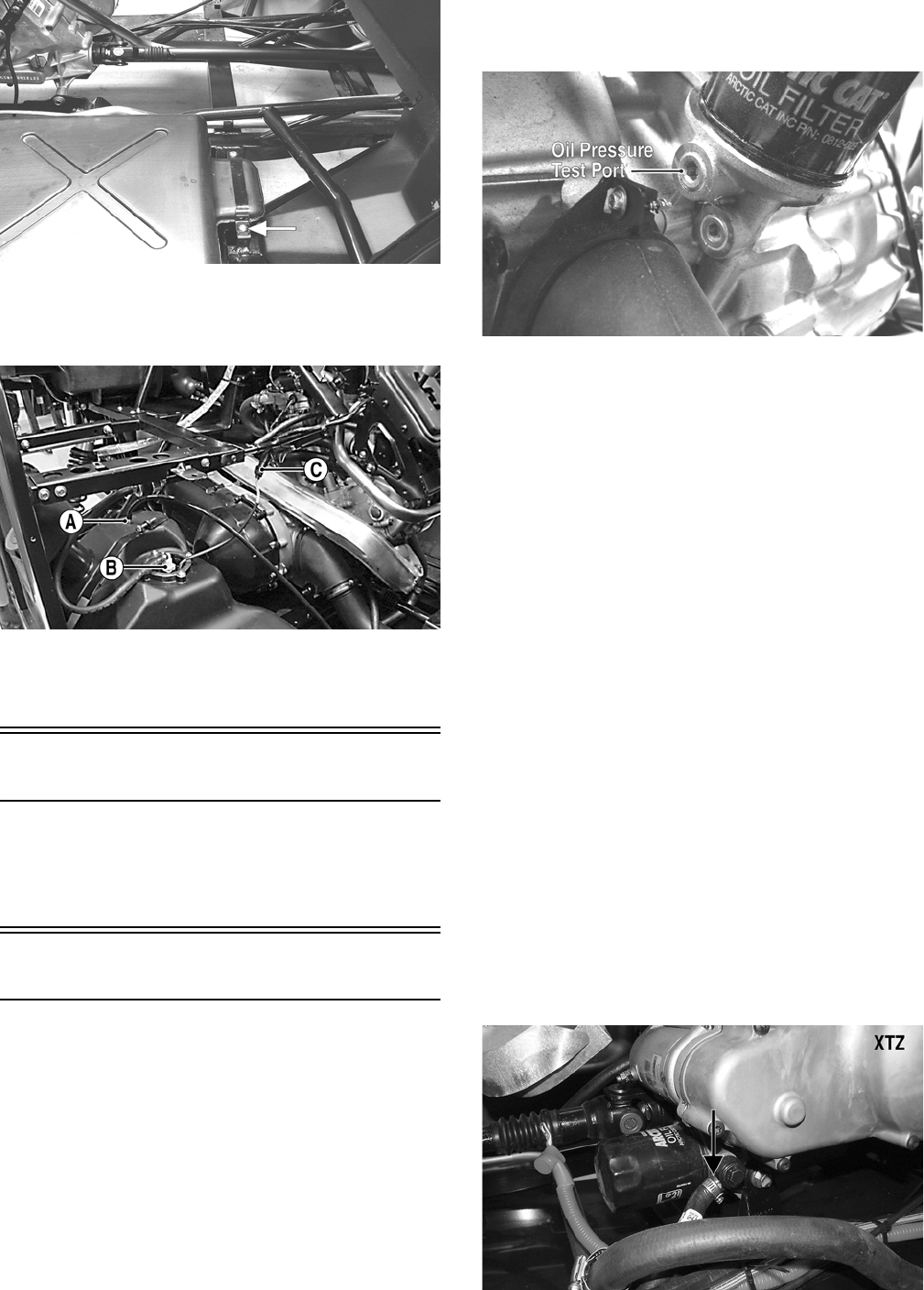
149
PR167A
6. Connect the vent hose (A) and gasline hose (B) to the
proper fittings; then connect the fuel pump/fuel level
sensor connector (C) to the main harness.
PR698A
7. Position the floorboard into the vehicle and secure with
the appropriate hardware; then install the center console,
seat-bases, and seats making sure the seats lock securely.
Gas/Vent Hoses
Replace the gas hose every two years. Damage from aging
may not always be visible. Do not bend or obstruct the rout-
ing of the vent hoses. Make certain the vent hoses are
securely connected and the opposite ends are always open.
Oil Filter/Oil Pump
NOTE: Whenever internal engine components wear
excessively or break and whenever oil is contami-
nated, the oil pump should be replaced.
TESTING OIL PUMP PRESSURE
(XT/XTX)
NOTE: The engine must be warmed up to operating
temperature (cooling fan cycling) for this test.
1. Remove the seats and center console; then remove
the left-side seat-base.
2. Tilt the cargo box back.
3. Remove the upper plug from the base of the oil filter;
then using an appropriate adapter, connect an oil
pressure gauge to the engine.
CF264A
NOTE: Some oil seepage may occur when installing
the oil pressure gauge. Wipe up oil residue with a cloth.
4. Set the parking brake and start the engine. Allow the
engine to warm up to operating temperature (with
cooling fan cycling).
5. Set the speedometer/tachometer to RPM. With the
engine running at 3000 RPM, the pressure gauge
must show 0.6-0.7 kg/cm2 (8.5-10 psi), on the XT or
1.2-1.5 kg/cm2 (17-21 psi) on the XTX.
6. Install the left-side seat-base; then install the center
console and seats making sure the seats lock
securely.
NOTE: If the oil pressure is lower than specified,
check for an oil leak, damaged oil seal, or defective
oil pump.
NOTE: If the oil pressure is higher than specified,
check for too heavy engine oil weight (see General
Information - Gasoline - Oil - Lubricant), clogged oil
passage, clogged oil filter, or improper installation of
the oil filter.
TESTING OIL PUMP PRESSURE (XTZ)
NOTE: The engine must be warmed up to operating
temperature (cooling fan cycling) for this test.
1. Remove both seats and center console; then remove
the oil hose from the fitting nearest the oil filter base.
PR617B
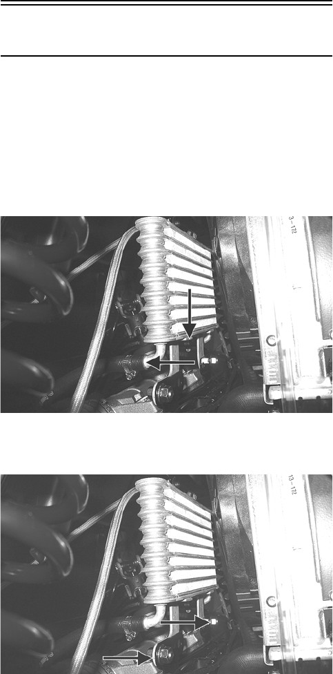
150
2. Using a suitable “T” fitting, connect Oil Pressure
Test Kit to the oil fitting and hose. Tighten all clamps
securely.
NOTE: Some oil seepage may occur when installing the
oil pressure gauge. Wipe up oil residue with a cloth.
3. Set the parking brake and start the engine. Allow the
engine to warm up to operating temperature (with
cooling fan cycling).
4. Set the speedometer/tachometer to RPM. With the
engine running at 3000 RPM, the pressure gauge
must show 1.05-1.2 kg/cm2 (15-17 psi).
5. Remove the test kit from the vehicle and install the
oil hose. Tighten the clamps securely.
6. Install the seats, seat base, and center console as
required making sure the seats lock securely.
NOTE: If the oil pressure is lower than specified,
check for an oil leak, damaged oil seal, or defective
oil pump.
NOTE: If the oil pressure is higher than specified,
check for too heavy engine oil weight (see the Gen-
eral Information section), clogged oil passage,
clogged oil filter, or improper installation of the oil fil-
ter.
REMOVING/DISASSEMBLING
1. Remove the oil pump from the engine (see Left-Side
Components (XT/XTX) or Center Crankcase Com-
ponents (XTZ) in the Engine/Transmission section).
2. Remove the Phillips-head screw on the back side of
the pump and separate the pump housing and cover.
Note the position of the inner and outer rotors and
alignment pin for assembly.
3. Remove oil pump components.
CLEANING AND INSPECTING
1. Clean all oil-pump components.
2. Inspect the rotors for scoring and gouges.
3. Inspect the alignment pin, driveshaft, and driven
sprocket for damage.
4. Inspect the pump housing and cover for cracks or
damage.
ASSEMBLING/INSTALLING
1. Place the rotors into the pump housing making sure
the alignment pin is in the groove of the rotor.
2. Place the cover onto the pump housing.
3. Secure the pump with the Phillips-head screw coated
with red Loctite #271. Tighten to 8 ft-lb.
4. Install the oil pump into the engine (see Left-Side
Components (XT/XTX) or Center Crankcase Com-
ponents (XTZ) in the Engine/Transmission section).
Oil Cooler (XTZ)
This model has an oil cooler in addition to the liquid
cooling system. An oil cooler kit may be installed on any
Arctic Cat ROV.
REMOVING
1. Loosen the clamps securing the oil hoses to the oil
cooler; then place a shallow pan or absorbent towel
under the connection and remove the hoses.
PR484A
2. Remove the flange nuts and cap screws from the oil
cooler mountings and remove the oil cooler.
PR484B
CLEANING AND INSPECTING
1. Prior to washing, inspect the oil cooler for signs of
leaks such as oily dirt build-up.
2. Wash the cooling fins using a garden hose and hot,
soapy water and a soft brush.
3. Inspect all mounting brackets and the oil inlet and
outlet for cracks or bends.
INSTALLING
1. Place the oil cooler into position and secure with the
existing hardware. Tighten securely.
2. Connect the oil hoses and secure with the hose
clamps. Tighten securely.
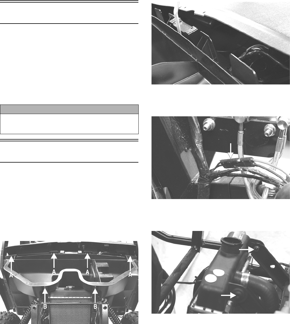
151
Liquid Cooling System
When filling the cooling system, use premixed Arctic Cat
Antifreeze. While the cooling system is being filled, air
pockets may develop; therefore, open the bleed screw on
the upper coolant pipe or the thermostat housing to allow
air to bleed from the cooling system. When clear coolant
(no bubbles) is present, tighten the bleed screw securely;
then fill the cooling system to the bottom of the stand
pipe in the radiator neck. Run the engine for five minutes
after the initial fill, shut the engine off, and then “top-off”
the cooling system to the bottom of the stand pipe in the
radiator neck.
Radiator
REMOVING
1. Remove the screws securing the dash assembly to
the frame (two on each side, two front center, and
three lower-rear dash). Slide the dash rearward
approximately four inches.
2. Remove four torx-head screws (A) securing the
under-hood storage box to the frame; then remove
two cap screws with nuts (B) at the front of the stor-
age box.
PR182A
3. While lifting up on the front of the storage box, pry
the rear center clear of the center dash mount and
remove the storage box.
PR186
4. Drain the coolant into a suitable container; then dis-
connect the cooling fan wire connector from the
main harness.
PR183A
5. Remove the two shoulder bolts and nuts securing the
radiator to the frame; then disconnect the upper and
lower coolant hoses.
PR184A
6. Lift the radiator assembly from the vehicle. Account
for two upper and two lower rubber mounting grom-
mets.
CLEANING AND INSPECTING
1. Flush the radiator with water to remove any contami-
nants.
2. Inspect the radiator for leaks and damage.
3. Inspect all hoses for cracks and deterioration.
4. Inspect all fasteners and grommets for damage or
wear.
CAUTION
After operating the vehicle for the initial 5-10 minutes,
stop the engine, allow the engine to cool down, and
check the coolant level. Add coolant as necessary.
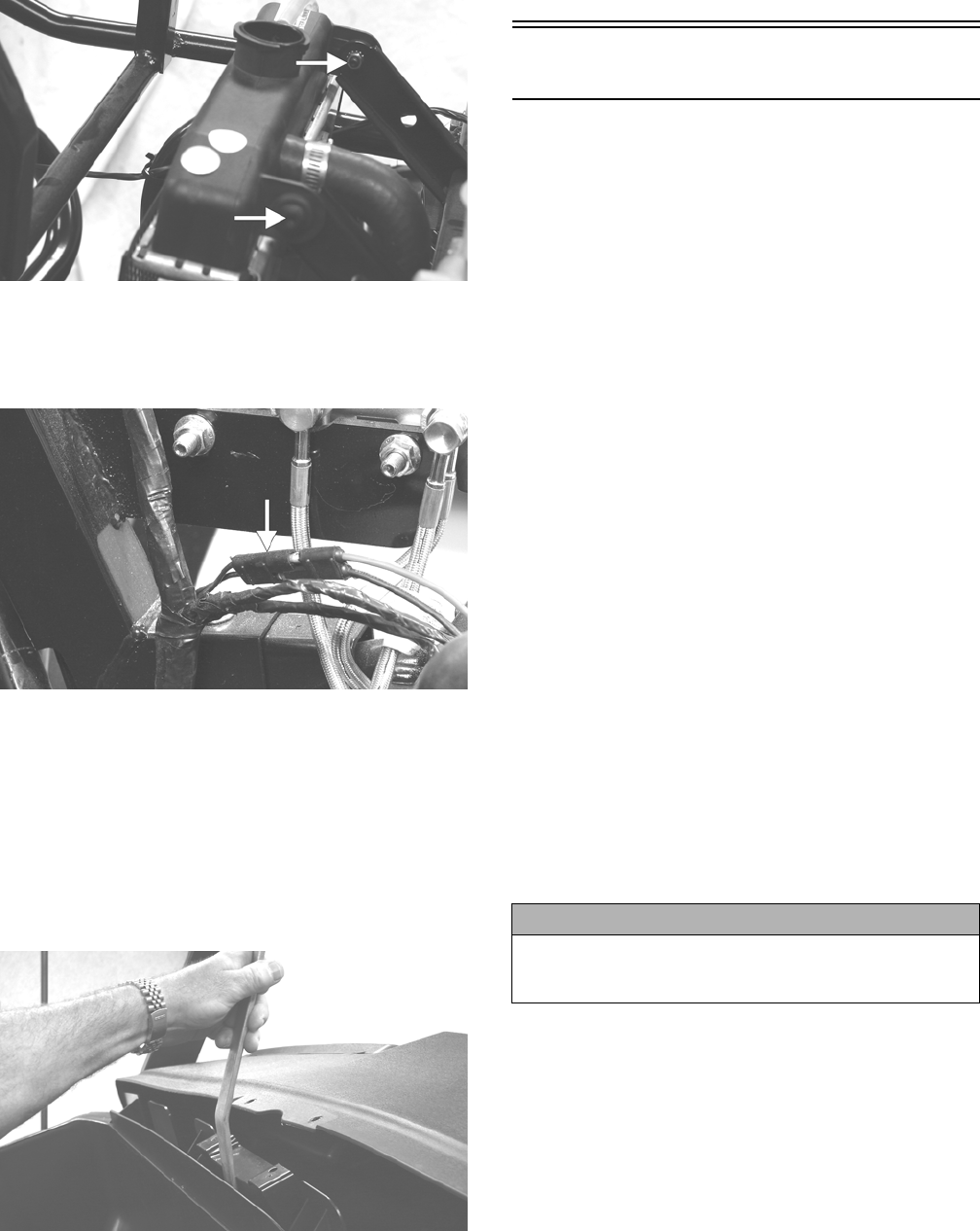
152
INSTALLING
1. Place the radiator into position making sure the
grommets are correctly installed; then secure to the
mounts with the two shoulder bolts and nuts. Tighten
securely.
PR184A
2. Connect the upper and lower coolant hoses to the
radiator and secure with the appropriate hose clamps;
then connect the cooling fan wire connector to the
main harness.
PR183A
3. Open the high-point bleed screw on the upper cool-
ant pipe to allow trapped air to escape. Tighten
securely after filling.
4. Pour the recommended coolant into the radiator and
secure the radiator cap.
5. Place the storage box into position and using a
smooth, flat pry-bar, pry the center of the box past
the dash mount; then secure with the appropriate fas-
teners.
PR187
6. Slide the dash forward into position; then secure the
dash with the appropriate hardware.
7. Start the engine and warm up to operating tempera-
ture; then verify the coolant level is at the bottom of
the stand pipe in the radiator neck. Add coolant as
necessary.
Thermostat (XT/XTX)
REMOVING
1. Drain approximately one quart of coolant from the
cooling system.
2. Remove the two cap screws securing the thermostat
housing to the cylinder head. Account for a thermo-
stat with seal.
INSPECTING
1. Inspect the thermostat for corrosion, wear, or spring
damage.
2. Using the following procedure, inspect the thermo-
stat for proper operation.
A. Suspend the thermostat in a container filled with
water.
B. Heat the water and monitor the temperature with a
thermometer.
C. The thermostat should start to open at 71.0-86.0°
C (160-187° F).
D. If the thermostat does not open, it must be
replaced.
3. Inspect all coolant hoses, connections, and clamps
for deterioration, cracks, and wear.
NOTE: All coolant hoses and clamps should be
replaced every four years or 4000 miles.
INSTALLING
1. Place the thermostat with seal into the thermostat
housing; then secure the thermostat housing to the
cylinder head with the two cap screws.
CAUTION
When installing the thermostat, make sure the bleed
holes are straight up and down or air will remain
trapped causing engine damage due to overheating.
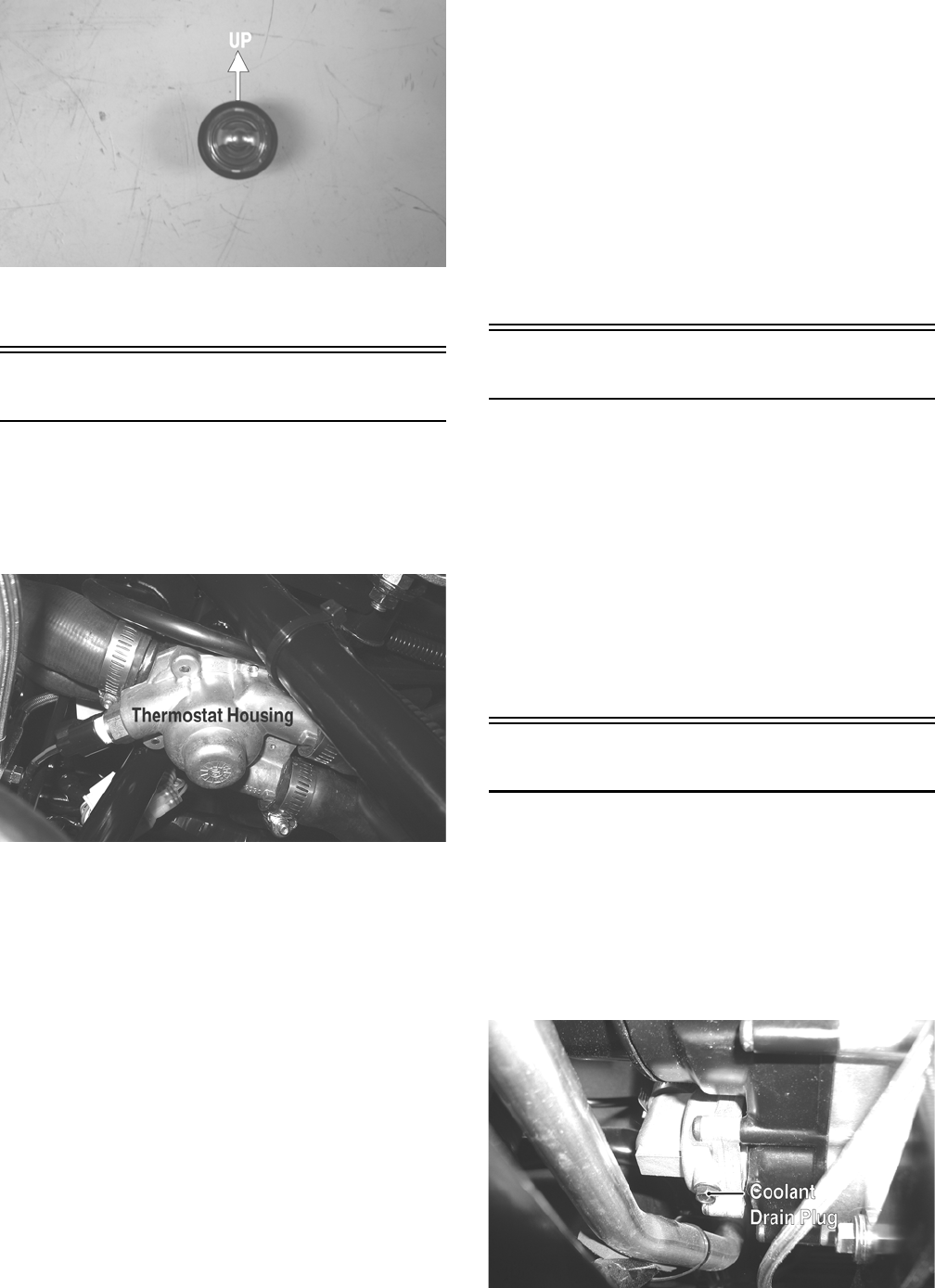
153
PR281A
2. Fill the cooling system with the recommended
amount of antifreeze. Check for leakage.
Thermostat (XTZ)
REMOVING
NOTE: The thermostat is located in a housing
in-line with the upper radiator hoses under the air fil-
ter housing.
GZ036A
1. Drain approximately one quart of coolant from the
cooling system.
2. Remove the four machine screws securing the ther-
mostat housing together. Remove the thermostat and
account for an O-ring.
INSPECTING
1. Inspect the thermostat for corrosion or spring dam-
age.
2. Using the following procedure, inspect the thermo-
stat for proper operation.
A. Suspend the thermostat in a container filled with
water.
B. Heat the water and monitor the temperature with a
thermometer.
C. The thermostat should start to open at 71.0-86.0°
C (160-187° F).
D. If the thermostat does not open, it must be
replaced.
3. Inspect all coolant hoses, connections, and clamps
for deterioration, cracks, and wear.
NOTE: All coolant hoses and clamps should be
replaced every four years or 4000 miles.
INSTALLING
1. Place the thermostat and O-ring into the thermostat
housing; then secure the thermostat housing together
with the four machine screws.
2. Fill the cooling system with the recommended
amount of antifreeze. Check for leakage.
Fan
REMOVING
1. Remove the radiator.
2. Remove the fan assembly from the radiator.
INSTALLING
1. Position the fan assembly on the radiator; then secure
with existing hardware.
NOTE: The fan wiring must be in the upper-right
position.
2. Install the radiator.
Water Pump (XT/XTX)
NOTE: The water pump is not a serviceable compo-
nent. If the pump is defective or if the mechanical
seal is leaking (coolant dripping from the discharge
hole), the water pump must be replaced.
REMOVING
1. Remove the radiator cap; then remove the water
pump coolant drain plug and drain the coolant.
PR122A
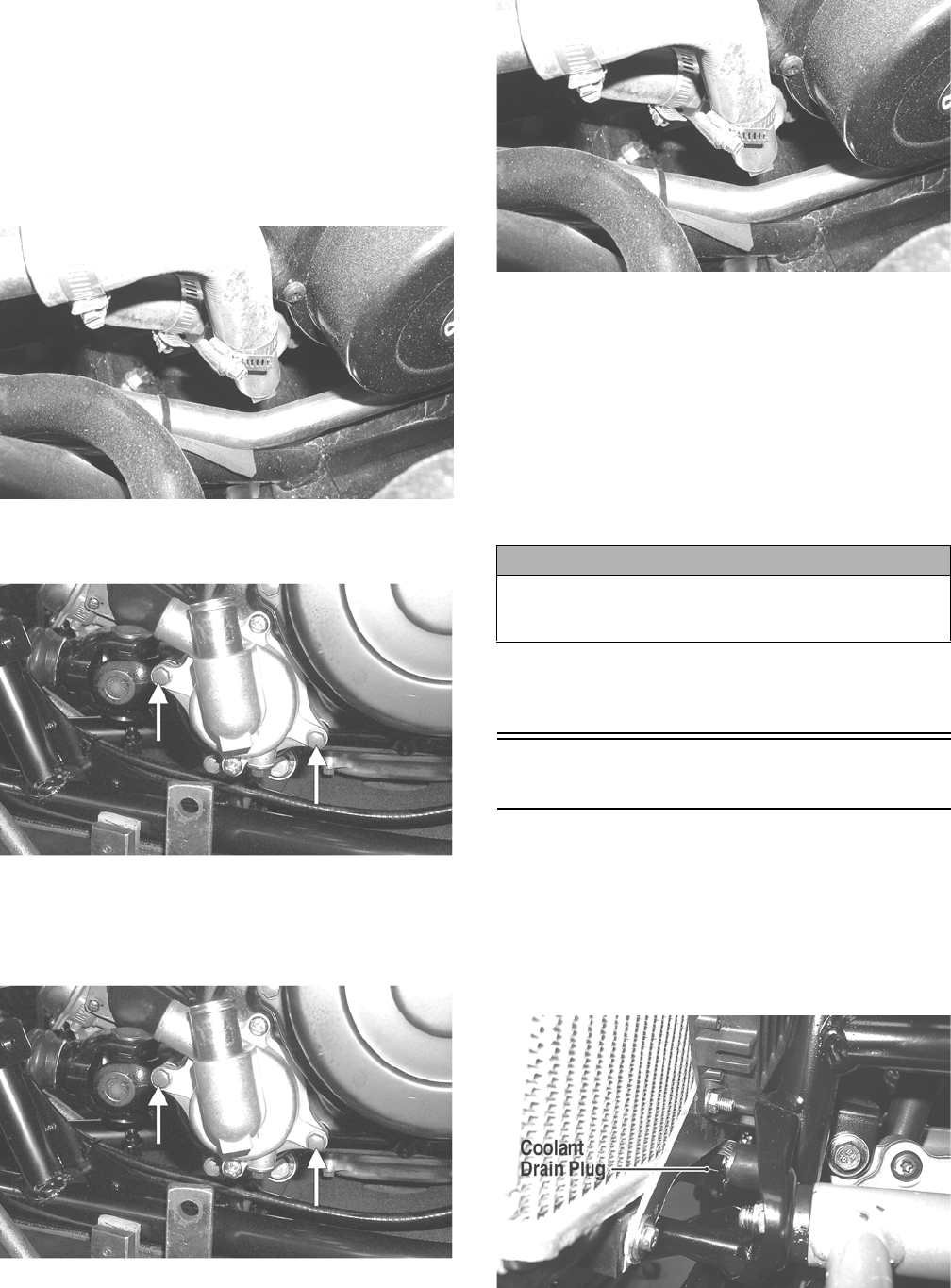
154
NOTE: Always use a large container and have suffi-
cient floor drying material available when draining
the coolant in case of coolant spillage.
2. Drain the oil from the engine/transmission.
3. Remove the seats and center console; then remove
the right-side seat-base.
4. Loosen the coolant hose clamps and slide the clamps
away from the hose ends.
PR132
5. Remove the two cap screws securing the water pump
to the engine; then remove the water pump.
CC786A
INSTALLING
1. Secure the water pump to the engine with the two
cap screws tightened securely.
CC786A
2. Connect the two coolant hoses to the water pump and
secure with the clamps; then install the water pump
coolant drain plug.
PR132
3. Fill the engine/transmission with the proper amount
of recommended oil.
4. Fill the cooling system with the proper amount of
recommended coolant.
NOTE: While the cooling system is being filled, air
pockets may develop; therefore, run the engine for
five minutes after the initial fill, shut the engine off,
and then fill the cooling system.
5. Check the entire cooling system for leakage.
6. Install the right-side seat-base; then install the center
console and seats making sure the seats lock
securely.
Water Pump (XTZ)
NOTE: The water pump is a non-serviceable compo-
nent. It must be replaced as an assembly.
REMOVING
1. Remove the coolant drain plug; then remove the
radiator cap and drain the coolant into a suitable con-
tainer.
GZ093A
CAUTION
After operating the vehicle for the initial 5-10 minutes,
stop the engine, allow the engine to cool down, and
check the coolant level. Add coolant as necessary.
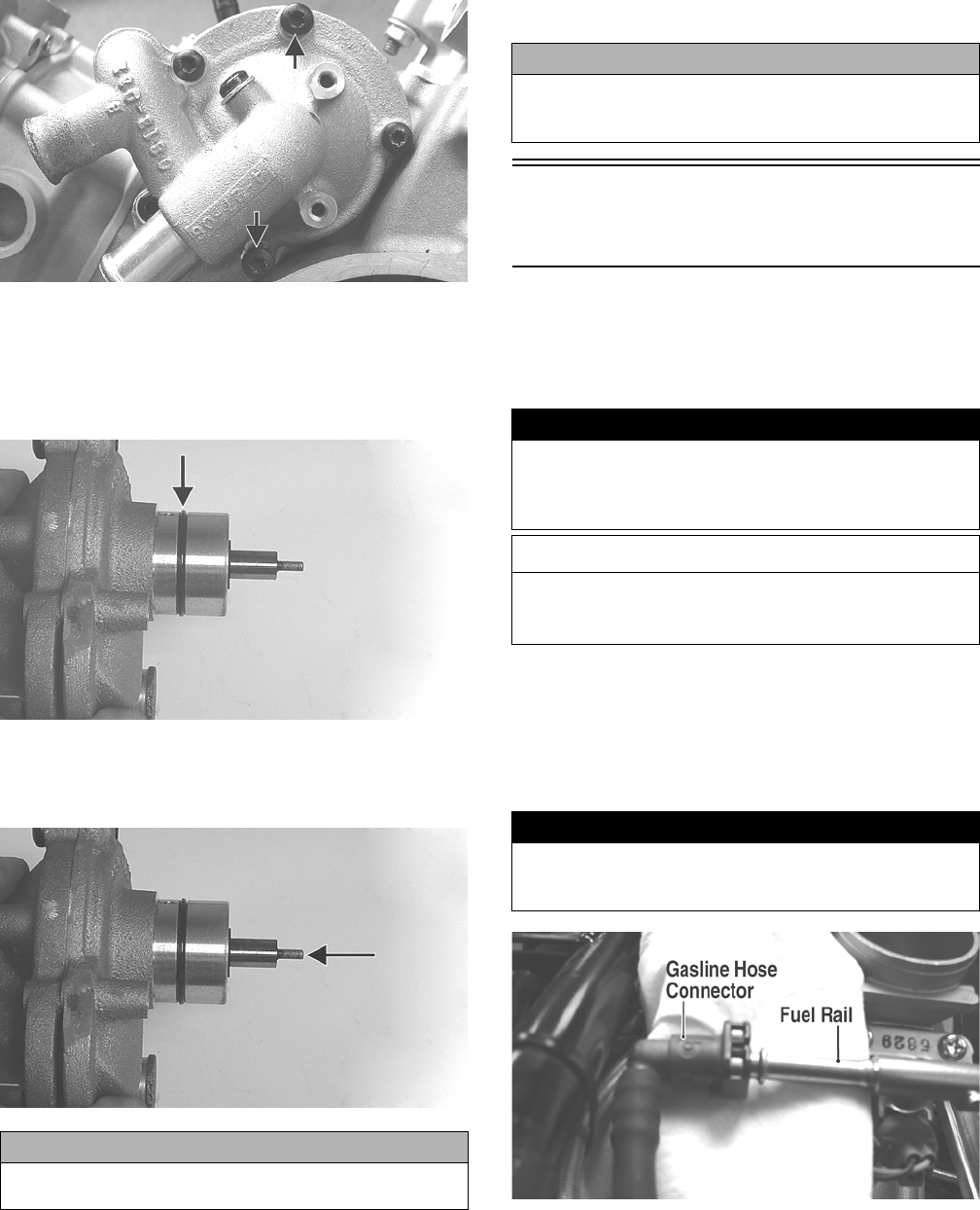
155
NOTE: Always use a large container and have suffi-
cient floor drying material available when draining
the coolant in case of coolant spillage.
2. Remove the coolant hoses from the water pump; then
remove two cap screws securing the water pump to
the crankcase.
GZ230A
3. Remove the water pump from the engine.
INSTALLING
1. Install a new O-ring onto the water pump and lightly
coat with clean engine oil.
GZ252C
2. Install the water pump assembly onto the engine
aligning the flat drive on the water pump to the slot
in the driven gear shaft.
GZ252D
3. Secure the water pump with the two cap screws and
tighten securely; then connect the coolant hoses and
secure with hose clamps.
4. Tighten the coolant drain plug securely; then fill the
cooling system with appropriate mixed coolant and
install the radiator cap.
5. Start the engine and check for coolant leaks; then add
coolant if necessary to proper level.
Electric Fuel Pump/Fuel
Level Sensor
The electric fuel pump and fuel level sensor are not ser-
viceable components. If either component fails, it must
be replaced.
TESTING
1. Turn the ignition switch ON and listen for a momen-
tary “whirring” sound of the pump building pressure.
If the sound is heard (10 seconds), no electrical
checks are necessary. Turn the ignition switch OFF.
2. Disconnect the gasline hose from the fuel rail; then
install a suitable pressure gauge.
FI092A
CAUTION
Do not force the water pump housing into the crankcase
or sever engine damage may occur.
CAUTION
After operating the vehicle for the initial 5-10 minutes,
stop the engine, allow the engine to cool down, and
check the coolant level. Add coolant as necessary.
! WARNING
Whenever any maintenance or inspection is made on
the fuel system during which there may be fuel leakage,
there should be no welding, smoking, open flames, etc.,
in the area.
AT THIS POINT
Prior to removing the electric fuel pump, the following
check should be performed to determine that removal
is necessary.
! WARNING
Gasoline may be under pressure. Place an absorbent
towel under the connector to absorb any gasoline spray
when disconnecting.
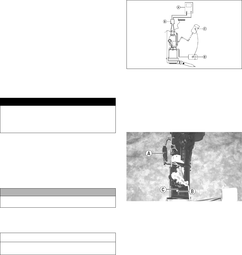
156
3. Turn the ignition switch to the ON position. The fuel
pressure should build until the pump shuts off. Pres-
sure should read 3.0 kg-cm2 (43 psi).
4. If the pump is not running, disconnect the fuel
pump/sensor connector by reaching under the rear
rack from behind.
5. Connect a multimeter to the power supply leads with
the red tester lead to the red wire and the black tester
lead to the black wire; then turn the ignition switch to
the ON position. The meter should read battery volt-
age. If battery voltage is indicated and the fuel pump
does not run, replace the pump assembly. If no bat-
tery voltage is indicated, check the ECM and the
vehicle tilt sensor.
REMOVING
1. Remove the key from the ignition switch.
2. Remove the seats, center console, and right-side
seat-base; then disconnect the negative battery cable.
3. Disconnect the electrical plug from the main harness;
then disconnect the gasline hose from the fuel pump.
4. Mark the fuel pump mounting and gas tank for
installing purposes; then remove the screws securing
the fuel pump to the gas tank and remove the fuel
pump.
5. Using duct tape or other suitable means, cover the
fuel pump opening.
INSPECTING
1. Inspect the fuel screen and blow clean with low pres-
sure compressed air.
2. Move the float lever and check for free movement.
The float assembly should return to the lower posi-
tion without force. If not, replace the fuel level sen-
sor assembly.
3. Test the fuel level sensor by connecting a multimeter
(A) to the fuel level sensor leads (B); then select
OHMS. The multimeter should show 5 ohms at full
fuel position (C) and 95 ohms at empty fuel position
(D).
ATV2116
NOTE: If readings are erratic, clean the resistor
wiper and resistor with clean alcohol and retest. If
still not correct, replace the fuel level sensor.
4. To replace the fuel level sensor, use the following
procedure.
A. Disconnect the two-wire connector (A); then
press the fuel level sensor toward the top of the
fuel pump to release it from the mounting slot (B).
FI460A
B. Engage the tabs (C) of the fuel level sensor into
the mounting slot (B) and press toward the bottom
of the fuel pump to latch in place; then connect
the two-wire connector (A).
INSTALLING
1. Place the fuel pump assembly into the gas tank with
a new gasket aligning the match marks; then secure
with the four screws. Tighten securely.
NOTE: It is important to install the fuel pump with
the correct orientation to ensure adequate float lever
clearance.
2. Connect the gasline hose to the fuel pump pipe and
secure with the hose clamp; then connect the electri-
cal plug to the main harness.
3. Connect the negative battery cable; then turn the
ignition switch to the ON position and verify that no
gas leaks are present, the pump runs for 2-3 seconds,
and the gas gauge reading is normal.
4. Start the engine to verify proper engine operation;
then shut off the engine and install the right-side
seat-base, center console, and seats making sure the
seats lock securely into place.
! WARNING
Always ensure that power cannot be inadvertently
applied to the ignition/ECM when working on the fuel
system. If the ignition switch is turned on, the electric
fuel pump will start and gas could be rapidly pumped
and spilled resulting in fire and severe injury.
CAUTION
Take care not to damage the float or float arm or
replacement of the entire assembly will be necessary.
AT THIS POINT
If the pump has failed earlier test and must be
replaced, proceed to INSTALLING.

157
Troubleshooting
Problem: Starting impaired
Condition Remedy
1. Gas contaminated 1. Drain gas tank and fill with clean gas
Problem: Idling or low speed impaired
Condition Remedy
1. TPS out of adjustment 1. Adjust TPS
Problem: Medium or high speed impaired
Condition Remedy
1. High RPM “cut out” against RPM limiter 1. Decrease RPM speed
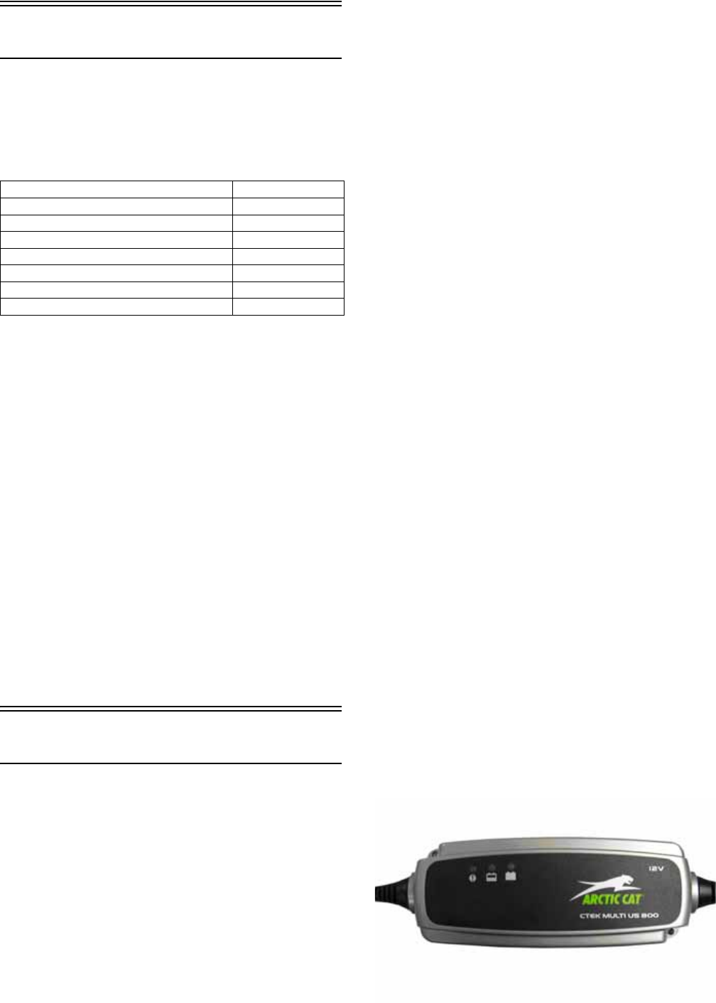
158
Electrical System
SPECIAL TOOLS
A number of special tools must be available to the techni-
cian when performing service procedures in this section.
Refer to the current Special Tools Catalog for the appro-
priate tool description.
NOTE: Special tools are available from the Arctic
Cat Service Department.
TESTING ELECTRICAL
COMPONENTS
All of the electrical tests should be made using the Fluke
Model 73 Multimeter or Model 77 Multimeter and when
testing peak voltage, the Peak Voltage Reading Adapter
must be used. If any other type of meter is used, readings
may vary due to internal circuitry. When troubleshooting
a specific component, always verify first the fuse(s) are
good, the bulb(s) are good, the connections are clean and
tight, the battery is fully charged, and all appropriate
switches are activated.
NOTE: For absolute accuracy, all tests should be
made at room temperature of 68° F.
ELECTRICAL CONNECTIONS
The electrical connections should be checked periodi-
cally for proper function. In case of an electrical failure,
check fuses, connections (for tightness, corrosion, dam-
age), and/or bulbs.
Battery
The battery is located in a compartment in front of the
left-rear wheel under the driver seat.
NOTE: To access the battery box, the driver’s seat
must be removed.
After being in service, batteries require regular cleaning
and recharging in order to deliver peak performance and
maximum service life. The following procedures are rec-
ommended for cleaning and maintaining lead-acid batter-
ies. Always read and follow instructions provided with
battery chargers and battery products.
NOTE: Refer to all warnings and cautions provided
with the battery or battery maintainer/charger.
Loss of battery charge may be caused by ambient temper-
ature, ignition OFF current draw, corroded terminals, self
discharge, frequent start/stops, and short engine run
times. Frequent winch usage, snowplowing, extended
low RPM operation, short trips, and high amperage
accessory usage are also reasons for battery discharge.
Maintenance Charging
NOTE: Arctic Cat recommends the use of the CTEK
Multi US 800 or the CTEK Multi US 3300 for battery
maintenance charging. Maintenance charging is
required on all batteries not used for more than two
weeks or as required by battery drain.
1. When charging a battery in the vehicle, be sure the
ignition switch is in the OFF position.
NOTE: Be sure to maintain the fluid of the battery at
the UPPER LEVEL. Use only distilled water when
adding fluid to these batteries.
2. Clean the battery terminals with a solution of baking
soda and water.
3. Be sure the charger and battery are in a well-venti-
lated area and ensure the battery charger cables will
not contact any battery acid. Be sure the charger is
unplugged from the 110-volt electrical outlet.
4. Connect the red terminal lead from the charger to the
positive terminal of the battery; then connect the
black terminal lead of the charger to the negative ter-
minal of the battery.
NOTE: Optional battery charging adapters are avail-
able from your authorized Arctic Cat dealer to con-
nect directly to your vehicle from the recommended
chargers to simplify the maintenance charging pro-
cess. Check with your authorized Arctic Cat dealer
for proper installation of these charging adapter con-
nectors.
5. Plug the battery charger into a 110-volt electrical
outlet.
6. If using the CTEK Multi US 800, there are no further
buttons to push. If using the CTEK Multi US 3300,
press the Mode button (A) at the left of the charger
until the Maintenance Charge Icon (B) at the bottom
illuminates. The Normal Charge Indicator (C) should
illuminate on the upper portion of the battery char-
ger.
800E
Description p/n
Fluke Model 73 Multimeter 0644-191
Fluke Model 77 Multimeter 0644-559
Timing Light 0644-296
MaxiClips 0744-041
Peak Voltage Reading Adapter 0644-307
Test Plug/Error Code List 0444-216
TPS Analyzer 0644-299
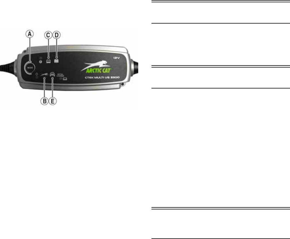
159
NOTE: The maintainer/charger will charge the bat-
tery to 95% capacity at which time the Maintenance
Charge Indicator (D) will illuminate and the main-
tainer/charger will change to pulse/float mainte-
nance. If the battery falls below 12.9 DC volts, the
charger will automatically start again at the first step
of the charge sequence.
3300A
NOTE: Not using a battery charger with the proper
float maintenance will damage the battery if con-
nected over extended periods.
Charging
NOTE: Arctic Cat recommends the use of the CTEK
Multi US 800 or the CTEK Multi US 3300 for battery
maintenance charging.
1. Be sure the battery and terminals have been cleaned
with a baking soda and water solution.
2. Be sure the charger and battery are in a well-venti-
lated area and ensure the battery charger cables will
not contact any battery acid. Be sure the charger is
unplugged from the 110-volt electrical outlet.
3. Connect the red terminal lead from the charger to the
positive terminal of the battery; then connect the
black terminal lead of the charger to the negative ter-
minal of the battery.
4. Plug the charger into a 110-volt electrical outlet.
5. By pushing the Mode button (A) on the left side of
the charger, select the Normal Charge Icon (E). The
Normal Charge Indicator (C) should illuminate on
the upper left portion of the charger.
6. The battery will charge to 95% of its capacity at
which time the Maintenance Charge Indicator (D)
will illuminate.
NOTE: For optimal charge and performance, leave
the charger connected to the battery for a minimum 1
hour after the Maintenance Charge Indicator (D) illu-
minates. If the battery becomes hot to the touch, stop
charging. Resume after it has cooled.
7. Once the battery has reached full charge, unplug the
charger from the 110-volt electrical outlet.
NOTE: If, after charging, the battery does not perform
to operator expectations, bring the battery to an autho-
rized Arctic Cat dealer for further troubleshooting.
RPM Limiter
NOTE: The ROV is equipped with an ECM that
retards ignition timing when maximum RPM is
approached. When the RPM limiter is activated, it
could be misinterpreted as a high-speed misfire.
Switches
Each time the vehicle is used, switches should be
checked for proper operation. Use the following list
for reference.
A. Ignition/start switch — engine will run; starter
will engage.
B. Drive select switch — differential will engage
(4WD)/disengage (2WD).
C. Reverse/neutral/high/low switch — R/N/H/L will
be indicated on the LCD.
D. Headlight switch — high beam, low beam, and
lights off can be selected.
E. Brake switch — brakelight illuminates and starter
can be engaged with vehicle in gear.
Accessory
Receptacle/Connector
NOTE: This test procedure is for either the recepta-
cles or the connectors.
VOLTAGE
1. Turn the ignition switch to the ON position; then set
the meter selector to the DC Voltage position.
2. Connect the red tester lead to the red/white wire or
the positive connector; then connect the black tester
lead to ground.
3. The meter must show battery voltage.
NOTE: If the meter shows no battery voltage, trou-
bleshoot the battery, fuse, receptacle, connector, or
the main wiring harness.
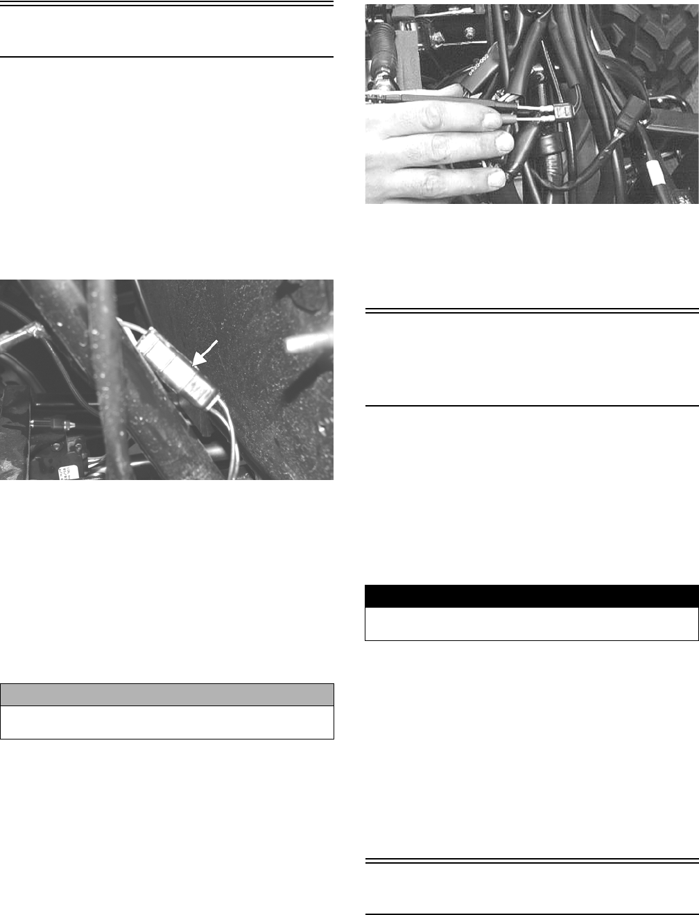
160
Brakelight Switch
The switch connector is the two-prong black connector
below the master cylinder.
NOTE: The ignition switch must be in the ON posi-
tion.
VOLTAGE (Wiring Harness
Connector)
1. Set the meter selector to the DC Voltage position.
2. Connect the red tester lead to the orange wire; then
connect the black tester lead to ground.
PR276A
3. The meter must show battery voltage.
NOTE: If the meter shows no battery voltage, trou-
bleshoot the battery, fuse, switch, or the main wiring
harness.
NOTE: If the meter shows battery voltage, the main
wiring harness is good; proceed to test the
switch/component, the connector, and the switch wir-
ing harness for resistance.
RESISTANCE (Switch Connector)
NOTE: The brake pedal must be depressed for this
test.
1. Set the meter selector to the OHMS position.
2. Connect the red tester lead to one black wire; then
connect the black tester lead to the other black wire.
AR621D
3. When the lever is depressed, the meter must show
less than 1 ohm.
NOTE: If the meter shows more than 1 ohm of resis-
tance, replace the switch.
Engine Coolant
Temperature (ECT)
Sensor
1. Connect the meter leads (selector in OHMS position)
to the sensor terminals.
2. Suspend the sensor and a thermometer in a container
of cooking oil; then heat the oil.
NOTE: Neither the sensor nor the thermometer
should be allowed to touch the bottom of the con-
tainer or inaccurate readings will occur. Use wire
holders to suspend the sensor and thermometer.
3. On the ECT sensor when the temperature reaches
40° C (104° F), the meter should read approximately
1136 ohms.
4. On the ECT sensor when the temperature reaches
100° C (212° F), the meter should read approxi-
mately 155 ohms.
5. If the readings are not as indicated, the sensor must
be replaced.
6. Install the sensor and tighten securely.
7. Connect the leads.
Fan Motor
RESISTANCE
(Fan Motor Connector)
1. Set the meter selector to the OHMS position.
CAUTION
Always disconnect the battery when performing resis-
tance tests to avoid damaging the multimeter.
! WARNING
Wear insulated gloves and safety glasses. Heated oil
can cause severe burns.
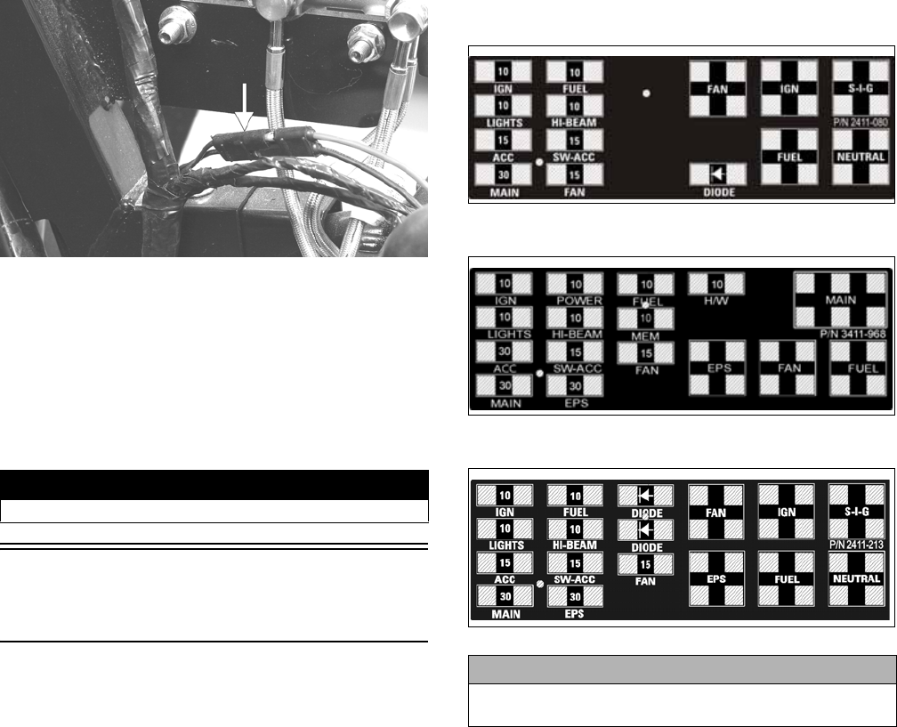
161
2. Connect the red tester lead to the red wire; then con-
nect the black tester lead to the black wire.
PR183A
3. The meter must show less than 1 ohm.
NOTE: If the meter shows more than 1 ohm of resis-
tance, troubleshoot or replace the fan motor.
NOTE: To determine if the fan motor is good, con-
nect the red wire from the fan connector to a 12 volt
battery; then connect the black wire from the fan con-
nector to ground. The fan should operate.
Power Distribution
Module (PDM)
FUSES
The fuses are located in a power distribution module
under the operator’s seat. If there is any type of electrical
system failure, always check the fuses first.
1. Remove a fuse from the power distribution module.
NOTE: To remove the fuse, compress the locking
tabs on either side of the fuse case and lift out.
2. Set the meter selector to the DC Voltage position.
3. Connect the black tester lead to ground.
4. Using the red tester lead, contact each end of the fuse
holder connector terminals individually.
5. The meter must show battery voltage from one side
of the connector terminal ends.
NOTE: Battery voltage will be indicated from only
one side of the fuse holder connector terminal; the
other side will show no voltage.
NOTE: When testing the HI fuse holder, the head-
light OFF/HI/LO switch must be in the HI position;
when testing the LIGHTS fuse holder, the headlight
dimmer switch can be in either the HI or LO position.
NOTE: If the meter shows no battery voltage, trou-
bleshoot the battery, switches, power distribution
module, or the main wiring harness.
XT
2411-080
XTX
3411-968
XTZ
2411-213
1. Set the meter selector to the OHMS position.
2. Connect the red tester lead to one spade end of the
fuse; then connect the black tester lead to the other
spade end.
3. The meter must show less than 1 ohm resistance. If
the meter shows open, replace the fuse.
NOTE: Make sure the fuses are returned to their
proper position according to amperage. Refer to the
amperage listed under each fuse on the power distri-
bution module.
RELAYS
The 4-pin relays are identical plug-in type located on the
power distribution module. Relay function can be
checked by switching relay positions. The 4-pin relays
are interchangeable.
NOTE: The module and wiring harness are not a
serviceable component and must be replaced as an
assembly.
! WARNING
Care should be taken to keep clear of the fan blades.
CAUTION
Always replace a blown fuse with a fuse of the same
type and rating.
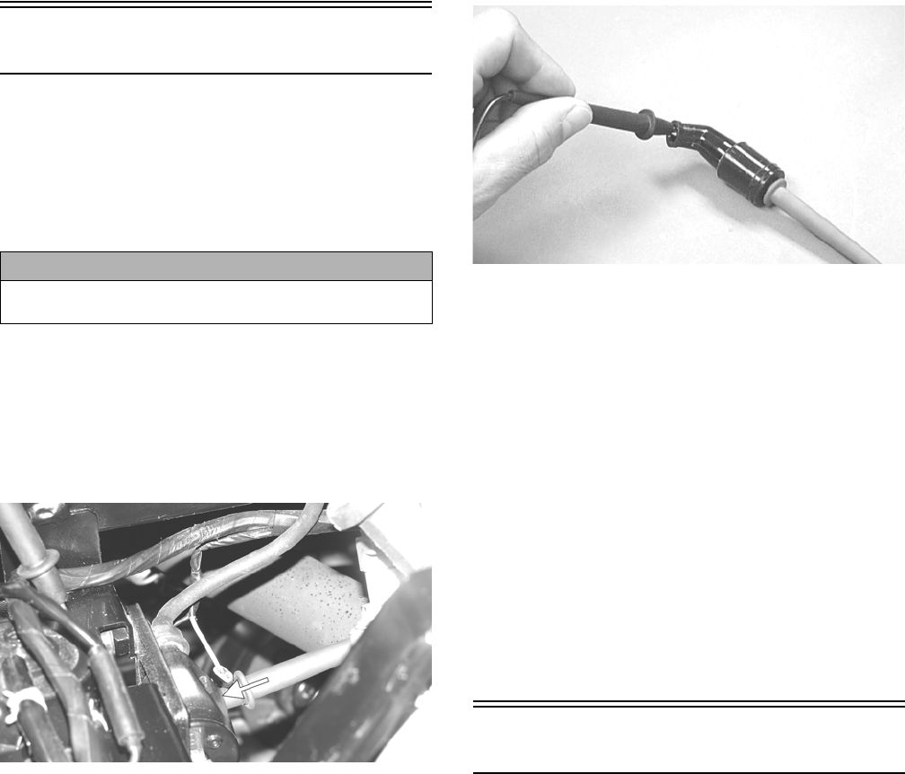
162
Ignition Coil
The ignition coil is mounted on the fuel pump mounting
plate adjacent to the fuel pump.
VOLTAGE (Primary Side)
See Primary Coil in this sub-section.
RESISTANCE
NOTE: For these tests, the meter selector should be
set to the OHMS position.
Primary Winding
1. Connect the red tester lead to the terminal (with the
wire removed); then connect the black tester lead to
ground.
PR278A
2. The meter reading must be within specification.
Secondary Winding
1. Connect the red tester lead to the high tension lead
(with the plug cap removed); then connect the black
tester lead to ground.
2. The meter reading must be within specification.
NOTE: If the meter does not show as specified,
replace ignition coil.
Spark Plug Cap
1. Connect the red tester lead to one end of the cap;
then connect the black tester lead to the other end of
the cap.
AR603D
2. The meter reading must be within specification.
NOTE: If the meter does not show as specified,
replace the spark plug cap.
VOLTAGE
Primary Coil
1. Set the meter selector to the DC Voltage position;
then disconnect the two wires from the coil.
NOTE: The coil is located to the right of the engine
and may be accessed from behind the right-side seat
with the cargo box raised.
2. Connect the red tester lead to the orange wire and the
black tester lead to the blue/white wire (H1) or to ground
(H2).
3. Turn the ignition switch to the ON position. The meter
must show battery voltage.
EFI Sensors/Components
CRANKSHAFT POSITION (CKP)
SENSOR
To test the CKP sensor, see Stator Coil/Crankshaft Posi-
tion (CKP) Sensor in this section.
OXYGEN (O2) SENSOR
The Oxygen Sensor (O2 Sensor) is located in the exhaust pipe.
NOTE: When testing the resistance of the sensor’s
heater, the engine/exhaust pipe must be at room tem-
perature (65-75° F) or inaccurate readings will occur.
1. Open the cargo box; then remove the driver’s seat,
air filter cover, and air filter.
2. Disconnect the sensor.
CAUTION
Always disconnect the battery when performing resis-
tance tests to avoid damaging the multimeter.
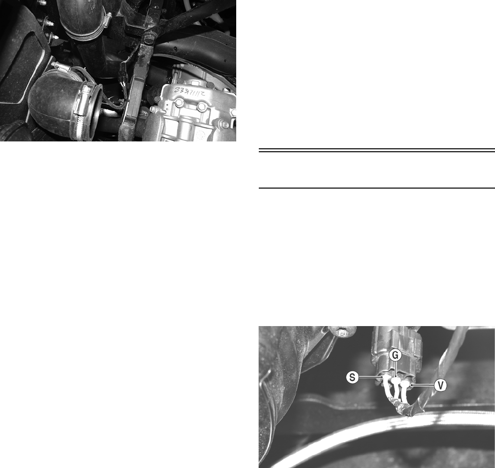
163
PR859
NOTE: For this test, the meter must be in OHMS
position.
3. On the sensor side of connector, connect the black (nega-
tive) test lead to one white wire pin; then connect the red
(positive) test lead to the other white wire pin. Readings
should be between 6.7 and 10.1 ohms.
NOTE: If the meter does not read as specified,
replace the sensor.
MANIFOLD ABSOLUTE PRESSURE
(MAP) SENSOR (550/1000)
1. Disconnect the MAP connector from the pressure
sensor located on the throttle body.
2. Select DC Voltage on the tester and turn the ignition
switch to the ON position.
3. Connect the black tester lead to the black/green wire
and the red tester lead to the orange/blue wire. The
meter should read 4.5-5.5 DC volts. If the meter does
not read as specified, check the ECM connector or
wiring.
4. Connect the MAP to the harness; then using Maxi-
Clips, connect the red tester lead to the brown/white
wire and the black tester lead to the black/green wire.
With the engine running at idle speed, the meter
should read approximately 1.5 DC volts.
NOTE: If the meter does not read as specified,
replace the sensor.
MANIFOLD ABSOLUTE PRESSURE/
INLET AIR TEMPERATURE (MAP/IAT)
SENSOR (700)
NOTE: Preliminary checks may be performed on this
component using the diagnostic mode on the LCD gauge
(see EFI Diagnostic System (XTX) in this section).
1. Disconnect the MAP/IAT connector from the sensor
located on top of the throttle body.
2. Select DC Voltage on the tester and turn the ignition
switch to the ON position.
3. Connect the black tester lead to the black/pink wire and
the red tester lead to the orange/blue wire. The meter
should read 4.5-5.5 DC volts. If the meter does not
read as specified, check the ECM connector or wiring.
4. Connect the MAP/IAT to the harness; then using
MaxiClips, connect the red tester lead to the
brown/white wire and the black tester lead to the
black/pink wire. With the engine running at idle
speed, the meter should read approximately 2.5 DC
volts (MAP sensor signal).
5. Connect the red tester lead to the green/red wire.
With the engine at idle and at room temperature
(approximately 60° F), the meter should read
approximately 2.9 DC volts.
NOTE: If the meter does not read as specified,
replace the sensor.
Speed Sensor
TESTING
NOTE: Prior to testing the speed sensor, inspect the
three-wire connector on the speed sensor for con-
tamination, broken pins, and/or corrosion.
1. Set the meter selector to the DC Voltage position.
2. With appropriate needle adapters on the meter leads,
connect the red tester lead to the voltage lead (V); then
connect the black tester lead to the ground lead (G).
PR279A
3. Turn the ignition switch to the ON position.
4. The meter must show approximately 6 DC volts.
5. Leave the black tester lead connected; then connect the
red tester lead to the signal lead pin (S).
6. Slowly move the vehicle forward or backward; the meter
must show 0 and approximately 6 DC volts alternately.
NOTE: If the sensor tests are within specifications, the
LCD gauge must be replaced.
REPLACING (XT/XTX)
1. Disconnect the three-wire connector from the speed sen-
sor harness or from the speed sensor; then remove the
Allen-head cap screw securing the sensor to the sensor
housing.
2. Remove the sensor from the sensor housing accounting
for an O-ring.
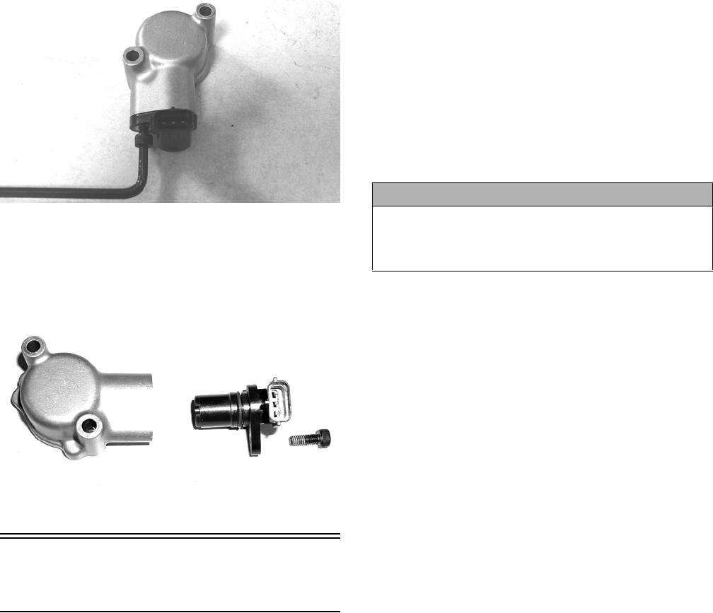
164
CD070
3. Install the new speed sensor into the housing with
new O-ring lightly coated with multi-purpose grease;
then secure the sensor with the Allen-head cap screw
(threads coated with blue Loctite #242). Tighten
securely.
CD071
Electronic Power
Steering (EPS) (XTZ)
The electronic power steering (EPS) system is an elec-
tro-mechanical device that utilizes 12 volt DC power to
drive a motor linked to the steering shaft to assist the
driver when rotating the steering wheel. Driver steering
inputs are detected by a torque-sensing transducer assem-
bly within the EPS housing. These inputs are converted
to electronic signals by the transducer and control cir-
cuitry to tell the motor which way to drive the steering
shaft. When no steering input (pressure on the steering
wheel) is detected, no torque signal is generated, and no
steering assist is provided by the motor.
The EPS system is battery-system powered; therefore,
the battery must be in good condition and fully charged.
Power delivery and overload protection are provided by
an EPS relay and 30-amp fuse, located under the seat in
the Power Distribution Module (PDM).
If a system malfunction occurs, a malfunction code
“P0635” will be displayed on the LCD gauge. Initially,
the gauge will go blank for 30 seconds and the code will
flash: then the gauge will return to normal except the
code will continue to be displayed.
The following is a list of conditions that can generate a
malfunction code. All conditions with the exception of
item 5 are external to the EPS assembly and therefore can
be cleared without replacement of the EPS assembly.
Make sure to thoroughly troubleshoot the entire system
before replacing the EPS assembly.
NOTE: The EPS assembly is not serviceable and no
service parts or parts lists are available. The EPS is
only serviceable as an assembly and must not be dis-
assembled or EPS warranty will be voided.
Malfunction code P0635 will appear if one of the follow-
ing six conditions occur:
1. Battery system power failure:
A. 30 amp EPS fuse blown
B. EPS relay failure
C. EPS voltage less than 8.5 DC volts for more than
two seconds
2. Ignition switch ON for more than five minutes with
the engine not running.
3. Vehicle Speed Signal Malfunction (engine speed
must exceed 2700 RPM for more than 60 seconds to
generate a malfunction code - timer resets if engine
drops below 2700 RPM).
A. Diode defective (open or shorted)
B. Diode not installed
C. Diode installed in reverse
D. Speed sensor defective
E. Speed sensor signal erratic
F. Speed sensor signal present but without engine
speed signal
G. Speed sensor power from LCD gauge interrupted
H. Incorrect LCD gauge installed
4. Engine Speed Signal Malfunction (vehicle speed must
exceed 5 MPH for more than two seconds - timer
resets if speed drops below 5 MPH.
A. No engine speed signal
B. Erratic engine speed signal
5. EPS Control Circuit Malfunction.
The following procedures may be helpful in determining
the source of a malfunction code:
Condition: Ignition Key Switch ON and NO EPS assist
when moving the handlebar. Code “P0635” flashing.
CAUTION
Do not attempt to check resistance of the EPS motor
(2-pin input receptacle). There are internal capacitors
holding a charge that can cause internal damage to an
ohmmeter.
165
NOTE: Prior to troubleshooting below, make sure
that Ignition Key Switch has not been left on with the
engine not started. After five minutes, this will deacti-
vate the EPS and display the malfunction code. Turn
Ignition Key Switch OFF and back to ON to reset and
reactivate the EPS. If code and symptom persists,
continue as follows:
1. Check 30 amp EPS fuse.
2. Check EPS relay (may be switched with any other
4-pin relay on PDM - replace relay if EPS normal
after switching).
3. Disconnect 2-pin connector on the EPS assembly
and connect a volt meter set to DC voltage to the har-
ness (black meter lead to BLK and red meter lead to
ORG/BRN).With the ignition switch to the ON posi-
tion, the meter must read more than 8.5 DC volts (if
correct voltage is not present, check connections and
wiring harness).
Condition: Ignition switch ON and EPS assist normal
when moving handlebar. Code “P0635” flashing.
1. Check for speed sensor signal by disconnecting the
8-pin connector from the EPS assembly and using a
multi-meter set to the DC volt position, connect the
black lead to the PNK/YEL wire and the red lead to
the ORG wire. With the ignition switch turned to the
ON position, slowly move the vehicle forward or
backward. The meter must alternate from 0 DC volts
to approximately 12 DC volts. If meter readings are
not as specified:
A. Check EPS diode for correct installation or open
diode (replace diode or install correctly).
B. Check speed sensor using procedure found in this
section (replace speed sensor/install proper gauge).
2. Check for engine speed signal by disconnecting the
8-pin connector from the EPS assembly and using a
multi-meter set to the AC voltage position, connect
one lead to any BLK wire and the other lead to
YEL/VLT wire. Start the engine and with the engine
idling, the meter should read approximately 7.5 AC
volts. If meter reading is not as specified:
A. Check the wiring harness from EPS to gauge
(YEL/VLT wire - repair wiring).
B. Check the AC generator (see Stator Coil/Crank-
shaft Position (CKP) Sensor in this section). If not
to specifications, replace the stator coil.
If after completing the above checks with normal results and
malfunction code “P0635” persists, the EPS assembly must
be replaced. To replace the EPS assembly, see the Steer-
ing/Frame/Controls section.
Electronic Power
Steering (EPS) (XTX)
The EPS system is an electro-mechanical device that utilizes
12 volt DC power to drive a motor linked to the steering
shaft to assist the driver when rotating the steering wheel.
Driver steering inputs are detected by a torque-sensing
transducer assembly within the EPS housing. These inputs
are converted to electronic signals by the transducer and
control circuitry to tell the motor which way to drive the
steering shaft. When no steering input (pressure on the steer-
ing wheel) is detected, no torque signal is generated, and no
steering assist is provided by the motor.
The EPS system is battery-system powered; therefore, the
battery must be in good condition and fully charged.
Power delivery and overload protection are provided by an
EPS relay and 30-amp fuse, located under the seat in the
Power Distribution Module (PDM). If a system malfunc-
tion occurs, a diagnostic trouble code (DTC) will flash on
the LCD gauge until the condition is corrected, the ignition
key is cycled, or the EPS recovers.
The following is a list of conditions that can generate a
code.
CAUTION
Do not attempt to disassemble the EPS assembly as
there are no serviceable components within the assem-
bly and damage will occur voiding the EPS warranty.
Code Fault Description Fault Condition Possible Cause EPS Fault Recovery Method
C1301 Over Current EPS internal over-current condition
has been detected
Internal EPS Condition Correct EPS condition*
C1302 Excessive Current Error EPS internal current measurement
error has been detected
Internal EPS Condition Correct EPS condition*
C1303 Torque Sensor Range
Fault
EPS internal torque sensor range
condition has been detected
Internal EPS Condition Correct EPS condition*
C1304 Torque Sensor Linearity
Fault
EPS internal torque sensor linearity
condition has been detected
Internal EPS Condition Correct EPS condition*
C1305 Rotor Position Encoder EPS internal rotor position encoder
condition has been detected
Internal EPS Condition Correct EPS condition*
C1306 System Voltage Low EPS battery power low-voltage condi-
tion has been detected
System voltage low (less than 11 VDC at
the EPS). Wire harness issue, faulty volt-
age regulator, weak battery or loose bat-
tery terminals.
EPS will auto-recover when the bat-
tery supply returns to normal
C1307 System Voltage High EPS battery power over-voltage con-
dition has been detected
System voltage high (more than 16 VDC
at the EPS). Wire harness issue, faulty
voltage regulator or loose battery termi-
nals.
EPS will auto-recover when the bat-
tery supply returns to normal
C1308 Temperature Above 110°
C
EPS internal 110° C over-temp condi-
tion has been detected
Clean the EPS housing and cooling fins. EPS will auto-recover when internal
temperature drops below 105° C

166
* After correcting the condition, cycle the key switch
On-Off-On
The following test may help in determining the source of a
code:
NOTE: The EPS assembly is not serviceable and
must not be disassembled or EPS warranty will be
voided. Make sure to thoroughly troubleshoot the
entire system before replacing the EPS assembly.
Condition: Ignition Key Switch ON and NO EPS assist when
moving the steering wheel. Code flashing.
NOTE: Prior to troubleshooting below, make sure the
Ignition Key Switch has not been left on with the engine
not started. After five minutes, this will deactivate the EPS
and display the code. Turn the Ignition Key Switch OFF
and back to ON to reset and reactivate the EPS. If code
and symptom persists, continue as follows:
1. Check 30-amp EPS fuse.
2. Check EPS relay (may be switched with any other 4-pin
relay on PDM - replace relay if EPS normal after switch-
ing).
C1309 Temperature Above 120°
C
EPS internal 120° C over-temp condi-
tion has been detected
Clean the EPS housing and cooling fins. EPS will auto-recover when internal
temperature drops below 115° C
C1310 Vehicle Speed High Vehicle speed signal received by the
EPS exceeds the maximum speed
specification
Intermittent main harness wires, defective
speed-sensor, or intermittent speed sen-
sor wires.
EPS will auto-recover when the
vehicle speed signal drops below
the maximum speed specification
C1311 Vehicle Speed Low Vehicle speed signal received by the
EPS is zero or missing
Broken main harness wires, defective
speed-sensor, or broken speed sensor
wires.
EPS will auto-recover when the
vehicle speed signal returns to nor-
mal
C1312 Vehicle Speed Faulty Vehicle speed CAN signal received by
the EPS incorrect or missing
Broken main harness CAN wires, defec-
tive speed-sensor, or broken speed sen-
sor wires.
EPS will auto-recover when the
vehicle speed signal returns to nor-
mal
C1313 Engine RPM High Engine RPM signal received by the
EPS exceeds the maximum RPM
specification
Intermittent main harness RPM wires,
intermittent voltage regulator, intermittent
ACG stator wires.
EPS will auto-recover when engine
RPM signal drops below the maxi-
mum RPM specification
C1314 Engine RPM Low Engine RPM signal received by the
EPS suddenly dropped below 500
RPM
Handlebar switch in the "OFF" position,
broken main harness RPM wires, defect
voltage regulator, broken ACG stator
wires.
EPS will auto-recover when engine
RPM signal returns to normal
C1315 Engine RPM Faulty Engine RPM CAN signal received by
the EPS incorrect or missing
Broken main harness CAN wires or
defective ECM.
EPS will auto-recover when engine
RPM signal returns to normal
C1316 EEPROM Error EPS internal memory error has been
detected
Internal EPS condition Correct EPS condition*
C1317 CAN Bus Error The EPS has lost CAN communica-
tion with the EFI ECM
Broken CAN wires in the main harness.
EFI ECM connector has been discon-
nected.
Correct EPS condition*
C1318 Internal CRC Error EPS internal CRC calculation condi-
tion has been detected
EPS reflash has failed. Battery power
was lost, or the keyswitch was turned off,
during EPS reflash programming.
EPS must be reprogrammed
C1319 Boot Counter Exceeded EPS internal application code condi-
tion has been detected
Intermittent power has prevented a suc-
cessful application code launch.
Correct EPS power condition*
C1320 Incorrect Vehicle
Speed-to-RPM Ratio
Vehicle speed signal received by the
EPS exceeds 10 MPH, but the engine
RPM signal less than 500 RPM
Intermittent or broken main harness RPM
wires, intermittent voltage regulator, inter-
mittent or broken ACG stator wires.
Correct EPS condition*
C1321 Vehicle Speed Erratic Vehicle speed signal received by the
EPS changing at an unrealistic rate
Intermittent main harness, intermittent
speed sensor, dirty speed senor or trigger
wheel.
Correct EPS vehicle speed signal
condition*
C1322 Engine RPM Lost Engine RPM signal received by the
EPS exceeds 500 RPM and then is
zero or missing
Handlebar switch in the "OFF" position,
broken main harness RPM wires, defect
voltage regulator, broken ACG stator
wires.
EPS will auto-recover when engine
RPM signal returns to normal
C1323 "EPS OFF" Gauge Dis-
play
Battery power has been applied to the
EPS for more than 5-minutes, but no
engine RPM signal has been
detected
The EPS has been automatically dis-
abled, after 5-minutes of inactivity, to con-
serve battery power.
EPS will auto-recover when engine
is started or the keyswitch is cycled
On-Off-On
C1324 Loss of CAN communica-
tion with EPS unit
The gauge has lost CAN communica-
tion with the EPS
Broken CAN wires in the main harness or
disconnected EPS. This is not an EPS
generated DTC; gauge DTC display only.
Gauge DTC display will clear when
the EPS-to-gauge CAN communica-
tion is restored.
C1325 Dual Loss EPS loss of both the vehicle speed
and the engine RPM signals has been
detected
Handlebar switch in the "OFF" position,
the engine stalled (keyswitch "ON"), bro-
ken harness wires, loss of CAN data sig-
nal.
EPS will auto-recover when either
the vehicle speed or engine RPM
signal is restored.
C1326 Rotor Position Encoder EPS internal rotor position encoder
variance condition has been detected
Internal EPS Condition Correct EPS condition*
C1327 Voltage Converter Error
(Low)
EPS internal voltage converter
low-voltage condition has been
detected
Internal EPS Condition Correct EPS condition*
C1328 Voltage Converter Error
(High)
EPS internal voltage converter
over-voltage condition has been
detected
Internal EPS Condition Correct EPS condition*
C1329 Internal Data Error EPS internal preloaded data condition
has been detected
Internal EPS Condition EPS must be reprogrammed
Code Fault Description Fault Condition Possible Cause EPS Fault Recovery Method
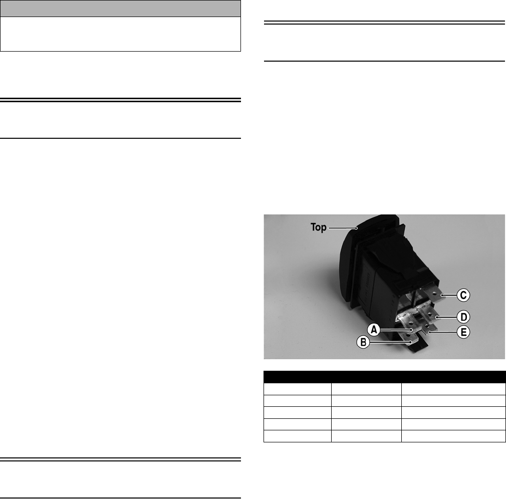
167
3. Disconnect 2-pin connector on the EPS assembly and
connect a volt meter set to DC voltage to the harness
(black meter lead to BLK and red meter lead to
ORG/BRN).With the ignition switch to the ON position,
the meter must read more than 8.5 DC volts (if correct
voltage is not present, check connections and wiring har-
ness - if correct voltage is present, replace EPS assembly -
see Steering/Frame/Controls).
If after completing the above check with normal results and a
code persists, the EPS assembly must be replaced (see Steer-
ing/Frame/Controls).
Ignition Switch
To access the ignition switch, dash switches, front acces-
sory connectors, and front switched accessory connector,
the dash must be unfastened and slid to the rear.
VOLTAGE
1. Set the meter selector to the DC Voltage position.
2. Connect the red meter lead to the red wire; then con-
nect the black meter lead to ground.
3. Meter must show battery voltage.
NOTE: If the meter shows no battery voltage, trou-
bleshoot the main 30 amp fuse, the battery, or the
main wiring harness.
4. Connect the red meter lead to the red/black wire;
then with the black lead grounded, turn the ignition
switch to the ON position. The meter must show bat-
tery voltage.
5. Connect the red meter lead to the yellow/green wire;
then with the black lead grounded, turn the ignition
switch to the START position. The starter should
engage and the meter must show battery voltage.
NOTE: When the starter is engaged, battery voltage
will be approximately 10.5 DC volts.
Headlight Switch
VOLTAGE
1. Connect the red meter lead to the gray wire; then
connect the black meter lead to the black wire.
2. Turn the ignition switch to the ON position. The
meter must show battery voltage.
NOTE: If the meter does not show battery voltage,
troubleshoot the LIGHTS fuse on the power distribu-
tion module, the ignition switch, or the main harness.
3. Connect the red meter lead to the yellow wire; then
select the high beam position on the headlight
switch. The meter must show battery voltage.
4. Connect the red meter lead to either of the two white
wires; then select the low beam position on the head-
light switch. The meter must show battery voltage.
NOTE: The battery voltage will show lower in steps
3 and 4 due to electrical loading of the headlights.
Drive Select Switch
RESISTANCE
1. Remove the switch assembly from the dash; then dis-
connect the harness from the switch.
NOTE: The switch can be removed from the dash
using a thin, flat pry bar or suitable putty knife. It is
not necessary to remove the dash to remove the
switch.
2. Using an ohmmeter, the following readings must be
observed.
PR566A
VOLTAGE
NOTE: Voltage tests must be made with the switch
and the actuator connected. The meter can be con-
nected at the actuator connector using a break-out
harness or MaxiClips.
1. Connect the black tester lead to the black wire; then
turn the ignition switch to the ON position.
2. Select the DC Volts position on the tester and
observe the meter readings for each of the three
switch positions.
CAUTION
Do not attempt to check resistance of the EPS motor (2-pin
input receptacle). There are internal capacitors holding a
charge that can cause internal damage to an ohmmeter.
2WD 4WD DIFFERENTIAL LOCK
A to D <1 ohm A to D <1 ohm A to D <1 ohm
C to E <1 ohm C to E <1 ohm C to E <1 ohm
A to B Open A to B <1 ohm A to B <1 ohm
A to C Open A to C Open A to C <1 ohm
A to E Open A to B <1 ohm A to C <1 ohm

168
NOTE: If the meter does not show voltages accord-
ing to the chart, make sure the front drive actuator is
plugged in; then troubleshoot the switch, ignition
fuses, battery connections, or wiring harness.
Reverse Override Switch
VOLTAGE
NOTE: To perform the following tests, the ignition
switch must be in the ON position and the transmis-
sion shifted into reverse gear.
1. Connect the red meter lead to the black/blue wire and the
black meter lead to a suitable ground; then select 2WD
on the drive select switch. The meter must show approx-
imately 1.5 DC volts.
2. Depress the reverse override switch. The meter showing
should not change from step 1.
3. Select 4WD on the drive select switch. The meter must
show approximately 5 DC volts.
4. Depress the reverse override switch. The meter must
show approximately 1.5 DC volts.
5. Connect the red meter lead to the red/yellow wire. The
meter must show approximately 1.5 DC volts. Depress
the reverse override switch. The meter must show
approximately 1.5 DC volts.
6. Connect the red meter lead to the red/green wire. The
meter should show 0 DC volts.
7. Depress the reverse override switch. The meter must
show approximately 5 DC volts.
Front Drive Actuator
NOTE: With the engine stopped and the ignition switch
in the ON position, a momentary “whirring” sound must
be noticeable each time the drive select switch is moved
to 2WD and 4WD. Test the switch, 30 amp fuse, and wiring
connections prior to testing the actuator.
NOTE: The differential must be in the unlocked position
for this procedure.
VOLTAGE
1. Locate the 4-wire connector for the front drive selector
actuator on the frame to the right of the differential; then
connect the red meter lead to the orange wire using a
MaxiClip.
PR293
2.
Connect the black lead to the black wire using a Maxi-
Clip; then select 2WD on the drive select switch.
PR295
NOTE: The black tester lead can remain connected
to the black wire for the remaining tests.
3. Turn the ignition switch to the ON position. The
meter must show battery voltage.
NOTE: If battery voltage is not shown, troubleshoot
the 10 amp ignition (IGN) fuse on the power distribu-
tion module, the ignition switch, or the main wiring
harness.
4. Connect the red meter lead to the white/red wire. The
meter must show battery voltage.
5. Select 4WD on the drive select switch. The meter
must show 0 DC volts.
6. Connect the red meter lead to the white/orange wire.
The meter must show battery voltage.
7. Engage the differential lock. The meter must show 0
DC volts.
NOTE: If the meter does not show 0 DC volts, rock
the vehicle to help engage the differential lock; then
troubleshoot the drive select switch.
Stator Coil/Crankshaft
Position (CKP) Sensor
VOLTAGE (AC Generator -
Regulated Output)
1. Set the meter selector to the DC Voltage position.
WIRE COLOR 2WD 4WD DIFFERENTIAL LOCK
Black to Orange 12.0 DC Volts 12.0 DC Volts 12.0 DC Volts
Black to
White/Green
11.5 DC Volts 0 DC Volts 0 DC Volts
Black to
White/Red
11.5 DC Volts 11.5 DC Volts 0 DC Volts
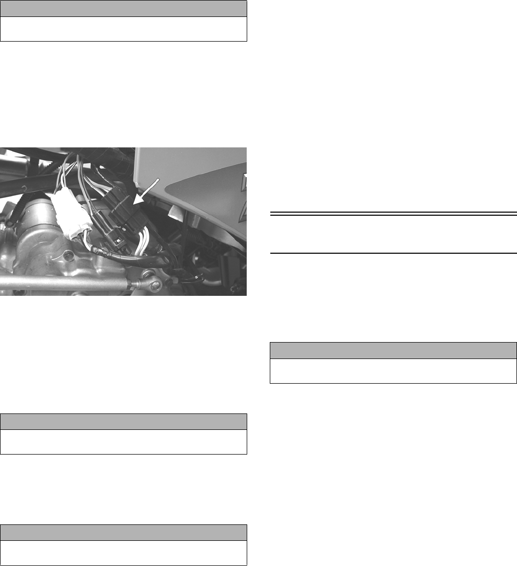
169
2. Connect the red tester lead to the positive battery
post; then connect the black tester lead to the nega-
tive battery post.
3. With the engine running at a constant 5000 RPM
(with the headlights on), the meter must show
14-15.5 DC volts.
NOTE: If voltage is lower than specified, test AC
Generator - No Load.
VOLTAGE (AC Generator - No
Load)
The connector is the black three-pin one on the left side
above the shift lever.
FI083B
NOTE: Test the connector coming from the engine.
1. Set the meter selector to the AC Voltage position.
2. Test between the three yellow wires (H1) or the three
black wires (H2) for a total of three tests.
3. With the engine running at a constant 5000 RPM, all
wire tests must be within specification.
NOTE: If both stator coil tests failed, check all con-
nections, etc., and test again. If no voltage is present,
replace the stator assembly.
RESISTANCE (AC Generator)
1. Set the meter selector to OHMS position.
2. Test between the three yellow wires (H1) or the three
black wires (H2) for a total of three tests.
3. The meter reading must be within specification.
RESISTANCE
(Crankshaft Position Sensor)
1. Set the meter selector to the OHMS position.
2. Connect the red tester lead to the blue wire
(XT/XTZ) or brown wire (XTX); then connect the
black tester lead to the green wire (XT/XTZ) or
white wire (XTX). The meter reading must be within
specification.
AC VOLTAGE
NOTE: The battery must be at full charge for these
tests.
Crankshaft Position Sensor
1. Set the meter selector to the AC Voltage position.
2. Connect the red tester lead to the blue wire
(XT/XTZ) or brown wire (XTX); then connect the
black tester lead to the green wire (XT/XTZ) or
white wire (XTX).
3. Crank the engine over using the electric starter.
4. The meter reading must be within specification.
Starter Motor
NOTE: The starter motor is not a serviceable com-
ponent. If the motor is defective, it must be replaced.
REMOVING
1. Disconnect the battery.
2. Remove the nut securing the positive cable to the
starter motor; then remove the cable from the starter.
3. Remove the two cap screws securing the starter
motor with ground wires to the crankcase; then
remove the starter motor. Account for the wiring
forms and an O-ring.
INSTALLING
1. Apply a small amount of grease to the O-ring seal on
the starter motor; then install the starter into the
crankcase. Secure with two machine screws and wir-
ing forms.
2. Secure the positive cable to the starter motor with the
nut.
3. Connect the battery.
TESTING VOLTAGE
Perform this test on the starter motor positive terminal.
To access the terminal, slide the boot away.
CAUTION
Do not run the engine at high RPM for more than 10 sec-
onds.
CAUTION
Do not run the engine at high RPM for more than 10 sec-
onds.
CAUTION
Always disconnect the battery when performing resis-
tance tests to avoid damaging the multimeter.
CAUTION
Always disconnect the negative battery cable from the
battery first; then disconnect the positive cable.
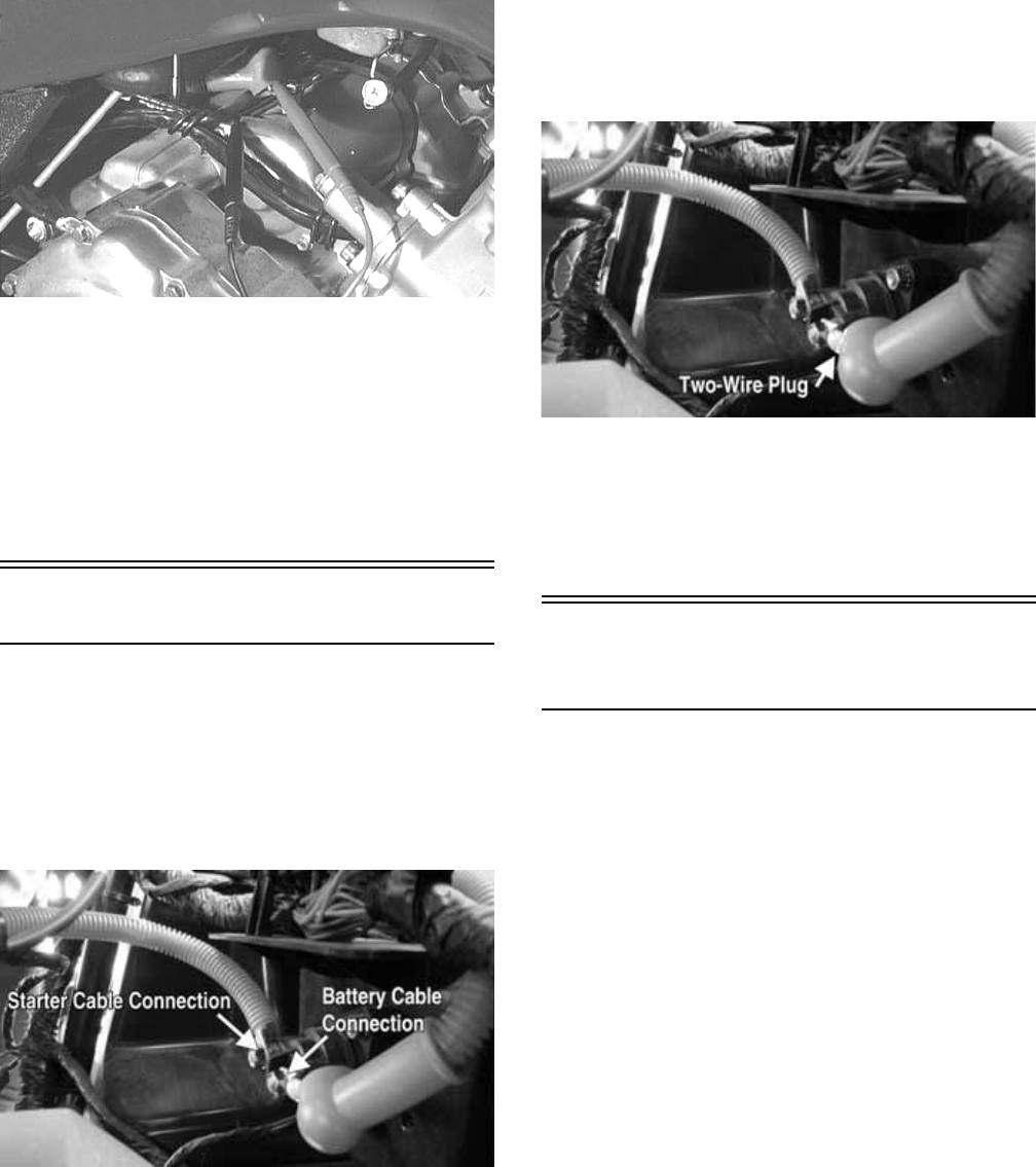
170
NOTE: The ignition switch must be in the ON posi-
tion, and the shift lever in the NEUTRAL position.
1. Set the meter selector to the DC Voltage position.
2. Connect the red tester lead to the starter terminal;
then connect the black tester lead to ground.
3. With the starter button depressed, the meter must
show battery voltage and the starter motor should
operate.
AR607D
NOTE: If the meter showed battery voltage but the
starter motor did not operate or operated slowly,
inspect battery voltage (at the battery), starter motor
condition, and/or ground connections.
NOTE: If the meter showed no battery voltage,
inspect the main fuse, ground connections, starter
motor lead, battery voltage (at the battery), starter
relay, or the neutral start relay.
Starter Relay
1. Remove the seats and center console; then using the
multimeter set to the DC Voltage position, check the
relay as follows.
2. Connect the red tester lead to the positive battery
cable connection; then connect the black tester lead
to the starter cable connection. The meter must show
battery voltage.
PR841A
NOTE: Make sure the ignition switch is in the ON
position, transmission in neutral, and parking brake
set.
3. Depress the starter button while observing the multi-
meter. The multimeter should drop to 0 volts and a
“click” should be heard from the relay.
NOTE: If a “click” is heard and more than one volt is
indicated by the multimeter, replace the starter relay.
If no “click” is heard and the multimeter continues to
indicate battery voltage, proceed to step 4.
4. Disconnect the two-wire plug from the starter relay;
then connect the red tester lead to the green wire and
the black tester lead to the black wire.
PR841B
5. Depress the starter button and observe the multime-
ter.
NOTE: If battery voltage is indicated, replace the
starter relay. If no voltage is indicated, proceed to
Neutral Start Relay check.
Electronic Control Unit
(ECM)
The ECM is located beneath the seat near the battery.
NOTE: The ECM is not a serviceable component. If
the unit is defective, it must be replaced.
The ECM is rarely the cause for electrical problems; how-
ever, if the ECM is suspected, substitute another ECM to ver-
ify the suspected one is defective.
This EFI system has a built-in feature that will only allow an
ECM of the same part number to be used in these models. Do
not attempt to substitute an ECM from a different model as
the system will not allow it to start.
Error codes can be cleared by following the procedures
located in the ECM Error Codes sub-section in this section.

171
Regulator/Rectifier
The regulator/rectifier is located under the operator’s seat
next to the battery. Try to verify all other charging system
components before the regulator/rectifier is replaced.
TESTING
1. Start engine and warm up to normal operating tem-
perature; then connect a multimeter (set at the DC
Voltage position) to the battery as follows.
2. Connect the red tester lead to the positive battery
post and the black tester lead to the negative battery
post.
3. Slowly increase RPM. The voltage should increase
with the engine RPM to a maximum of 15.5 DC
volts.
NOTE: If voltage rises above 15.5 DC volts, the reg-
ulator is faulty or a battery connection is loose or cor-
roded. Clean and tighten battery connections or
replace the regulator/rectifier. If voltage does not rise,
see Stator Coil/Crankshaft Position (CKP) Sensor -
Voltage in this section. If charging coil voltage is nor-
mal, replace the regulator/rectifier.
Headlights
The connectors are the four 2-prong ones secured to the
headlight bulbs (two on each side).
VOLTAGE
NOTE: The low beams are the outside bulbs (black
and white wires) and the high beams are the inside
bulbs (yellow and black wires). Always connect the
black tester lead to the black wires. The ignition
switch must be in the ON position.
1. Set the meter selector to the DC Voltage position.
2. Set the light switch to the correct position for the
affected light; then connect the black tester lead to
the black wire using a MaxiClip.
3. Connect the red tester lead to the yellow wire (high
beam) or white wire (low beam) using a MaxiClip.
The meter must show battery voltage.
NOTE: If battery voltage is not shown in any test,
inspect the LIGHTS fuse on the power distribution
module, headlight switch, ignition switch, switch con-
nectors, or wiring harness.
Taillight-Brakelight
VOLTAGE (Taillight)
NOTE: Perform this test at the socket end of the tail-
light-brakelight harness (pigtail). The ignition switch
must be in the ON position and either high beam or
low beam selected on the light switch.
1. Set the meter selector to the DC Voltage position.
2. Connect the black tester lead to the black wire; then
connect the red tester lead to the white wire. The
meter should show battery voltage.
3. With the ignition key in the LIGHTS position, the
meter must show battery voltage.
NOTE: If battery voltage is not shown and the head-
lights are illuminated, inspect the three-wire connec-
tor in the left-rear canopy tube at the juncture of the
canopy tube and lower frame. If battery voltage is
shown on the meter, replace the bulb.
VOLTAGE (Brakelight)
NOTE: Perform this test at the socket end of the tail-
light/brakelight harness (pigtail). The ignition switch
must be in the ON position.
1. Set the meter selector to the DC Voltage position.
2. Connect the red tester lead to the red/blue wire; then
connect the black tester lead to the black wire.
3. With the brake applied, the meter must show battery
voltage.
NOTE: If the meter shows no voltage, inspect the 10
amp ignition (IGN) fuse, brakelight switch, wiring har-
ness, or connectors.
Ignition Timing
The ignition timing cannot be adjusted; however, verify-
ing ignition timing can aid in troubleshooting other com-
ponents. To verify ignition timing, use the following
procedure.
NOTE: To check ignition timing, the seats and cen-
ter console must be removed.
1. Attach the Timing Light to the spark plug high ten-
sion lead; then remove the timing inspection plug
from the left-side crankcase cover.
2. Start the engine and using the RPM function on the
speedometer/tachometer, run at 1500 RPM; ignition
timing should be 10° BTDC.
3. Install the timing inspection plug.
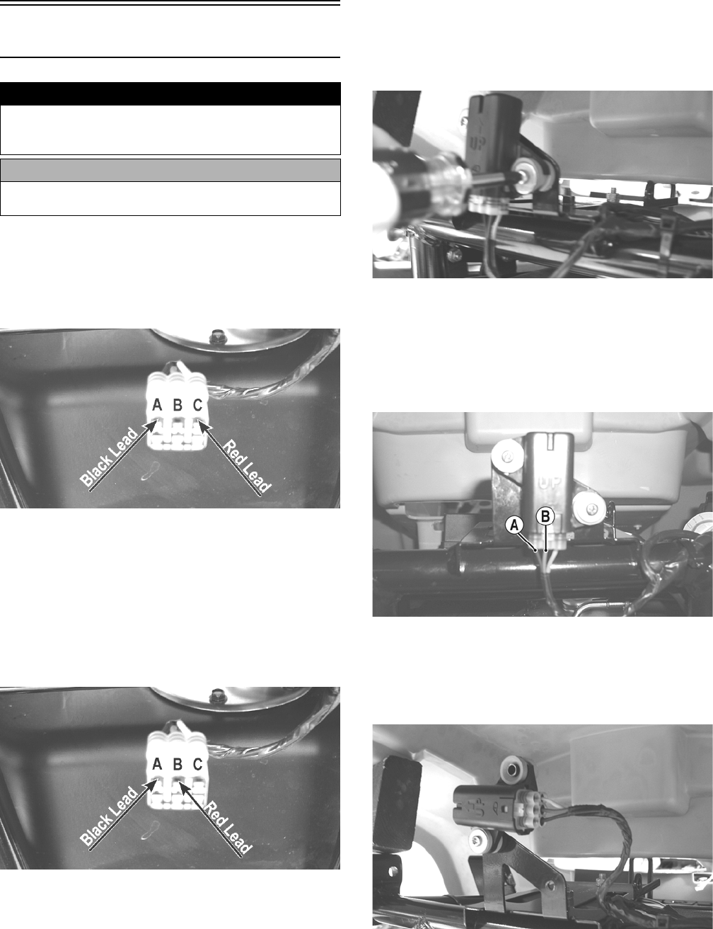
172
If ignition timing cannot be verified, the rotor may be
damaged, the key may be sheared, the trigger coil bracket
may be bent or damaged, or the ECM may be faulty.
Tilt Sensor
SUPPLY VOLTAGE
1. Disconnect the three-wire connector from the sensor;
then select DC Voltage on the multimeter and connect
the red tester lead to the orange wire (C) and the black
tester lead to the black wire (A).
CD706A
2. Turn the ignition switch to the ON position. The multi-
meter should read battery voltage. If battery voltage is
not indicated, check the 30-amp fuse, wiring harness,
or the ignition switch.
3. Remove the red tester lead and connect to the
blue/brown wire (B). The multimeter should read
approximately 2.5 DC volts. If the specified voltage is
not indicated, check wire connections at the ECM or
substitute another ECM to verify the test.
CD706B
OUTPUT VOLTAGE
NOTE: Needle adapters will be required on the mul-
timeter leads as the following tests are made with the
sensor connected.
1. Connect the three-wire plug to the sensor; then
remove the right-side mounting screw securing the
sensor to the rear frame.
CD707
2. Install the needle adapters to the multimeter leads;
then select DC Voltage on the multimeter.
3. Connect the red tester lead to the blue/brown wire
(B) and the black tester lead to the black/yellow wire
(A); then turn the ignition switch ON and observe the
meter. The meter should read 0.8-3.0 DC volts.
CD705B
4. Tilt the sensor 60° or more to the left and right
observing the meter. The meter should read 4.0-8.0
DC volts after approximately one second in the tilted
position. If the meter readings are not as specified,
the tilt sensor is defective.
CD709
! WARNING
Incorrect installation of the tilt sensor could cause sud-
den loss of engine power which could result in loss of
vehicle control resulting in injury or death.
CAUTION
Do not drop the tilt sensor as shock can damage the
internal mechanism.
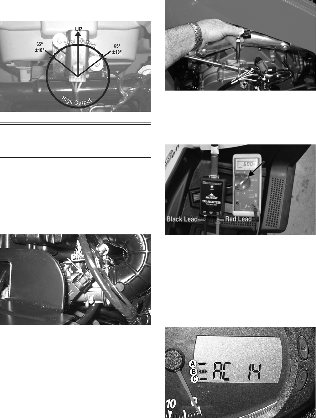
173
NOTE: When replacing the sensor after testing,
make sure the arrow marking is directed up.
CD705A
Throttle Position Sensor
(TPS)
NOTE: On the XTX, preliminary checks may be per-
formed on this component using the diagnostic mode
on the LCD gauge (see EFI Diagnostic System in this
section).
TESTING (XTX)
1. Remove the seats and center console; then discon-
nect the three-wire TPS connector plug.
PR533A
NOTE: Prior to testing the TPS, inspect the
three-wire plug connector on the main harness and
the three-pin plug on the TPS for contamination, bro-
ken pins, and/or corrosion.
NOTE: If the vehicle is in warranty, removing or
adjusting the TPS will void warranty. If the TPS is
tested out of specification, the throttle body must be
replaced. If the vehicle is out of warranty, the TPS
may be adjusted.
2. Connect the TPS Multi-Analyzer Harness connector
#8 to the TPS; then connect the harness to the TPS
Analyzer Tool.
FI672
3. Using a multimeter, connect the black tester lead to
the white socket (VAR) on the analyzer and the red
tester lead to the red socket (+5V); then select the
DC Voltage position. With the vehicle off, the gauge
should read 0.58-0.62 and at Wide-Open Throttle it
should read up to approximately 3.7.
FI676A
TESTING (XT/XTZ)
1. Connect the main harness to the TPS.
2. Locate the diagnostic plug under the driver’s seat
next to the PDM; then install the Test Plug from Test
Plug/Error Code List onto the plug.
3. Turn the ignition switch to the ON position and note
the position of the TPS indicator icon (A, B, or C);
then adjust the TPS until the TPS icon appears in the
center position (B).
PR541B
4. Cycle the accelerator pedal to approximately half throt-
tle six times; then return the accelerator pedal to idle.
The display should return to the center position (B).
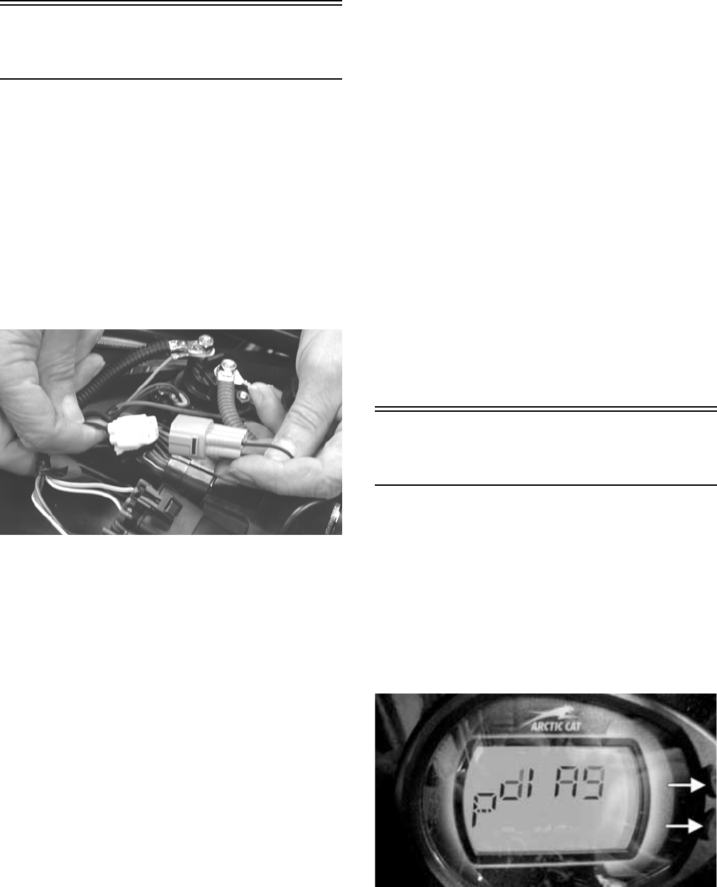
174
4. Remove the test plug.
ECM Error Codes
(XT/XTZ)
If a sensor fails or an out-of-tolerance signal is sensed by
the ECM, an error code will be generated by the ECM.
This will result in the analog needle swinging full scale.
The EFI icon will flash.
To read the error code(s), use the following procedure.
1. Make sure the ignition switch is in the OFF position;
then remove the seats.
2. Locate the diagnostic plug next to the PDM; then
remove the black rubber cap.
3. Connect the Test Plug from Test Plug/Error Code
List to the diagnostic plug.
ATV-112
4. Turn the ignition switch to the ON position and read
the error code on the LCD. Refer to the following Code
List to identify the specific problem area.
Code List
NOTE: Each of the following numerical codes will
have a two-letter prefix. A prefix of AC (Active Code)
or SC (Stored Code) will be displayed. Always correct
and clear Active Codes before clearing Stored Codes.
• 00 = No Fault Detected (active code only)
• 12 = CKP (Crankshaft Position) Sensor*
• 13 = APS (Air Pressure Sensor) - H1
• 13 = MAP (Manifold Absolute Pressure) Sensor - H2
• 14 = TPS (Throttle Position Sensor)
• 15 = ECT (Engine Coolant Temperature) Sensor
• 16 = Speed Sensor
• 21 = IAT (Inlet Air Temperature) Sensor
• 23 = Tilt Sensor*
• 24 = Ignition Coil #1*
• 26 = Ignition Coil #2* - H2
• 32 = Fuel Injector #1*
• 34 = Fuel Injector #2* - H2
• 40 = ISC (Idle Speed Control) Valve
• 41 = Fuel Pump Relay*
• 60 = Cooling Fan Relay
•95 =Sensor Power
• 96 = Incorrect ECM*
• 97 = ECM Memory Power (constant battery power)
• 98 = ECM to Gauge Comm Link - H2
• 99 = Start/Run Not Possible (active code only)
*Will initiate code 99.
After all stored codes are cleared, clear the error code(s)
using the following procedure.
NOTE: The ignition switch should be in the OFF
position.
1. With the test plug connected to the diagnostic plug and
the drive select switch in the 4WD position, hold the
reverse override switch down and turn the ignition
switch to the ON position.
2. After ten seconds, release the reverse override switch
and turn the ignition switch to the OFF position; then
turn the ignition switch to the ON position. The display
should read AC00 (no fault detected).
NOTE: If the LCD still displays an error code, con-
tinue troubleshooting the appropriate component.
3. Disconnect the test plug; then install the black rubber cap.
4. Install the seats making sure they lock securely in place.
EFI Diagnostic System
(XTX)
DIGITAL GAUGE
The digital gauge can be used as a diagnostic tool for
many of the DTC’s displayed. To place the gauge into the
diagnostic mode, use the following procedure.
1. Turn the ignition switch ON.
2. Depress and hold both Mode and Set buttons
together for approximately 10 seconds after which
the letters “dIAg” will appear on the LCD momen-
tarily followed by COOL.
EFI002A
NOTE: The display on the gauge will display in SAE
(speedometer in MPH mode) or Metric (speedometer
in km/h mode), For example to read temperature in
degrees Celsius, select km/h mode on the gauge or
to read Fahrenheit, select MPH mode.
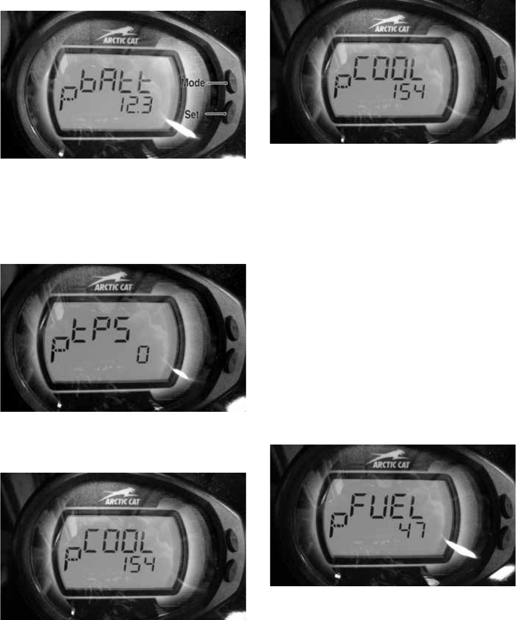
175
3. Cycle the display by depressing either the Set or
Mode button to step to the desired function.
EFI004
NOTE: The gauge can be utilized dynamically
(engine running/vehicle moving) or statically
(engine/vehicle stopped).
Examples of Static checks: Battery voltage, fuel
gauge/sensor, and TPS (0% @ closed throttle, 95-100%
@ WOT).
EFI007
Examples of Dynamic checks: Battery charging, coolant
temperature including fans ON/OFF (see below),
MAP/IAT, tachometer, and speedometer signal.
EFI003
*Fan Schedule: Fan ON @ 185° F, OFF @ 175° F.
*High Temperature REV Limiter 5000 RPM @ 230° F.
*Thermostat opens @ approximately 180° F noted by a 2-5 degree drop
momentarily.
Coolant (COOL) Diagnostic Mode
EFI 003
Display: Engine coolant temperature as measured by the
ECT sensor.
DTC: P0116, P0117, P0118, P0119
Usage: Monitor coolant temperature to verify the following.
1. ECT sensor signal
2. High Temperature indicator (on @ 230° F.)
3. Thermostat opening @ approximately 180° F, indi-
cated by a momentary drop or pause in the rising
temperature reading.
4. Fan ON @ 185° F, OFF @ 175° F.
A. fan motor
B. fan relay
C. fan fuse
D. wiring connections
5. High Temperature Rev Limiter 5000 RPM @ 230° F.
Fuel Sensor (FUEL) Diagnostic
Mode
EFI010
Display: Fuel level signal from the fuel level sensor
(measured in ohms).
DTC: C1400
Usage: Check output of the fuel level sensor
1. Full fuel is indicated by a reading of 0-25 ohms
2. Empty is indicated by a reading of 98-100 ohms.
* 110-500 ohms, suspect the fuel level sensor or wiring
* 0-100 ohms but no fuel gauge indication, suspect the fuel gauge
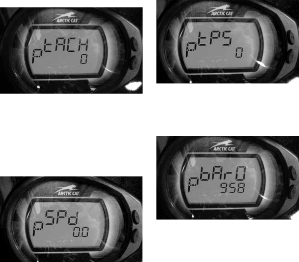
176
Tachometer (tACH) Diagnostic
Mode
EFI009
Display: Engine RPM
DTC: P0336, P0337, P0339
Usage: Verify engine speed signal from the following.
1. CKP (crankshaft position) sensor to ECM
2. ECM (CAN) signal to gauge (tachometer)
3. ECM (CAN) signal to EPS
Speed (SPd) Diagnostic Mode
EFI008
Display: vehicle speed signal.
DTC: P0500
Usage: verify speedometer sensor signal from the follow-
ing.
1. Speed sensor to ECM.
2. ECM (CAN) signal to gauge (speedometer/odome-
ter).
3. ECM (CAN) signal to EPS unit.
TPS (tPS) Diagnostic Mode
EFI007
Display: % of TPS (0% closed, 95-100% WOT).
DTC: P0121, P0122, P0123
Usage: Verify TPS signal and adjust throttle cable.
MAP (bArO) Diagnostic Mode
EFI006
Display: MAP in millibars (1013 millibar = 29.92 in.
mercury).
DTC: P0107, P0108
Usage: Verify barometric pressure signal correct.
Note: Local barometric pressure is given in in./Hg
(Inches of Mercury). 34 millibars are equal to 1 inch of
mercury. Example: (Gauge reading in the BARO mode
= 974 millibars, thus 974/34 = 28.64 in./Hg). Second
example: (Local barometer reading is 29.87 in./Hg,
therefore 29.87 X 34 = 1015 millibars) The gauge
should be reading very close to 1015.
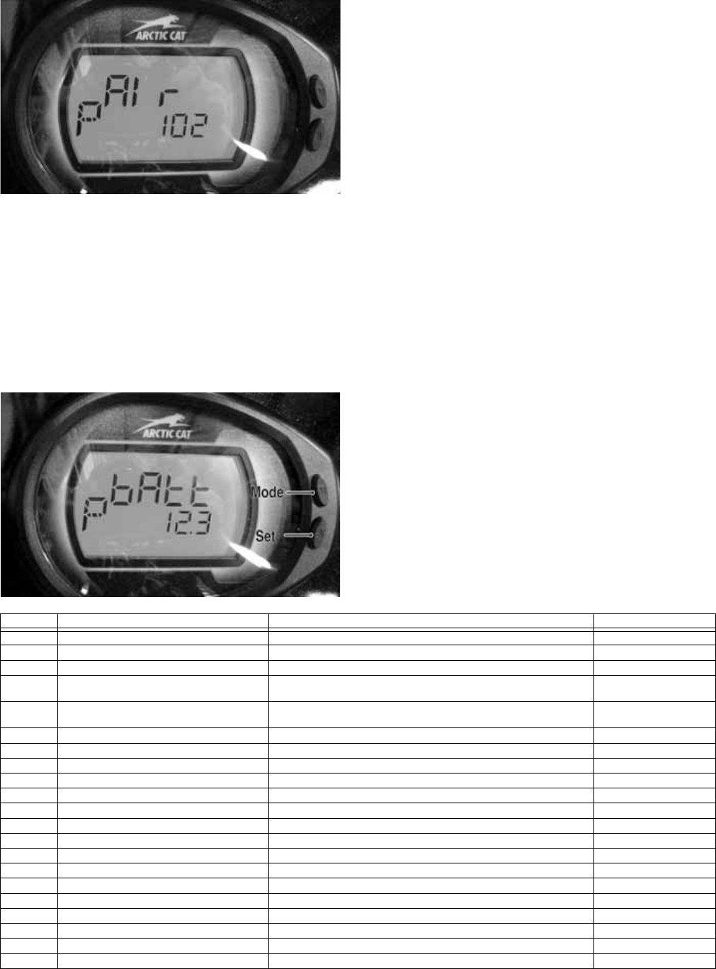
177
Inlet Air Temperature (AIr)
Diagnostic Mode
EFI005
Display: Inlet air temperature in Fahrenheit or Celsius.
DTC: P0112, P0113, P0114
Usage: Verify correct output of IAT sensor.
NOTE: After engine has been running, IAT readings
will be higher than outside air temperature due to
engine and engine compartment heat as well as
intake manifold heating.
Battery (bAtt) Diagnostic Mode
EFI004
Display: System DC voltage.
DTC: P0562, P0563, P2531, P2532
Usage: Verify system voltage under following conditions.
1. Battery voltage with engine and accessories off
(>12.2 VDC for fully charged).
2. Battery voltage with engine running (charging = 13.8
VDC or greater).
3. Battery voltage with electrical accessories operating,
engine idling (13.5 VDC or greater).
4. Battery voltage starter cranking (10.5-11.5 VDC).
DIAGNOSTIC TROUBLE CODES
(DTC)
If an EFI or related chassis component fails or an
out-of-tolerance signal is detected by the ECM, a diag-
nostic trouble code (DTC) will be generated in the ECM
and displayed on the LCD. The DTC will be displayed
alternately with a wrench icon or malfunction indicator
light (MIL). The DTC will continue to flash, until the
malfunction is corrected and the code cleared.
Code List
NOTE: Each of the following numerical codes will
have a one-letter prefix of C, P, or U. A “C” prefix
denotes a chassis malfunction, a “P” prefix denotes
a power train malfunction, and a “U” prefix denotes
a loss of communication with the gauge.
NOTE: Normal malfunction codes are cleared from
the LCD when the component is replaced or the mal-
function is corrected; however, intermittent codes
must be cleared as noted in the code chart.
Code Fault Description Possible Cause Fault Recovery
C0063 Tilt Sensor Circuit High Sensor or interconnect harness shorted to battery power Correct condition*
C0064 Tilt Sensor Circuit Low/SG/Open Sensor or interconnect harness open or shorted to chassis ground Correct condition*
C1263 Backup/Reverse-Light Circuit Open Bulb has failed or is disconnected or interconnect harness is open Correct condition*
C1264 Backup/Reverse-Light Circuit High Bulb has failed or is disconnected or interconnect harness shorted
to battery power
Correct condition*
C1265 Backup/Reverse-Light Circuit Low/SG Bulb has failed or is disconnected or interconnect harness shorted
to chassis ground
Correct condition*
P0030 O2 Heater Intermittent/Open Heater or interconnect harness is intermittent or open Correct condition*
P0031 O2 Heater Low/SG Heater or interconnect harness shorted to chassis ground Correct condition*
P0032 O2 Heater High/SP Heater or interconnect harness shorted to battery power Correct condition*
P0107 MAP Sensor Circuit Low/SG/Open Sensor or interconnect harness shorted to chassis ground Correct condition*
P0108 MAP Sensor Circuit High/SP Sensor or interconnect harness shorted to battery power Correct condition*
P0112 Intake Air Temp Sensor Circuit Low/SG Sensor or interconnect harness shorted to chassis ground Correct condition*
P0113 Intake Air Temp Sensor Circuit High/Open Sensor or interconnect harness open or shorted to battery power Correct condition*
P0114 Intake Air Temp Sensor Circuit Intermittent Sensor or interconnect harness intermittent Correct condition*
P0116 ECT Sensor Circuit Range/Performance Sensor producing an out-of-range voltage Correct condition*
P0117 ECT Sensor Circuit Low/SG Sensor or interconnect harness shorted to chassis ground Correct condition*
P0118 ECT Sensor Circuit High/Open/SP Sensor or interconnect harness open or shorted to battery power Correct condition*
P0119 ECT Sensor Circuit Intermittent Sensor or interconnect harness intermittent Correct condition*
P0121 TPS Range/Performance Sensor producing an out-of-range voltage Correct condition*
P0122 TPS Circuit Low/SG Sensor or interconnect harness shorted to chassis ground Correct condition*
P0123 TPS Circuit High Sensor or interconnect harness open or shorted to battery power Correct condition*
P0130 O2 Sensor Intermittent/Open Sensor or interconnect harness intermittent or open Correct condition*

178
High: A high voltage condition has been detected
Low: A low voltage condition has been detected
Intermittent: An intermittent circuit condition has been
detected
Open: An or open circuit condition has been detected
* After correcting the condition, cycle the key switch
On-Off-On
**After correcting the condition, cycle the key switch
On-Off-On, start the engine, then cycle the key switch
Off-On.
P0131 O2 Sensor Low/SG or Air-Leak Sensor or interconnect harness shorted to chassis ground or an
air-leak exists
Correct condition*
P0132 O2 Sensor High/SP Sensor or interconnect harness shorted to battery power Correct condition*
P0171 O2 Feedback Below Minimum Correction Low fuel rail pressure, dirty fuel filter, or dirty injectors Correct condition*
P0172 O2 Feedback Exceeds Maximum Correction Excessive fuel rail pressure, MAP or temp sensors out-of-spec Correct condition*
P0219 Engine Over-Speed Condition Engine speed (RPM) has exceeded the ECM over-speed set-
point/limit
Reduce engine speed
P0231 Fuel Pump Relay Circuit Low/SG/Open Relay removed or interconnect harness shorted to chassis ground Correct condition*
P0232 Fuel Pump Relay Circuit High Relay or interconnect harness shorted to battery power Correct condition*
P0233 Fuel Pump Relay Circuit Relay circuit erratic or intermittent Correct condition*
P0261 Cylinder #1 Fuel injector Circuit Low/SG Injector #1 or interconnect harness shorted to chassis ground Correct condition**
P0262 Cylinder #1 Fuel injector Circuit High Injector #1 or interconnect harness shorted to battery power Correct condition**
P0263 Cylinder #1 Fuel injector Balance/Open Injector #1 disconnected or interconnect harness is open Correct condition**
P0264 Cylinder #2 Fuel injector Circuit Low/SG Injector #2 or interconnect harness shorted to chassis ground Correct condition**
P0265 Cylinder #2 Fuel injector Circuit High Injector #2 or interconnect harness shorted to battery power Correct condition**
P0266 Cylinder #2 Fuel injector Balance/Open Injector #2 disconnected or interconnect harness is open Correct condition**
P0336 Crankshaft Angle Sensor Synchronization Sensor or interconnect harness intermittent Correct condition**
P0337 Crankshaft Angle Sensor Circuit/SG Sensor or interconnect harness shorted to chassis ground Correct condition**
P0339 Crankshaft Angle Sensor Intermittent/Erratic Sensor or interconnect harness intermittent Correct condition**
P0340 Camshaft Angle Sensor Synchronization Sensor or interconnect harness intermittent Correct condition**
P0341 Camshaft Angle Sensor Circuit/SG Sensor or interconnect harness shorted to chassis ground Correct condition**
P0342 Camshaft Angle Sensor Intermittent/Erratic Sensor or interconnect harness intermittent Correct condition**
P0480 Fan Relay Control Circuit Relay erratic or intermittent Correct condition*
P0484 Fan Relay Control Circuit High Relay or interconnect harness shorted to battery power Correct condition*
P0485 Fan Relay Control Circuit Low/SG/Open Fan fuse has blown, fan relay removed, or interconnect harness
shorted to chassis ground
Correct condition*
P0500 Vehicle Speed-Sensor Sensor circuit signal intermittent or missing Correct condition*, start
and drive the vehicle*
P0508 Idle Air Control System Circuit Low/SG IAC interconnect harness shorted to chassis ground Correct condition*
P0509 Idle Air Control System Circuit High/Open IAC disconnected or the interconnect harness shorted to battery
power
Correct condition*
P0520 Engine Oil Sensor/Switch Sensor or interconnect harness erratic or intermittent Correct condition*
P0562 System Voltage Low Battery charge condition low or the regulator/rectifier output low Correct condition*
P0563 System Voltage High Battery cable connections are loose or regulator/rectifier output high Correct condition*
P0601 ECM CAN Communication Shutdown Intermittent CAN connections or unstable CAN conditions have
caused the ECM to temporarily shutdown CAN communication
Correct CAN communi-
cation issue*
P0615 Starter Relay Circuit Start switch/button, starter relay, gearswitch or interconnect harness
erratic or intermittent
Correct condition*
P0616 Starter Relay Circuit Low Start switch/button, starter relay or interconnect harness intermittent
or shorted to chassis ground
Correct condition*
P0617 Starter Relay Circuit High Start switch/button, starter relay or interconnect harness intermittent
or shorted to battery power
Correct condition*
P0630 VIN Not Programmed or Incompatible Verify the LCD gauge and ECM part numbers are correct for the
vehicle model number and VIN
Correct gauge and ECM
VIN compatibility issue*
P0642 Sensor Power Circuit Low One or more of the sensors defective or shorted to chassis ground Correct condition*
P0643 Sensor Power Circuit High One or more of the sensors defective or shorted to battery power Correct condition*
P2300 Ignition Coil #1 Primary Circuit
Low/SG/Open
Ignition coil #1 or interconnect harness open or shorted to chassis
ground
Correct condition**
P2301 Ignition Coil #1 Primary Circuit High Ignition coil #1 or interconnect harness shorted to battery power Correct condition**
P2303 Ignition Coil #2 Primary Circuit Low/Open Ignition coil #2 or interconnect harness open or shorted to chassis
ground
Correct condition**
P2304 Ignition Coil #2 Primary Circuit High Ignition coil #2 or interconnect harness shorted to battery power Correct condition**
P2531 Ignition Switch Circuit Low Battery charge condition low or the regulator/rectifier output low Correct condition*
P2532 Ignition Switch Circuit High Battery cable connections are loose or regulator/rectifier output high Correct condition*
U0155 LCD Gauge to EFI ECM CAN Communica-
tion Lost
Gauge CAN circuit or interconnect harness intermittent or has failed Correct condition*
U1000 Vehicle Not Registered or Invalid PIN
Entered
An invalid registration PIN has been entered Enter the correct regis-
tration PIN*
U1001 Vehicle Not Registered and Vehicle Limits
Enabled
An invalid registration PIN has been entered Enter the correct regis-
tration PIN*
FUEL OFF Tilt Sensor Activation Code Sensor activated Restore the vehicle chas-
sis to an upright position*
Code Fault Description Possible Cause Fault Recovery

179
Troubleshooting
Problem: Spark absent or weak
Condition Remedy
1. Ignition coil defective
2. Spark plug(s) defective
3. CKP sensor defective
4. ECM defective
1. Replace ignition coil
2. Replace plug(s)
3. Replace CKP sensor
4. Replace ECM
Problem: Spark plug fouled with carbon
Condition Remedy
1. Gasoline incorrect
2. Air cleaner element dirty
3. Spark plug(s) incorrect (too cold)
4. Valve seals cracked - missing
5. Oil rings worn - broken
1. Change to correct gasoline
2. Clean element
3. Replace plug(s)
4. Replace seals
5. Replace rings
Problem: Spark plug electrodes overheat or burn
Condition Remedy
1. Spark plug(s) incorrect (too hot)
2. Engine overheats
3. Spark plug(s) loose
1. Replace plug(s)
2. Service cooling system
3. Tighten plug(s)
Problem: Battery does not charge
Condition Remedy
1. Lead wires/connections shorted - loose - open
2. Stator coils shorted - grounded - open
3. Regulator/rectifier shorted
1. Repair - replace - tighten lead wires
2. Replace stator coils
3. Replace regulator/rectifier
Problem: Battery charges, but charging rate is below the specification
Condition Remedy
1. Lead wires shorted - open - loose (at terminals)
2. Stator coils grounded - open
3. Regulator/rectifier defective
4. Electrolyte low
5. Cell plates (battery) defective
1. Repair - tighten lead wires
2. Replace stator coils
3. Replace regulator/rectifier
4. Add distilled water
5. Replace battery
Problem: Magneto overcharges
Condition Remedy
1. Internal battery short circuited
2. Regulator/rectifier defective
3. Regulator/rectifier poorly grounded
1. Replace battery
2. Replace regulator/rectifier
3. Clean - tighten ground connection
Problem: Charging unstable
Condition Remedy
1. Lead wire intermittently shorting
2. Magneto internally shorted
3. Regulator/rectifier defective
1. Replace lead wire
2. Replace stator coil
3. Replace regulator/rectifier
Problem: Starter does not engage
Condition Remedy
1. Battery charge low
2. Switch contacts defective
3. Starter motor brushes not seating
4. Starter relay defective
5. Emergency stop - ignition switch off
6. Wiring connections loose - disconnected
7. Start-in-gear/neutral relay defective
1. Recharge - replace battery
2. Replace switch
3. Replace starter
4. Replace relay
5. Turn on switches
6. Connect - tighten - repair connections
7. Replace relay
Problem: Battery “sulfation” (Acidic white powdery substance or spots on surfaces of cell plates)
Condition Remedy
1. Charging rate too low - too high
2. Battery electrolyte insufficient
3. Specific gravity too low
4. Battery discharged
5. Electrolyte contaminated
1. Replace battery
2. Keep electrolyte to prescribed level
3. Charge battery - add distilled water
4. Charge battery
5. Replace battery

180
Problem: Battery discharges too rapidly
Condition Remedy
1. Electrolyte contaminated
2. Specific gravity low
3. Charging system (charging operation) not set properly
4. Cell plates overcharged - damaged
5. Battery short-circuited
6. Electrical load too high
1. Replace battery
2. Charge battery - add distilled water
3. Check AC generator - regulator/rectifier - circuit connections
4. Replace battery - correct charging system
5. Replace battery
6. Reduce load
Problem: Battery polarity reversed
Condition Remedy
1. Battery incorrectly connected 1. Reverse connections - replace battery
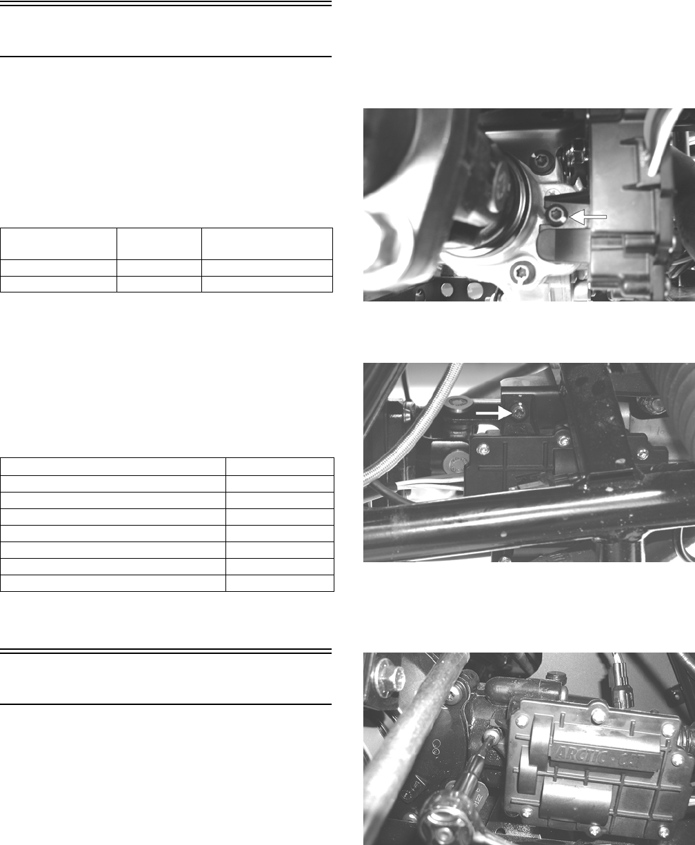
181
Drive System
GENERAL INFORMATION
All gear cases are tagged beneath a cover bolt. This tag is
marked with a production date code, sequence code, and
a ratio code. All gear cases are 4.0:1 ratio.
The die-cast aluminum housings have been assembled
with thread-rolling screws (trilobular). When assembling
with these screws, start the screws carefully into the
housing; then use the following torque values.
NOTE: Never reuse a lock nut. Once a lock nut has
been removed, it must be replaced with a new lock
nut.
SPECIAL TOOLS
A number of special tools must be available to the techni-
cian when performing service procedures in this section.
Refer to the current Special Tools Catalog for the appro-
priate tool description.
NOTE: Special tools are available from the Arctic
Cat Service Department.
Front Drive Actuator
NOTE: The actuator is not a serviceable compo-
nent. If it is defective, it must be replaced.
NOTE: The actuator will operate only when the igni-
tion switch is in the ON position.
The front drive actuator is located on the right side of the
front drive input housing. With the engine stopped and
the ignition switch in the ON position, a momentary
“whirring” sound can be heard each time the front drive
select switch is shifted. If no sound is heard, see the Elec-
trical System section. If the actuator runs constantly or
makes squealing or grinding sounds, the actuator must be
replaced.
REMOVING
1. Select LOCK on the drive select switch; then discon-
nect the connector on the actuator harness.
2. Using a T-30 torx wrench, remove the mounting cap
screw from the driveshaft side of the actuator.
PR189A
3. Remove the mounting cap screw from above the
actuator on the suspension side.
PR190A
4. Loosen but do not remove the mounting cap screw at
the front of the actuator; then slide the actuator to the
rear enough to clear the slotted mounting tab and the
selector shaft. Remove from the right side.
AG928
INSTALLING
1. Lubricate the O-rings on the actuator; then ensure all
mounting surfaces are clean and free of debris.
2. Align the actuator with the selector shaft and slide it
forward onto the shaft taking care to engage the cap
screw in the slot of the front mounting tab.
Size New Housing Reassembled
Housing
M6 (Torx T-30 Recess) 9 ft-lb 8 ft-lb
M8 (Torx T-40 Recess) 28 ft-lb 23 ft-lb
Description p/n
Backlash Measuring Tool (24-Spline Axle) 0544-010
Backlash Measuring Tool (27-Spline Axle) 0544-011
CV Boot Clamp Tool 0444-120
Internal Hex Socket 0444-104
Pinion Gear/Shaft Removal Tool 0444-127
Gear Case Seal Installer Tool 0444-224
U-Joint Separator Tool 0444-128
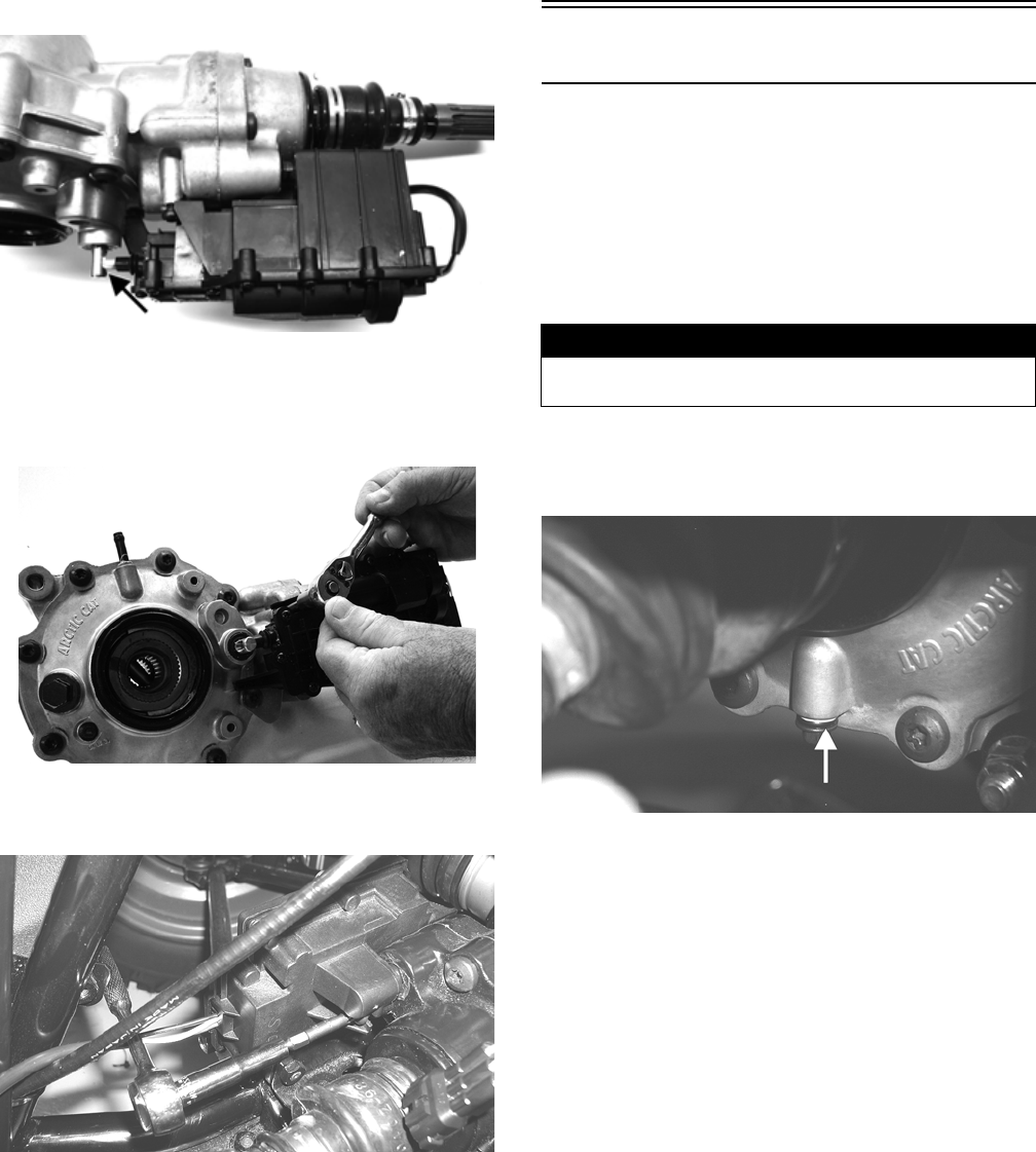
182
NOTE: Make sure to properly align the differential
lock actuator lever with the hole in the differential
lock plunger.
GC002A
3. While holding the actuator firmly forward, tighten
the front cap screw to hold the actuator in place; then
install but do not tighten the two remaining cap
screws.
GC001
4. Loosen the front cap screw; then tighten the cap
screw on the driveshaft side.
AG926
NOTE: It is important to tighten this cap screw while
the others are loose to ensure proper seating of the
actuator.
5. Tighten the remaining cap screws; then connect the
electrical plug to the main harness.
6. Turn the ignition switch to the ON position and
check the operation by shifting the drive select
switch several times.
7. Secure the wiring harness to the frame with a nylon
cable tie; then install the inner fender panel.
Front Differential
REMOVING
1. Remove the belly panel; then place the vehicle on
jack stands adjusted high enough to allow working
from the underside of the vehicle.
NOTE: The jack stands should be placed under the
main frame to avoid contact with front suspension
components.
2. Remove the drain plug and drain the gear lubricant
into a drain pan; then install the plug and tighten to
45 in.-lb.
PR022A
3. Remove the front wheels.
4. Set the parking brake; then turn the ignition switch to
the ON position and select LOCK on the drive select
switch.
5. Remove the cotter pin securing the axle nut; then
remove the nut.
6. Release the parking brake.
NOTE: It is not necessary to remove the brake
hoses from the calipers for this procedure.
7. Remove the two brake calipers. Account for the four
cap screws; then remove the hubs.
! WARNING
Make sure the vehicle is solidly supported on the jack
stands to avoid injury.
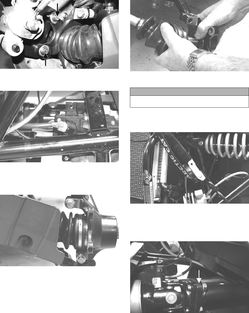
183
PR264A
8. Disconnect the front drive actuator connector from
the main harness.
PR191
9. Remove the lower and upper ball joint cap screws
taking care not to strip the threads on the ball joint
shaft; then using a rubber mallet, tap the end of the
axle and free it from the knuckle assembly.
PR193
10. Pull the steering knuckle away from the axle.
PR222
11. Support the axle to not allow it to drop or hang.
12. Remove the lower shock cap screws. Account for the
lock nuts; then move the shocks and upper A-arm up
and secure them with a strap.
PR200
13. On the XTZ, scribe match marks on the front input
drive flange and the front drive yoke flange; then
remove the cap screws securing the yoke and flange.
Separate the flanges but do not remove the drive-
shaft.
PR198A
14. Push the axle shaft toward the differential to release
the “plunge” coupler; then remove the axle from the
differential. Repeat for the opposite side.
NOTE: Keeping the axle level will aid in removal.
CAUTION
The axle must be supported. If the axle is allowed to
drop or hang, damage to the inner CV joint may occur.
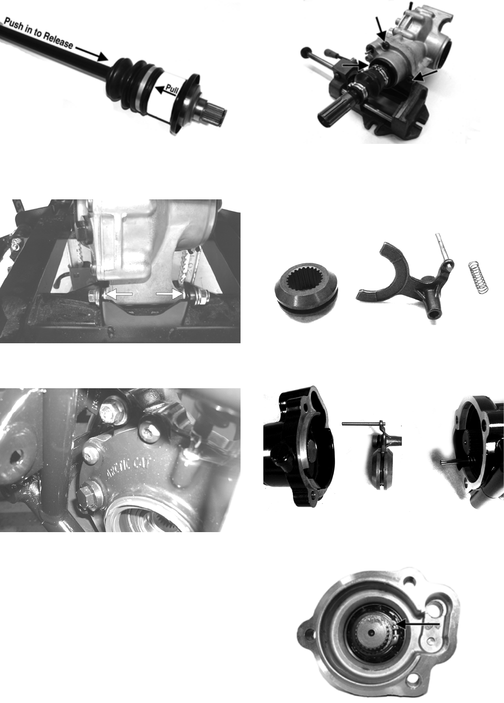
184
PR729C
15. Remove the lower differential mounting cap screw.
Account for a lock nut and four washers. Note the
position of the washers for assembling.
PR205A
16. Remove the upper differential mounting cap screw.
Account for a lock nut and two washers.
CD016
17. Free the differential assembly from the frame mount-
ings; then lower the differential through the frame.
Disassembling Input Shaft
1. Using a T-40 torx wrench, remove the cap screws
securing the pinion housing.
GC004A
2. Using a rubber mallet, remove the housing. Account
for a gasket. Remove the fork, collar, and spring.
Note the location of all the components for assem-
bling purposes.
GC015
CD106
3. Remove the snap rings from the input shaft; then
remove the input shaft from the pinion housing.
GC009A
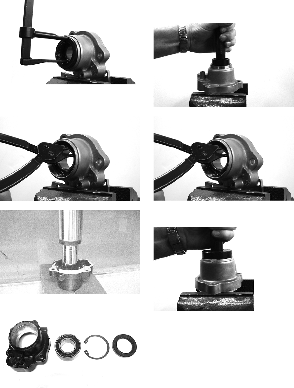
185
4. Using a seal removal tool, remove the input shaft
seal. Account for a spacer.
GC010
5. Remove the snap ring securing the input shaft bear-
ing; then place the pinion housing in a press and
remove the bearing.
GC011
AF984
KX219
Assembling Input Shaft
1. Place the pinion housing in a press and install the
input shaft bearing. Secure the bearing with the
existing snap ring making sure the sharp edge of the
snap ring faces to the outside.
GC012
GC011
2. Install the input shaft seal making sure it is fully
seated in the edge of the housing.
GC014
3. Lubricate the input shaft with High-Performance #2
Molybdenum Disulphide Grease packing the boot
ribs and splines; then assemble allowing excess
grease to freely escape. Slight pressure on the boot
will be present during assembly. Secure with new
clamps.
NOTE: Any time drive splines are separated, clean
all splines with parts-cleaning solvent and dry with
compressed air; then lubricate with recommended
grease.
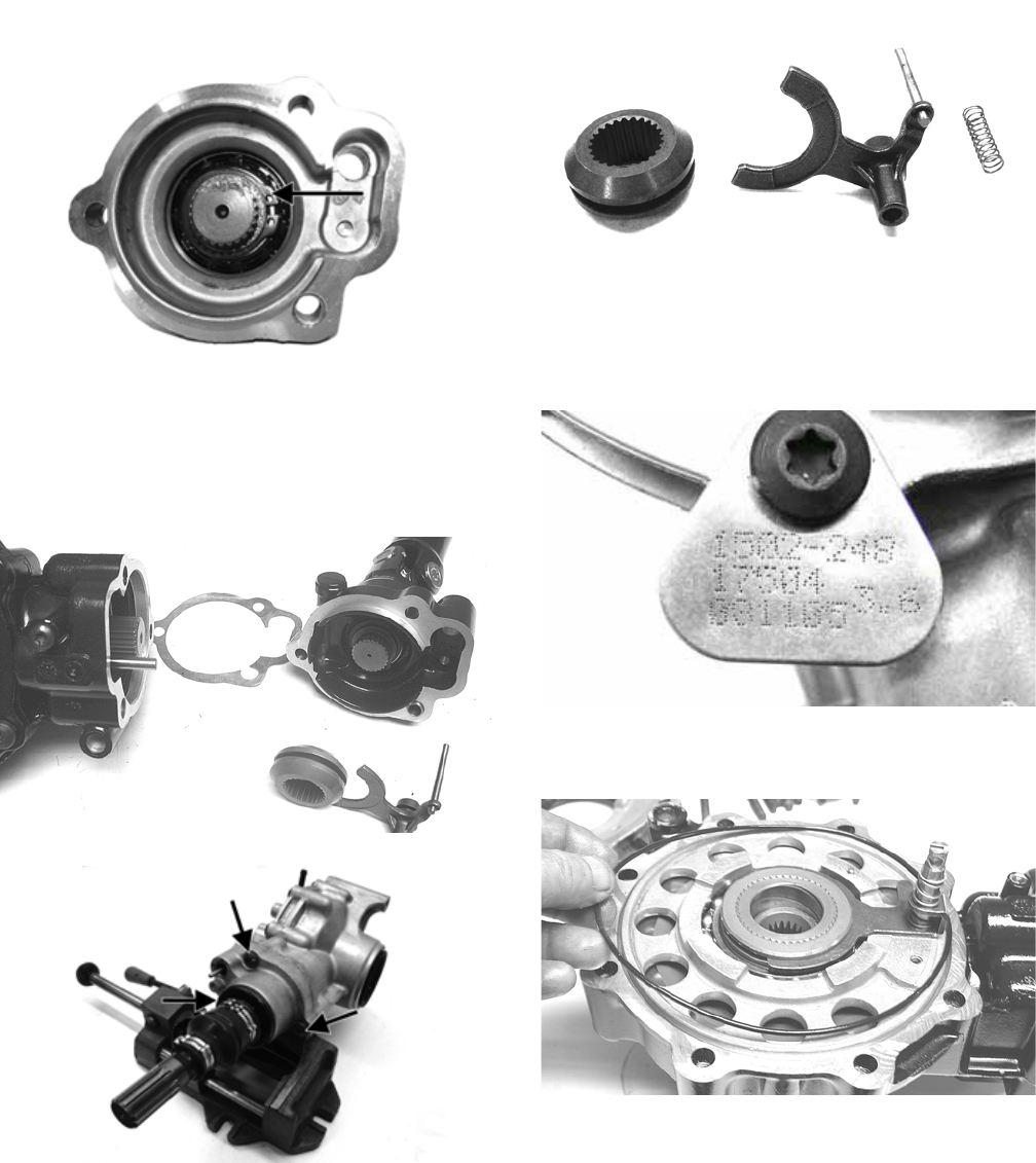
186
4. Install the input shaft into the pinion housing; then
secure in the bearing with a circlip.
GC009A
5. Place the pinion housing with new gasket onto the
differential housing; then secure with existing cap
screws. Tighten to 23 ft-lb.
NOTE: If a new differential housing is being
installed, tighten the cap screws to 28 ft-lb.
KX209
GZ004A
Disassembling Differential
Assembly
NOTE: This procedure can be performed on a rear
gear case.
1. Using a T-40 torx wrench, remove the cap screws
securing the pinion housing. Account for the coupler,
fork, and spring (differential only).
GC015
2. Using a T-40 torx wrench, remove the cap screws
securing the differential cover. Account for and make
note of the ID tag location for assembling purposes.
GC003
3. Using a plastic mallet, tap lightly to remove the dif-
ferential cover. Account for an O-ring.
KX174
NOTE: If the cover is difficult to remove, pry on the
cover in more than one recessed location.
4. Remove the splined coupler, shifter fork, pin, and
spring of the differential lock assembly and set aside.
Note position of parts for assembling purposes.
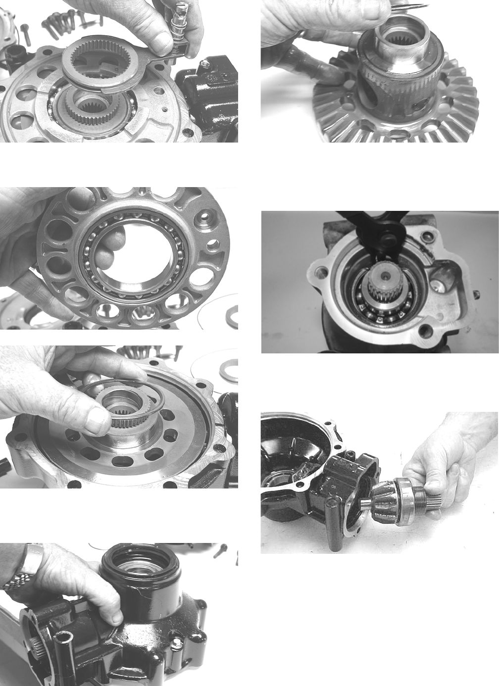
187
KX175
5. Remove the left differential bearing flange assembly
and account for a shim. Mark the shim as left-side.
KX177
KX178
6. Place the differential with the open side down; then
lift the housing off the spider assembly. Account for
shim(s) and mark as right-side.
KX179
KX181
Disassembling Pinion Gear
1. Remove the internal snap ring securing the pinion
bearing in the housing.
WC430
2. Using the Pinion Gear/Shaft Removal Tool and a
hammer, remove the pinion gear from the gear case
housing.
CC878
3. Secure the pinion gear in a bearing puller; then
remove the pinion bearing using a press. Account for
a collar and a bearing.
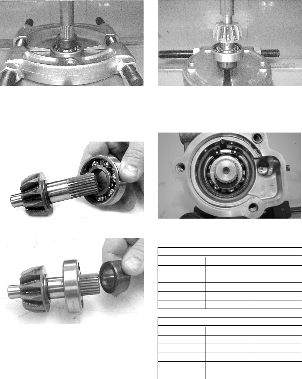
188
CC879
4. Remove any reusable parts from the gear case hous-
ing; then discard the housing and lock collar.
Assembling Pinion Gear
1. Install the bearing onto the pinion shaft. Install the
pinion shaft collar.
CC882
CC883
2. Place the pinion assembly in a bearing puller; then
install the bearing using a press.
CC884
3. Coat a new needle bearing and the bearing pocket of
a new gear case/differential housing with red Loctite
#271; then using a suitable driver, install the bearing
lightly seated against the bearing seats. Do not push
the bearing too far into the pocket.
WC429
Shimming Procedure/Shim
Selection
It is very important to adjust bevel gears for the proper
running tolerances. Gear life and gear noise are greatly
affected by these tolerances; therefore, it is very impor-
tant to properly adjust any gear set prior to final assem-
bly.
The following procedure can be used on both front differ-
ential or rear drive gear case.
Case-Side Shims (Backlash)
p/n mm in.
0402-405 1.3 0.051
0402-406 1.4 0.055
0402-407 1.5 0.059
0402-408 1.6 0.063
0402-409 1.7 0.067
Cover-Side Shims (Ring Gear End-Play)
p/n mm in.
1402-074 1.3 0.051
1402-075 1.4 0.055
1402-076 1.5 0.059
1402-077 1.6 0.063
1402-078 1.7 0.067

189
NOTE: All bearings must be installed in the gear
case and the pinion properly installed before pro-
ceeding.
Backlash
NOTE: Always set backlash prior to any other shim-
ming.
1. Install the existing shim or a 0.051-0.055-in. shim on
the gear case side of the ring gear assembly.
GC031A
2. Install the ring gear with shim in the gear case; then
while holding the pinion stationary, rock the ring
gear forward and back to determine if any backlash
exists. If no backlash exists, install a thicker shim
and recheck.
GC036A
3. Install the bearing flange onto the gear case cover
making sure the alignment/locating pin engages the
locating hole in the cover; then make sure the bear-
ing flange is completely seated in the cover.
GC032A
GC033A
4. Install the existing shim or a 0.063 in. shim on the
cover side of the ring gear; then place the assembled
gear case cover onto the gear case and secure with
three cap screws. Tighten evenly using a crisscross
pattern.
GC036B
5. Place the appropriate Backlash Measuring Tool into
the splines of the ring gear and install a dial indicator
making sure it contacts the gauge at a 90° angle and
on the index mark.
GC040
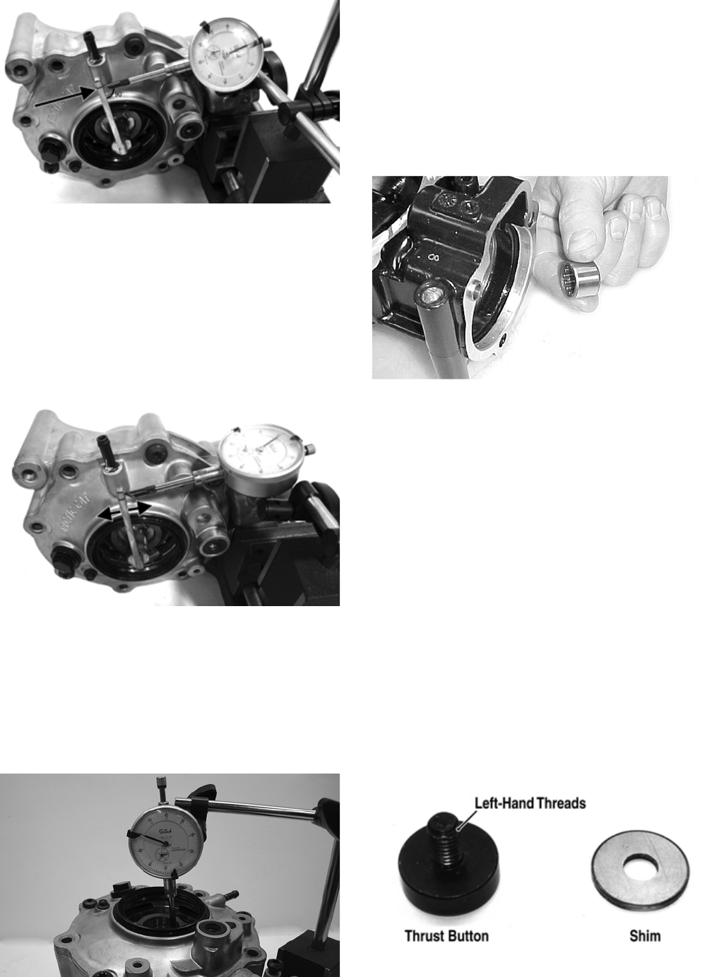
190
GC039A
6. Zero the dial indicator; then while holding the pinion
stationary, rock the ring gear assembly forward and
back and record the backlash. Backlash must be
0.011-0.015 in. If backlash is within specifications,
proceed to Ring Gear End-Play. If backlash is not
within specifications, increase shim thickness to
increase backlash or decrease shim thickness to
decrease backlash.
NOTE: Higher backlash settings usually result in
quieter gear operation.
GC037A
Ring Gear End-Play
After correcting backlash, ring gear end-play can be
adjusted. To adjust end-play, use the following proce-
dure.
1. Secure the gear case in a holding fixture with the
cover side up; then install a dial indicator contacting
the ring gear axle flange.
GC035
2. Zero the dial indicator; then push the ring gear
toward the dial indicator and release. End-play
should be 0.004-0.008 in.
3. To increase end-play, decrease the shim thickness. To
decrease end-play, increase the shim thickness.
NOTE: Once proper backlash and end play are
established, the gear case can be assembled (see
Assembling Differential Assembly in this sub-sec-
tion).
CC888
RING GEAR/THRUST BUTTON
Removing
Remove the thrust button from the gear case cover
(left-hand threads). Account for a shim.
Inspecting
1. Inspect the ring gear for excessive wear or discolor-
ation.
2. Inspect the thrust button for excessive wear or dis-
coloration.
3. Inspect the bearings for discoloration, roughness, or
excessive wear.
Installing/Shimming
NOTE: Ring gear end-play must be adjusted prior to
selecting shim for the thrust button.
1. Install the thrust button with shim into the gear case
cover and tighten securely (left-hand threads).
GC057A
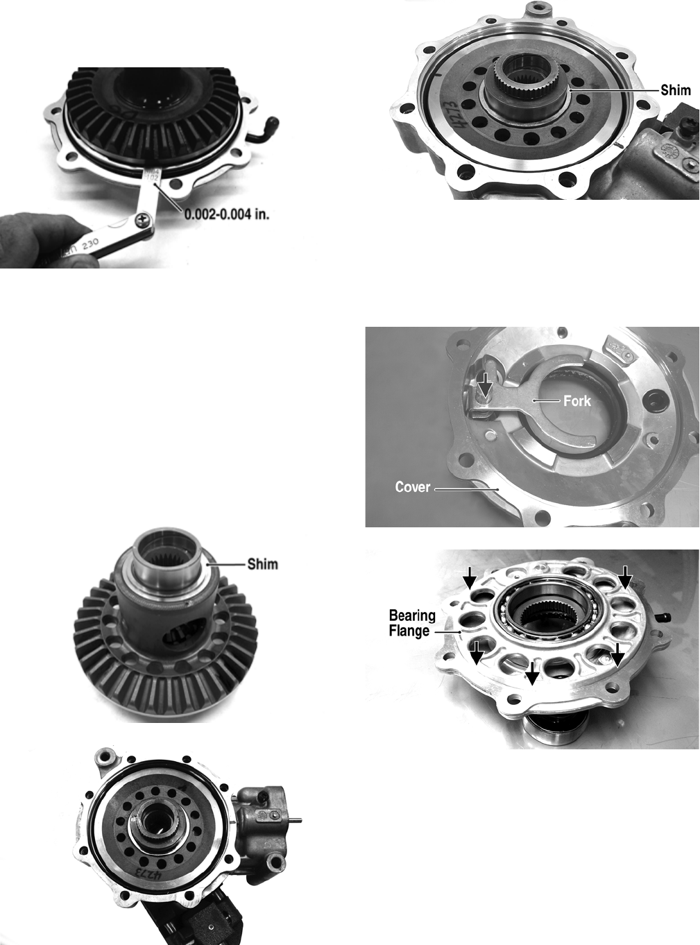
191
2. Place the ring gear with selected shim into the cover
and measure the ring gear to thrust button clearance
with a thickness gauge. Clearance should be
0.002-0.004 in.
GC058A
3. If clearance is as specified, remove the ring gear and
thrust button; then place a drop of red Loctite #271
on the threads and tighten to 8 ft-lb (left-hand
threads).
4. If clearance is not as specified, repeat steps 1 and 2
using thicker (clearance too great) or thinner (clear-
ance too small) until correct specification is reached.
Assembling Differential Assembly
1. With the pinion gear and new bearings installed,
place the selected (backlash) shim on the gear case
side of the ring gear with the chamfered side toward
the ring gear; then install into gear case/differential
housing.
GC031A
GC020
2. Place the selected (end-play) shim, chamfered side
toward the gear, onto the cover side of the ring gear.
GC036B
NOTE: The spider and ring gear assembly must be
replaced as a complete unit.
3. Assemble the fork and sliding collar into the cover
assembly; then install the left bearing flange/bearing
assembly and seat firmly into the cover.
CF266A
CF267A
4. Apply a liberal coat of grease to the O-ring; then
install it on the assembled cover assembly making
sure to seat the O-ring completely down around the
circumference of the bearing flange.
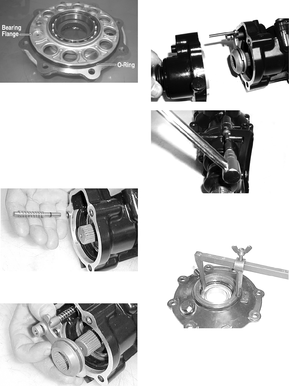
192
CF275A
5. Making sure the O-ring is properly positioned on the
differential housing cover assembly, install the cover
with existing cap screws (coated with green Loctite
#270). Account for the ID tag. Tighten the cap
screws evenly to 23 ft-lb.
NOTE: Grease can be applied to the O-ring for ease
of assembling.
NOTE: If a new housing is being installed, tighten
the cap screws to 28 ft-lb.
6. Install the shift fork shaft w/spring into the housing
making sure the shaft O-ring is positioned to the
inside.
CC892
7. Install the shift fork assembly making sure the fork
leg is facing upward. Apply a small amount of oil to
the gasket; then install the gasket.
CC893
8. Place the input shaft assembly onto the gear case
housing; then secure with the existing cap screws.
Tighten to 23 ft-lb.
NOTE: If a new housing is being installed, tighten
the cap screws to 28 ft-lb.
CD103
CD110
Removing/Installing Axle Seal
NOTE: This procedure can be performed on a rear
gear case.
1. Remove the seal using a seal removal tool.
CC899
NOTE: Prior to installing the seal, apply High-Per-
formance #2 Molybdenum Disulphide grease to the
seal outside diameter.
2. Using Gear Case Seal Installer Tool, evenly press the
seal into the cover bore until properly seated.
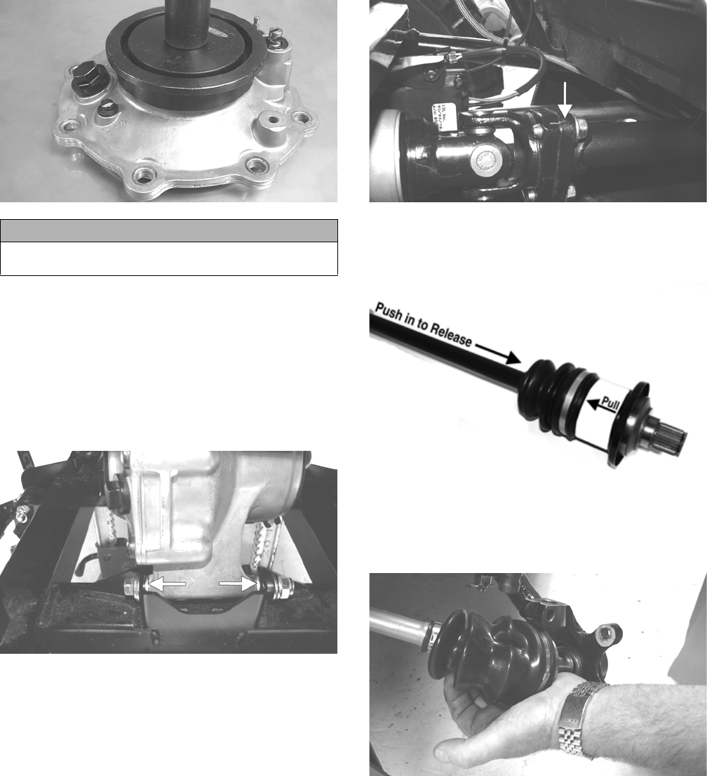
193
CF278
3. Repeat steps 1-2 for the opposite side.
INSTALLING DIFFERENTIAL
1. Place the differential assembly into position in the
frame; then install the top mounting cap screw, two
washers, and lock nut. Do not tighten at this time.
2. Install the lower differential mounting cap screw,
washers, and lock nut. Note the correct location for
the washers.
PR205A
3. Tighten the nuts to 38 ft-lb.
4. Pour 275 ml (9.3 fl oz) of SAE 80W-90 hypoid lubri-
cant into the differential and install the fill plug.
Tighten to 16 ft-lb.
5. Align the scribed match marks on the front input
drive flange and the front drive yoke flange; then
secure with the cap screws tightened to 20 ft-lb.
PR198A
6. Push the axle shaft into the CV coupler to release the
locking ring while pulling back on the CV coupler and
slide the drive axle into place.
PR729C
7. Install the knuckle assemblies onto the axles and ball
joints; then secure with four cap screws taking care
not to damage the threads when installing. Tighten to
35 ft-lb.
PR201
CAUTION
Make sure the tool is free of nicks or sharp edges or
damage to the seal may occur.
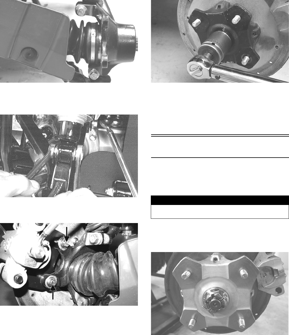
194
PR193
8. Secure the lower shock eyelets with cap screws and
lock nuts. Tighten to 20 ft-lb (XT/XTX) or 35 ft-lb
(XTZ).
AF897D
9. Install the brake calipers. Secure with new
“patch-lock” cap screws tightened to 20 ft-lb.
PR264A
10. Connect the front drive actuator connector to the
main harness; then secure the wires to the frame with
nylon ties.
11. Apply a light coat of multi-purpose grease to the hub
splines; then install the hubs and nuts. Tighten to 200
ft-lb; then install new cotter pins.
PR256
12. Install the wheels and tighten in a crisscross pattern
in 20 ft-lb increments to 80 ft-lb (aluminum wheels)
or 45 ft-lb (steel wheels).
13. Remove the vehicle from the support stand.
14. Install the belly panel.
Drive Axles
REMOVING REAR DRIVE AXLE
1. Secure the vehicle on a support stand to elevate the
wheels.
2. Set the parking brake; then remove the wheels.
3. Remove the cotter pins securing the axle nuts; then
remove the nuts.
KX041
4. Slide the hub out of the knuckle and set aside.
! WARNING
Make sure the vehicle is solidly supported on the sup-
port stand to avoid injury.
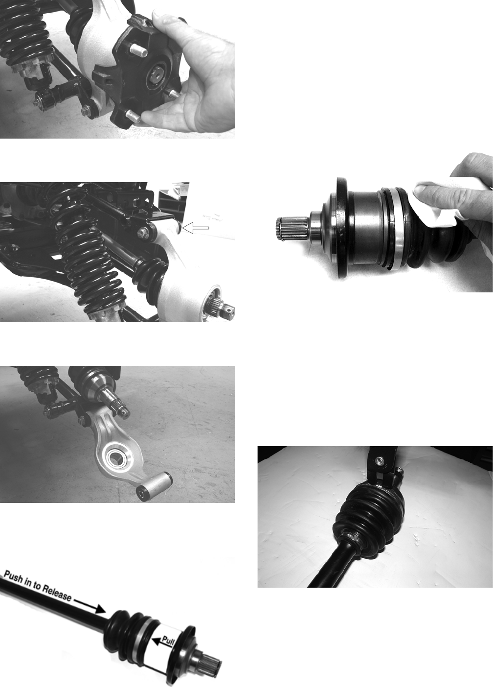
195
PR221
5. Remove the cap screw and lock nut securing the knuckle
to the upper A-arm. Discard the lock nut.
PR220A
6. While holding the drive axle stationary, pull the top of
the knuckle out and down until it is free of the drive axle.
PR218
7. Place a drain pan under the vehicle to contain any oil
leakage; then pushing the axle shaft in, pull the axle
assembly from the gear case.
PR729C
REMOVING FRONT DRIVE AXLE
NOTE: For removing a front drive axle, see Front
Differential in this section.
CLEANING AND INSPECTING
AXLES
NOTE: Always clean and inspect the drive axle com-
ponents to determine if any service or replacement is
necessary.
1. Using a clean towel, wipe away any oil or grease
from the axle components.
CD019
2. Inspect boots for any tears, cracks, or deterioration.
NOTE: If a boot is damaged in any way, it must be
replaced with a boot kit.
DISASSEMBLING AXLES
NOTE: Only the boots are serviceable on the axles;
if any other component is worn or damaged, the axle
must be replaced.
1. Using CV Boot Clamp Tool, remove and retain both
clamps for assembly purposes.
CF337
2. Place the white-striped end of the CV joint into a
vise.
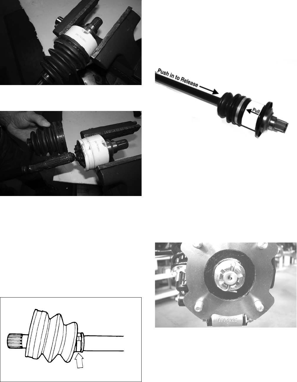
196
CF335
3. To disengage the axle from the CV joint, sharply pull
back on the axle; then slide the boot off of the axle.
CF334
NOTE: Steps 1-3 can be used to replace the out-
board boot.
ASSEMBLING AXLES
1. Install the inner boot with the small clamp making
sure the ends of the clamp are positioned correctly.
NOTE: The boot is positioned correctly when the
small end of the boot seats down into the recessed
groove.
2. Using the boot clamp tool, secure the small clamp of
the inner boot.
ATV-1048
3. Apply 80 grams (2/3 of contents) of grease from the
pack into the bearing housing.
NOTE: Steps 1-3 can be used to replace the out-
board boot.
NOTE: In the outboard boot, use the final 40 grams
(1/3 of contents) of grease from the pack in the bear-
ing housing.
INSTALLING REAR DRIVE AXLE
1. Push the axle shaft into the CV coupler to release the
lock ring while pulling back on the CV coupler and
slide the drive axle into place in the gear case.
PR729C
NOTE: To ensure proper axle seating, give it a light
pull; the axle should remain “clipped” in place.
2. Swing the knuckle up and onto the drive axle; then
place the knuckle into place in the upper A-arm.
Secure the knuckle to the A-arm with a cap screw
and a new lock nut. Tighten to 35 ft-lb.
3. Place the hub into position on the axle followed by a
hex nut. Tighten the hex nut finger-tight at this time.
4. Tighten the hub hex nut (from step 3) to 200 ft-lb;
then install and spread a new cotter pin making sure
each side of the pin is flush to the hub nut.
CD027
5. Install the wheel. Tighten in a crisscross pattern in 20
ft-lb increments to 80 ft-lb (aluminum wheels) or to
45 ft-lb (steel wheels).
6. Remove the vehicle from the support stand and
release the parking brake.
INSTALLING FRONT DRIVE AXLE
1. Push the axle shaft into the CV coupler to release the
lock ring; then position the drive axle in the gear case
and steering knuckle; then insert the ball joints into
the steering knuckles. Secure with cap screws tight-
ened to 35 ft-lb.
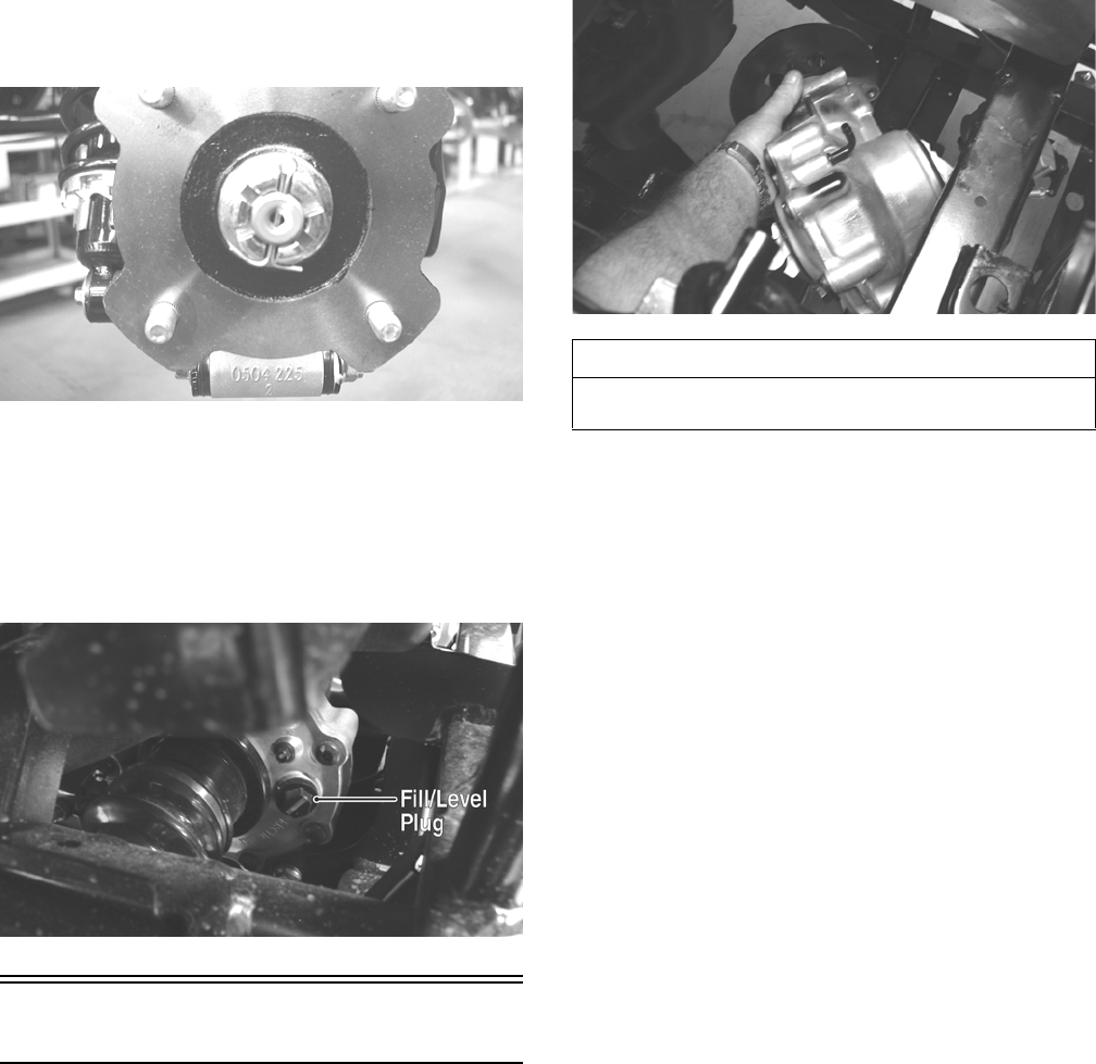
197
2. Secure the lower shock eyelet to the A-arm with a
cap screw and a new lock nut. Tighten to 35 ft-lb.
3. Slide the hub w/brake disc into position in the steer-
ing knuckle followed by an axle nut. Finger-tighten
at this time.
4. Install the brake caliper on the steering knuckle using
new “patch-lock” cap screws. Tighten to 20 ft-lb.
5. Set the parking brake; then turn the ignition switch to
the ON position, select LOCK on the drive select
switch. Turn the ignition switch to the OFF position.
6. Tighten the axle nut (from step 3) to 200 ft-lb; then
install and spread a new cotter pin making sure each
side of the pin is flush to the hub nut.
CD027
7. Install the wheel and tighten in a crisscross pattern in
20 ft-lb increments to 80 ft-lb (aluminum wheels) or
to 45 ft-lb (steel wheels).
8. Remove the vehicle from the support stand.
9. Check the front differential lubricant level and add
lubricant as necessary.
PR065A
Rear Gear Case
REMOVING
NOTE: Release the cargo box latch and allow the
cargo box to tilt back; then remove the cargo box lift
support by removing the cap screw and nut securing
the lower lift support to the frame. The cargo box will
tilt fully rearward.
1. Drain the lubricant from the rear gear case; then
remove both rear drive axles.
2. Remove the driveline brake caliper; then cut the
rear-most propeller shaft boot clamp and slide the
boot forward.
3. Remove the boot clamps on the rear driveline boot.
4. Remove the two cap screws and lock nuts securing
the rear gear case to the frame; then remove the gear
case through the upper left-side of the frame and lift
out the top.
PR207
RING GEAR/THRUST BUTTON
Removing
1. Remove the cap screws securing the gear case cover
to the gear case; then remove the ring gear.
2. Remove the thrust button from the gear case cover
(left-hand threads). Account for a shim.
Inspecting
1. Inspect the ring gear for excessive wear, missing or
chipped teeth, or discoloration.
2. Inspect the thrust button for excessive wear or dis-
coloration.
3. Inspect the bearings for discoloration, roughness, or
excessive wear.
NOTE: For servicing bearings or seals, see Front
Differential in this section.
Installing/Shimming
NOTE: Ring gear clearance must be adjusted prior
to selecting shim for the thrust button.
1. Install the thrust button with shim into the gear case
cover and tighten securely (left-hand threads).
AT THIS POINT
For servicing the input shaft, pinion gear, needle bear-
ing, and axle seal, see Front Differential in this section.
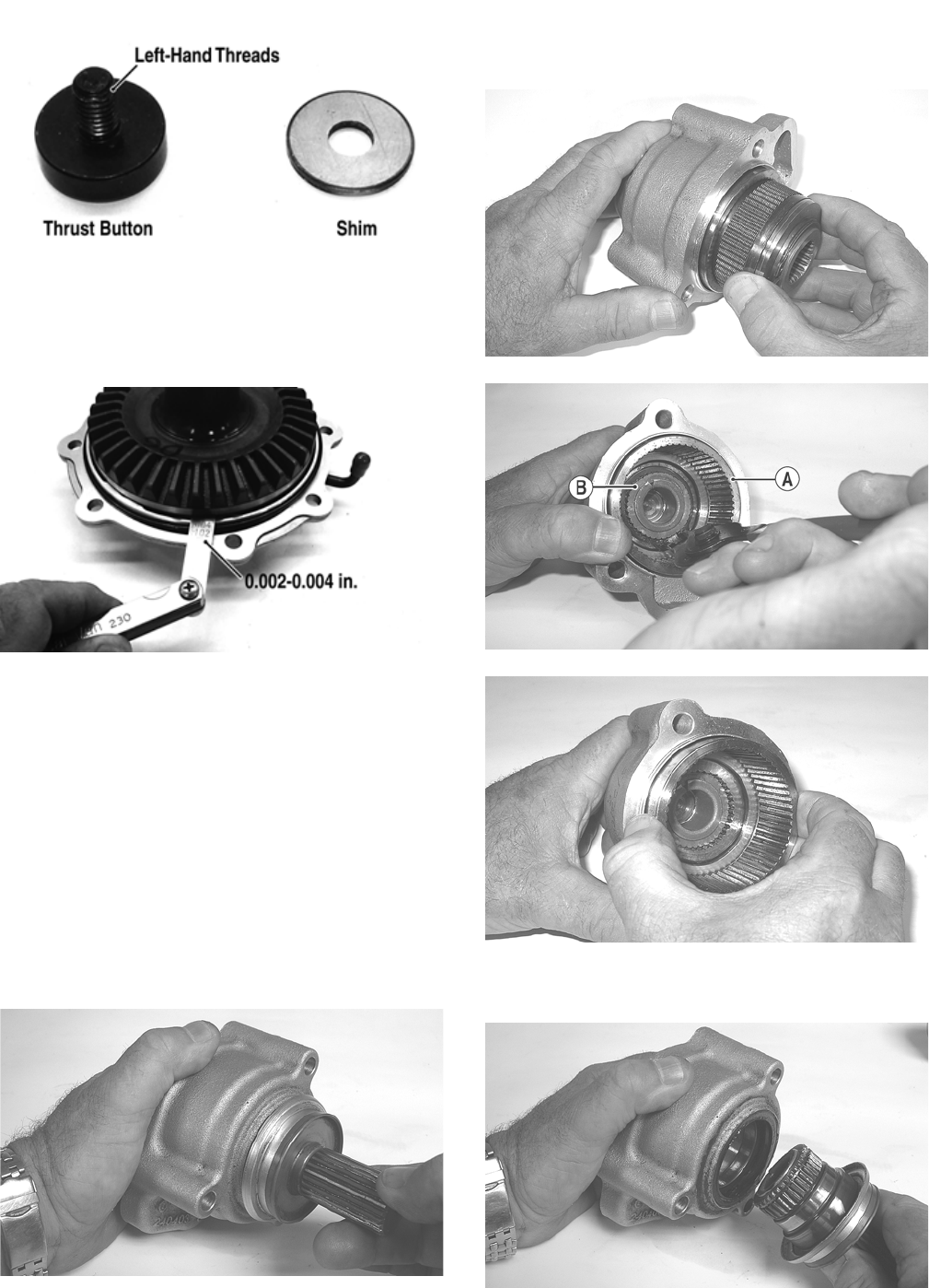
198
GC057A
2. Place the ring gear with selected shim into the cover
and measure the ring gear to thrust button clearance
with a thickness gauge. Clearance should be
0.002-0.004 in.
GC058A
3. If clearance is as specified, remove the ring gear and
thrust button; then place a drop of red Loctite #271
on the threads and tighten to 8 ft-lb (left-hand
threads).
4. If clearance is not as specified, repeat steps 1 and 2
using thicker (clearance too great) or thinner (clear-
ance too small) until correct specification is reached.
REAR DRIVE INPUT SHAFT/
HOUSING
Removing/Disassembling
1. Remove the cap screws securing the rear drive input
shaft/housing to the rear gear case; then remove the
input housing assembly.
GZ183
2. On the XTZ model, remove the clutch pack from the
clutch basket; then remove the snap ring securing the
clutch basket (A) to the input shaft (B) and remove
the clutch basket.
GZ392
GZ176A
GZ177
3. Remove the input shaft from the input housing; then
remove the oil seal.
GZ180
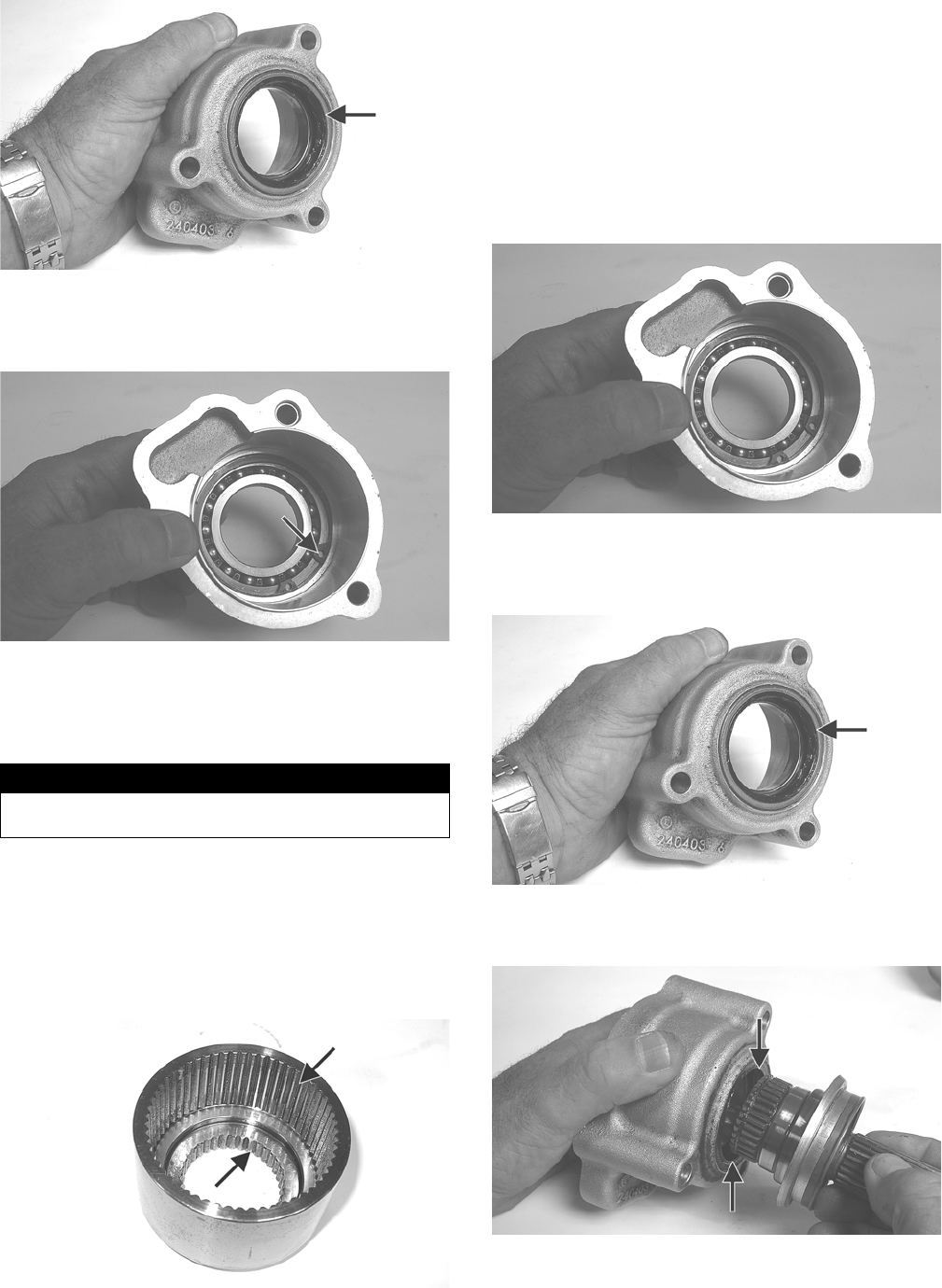
199
GZ182A
4. Remove the snap ring retaining the input bearing and
using an appropriate bearing driver, press the bearing
from the housing.
GZ184A
Cleaning and Inspecting
1. Wash all parts in parts cleaning solvent and dry with
compressed air.
2. Clean all gasket material and sealant from mating
surfaces.
3. Inspect bearings, shafts, and housing for excessive
wear, cracks, or discoloration.
4. Inspect the clutch basket (XTZ) for wear in splines
or cracks in the housing.
GZ178A
5. Inspect the clutch pack (XTZ) for signs of discolor-
ation.
NOTE: The clutch pack is not a serviceable compo-
nent. If worn, discolored, or damaged in any way, it
must be replaced.
Assembling/Installing
1. Install a new bearing into the input housing and
secure with the snap ring (flat side directed away
from bearing).
GZ184
2. Using a suitable seal driver, install a new oil seal into
the front of the input housing until the seal is flush
with the housing.
GZ182A
3. Apply grease to the lips of the oil seal; then install
the input shaft into the input bearing and housing.
GZ179A
4. Install the clutch basket (XTZ) onto the input shaft
and secure with the snap ring (flat side directed out-
ward); then install the clutch pack into the basket.
! WARNING
Always wear safety glasses when working with com-
pressed air.
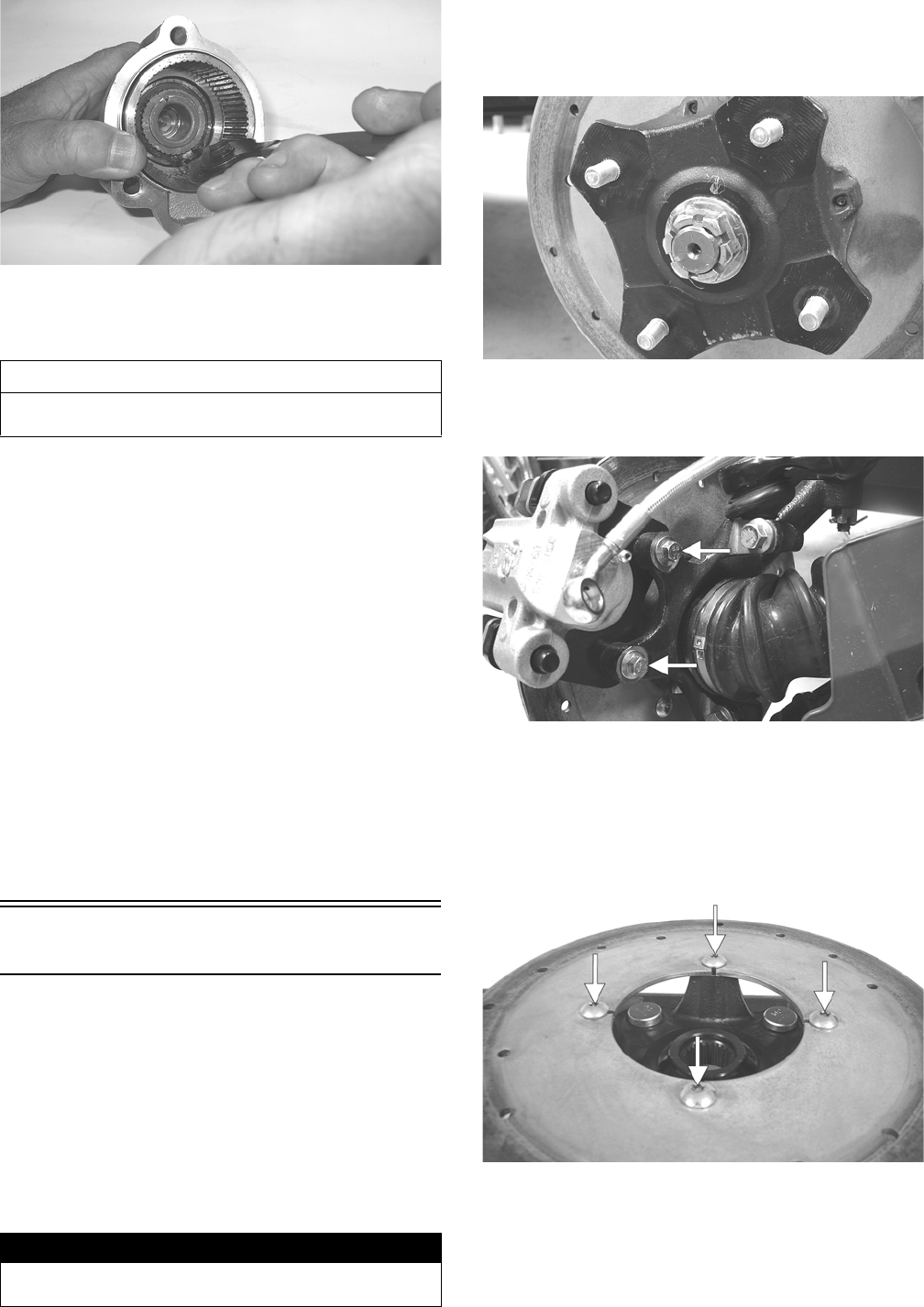
200
GZ176
5. Using a new gasket, install the assembled rear drive
input shaft/housing onto the rear drive gear case and
secure with the three cap screws. Tighten to 23 ft-lb.
INSTALLING
1. Slide the gear case into position down through the
upper-left side of the frame; then align the driveline
splines to the differential input coupler and engage
the driveshaft and differential.
2. Pack the driveline boot with the appropriate grease;
then secure with the boot clamps using CV Boot
Clamp Tool.
3. Secure the differential to the frame with two
through-bolts and secure with lock nuts and flat
washers. Tighten to 38 ft-lb.
4. Install the rear drive axles (see Drive Axles in this
section).
5. Install the brake caliper and tighten the new
“patch-lock” cap screws to 20 ft-lb; then adjust the
parking brake (see Parking Brake in the Periodic
Maintenance section).
6. Fill the gear case with the appropriate lubricant.
Hub
REMOVING
1. Secure the vehicle on a support stand to elevate the
wheel; then remove the wheel.
NOTE: Removing or tightening of the hub nuts
requires the axles be locked. To lock the rear axle, set
the parking brake. To lock the front axle, turn the igni-
tion switch to ON, select LOCK on the drive select
switch; then set the parking brake and turn the igni-
tion switch to OFF.
2. Remove the cotter pin from the axle.
NOTE: During assembly, new cotter pins should be
installed.
PR257
3. Remove the hub nut securing the hub.
4. Remove the brake caliper (front only).
PR243A
5. Remove the hub assembly.
6. Remove the four cap screws securing the brake disc
(front hub only).
NOTE: Applying heat to the head of each cap screw
will aid in removal.
PR254A
NOTE: Heating the head of each cap screw with a
torch will aid in the removal.
CLEANING AND INSPECTING
1. Clean all hub components.
AT THIS POINT
For servicing the input shaft, pinion gear, needle bear-
ing, and axle seal, see Front Differential in this section.
! WARNING
Make sure the vehicle is solidly supported on the sup-
port stand to avoid injury.
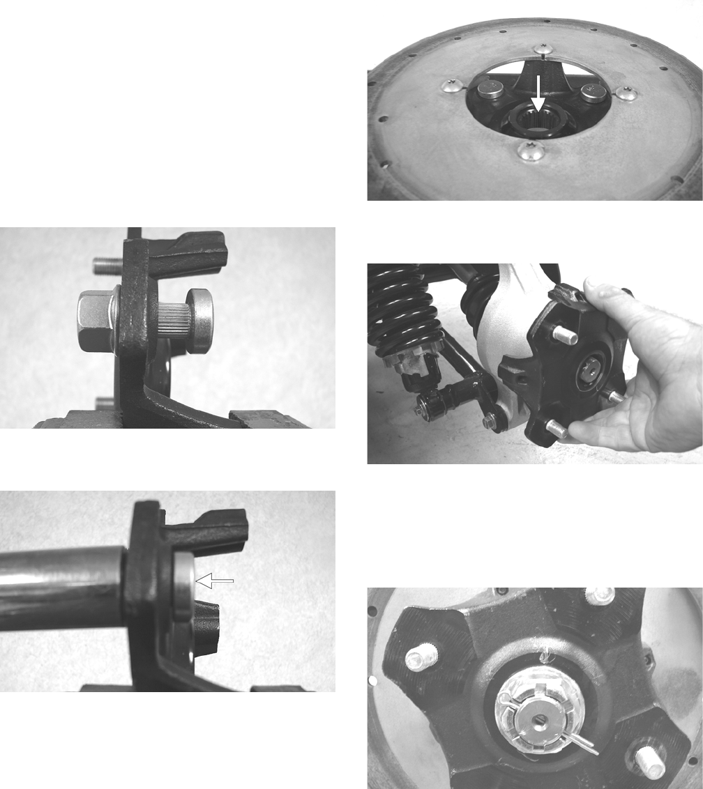
201
2. Inspect all threads for stripping or damage.
3. Inspect the brake disc (if applicable) for cracks or
warping.
4. Inspect the hub for pits, cracks, loose studs, or spline
wear.
REPLACING WHEEL STUDS
1. Secure the hub in a suitable holding fixture and
remove the brake disc (if applicable).
2. Drive the damaged stud out of the hub; then place the
new stud into the hub and thread on an appropriate
flange nut.
PR250
3. Using a socket and ratchet handle, tighten the nut
until the stud is fully drawn into the hub.
PR252A
INSTALLING
1. Secure the brake disc (if applicable) to the hub with
the four cap screws coated with red Loctite #271.
Tighten to 15 ft-lb.
2. Apply grease to the splines in the hub.
PR254B
3. Install the hub assembly onto the axle; then set the
parking brake.
PR221
4. Secure the hub assembly with the nut. Tighten to 200
ft-lb; then secure with a new cotter pin.
NOTE: If the cotter pin can not be inserted due to
misalignment of the hole in the axle and the slots in
the nut, tighten the nut until properly aligned.
PR258
5. For front hubs, secure the brake calipers to the
knuckle with two new “patch-lock” cap screws tight-
ened to 20 ft-lb.
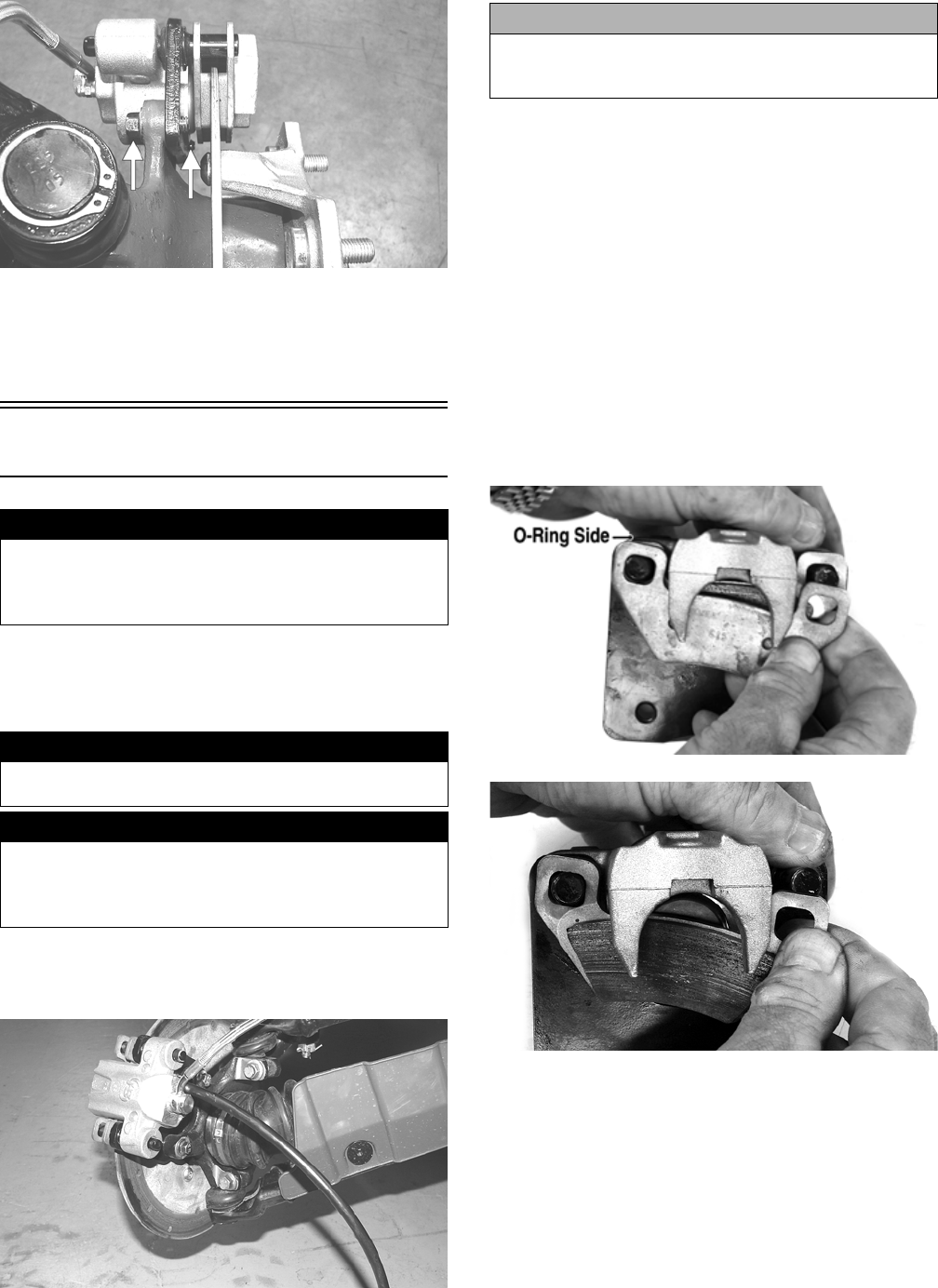
202
PR377B
6. Install the wheel and tighten in a crisscross pattern in
20 ft-lb increments to 80 ft-lb (aluminum wheels) or
45 ft-lb (steel wheels).
7. Remove the vehicle from the support stand.
Hydraulic Brake Caliper
REMOVING/DISASSEMBLING
1. Secure the vehicle on a support stand to elevate the
wheel; then remove the wheel.
2. Drain the brake fluid from the caliper, hose, and mas-
ter cylinder through the bleed screw by pumping the
brake pedal.
PR235
NOTE: Whenever brake components are removed,
disassembled, or repaired where brake fluid is
exposed to air, drain all fluid and replace with new
DOT 4 brake fluid from an unopened container. Brake
fluid readily absorbs moisture from the air signifi-
cantly lowering the boiling point. This increases the
chance of vapor lock reducing braking power and
increasing stopping distance.
3. Remove the brake hose from the caliper and close
the bleed screw; then remove the caliper.
4. Compress the caliper holder against the caliper
(opposite the O-ring side) and remove the outer
brake pad; then remove the inner brake pad.
NOTE: If brake pads are to be returned to service,
do not allow brake fluid to contaminate them.
PR237A
PR238
5. Remove the caliper holder from the caliper and dis-
card the O-ring.
! WARNING
Arctic Cat recommends only authorized Arctic Cat ROV
dealers perform hydraulic brake service. Failure to
properly repair brake systems can result in loss of con-
trol causing severe injury or death.
! WARNING
Make sure the vehicle is solidly supported on the sup-
port stand to avoid injury.
! WARNING
Never let brake fluid contact the eyes. Damage to the
eyes will occur. Always wear appropriate protective
safety goggles and latex gloves when handling brake
fluid.
CAUTION
Brake fluid is highly corrosive. Do not spill brake fluid
on any surface of the vehicle and do not reuse brake
fluid.
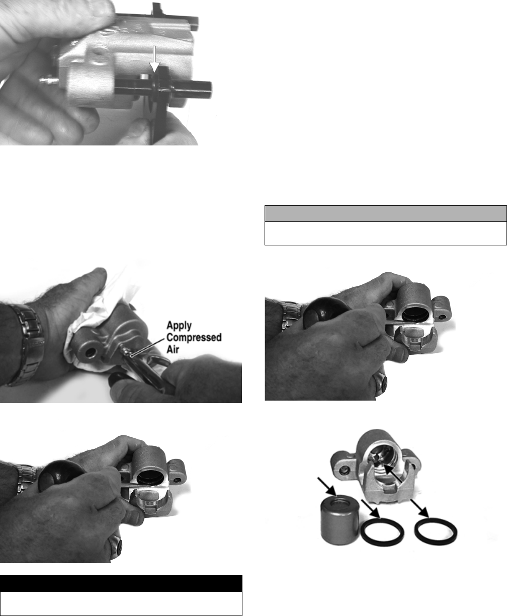
203
PR239B
NOTE: The O-ring is used for shipping purposes
and provides no function in operation.
6. Cover the piston end of the housing with a shop
towel; then keeping fingers clear of piston travel,
apply compressed air to the fluid port to blow the
piston free of the housing. Account for two seal rings
in the housing.
PR713A
PR715
7. Using an appropriate seal removal tool, carefully
remove the seals from the brake caliper housing; then
remove four O-rings from the brake caliper housing
noting the location of the different sized O-rings. Dis-
card all seals, O-rings, and crush washers.
CLEANING AND INSPECTING
1. Clean all caliper components (except the brake pads)
with DOT 4 brake fluid. Do not wipe dry.
2. Inspect the brake pads for damage and excessive
wear.
NOTE: For measuring brake pads, see the Periodic
Maintenance section.
3. Inspect the brake caliper housings for scoring in the
piston bores, chipped seal ring grooves, or signs of
corrosion or discoloration.
4. Inspect the piston surface for scoring, discoloration,
or evidence of binding or galling.
5. Inspect the caliper holder for wear or bending.
ASSEMBLING/INSTALLING
1. Install new seals into the brake caliper housing and
apply a liberal amount of DOT 4 brake fluid to the
cylinder bore of the housing, seals, and brake piston.
PR715
PR717A
2. Press the piston into the caliper housing using hand
pressure only. Completely seat the piston; then wipe
off any excessive brake fluid.
! WARNING
Make sure to hold the towel firmly in place or the piston
could be ejected from the housing causing injury.
CAUTION
Make sure the seals are properly in place and did not
twist or roll during installation.
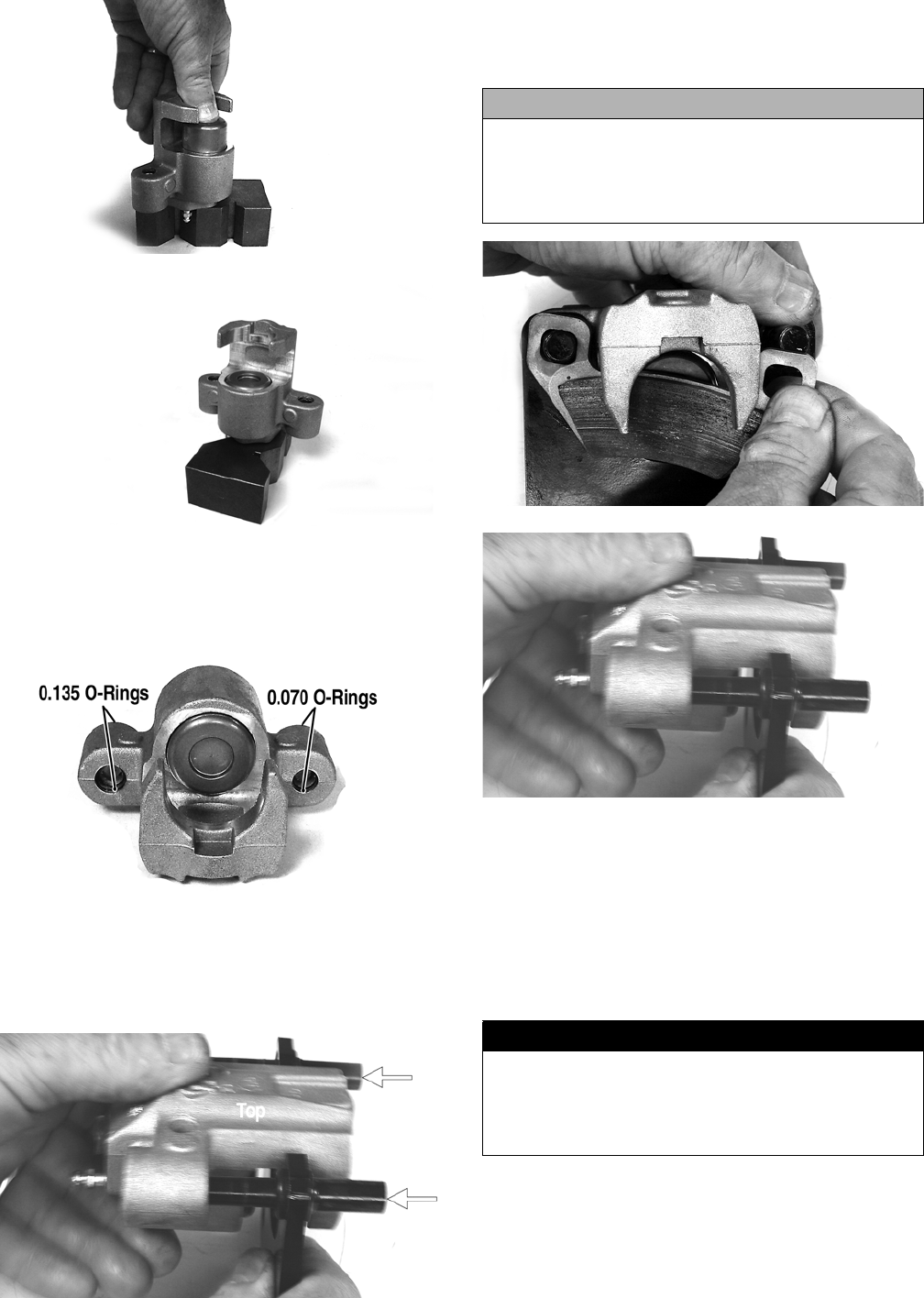
204
PR711A
PR712
3. Apply high-temperature silicone grease (supplied
with the O-ring kit) to the inside of the caliper holder
bores and O-rings; then install the four O-rings into
the caliper.
PR719C
4. Install the caliper onto the caliper holder making sure
the caliper and holder are correctly oriented.
NOTE: It is very important to apply silicone grease
to the O-rings and caliper bores prior to assembly.
PR239C
5. Making sure brake fluid does not contact the brake
pads, compress the caliper holder toward the caliper
and install the inner brake pad; then install the outer
pad.
PR238
PR239
6. Place the brake caliper assembly into position and
secure with new “patch-lock” cap screws. Tighten
the caliper to 20 ft-lb.
7. Place a new crush washer on each side of the brake
hose fitting and install it on the caliper. Tighten to 20
ft-lb.
8. Fill the reservoir; then bleed the brake system (see
Periodic Maintenance - Hydraulic Brake System).
9. Install the wheel. Tighten in a crisscross pattern in 20
ft-lb increments to 80 ft-lb (aluminum wheels) or to
45 ft-lb (steel wheels).
10. Remove the vehicle from the support stand and ver-
ify brake operation.
CAUTION
If brake pads become contaminated with brake fluid,
they must be thoroughly cleaned with brake cleaning
solvent or replaced with new pads. Failure to do so will
result in reduced braking and premature brake pad fail-
ure.
! WARNING
Never use brake fluid from an open container or reuse
brake fluid. Moisture-contaminated brake fluid could
cause vapor build-up (expansion) during hard braking
resulting in greatly increased stopping distance or loss
of control leading to injury or death.

205
MASTER CYLINDER ASSEMBLY
NOTE: The master cylinder is a non-serviceable
component; it must be replaced as an assembly.
Removing
1. Slide a piece of flexible tubing over one of the wheel
bleeder valves and direct the other end into a con-
tainer. Remove the reservoir cover; then open the
bleeder valve. Allow the brake fluid to drain until the
reservoir is empty.
AF637D
2. Remove the cotter pin and pivot pin from the yoke;
then remove two cap screws and flange nuts securing
the master cylinder assembly to the frame.
PR338
PR336
3. Remove the oil bolt securing the banjo-fittings to the
master cylinder; then remove the master cylinder.
Discard the three crush washers.
Inspecting
1. Inspect the master cylinder push rod and clevis for
wear, bending, or elongation of clevis holes.
2. Inspect the push rod boot for tears or deterioration.
3. Inspect the reservoir for cracks and leakage.
4. Inspect the brake hose for cracks and deterioration
and the condition of the banjo-fittings.
Installing
1. Place the master cylinder into position; then using
three new crush washers, secure the two banjo-fit-
tings to the master cylinder. Tighten to 20 ft-lb.
2. Secure the master cylinder assembly to the frame
with two cap screws and two flange nuts. Tighten to
25 ft-lb.
3. Install the pivot pin and secure with a new cotter pin.
4. Fill the master cylinder and bleed the brake system
(see Hydraulic Brake System in the Periodic Mainte-
nance section).
Universal Joints (XTZ)
REMOVING
NOTE: The universal joints can be accessed by
removing the belly panel. To remove the belly panel,
see Belly Panel in the Steering/Frame/Controls sec-
tion.
1. Support the vehicle on suitable jack stands elevated
high enough to allow working from the underside of
the vehicle.
2. To aid in installing, match mark drive-line compo-
nents prior to removing.
PR152A
CAUTION
Brake fluid is highly corrosive. Do not spill brake fluid
on any surface of the vehicle.
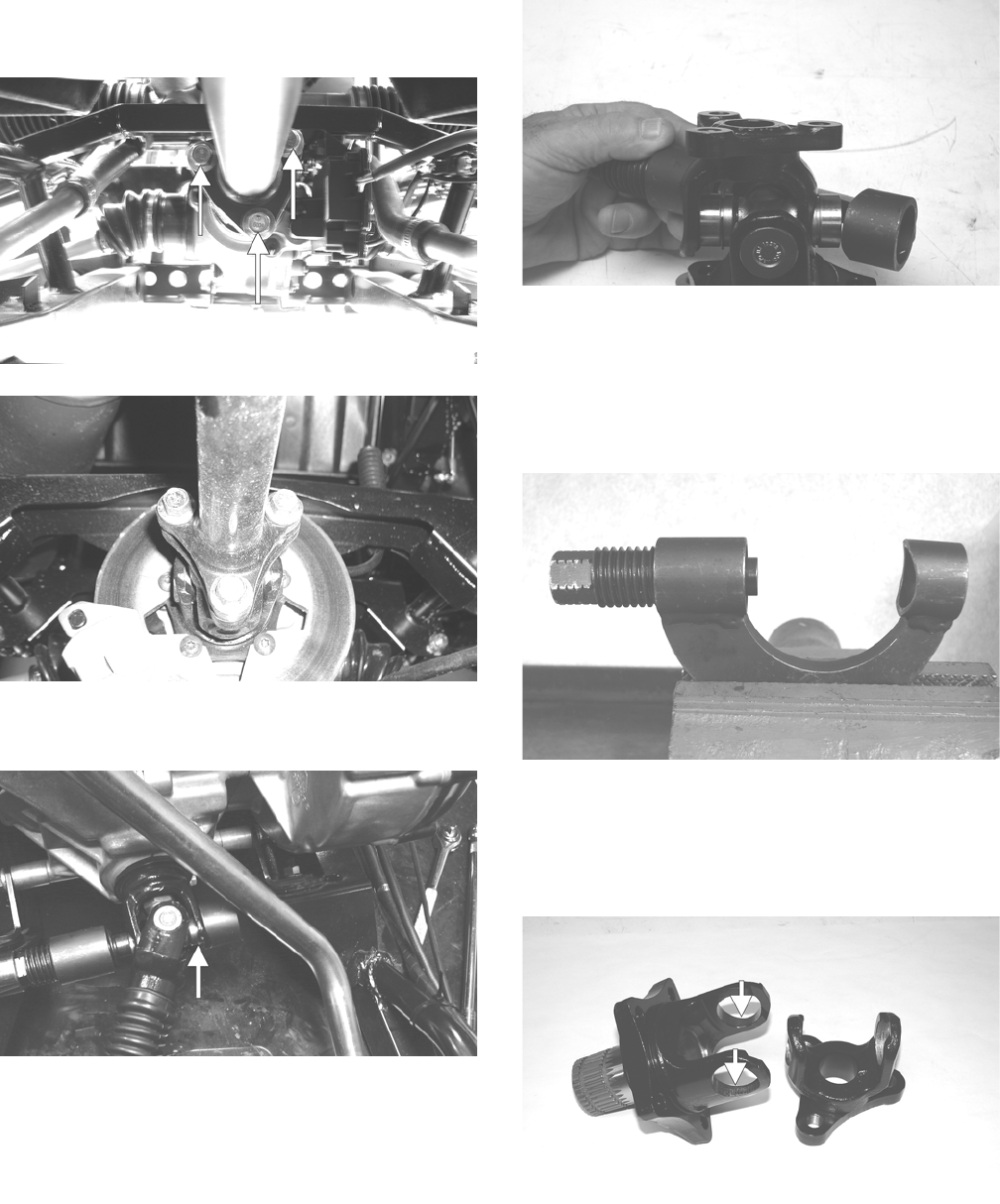
206
3. Remove the cap screws securing the propeller shaft
flange to the yoke flange on the appropriate
drive-line; then remove the propeller shaft.
PR120A
PR121
4. Install U-Joint Separator Tool on the universal joint
fixed yoke; then remove the bearing cup retainers.
PR354A
5. Using a suitable socket and ratchet handle, rotate the
jackscrew to push the bearing cup out of the yoke;
then remove the tool and the bearing cup.
PR359
6. Install the separator tool on the opposite side of the
yoke to push the second bearing cup from the yoke;
then remove the tool and separate the universal joint.
7. Secure the separator tool in a vise and repeat steps
4-6 to remove the bearing cups from the movable
yoke.
PR375
INSPECTING
1. Inspect the yoke bores for damage or signs of bear-
ing cup looseness. If bearing cups are loose, the yoke
must be replaced.
PR367B
2. Check that yoke legs are parallel.
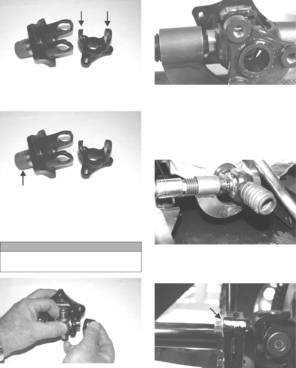
207
PR367A
3. Check splines and flanges for excessive wear, thread
damage, or warpage.
PR367C
INSTALLING
1. Remove the bearing cups from the universal joint;
then insert the joint into the yoke and install one
bearing cup on the joint.
PR368
2. Secure U-Joint Separator Tool in a vise; then place
the yoke, joint, and bearing cup into position and
press the cup into the yoke.
PR374
3. Install the retainer in the bearing cup; then remove
the yoke from the separator tool.
NOTE: Repeat steps 2-3 for the opposite-side bear-
ing cup.
4. Remove the separator tool from the vise and install
the universal joint, bearing cups, and movable yoke
into the fixed yoke using the same procedure as steps
2-3 except the vise cannot be used.
PR355
5. Check that the universal joint can be flexed freely
without binding; then apply multi-purpose grease to
the splines and install the propeller shaft noting the
match marks made prior to removing.
PR152A
CAUTION
Care must be taken when installing bearing cups that
the needle bearings stay in place or severe damage to
the universal joint will occur.

208
Troubleshooting Drive
System
Troubleshooting Brake
System
Problem: Power not transmitted from engine to wheels
Condition Remedy
1. Rear axle shaft serration worn - broken 1. Replace shaft
Problem: Power not transmitted from engine to either front wheel
Condition Remedy
1. Secondary drive - driven gear teeth broken
2. Propeller shaft serration worn - broken
3. Coupling damaged
4. Coupling joint serration worn - damaged
5. Front drive - driven bevel gears broken - damaged
6. Front differential gears/pinions broken - damaged
7. Front drive actuator not operating
1. Replace gear(s)
2. Replace shaft
3. Replace coupling
4. Replace joint
5. Replace gear(s)
6. Replace gears - pinions
7. Replace fuse - drive select switch - front drive actuator
Problem: Braking poor
Condition Remedy
1. Pad worn
2. Brake fluid leaking
3. Master cylinder/brake cylinder seal worn
1. Replace pads
2. Repair leak(s)
3. Replace seal(s)
Problem: Brake pedal travel excessive
Condition Remedy
1. Brake fluid low
2. Piston seal - cup worn
1. Add fluid to proper level
2. Replace seal - cup
Problem: Brake fluid leaking
Condition Remedy
1. Fittings loose
2. Hose cracked
3. Piston seal worn
1. Tighten fittings
2. Replace hose
3. Replace seal
Problem: Brake pedal spongy
Condition Remedy
1. Air trapped in hydraulic system
2. Brake fluid low
1. Bleed hydraulic system
2. Add brake fluid and bleed hydraulic brake system
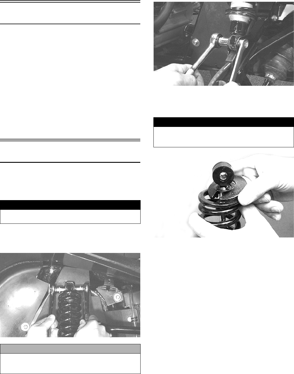
209
Suspension
The following suspension system components should be
inspected periodically to ensure proper operation.
A. Shock absorber rods bent, pitted, or damaged.
B. Rubber damper cracked, broken, or missing.
C. Shock absorber body damaged, punctured, or
leaking.
D. Shock absorber eyelets broken, bent, or cracked.
E. Shock absorber eyelet bushings worn, deterio-
rated, cracked, or missing.
F. Shock absorber spring broken or sagging.
G. Sway bar mountings tight and bushings secure.
Shock Absorbers
REMOVING
1. Secure the vehicle on a support stand to elevate the
wheels and to release load on the suspension.
2. Remove the two cap screws and nuts securing each
front shock absorber to the frame and upper A-arm.
Account for bushings and sleeves from each.
AF605D
3. Remove the two cap screws and nut securing each rear
shock absorber to the frame and lower A-arm.
Account for bushings and sleeves from each.
AF626D
4. Using a suitable spring compression stand, compress
the shock absorber spring, remove the retainer, and
remove the spring.
AF730D
CLEANING AND INSPECTING
1. Clean all shock absorber components in parts-clean-
ing solvent.
2. Inspect each shock rod for nicks, pits, rust, bends,
and oily residue.
3. Inspect all springs, spring retainers, shock rods,
sleeves, bushings, shock bodies, and eyelets for
cracks, leaks, and bends.
INSTALLING
1. Place the shock absorber spring over the shock absorber,
compress the spring, and install the retainer.
2. Place bushings and sleeves (where appropriate) into shock
eyelet; then install shocks with two cap screws and nuts.
3. On the XT/XTX, tighten the front shock absorber cap
screws to 35 ft-lb and the rear shock absorber cap screws
to 35 ft-lb (upper) or 20 ft-lb (lower). On the XTZ, tighten
the front and rear shock absorber cap screws to 35 ft-lb.
4. Remove the vehicle from the support stand.
! WARNING
Make sure the vehicle is solidly supported on the sup-
port stand to avoid injury.
CAUTION
Additional support stands are necessary to support the
rear axle when the shock absorbers are removed or
damage may occur.
! WARNING
Shock absorber springs are under high compression
loads. Do not attempt to remove springs without an ade-
quate spring compressor. Sever injury could result.
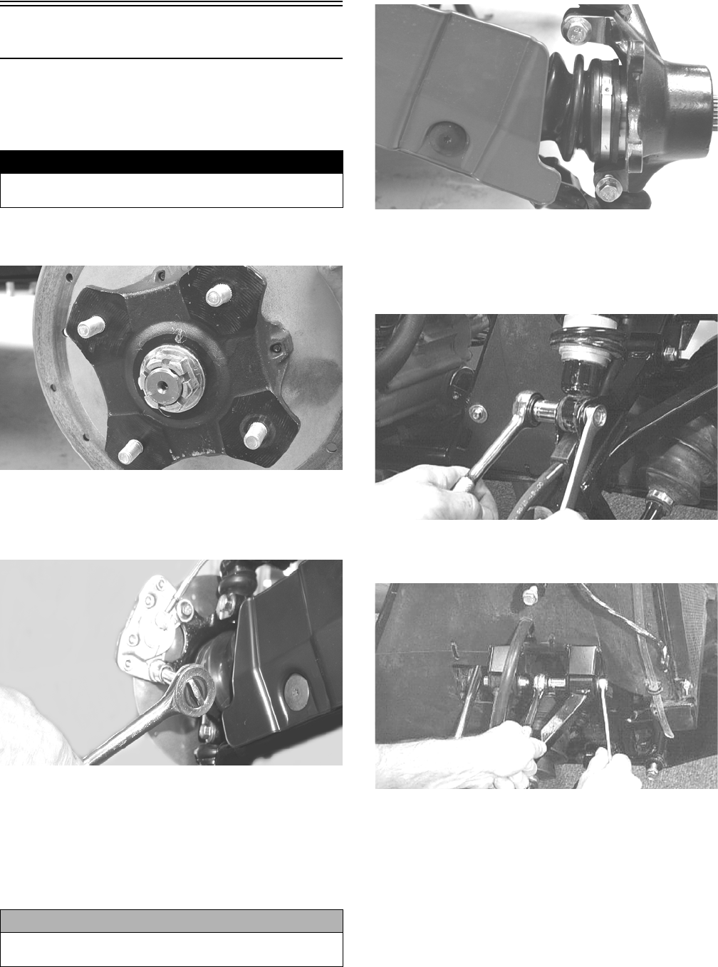
210
Front A-Arms
REMOVING
1. Secure the vehicle on a support stand to elevate the
front wheels; then remove the wheels.
2. Remove the cotter pin from the nut. Discard the cot-
ter pin.
PR257
3. Remove the nut securing the hub.
4. Remove the brake caliper. Account for two cap
screws.
CD007
5. Remove the hub assembly.
6. Remove the cotter pin and slotted nut securing the tie
rod end to the knuckle; then remove the tie rod end
from the knuckle.
7. Remove the cap screws securing the ball joints to the
knuckle.
PR193
8. Tap the ball joints out of the knuckle; then remove
the knuckle.
9. Remove the lower shock absorber eyelet from the
upper A-arm.
AF626D
10. Remove the cap screws securing the A-arms to the
frame.
AF610D
11. Remove the snap ring from the ball joint; then
remove the ball joint from the A-arm.
! WARNING
Make sure the vehicle is solidly supported on the sup-
port stand to avoid injury.
CAUTION
Support the knuckle when removing the cap screws or
damage to the threads will occur.
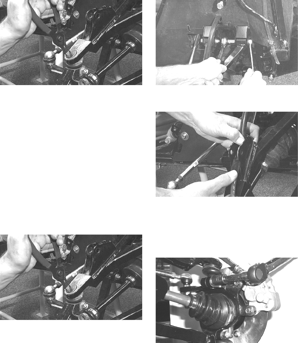
211
AF616D
CLEANING AND INSPECTING
1. Clean all A-arm components in parts-cleaning sol-
vent.
2. Clean the ball joint mounting hole of all residual
Loctite, grease, oil, or dirt for installing purposes.
3. Inspect the A-arm for bends, cracks, and worn bush-
ings.
4. Inspect the ball joint mounting holes for cracks or
damage.
5. Inspect the frame mounts for signs of damage, wear,
or weldment damage.
INSTALLING
1. Apply Loctite Primer “T” to the A-arm socket; then
apply green Loctite #609 to the entire outside diame-
ter of the ball joint. Install the ball joint into the
A-arm and secure with the snap ring.
AF616D
2. Install the A-arm assemblies into the frame mounts
and secure with the cap screws. Only finger-tighten
at this time.
AF610D
3. Route the brake hose through the upper A-arm shock
absorber mount.
AF627D
4. Secure the lower eyelet of the shock absorber to the
upper A-arm. Tighten nut to 35 ft-lb.
5. Secure the A-arm assemblies to the frame mounts
(from step 2). Tighten the cap screws to 35 ft-lb.
6. Install the knuckle assembly onto the ball joints and
secure with cap screws. Tighten to 35 ft-lb.
AF628D
7. Install the tie rod end and secure with the nut (coated
with red Loctite #271). Tighten to 30 ft-lb; then
install a new cotter pin and spread the pin to secure
the nut.
NOTE: During assembly, new cotter pins should be
installed.
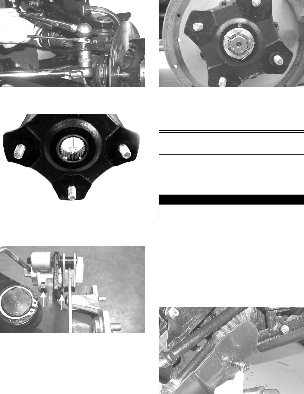
212
AF618D
8. Apply grease to the hub and drive axle splines; then
install the hub assembly onto the drive axle.
PR290A
9. Secure the hub assembly with the nut. Tighten only
until snug.
10. Secure the brake caliper to the knuckle with two new
“patch-lock” cap screws. Tighten to 20 ft-lb.
PR377B
11. Secure the hub nut (from step 9) to the shaft/axle.
Tighten to 200 ft-lb.
12. Install a new cotter pin and spread the pin to secure
the nut.
NOTE: If the cotter pin cannot be inserted due to
misalignment of the hole in the axle and the slots in
the nut, tighten the nut until properly aligned.
PR260
13. Install the wheel and tighten in a crisscross pattern in
20 ft-lb increments to 80 ft-lb (aluminum wheels) or
45 ft-lb (steel wheels).
14. Remove the vehicle from the support stand.
Rear A-Arms
REMOVING
1. Secure the vehicle on a support stand to elevate the
wheels.
2. Set the parking brake.
3. Remove the wheel.
4. Remove the cotter pin securing the hex nut; then
remove the hex nut.
5. Remove the cap screws and lock nut securing the
shock absorber to the frame and lower A-arm; then
remove the shock absorber.
6. Remove the cap screws securing the boot guard to
the lower A-arm.
AF934
7. Slide the axle out of the knuckle and set aside.
8. Remove the cap screws and lock nuts securing the
knuckle to the A-arms. Discard the lock nuts.
! WARNING
Make sure the vehicle is solidly supported on the sup-
port stand to avoid injury.
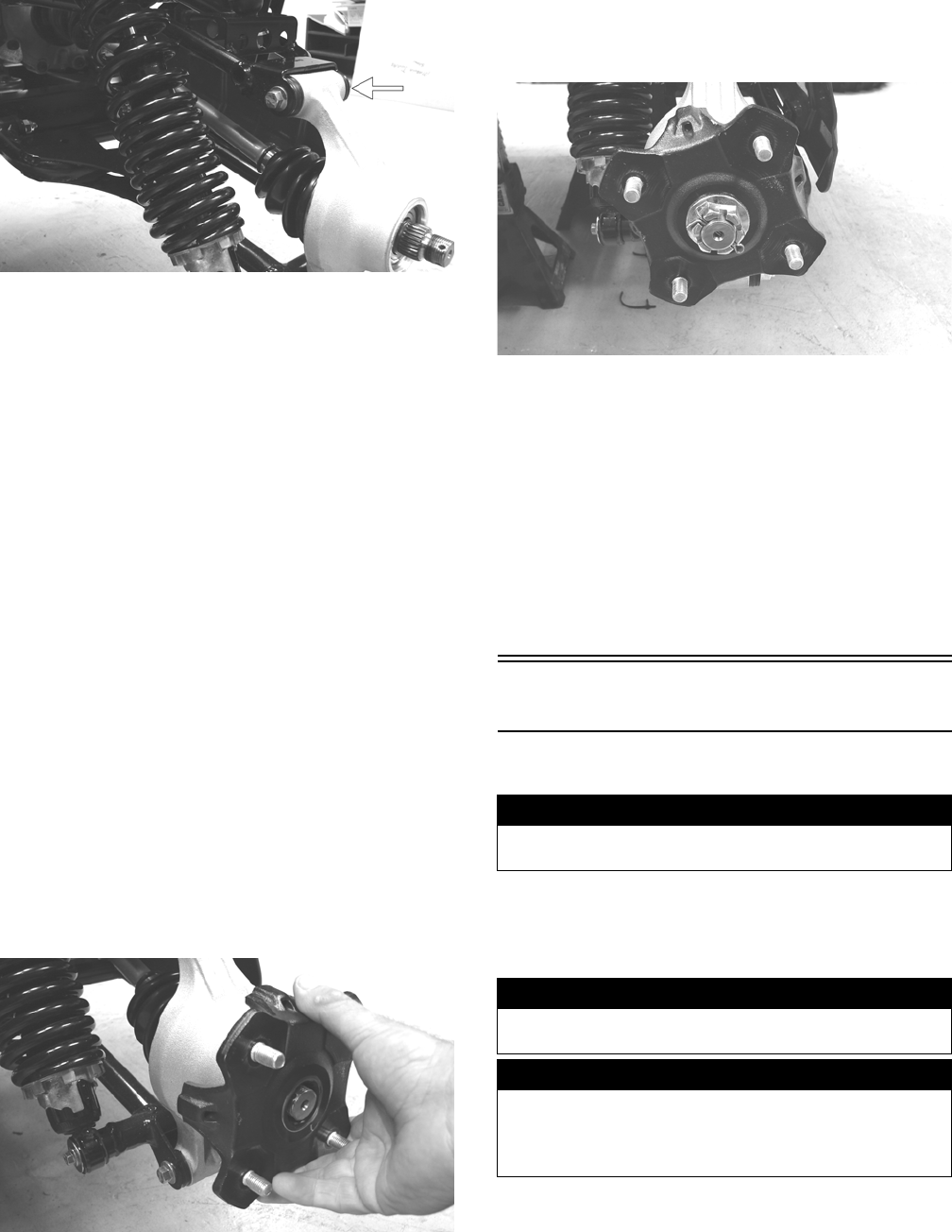
213
PR220A
NOTE: Never reuse a lock nut. Once a lock nut has
been removed, it must be replaced with a new lock
nut.
9. Remove the cap screws and lock nuts securing the
A-arms to the frame; then remove the A-arms.
CLEANING AND INSPECTING
1. Clean all A-arm components in parts-cleaning sol-
vent.
2. Inspect the A-arm for bends, cracks, and worn bush-
ings.
3. Inspect the frame mounts for signs of damage, wear,
or weldment damage.
INSTALLING
1. Install the A-arm assemblies into the frame mounts
and secure with the cap screws and new lock nuts.
Finger-tighten only at this time.
2. Slide the knuckle onto the drive axle and into posi-
tion on the A-arms; then secure the knuckle to the
A-arms with cap screws and new lock nuts. Tighten
to 35 ft-lb.
3. Tighten the hardware securing the A-arms to the
frame mounts (from step 1) to 35 ft-lb.
4. Apply grease on the drive axle splines; then install
the hub assembly onto the drive axle.
PR221
5. Secure the hub assembly with the nut. Tighten to 200
ft-lb.
6. Install a new cotter pin and spread the pin to secure
the nut.
NOTE: If the cotter pin cannot be inserted due to
misalignment of the hole in the axle and the slots in
the nut, tighten the nut until properly aligned.
PR196
7. Secure the shock absorber to the frame with a cap
screw and new lock nut. Tighten to 33 ft-lb.
8. Secure the shock absorber to the lower A-arm with a
cap screw and new lock nut. Tighten to 20 ft-lb.
9. Secure the boot guard to the lower A-arm with the
two cap screws. Tighten securely.
10. Install the wheel and tighten in a crisscross pattern in
20 ft-lb increments to 80 ft-lb (aluminum wheels) or
45 ft-lb (steel wheels).
11. Remove the vehicle from the support stand.
Wheels and Tires
TIRE SIZE
The ROV models are equipped with low-pressure tube-
less tires of the size and type listed in the General Infor-
mation section. Do not under any circumstances
substitute tires of a different type or size.
TIRE INFLATION PRESSURE
Front and rear tire inflation pressure should be 0.84-1.41
kg/cm2 (12-20 psi).
! WARNING
Use only Arctic Cat approved tires when replacing tires.
Failure to do so could result in unstable vehicle operation.
! WARNING
Always use the size and type of tires specified. Always
maintain proper tire inflation pressure.
! WARNING
Do not mix tire tread patterns. Use the same pattern type
on front and rear. Failure to heed warning could cause
poor handling qualities of the vehicle and could cause
excessive drive train damage not covered by warranty.

214
REMOVING
1. Secure the vehicle on a support stand to elevate the
wheels.
2. Remove the nuts securing the wheels; then remove
the wheels.
CLEANING AND INSPECTING
1. Clean the wheels and hubs with parts-cleaning sol-
vent.
2. Clean the tires with soap and water.
3. Inspect each wheel for cracks, dents, or bends.
4. Inspect each tire for cuts, wear, missing lugs, and
leaks.
INSTALLING
1. Install each wheel on its hub and secure with the
existing hardware.
2. Tighten in a crisscross pattern in 20 ft-lb increments
to 80 ft-lb (aluminum wheels) or 45 ft-lb (steel
wheels).
CHECKING/INFLATING
1. Using an air pressure gauge, measure the air pressure
in each tire. Adjust the air pressure as necessary to
meet the recommended inflation pressure.
2. Inspect the tires for damage, wear, or punctures.
NOTE: If repair is needed, follow the instructions
found on the tire repair kit or remove the wheel and
have it repaired professionally.
NOTE: Be sure all tires are the specified size and
have identical tread pattern.
Troubleshooting
! WARNING
Make sure the vehicle is solidly supported on the sup-
port stand to avoid injury.
! WARNING
Do not operate the vehicle if tire damage exists.
Problem: Suspension too soft
Condition Remedy
1. Spring preload incorrect
2. Spring(s) weak
3. Shock absorber damaged
1. Adjust preload
2. Replace spring(s)
3. Replace shock absorber
Problem: Suspension too stiff
Condition Remedy
1. Spring preload incorrect
2. A-arm-related bushings worn
1. Adjust preload
2. Replace bushing
Problem: Suspension noisy
Condition Remedy
1. Cap screws (suspension system) loose
2. A-arm-related bushings worn
1. Tighten cap screws
2. Replace bushings
Problem: Vehicle pulling or steering erratic
Condition Remedy
1. Vehicle steering is erratic on dry, level surface
2. Vehicle pulls left or right on dry, level surface
1. Check front wheel alignment and adjust if necessary (see
the Steering/Frame/Controls section)
2. Check air pressure in tires and adjust to specifications

Printed in U.S.A. Trademarks of Arctic Cat Inc., Thief River Falls, MN 56701 p/n 2259-857
