235 Sensormodules 08905072A User Manual Sensor Modules
238 Sensormodules 238_SensorModules 238_SensorModules Xantech-Discontinued-Manuals products corebrands-resources
240 Sensormodules 240_SensorModules 240_SensorModules Xantech-Discontinued-Manuals products corebrands-resources
239 Sensormodules 239_SensorModules 239_SensorModules Xantech-Discontinued-Manuals products corebrands-resources
237 Sensormodules 237_SensorModules 237_SensorModules Xantech-Discontinued-Manuals products corebrands-resources
2017-11-15
User Manual: Manual 235 Sensormodules 235_SensorModules Xantech-Discontinued-Manuals products
Open the PDF directly: View PDF ![]() .
.
Page Count: 8

- 1 -
INSTALLATION INSTRUCTIONS
Sensor Modules
SMAUD01, SMVID01, SMMAG01, SMLIT01, SMCC01, SMVLT01
DESCRIPTION
The Xantech Sensor Module product line provides several sensing solutions for a wide variety of
automation needs. Used in conjunction with Xantech’s award winning MRC platform*, source
management and control is easy and reliable. Also, the sensor modules can be used with the
CBCSM1 connecting block to provide a simple interface solution. The CBCSM1 can provide positive
and negative logic through its PULL UP and PULL DOWN connections.
(* MRC44, MRAUDIO4X4, MRC88, MRAUDIO8X8)
The Xantech Sensor Module product line is composed of six complete, easy to install packages.
SMAUD01 Audio Sensor Module
SMVID01 Video Sensor Module
SMMAG01 Magnetic and Current Sensor Module
SMLIT01 LED and Light Sensor Module
SMCC01 Contact Closure Sensor Module
SMVLT01 AC\DC Voltage Sensor Module
Each module comes with double-sided foam tape and mounting screws. Also, built into the sensor is
a convenient LED light that turns ‘on’ to indicate the sensor is in an ‘on’ condition.
SPECIFICATIONS
Delay: Adjustable between 0 and 15 seconds.
+12VDC, <50mA.
1/8” (3.5mm) mini-plug, Tip: +12VDC, Ring: Signal, Sleeve: Ground.
Sensor Module Dimensions: 3/4” W x 3 3/4” L x 3/4” H.
Control Cable Length: Approx. 6 feet
Sensor Cable** Length: 6.5’ SMAUD01, SMVID01
Sensor Cable** Length: 5.0’ SMMAG01, SMLIT01
(** not applicable on the SMCC01, SMVLT01)
Xantech Corporation
13100 Telfair Avenue, 2/F
Sylmar, CA 91342
Installation Instructions, Sensor Modules
© 2006 Xantech Corporation, Document #08905072A
This document is copyright protected. No part of this manual may be copied or reproduced in any form without prior written consent from Xantech
Corporation.
Xantech Corporation shall not be liable for operational, technical, or editorial errors/omissions made in this document.
- 2 -
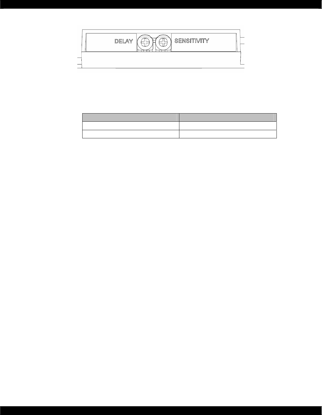
ADJUSTMENTS
Each sensor module has an adjustment for delay (between 0 and 15 seconds). The delay adjustment
determines the amount of time the sensor module remains “on” after the stimulus condition stops. For
instance, when SMVLT01 no longer sees a voltage that stimulated the sensor to the “on” condition,
the delay will determine when the sensor returns to the “off” condition.
Increase Decrease
Delay Clockwise Counter-Clockwise
Sensitivity Clockwise Counter-Clockwise
The sensitivity adjustment is found on all sensor modules except the SMCC01 and SMVLT01.
Increasing the sensitivity will make the sensor easier to ‘trip’. Decreasing the sensitivity makes the
sensor harder to ‘trip’.
- 3 -
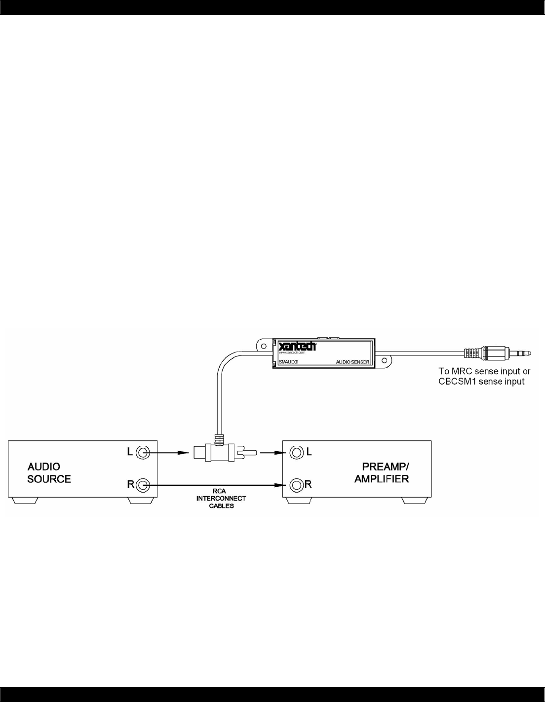
INSTALLATION – SMAUD01: Audio Sensor Module
The SMAUD01 sensor module provides status feedback by monitoring the line-level audio
connection. The sensor head is placed in between and input and output audio signal. For instance,
the sensor head is placed between an amplifier and a CD player on either the right or left channel
audio cable.
SMAUD01 is intended for line-level signals only. Do not use with amplifier outputs or speaker volume
controls.
(1) Plug the 1/8” (3.5mm) mini-plug into the sensing controller (CBCSM1 and MRC platform
provides power to the sensor module). Sensing controller power should be off.
(2) Connect the sensor head on the output of the audio source.
(3) Connect the audio cables as you would normally do.
(4) Turn on the audio source output. (i.e. ‘play’ button on a CD player)
(5) Verify the SMAUD01 LED indicator is ‘on’.
(6) Turn off the audio source output. (i.e. ‘stop’ button on a CD player)
(7) Verify the SMAUD01 LED indicator is ‘off’.
(8) If the indicator is not ‘off’, then adjust the sensitivity until the LED just turns off.
(9) Repeat Steps 4 to 8 until both ‘on’ and ‘off’ conditions are satisfied.
- 4 -
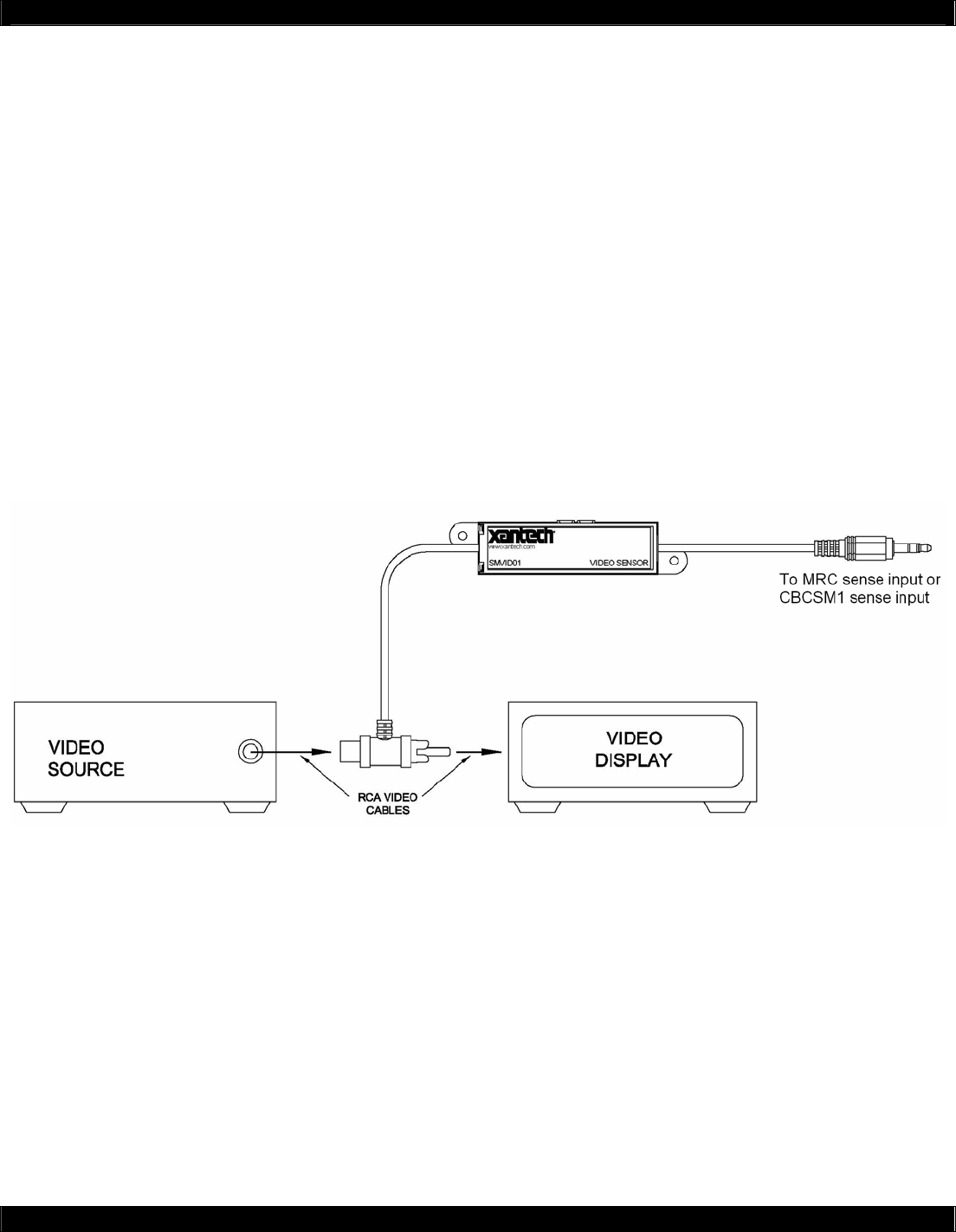
INSTALLATION – SMVID01: Video Sensor Module
The SMVID01 sensor module provides status feedback by monitoring the composite video
connection. The sensor head is placed in between and input and output video signal. For instance,
the sensor head is placed between a video display and a DVD player on the composite video cable.
(1) Plug the 1/8” (3.5mm) mini-plug into the sensing controller (CBCSM1 and MRC platform
provides power to the sensor module). Sensing controller power should be off.
(2) Connect the sensor head on the output of the video source.
(3) Connect the video cables as you would normally do.
(4) Turn on the video source output. (i.e. ‘power on’ button on a DVD player)
(5) Verify the SMVID01 LED indicator is ‘on’.
(6) Turn off the video source output. (i.e. ‘power off’ button on a DVD player)
(7) Verify the SMVID01 LED indicator is ‘off’.
(8) If the indicator is not ‘off’, then adjust the sensitivity until the LED just turns off.
(9) Repeat Steps 4 to 8 until both ‘on’ and ‘off’ conditions are satisfied.
- 5 -
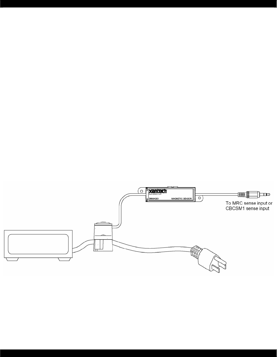
INSTALLATION – SMMAG01: Magnetic and Current Sensor Module
The SMMAG01 sensor module provides status feedback by monitoring the AC current in power cords
of the AC magnetic fields from CRT monitor and motors. For AC current in power cords, the sensor
head is placed on the actual power cord. No power cord stripping or cutting is required. For AC
magnetic fields, the base is removed and the sensor head is placed near the AC magnetic field
source.
The sensor head comes with an insert that is placed between the head and the base. This insert
allows the use of various power cord sizes and shapes, such as flat “lamp” cords.
Power Cord Application
(1) Plug the 1/8” (3.5mm) mini-plug into the sensing controller (CBCSM1 and MRC platform
provides power to the sensor module). Sensing controller power should be off.
(2) Place the sensor head on the power cord.
(3) Connect the power cord as you would normally do.
(4) Turn on the device connected to the power cord and power the device ‘on’.
(5) Verify the SMMAG01 LED indicator is ‘on’.
(6) Turn off the device connected to the power cord and power the device ‘off’.
(7) Verify the SMMAG01 LED indicator is ‘off’.
(8) If the indicator is not ‘off’, then adjust the sensitivity until the LED just turns off.
(9) Repeat Steps 4 to 8 until both ‘on’ and ‘off’ conditions are satisfied.
Magnetic Field Application
(1) Plug the 1/8” (3.5mm) mini-plug into the sensing controller (CBCSM1 and MRC platform
provides power to the sensor module). Sensing controller power should be off.
(2) Place the sensor head near the magnetic field source.
(3) Generate the magnetic field source. (i.e. CRT monitor or motor ‘on’)
(4) Verify the SMMAG01 LED indicator is ‘on’.
(5) Turn off the magnetic field source. (i.e. CRT monitor or motor ‘off’)
(6) Verify the SMMAG01 LED indicator is ‘off’.
(7) If the indicator is not ‘off’, then adjust the sensitivity until the LED just turns off.
(8) Repeat Steps 4 to 8 until both ‘on’ and ‘off’ conditions are satisfied.
- 6 -
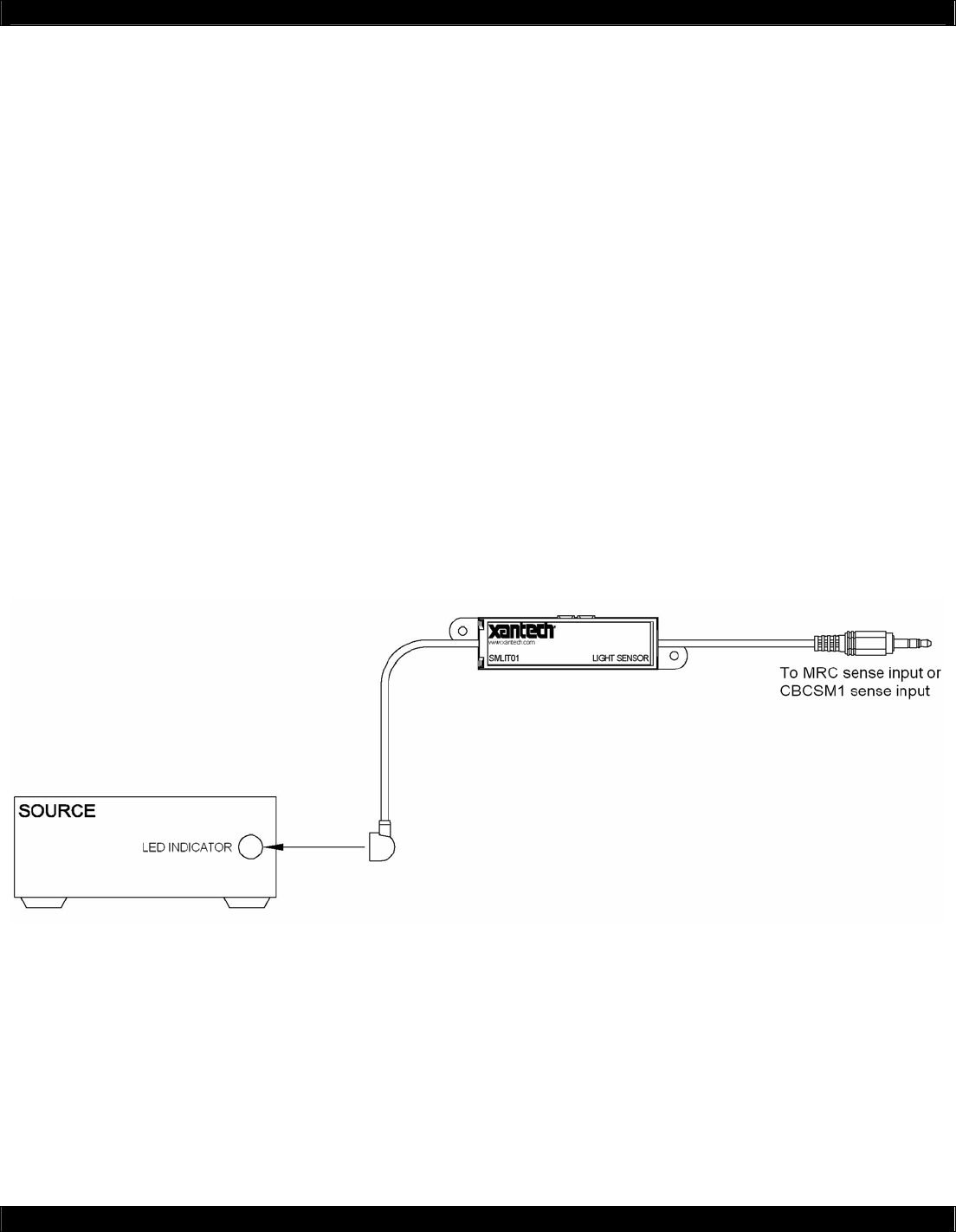
INSTALLATION – SMLIT01: LED and Light Sensor Module
The SMLIT01 sensor module provides status feedback by monitoring the light or LED indicators
found on a majority of electronic equipment. The sensor head is placed on top of the light or LED
indicator. For instance, the sensor head is placed on top of the power ‘pilot light’ LED of a DVD
player. Or, the sensor head can be placed on top of the “tuned” LED of a digital AM/FM tuner. The
SMLIT01 can also detect room light and daylight.
Colored filters are included for even more advance applications. A red colored filter can be used to
detect red LED lamps only. A green colored filter can be used to detect green LED lamps only.
(1) Plug the 1/8” (3.5mm) mini-plug into the sensing controller (CBCSM1 and MRC platform
provides power to the sensor module). Sensing controller power should be off.
(2) Connect the sensor head on the output of the video source.
(3) Connect the video cables as you would normally do.
(4) Turn on the video source output. (i.e. ‘power on’ button on a DVD player)
(5) Verify the SMVID01 LED indicator is ‘on’.
(6) Turn off the video source output. (i.e. ‘power off’ button on a DVD player)
(7) Verify the SMVID01 LED indicator is ‘off’.
(8) If the indicator is not ‘off’, then adjust the sensitivity until the LED just turns off.
(9) Repeat Steps 4 to 8 until both ‘on’ and ‘off’ conditions are satisfied.
- 7 -
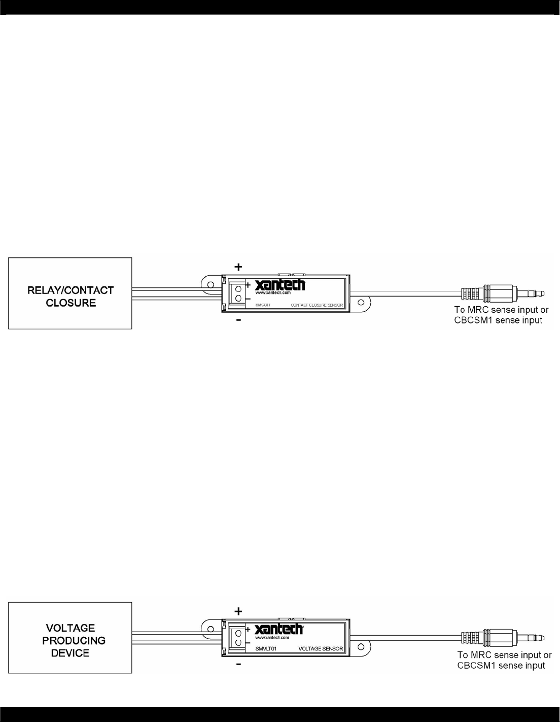
INSTALLATION – SMCC01: Contact Closure Sensor Module
The SMCC01 sensor module detects dry switch/relay closure. Two wires form a dry switch or relay
contacts can be connect to the screw terminals. When a switch or relay provides a ‘short’ between
the two wires, the sensor module is ‘on’. When the switch or relay provides an ‘open’ between the two
wires, the sensor module is ‘off’.
(1) Plug the 1/8” (3.5mm) mini-plug into the sensing controller (CBCSM1 and MRC platform
provides power to the sensor module). Sensing controller power should be off.
(2) Connect wires from the screw terminals to the switch or relay.
(3) Close the switch or relay to create a ‘short circuit’ between the screw terminals.
(4) Verify the SMCC01 LED indicator is ‘on’.
(5) Open the switch or replay to create an ‘open circuit’ between the screw terminals.
(6) Verify the SMCC01 LED indicator is ‘off’.
(7) If the indicator is not ‘off’, then adjust the sensitivity until the LED just turns off.
(8) Repeat Steps 4 to 8 until both ‘on’ and ‘off’ conditions are satisfied.
INSTALLATION – SMVLT01: AC\DC Voltage Sensor Module
The SMVLT01 sensor module detects AC or DC voltage between 9 to 24 volts. Two wires are
connected from the voltage generating source to the sensor module. For instance, a 781RG +12Vdc
power supply can be connected to the switch outlet of a common stereo receiver. The output of the
781RG is connected to the SMVLT01. When the stereo receiver is on, the SMVLT01 turns on.
Another application is to ‘tap’ onto the doorbell ringer. When the doorbell is energized, the SMVLT01
will detect the voltage and turns on.
(1) Plug the 1/8” (3.5mm) mini-plug into the sensing controller (CBCSM1 and MRC platform
provides power to the sensor module). Sensing controller power should be off.
(2) Connect wires from the screw terminals to the voltage source.
(3) Turn on the power source. (i.e. press doorbell button or turn on stereo receiver)
(4) Verify the SMVLT01 LED indicator is ‘on’.
(5) Turn off the power source. (i.e. depress doorbell button or turn off stereo receiver)
(6) Verify the SMVLT01 LED indicator is ‘off’.
(7) If the indicator is not ‘off’, then adjust the sensitivity until the LED just turns off.
(8) Repeat Steps 4 to 8 until both ‘on’ and ‘off’ conditions are satisfied.
- 8 -
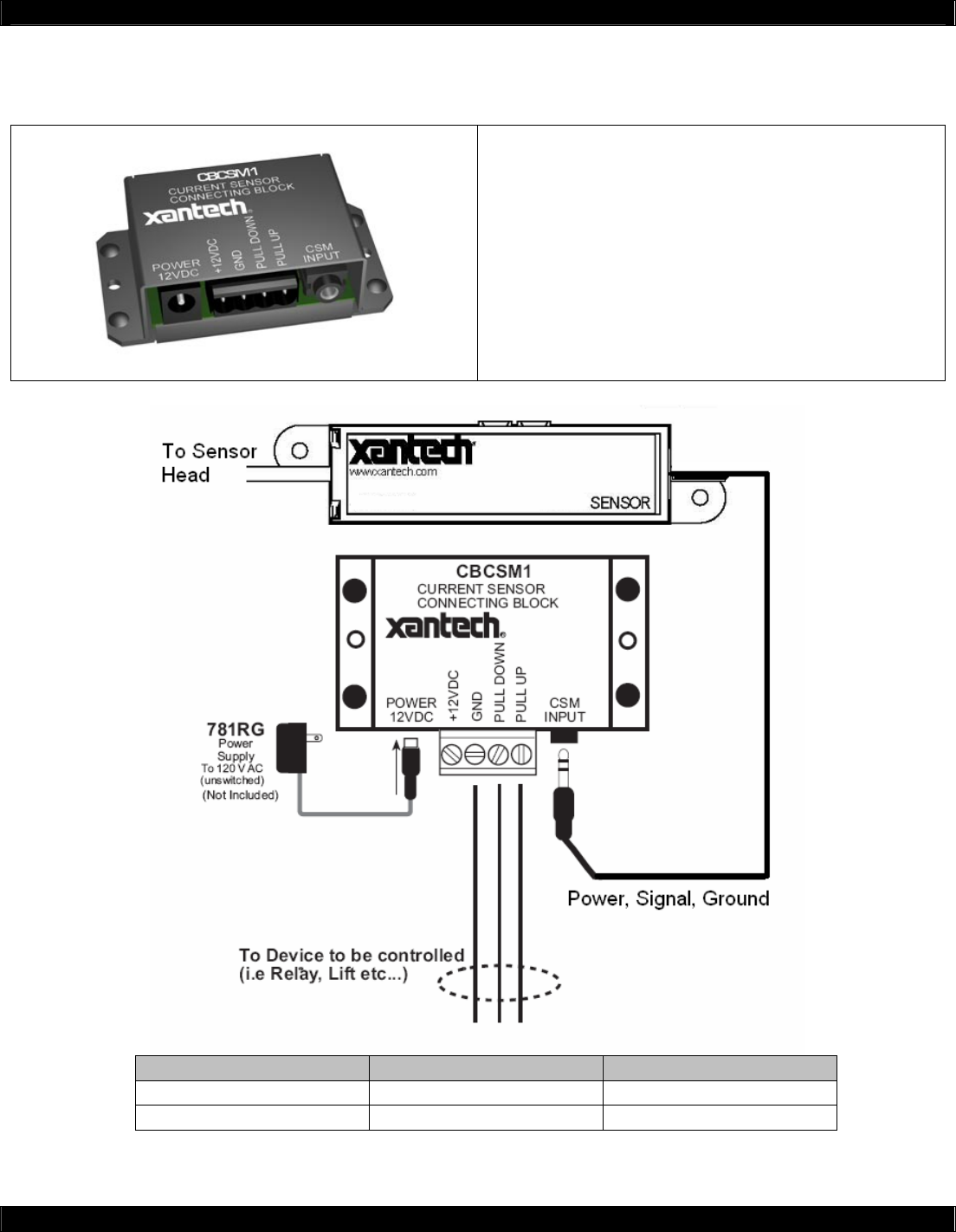
CBCSM1 CSM1 Current Sensor Connecting Block
FEATURES
The CBCSM1 allows the Xantech CSM1 Current Sensor
to be used as a general purpose current sensor to sense
the power state of a component by detecting the
difference in current drawn by the component when it is
either ON or OFF and to generate a status signal that can
be used to control other equipment.
• Requires a CSM1 Current Sensor
• Requires a 781RG Power Supply
Sensor State Pull Up Voltage Pull Down Voltage
ON +12 VDC (HIGH) +0 VDC (LOW)
OFF +0 VDC (LOW) +12 VDC (HIGH)
