590 Mx88Manual INSTALLATION INSTRUCTIONS User Manual
Xantech-Stereo-Amplifier-Mx88-Users-Manual-473474 xantech-stereo-amplifier-mx88-users-manual-473474
MX88 to the manual 1227e0e5-c551-40a6-ab75-db47cd7f86d5
2017-11-15
User Manual: Manual 590 Mx88Manual 590_MX88Manual Xantech-Discontinued-Manuals products
Open the PDF directly: View PDF ![]() .
.
Page Count: 44

INSTALLATION INSTRUCTIONS
MX88
EIGHT ZONE – EIGHT SOURCE
AUDIO & AUDIO/VIDEO CONTROLLER/AMPLIFIER
Page: 2 Model MX88
© 2011 Xantech Corporation
IMPORTANT SAFETY INSTRUCTIONS - READ BEFORE OPERATING EQUIPMENT
CAUTION: TO REDUCE THE RISK OF ELECTRIC SHOCK,
DO NOT REMOVE COVER (OR BACK)
NO USER-SERVICEABLE PARTS INSIDE
REFER SERVICING TO QUALIFIED SERVICE PERSONNEL
The lightning flash with arrowhead symbol, within an equilateral triangle,
is intended to alert the user to the presence of un-insulated “dangerous
voltage” within the product‟s enclosure that may be of sufficient magnitude
to constitute a risk of electric shock to persons.
The exclamation point within an equilateral triangle is intended to alert the
user to the presence of important operating and maintenance (servicing)
instructions in the literature accompanying the appliance.
WARNING
TO REDUCE THE RISK OF FIRE OR ELECTRIC SHOCK, DO
NOT EXPOSE THIS APPLIANCE TO RAIN OR MOISTURE.
This product was designed and manufactured to meet strict quality and safety standards. There are, however,
some installation and operation precautions, which you should be particularly aware of.
1. Read Instructions – All the safety and operating instructions should be read before the appliance is operated.
2. Retain Instructions – The safety and operating instructions should be retained for future reference.
3. Heed Warnings – All warnings on the appliance and in the operating instructions should be adhered to.
4. Follow Instructions – All operating and use instructions should be followed.
5. Water and Moisture – The appliance should not be used near water – for example, near a bathtub, washbowl, kitchen sink, laundry
tub, in a wet basement, or near a swimming pool, etc.
6. Carts and Stands – The appliance should be used only with a cart or stand that is recommended by the manufacturer. An appliance
and cart combination should be moved with care. Quick stops, excessive force, and uneven surfaces may cause the appliance and
cart combination to overturn.
7. Wall or Ceiling Mounting – The appliance should be mounted to a wall or ceiling only as recommended by the manufacturer.
8. Ventilation – The appliance should be situated so that its location or position does not interfere with its proper ventilation. For
example, the appliance should not be situated on a bed, sofa, rug, or similar surface that may block the ventilation openings; or,
placed in a built-in installation, such as a bookcase or cabinet that may impede the flow of air through the ventilation openings.
9. Heat – Do not install near any heat sources such as radiators, heat registers, stoves, or other apparatus (including amplifiers) that
produce heat.
10. Power Sources – The appliance should be connected to a power supply only of the type described in the operating instructions or as
marked on the appliance.
11. Grounding or Polarization – Do not defeat the safety purpose of the polarized or grounding-type plug. A polarized plug has two
blades with one wider than the other. A grounding type plug has two blades and a third grounding prong. The wide blade or the third
grounding prong are provided for your safety. If the provided plug does not fit into your outlet, consult an electrician for replacement of
the obsolete outlet.
12. Power-Cord Protection – Power- supply cords should be routed so that they are not likely to be walked on or pinched by items
placed upon or against them, paying particular attention to cords at plugs, convenience receptacles, and the point where they exit from
the appliance.
Model MX88 Page: 3
© 2010 Xantech LLC
13. Cleaning – Clean only with dry cloth.
14. Power Lines – An outdoor antenna should be located away from the power lines.
15. Nonuse Periods – The power cord of the appliance should be unplugged from the outlet when left unused for a long period of time.
16. Accessories: Only use attachments/accessories specified by the manufacturer.
17. Object and Liquid Entry – Care should be taken so that objects do not fall and liquids are not spilled into the enclosure through
openings.
18. Damage Requiring Service – The appliance should be serviced by qualified service personnel when:
A. The Power-supply cord or the plug has been damaged; or
B. Objects have fallen, or liquid has spilled into the appliance; or
C. The appliance has been exposed to rain; or
D. The appliance does not appear to operate normally or exhibits a marked change in performance; or
E. The appliance has been dropped, or the enclosure damaged.
19. Servicing – The user should not attempt to service the appliance beyond that described in the operating instructions. All other
servicing should be referred to qualified service personnel.

Page: 4 Model MX88
© 2011 Xantech Corporation
Section 1: General Information & Features
GENERAL INFORMATION
The Xantech MX88 System sets a new standard in whole-house audio/video distribution, audio amplification,
and control/automation. The MX88 System consists of the MX88 controller/amplifier, keypads (such as
MRKP1/1E or MRKP2/2E) or touch-panels (such as the Xantech SmartPanel™) to control each zone, and
wireless or wired web-enabled devices such as the Apple® iPad® for controlling all zones and the entire
system. When combined with IR, RS232, or IP controlled (IP on select models only) meta-data-rich audio/video
sources and home automation components, the MX88 becomes a powerful system capable of controlling
virtually everything within a household.
The MX88 can be used as a stand-alone unit or in conjunction with another MX88 to provide 16 Zones of
A/V/Control distribution.
MX88 models include:
MX88vi: Audio/Video/Control distribution, IP-enabled
MX88ai: Audio/Control distribution, IP-enabled
MX88a: Audio/Control distribution (no IP)
Each MX88 package contains :
One MX88 Controller/Amplifier
Eight IR Emitters part no. 283D
One part no. 05913410 gray-colored DB9 male-to-female programming cable to connect to the RS232
serial port on your PC
Two part no. 05913665 DB15 male to DB9 female cables for connecting MX88 rear ports 1 and 2 to RS232
devices
One part no. 05913555 male DB15 to male DB15 cable with null modem for linking two MX88 Controllers in
Expansion Mode
Eight speaker WECO connector plugs
Two rack ears
Three sets of screws and washers for attaching the rack ears to MX88
One US AC Cord
One European AC Cord
One UK AC Cord
One Australia/New Zealand AC Cord
Companion products available for the MX88 (sold separately):
Keypads: MRKP1, MRKP1E, MRKP2, MRKP2E, MRC88KP/MRC88DJKP (limited availability)
Touch-panels: Xantech SmartPanel™ SP35G, (C)SP43, (C)SP70, (C)SPLCD39, (C)SPLCD64
MREM (simple card type remote – no programming required)
MRC44CB1 Connecting Block
CSM1 Current Sensing Module
RS2321X8 Router: Serial Router expanding a single MX88 RS232 output to 8 Serial Ports
Part no. 05913560: Black-colored DB9 male-to-male Null-Modem cable to connect to the RS232 serial port
of an external device (that requires a null-modem connection) to the MX88, through the DB15 to DB9
cables that are included withn the MX88.
ZAIP Zone Audio Input Kit: For use with Zone Audio Inputs. Send and Receive Stereo Audio over CAT5
External IR Receivers: Xantech IR Receiver models, such as DL/HL/ML/WL85, or DL/HL/ML/WL95

Model MX88 Page: 5
© 2010 Xantech LLC
IMPORTANT NOTES:
1. The MX88 System can be a single controller with keypads for up to Eight zones or two connected controllers
and keypads for up to Sixteen zones.
All the set up details for a MX88 are stored in a file called “Project”.
The MX88 can be set up without a PC, using the QuickConfig protocol, via the keypad or touchpanel connected
to the Zone 1 keypad port of the MX88. By using QuickConfig, you can set up an eight zone or an expanded 16
zone MX88 system without ever having to hook up a PC.
However, please note that Projects created by QuickConfig cannot be retrieved and/or edited in Universal
Dragon.
The MX88 can also be set up and customized using Xantech‟s Universal Dragon Windows® software.
There are two different setup modes in the Universal Dragon:
- The Advanced mode allows customization of system configuration for functions such as zone linking,
monitor lockout, unique IR programming by zone, etc.
- The Expanded mode allows programming of systems with more than eight zones using two linked
MX88 Controllers.
Each section of this manual will indicate which sections apply to the different programming modes and setups.
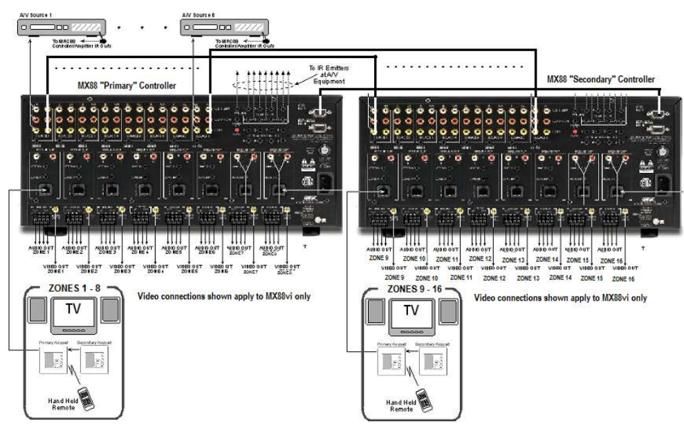
In the Expanded mode, the controller for zones 1-8 will be referred to as the PRIMARY CONTROLLER. The
controller for zones 9-16 will be referred to as the SECONDARY CONTROLLER.
2. All programming and features of the MX88 directly apply to all models except:
Video Distribution and Video Sensing applies to MX88vi models only
Ethernet/IP applies to MX88vi or MX88ai
Page: 6 Model MX88
© 2011 Xantech Corporation
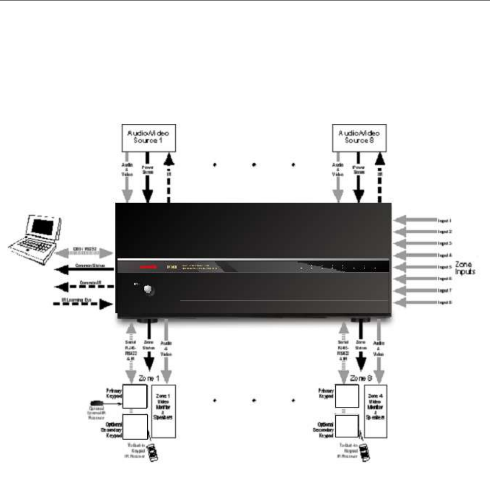
SYSTEM OVERVIEW
In a MX88-based whole house audio/video/control system, the MX88 controller/amplifier acts as the server and
the keypads, touch-panels, and compatible web-enabled devices (such as the Apple® iPad®) act as the clients.
The end users interact with these clients in order to control all aspects of audio/video distribution and control.
This system allows the end user to accomplish the following: 1) Distribute amplified audio and video from eight
independent Sources to eight separate zones. 2) Control the volume, mute, bass, treble, and balance for each
of the eight zones. 3) Control most standard source components via IR and/or RS232 and/or IP (certain MX88
models only) commands. Two MX88s can be linked to create systems with up to sixteen zones.
Figure 1 - System Block Diagram
There are many ways in which the MX88 can be controlled or to control audio, video and home control systems:
By pressing the buttons on the MX88 keypad or touch-panel
From signals received from an Infrared (IR) remote at the keypads IR Receiver eye
From RS232 control from a touch screen panel or other RS232 controller device
Model MX88 Page: 7
© 2010 Xantech LLC
Via IP (MX88vi amd MX88ai only), using almost any web-enabled device with a browser, such as an
Apple® iPad®, a Windows® or Android™ tablet, or a PC.
There are three types of commands that can be associated with the MX88 Keypad buttons:
Source component commands such as BluRay Player Power, Play, Track Skip, etc.
MX88 Controller/Amplifier “INTERNAL AMPLIFIER COMMANDS” such as Zone Source Select, Zone
Power, VOL+, VOL- etc.
RS232 Command Strings for controlling sophisticated control systems such as Lighting, HVAC, etc.
utilizing the MX88 Controller‟s RS232 COM PORT output
RS232-over-IP (MX88vi and MX88ai only) Command Strings for controlling sophisticated control
systems such as Lighting, HVAC, etc. utilizing the MX88 Controller‟s IP PORT – This feature is
currently in use on a very limited basis, and is reserved for future upgrades.

Page: 8 Model MX88
© 2011 Xantech Corporation
CONTROLLER/AMPLIFIER FEATURES
• Zones: Eight, expandable to sixteen-zones with the addition of a second MX88 and additional keypads
• Sources: Eight audio (MX88a or MX88ai) or eight audio/video (MX88vi). Any zone can select any source.
Any source can be selected in multiple zones. Several modes of control:
- Whole-house mode – selection and control of any source from any zone.
- Priority mode – any zone can select and monitor a source, but only the first zone to select that source
can control it.
- Link mode – multiple zones can be linked together to act as a single zone for source selection and
control. Each zone maintains independent volume and mute controls.
- Monitor lockout – prevents certain zones from selecting certain sources.
• Local Zone Audio Inputs: Eight zone-specific audio inputs. When activated, overrides source-one audio
inputs allowing each zone to have its own dedicated Audio Source by selecting source-one.
• IR Learning: IR commands can be learned from external hand-held remotes through the
Controller/Amplifier‟s built-in IR learning eye or they can be generated from the MX88‟s built-in IR code
library.
Internal IR Code Library: Built in IR Code Library. Contains all Major Brand Component IR commands. No
need to „learn‟ commands.
• Macros: can be built using IR, audio control, RS232, repeat or delay commands and associated with a
specific button or event. They can be triggered by a keypad button press, an RC68+ IR code, an MX88
compatible keypad command, control sense status, video sense status or by RS232. Up to 40 IR
commands can be issued in a single Macro.
• Audio/Video loop-through on all eight source inputs (video applies to MX88vi only)
• Power Management: Keeps all components‟ power states in sync with Zone Power Status
All eight video source inputs have built-in NTSC/PAL sync sensing (MX88v only)
All eight sources have current sense inputs for use with a CSM1 Current Sensor.
• Preamp level audio outputs for all eight zones
Frequency response: 12 Hz to 55KHz (±3dB)
THD: <0.08%.
Signal-to-noise ratio: > 96dB A-weighted
• Amplification: Zones 1 through 8 have built-in stereo audio amplifiers at 50 Watts per channel
Zones 7 and 8 are also designed to be used with external amplifiers in case higher
power output is desired. CO1 and CO2 Control Outputs provide on/off or mute trigger
signals to external amps used for zones 7 and 8.
• Video outputs for all eight zones (MX88vi only)
• IR Emitter Outputs: Eight source-specific IR emitter outputs
One common IR emitter output
Eight zone-specific IR emitter outputs
Model MX88 Page: 9
© 2010 Xantech LLC
Eight in-the-zone IR emitter outputs via a MX88-compatible keypad rear panel emitter
output - permitting IR commands originating in the zone to be looped back to the
zone allowing the MX88 to control components physically located in the zone.
• Status Outputs: Eight zone-specific 12V status outputs
One common 12V status output (Labeled Control Out)
• RS232/USB programming ports (Front Panel): Communications port used to program the system using
Universal Dragon software.
RS232 COM PORTs 1 and 2 (Rear): Allow the MX88 to be controlled by a PC or another RS232 device, or
to control other devices that communicate via RS232 such as certain home theater components, lighting or
HVAC devices. These ports facilitate connection to another MX88 for 16 Zones of seamless control.
Keypad connections: One for each zone – RJ45 connector, CAT5/5e/6/7 cable.
Ethernet port: RJ45 connector, standard Ethernet cable (MX88vi or MX88ai only).
Page: 10 Model MX88
© 2011 Xantech Corporation
MX88 CONTROLLER/AMPLIFIER PANEL AND FEATURE DESCRIPTIONS
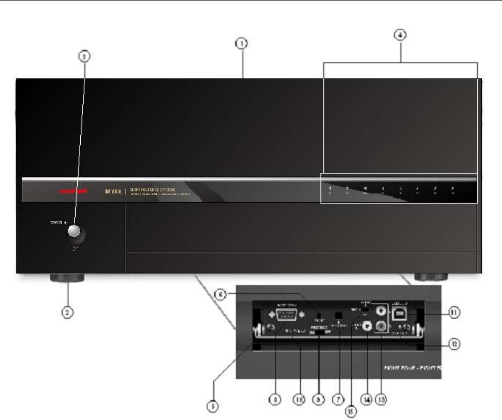
Figure 2 – The Model MX88 Controller/Amplifier – Front Panel Features and Functions
MX88 FRONT PANEL FEATURES AND CONNECTIONS:
1. Front Panel.
2. Chassis Feet. Set high enough to provide through-chassis cooling by natural convection.
3. Master AC Line On/Off Switch. Turns AC power On/Off to the entire unit.
4. Power and Status LED Indicators. Eight indicators, one for each Zone, provide the following status
information:
System Status (Power-Up Mode)
a) Slow Pink Blink – indicates general initialization is occurring.
b) Fast White Blink – indicates that a keypad on the associated zone is currently being initialized.
c) Fast Red Blink – indicates that the master keypad on the associated zone is not responding to
initialization.
d) Fast Pink Blink – indicates that the slave keypad on the associated zone is not responding to
initialization.
e) All Lights Off – initialization is done, system is ready for operation.
Model MX88 Page: 11
© 2010 Xantech LLC
Zone Status (Active-Operational Mode)
a) Steady White – indicates that the Zone is Active (Keypad ON), is not muted and is not within 5 dB of
MAX-V (Maximum Volume).
b) Steady Red – indicates that the Zone is Active, is not muted and is within 5 dB of MAX-V.
c) Slow White Blink – indicates that the Zone is in the Active, is muted and is not within 5 dB of MAX-V.
d) Slow Red Blink – indicates that the Zone is Active, is muted and is within 5 dB of MAX-V.
e) Fast White Blink – indicates that Zone is Active, is being Ramped Up or Down and is not within 5 dB of
MAX-V.
f) Fast Red Blink – indicates that the Zone is Active, is being Ramped Up or Down and is within 5 dB of
MAX-V.
f) Off to indicate that Zone is in Not Active (Keypad OFF).
5. Front Panel Access Door. Push gently on lower half of door to open. Allows access to programming
connections, Level Reset and Front Panel Source 8 A/V Input.
6. Level Reset. Pressing this button twice within 1 second restores all of the Factory Default Settings for all
zones. The Factory Defaults are as follows:
Mute Off
Treble and Bass Flat
Balance Centered
Z-Adjust Treble and Bass Flat
Z-Adjust Balance Centered
Z-Adjust Max-V Cleared
Z-Adjust Max-On-V Cleared
Trim Levels Cleared
IR Code Group set to A8
NOTE: The MX88 will always return to last set values (plus any unaltered factory defaults) after main power
shut down or after any power interruptions.
7. IR Learning Eye. The IR Eye on the MX88 Controller front panel allows teaching IR Codes to Dragon
Drop-IR™ via the Control Amp when connected to a PC „s com port.
8. RS232 Com Port. DB9 Connector. Used to program the MX88 Controller or perform firmware updates from
a PC, using the Xantech Universal Dragon Software.
9. PROTECT On/Off Switch. Selects between Programming Mode (OFF position) and PROTECT (ON)
position to keep program secure in memory.
10. STATUS A Led. Green Activity LED, lights during Program Download from Universal Dragon Software,
during IR Learning and for firmware updates when using the RS232 Port located on the front panel
11. USB Com Port. Used to program the MX88 Controller or perform firmware updates from a PC, using the
Xantech Universal Dragon Software.
12. STATUS B Led. Green Activity LED, lights during Program Download from Universal Dragon Software,
during IR Learning and for firmware updates when using the USB Port located on the front panel.
13. Source 8 AUDIO IN L/R. Front panel Source 8 line level audio input. Gold-plated RCA Jacks for use with
any desired A/V source component such as camcorder, video game console, or other.
14. Source 8 VIDEO IN (MX88vi only). Front panel Source 8 composite video input. Gold-plated RCA Jacks
for use with any desired A/V source component such as camcorder, video game console, or other.
15. Source 8 Front/Rear Selector Switch. Selects whether the Source 8 Audio/Video inputs will come from
the Front (F) or Rear (R) panel jacks.
Page: 12 Model MX88
© 2011 Xantech Corporation
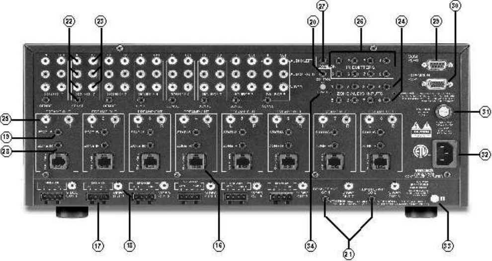
Figure 3 – The Model MX88 Controller/Amplifier – Rear Panel Connections and Functions
MX88 REAR PANEL FEATURES AND CONNECTIONS:
16. Keypad Terminals (8). Each Zone has one RJ-45 jack for Keypad Interface. Each connector interfaces the
following: Power (Enough for 1 Primary & up to 4 Secondary Keypads per Zone), RS-485 Data I/O, and IR
Input.
17. Speaker Terminals (8). Plug-in 4-terminal screw type connectors for zones 1 thru 6, permit speaker wire
sizes up to 12AWG.
18. Composite Video Output (8). RCA type connector sends zone selected, source video to the composite
video input on a zone TV or modulator (applies to MX88v(i) only).
19. Status Out (8). Provides a control output of +12 VDC that turns on and off with the zone to drive voltage
sensing relay modules and AC strips.
20. Control Out (8). Mono 3.5mm Mini Phone Jack provides a Control Output that goes high (+12 volts) when
any Zone is first turned ON and goes low (0 volts) when the last Zone is turned OFF. [Tip=+VDC;
Shield=GND]
21. Remote Amp Control Out (CO1 & CO2). Stereo 3.5mm Mini Phone Jack connects to CONTROL IN jack
of Remote Amp PA435X or PA4100X. Provides STANDBY and MUTE Control of remote Amp from Zone 7
(CO1) and Zone 8 (CO2). [Tip = STANDBY Logic; Ring = MUTE Logic; Shield = GND]
22. Source Component Input Connections (8)
a) Source Audio Inputs. Gold-plated RCA Jacks for Stereo/Dolby Pro line level audio input from source
components.
b) Source Video Inputs. Gold-plated RCA Jacks for composite video input from source components
(Applies to MX88 only).
c) Sense Inputs. 3.5mm Stereo Mini Phone Jacks for use with the CSM1 MX88 Current Sense Module.
Model MX88 Page: 13
© 2010 Xantech LLC
23. Source Loop-Thru Connections (8).
a) Audio Loop-Thru. Parallel Connection to Audio Inputs for connecting Audio Source to another MRC-
88 in Expanded Mode or to other local devices. This is not an active output.
b) Video Loop-Thru (MX88vi only). Buffered Video Connection for connecting Input Video Source to
another MX88vi in Expanded Mode or to other local devices. NOTE: Since this is a Buffered video
connection, this loop-thru is not active when POWER is removed from the MX88vi.
24. Zone Audio Inputs (8). 3.5mm stereo mini phone jack for zone specific stereo audio source Inputs. Zone
Audio Inputs override rear panel, Source 1 connection. Allows each of the 8 zones to have a dedicated
source output by selecting Source 1 on keypad.
25. Zone Audio Pre-Amp Out (8). Gold-plated RCA jacks for connecting Zone Audio Output to an external
amplifier. For use with applications where either more power is required for zone or passing to a Dolby
Surround compatible receiver for theater quality audio in zone.
26. IR Emitters (1-8). 3.5mm mono mini phone jacks. These mini jacks are for the connection of IR emitters to
control individually the eight source components. These jacks are “steerable” with Universal Dragon
Software for IR Routing and Priority Lockout. IR received from a Zone will be routed to the emitter port
corresponding to that zone‟s active source selection. Can also be configured as 8 common emitter ports
using Universal Dragon.
27. IR Emitter (Common). 3.5mm mono mini phone jacks. Single Common IR output that can be used to
control devices such as Multi Zone Audio Server, motorized drapery systems, TV lifts and lighting systems
or any other IR controlled component. IR Received from any zone keypad will be output the Common
emitter port regardless of source selection.
28. Zone IR Out (8). 3.5mm mono mini phone jacks. IR received from a zone will always be passed to the
corresponding Zone IR output. This can be used to control Zone Specific components not located in the
zone.
29 and 30. Com Ports 1 and 2. DB15 (DB15-to-DB9 adaptors included) Bi-Directional RS232 Ports allow full
control of all Internal Amplifier Commands of the MX88 Controller and the ability to trigger programmed IR
Macros for control of devices connected to the Controllers emitter ports, from an external PC. The Com
Ports can also be used to send ASCII/Hex commands out to control an external RS232 device directly from
the MX88 Keypad and/or handheld remote, and receive status information and metadata from the device.
Port 1 is also used for system expansion, where the port 1‟s of two MX88‟s allow them to be connected
together, via included Expansion Cable, to provide an 8 Source/16 Zone system with full control between
units.
31. User Replaceable Fuse. 10 AMP L 250 VAC.
32. AC Power Input. Standard IEC 3-Conductor AC line cord to be used with a 3-conductor power line cord.
33. Grounding Screw. “Knurled Screw” provides a means for chassis connection to earth ground or to other
Audio/Video products to aid in the reduction of system noise.
34. Power On/Off LED. This LED will be lit in white when the MX88 is on.
35. Ethernet Port (MX88vi and MX88ai only): Connects to a Local Area Network, and allows the control of all
the zones of a MX88vi or ai from almost any wired or wireless IP-enabled device with web browsing
capabilities, such as the Apple® iPad®, Windows® and Android™ tablets, and PCs. It also allows for some
limited 2-way external device interface, subject to expansion in the future. This port is also used for setting
configuring the IP address and performing firmware updates for the MX88vi/MX88ai‟s built-in web server,
using the Xantech MRIP Installer Software.
Page: 14 Model MX88
© 2011 Xantech Corporation
Section 2: Installation & Connections
INSTALLATION
Installing an MX88 system involves completely planning the system from hardware, installation, and
programming standpoint, before the actual installation begins.
We strongly recommend, before physical installation begins, that all the actual components to be used as part
of the MX88 system are physically connected and tested individually first, and then tested again as a system
with a fully programmed and configured MX88. This added effort can become a valuable investment in quick
and effective troubleshooting in case any issues are encountered after installation.
We also recommend that all installed wiring is checked thoroughly and systematically for continuity and
integrity, using proper test equipment designed for the specific type of wiring.
OPERATION: OUT-OF-THE-BOX PRE-TEST
The MX88 is shipped to operate basic functions „Out-Of-The-Box‟ without any programming. Simply by plugging
in keypads via standard CAT-5 RJ45 terminated patch cable and powering the controller „on‟, you can control
Source Selection, Volume Up/Down and speaker Mute capabilities.
Completing the Out-Of-The-Box Pre-Test will verify that all sources and zone components are working properly
to select and distribute audio and video prior to programming via QuickConfig or with the Universal Dragon.
This will ensure that the unit is indeed functioning correctly „prior‟ to fixed installation and allow proper
troubleshooting procedures if a problem is encountered. Instructions regarding full programming for specific
components and features will follow.
Notes:
- For Expanded, 16-zone configuration, test both units individually as outlined below.
- For simplicity of test set-up, only one Source Component, one pair of speakers, and one TV/Video
Monitor will be necessary.
For the pre-test the MX88, you will need the following:
8-RJ45 Terminated CAT5 cables. (Pre test cables prior to use – See Caution below)
1-Audio/Video Source Component (i.e. BluRay or DVD player, etc.) [Will be used to test ALL Source
Inputs]
1 Audio/Video RCA Harness (Capable of Audio Left/Right and Video)
1-Pair of speakers with Speaker Cable properly terminated into the included 4 conductor WECO-style plug
[Will be used to test Speaker outputs]
1-TV or Video Monitor [Will be used to test ALL Video Outputs – MX88 only]
8-283D Blink Emitter
All 8 MX88-compatible keypads or touch-screens
AC Cord
1. Connect MX88 Controller/Amplifier as shown in Figure 6 to:
a) All MX88 keypads via CAT5 Cables
c) Audio/Video Source to SOURCE 1 Audio Left/Right and Video Input terminals
d) TV or Monitor to Video Out 1 (MX88 Only).
e) Speakers to Speaker Output #1
f) All 8 IR emitters to IR Emitter Ports 1 thru 8 (Figure 3, item 26)
g) AC Power for MX88 Controller and Audio/Video Source Component

Model MX88 Page: 15
© 2010 Xantech LLC
2. Press “Power On” button on the front of the MX88 Controller/Amplifier (wait for front panel power LED to
turn on, and the 8 zone LED‟s to stop flashing – usually less than 2 minutes).
3. Power ON the Zone 1 TV/monitor and select the appropriate input (on the TV or monitor).
4. Power ON the Source Component and press play.
5. Place the emitter from IR Emitter Port 1 near the front of the Source Components IR Sensor window.
6. Press “POWER” on the Zone 1 Keypad.
7. Select “SRC1” on the Zone 1 MX88 Keypad.
a) If Source 1 is an Audio/Video component, the video content of the source connected to the Source 1
inputs should be seen on the zone 1 TV/monitor.
b) Press “VOL+” on the Zone 1 Keypad. The Volume bar should move on the Keypad and the audio
content of the source connected to the Source 1 inputs should be should be heard through the Zone 1
speakers.
c) Press “MUTE” on the Zone 1 Keypad. The Zone 1 speakers will mute. Press MUTE again and the
speakers will un-mute. (Pressing VOL+ or VOL- will also un-mute the speakers).
d) Use the source 1 original equipment remote and verify that all source functions operate when aiming
the remote at the Zone 1 Keypad IR sensor.
e) Press “POWER” on the Zone 1 Keypad and verify ALL Status LED‟s on the Controller Front Panel are
OFF.
8. Move the Audio/Video Source component to SOURCE 2 Audio Left/Right and Video Input terminals;
Speakers to Speaker Output #2 and the TV/Video Monitor to Video Out #2.
9. Repeat Steps 5 thru 8 for source/Zone 2 thru 8
Caution: Power voltage for the keypad is transmitted along the CAT5 cable! Incorrect wiring on this cable
can destroy the keypad or touch-panel. Please test the cable connections using a proper CAT5
cable tester or using a multimeter to check Pin to Pin continuity and for possible shorts. Using either
method, it is advisable to measure pins 3 and 6 to verify proper voltage with a multimeter. A 12Vdc
measurement should be read when the positive probe is on pin 6 and the negative probe is on pin 3.
See Figure 10.
MX88 CONTROLLER/AMPLIFIER PHYSICAL LOCATION
1. The MX88 is convection cooled. It depends on the natural free flow of air up through its slot perforations in
and over the internal heat dissipating fins for adequate cooling.
2. Should adequate cooling be desired, external fans and other means of air ventilation can be used.
3. Once installed, your MX88 will have large bundles of wire and cable to accommodate audio, video and
speaker connections. Be sure to allow enough room for the leads and dress them in such a manner so as
not to block airflow.
4. The MX88 is designed for mounting on flat horizontal surfaces.
5. Do not remove chassis feet. They are necessary to provide proper ventilation.

Page: 16 Model MX88
© 2011 Xantech Corporation
CONNECTING THE MX88 CONTROLLER/AMPLIFIER
IMPORTANT!
a. The MX88 comes with detachable IEC-type AC cords. The mains plug end of the AC cord or its
MX88 back-panel attached AC inlet are the disconnect device from mains, and shall remain readily
accessible by the end-user.
b. When making connections to the MX88 Controller be sure the power cord is unplugged. Proceed as
follows, referring to Figure 3 and Figure 6 or 7 for a typical MX88 system layout and interconnections.
SOURCE RELATED CONNECTIONS
The following relates to all source related connections to the MX88 Controller Unit (A/V In/Out, IR Control,
Sense Inputs etc.)
SOURCE COMPONENT CONNECTIONS
Audio Connections
8-zone system:
Using good quality RCA-type patch cables connect the LEFT and RIGHT OUTPUT jacks of the source
component (DVD, CD, Satellite receiver, etc.) to the appropriate source AUDIO LEFT and AUDIO RIGHT
INPUT jacks on the MX88 - Figure 3 item 22. Do this for each source component.
Expanded, 16-zone system:
Using good quality RCA-type patch cables connect the source AUDIO LEFT and AUDIO RIGHT OUTPUT
Jacks of the „Primary Controller‟ - Figure 3 item 23. to the corresponding source AUDIO LEFT and AUDIO
RIGHT INPUT jacks on the „Secondary Controller‟ - Figure 3 item 22.
Video Connections (MX88vi Only)
8-zone system:
Using good quality RCA-type video patch cables connect the VIDEO OUTPUT jacks of the source
component to the VIDEO INPUT jacks on the MX88 - Figure 3 item 22. Do this for each source
Component.
Expanded, 16-zone system:
Using good quality RCA-type patch cables connect the source VIDEO OUTPUT jacks of the „Primary
controller‟ [Figure 3 item 23] to the corresponding source VIDEO INPUT jacks on the Secondary Controller
- Figure 3 item 22.
ZONE AUDIO INPUTS
NOTE: The Zone Audio Input feature is enabled via Universal Dragon software only and cannot be done via
QuickConfig.
Use a “3.5mm stereo mini jack to stereo RCA plug adapter” to connect Zone Specific audio sources (i.e. an
audio source located in a zone) to the appropriate Zone Audio Input - Figure 3 item 24. The 3.5mm stereo
jack is wired as follows: Tip = Right Audio Input; Ring = Left Audio Input; Sleeve = GND. When enabled, the
Zone Audio Input will override the Source 1 Input connected at the Audio Left/Right RCA Input terminals -
Figure 3 item 22. The Zone Input feature is audio-only regardless of the model version of MX88.
Expanded, 16-zone system:
For Zones 1-8, connect to the Primary Controller‟s Zone Audio Inputs. For Zones 9-16 connect to the
Secondary Controller‟s Zone Audio Input.

Model MX88 Page: 17
© 2010 Xantech LLC
IR CONTROL CONNECTIONS
8-zone system:
Plug the supplied 283D IR emitters into the appropriate IR Emitter jacks - Figure 3-(26). Take care to match
the source audio and video connection number on the MX88 to the IR Emitter jack number. This will ensure
that the IR control signal will be routed to the correct source component. Find the IR sensor window on the
source component and attach the emitter to the components sensor window after removing the protective
paper cover on the flat side of the emitter head. A Common IR jack is also provided for connection to other
auxiliary devices that are not source specific - Figure 3 item 27.
Expanded, 16-zone system:
Connect the emitters to the Primary Controller‟s IR Emitter jacks - Figure 3 item 26 as noted above.
Note: The appropriate source IR Emitter of the Secondary Controller will also flash regardless of what
zones keypad issues the command but it is recommended to use the emitter jacks of the Primary unit.
SENSE INPUT CONNECTIONS
8-zone system:
The sense input connection will typically be used to sense the power state of a source component using
any of the Xantech Sense Modules (sold separately). Plug the 3.5mm mini plug from the Xantech sensor
into the appropriate sense jack – Figure 3 item 22. Take care to match the source audio and video
connection number on the MX88 to the appropriate sense jack number. Please refer to instructions included
with the specific sensor that you are using for set up and any necessary adjustments.
Expanded, 16-zone system:
Connect the Xantech sensors as described above to the Primary Controller. Sense inputs on the Secondary
Controller are inactive and are not to be used.
BI-DIRECTIONAL CONTROL PORTS
RS232 Ports 1 and 2:
These DB15 ports, when used with the included DB15-to-DB9 adaptor cables, can be used for controlling
and receiving status information/metadata from external devices and components, or for allowing external
devices to control the MX88. Port 1 can also be used to link one MX88 to another, using the supplied DB15-
to-DB15 expansion cable, creating a 8 source/16-zone “Expanded” system.
Ethernet jack (MX88vi and MX88ai only):
Used for connection to a Local Area Network, and allowing control of all the zones of MX88vi or ai from
almost any wired or wireless IP-enabled device with web browsing capabilities, such as the Apple® iPad®,
Windows® and Android™ tablets, and PCs. It also allows for some limited 2-way external device control,
subject to expansion in the future. The MX88 comes with DHCP enabled so that it can be accessed through
a dynamically enabled network. Its address should be fixed to a fixed IP address that is supported by your
Local Area Network, using the “MRIP Installer” program that can be downloaded at
http://www.xantech.com/Audio/AVDistribution/AVDistribution/MX88/ . Please see the “MX88 MRIP Quick
Start” document at the same URL for details.
ZONE RELATED WIRING CONNECTIONS
In typical applications, each zone will have at least one MX88 keypad or touch-panel, and a pair of
speakers. In zones with both audio and video (MX88vi), at least one video monitor or television will also be
used. In order to make these connections, the minimum requirement is home runs of one CAT5 cable for
each zone‟s keypad(s), two pairs of 12-18AWG wire for each pair of speakers, and one coaxial cable for a
TV or monitor (MX88vi) from each zone to the MX88 Controller/Amplifier location.
SPEAKER CONNECTIONS
1. Using good quality speaker wire, connect the individual speaker leads to the 4-terminal "SPEAKER"
connectors on the MX88 as shown in Figure 3 item 22.

Page: 18 Model MX88
© 2011 Xantech Corporation
2. The MX88 Speaker Terminals (amplifier outputs) are 4-Ohm compatible. Make sure the combined
impedance presented to the speaker terminals by the speakers (or any combination of speakers) is 4-
Ohms minimum.
3. Be sure to observe correct polarity by connecting the "+" and "–" terminal from each channel on the
MX88 to the corresponding "+" and "–" terminals on each speaker. This will ensure proper speaker
polarity and have the left and right speakers operate “in phase”. These connectors are removable, so
you may unplug them for ease of speaker wire lead assembly.
4. As a rule of thumb, use 18 gauge speaker wire for speaker runs up to 30' (9m), 16 gauge up to 70'
(21m), and 14 gauge up to 150' (39m). The 4-terminal connectors accept wire sizes up to 12-gauge.
5. Strip the insulation back about 1/4" (6mm) and twist the strands on each lead to prevent fraying.
6. Speaker Polarity: To obtain stable imaging and full bass response, it is imperative that stereo speakers
be connected "in phase" with each other. You can verify this as follows:
a) If the "+" (positive) and "–" (negative) terminals on your speakers are correctly marked, and visible,
and you have wired the system with the positive connector on the rear of the MX88
Controller/Amplifier connected to the positive connector on the speaker and the negative connector
on the rear of the MX88 Controller/Amplifier connected to the negative connector on the speaker,
then the system will be "in phase". No further action is required. Most manufacturers identify the
positive terminal with a red binding post, a "+" sign, or a red dot.
b) If you are unsure of the markings, you can verify that your speakers are in phase (but not the
absolute polarity of each speaker). Using a mono sound source, such as AM radio, alternately
reverse the leads to one of the speakers. Pick the connection that delivers a solid center image
between the speakers as well as best bass response.
CAUTION: After lead ends are inserted and the screws tightened down, be sure there are no free
strands that could cause shorting!
MX88 KEYPAD CAT5 CABLE CONNECTIONS AT THE MX88 CONTROLLER/AMPLIFIER
NOTE: While we use the term CAT5 throughout this manual, CAT5/5e/6/7 may be used to connect the MX88 to
Xantech keypads and touch-panels. Bear in mind that cable quality may reduce maximum lengths quoted
throughout this manual or in the keypad or touch-panel manuals.
The MX88 utilizes „Pin-to-Pin‟ CAT5 cabling for its wired zone controllers (MX-compatible keypad or touch-
panel) that can be purchased pre-fabricated at fixed lengths or self-assembled to custom lengths. The color-
coded wiring standard is EIA/TIA 568B as shown in Figure 4. The plastic connector on the end of the CAT5
wire is “registered jack” RJ45.
1. See Figure 4 for proper termination of the CAT5 cables to the RJ45 connectors.
2. Connect the zone keypad to the appropriate zone Keypad connector on the rear of the MX88
Controller/Amplifier – Figure 3 item 16.
Caution: Operating voltage for the keypad is transmitted along this cable! Incorrect wiring on this cable can
destroy the keypad or the touchpanel! Be sure to test cable for proper connections before making connections.
Model MX88 Page: 19
© 2010 Xantech LLC
Figure 4 - CAT5 Pin Assignments (per EIA/TIA 568B) Pinned 1:1
VIDEO CONNECTIONS (MX88VI ONLY)
1. When running composite video to a TV or monitor, use RG6 coaxial or RG59 quad-shield cable with
RCA-type phono plugs on each end. This connection can be run up to 150 feet, as this is a buffered
video output from the MX88 Controller/Amplifier.
2. Connect the zone video cable to the appropriate zone video jack on the rear of the MX88vi Controller/
Amplifier – Figure 3 item 18.
STATUS CONNECTIONS AND COMMON CONTROL OUT
Status
Each zone has a Status Output –Figure 3 item 19, that provides a control output of +12 VDC, 50mA that
turns ON and OFF with the zone ON/OFF condition. ON = +12VDC, OFF = 0VDC. Using a 3.5mm mono
mini phone connector, this control can be used to close a relay, such as a Xantech CC12, to raise a TV lift
or drop a projection screen automatically when a zone is turned ON. Connect one end of the 3.5mm Mono
Mini jack to the appropriate zone Status connector on the rear of the MX88 Controller/Amplifier and the
other end to the device to control. Tip=Control Voltage; Sleeve=GND
Control Out
A single Common Control Output is provided on the rear of the MX88 Controller/Amplifier –Figure 3 item
20. When the Common Control Output is High (+12VDC, 50mA max.), this indicates that „at least‟ one zone
is powered ON. When the Common Control Output is Low (0VDC), this indicates that „all‟ zones are OFF.
Using a 3.5mm mono mini phone connector, this control can be used to close relays (such as Xantech
CC12) or turn on an AC outlet (such as Xantech AC1 or AC2) for activity common to the system. Connect
one end of the 3.5mm Mono Mini jack and the other end to the device to control. Tip=Control Voltage;
Sleeve=GND
Expanded, 16-zone system:
When at least one zone on either the PRIMARY or SECONDARY controller is turned ON, the Control Out
on the PRIMARY Controller is High (+12VDC, 50mA max.). The Control Out on the Secondary Controller is
inactive in Expanded mode.

Page: 20 Model MX88
© 2011 Xantech Corporation
PREAMP OUT
Each zone has a Preamp Out to send „zone selected‟ audio to an outboard power amplifier such as the
Xantech PA4100x. This may be needed for powering a sub-zone, or for use in zones that require more than
50W a channel, or for sending audio to another amplifier with Dolby™ surround decoding for „theater
quality‟ audio in that zone.
Using good quality RCA-type patch cables, connect the Preamp Out, Left (L) and Right (R) connectors –
Figure 3 item 25, to the desired external amplifiers Audio Left and Right Input connectors.
CO1 AND CO2 (ZONES 7 & 8)
Zones 7 and 8 have a Remote Mute/Standby output for interfacing and controlling an external power
amplifier, such as the higher powered PA4100x. The control is provided via a Stereo Mini Jack with the “tip”
of the mini-phone connector controlling “standby” logic (Power On = +12VDC, Power Off = 0VDC) and the
“ring” controlling “mute” logic (Mute = +12VDC, Un-Mute = 0VDC).
Using a 3.5mm stereo mini Jack to 3.5mm stereo mini Jack cable, plug one end into the CO1 (or CO2)
output jack on the rear of the MX88 Controller/Amplifier – Figure 3 item 21 and the other end into the
corresponding jack labeled CO1 (or CO2) on the Xantech power amplifier.
NOTE: If using a Xantech PA4100X amplifier, be sure to set the Control In (CI) switch to ON located on the
rear panel of the amp.
ZONE IR
Using Xantech emitters (282D, 283D,284D, 286D, etc.), plug the 3.5mm mono mini jack into the
appropriate zones Zone IR connector – Figure 3 item 28. Affix the emitter side to the desired zone related
component you wish to control. If more than one device needs to be controlled, use a mono mini to
stripped-ends wire (p/n 6015900) wired to a Xantech 791-44 Amplified Connecting block. Any IR from the
zone (generated by the touch-panel, received at the keypad or touch-panel and passed through, or routed
from another zone (set up via Universal Dragon only) will be outputted from this emitter port.
AC POWER CONNECTIONS
Use one of the supplied AC power cords specific to your region or country, insert it into the AC inlet on the
back panel of the MX88, and plug into a power source capable of delivering the rated current and power
stated on the back panel of the MX88.
CONNECTIONS AT THE ZONE LOCATION
KEYPAD CONNECTIONS AND JUMPER SETTINGS
Single Keypad CAT5 Connections
1. Refer to Figure 4 for proper termination at the zone-end of the CAT5 cable.
2. Set Keypad Address, using specific instructions provided in the manual for that specific keypad.
2. Connect the CAT5 cable from the MX88 Controller/Amplifier into the RJ45 jack marked “Controller” on
the rear of the MX88 keypad.
Caution: Power voltage for the keypad is transmitted along this cable! Incorrect wiring on this cable can
destroy the keypad or touch-panel! Be sure to test cable for proper connections before making connections.
Multiple Keypad Connections
1. For a second keypad in the same zone, terminate the CAT5 cable in the same way as shown in Figure
4.
2. Connect the CAT5 coming from the MX88 Controller to the “CONTROLLER” jack on the Primary
Keypad. Plug a CAT5 cable into the “EXPANSION” jack on the Primary Keypad and connect it to the
Model MX88 Page: 21
© 2010 Xantech LLC
“CONTROLLER” jack on the Secondary Keypad. Repeat for all keypads in zone (up to a total of 4
Keypads). Each of the 4 keypads or touch-panels within a zone must have a unique address that is not
shared by the other three keypads.
Zone Termination
The LAST keypad connected in the zone (Keypad with no other keypad plugged into its EXPANSION
port) must have the Zone Termination Jumper installed. Please see the keypad or touch-panel‟s
manual for specifics.
Sensor Enable
To disable the keypad or touch-panel‟s on-board IR Receiver, remove the Sensor Enable jumper on
the rear of the keypad. Please see the keypad or touch-panel‟s manual for specifics.
External IR Terminal Block
To conveniently add other Xantech IR Receivers or IR keypads (such as SmartPad or WaterPad) in
conjunction with the MX88 Keypads, you may wire 18AWG-24AWG 4-conductor wire, directly to the
terminal block on the rear of the Keypad. Please see the keypad or touch-panel manual for specifics. A
4-conductor connector is provided to safely wire the +12V, STATUS, IR IN and GND to the rear of a
compatible keypad or touch-panel. This might be useful when adding an external IR Receiver or adding
a sub-zone keypad either outdoors or in a bathroom (such as the WaterPad).
Note: The 12VDC output terminal is rated at 100mA and can power up to one SmartPad/WaterPad or
up to 4 IR Receivers. Any more then this will require the use of an external power supply. Do not wire
the external power supply to the MX88 keypad. Wire directly to the units to be powered.
The STATUS line is an output and is active High (+12VDC) when the MX88 Keypad is powered on and
is Low (0VDC) when the Keypad is off. Use this to provide Bank Tracking LED on the SmartPad,
WaterPad or another compatible device.
In Zone IR
To wire local emitters in-the-zone (emitters used to control components in the same general area as the
keypad), wire the IR OUT and GND terminals on the rear of the keypad or touch-panel to the IR (white
stripe) and GND of the emitter cable. To control numerous components in the same area, wire these
terminals to an amplified connecting block (such as Xantech 791-44) using 18-20AWG 2-conductor
cable.
ZONE EXPANSION (CONNECTING TWO MX88 CONTROLLERS)
For systems greater than 8 Zones, two MX88 Controller/Amplifiers can be linked together for systems up to 16
Zones.
LINKING TWO MX88 CONTROLLER/AMPLIFIER UNITS
To connect two systems, simply connect the supplied DB15 Expansion Cable to Port 1 on the rear of one unit to
the Port 2 on the other – Figure 3 item 30. Either and both of the Port 2‟s can be used for source/device
control, with our without RS2321x8 router.
CONNECTING SOURCE COMPONENTS
When connecting two units together, designate one unit as the PRIMARY Unit (Zones 1-8) and the other unit as
the SECONDARY Unit (Zones 9-16). All source components should be connected directly to the PRIMARY
Units Source A/V Inputs – Figure 3 item 22. Use the PRIMARY Unit‟s Audio and Video Loop-Thru connectors
– Figure 3 item 23 to feed the source component inputs of the SECONDARY Unit – Figure 3 item 22.
All of the source components emitters should be connected to the PRIMARY Unit‟s IR Emitter Output Ports –
Figure 3 item 26. This rule applies to the Sense Inputs also.
Page: 22 Model MX88
© 2011 Xantech Corporation
CONNECTING KEYPADS OR TOUCH-PANELS:
- While we use the term CAT5 throughout this manual, CAT5/5e/6/7 may be used to connect the MX88
to Xantech keypads and touch-panels. Bear in mind that cable quality may reduce maximum lengths
quoted throughout this manual or in the keypad or touch-panel manuals.
- The maximum cable length for CAT5 connections to a single keypad and/or multiple keypads varies
depending on the keypad being used. In certain applications, external power supplies and/or the
MRC44CB1 connecting block may be needed.
- Most Xantech touch-panels require an external power supply. In such cases the length of CAT5 will not
be limited due to power requirements of the touch-panel, but by the maximum length allowed by the
MX88 keypad interface bus. When using self-powered zone controllers only in a zone, the maximum
CAT5 length from MX88 to the last controller should be 500ft or less.
- If any keypad in the zone is using an external IR receiver, or if an outdoor keypad (such as WaterPad)
or an IR-onloy keypad (such as a SmartPad) is necessary in a sub-zone, the 4-pin EXTERNAL IR
SENSOR CONNECTING BLOCK on the back of Xantech keypads and touch-panels can be used to
power this IR device. The Maximum cable run to the external IR receiver/keypad in each of the above
cases can be up to 125 feet from the keypad depending upon type and gauge of wire used.
- MRC88KP and MRC88DJKP keypads are older, legacy products that will work with the MX88, but
cannot be mixed with MRKP1/MRKP1E/MRKP2/MRKP2E or the Xantech touchpanels within the same
zone, due to using a different communications protocol.
- If no MX88-compatible wired keypads or touch-panels are used in a particular zone, IR Receivers
and/or IR based Keypads may be used as shown in Figure 6 below, using the MRC44CB1 Connecting
Block. This set up works for:
1. Zones with IR Receiver ONLY
2. Zones where a WaterPad, SmartPad, and/or IR Receiver is used
FIGURE 5
Using a CAT5 wire, connect one end into the desired Zone output of the MX88 controller and connect the
other end to the RJ45 connector labeled CONTROLLER on the MRC44CB1 connecting block. IR Receivers
terminated with a Stereo Mini Jack can be directly connected to the MRC44CB1 connector labeled IR IN.
For all others IR Receivers with bare wire or the IR keypads, use 24AWG or larger cable and connect using
the +12V, GND, and SIG screw terminals. A separate power supply is required for configurations in which
the current load will approach 100mA. In fact, we recommend that an AC Adaptor/Power Supply is always
used whenever possible. Consult the MRC44CB1 manual for complete instructions.
SPEAKER CONNECTIONS
SPEAKER POLARITY: TO OBTAIN STABLE IMAGING AND FULL BASS RESPONSE, IT IS IMPERATIVE
THAT STEREO SPEAKERS BE CONNECTED "IN PHASE" WITH EACH OTHER. YOU CAN VERIFY THIS
AS FOLLOWS:

Model MX88 Page: 23
© 2010 Xantech LLC
1. If the "+" (positive) and "–" (negative) terminals on your speakers are correctly marked, and visible, and you
have wired the system with the positive speaker connector on the rear of the MX88 Controller/Amplifier
connected to the positive connector on the speaker and the negative speaker connector on the rear of the
MX88 Controller/Amplifier connected to the negative connector on the speaker, then the system will be "in
phase". No further action is required. Most manufacturers identify the positive terminal with a red binding
post, a "+" sign, or a red dot.
2. If you are unsure of the markings, you can verify that the two speakers are connected in phase. Using a
mono sound source, such as AM radio, alternately reverse the leads to one of the speakers. Pick the
connection that delivers a solid center image between the speakers as well as best bass response.
CAUTION: After lead ends are inserted and the screws tightened down, be sure there are no free strands
that could cause a short!
VIDEO CONNECTIONS – MX88VI ONLY
Composite Video
The buffered, composite video output from the MX88vi Controller/Amplifier will drive a VIDEO INPUT on a
TV or monitor directly. Use RG6 coaxial or RG59 quad-shield cable with RCA-type phono plugs on each
end. This connection can be run for 100 feet.
Page: 24 Model MX88
© 2011 Xantech Corporation
SETTING-UP THE MX88 SYSTEM
8-zone system:
To better demonstrate the ease and versatility of programming the MX88, Figure 6 will be used to illustrate
setup for a typical application.
Expanded, 16-zone system:
For setup of an expanded system, see Figure 7.
Figure 6 –Typical 8-Zone MX88 System
Model MX88 Page: 25
© 2010 Xantech LLC
Figure 7 –Typical 16-Zone “Expanded” MX88 System

Page: 26 Model MX88
© 2011 Xantech Corporation
Section 3: Firmware and Programming
Always install the latest and most current available firmware for your MX88 and its web-server (MX88vi or
MX88ai only).
Firmware version for the MX88 and its web-server (called MRIP) – if so-equipped, can be accessed by tapping
your finger or clicking your mouse on the top banner of the web-interface page, or by using the Xantech
Universal Dragon programming software.
The latest MX88 firmware can be downloaded from http://www.xantech.com/Downloads/Firmware/
The latest web-server (MRIP) firmware can be downloaded from
http://www.xantech.com/Audio/AVDistribution/AVDistribution/MX88/ . You will need the “MRIP Internal
vx.xx.s.xx” and also the “Web Buffer Zipped Folder”, and will need to use the “MRIP Installer” program to load it.
Please see “MX88 MRIP Quick Start” document at the same URL for details.
As stated earlier, the MX88 can be programmed without a PC, using the Xantech QuickConfig feature. It can
also be customized using a PC and the Xantech Universal Dragon Windows® program.
To set up the MX88 using QuickConfig, please see the “QuickConfig Guide” at
http://www.xantech.com/Audio/AVDistribution/AVDistribution/MX88/
To set up the MX88 using Universal Dragon, please see the following documents at
http://www.xantech.com/Audio/AVDistribution/AVDistribution/MX88/
Universal Dragon Programming Guide (programming directions for MX88 are same as MRC88)
Universal Dragon MX88 Programming Instructions for MRKP2 MRKP2E
MRKP1 Programming with Universal Dragon
MRC88m – Auto Configuration Guide
MX88ai and MX88vi are IP-enabled and feature a built-in web-server and IP interface. To program this
interface, please see “MX88 MRIP Quick Start” at
http://www.xantech.com/Audio/AVDistribution/AVDistribution/MX88/
A system programmed using QuickConfig will allow for the following features to be utilized:
1. Basic Controller/Amplifier control including: Zone Power On/Off, Source Selection, Speaker
Volume, Speaker Mute, Speaker Balance control, EQ Treble/Bass adjustment from the keypad,
2. IR Code programming from the built in IR library and IR learning, for control of all source
components from the keypad function buttons as well as via the keypads‟ built-in IR Receiver.
3. 2-way RS232 programming of select Xantech-supported sources.
4. Source Power Management (Video or Current Sense) for each source connected.
5. Expanded, 16-zone system activation.
A system programmed using the Universal Dragon will allow for the following additional features to be utilized:
1. Icon Editor
2. RS232 Control of additional external components
3. RS232 Control of the MX88 Controller/Amplifier from external devices such as PC‟s
4. Programming of Internal Amplifier Commands
5. Static and Dynamic Linking of Zones
6. Priority Lockout Enable/Disable as well as Monitor Lockout
Model MX88 Page: 27
© 2010 Xantech LLC
7. IR Routing Enable/Disable
8. Use of Zone Audio Inputs
9. RC68+ IR Macro Generator
10. Configurable LCD backlight time-out settings (for MRC88KP and MRC88DJKP only).
All of the IR Codes (Palettes or IR Command Groups) and RS232 commands should be confirmed and tested
before completing programming.

Page: 28 Model MX88
© 2011 Xantech Corporation
PLANNING THE SYSTEM
Before attempting any programming, plan the system configuration first. This should include the following:
1. Determine the brand and type of all source components to be used.
Source 1: ________________________
IR File Name: _____________ IR Library Palette
Source 5: ________________________
IR File Name: _____________ IR Library Palette
Source 2: ________________________
IR File Name: _____________ IR Library Palette
Source 6: ________________________
IR File Name: _____________ IR Library Palette
Source 3: ________________________
IR File Name: _____________ IR Library Palette
Source 7: ________________________
IR File Name: _____________ IR Library Palette
Source 4: ________________________
IR File Name: _____________ IR Library Palette
Source 8: ________________________
IR File Name: _____________ IR Library Palette
Zone Audio Source 1: ______________
IR File Name: _____________ IR Library Palette
Zone Audio Source 5: ______________
IR File Name: _____________ IR Library Palette
Zone Audio Source 2: ______________
IR File Name: _____________ IR Library Palette
Zone Audio Source 6: ______________
IR File Name: _____________ IR Library Palette
Zone Audio Source 3: ______________
IR File Name: _____________ IR Library Palette
Zone Audio Source 7: ______________
IR File Name: _____________ IR Library Palette
Zone Audio Source 4: ______________
IR File Name: _____________ IR Library Palette
Zone Audio Source 8: ______________
IR File Name: _____________ IR Library Palette
CAUTION: See caution card (included) for the latest information regarding code compatibility before
finalizing the system as there may be some IR code incompatibilities.
2. Determine the components to be used in each zone. Some sources may not be available in all zones.
3. Perform the Out-of Box PRE TEST as outlined in Section 2.
4. Assemble the components into a working MX88 system such as that shown in Figure 6 or 7.
5. Decide whether the MX88 System will be programmed using QuickConfig or Universal Dragon
QuickConfig Universal Dragon
6. If using Universal Dragon:
Program the MX88 System using the latest version of the Universal Dragon, available at
http://www.xantech.com/Downloads/Software/
Transfer the System Project to the MX88 Controller(s)
7. Confirm all functions in all zones.
Model MX88 Page: 29
© 2010 Xantech LLC
Appendix
RS232 CONTROL
This document describes the bi-directional RS232 interface of the MX88 using the two COM PORTs on the rear
of the system (Fig. 3 item 29). This interface allows an external RS232 device to control the MX88 via a set of
ASCII text commands. It is also possible to control any IR device connected to the MX88 system as well by
triggering individual IR Commands and/or IR Macros via ASCII strings.
TYPES OF COMMANDS
There are two types of information that can be sent to the MX88 Controller: COMMANDS and QUERIES.
COMMANDS are ASCII strings used to set a specific parameter in the system (i.e. Select a Source, turn a zone
ON, start a DVD player etc…). QUERIES are requests for system status information and result in the MX88
controller sending back a reply to the string being sent (i.e. seeing what zones are on, which sources are
selected and volume settings etc….)
INTERFACING TO THE RS232 COM PORTs
The RS232 Com Ports on the rear of the MX88 Controller, when used with the included DB15-DB9 adaptors,
are wired as a „null modem‟ end, meaning the Transmit and Receive line have already been interchanged for
direct communication with a PC. What this means is when connecting to a standard PC‟s Com Port, no Null
Modem cable is necessary.
The pin out configuration for this connector is:
COM PORT (with DB15-DB9 adaptor)
PIN #
FUNCTION
1, 7, 8, & 9
NC
2
Tx
3
Rx
4
DSR
5
GND
6
DTR
Rear Com Port Connector Pin Out
ASCII STRING „INITIATING‟ AND „TERMINATING‟ CHARACTERS
The parsing of incoming data on the COM PORT can be disabled via a setting in the Universal Dragon project.
This might be necessary if the COM port is to be used to control an external device and any incoming data from
that device is to be ignored. This setting can be found with the settings for configuring the COM port.
For the MX88 system to recognize incoming ASCII command strings, the string must begin with an „!‟ and for
data queries the string must begin with a „?‟. All strings must end with a „+‟. This way it can determine the
beginning and end of the string for processing.
When a proper command is sent, an ASCII acknowledgement string of OK is returned to the issuing device. If
an unrecognizable string is received, an ASCII string of ERROR is returned to the issuing device.
Example #1: (Issuing a Command String);
To turn Zone 7 ON:
Send ASCII string: !7PR1+
MX88 Controller Reply: OK
Page: 30 Model MX88
© 2011 Xantech Corporation
Example #2: (Query Request)
To see what Source is currently selected in Zone 5:
Send ASCII string: ?5SS+
MX88 Controller Reply: ?5SS3+ indicating Source #3 is currently selected in Zone 5

Model MX88 Page: 31
© 2010 Xantech LLC
COMMANDS
Note: An explanation of items in parenthesis ( {} ) can be found below.
NAME
COMMAND
EXAMPLES/COMMENTS
Zone Power
!{z#}PR{0/1}+
To turn on Zone 2: !2PR1+
To turn off Zone1: !1PR0+
Zone Power Toggle
!{z#}PT+
All Zones Off
!AO+
Input (Source) Select
!{z#}SS{s#}+
To set Zone 1 to Source Input 5: !1SS5+
Volume
!{z#}VO{v#}+
Volume Increment
!{z#}VI+
Volume Decrement
!{z#}VD+
Mute
!{z#}MU{0/1}+
To mute Zone 3: !3MU1+
To unmute Zone 4: !4MU0+
Mute Toggle
!{z#}MT+
Treble
!{z#}TR{bt#}+
Treble Increment
!{z#}TI+
Treble Decrement
!{z#}TD+
Bass
!{z#}BS{bt#}+
Bass Increment
!{z#}BI+
Bass Decrement
!{z#}BD+
Balance
!{z#}BA{b#}+
Balance Step Left
!{z#}BL+
Balance Step Right
!{z#}BR+
Execute RS232 Macro
!{m#}MC+
Execute Keypad Button
!{z#}MK{k#}X{i#}+
Page: 32 Model MX88
© 2011 Xantech Corporation
QUERIES
Note: An explanation of items in parenthesis ( { } ) can be found below.
NAME
QUERY
RESPONSE
EXAMPLE
RESPONSE
EXPLANATION
Zone Power
?{z#}PR+
?{z#}PR{0/1}+
?7PR0+
Power in zone 7 is OFF.
Input Select
?{z#}SS+
?{z#}SS{s#}+
?5SS3+
Zone 5 currently has source
3 selected.
Volume
?{z#}VO+
?{z#}VO{v#}+
?4VO49+
Zone 4 is currently at volume
level 49.
Mute
?{z#}MU+
?{z#}MU{0/1}+
?8MU1+
Zone 8 is currently muted.
Treble
?{z#}TR+
?{z#}TR{bt#}+
?1TR7+
Zone 1 currently has a treble
value of 7 (flat)
Bass
?{z#}BS+
?{z#}BS{bt#}+
?1BS7+
Zone 1 currently has a bass
value of 7 (flat)
Balance
?{z#}BA+
?{z#}BA{t#}+
?2BA31+
Zone 2 currently has a
balance value of 31 (even)
Where: {z#} - Zone Number. Range is 1..8 (1..16 if expanded)
{s#} - Source Input Number. Range is 1..8
{0/1} – Either 0 (zero) or 1 (one). 0 – Off, 1 – On.
{v#} - Volume Setting. Range is 0..38. See VOLUME LEVEL table below.
{bt#} - Bass/Treble Setting. Range is 0..14. See BASS/TREBLE LEVEL table below.
{b#} - Balance Setting. Range is 0..63. See BALANCE LEVEL table below.
{m#} - Macro Number. Range is 0..256.
{k#} - Keypad Address. Range is 0..3.
{i#} – Keypad Button ID. Range is 3..40 See KEYPAD BUTTON ID table below.

Model MX88 Page: 33
© 2010 Xantech LLC
VOLUME LEVEL (39 Steps)
MX88 SETTING
ATTENUATION
LEVEL (in dB)
38
0
37
-1.25
36
-2.50
35
-3.75
34
-5.00
33
-6.25
32
-7.50
31
-8.75
30
-10.00
29
-11.25
28
-12.50
27
-13.75
26
-15.00
25
-16.25
24
-17.50
23
-18.75
22
-20.00
21
-21.25
20
-22.50
19
-23.75
18
-25.00
17
-27.50
16
-30.00
15
-32.50
14
-35.00
13
-37.50
12
-40.00
11
-42.50
10
-45.00
9
-47.50
8
-50.00
7
-52.50
6
-56.25
5
-60.00
4
-63.75
3
-67.50
2
-71.25
1
-75.00
0
-78.75

Page: 34 Model MX88
© 2011 Xantech Corporation
KEYPAD BUTTON ID
MX88
SETTING
Keypad Button Label
1
NOT AVAILABLE
2
NOT AVAILABLE
3
Source Select 1
4
Source Select 2
5
Source Select 3
6
Source Select 4
7
Source Select 5
8
Source Select 6
9
Source Select 7
10
Source Select 8
11
CH +
12
CH -
13
POWER
14
NOT AVAILABLE
15
MUTE
16
PAUSE
17
STOP
18
FF
19
REW
20
SELECT/PLAY
21
NOT AVAILABLE
22
NOT AVAILABLE
23
Tier 2 Source Select 1
24
Tier 2 Source Select 2
25
Tier 2 Source Select 3
26
Tier 2 Source Select 4
27
Tier 2 Source Select 5
28
Tier 2 Source Select 6
29
Tier 2 Source Select 7
30
Tier 2 Source Select 8
31
Tier 2 CH +
32
Tier 2 CH -
33
Tier 2 POWER
34
NOT AVAILABLE
35
Tier 2 MUTE
36
Tier 2 PAUSE
37
Tier 2 STOP
38
Tier 2 FF
39
Tier 2 REW
40
Tier 2 SELECT/PLAY

Model MX88 Page: 35
© 2010 Xantech LLC
BASS/TREBLE LEVEL
MX88 SETTING
LEVEL (in dB)
14
+14
13
+12
12
+10
11
+8
10
+6
9
+4
8
+2
7
0
6
-2
5
-4
4
-6
3
-8
2
-10
1
-12
0
-14

Page: 36 Model MX88
© 2011 Xantech Corporation
BALANCE LEVEL
(63 steps)
MX88 Setting
Left Speaker
Attenuation
(in dB)
Right Speaker
Attenuation (in
dB)
0
0
Mute
1
0
-37.5
2
0
-36.25
…
…
…
29
0
-2.5
30
0
-1.25
31
0
0
32
0
0
33
-1.25
0
34
-2.5
0
…
…
…
62
-37.5
0
63
Mute
0

Model MX88 Page: 37
© 2010 Xantech LLC
TROUBLESHOOTING
If you encounter problems, review each of the following items and take corrective action as described. If
problems persist, contact Xantech Technical Support.
PROBLEM
PROBABLE CAUSE AND SOLUTION
The MX88, after a successful Transfer from Universal
Dragon, will not send out any IR commands.
A corrupted or incorrectly learned IR code has been
transferred to the keypad.
a) Open all palettes that you used for the project.
Click Edit Palette, on the first palette. When
Palette Editor opens, retest each IR command to
see that they operate the controlled equipment.
b) Close the Palette Editor and click Edit Palette on
the next palette. Repeat this procedure for each
palette.
c) When you find the defective command "re-teach"
it again using the Learning IR Commands
procedure.
d) Before going further, test the relearned command
to see that it operates the controlled equipment.
e) In the Palette Editor, right click the defective
command on the right and delete it from the
associated palette.
f) Place the corrected command in the palette using
the Add >> function.
g) Close the Palette Editor and open the palette.
h) Click the button on the virtual keypad that has the
bad command and remove the command with a
right click.
i) Place the corrected command on the keypad
button by clicking it on the palette.
j) Redo the Transfer procedure.
CAUTION: Always test all commands before
transferring to the MX88!
I have made hardware connections as shown in Figure 6
or 7. However, when attempting to learn IR commands,
the "Waiting for IR from your Remote" display times out
with the "No IR Recorded" dialog box.
Your computer is not recognizing or finding the serial port
connection to the MX88.
Try the following in the order listed:
a) The default serial port selection (1) in Dragon
Drop may already be in use by another device in
your computer system (such as a mouse). Refer
to SERIAL PORT SELECTION, page 36, and
perform the procedure listed there and in the
following section VERIFYING COM PORT
COMMUNICATION.
b) Check and replace, if necessary, the connecting
cables and the DB9-to-DB25 adaptor.
c) The serial COM port settings, such as port
addressing and IRQ parameters, may not be set
correctly in Windows.

Page: 38 Model MX88
© 2011 Xantech Corporation
PROBLEM
PROBABLE CAUSE AND SOLUTION
Unit will not learn IR commands from certain brands and
models of remotes.
a) Because of the wide variety of IR coding and
timing relationships (there are no industry
standards), there are some IR commands that are
not learnable by the Dragon Drop-IR™.
Be sure to test all components first to see that
their IR command codes are learnable by Dragon
Drop-IR and are executable by the MX88 before
selecting final components for the system.
To aid you in this selection, see CAUTION card
included with these instructions for the latest
information relating to code compatibility.
NOTE: Certain IR commands that are not
normally learnable, or those that operate more
correctly when learned with special techniques at
Xantech, are available on the CD ROM that
comes with Dragon. These, and the most recent
updates to these files, are available on the
Xantech web site at www.xantech.com. Contact
Technical Support for details.
b) Components using IR carriers higher than 71 kHz
cannot be learned directly. Most are learnable,
however, when down-converted by Xantech
products such as the 291P, PMS12, 291-455,
MS455, etc. Refer to the Xantech Product
Catalog and contact Technical Support for details.
Be sure you have the Make and Model number of
the component and its remote before contacting
Technical Support.
"Record ERROR, try again" shows on screen while
learning IR commands or “No IR Recorded” message is
displayed.
Sometimes the command "takes" but does not operate
the device.
This may occur if you hold the "teaching" remote too far
away, too close, or at too great an angle to the front of
the MX88, or, IR interference is present.
Also, with some remotes, you may be holding down the
buttons for too long or too short a period of time when
"teaching" the commands.
Do the following:
a) Repeat the Learning procedures.
You may have to experiment with the distance the
remote is held away from the IR SENSOR on the
front of the MX88. For most cases it will need to
be within one inch of the Learning eye.
b) Vary the amount of time you hold down the
"teaching" remote's buttons. Most of the time only
a brief tap is necessary.
c) Be sure there are no sources of strong IR
interference near the MX88 (such as CFL lamps,
TVs, Your Computer Monitor, Neon lighting, etc.).
Shade or move the location of the MX88 as
necessary.

Model MX88 Page: 39
© 2010 Xantech LLC
PROBLEM
PROBABLE CAUSE AND SOLUTION
When Transferring the project to a MX88, the transfer
stops with a "Transfer aborted-Receiver Stopped
Responding" or a "Communications Error---" message.
The following items may have interfered with the
transfer of data. Check each one in the order listed,
then redo the transfer.
a) Click on Preferences under the FILE menu and
verify proper Com Port is selected
b) Make sure no other software is running that also
requires the Com Port
c) Conduct a “Base Unit – Who Am I” to verify proper
communication with the MX88.
d) Check the COM PORT interface cable for
continuity on each of its 9 leads. This is a Pin to
Pin, 1:1 configuration. Replace if necessary.
e) Your computer may have run out of system
resources (memory). Quit other open applications
and restart Windows with the MX88 connect to the
PC
.
After transferring commands to the MX88, it works fine ...
except at certain times the MX88 refuses to output any
commands at all.
IR noise may be on the IR bus-line coming from an IR
receiver in another room or rooms, preventing a clean
IR signal from arriving at the controlled component.
a) Temporarily disconnect each MX88 Keypad one
at a time, until you find the one causing the
interference.
b) Look for sources of IR interference near the IR
receiver(s) [such as PLASMA, CFL lamps, TVs,
Neon lighting, etc.]. Move or shade the IR
receiver(s) or take other steps as necessary.
The STATUS LED under the POWER button on the
Keypad is never illuminated GREEN or flickers
constantly.
Again. IR noise is probably the problem. Adjust the
Input Sensitivity of the IR Receiver might be to
sensitive. Back off (turn CCW) on the IR Sensitivity
Adj. on the rear of the keypad until the GRENN LED
comes on steady. If a PLASMA is nearby, you might
need to disable the Keypad IR Receiver and add a
Plasma Friendly unit to the system.

Page: 40 Model MX88
© 2011 Xantech Corporation
PROBLEM
PROBABLE CAUSE AND SOLUTION
Problems Controlling the MX88 via the RS232 port on
the rear of the system.
1. Check the cabling between the controlling unit
and the MX88.
2. Verify proper command is being sent to the
MX88. Refer to Appendix A and section on
RS232 Translator for recognized ASCII
commands.
3. Verify RS232 Port settings are set properly for
both devices (i.e. Baud Rate, Data Bits, Stop
Bit etc..)
4. Verify pin out from controlling device and the
MX88 to be sure proper handshaking between
the Tx and Rx lines exist.
NOTE: Tx and Rx lines on the MX88 are reversed
from a standard PC. This allows communication
between the MX88 and a standard PC Com Port
without a Null Modem cable.
Problems controlling an External Device via the MX88
rear Com Port
1. Check the cabling between the controlling unit
and the MX88.
2. Verify RS232 Port settings are set properly for
both devices (i.e. Baud Rate, Data Bits, Stop
Bit etc..)
3. Verify pin out from controlling device and the
MX88 to be sure proper handshaking between
the Tx and Rx lines exist.
NOTE: Tx and Rx lines on the MX88 are
reversed from a standard PC. This allows
communication between the MX88 and a
standard PC Com Port without a Null Modem
cable.
4. Verify the MX88 is sending the appropriate
commands out of the rear RS232 Port. This
can be done by connecting the rear RS232
Port directly to a PC‟s Com Port running
Hyperterminal. View the command in
Hyperterminal to see if the exact commands is
being output correctly.
5. Check the manufactures manual for the
correct ASCII/Hex commands.
NOTE: Sometimes a Carriage Return (0D
Hex) and even possibly a Line Feed (0A) is
required as terminating characters.
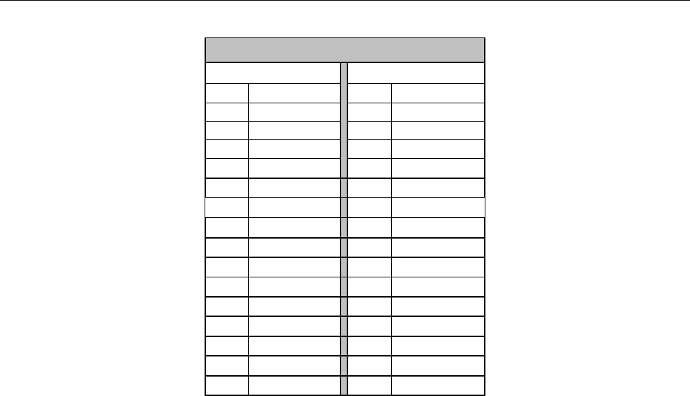
Model MX88 Page: 41
© 2010 Xantech LLC
RS232 AND EXPANSION PIN OUT INFORMATION
MX88
RS232 COM PORT*
EXPANSION PORT
PIN #
FUNCTION
PIN #
FUNCTION
1
NC
1
IR Source 1
2
Tx
2
IR Source 2
3
Rx
3
IR Source 3
4
DSR
4
IR Source 4
5
GND
5
IR Source 5
6
DTR
6
IR Source 6
7
NC
7
IR Source 7
8
NC
8
IR Source 8
9
NC
9
NC
10
IR Common
11
Tx Out
12
Common
13
Rx In
14
Sig Out
15
Sig In
* With DB9-DB16 adaptor attached

Page: 42 Model MX88
© 2011 Xantech Corporation
SPECIFICATIONS
Audio (each channel)
Min Input: .......................................................................................................... 250mV for full rated Output
Input Overload: ................................................................................................... >2.2 V RMS (@ max VC)
Input Impedance: ..................................................................................................................... > 20 k ohms
Power Output: ..................................................................................................... 50 Watts RMS @ 4 ohms
Load Impedance: ...................................................................................................................... 4 or 8 ohms
Signal to Noise:.............................................................................................................. >96dB A-Weighted
THD (VC –10dB):.................................................................................................. <0.08% at 2V input level
Frequency Response (± 1dB): ............................................................................................20 Hz to 20 kHz
Bass Control Range (@ 100Hz): .............................................................................. ±14dB (in 2 dB steps)
Treble Control Range (@ 10kHz): ............................................................................ ±14dB (in 2 dB steps)
Video (MX88vi only)
Input/Output Impedance: ............................................................................................................... 75 Ohms
Video Insertion Loss: ............................................................................................... 0 dB (50 Hz to 6 MHz)
IR Sensor
IR Modulation Frequency Bandwidth: ..............................................................................30 Hz to 100 kHz
Nominal Reception Range: ............................................................................................................ >30 feet
Nominal Reception Angle: ............................................................................................. 40 degrees off axis
General
RC68 Code Group Number: .................................................................................................................... A8
Control Output: ............................................................................................................ 12 V @ 50 mA max.
Status Output: .............................................................................................................. 12 V @ 50 mA max.
Power Requirements: ................................. 100~120V or 220~240V AC (Automatic Switching), 50/60 Hz
Gold Plated RCA type phono jacks ........................................................................... All A/V inputs/outputs
Dimensions ...................................................... 17” W x 7.625” H x 11.75” D (432mm x 194mm x 298mm)
Net Weight .......................................................................................................................... 25 lbs (20.4 kg)
Model MX88 Page: 43
© 2010 Xantech LLC
Page: 44 Model MX88
© 2011 Xantech Corporation
Xantech® and Xantech SmartPanel® are registered trademarks of Xantech LLC
Apple® and iPad® are registered trademarks of Apple Inc.
Windows® and Microsoft® are registered trademarks of Microsoft Corporation.
Android™ is a trademark of Google, Inc.
IBM® is a registered trademark of International Business Machines Corporation.
All other trademarks are the properties of their registered owners.
Xantech LLC
1969 Kellogg Ave, Carlsbad, CA 92008 USA | Xantech.com
Installation Instructions, MX88 © 2011 Xantech LLC
p/n 08905298 v0.4
This document is copyright protected. No part of this manual may be copied or reproduced in any form without prior written
consent from Xantech LLC. Xantech LLC shall not be liable for operational, technical, or editorial errors/omissions made in
this document.
