BLH3500 Manual EN
User Manual: Manual Blade mCP X BNF | HorizonHobby
Open the PDF directly: View PDF ![]() .
.
Page Count: 18
Instruction Manual
Bedienungsanleitung
Manuel d’utilisation
Manuale di Istruzioni
RTF

2
EN
WARNING: Read the ENTIRE instruction manual to become familiar with the features of the product before
operating. Failure to operate the product correctly can result in damage to the product, personal property
and cause serious injury.
This is a sophisticated hobby product. It must be operated with caution and common sense and requires some
basic mechanical ability. Failure to operate this Product in a safe and responsible manner could result in injury or
damage to the product or other property. This product is not intended for use by children without direct adult su-
pervision. Do not attempt disassembly, use with incompatible components or augment product in any way without
the approval of Horizon Hobby, Inc. This manual contains instructions for safety, operation and maintenance. It is
essential to read and follow all the instructions and warnings in the manual, prior to assembly, setup or use, in
order to operate correctly and avoid damage or serious injury.
The following terms are used throughout the product literature to indicate various levels of potential harm when
operating this product:
NOTICE: Procedures, which if not properly followed, create a possibility of physical property damage AND a little
or no possibility of injury.
CAUTION: Procedures, which if not properly followed, create the probability of physical property damage AND a
possibility of serious injury.
WARNING: Procedures, which if not properly followed, create the probability of property damage, collateral
damage, and serious injury OR create a high probability of superficial injury.
Additional Safety Precautions and Warnings
Age Recommendation: Not for children under 14 years. This is not a toy.
• Alwayskeepasafedistanceinalldirectionsaroundyourmodeltoavoidcollisionsorinjury.Thismodeliscon-
trolled by a radio signal subject to interference from many sources outside your control. Interference can cause
momentary loss of control.
• Alwaysoperateyourmodelinopenspacesawayfromfull-sizevehicles,trafcandpeople.
• Alwayscarefullyfollowthedirectionsandwarningsforthisandanyoptionalsupportequipment(chargers,
rechargeablebatterypacks,etc.).
• Alwayskeepallchemicals,smallpartsandanythingelectricaloutofthereachofchildren.
• Alwaysavoidwaterexposuretoallequipmentnotspecicallydesignedandprotectedforthispurpose.Moisture
causes damage to electronics.
• Neverplaceanyportionofthemodelinyourmouthasitcouldcauseseriousinjuryorevendeath.
• Neveroperateyourmodelwithlowtransmitterbatteries.
NOTICE
All instructions, warranties and other collateral documents are subject to change at the sole discretion of
HorizonHobby,Inc.Forup-to-dateproductliterature,visithorizonhobby.comandclickonthesupporttabforthis
product.
Meaning of Special Language
3EN
Table of Contents
To register your product online,
visit www.bladehelis.com
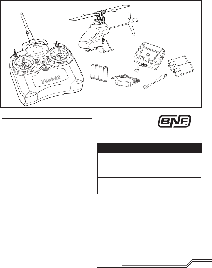
BLH3500 BLH3580
Introduction
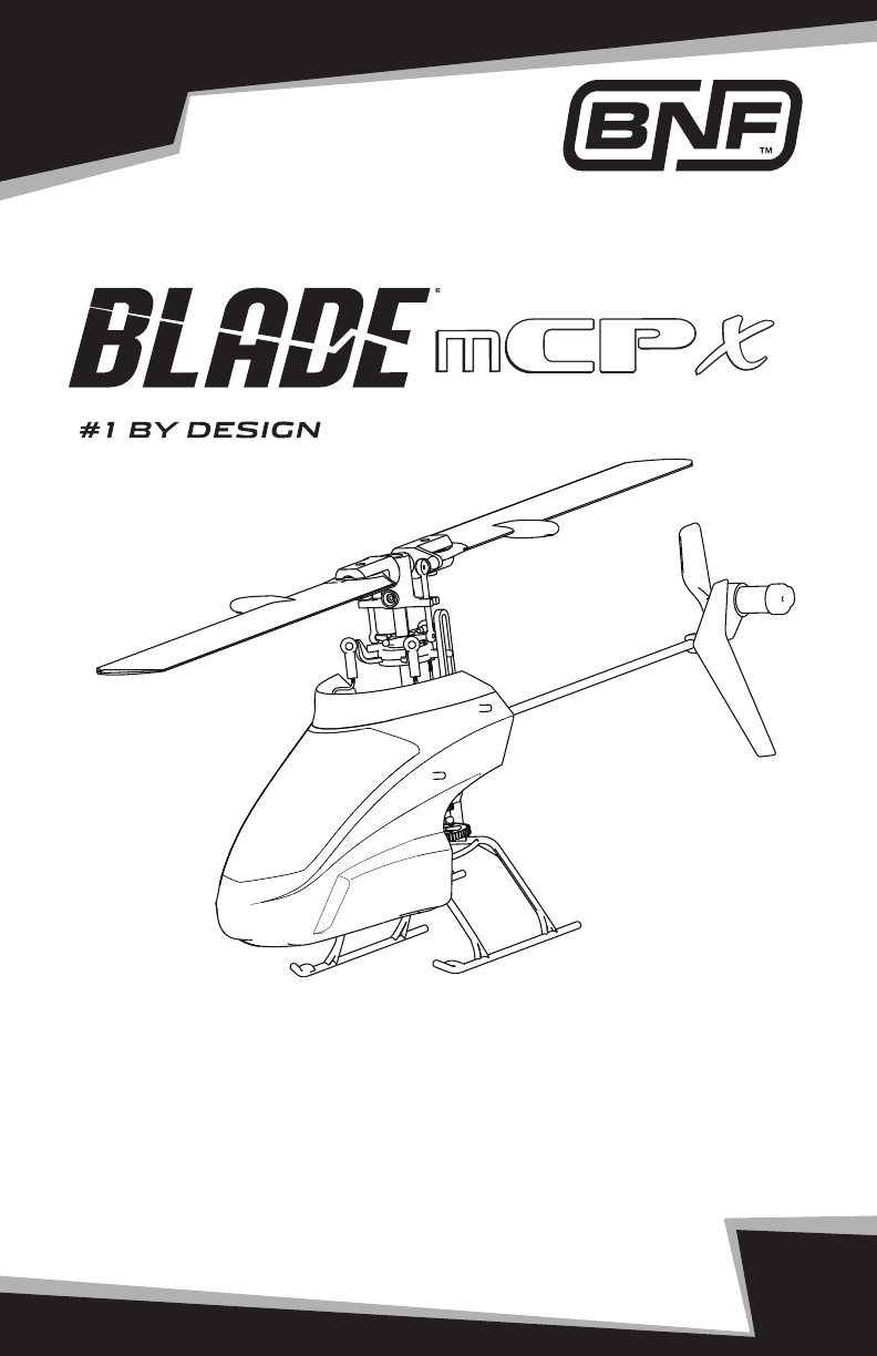
Asyouareabouttosee,theBlademCPXtrulyisanultramicroheliexperienceunlikeanyother.Itsadvancedybar-
less design reduces drag on the rotorhead and significantly boosts cyclic control response. This, combined with its
exceptionallylightweightairframe,deliversalevelofpowerandresponsivenessthateclipsesthatofanyultramicro
heliyouhaveownbefore.
Invertedight,loops,ips,rolls,funnels,hurricanes–themCPXcandoitall,indoorsorout,withpowertospare.If
you’retransitioningfromabasicCCPMorxed-pitchedheli,you’llndthemCPXisagreatwaytogetusedtoying
moreagileCCPMheliswithouthavingtoinvestalotinexpensiveequipmentorrepairs.
Beforeyoutaketherstight,though,pleasetaketimetoreadthroughthismanualandwatchtheincludedDVD.
Bothcontainimportantpre-ightinformationaswellasusefultipsonbindingyourtransmitterthatwillhelpensure
yourrstightisagreatone.
Length 9.25 in (235mm)
Height 3.65 in (93mm)
Main Rotor Diameter 9.65 in (245mm)
Tail Rotor Diameter 1.40 in (36.5mm)
Gross Weight 1.60 oz (45.5 g)
Blade mCP X Specifications
*TransmitterandAABatteriesnotincludedwithBNFVersion
Battery Warnings and Guidelines ................4
Low Voltage Cutoff (LVC) ............................4
Battery Charging .......................................5
First Flight Preparation ..............................5
Flying Checklist .........................................5
Programming Your Transmitter ...................6
Transmitter and Receiver Binding ...............7
Primary Flight Controls ..............................8
Throttle Hold .............................................9
Stunt Mode ...............................................9
Installing the Flight Battery ......................10
Flying the mCP X ....................................10
Troubleshooting Guide .............................11
Exploded View and Parts Listings .............12
Optional Parts .........................................13
Main Board Plug Configuration .................13
Warranty and Repair Policy ......................14
Customer Service Information ..................15
FCC Information ......................................16
Compliance Information
for the European Union ............................16
RTF
4
EN
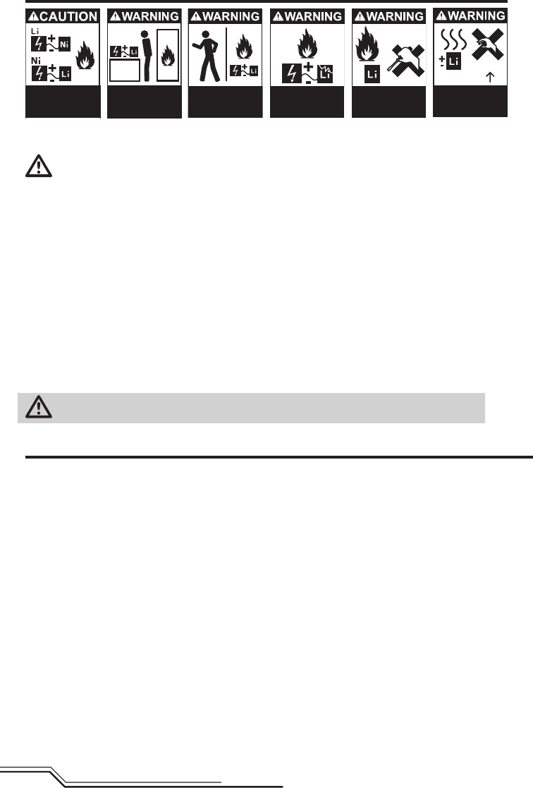
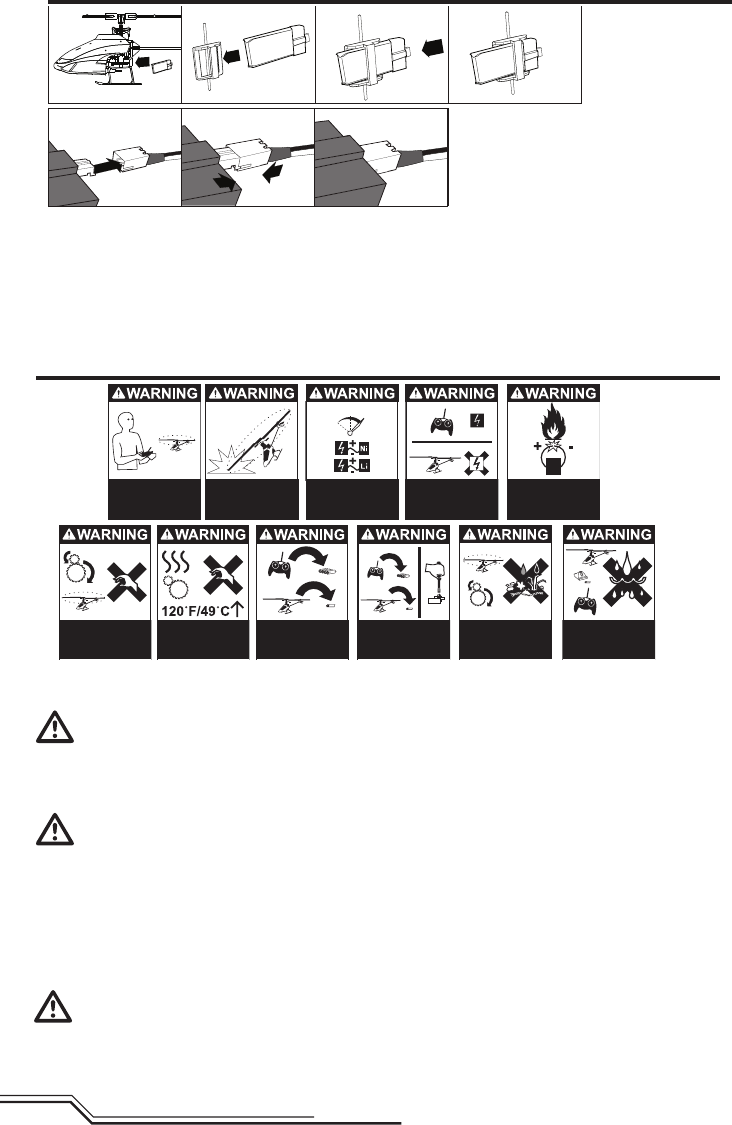
Battery Warnings and Guidelines
Always use a
charger compatible
with batteries.
Always charge
Batteries away from
flammable materials.
Never Alter
Batteries.
Never charge
damaged Batteries.
Never touch or
use hot Batteries.
120F/49C
Never leave
charging Batteries
unattended.
TheBatteryCharger(EFLC1006)includedwiththeBlademCPXhasbeendesignedtosafelychargethe
Li-Pobattery.
CAUTION:Allinstructionsandwarningsmustbefollowedexactly.MishandlingofLi-Pobatteriescanresult
in a fire, personal injury, and/or property damage.
• Byhandling,chargingorusingtheincludedLi-Pobatteryyouassumeallrisksassociatedwithlithiumbatteries.
• Ifatanytimethebatterybeginstoballoonorswell,discontinueuseimmediately.Ifchargingordischarging,
discontinue and disconnect. Continuing to use, charge or discharge a battery that is ballooning or swelling can
result in fire.
• Alwaysstorethebatteryatroomtemperatureinadryareaforbestresults.
• Alwaystransportortemporarilystorethebatteryinatemperaturerangeof40–120ºF.Donotstorebatteryor
model in a car or direct sunlight. If stored in a hot car, the battery can be damaged or even catch fire.
• NEVERUSEANi-CdORNi-MHCHARGER.Failuretochargethebatterywithacompatiblechargermaycausere
resulting in personal injury and/or property damage.
• Neverexceedtherecommendedchargerate.
• NeverdischargeLi-Pocellstobelow3Vunderload.
• Nevercoverwarninglabelswithhookandloopstrips.
WARNING:OnlyuseanE-ite6Vpowersupplywiththischarger.DONOTusea12Vpowersupplyor
property damage and injury could occur.
Low Voltage Cuto (LVC)
WhenaLi-Pobatteryisdischargedbelow3V,thebatterymaybedamagedandmaynolongeracceptacharge.ThemCP
X3-in-1controlunitprotectstheightbatteryfromover-dischargeusingLowVoltageCutoff(LVC).Beforethebattery
chargedecreasestoomuch,LVCremovespowersupplyfromthemotor.PowertothemotordecreasesandtheLEDon
the3-in-1controlunitblinks,showingsomebatterypowerisreservedforightcontrolandsafelanding.
Whenthemotorpowerdecreases,pleaselandtheaircraftimmediatelyandrechargetheightbattery.
DisconnectandremovetheLi-Pobatteryfromtheaircraftafterusetopreventtrickledischarge.Beforestorage,charge
theLi-Pobatterytofullcapacity.Duringstoragemakesurethebatterychargedoesnotgobelow3V.
NOTICE:RepeatedyingtoLVCwilldamagethebattery.
5EN
Battery Charging
Celectra™1-Cell3.7VVariableRateDCLi-PoCharger
Instructions
1.Connectpowersupplytoanappropriatepower
source.
2.Insertoutputplugfrompowersupplyintothepower
inputslotoftheVariableRateCharger.
3.Selecttheappropriatechargecurrentforyour
battery by pushing the + or -, which are the smaller
buttons to the right and left of the middle button.
(Whenchargingyour200mAhbattery,setthe
chargerto0.7amps.)
4.ConnectthechargeadaptertotheChargerlead.
Matchthereddotsonboththechargeadapterand
the Charger lead.
5.ProperlyconnectbatterytotheChargerlead.Matchthereddotsonboththebatteryandchargerconnectors.
6.PressandreleasethestartbuttonontheVariableratecharger(thelargestbuttoninthemiddle).
NOTICE: Only use the included charger.
CAUTION: NEVER attempt to power
the charger from an AC outlet without
the use of a proper AC to DC adapter/power
supply.
CAUTION: DO NOT connect charged
or discharged Li-Po batteries if the
power supply is connected to the charger
while power supply is not connected to a
power source. Doing so will discharge and
possibly damage the batteries.
LED functions under normal operation:
SINGLE SOLID LED ShowsChargeCurrent
SINGLE LED FLASHING Charging
MULTIPLE LEDs FLASHING Charge Almost Complete
LEDs SWEEPING SIDE TO SIDE Charge Complete
First Flight Preparation
Remove and inspect contents•
Beginchargingtheightbattery•
Install the four AA batteries in the transmitter•
(RTF ONLY)
Installthebladesappropriatetoyouryingstyle.•
The Fast Flight Main Rotor Blade Set is best
outdoors or for a smoother flying style. The
High-performance Main Rotor Blade Set is
best used indoors or for aggressive aerobatic
maneuvers
Installtheightbatteryinthehelicopter(onceit•
hasbeenfullycharged)
Programyourcomputertransmitter(BNFOnly)•
Test the controls•
Familiarize yourself with the controls•
Findasuitableareaforying•
Flying Checklist
Always turn the transmitter on first ❏
Plugtheightbatteryintotheleadfromthe ❏
3-in-1controlunit
Allowthe3-in-1controlunittoinitializeand ❏
arm properly
Fly the model ❏
Landthemodel ❏
Unplugtheightbatteryfromthe3-in-1 ❏
control unit
Always turn the transmitter off last ❏
6
EN
®
SETUP LIST
Model Type
HELI
Reverse
THRO-N
ELEV-N
GYRO-N
AILE-N
RUDD-N
PITC-N
Swash Type
1 Servo 90
Timer
4:00 Basic Flying
3:00 Advanced Flying
ADJUST LIST
D/R & Expo
0-AILE 70% 30%
0-ELEV 70% 30%
0-RUDD 100% INH
1-AILE 100% 30%
1-ELEV 100% 30%
1-RUDD 100% INH
Travel Adj
THRO 100%
ELEV 100%
GYRO 100%
AILE 100%
RUDD 100%
PITC 75%
Thro Curve
NORM 0% 40% 60% 80% 100%
ST-1 100% INH 80% INH% 100%
ST-2 100% 100% 100% 100% 100%
HOLD 0% 0% 0% 0% 0%
Pitc Curve
NORM 30% INH 50% INH 100%
STUNT 0% INH 50% INH 100%
HOLD 0% INH 50% INH 100%
SETUP LIST
Model Type
HELI
Reverse
THRO-N
ELEV-N
GYRO-N
AILE-N
RUDD-N
PITC-R
Swash Type
1 Servo 90
Timer
4:00 Basic Flying
3:00 Advanced Flying
ADJUST LIST
D/R & Expo
0-AILE 70% 30%
0-ELEV 70% 30%
0-RUDD 100% INH
1-AILE 100% 30%
1-ELEV 100% 30%
1-RUDD 100% INH
Travel Adj
THRO 100%
ELEV 100%
GYRO 100%
AILE 100%
RUDD 100%
PITC 75%
Thro Curve
NORM 0% 40% 60% 80% 100%
STUNT 100% 100% 100% 100% 100%
HOLD 0% 0% 0% 0% 0%
Pitc Curve
NORM 30% 40% 50% 75% 100%
STUNT 0% 25% 50% 75% 100%
HOLD 0% 25% 50% 75% 100%
SETUP LIST
Model Type
HELI
Reverse
THRO-N
ELEV-N
GYRO-N
AILE-N
RUDD-N
PITC-N
Swash Type
1 Servo Normal
Timer
4:00 Basic Flying
3:00 Advanced Flying
ADJUST LIST
D/R & Expo
0-AILE 70% 30%
0-ELEV 70% 30%
0-RUDD 100% 0%
1-AILE 100% 30%
1-ELEV 100% 30%
1-RUDD 100% 0%
2-AILE 100% 30%
2-ELEV 100% 30%
2-RUDD 100% 0%
Travel Adj
THRO 100%
AILE 100%
ELEV 100%
RUDD 100%
GEAR 100%
PITC 75%
Thro Curve
NORM 0% 40% 60% 80% 100%
ST-1 100% 90% 80% 90% 100%
ST-2 100% 100% 100% 100% 100%
HOLD 0% 0% 0% 0% 0%
Pitc Curve
NOR 30% 40% 50% 75% 100%
ST-1 0% 25% 50% 75% 100%
ST-2 0% 25% 50% 75% 100%
HOLD 0% 25% 50% 75% 100%
SETUP LIST
Model Type
HELI
Reverse
THRO-N
ELEV-N
GYRO-N
AILE-N
RUDD-N
PITC-N
Swash Type
1 Servo 90
Timer
4:00 Basic Flying
3:00 Advanced Flying
ADJUST LIST
D/R & Expo
0-AILE 70% 30%
0-ELEV 70% 30%
0-RUDD 100% INH
1-AILE 100% 30%
1-ELEV 100% 30%
1-RUDD 100% INH
Travel Adj
THRO 100%
ELEV 100%
GYRO 100%
AILE 100%
RUDD 100%
PITC 75%
Thro Curve
NORM 0% 40% 60% 80% 100%
ST-1 100% INH 80% INH% 100%
ST-2 100% 100% 100% 100% 100%
HOLD 0% 0% 0% 0% 0%
Pitc Curve
NORM 30% INH 50% INH 100%
STUNT 0% INH 50% INH 100%
HOLD 0% INH 50% INH 100%
SETUP LIST
Model Type
HELI
Reverse
THRO-N
ELEV-N
GYRO-N
AILE-N
RUDD-N
PITC-R
Swash Type
1 Servo 90
Timer
4:00 Basic Flying
3:00 Advanced Flying
ADJUST LIST
D/R & Expo
0-AILE 70% 30%
0-ELEV 70% 30%
0-RUDD 100% INH
1-AILE 100% 30%
1-ELEV 100% 30%
1-RUDD 100% INH
Travel Adj
THRO 100%
ELEV 100%
GYRO 100%
AILE 100%
RUDD 100%
PITC 75%
Thro Curve
NORM 0% 40% 60% 80% 100%
STUNT 100% 100% 100% 100% 100%
HOLD 0% 0% 0% 0% 0%
Pitc Curve
NORM 30% 40% 50% 75% 100%
STUNT 0% 25% 50% 75% 100%
HOLD 0% 25% 50% 75% 100%
SETUP LIST
Model Type
HELI
Reverse
THRO-N
ELEV-N
GYRO-N
AILE-N
RUDD-N
PITC-N
Swash Type
1 Servo Normal
Timer
4:00 Basic Flying
3:00 Advanced Flying
ADJUST LIST
D/R & Expo
0-AILE 70% 30%
0-ELEV 70% 30%
0-RUDD 100% 0%
1-AILE 100% 30%
1-ELEV 100% 30%
1-RUDD 100% 0%
2-AILE 100% 30%
2-ELEV 100% 30%
2-RUDD 100% 0%
Travel Adj
THRO 100%
AILE 100%
ELEV 100%
RUDD 100%
GEAR 100%
PITC 75%
Thro Curve
NORM 0% 40% 60% 80% 100%
ST-1 100% 90% 80% 90% 100%
ST-2 100% 100% 100% 100% 100%
HOLD 0% 0% 0% 0% 0%
Pitc Curve
NOR 30% 40% 50% 75% 100%
ST-1 0% 25% 50% 75% 100%
ST-2 0% 25% 50% 75% 100%
HOLD 0% 25% 50% 75% 100%
DX8
DX7
DX6i
Programming Your Transmitter (Computer Transmitters Only)
Programyourtransmitterbeforeattemptingtobindorythehelicopter.Ifthethrottleandpitchprogramming
values are incorrect, the helicopter will not respond. Transmitter programming values are shown below for
theSpektrumDX6i,DX7andDX8.TheSpektrumDX8modelleisalsoavailablefordownloadonlineatthe
SpektrumDX8Community.
SETUP LIST
Model Type
HELI
Reverse
THRO-N
ELEV-N
GYRO-N
AILE-N
RUDD-N
PITC-N
Swash Type
1 Servo 90
Timer
4:00 Basic Flying
3:00 Advanced Flying
ADJUST LIST
D/R & Expo
0-AILE 70% 30%
0-ELEV 70% 30%
0-RUDD 100% INH
1-AILE 100% 30%
1-ELEV 100% 30%
1-RUDD 100% INH
Travel Adj
THRO 100%
ELEV 100%
GYRO 100%
AILE 100%
RUDD 100%
PITC 75%
Thro Curve
NORM 0% 40% 60% 80% 100%
ST-1 100% INH 80% INH% 100%
ST-2 100% 100% 100% 100% 100%
HOLD 0% 0% 0% 0% 0%
Pitc Curve
NORM 30% INH 50% INH 100%
STUNT 0% INH 50% INH 100%
HOLD 0% INH 50% INH 100%
SETUP LIST
Model Type
HELI
Reverse
THRO-N
ELEV-N
GYRO-N
AILE-N
RUDD-N
PITC-R
Swash Type
1 Servo 90
Timer
4:00 Basic Flying
3:00 Advanced Flying
ADJUST LIST
D/R & Expo
0-AILE 70% 30%
0-ELEV 70% 30%
0-RUDD 100% INH
1-AILE 100% 30%
1-ELEV 100% 30%
1-RUDD 100% INH
Travel Adj
THRO 100%
ELEV 100%
GYRO 100%
AILE 100%
RUDD 100%
PITC 75%
Thro Curve
NORM 0% 40% 60% 80% 100%
STUNT 100% 100% 100% 100% 100%
HOLD 0% 0% 0% 0% 0%
Pitc Curve
NORM 30% 40% 50% 75% 100%
STUNT 0% 25% 50% 75% 100%
HOLD 0% 25% 50% 75% 100%
SETUP LIST
Model Type
HELI
Reverse
THRO-N
ELEV-N
GYRO-N
AILE-N
RUDD-N
PITC-N
Swash Type
1 Servo Normal
Timer
4:00 Basic Flying
3:00 Advanced Flying
ADJUST LIST
D/R & Expo
0-AILE 70% 30%
0-ELEV 70% 30%
0-RUDD 100% 0%
1-AILE 100% 30%
1-ELEV 100% 30%
1-RUDD 100% 0%
2-AILE 100% 30%
2-ELEV 100% 30%
2-RUDD 100% 0%
Travel Adj
THRO 100%
AILE 100%
ELEV 100%
RUDD 100%
GEAR 100%
PITC 75%
Thro Curve
NORM 0% 40% 60% 80% 100%
ST-1 100% 90% 80% 90% 100%
ST-2 100% 100% 100% 100% 100%
HOLD 0% 0% 0% 0% 0%
Pitc Curve
NOR 30% 40% 50% 75% 100%
ST-1 0% 25% 50% 75% 100%
ST-2 0% 25% 50% 75% 100%
HOLD 0% 25% 50% 75% 100%
7EN
®
Transmitter and Receiver Binding
If you purchased an RTF model, the transmitter is bound to the model at the factory.
To bind or re-bind your mCP X to your chosen transmitter, please follow the directions below:
BindingistheprocessofprogrammingthereceiverofthecontrolunittorecognizetheGUID(GloballyUnique
Identier)codeofasinglespecictransmitter.Youneedto‘bind’yourchosenSpektrum™ or JR®DSM®
technology equipped aircraft transmitter to the receiver for proper operation.
NOTICE:UsetheNon-ComputerRadiobindinginstructionsifyouareusingaDX4eorDX5etransmitter
with the mCP X BNF.
Binding Procedure for Non-Computer Radio (DX4e, DX5e)
1.Disconnecttheightbatteryfromthehelicopter.
2.Poweroffthetransmitterandmoveallswitchestothe0position.
3.Connecttheightbatteryinthehelicopter.The3-in-1ControlunitLEDashesafter5seconds.
4.Pushinonthetrainerswitchorbuttonwhilepoweringonthetransmitter.
5.MovetheruddercontrolsticktofullleftafterthetransmitterLEDlightsashtwice.
6.Releasethetrainerswitchbutton.Continuetoholdtheruddercontrolsticktofullleftuntiltheblue
LEDonthe3-in-1controlunitissolid.
7.Releasetheruddercontrolstick.
8.Pushinonthetrainerswitchbutton.TheblueLEDonthe3-in-1controlunitashestoconrmthe
helicopter is in non-computer mode.
9.Disconnecttheightbatteryandpowerthetransmitteroff.
Binding Procedure for Computer Radios:
1.Disconnecttheightbatteryfromthehelicopter.
2.Poweroffthetransmitterandmoveallswitchestothe0position.
3.Connecttheightbatteryinthehelicopter.The3-in-1controlunitLEDashesafter5seconds.
4.Putthetransmitterinbindmodewhilepoweringonthetransmitter.
5.Releasethebindbuttonafter2-3seconds.ThehelicopterisboundwhentheblueLEDonthe
3-in-1controlunitissolid.
6.Disconnecttheightbatteryandpowerthetransmitteroff.
Note: The throttle will not arm if the transmitter’s throttle control is not put at the lowest position and the stunt
modeswitchisnotinthe0position.
If you encounter problems, obey binding instructions and refer to the troubleshooting guide for other
instructions.Ifneeded,contacttheappropriateHorizonProductSupportofce.
ForalistofcompatibleDSMtransmitters,pleasevisitwww.bindny.com.
Note: If the swashplate moves up and down when the trainer switch is moved, the helicopter is in computer
transmitter mode; repeat binding procedure.
8
EN
Understanding the Primary Flight Controls
IfyouarenotfamiliarwiththecontrolsofyourmCPX,takeafewminutestofamiliarizeyourselfwiththem
beforeattemptingyourrstight.
Throttle
Rudder
Elevator
Aileron
Descend
Throttle downThrottle up
Rudder left Rudder right
NoseYawsRight
Forward
Elevator down Elevator up
Aileron left
Left
Aileron right
Right
NoseYawsLeft
Climb
Backward
9EN
Stunt Mode
StuntModeallowsthehelicoptertoyinvertedandperformaerobatics.ThethrottlerunscontinuouslywhenStunt
ModeisON,regardlessofthrottlestickposition.TurnStuntModeOFFtoreturncontroltothethrottlestick.
UsetheAUX/ACTswitchontheDX4etransmitterorGearswitchontheDX5etransmittertoactivateStuntMode.
DX4e–AUX/ACTOFF–NormalMode DX5e–Ch5(0)–NormalMode
AUX/ACTON–StuntMode DX5e–Ch5(1)–StuntMode
Throttle Hold
Throttle hold is used to turn off the helicopter motors if the helicopter is out of control, in danger of crashing
or both. Activate throttle hold anytime the helicopter is in danger of crashing to reduce the chance of
damaging the helicopter in a crash. Throttle hold will stop the motor in normal or stunt mode.
Throttle Hold ON (DX5e)
Pull the trainer switch anytime to turn throttle hold ON after connecting the
batterytothehelicopter.TheblueLEDashes,indicatingthrottleholdisON.
Throttle Hold OFF (DX5e)
1.MakesuretheGearswitchisinthe(0)position.
2.Lowerthethrottlestick.
3.Pullthetrainerswitchthreetimeswithin3seconds.TheblueLEDissolid.
1. 2. 3.
1. 2. 3.
X3
Throttle Hold ON (DX4e)
Press the trainer button anytime to turn throttle hold ON after connecting the
batterytothehelicopter.TheblueLEDashes,indicatingthrottleholdisON.
Throttle Hold OFF (DX4e)
1.MakesuretheAUXswitchisintheOFFposition.
2.Lowerthethrottlestick.
3.Pressthetrainerbuttonthreetimeswithin3seconds.TheblueLEDissolid.
1. 2. 3.
1. 2. 3.
X3
10
EN
1.Lowerthrottleandthrottletrimtolowestsettings.
2.Powerontransmitter.
3.Installightbatteryinthebatteryholder.Connectthebatterycabletothe3-in-1controlunit.
NOTICE:DonotallowthehelicoptertomoveuntiltheblueLEDonthe3-in-1controlunitissolid.
NOTICE: AlwaysdisconnecttheLi-Pofromthereceiveroftheaircraftwhennotying.Failuretodosowill
render the battery unusable.
Consult local laws and ordinances before choosing a location to fly your aircraft. Selectalarge,openarea
awayfrompeopleandobjects.TheBlademCPXcanyindoorsinagymnasium.
CAUTION: PleasetakeafewminutestofamiliarizeyourselfwiththeBlademCPXprimarycontrolsbefore
attemptingyourrstight.TheBlademCPXismoreresponsivethanotherBlademicrohelicopters,suchas
theBlademSR.Seekhelpfromanexperiencedpilotifyouarenewtocollectivepitchhelicopters.
Takeo
Increase throttle and allow the helicopter time to increase the rotor head speed.
CAUTION: Donotgiveanyaileron,elevatororruddercommandsbeforetakeofforthehelicoptermaycrash
duringtakeoff.
Flying
The helicopter lifts off the ground when the rotor head reaches a suitable speed. Establish a low-level hover to
verifyproperoperationofyourhelicopter.Youwillnotneedtosetanytrim;theybarlessdesignofthemCPX
renders trim unnecessary.
For pilots new to collective pitch helicopters, familiarize yourself with your mCP X in normal mode. Discover the
ratesthattyouryingstyle.
CAUTION:Alwaysythehelicopterwithyourbacktothesuntopreventlossofightcontrol.
Landing
Establishalowlevelhover.Slowlylowerthethrottleuntilthehelicopterlands.
Flying the mCP X
Always keep
vehicle in sight
and under control.
Always
enable throttle hold
at rotor strike.
Always use
fully charged
batteries.
0
50 100
Always keep transmitter
powered on while
vehicle is powered.
Never operate
vehicle with
damaged wiring.
Never touch
moving parts.
Always keep
parts dry.
Always
keep moving
parts clean.
Always let parts
cool after use
before touching.
Always remove
batteries
after use.
Always remove
batteries before
disassembly.
Installing the Flight Battery

11 EN
Troubleshooting Guide
Problem Possible Cause Solution
Helicopter will not
initialize
Throttle at high position Resetcontrolswiththrottlestickand
throttle trim at center or lowest setting
Switchesnotinnormalposition SetflightmodetoOFF/0andexitthrottle
hold.
Pitch or throttle servo reversing
improperly configured
Reset servo reversing
Refer to “Programming your Transmitter”
Helicopter will not
spool up
Throttle hold on
TurnoffHOLDwiththrottlelowandtrim
centered or low.
Refer to “Throttle Hold”
Lowbatteryvoltage Completelyrechargeightbattery
Motorpowerdecreases
during flight
ReceiverusesdefaultsoftLow
VoltageCutoff(LVC)
Recharge flight battery or replace battery
that is no longer performing
Cannot turn off
throttle hold
StuntModeswitchstillon SetflightmodetoOFF/0andexitthrottle
hold.
Throttle not at low position Resetcontrolswiththrottlestickand
throttle trim at center or lowest setting
Powers off when flying
upsidedown(inverted) StuntModeoff Whenflying,switchstuntmodetoON/1
before flying inverted.
Will not bind properly to
non-computer radio
Helicopter binds differently to
non-computer radios
Release bind button/ switch after
applying left rudder. Do not hold the bind
button/ switch after applying left rudder.
Poor tail authority
Tailboomiscracked Replace tail boom
The tail rotor blade is warped
or bent.
Twistrotorbladebackintoposition
or replace.
Climb out rate is greatly
reduced
Maingearhasslippedonthemain
shaft. Pushmaingearbackintoposition.
LEDonreceiverashes
rapidly and aircraft will
notlinktotransmitter
Lessthana5-secondwaitafter
powering transmitter and before
connectingightbatterytoaircraft
Disconnectthenreconnectight
battery to aircraft
Transmitter too near aircraft
during binding process
Movepoweredtransmitterafew
feet from aircraft, disconnect and
reconnectightbatterytoaircraft
Aircraft not bound to transmitter Bind transmitter to aircraft receiver
Aircraft bound to different model
memory(ModelMatchradiosonly)
Selectcorrectmodelmemoryon
transmitter
Lowchargeintransmitter
batteries
Replace or charge transmitter
batteries
Helicopter vibrates or
shakesinight
Damaged rotor blades, spindle or
blade grips
Checkmainrotorbladesandbladegrips
forcracksorchips.Replacedamaged
parts. Replace bent spindle.
12
EN
A
B
O
Q
T
D
F
P
R
N
H (PITC)
CI
E
U (ELEV)
V (AILE)
G
S
J
MKL
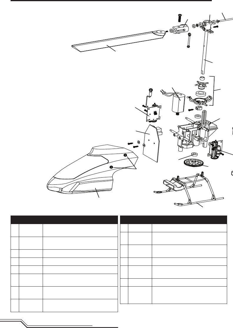
Exploded View and Parts Listings
Part # Description
ABLH3501 Flybarless3-in-1ControlUnit,
Receiver/ESCs/Gyros:mCPX
BBLH3502 TailBoomAssemblywithTailMotor/
Rotor/Mount:mCPX
CBLH3503 MainMotorwithPinion:mCPX
DBLH3504 LandingSkidandBatteryMount:mCPX
EBLH3505 MainFramewithhardware:mCPX
FBLH3506
EFLH3006 MainGear:BMSR,mCPX
G BLH3507 CarbonFiberMainShaftwithCollar
and Hardware: mCP X
HBLH3508 ServoPushrodSetwithBallLinks(3):
mCP X
Part # Description
IBLH3509 CompletePrecisionSwashplate:mCPX
JBLH3510 High-performanceMainRotorBladeSet
with Hardware: mCP X
BLH3511 FastFlightMainRotorBladeSetwith
Hardware: mCP X (not shown)
KBLH3512 MainRotorHubwithHardware:mCPX
L BLH3513 FeatheringSpindlewithO-rings,Bush-
ings, and Hardware: mCP X
M BLH3514 MainBladeGripswithBearings:mCPX
NBLH3515
EFLH2215 MainShaftBearing
3x6x2mm(2):BMCX/2/MSR,FHX,MH-
35,mCPX
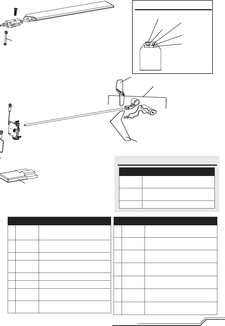
13 EN
A
B
O
Q
T
D
F
P
R
N
H (PITC)
CI
E
U (ELEV)
V (AILE)
G
S
J
MKL
Part # Description
OBLH3517
EFLH3017 TailRotor(1):BMSR,mCPX
PBLH3518 CompleteRedCanopywithVerticalFin:
mCP X
QBLH3520R RedVerticalFinwithDecal:mCPX
RBLH3521
EFLH3021 CanopyMountingGrommets(8):
BMCX2/T,MSR,FHX,MH-35,mCPX
S BLH3522 RotorHeadLinkageSet(8):mCPX
BLH3523 HardwareSet:mCPX(not shown)
TEFLB
2001S25 200mAh1S3.7V25CLi-PoBattery
EFLA
7002UM 1sHighCurrentUltra-MicroBattery
AdapterLead(not shown)
Part # Description
U SPMAS
2000LBB 1.8-GramLinearUltraMicroServo
V SPM6833 1.8-GramLinearUltraMicroServo
ReplacementServoMechanics
EFLC1005 ACto6VDC1.5-AmpPowerSupply(US)
(not shown)
EFLC
1005UK
ACto6VDC1.5-AmpPowerSupply(UK)
(not shown)
EFLC
1005EU
ACto6VDC1.5-AmpPowerSupply(EU)
(not shown)
EFLC
1005AU
ACto6VDC1.5-AmpPowerSupply(AU)
(not shown)
EFLC1006 Celectra1S3.7VariableRateDCLi-Po
Charger (not shown)
Part # Description
BLH3519 CompleteGreenCanopywithVertical
Fin: mCP X (not shown)
BLH3520G GreenVerticalFinwithDecal
(not shown)
EFLC1004 Celectra4portcharger
Aileron
Elevator
Pitch
Main Motor
Tail Motor
Optional Parts
Main Board Plug Configuration

14
EN
Warranty and Repair Policy
Warranty Period
ExclusiveWarranty-HorizonHobby,Inc.,(Horizon)war-
rantiesthattheProductspurchased(the“Product”)will
befreefromdefectsinmaterialsandworkmanshipatthe
date of purchase by the Purchaser.
Limited Warranty
Horizon reserves the right to change or modify this
warranty without notice and disclaims all other
warranties, express or implied.
(a)ThiswarrantyislimitedtotheoriginalPurchaser
(“Purchaser”)andisnottransferable.REPAIROR
REPLACEMENTASPROVIDEDUNDERTHISWARRANTY
ISTHEEXCLUSIVEREMEDYOFTHEPURCHASER.This
warranty covers only those Products purchased from
an authorized Horizon dealer. Third party transactions
are not covered by this warranty. Proof of purchase is
required for all warranty claims.
(b)Limitations-HORIZONMAKESNOWARRANTYOR
REPRESENTATION,EXPRESSORIMPLIED,ABOUT
NON-INFRINGEMENT,MERCHANTABILITYORFITNESS
FORAPARTICULARPURPOSEOFTHEPRODUCT.THE
PURCHASERACKNOWLEDGESTHATTHEYALONEHAVE
DETERMINEDTHATTHEPRODUCTWILLSUITABLYMEET
THEREQUIREMENTSOFTHEPURCHASER’SINTENDED
USE.
(c)PurchaserRemedy-Horizon’ssoleobligation
hereundershallbethatHorizonwill,atitsoption,(i)
repairor(ii)replace,anyProductdeterminedbyHorizon
to be defective. In the event of a defect, these are the
Purchaser’sexclusiveremedies.Horizonreservesthe
right to inspect any and all equipment involved in a
warranty claim. Repair or replacement decisions are
at the sole discretion of Horizon. This warranty does
not cover cosmetic damage or damage due to acts of
God,accident,misuse,abuse,negligence,commercial
use, or modification of or to any part of the Product.
This warranty does not cover damage due to improper
installation, operation, maintenance, or attempted repair
by anyone other than Horizon. Return of any Product
by Purchaser must be approved in writing by Horizon
before shipment.
Damage Limits
HORIZONSHALLNOTBELIABLEFORSPECIAL,INDIRECT
ORCONSEQUENTIALDAMAGES,LOSSOFPROFITSOR
PRODUCTIONORCOMMERCIALLOSSINANYWAYCON-
NECTEDWITHTHEPRODUCT,WHETHERSUCHCLAIM
ISBASEDINCONTRACT,WARRANTY,NEGLIGENCE,OR
STRICTLIABILITY.Further,innoeventshalltheliability
ofHorizonexceedtheindividualpriceoftheProducton
which liability is asserted. As Horizon has no control over
use, setup, final assembly, modification or misuse, no
liability shall be assumed nor accepted for any resulting
damage or injury. By the act of use, setup or assembly, the
user accepts all resulting liability.
If you as the Purchaser or user are not prepared to accept
the liability associated with the use of this Product, you
are advised to return this Product immediately in new and
unused condition to the place of purchase.
Law:TheseTermsaregovernedbyIllinoislaw(without
regardtoconictoflawprincipals).
WARRANTY SERVICES
Questions, Assistance, and Repairs
Yourlocalhobbystoreand/orplaceofpurchasecannot
provide warranty support or repair. Once assembly, setup
or use of the Product has been started, you must contact
Horizon directly. This will enable Horizon to better answer
your questions and service you in the event that you may
need any assistance. For questions or assistance, please
direct your email to productsupport@horizonhobby.com,
orcall877.504.0233tollfreetospeaktoaProductSup-
portrepresentative.Youmayalsondinformationonour
website at www.horizonhobby.com.
Inspection or Repairs
If this Product needs to be inspected or repaired, please
use the Horizon Online Repair Request submission
process found on our website or call Horizon to obtain a
ReturnMerchandiseAuthorization(RMA)number.Pack
the Product securely using a shipping carton. Please Note
thatoriginalboxesmaybeincluded,butarenotdesigned
to withstand the rigors of shipping without additional
protection.Shipviaacarrierthatprovidestrackingand
insurance for lost or damaged parcels, as Horizon is not
responsible for merchandise until it arrives and is ac-
cepted at our facility. An Online Repair Request is available
at www.horizonhobby.com under the Repairs tab. If you do
not have internet access, please contact Horizon Product
SupporttoobtainaRMAnumberalongwithinstruc-
tions for submitting your product for repair. When calling
Horizon,youwillbeaskedtoprovideyourcompletename,
street address, email address and phone number where
you can be reached during business hours. When sending
productintoHorizon,pleaseincludeyourRMAnumber,a
list of the included items, and a brief summary of the prob-
lem. A copy of your original sales receipt must be included
for warranty consideration. Be sure your name, address,
andRMAnumberareclearlywrittenontheoutsideofthe
shipping carton.
Notice: Do not ship batteries to Horizon. If you have
any issue with a battery, please contact the appropri-
ate Horizon Product Support office.
Warranty Inspection and Repairs
To receive warranty service, you must include your
original sales receipt verifying the proof-of-purchase
date. Provided warranty conditions have been met, your
Product will be repaired or replaced free of charge. Repair
or replacement decisions are at the sole discretion of
Horizon.
Non-Warranty Repairs
Should your repair not be covered by warranty the
repair will be completed and payment will be required
without notification or estimate of the expense unless
the expense exceeds 50% of the retail purchase cost.
By submitting the item for repair you are agreeing to pay-
ment of the repair without notification. Repair estimates
areavailableuponrequest.Youmustincludethisrequest
with your repair. Non-warranty repair estimates will
be billed a minimum of ∏ hour of labor. In addition you
will be billed for return freight. Horizon accepts money
ordersandcashierschecks,aswellasVisa,MasterCard,
AmericanExpress,andDiscovercards.Bysubmittingany
item to Horizon for inspection or repair, you are agreeing
to Horizon’s Terms and Conditions found on our website
under the Repairs tab.
17 EN
Declaration of Conformity
(inaccordancewithISO/IEC17050-1)
No.HH2011010902
Product(s): BlademCPXBNF
ItemNumber(s): BLH3580EU,BLH3580UK
Equipmentclass: 1
The object of declaration described above is in conformity with the requirements of the specifications listed below,
followingtheprovisionsoftheEuropeanR&TTEDirective1999/5/ECandEMCDirective2004/108/EC:
EN 301 489-1, 301 489-17
EN 301 489-1, 301 489-3 GeneralEMCrequirements
EN55022 Radio disturbance characteristics
EN55024 Immunity characteristics
EN55014 Immunity characteristics
EN61000-3-2 Harmonic current emissions
EN61000-3-3 Voltageuctuations&icker
Signedforandonbehalfof:
Horizon Hobby, Inc.
Champaign,ILUSA
Jan9,2011
StevenA.Hall
VicePresident
InternationalOperationsandRiskManagement
Horizon Hobby, Inc.
Instructions for disposal of WEEE by users in the European Union
This product must not be disposed of with other waste. Instead, it is the user’s responsibility to dispose of
their waste equipment by handing it over to a designated collections point for the recycling of waste electri-
cal and electronic equipment. The separate collection and recycling of your waste equipment at the time of
disposalwillhelptoconservenaturalresourcesandmakesurethatitisrecycledinamannerthatprotects
human health and the environment. For more information about where you can drop off your waste equip-
ment for recycling, please contact your local city office, your household waste disposal service or where you
purchased the product.

15 EN
Country of
Purchase Horizon Hobby Address Phone Number/Email Address
UnitedStatesof
America
HorizonServiceCenter
(Electronicsandengines)
4105FieldstoneRd
Champaign, Illinois
61822USA
877-504-0233
Online Repair Request:
visit www.horizonhobby.com/repairs
HorizonProductSupport
(Allotherproducts)
4105FieldstoneRd
Champaign, Illinois
61822USA
877-504-0233
productsupport@horizonhobby.com
UnitedKingdom HorizonHobbyLimited
Units1-4PloytersRd
StapleTye
Harlow,Essex
CM187NS
UnitedKingdom
+44(0)1279641097
sales@horizonhobby.co.uk
Germany Horizon Technischer
Service
HamburgerStr.10
25335Elmshorn
Germany
+4941214619966
service@horizonhobby.de
France HorizonHobbySAS
14RueGustaveEiffel
Zoned’ActivitéduRéveilMatin
91230Montgeron
+33(0)160474470
infofrance@horizonhobby.com
Warranty and Service Contact Information
Customer Service Information
Country of
Purchase Horizon Hobby Address Phone Number/Email Address
UnitedStatesof
America Sales
4105FieldstoneRd
Champaign, Illinois
61822USA
(800)338-4639
sales@horizonhobby.com
UnitedKingdom HorizonHobbyLimited
Units1-4PloytersRd
StapleTye
Harlow,Essex
CM187NS
UnitedKingdom
+44(0)1279641097
sales@horizonhobby.co.uk
Germany HorizonHobbyGmbH
HamburgerStr.10
25335Elmshorn
Germany
+4941214619960
service@horizonhobby.de
France HorizonHobbySAS
14RueGustaveEiffel
Zoned’ActivitéduRéveilMatin
91230Montgeron
+33(0)160474470
infofrance@horizonhobby.com

16
EN
Declaration of Conformity
Compliance Information for the European Union
(inaccordancewithISO/IEC17050-1)
No.HH2011010901
Product(s): BlademCPXRTF
ItemNumber(s): BLH3500EU1(EUmode1),BLH3500EU2(EUmode2),
BLH3500UK1(UKmode1),BLH3500UK2(UKmode2)
Equipmentclass: 2
The object of declaration described above is in conformity with the requirements of the specifications listed below,
followingtheprovisionsoftheEuropeanR&TTEDirective1999/5/EC,EMCDirective2004/108/ECandLVDDirective
2006/95/EC:
EN 300-328 Technical requirements for Radio equipment.
EN 301 489-1, 301 489-17
EN 301 489-1, 301 489-3 GeneralEMCrequirements
EN 60950 Safety
EN55022 Radio disturbance characteristics
EN55024 Immunity characteristics
EN55014 Immunity characteristics
EN61000-3-2 Harmonic current emissions
EN61000-3-3 Voltageuctuations&icker
Signedforandonbehalfof:
Horizon Hobby, Inc.
Champaign,ILUSA
Jan9,2011
StevenA.Hall
VicePresident
InternationalOperationsandRiskManagement
Horizon Hobby, Inc.
FCC Information
Thisdevicecomplieswithpart15oftheFCCrules.Operationissubjecttothefollowingtwoconditions:(1)This
devicemaynotcauseharmfulinterference,and(2)thisdevicemustacceptanyinterferencereceived,including
interference that may cause undesired operation.
CAUTION:Changesormodicationsnotexpresslyapprovedbythepartyresponsibleforcompliancecould
void the user’s authority to operate the equipment.
This product contains a radio transmitter with wireless technology which has been tested and found to be
compliantwiththeapplicableregulationsgoverningaradiotransmitterinthe2.400GHzto2.4835GHzfrequency
range.
AT BG CZ CY DE
DK ES FI FR GR
HU IE IT LT LU
LV MT NL PL PT
RO SE SI SK UK

©2011HorizonHobby,Inc
E-ite,Celectra,JRandDSMaretrademarksorregisteredtrademarksofHorizonHobby,Inc.
TheSpektrumtrademarkisusedwithpermissionofBachmannIndustries,Inc.
USpatentnumber7,391,320.USD578,146.PRCZL200720069025.2Otherpatentspending.
Created12/1027560BLH3500/BLH3580
