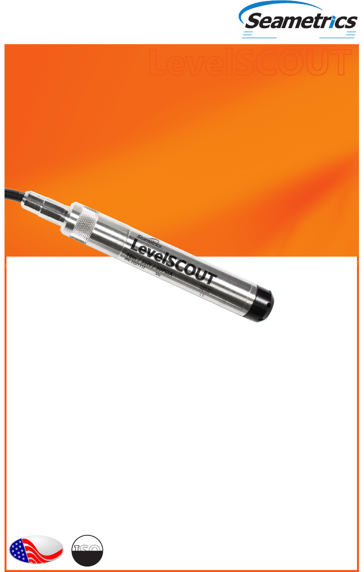
LevelSCOUT Instructions Seametrics Level SCOUT
User Manual: Manual
Open the PDF directly: View PDF ![]() .
.
Page Count: 36
PROUDLY
MADE
IN THE
USA
C
e
r
t
i
f
i
e
d
C
o
m
p
a
n
y
ISO
9001:2008
Precision Environmental Sensors
An ON
I
CON Brand
LevelSCOUT
Level/Temperature
Smart Sensor and Datalogger
For Sales & Service Contact
2650 E. 40th Ave. • Denver, CO 80205
Phone 303-320-4764 • Fax 303-322-7242
1-800-833-7958
www.geotechenv.com

LEVELSCOUT INSTR
Seametrics • 253.872.0284 Page 2 seametrics.com
©1997 - 2016 Seametrics. All rights reserved.
Registered trademarks and trademarks belong to their respective owners.

LEVELSCOUT INSTR
Seametrics • 253.872.0284 Page 3 seametrics.com
General Information
What is the LevelSCOUT? .....................................................................................................................4
Initial Inspection and Handling ..........................................................................................................4
Do’s and Don’ts ........................................................................................................................................5
How Pressure/Level Sensors Work....................................................................................................5
General Specication..............................................................................................................................6
Wiring and Component Information ...............................................................................................7
Installation
Power ............................................................................................................................................................8
Connecting the LevelSCOUT to a Computer ................................................................................8
Installing the Aqua4Plus 2.0 Software .............................................................................................8
Installing the Sensor ...............................................................................................................................9
Battery Life Calculator ............................................................................................................................9
Connecting via RS232 Serial Port ................................................................................................... 10
Connecting via USB/Serial Adapter ............................................................................................... 10
Connecting to Sensors........................................................................................................................ 11
Settings and Calibration
A Word About Units ............................................................................................................................ 12
Sensor Settings ...................................................................................................................................... 12
Program Settings .................................................................................................................................. 13
Pressure Calibration ............................................................................................................................. 15
Operation
Real-time Data ....................................................................................................................................... 19
Data Logging .......................................................................................................................................... 20
Reports ...................................................................................................................................................... 24
Barometric Compensation ............................................................................................................... 27
Direct Read Modbus/SDI-12
Settings Units for Direct Read .......................................................................................................... 30
Reading Via Modbus RTU .................................................................................................................. 31
Maintenance
Changing Batteries ............................................................................................................................... 32
Miscellaneous ......................................................................................................................................... 32
Troubleshooting
Erratic Readings ..................................................................................................................................... 33
Zero Readings When Pressurized ................................................................................................... 33
Grounding Issues .................................................................................................................................. 33
Warranty ............................................................................................................ 35
TABLE OF CONTENTS

LEVELSCOUT INSTR
Seametrics • 253.872.0284 Page 4 seametrics.com
What is the LevelSCOUT?
The Seametrics LevelSCOUT Smart Sensor is an integrated datalogger and level/temperature
sensor and is ideal for site assessments, tidal studies, environmental monitoring, surface
water discharge measurement, and aquifer level monitoring, as well as aquifer storage and
recovery. This sensor networks with all of the Seametrics Smart Sensor family.
This industry standard digital RS485 interface device records up to 50,000 records of level,
temperature, and time data, operates with low power, and features easy-to-use software
with powerful features. Constructed with 316 stainless steel, acetal, and Viton®, this sensor
provides high-accuracy readings in rugged and corrosive eld conditions.
The LevelSCOUT is an absolute sensor, requiring no vent tubes, desiccant, or bellows. It can
be paired with a BaroSCOUT barometric sensor and used with the Aqua4Plus 2.0 Barometric
Compensation Utility to adjust the LevelSCOUT readings for current atmospheric pressure.
A 1/2 AA 3.6v lithium battery powers the LevelSCOUT. The unit is programmed using
Seametrics’ easy-to-use Aqua4Plus 2.0 control software. Once programmed the unit will
measure and collect data at the time interval programmed.
Replace your analog sensor/datalogger with the Seametrics LevelSCOUT as a stand-
alone unit or network with other Seametrics Smart Sensors. While most will use the
LevelSCOUT with Seametrics Aqua4Plus 2.0 software, it is by no means limited to
that software. You can use your own Modbus® RTU software or logging equipment
to read measurements via RS485, tying into your existing systems and data bases.
Initial Inspection and Handling
Upon receipt of your smart sensor, inspect the shipping package for damage. If any
damage is apparent, note the signs of damage on the appropriate shipping form. After
opening the carton, look for concealed damage, such as a cut cable. If concealed damage
is found, immediately le a claim with the carrier.
Check the etched label on the sensor to be sure that the proper range and type were
provided. Also check the label attached to the cable at the connector end for the proper
cable length.
GENERAL INFORMATION

LEVELSCOUT INSTR
Seametrics • 253.872.0284 Page 5 seametrics.com
How Pressure/Level Sensors Work
Liquids and gasses do not retain a xed shape. Both have the ability to ow and are often
referred to as uids. One fundamental law for a uid is that the uid exerts an equal
pressure in all directions at a given level. Further, this pressure increases with an increasing
depth of “submergence”. If the density of a uid remains constant (noncompressible...a
generally good assumption for water at “normal” pressures and temperatures), this
pressure increases linearly with the depth of “submergence”.
We are all “submerged” in the atmosphere. As we increase our elevation, the pressure
exerted on our bodies decreases as there is less of this uid above us. It should be noted
that atmospheric pressure at a given level does vary with changes in the weather. One
standard atmosphere (pressure at sea level at 20º C) is dened to be 14.7 PSI (pounds per
square inch).
There are several methods to reference a pressure measurement. Absolute pressure is
measured with respect to an ideal vacuum (no pressure). Gauge pressure is the most
common way we express pressure in every day life and is the pressure exerted over and
above atmospheric pressure. With this in mind, gauge pressure (Pg) can be expressed
as the dierence between the absolute pressure (Pa) and atmospheric pressure (Patm):
Pg = Pa - Patm.
The LevelSCOUT is an absolute sensor and will require an outside barometric reference
to obtain “gauge” type readings.
GENERAL INFORMATION
Do handle the device with care.
Do store the device in a dry, inside
area when not in use.
Do install the device so that the
cable connector is kept dry.
Don’t support the device with the connector.
Use a strain relief device to take the
tension o the connectors.
Don’t allow the device to free-fall down a well
as impact damage can occur.
Don’t bang or drop the device on hard
objects.
Do’s and Don’ts

LEVELSCOUT INSTR
Seametrics • 253.872.0284 Page 6 seametrics.com
General Specication
The Seametrics LevelSCOUT is a microprocessor based digital intelligent sensor designed
to measure and record level, temperature, and time, utilizing state-of-the-art low power,
battery operated circuitry.
Level is measured with an extremely rugged and stable piezo-electric media-isolated
pressure element combined with an analog-to-digital converter. This provides extremely
accurate and stable pressure input into the microprocessor on the circuit board.
Temperature is measured with an epoxy bead thermistor. The data is stored in non-
volatile memory. A serial communication link (RS485) provides communication to the
host computer.
Length (cabled version) 6.6” (16.7 cm)
Length (cableless version) 5.1” (12.9 cm)
Diameter 0.875” (2.22 cm)
Body Material 316 stainless steel or titanium
Wetted Materials 316 stainless steel or titanium, acetal, uoropolymer
Communication RS485 Modbus® RTU
Direct Modbus Read Output 32-bit IEEE oating point
Internal Math 32-bit oating point
Operating Temp. Range -20° C to 60° C
Storage Temp. Range -40° C to 80° C
Logging
Memory 50,000 records
Logging Rate 1x per second
Software Complimentary Aqua4Plus 2.0
File Formats .csv / .a4d
Power
Internal Battery One 1/2 AA 3.6 lithium battery
Expected Battery Life 4.5 years (depending on use)
Temperature
Element Type Thermistor
Accuracy ± 0.1° C
(from -20° C to 60° C)
Resolution 0.01° C
Units Celsius, Fahrenheit, Kelvin
GENERAL INFORMATION
LEVELSCOUT INSTR
Seametrics • 253.872.0284 Page 7 seametrics.com
Level
Transducer Type Silicon strain gauge
Transducer Material 316 stainless steel
Ranges
Absolute1
PSI
FtH2O (max. depth)
mH2O (max. depth)
30, 50, 100, 300
35, 81, 196, 658
10, 24, 59, 200
Units PSI, FtH2O, inH2O, cmH2O, mmH2O, mH2O, inHg,
cmHg, mmHg, Bars, mBars, kPa
Accuracy ± 0.05% FS (@ 20° C)
± 0.10% FS (0° C to 40° C)
Resolution 0.0034% FS (typical)
Maximum Operating Pressure 1.1 x FS
Over Range Protection 3x FS (for >300 psi2, 1.75 FS)
Burst Pressure 600 psi (approx. 1350 ft or 410 m)
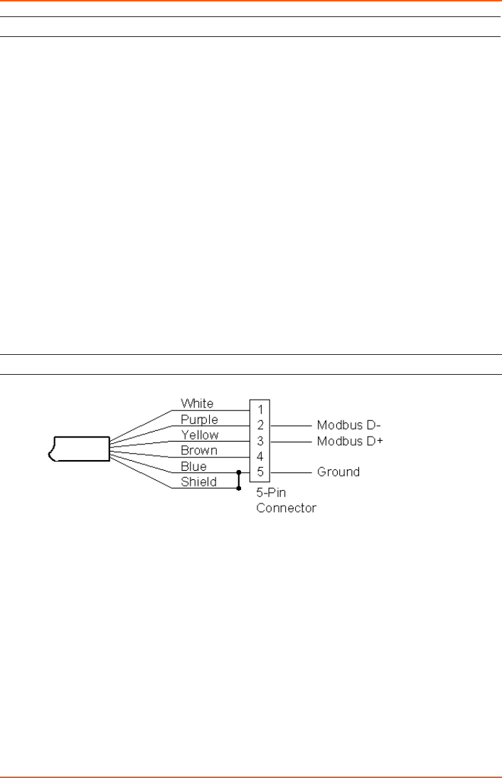
Wiring and Component Information
¹Depth range has 15 PSI subtracted to give actual depth allowed.
²Approx. 658 feet or 200 meters
GENERAL INFORMATION
LEVELSCOUT INSTR
Seametrics • 253.872.0284 Page 8 seametrics.com
Power
The LevelSCOUT comes with a 1/2 AA 3.6v lithium battery.
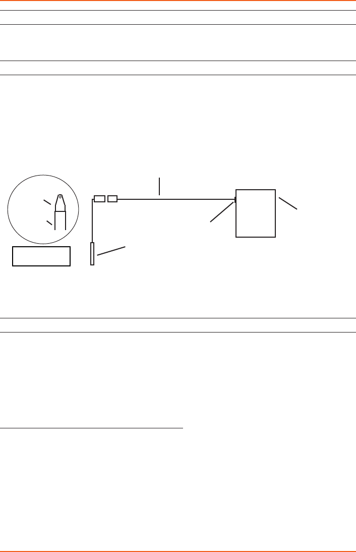
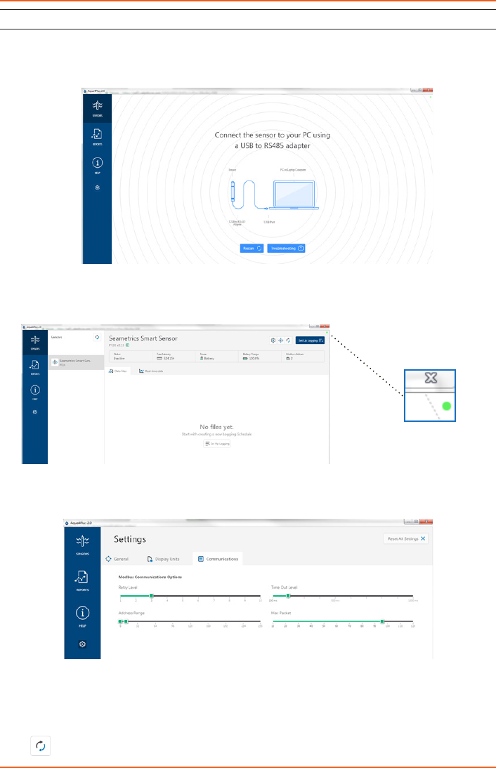
Connecting the LevelSCOUT to a Computer
In its cabled conguration, the sensor cable is terminated with a weather-resistant
connector. In its cableless conguration, the sensor is terminated with a weather-
resistant connector inside a screw-cap. Connect the weather-resistant connector to
your computer’s USB port as shown below.
Connect the sensor to your PC using Seametrics’ USB to RS485
adapter.
Installing the Aqua4Plus 2.0 Software
The LevelSCOUT comes with the Aqua4Plus 2.0 host software that is installed on your PC
or laptop. Use this software to program the datalogger, to retrieve data from the logger,
to view collected data, and to export data to external les for use with spreadsheets or
databases.
Refer to the Aqua4Plus 2.0 software manual for details on installing and using the software.
LevelSCOUT can also be used with the full Aqua4Plus 2.0 software.
Using the LevelSCOUT Without Aqua4Plus 2.0
Most users will use the LevelSCOUT with Seametrics Aqua4Plus 2.0 software. However, the
LevelSCOUT is quite versatile, communicating via Modbus® RTU, allowing you to use your
own software or logging equipment.
PC or Laptop
Computer
USB Port
USB to RS485
Adapter
Sensor
Cableless
Conguration
Screw-
Sensor
cap
INSTALLATION

LEVELSCOUT INSTR
Seametrics • 253.872.0284 Page 9 seametrics.com
Installing the Sensor
The LevelSCOUT measures level. The most common application is measuring liquid levels
in wells and tanks. In order to do this, the sensor must be installed below the water
level at a xed depth. The installation depth depends on the range of the sensor. The
sensor should not be installed below its maximum depth. If the sensor is installed below
its maximum depth, damage may result to the sensor and the output reading will not be
correct.
Note: If you are using an absolute sensor and you want to enter a depth-to-water
reference after data is collected, then see Appendix E before proceeding.
• Lower the sensor to the desired depth.
• Fasten the cable to the well head using tie wraps or a weather proof strain-relief
system.
• Take a measurement to insure the sensor is not installed below its maximum range.
Be sure the supplied cap is securely placed on the weather-resistant connector at the
top of the cable. Do not install such that the connector might become submerged with
changing weather conditions. The connector can withstand incidental splashing but is not
designed to be submerged.
The sensor can be installed in any position; however, when it leaves the factory it is
tested in the vertical position. Strapping the sensor body with tie wraps or tape will
not hurt it. If the sensor is being installed in a uid environment other than water,
be sure to check the compatibility of the uid with the wetted parts of the sensor.
Battery Life Calculator
The LevelSCOUT has a battery life calculator that is set at the factory when batteries are
rst put in the sensor. If you need to replace the batteries, see the Maintenance section
for replacement information and for information on resetting the battery life calculator.
If the battery life calculator is not reset, the remaining life information will be
incorrect.
INSTALLATION
LEVELSCOUT INSTR
Seametrics • 253.872.0284 Page 10 seametrics.com
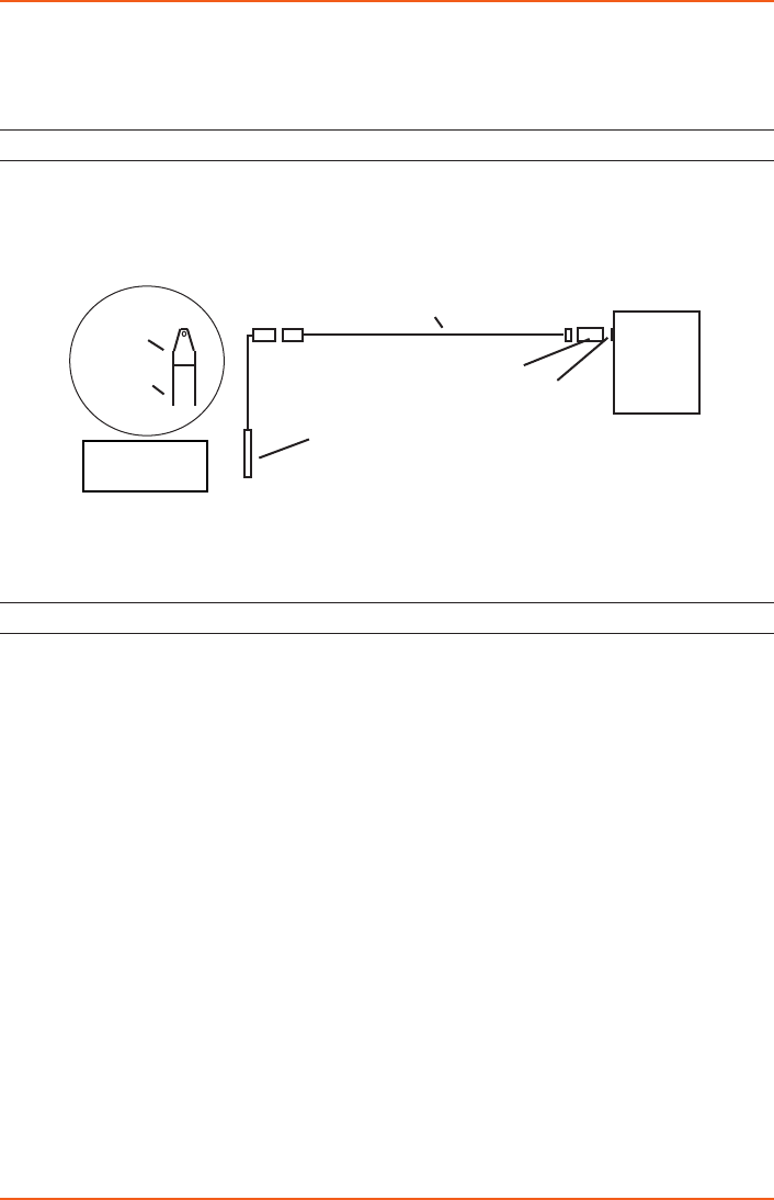
Seametrics recommends connecting the sensor to your computer using the Seametrics
USB cable. However, when using Aqua4Plus 2.0, the sensor can also be connected using
an RS232 serial port or a USB-to-Serial cable, as described below.
Connecting via RS232 Serial Port
In its cabled conguration, the sensor cable is terminated with a weather-resistant
connector. In its cableless conguration, the sensor is terminated with a weather-
resistant connector inside a screw-cap. Connect the weather-resistant connector to
your computer’s serial port as shown below.
Connect the sensor to your computer using an RS485/RS232 adapter and
an interface cable.
Connecting with a USB/Serial Adapter
USB-to-Serial cables are readily available from many electronics and computer stores,
as well as numerous sites on the Internet. Seametrics has tested and recommends the
Keyspan USA-19HS. It is available from Seametrics as well as from many sites on the
Internet. Install as follows:
• Plug into USB port.
• Install the drivers provided with the particular unit.
• Once drivers are installed, connect to sensor.
PC or
Laptop
Computer
RS485/RS232
Adapter
Interface Cable
Serial Port
Sensor
Screw-
Sensor
cap
Cableless
Conguration
INSTALLATION
LEVELSCOUT INSTR
Seametrics • 253.872.0284 Page 11 seametrics.com
INSTALLATION
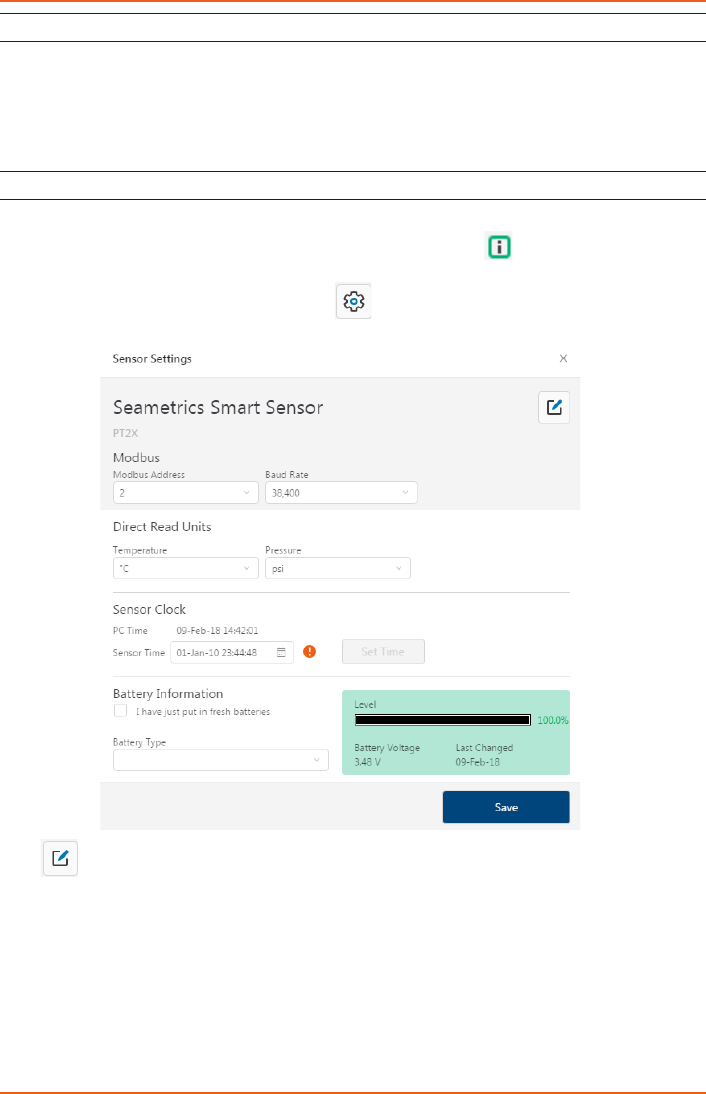
Connecting to Sensors
Aqua4Plus 2.0 is designed to automatically detect your communication cable and scan for
sensors. It is recommended you connect your USB/RS485 cable to your PC and have the
sensor connected before opening Aqua4Plus 2.0.
If your cable and sensor were not connected before opening Aqua4Plus 2.0 simply connect
and click Rescan. While scanning is active you’ll see a green dot ash in the upper right
corner of the program. Scanning is complete when this dot stops ashing.
If your sensor still won’t connect you can expand the Modbus address range under
program settings here:
Simply drag the Address Range slider higher up to increase the maximum Modbus
address scanned. If you’ve scanned all the way up through address 255 and still have no
connection click Troubleshooting for further troubleshooting or contact Seametrics Tech
Support for assistance.
Click at any time to refresh sensor information.
LEVELSCOUT INSTR
Seametrics • 253.872.0284 Page 12 seametrics.com
A Word About Units
Readings from the PT2X Smart Sensor can be displayed in various units, such as PSI, Ft.
H2O, or mm H2O for pressure, or degrees Celsius or degrees Fahrenheit for temperature.
Select the units you want from Sensor settings.
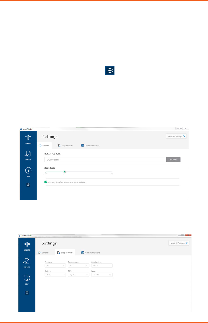
Sensor Settings
Once connected you’ll see the Sensor screen appear and display the connected sensor(s)
details. Mousing over icons will provide tool-tips, mouse over to view sensor rmware
and serial number details.
To change general sensor settings click in the sensor screen. This allows you to
change the following:
Click to rename the sensor
To change Modbus address and/or Baud Rate simply select the desired address and/or
Baud Rate from the drop down menus. Sensor will automatically reconnect at new address
and/or Baud Rate
To change the Direct Read output units (for direct Modbus or SDI12 integration) simply
select the desired output units from the drop down menus. To change Aqua4Plus 2.0
display units scaling see Program Settings.
SETTINGS AND CALIBRATION
LEVELSCOUT INSTR
Seametrics • 253.872.0284 Page 13 seametrics.com
Sensor Clock can be synced with your PC time or set manually if desired. To set manually
enter your desired date/time and click Set Time.
When batteries are changed out make sure to reset the battery information here, simply
check the I have just put in new batteries box and select the battery type that was installed
from the drop down menu.
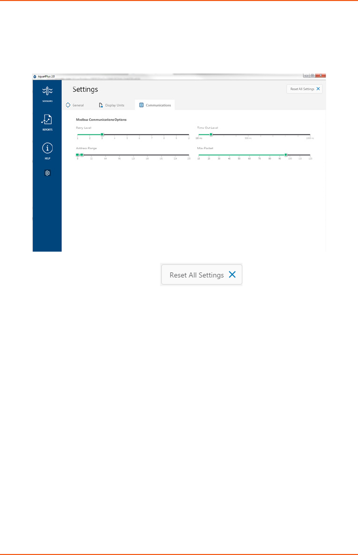
Program Settings
To view/change Aqua4Plus 2.0 settings click in the blue side-bar menu.
Under the General Settings tab you can change the default data folder location. This is
where your Reports are saved to on your PC.
The Zoom Factor slider can be used to adjust the font size within Aqua4Plus 2.0.
Uncheck the Allow app to collect anonymous usage statistics box if you would like to
opt out. This information is used to track Aqua4Plus 2.0 reliability across dierent system
congurations.
Under the Display Units tab you can select your desired display units for the supported
channels. These may be changed at any time and associated Real-Time readings and
Reports will rescale to the currently selected display unit. To change Direct Read units
scaling see Sensor Settings.
SETTINGS AND CALIBRATION
LEVELSCOUT INSTR
Seametrics • 253.872.0284 Page 14 seametrics.com
SETTINGS AND CALIBRATION
Under the Communications tab you can change your Modbus communication settings.
Typically you will only need to change the address range to connect to sensors outside
of Modbus address 1-10. In certain cases we may need to change the Retry and Timeout
settings to overcome communication issues on very long, or corroded cabling. See
Troubleshooting section or contact Seametrics Tech Support for details.
To restore factory default settings click
LEVELSCOUT INSTR
Seametrics • 253.872.0284 Page 15 seametrics.com
SETTINGS AND CALIBRATION
Pressure Calibration
To perform a calibration setup on the pressure channel rst connect to the sensor and
ensure all data has been uploaded and erased from the sensor. Next select the calibration
button.
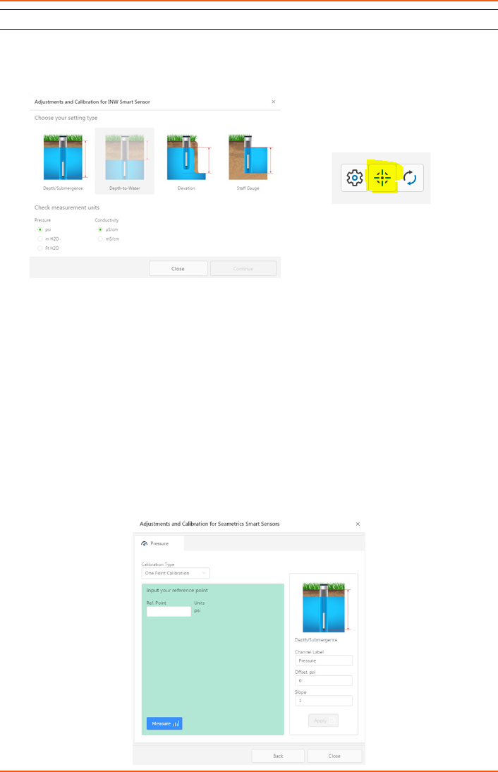
Next select the calibration setup you’d like to perform:
Conrm desired measurement units and click Continue.
Submergence:
One Point/Zero Point Calibration:
To zero pressure output to atmospheric pressure position the sensor in air in its desired
installation position (typically vertical, if sensor will be installed horizontally position as
such during 0 point calibration). Select 1 point Calibration under Calibration Type.
For PSIG sensors use 0 as the reference value and click Measure.
For PSIA sensors enter current barometric pressure from a known accurate barometer set
to matching units. Enter your reference value in the Ref. Point box and click Measure.
LEVELSCOUT INSTR
Seametrics • 253.872.0284 Page 16 seametrics.com
SETTINGS AND CALIBRATION
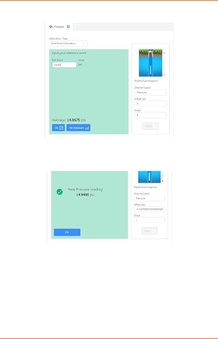
Aqua4Plus 2.0 will take 10 readings and display the average. Watch for stability while the
software is measuring to ensure an accurate calibration.
Click Ok to accept the reading and Aqua4Plus 2.0 will calculate a new pressure oset. Click
Apply to conrm the new oset value and Aqua4Plus 2.0 will provide a real time reading
to verify calibration was successful:
2 Point submergence calibration ONLY RECOMMENDED IF YOU HAVE AN ACCURATE
PRESSURE REFERENCE. Our Smart Sensors rarely change slope during normal use,
however if you have an accurate pressure source it is possible to perform a 2 point
calibration on the pressure channel.
Select 2 point Calibration under Calibration Type
Perform rst point calibration as listed above and click Next

LEVELSCOUT INSTR
Seametrics • 253.872.0284 Page 17 seametrics.com
SETTINGS AND CALIBRATION
Enter known pressure value in matching units in the Ref. Point box for second point
measurement
Aqua4Plus 2.0 will take 10 measurements and display the average. Watch for stability
while the software is measuring to ensure an accurate calibration.
Click Ok and Aqua4Plus 2.0 will calculate the new slope and oset values. Click Apply to
conrm the new slope and oset values and the software will provide a real time reading
to verify calibration was successful.
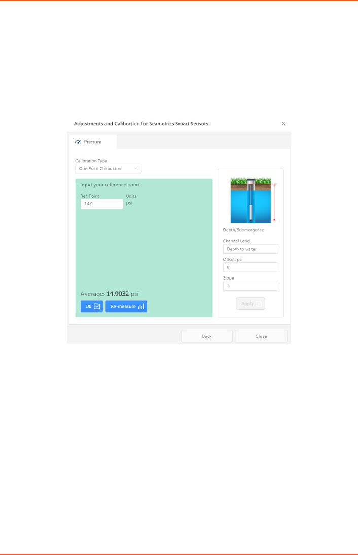
Groundwater Elevation
Position the sensor in its desired location and ensure all data has been uploaded and
erased from the sensor before proceeding with calibration.
Once positioned connect to sensor and select the calibration button, followed by selecting
the Groundwater Elevation option. Double check measurement units selection before
proceeding.
Enter your current Groundwater Elevation reading in the Ref. Point box, making sure to
match measurement units.
Click Measure and Aqua4Plus 2.0 will take 10 readings and display the average. Watch for
stability while the software is measuring to ensure an accurate calibration.
Click Accept and Aqua4Plus 2.0 will calculate a new oset, click Apply to accept the
new oset and Aqua4Plus 2.0 will provide a real time reading to verify calibration was
successful.
Sta Gauge
Position the sensor in its desired location and ensure all data has been uploaded and
erased from the sensor before proceeding with calibration.
Once positioned connect to sensor and select the calibration button, followed by selecting
the Sta Gauge option. Double check measurement units selection before proceeding.
Enter your current Sta Gauge reading in the Ref. Point box, making sure to match
measurement units.
LEVELSCOUT INSTR
Seametrics • 253.872.0284 Page 18 seametrics.com
SETTINGS AND CALIBRATION
Click Measure and Aqua4Plus 2.0 will take 10 readings and display the average. Watch for
stability while the software is measuring to ensure an accurate calibration.
Click Accept and it will calculate a new oset, click Apply to accept the new oset and
Aqua4Plus 2.0 will provide a real time reading to verify calibration was successful.
Removing calibration setup values
To return to factory default simply enter an oset of 0 and slope of 1 in the Oset and
Slope boxes:
Click Apply to conrm settings and Aqua4Plus 2.0 will provide a real time reading to
conrm.
Adjusting for specic gravity
You man enter the specic gravity of your uid in the Slope eld to adjust for specic
gravity when needed. Click Apply to conrm settings and Aqua4Plus 2.0 will provide a real
time reading to conrm.
LEVELSCOUT INSTR
Seametrics • 253.872.0284 Page 19 seametrics.com
OPERATION
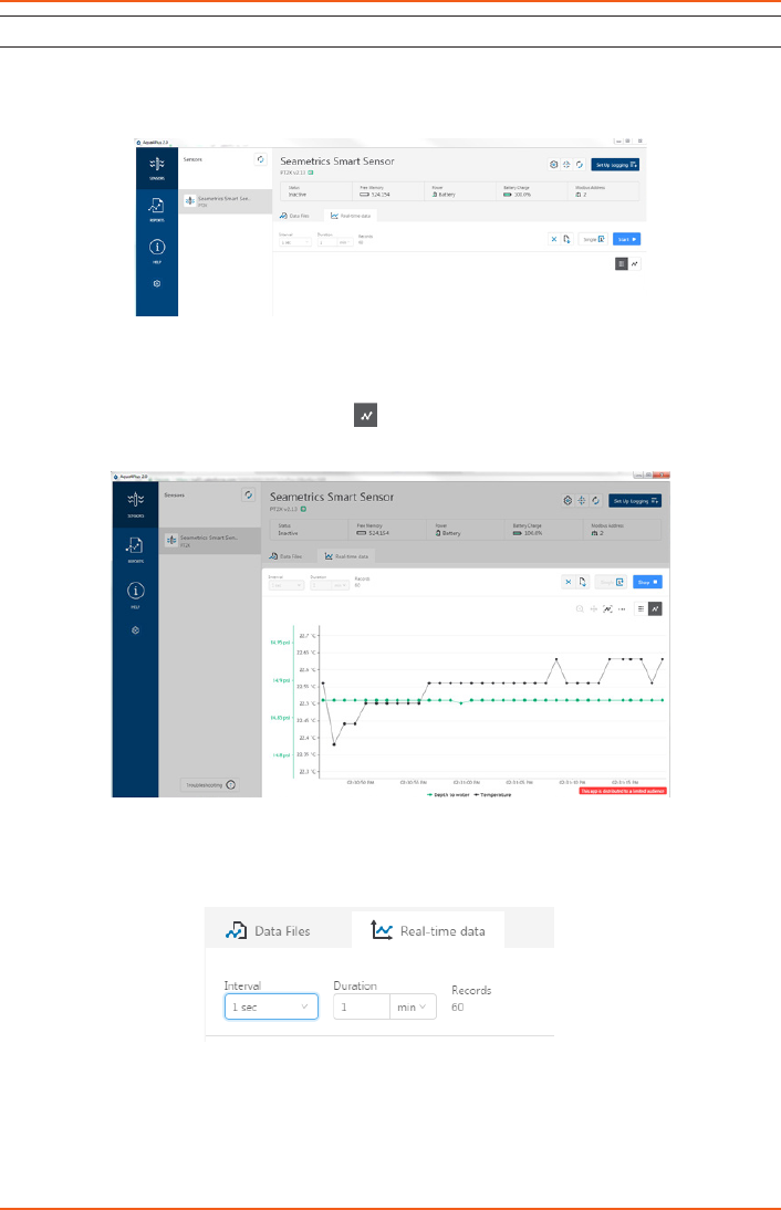
Real-time Data
Connect to sensor and select the Real-time data tab
To sytart real-time readings click Start, readings default to table view. To switch to Real-
time graphing view click the graph icon
Real-time readings default to a 1 second interval for 1 minute, to adjust enter your desired
settings here:
Note: Currently this data is not saved and is for viewing current conditions only. To save
the data to sensor memory see Data Logging section. You can run Real-time Data while
logging is active.
LEVELSCOUT INSTR
Seametrics • 253.872.0284 Page 20 seametrics.com
OPERATION
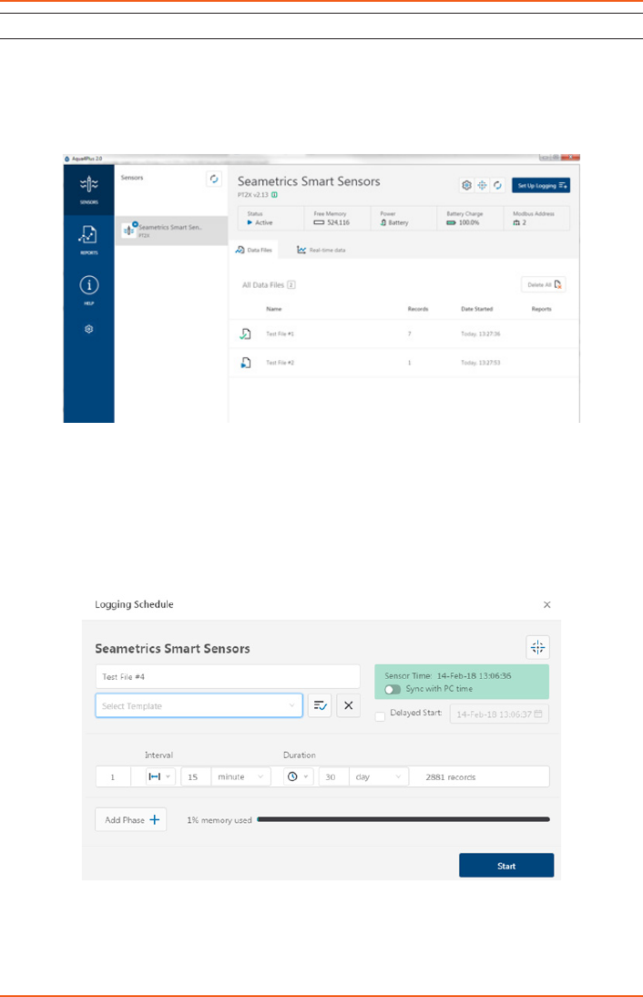
Data Logging
Select Set Up Logging from the sensor screen. If there are no les currently on the sensor
you’ll see the Set Up Logging button active under the Data Files tab as well as in the upper
menu. Once les have been started/logged on the sensor they will be displayed under the
Data Files tab.
Set Up Logging Window
Here you will name your data le and set up the recording interval and duration of
each logging phase. Select your desired recording interval and duration for each phase,
Aqua4Plus 2.0 will display the available memory at the bottom of the window.
LEVELSCOUT INSTR
Seametrics • 253.872.0284 Page 21 seametrics.com
OPERATION
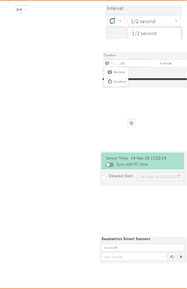
Click to switch between interval and
continuous data recording (PT2X & CT2X
only) Select your continuous rate from the
drop down box (on the right).
Duration can be set by either number of
records or by setting a duration time, as
shown on the right.
When set by number of records the time of the recording phase will be displayed detailing
how long that phase will run. When set by time, the total number of records for that phase
will be displayed.
If you need to check settings or perform a calibration click before proceeding with
logging setup to switch to the Settings and Calibration screen.
You may sync the sensor clock with the PC
clock when starting logging by clicking the
slider shown on the right.
Check the Delayed Start box and enter the
desired date/time you would like logging
to start. This is useful for syncing data when
setting up multiple sensors on a site. Data will
start logging at the set date/time rather than
immediately when Start is pressed.
Data le name defaults to Test File # and may
be re-named here, like on the right.

LEVELSCOUT INSTR
Seametrics • 253.872.0284 Page 22 seametrics.com
OPERATION
The 3 previous Logging Schedules that were programmed to a sensor will be listed under
the Select Template drop down menu. There you will also nd pre-programmed logging
schedules such as 24 hour pump test, along with any custom logging schedules saved by
the user.
To save a logging schedule as a template enter desired settings and click This will
add your custom schedule to the Select Template menu.
Once all the desired settings are made simply click Start to begin logging.
This will return you to the Sensor screen and your status will change to Active with the
data le displayed under the Data Files tab. Mouse over an active le to pause, terminate,
download, or view logging setup details.

LEVELSCOUT INSTR
Seametrics • 253.872.0284 Page 23 seametrics.com
Data les already downloaded will show in
the Reports column, clicking here will bring
you to the reports screen to view the data.
See Reports section for details.
You may only have 1 active data le
recording on each sensor, however you can
store multiple les in memory if desired.
Starting a new le will automatically terminate the active logging and begin the new
logging schedule. Real-time data is available during active logging.
To delete les from memory make sure they
have all been downloaded to Reports. Files
are removed from memory all at once rather
than individually.
Once conrmed les are permanently
deleted from the sensor memory.
OPERATION
LEVELSCOUT INSTR
Seametrics • 253.872.0284 Page 24 seametrics.com
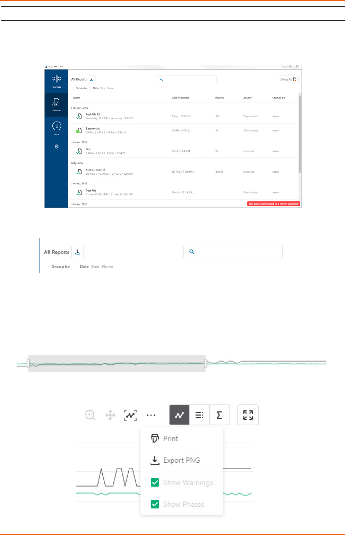
Reports
Data downloaded from your sensor is stored in the Reports section of Aqua4Plus 2.0 for
viewing and editing. The les will be saved to default data folder on your PC as well. See
Program Settings for default data folder location.
In the main view you’ll see a list of reports sorted by date, size, or le name as selected
here:
You can also search reports by keyword using the search box
Click on a report to bring up the report details.
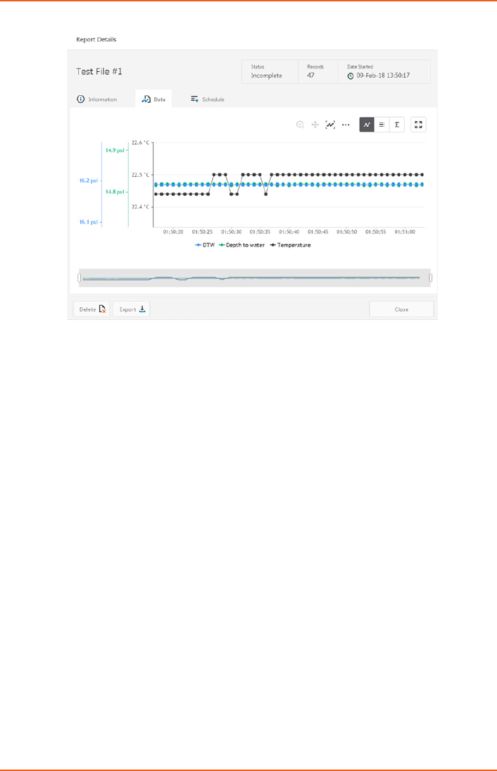
Reports are displayed in graphing view by default. You can zoom to specic sections by
selecting a section with you mouse or by adjusting the slider below the graph.
Graph saving and export options are available here
OPERATION
LEVELSCOUT INSTR
Seametrics • 253.872.0284 Page 25 seametrics.com
Click to switch to full screen graphing view
Click to view data as a table
Click to view data statistics
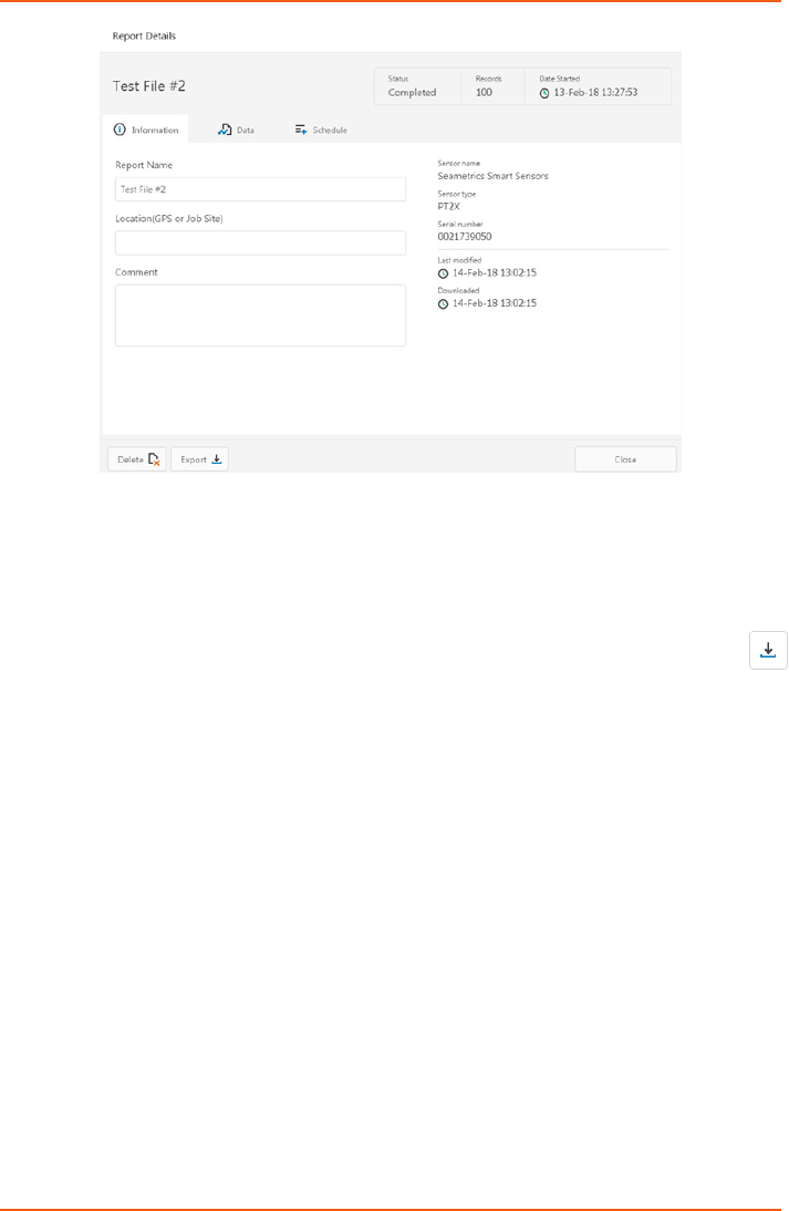
The Information tab is a new feature allowing users to add metadata to their reports
such as site location, eld notes, or comments.The Schedule tab will display the logging
setup details for the report
OPERATION
LEVELSCOUT INSTR
Seametrics • 253.872.0284 Page 26 seametrics.com
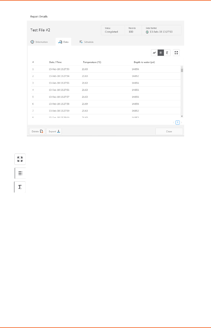
Click Export to export the report as a .csv le or .a4d le for distribution or use in 3rd
party software.
Click Delete to delete the report from Aqua4Plus 2.0
You can also import .a4d les from compatible sensors into Aqua4Plus 2.0 by clicking
at the top of the Reports screen.
OPERATION
LEVELSCOUT INSTR
Seametrics • 253.872.0284 Page 27 seametrics.com
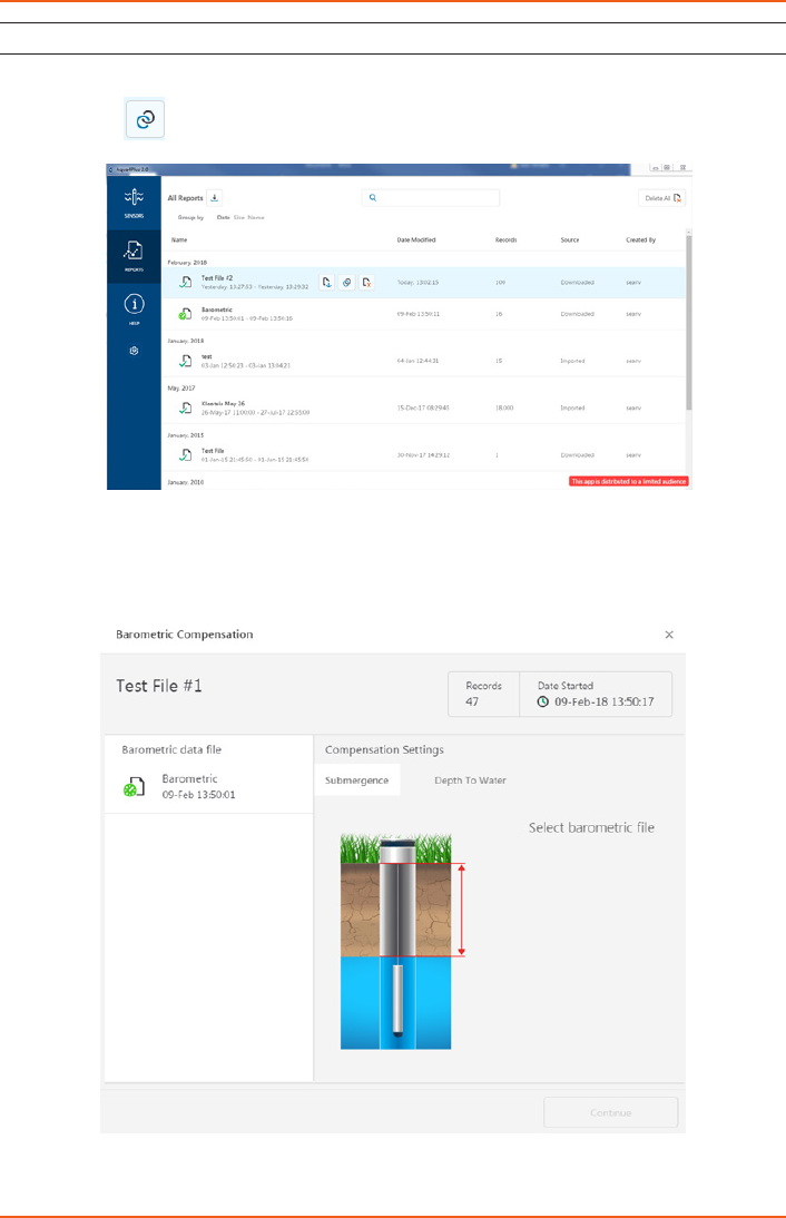
Barometric Compensation
For PSIA sensors we’ve built a new barometric compensation utility into the Reports
section. Click on a report to compensate the data for barometric pressure.
Corresponding barometric les are ltered by date/time and displayed to the left. Select
the barometric le you would like to use to compensate the report, select either the
Submergence or Depth To Water tab, then click Continue.
OPERATION
LEVELSCOUT INSTR
Seametrics • 253.872.0284 Page 28 seametrics.com
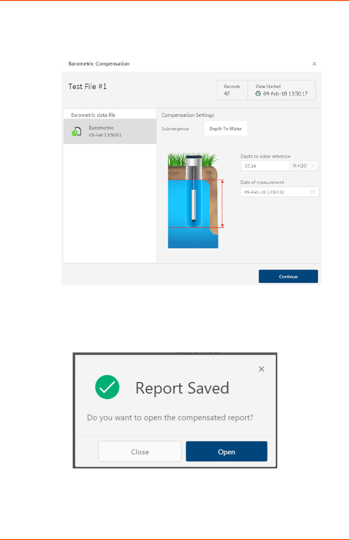
If compensating for Depth to Water enter your depth to water reference measurement
and the date/time the measurement was taken (typically taken with a water level indicator
before data is uploaded from the sensor) before clicking Continue.
Aqua4Plus 2.0 will perform the barometric compensation and create a new compensated
report. Original reports are retained as uploaded.
OPERATION
LEVELSCOUT INSTR
Seametrics • 253.872.0284 Page 29 seametrics.com
Compensated report can then be viewed and exported as needed.
OPERATION

LEVELSCOUT INSTR
Seametrics • 253.872.0284 Page 30 seametrics.com
While the LevelSCOUT comes with Seametrics’s easy to use Aqua4Plus 2.0 software, you
can also use standard Modbus® RTU equipment to easily take readings, so as to tie into
your existing equipment or networks.
Setting Units for Direct Read
By default, the LevelSCOUT uses the following units:
Temperature Degrees Celsius
Level PSI
However, you can select from a variety of units for direct read measurements. If you want
to change to dierent units, for example, degrees Fahrenheit for temperature or feet of
water for level, set these units using Aqua4Plus 2.0 (see sensor settings).
Once set, these units are saved on the sensor and direct readings will return values using
these units. (Note: These settings do not aect the units used on the Aqua4Plus 2.0 display.
Refer to the software manual for details.)
DIRECT READ MODBUS/SDI-12
LEVELSCOUT INSTR
Seametrics • 253.872.0284 Page 31 seametrics.com
Reading Via Modbus® RTU
Taking Measurements
Read measurements using Modbus function 03 – Read Holding Registers.
Readings are located in two registers each, starting at address 62592. (LevelSCOUT register
addressing is zero based, i.e., starts at zero. If your equipment uses one based addressing,
you will need to add one to the register addresses.)
Measurement Timing
When you request a reading via Modbus, the sensor wakes up, returns the current values
in the registers, and then starts taking new readings and updating the registers. After
approximately four seconds, if no more readings have been requested, the sensor goes
back to sleep.
Because of this, the rst reading you get will be old. If you are taking readings at intervals
of less than four seconds, simply ignore the rst reading — all remaining readings will
be current. On the other hand, if you are taking readings at intervals of greater than four
seconds, take a reading, ignore it, wait one second, take another reading. Record this
second reading.
Data Format
The data is returned as 32-bit IEEE oating-point values, highword rst, also referred to as
big-endian or oat inverse.
For further information and detailed Modbus examples, see Seametrics application note,
availabile on our website at www.seametric.com
Register addresses for LevelSCOUT
Zero Based One Based
Temperature 62592 62593
Pressure 62594 62595
DIRECT READ MODBUS/SDI-12

LEVELSCOUT INSTR
Seametrics • 253.872.0284 Page 32 seametrics.com
Changing Batteries
The LevelSCOUT is powered by a single 1/2 AA 3.6 lithium battery. In most situations
the battery will last for years. If you need to replace the battery, contact Seametrics for
information on getting it replaced. You cannot simply replace the battery itself but must
replace the entire compartment.
Miscellaneous
Sensor: There are no user-serviceable parts, other than the batteries. If problems develop
with sensor stability or accuracy, contact Seametrics. If the sensor has been exposed to
hazardous materials, do not return it without notication and authorization.
Cable: Cable can be damaged by abrasion, sharp objects, twisting, crimping, crushing,
or pulling. Take care during installation and use to avoid cable damage. If a section of
cable is damaged, it is recommended that you send your sensor back to replace the cable
harness assembly.
End Connections: The connectors used by Seametrics are not submersible, but are
designed to be splash-resistant.
IMPORTANT NOTE!
When changing batteries, it is important to reset the Battery Life Calculator.
If the battery life calculator is not reset, the remaining life information
will be incorrect. Access the Battery Life Calculator from the Congure Menu
- Battery Information and Reset. If you have put in new batteries, checkmark
the box “I have just put in fresh batteries.” Click Save and Close.
MAINTENANCE

LEVELSCOUT INSTR
Seametrics • 253.872.0284 Page 33 seametrics.com
Erratic Readings
Erratic readings can be caused by a poor connection, damaged cable, moisture in the unit,
or a damaged transmitter. In most cases, erratic readings are due to moisture getting
into the system. The rst thing to check is the connection. Look for moisture between
contacts or a loose or broken wire. Next, check the cable for cracking or fraying. If
the connections and cable appear OK, but the readings are still erratic, the transmitter
may be damaged. Contact Seametrics for evaluation and repair. Erratic and erroneous
readings can also occur due to improper grounding. See Grounding Issues, below.
Zero Readings When Pressurized
Continuous zero readings are usually caused by an open circuit which may
indicate a broken cable, a bad connection, or possibly a damaged transmitter.
Check the connector to see if a wire has become loose or if the cable has been cut.
If damage is not readily apparent, contact Seametrics for evaluation and repair.
Grounding Issues
It is commonly known that when using electronic equipment, both personnel and
equipment need to be protected from high power spikes that may be caused by lightning,
power line surges, or faulty equipment. Without a proper grounding system, a power
spike will nd the path of least resistance to earth ground – whether that path is through
sensitive electronic equipment or the person operating the equipment. In order to ensure
safety and prevent equipment damage, a grounding system must be used to provide a
low resistance path to ground.
When using several pieces of interconnected equipment, each of which may have its own
ground, problems with noise, signal interference, and erroneous readings may be noted.
This is caused by a condition known as a Ground Loop. Because of natural resistance in
the earth between the grounding points, current can ow between the points, creating an
unexpected voltage dierence and resulting erroneous readings.
The single most important step in minimizing a ground loop is to tie all equipment
(sensors, dataloggers, external power sources, and any other associated equipment) to
a single common grounding point. Seametrics recommends connecting the shield to
ground at the connector end.
TROUBLESHOOTING

LEVELSCOUT INSTR
Seametrics • 253.872.0284 Page 34 seametrics.com

LEVELSCOUT INSTR
Seametrics • 253.872.0284 Page 35 seametrics.com
The limited warranty set forth below is given by Seametrics, with respect to Seametrics brand products purchased in the United
States of America.
Seametrics warrants that products manufactured by Seametrics, when delivered to you in new condition in their original
containers and properly installed, shall be free from defects in material and workmanship. Seametrics products are warranted
against defects for a period of two (2) years from date of installation, with proof of install date. If no proof of install
date can be provided, warranty period will be two (2) years from date of shipment from Seametrics, as dened on
Seametrics’ invoice. Seametrics’ obligation under this warranty shall be limited to replacing or repairing the part or parts,
or, at Seametrics’ option, the products, which prove defective in material or workmanship. The following are the terms of
Seametrics’ limited warranty:
a. Buyer must give Seametrics prompt notice of any defect or failure and satisfactory proof thereof.
b. Any defective part or parts must be returned to Seametrics’ factory or to an authorized service center for inspection.
c. Buyer will prepay all freight charges to return any products to Seametrics’ factory, or another repair facility. as
designated by Seametrics.
d. Defective products, or parts thereof, which are returned to Seametrics and proved to be defective upon inspection,
will be repaired to factory specications.
e. Seametrics will deliver repaired products or replacements for defective products to the buyer (ground freight prepaid)
to the destination provided in the original order.
f. Products returned to Seametrics for which Seametrics provides replacement under this warranty shall become the
property of Seametrics.
g. This limited warranty covers all defects encountered in normal use of Seametrics products, and does not apply to the
following cases:
i. Loss of or damage to Seametrics product due to abuse, mishandling, or improper packaging by buyer
ii. Failure to follow operating, maintenance, or environmental instructions prescribed in Seametrics’ instruction
manual
iii. Products not used for their intended purpose
iv. Alterations to the product, purposeful or accidental
v. Electrical current uctuations
vi. Corrosion due to aggressive materials not approved for your specic product
vii. Mishandling, or misapplication of Seametrics products
viii. Products or parts that are typically consumed during normal operation
ix. Use of parts or supplies (other than those sold by Seametrics) which cause damage to the products, or
cause abnormally frequent service calls or service problems
h. A new warranty period shall not be established for repaired or replaced material, products, or supplied. Such items
shall remain under warranty only for the remainder of the warranty period on the original materials, products, or
supplies.
i. In the event that equipment is altered or repaired by the buyer without prior written approval by Seametrics, all
warranties are void. Damage caused by equipment or accessories not manufactured by Seametrics may void the
product’s warranty.
j. SOFTWARE: The Seller grants the user a non-exclusive license to use Seametrics’ software, according to the following
limitations and conditions:
i. The user may install the software on one or more desktop or laptop computers.
ii. All title and intellectual rights to the software are owned by Seametrics.
iii. No copies may be made or distributed except as described above.
iv. The user may not modify or reverse-engineer the software.
THE FOREGOING WARRANTY IS IN LIEU OF ALL OTHER WARRANTIES, WHETHER ORAL, WRITTEN, EXPRESSED, IMPLIED OR
STATUTORY. NO IMPLIED WARRANTY, INCLUDING ANY IMPLIED WARRANTY OF MERCHANTABILITY OR FITNESS FOR A
PARTICULAR PURPOSE, APPLIED TO THE PRODUCTS AFTER THE APPLICABLE PERIOD OF THE EXPRESS LIMITED WARRANTY
STATED ABOVE, AND NO OTHER EXPRESS WARRANTY OR GUARANTY, EXCEPT AS MENTIONED ABOVE, GIVEN BY ANY
PERSON OR ENTITY WITH RESPECT TO THE PRODUCTS, SHALL BIND SEAMETRICS. SEAMETRICS SHALL NOT BE LIABLE FOR
LOSS OF REVENUES, OR PROFITS, OR INCONVENIENCES, EXPENSE FOR SUBSTITUTE EQUIPMENT OR SERVICE, STORAGE
CHARGES, LOSS OF DATA, OR ANY OTHER SPECIAL, INCIDENTAL, OR CONSEQUENTIAL DAMAGE CAUSED BY THE USE OR
MISUSE OF, OR INABILITY TO USE THE PRODUCTS, REGARDLESS OF THE LEGAL THEORY ON WHICH THE CLAIM IS BASED,
AND EVEN IF SEAMETRICS HAS BEEN ADVISED OF THE POSSIBILITY OF SUCH DAMAGES. IN NO EVENT SHALL RECOVERY
OF ANY KIND AGAINST SEAMETRICS BE GREATER IN AMOUNT THAN THE PURCHASE PRICE OF THE PRODUCT SOLD BY
SEAMETRICS AND CAUSING THE ALLEGED DAMAGE. WITHOUT LIMITING THE FOREGOING, YOU ASSUME ALL RISK OF
LIABILITY FOR LOSS, DAMAGE, OR INJURY TO YOU AND YOUR PROPERTY AND TO OTHERS AND THEIR PROPERTY ARISING
OUT OF USE OR MISUSE OF, OR INABILITY TO USE THE PRODUCTS NOT CAUSED DIRECTLY BY THE NEGLIGENCE OF
SEAMETRICS.
SOME STATES DO NOT ALLOW LIMITATIONS ON THE DURATION OF AN IMPLIED WARRANTY, SO THE ABOVE LIMITATIONS
MAY NOT APPLY TO YOU. SIMILARLY, SOME STATES DO NOT ALLOW THE EXCLUSION OR LIMITATIONS OF CONSEQUENTIAL
DAMAGE, SO THE ABOVE LIMITATION OR EXCLUSION MAY NOT APPLY TO YOU. THIS LIMITED WARRANTY GIVES YOU
SPECIFIC LEGAL RIGHTS; HOWEVER, YOU MAY ALSO HAVE OTHER RIGHTS WHICH MAY VARY FROM STATE TO STATE.
SEAMETRICS LIMITED WARRANTY

Seametrics • 19026 72nd Avenue South • Kent, Washington 98032 • USA
(P) 253.872.0284 • (F) 253.872.0285 • 1.800.975.8153 • seametrics.com
LT-14323r5 20180227
2/27/18
