Marantec America D304345 Remote Control Transmitter User Manual 65895 0903
Marantec America Corporation Remote Control Transmitter 65895 0903
UserManual.wiki
>
Marantec America
>
D304345 User Manual
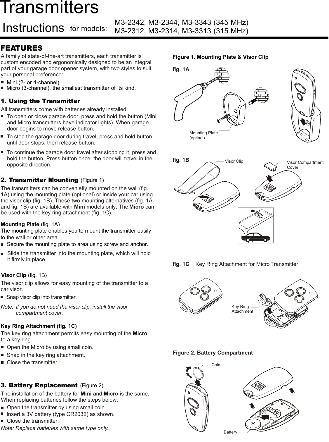
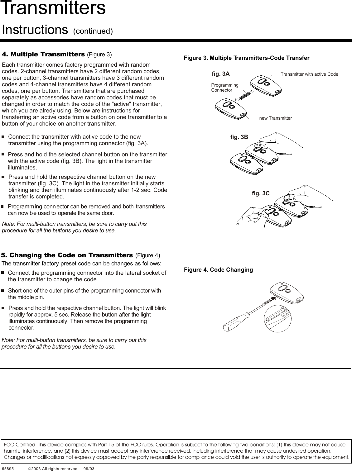
Users Manual
Navigation menu
Upload a User Manual
Namespaces
Wiki Guide
HTML
PDF
Info
Views
User Manual
Discussion / Help
Navigation