Marantec America D384916 Digital 384_ 4-channel and Digital 382_ 2-channel hand transmitter as accessory for garage door opener User Manual 15 Digital 384 382 UserMan
Marantec America Corporation Digital 384_ 4-channel and Digital 382_ 2-channel hand transmitter as accessory for garage door opener 15 Digital 384 382 UserMan
15_Digital 384_382 UserMan
TRANSMITTERS
Instruction for models 315 MHz: Digital 382, Digital 384
916 MHz: Digital 382, Digital 384
FEATURES
A family of state-of-the-art transmitters, each transmitter is custom
encoded and ergonomically designed to be an integral part of your
garage door opener system, with two styles to suit your personal
preference:
Mini 2-channel: Digital 382,
Mini 4-channel: Digital 384.
1. USING THE TRANSMITTER
All transmitters come with batteries already installed.
To open or close garage door, press and hold the button. When
garage door begins to move release button.
To stop the garage door during travel, press and hold button until
door stops, then release button.
To continue the garage door travel after stopping it, press and
hold the button. Press button once, the door will travel in the
opposite direction.
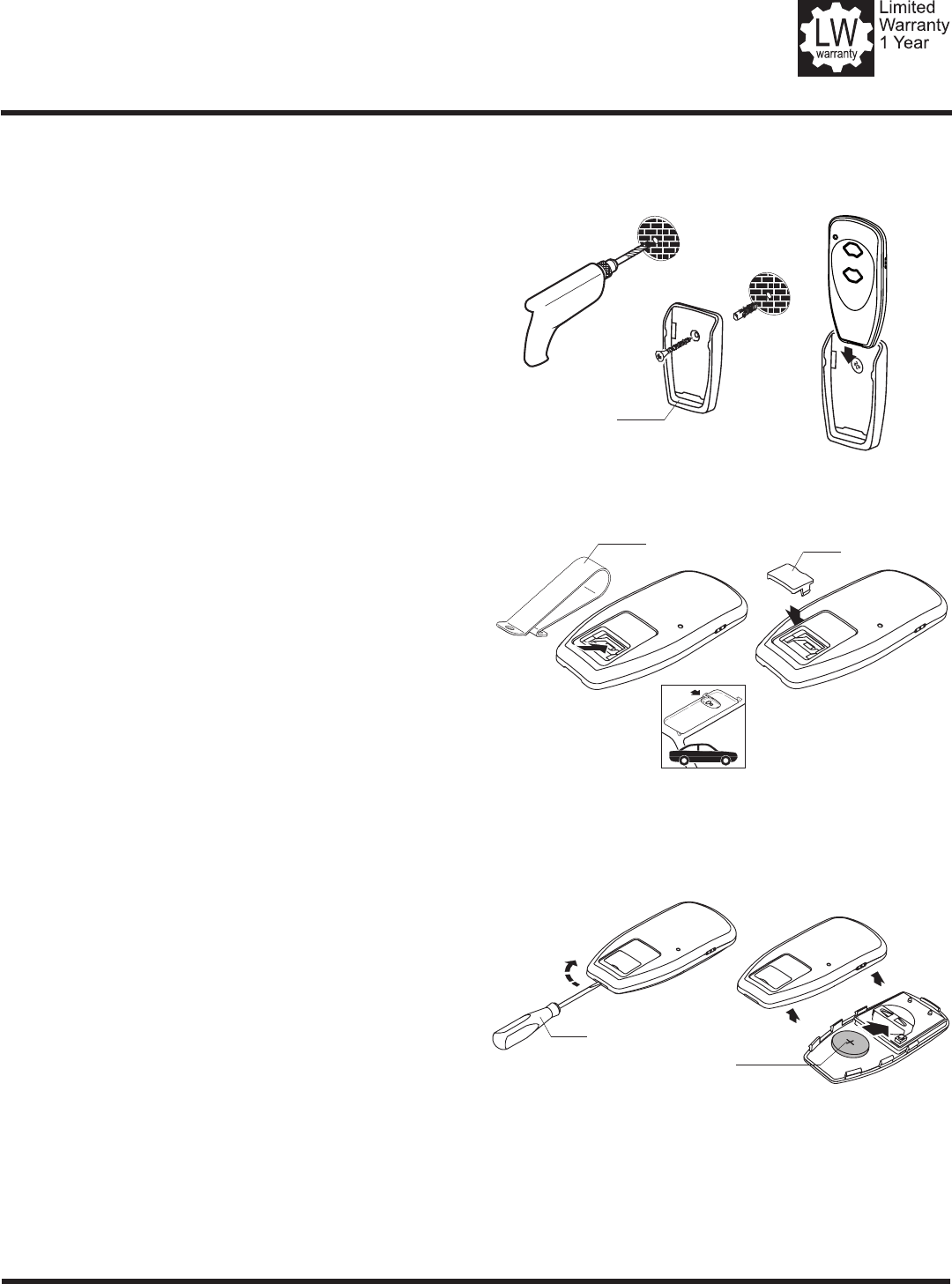
2. TRANSMITTER MOUNTING (Figure 1)
The transmitters can be convenietly mounted on the wall (g. 1A)
using the mounting plate (optional) or inside your car using the visor
clip (g. 1B).
Mounting Plate (g. 1A)
The mounting plate enables you to mount the transmitter easily to
the wall or other area.
Secure the mounting plate to area using screw and anchor.
Slide the transmitter into the mounting plate, which will hold it
rmly in place.
Visor Clip (g. 1B)
The visor clip allows for easy mounting of the transmitter to a car
visor.
Snap visor clip into transmitter.
Note: If you do not need the visor clip, install the visor
compartment cover.
3. BATTERY REPLACEMENT (Figure 2)
The transmitter has a battery check function, which checks the ca-
pacity of the battery during the transmission process. If the battery is
weak, the LED blinks during transmission.
When replacing batteries follow the steps below:
Open the transmitter by using a narrow screwdriver.
Insert a 3V battery (type CR2032) as shown.
Close the transmitter.
Note: Replace batteries with same type only.
Figure 1: Mounting Plate & Visor Clip
Figure 2: Battery Compartment
g. 1A
g. 1B
Mounting Plate
(optional)
Visor Compartment
Cover
Battery
Visor Clip
Screwdriver
FCC Certied: This device complies with Part 15 of the FCC rules. Operation is subject to the following two conditions: (1) this device may
not cause harmful interference, and (2) this device must accept any interference received, including interference that may cause undesired
operation.
FCC §15.21 (Warning Statement): Any changes or modications not expressly approved by the party responsible for compliance could void
the user´s authority to operate the equipment.
CNR Certied: This device complies with Industry Canada licence-exempt RSS standard(s). Operation is subject to the following two condi-
tions:(1) this device may not cause interference, and (2) this device must accept any interference, including interference that may cause
undesired operation of the device.
Le présent appareil est conforme aux CNR d'Industrie Canada applicables aux appareils radio exempts de licence. L'exploitation est autorisée
aux deux conditions suivantes : (1) l'appareil ne doit pas produire de brouillage, et (2) l'utilisateur de l'appareil doit accepter tout brouillage
radioélectrique subi, même si le brouillage est susceptible d'en compromettre le fonctionnement.
TRANSMITTERS
Instruction (continued)
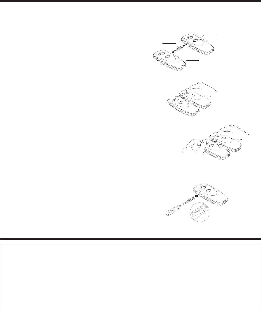
4. MULTIPLE TRANSMITTERS (Figure 3)
Each transmitter comes factory programmed with random codes.
2-channel transmitters have 2 different random codes, one per button
and 4-channel transmitters have 4 different random codes, one per
button. Transmitters that are purchased separately as accessories have
random codes that must be changed in order to match the code of the
“active” transmitter, which you are already using. Below are instruc-
tions for transferring an active code from a button on one transmitter
to a button of your choice on another transmitter.
Connect the transmitter with active code to the new transmitter
using the programming connector (g. 3A).
Press and hold the selected channel button on the transmitter with
the active code (g. 3B). The light in the transmitter illuminates.
Press and hold the respective channel button on the new trans-
mitter (g. 3C). The light in the transmitter initially starts blinking
and then illuminates continuously after 1-2 sec. Code transfer is
completed.
Programming connector can be removed and both transmitters
can now be used to operate the same door.
Note: For multi-button transmitters, be sure to carry out this proce-
dure for all the buttons you desire to use.
5. CHANGING THE CODE ON TRANSMITTERS (Figure 4)
The transmitter factory preset code can be changed as follows:
Connect the programming connector into the lateral socket of the
transmitter to change the code.
Short one of the outer pins of the programming connector with
the middle pin
Press and hold the respective channel button. The light will blink
rapidly for approx. 5 sec. Release the button after the light illu-
minates continuously. Then remove the programming connector.
Note: For multi-button transmitters, be sure to carry out this proce-
dure for all the buttons you desire to use.
Figure 3: Multiple Transmitters-Code Transfer
Figure 4: Code Changing
g. 3A
Transmitter with active Code
Programming
Connector
new Transmitter
g. 3B
g. 3C
UM123406 ©2016 All rights reserved. 6/16 ENG