Marantz Mv8300 Users Manual
MV8300 to the manual 070a31c6-fc0c-4e69-beec-0e02ea0c9977
2015-02-03
: Marantz Marantz-Mv8300-Users-Manual-466650 marantz-mv8300-users-manual-466650 marantz pdf
Open the PDF directly: View PDF ![]() .
.
Page Count: 88
Model MV8300 User Guide
D-VHS Digital Recorder
R
MTP
NTSC
MV8300_U1B-EN01-09 4/1/3, 3:02 PM1
2 EN
Dear Customer,
Thank you for purchasing the Marantz D-VHS video cassette recorder. Before use, please read the safety information and
precautions contained in the following pages to ensure safe use of your new VCR.
CAUTIONS
WARNING:
TO PREVENT FIRE OR SHOCK
HAZARD, DO NOT EXPOSE THIS
UNIT TO RAIN OR MOISTURE.
CAUTION:
This video cassette recorder should be used with AC
120V`, 60Hz only.
To prevent electric shocks and fire hazards, DO NOT use
any other power source.
CAUTION:
TO PREVENT ELECTRIC SHOCK, MATCH WIDE
BLADE OF PLUG TO WIDE SLOT, FULLY INSERT.
ATTENTION:
POUR ÉVITER LES CHOCS ÉLECTRIQUES, INTRODUIRE
LA LAME LA PLUS LARGE DE LA FICHE DANS LA BORNE
CORRESPONDANTE DE LA PRISE ET POUSSER
JUSQU'AU FOND.
CAUTION
RISK OF ELECTRIC SHOCK
DO NOT OPEN
CAUTION: TO REDUCE THE RISK OF ELECTRIC SHOCK.
DO NOT REMOVE COVER (OR BACK).
NO USER-SERVICEABLE PARTS INSIDE.
REFER SERVICING TO QUALIFIED SERVICE PERSONNEL.
The lightning flash with arrowhead symbol, within an equilateral
triangle, is intended to alert the user to the presence of
uninsulated "dangerous voltage" within the product's enclosure
that may be of sufficient magnitude to constitute a risk of electric
shock to persons.
The exclamation point within an equilateral triangle is intended to
alert the user to the presence of important operating and
maintenance (servicing) instructions in the literature
accompanying the appliance.
Note to CATV system installer:
This reminder is provided to call the CATV system
installer’s attention to Article 820-40 of the NEC that
provides guidelines for proper grounding and, in particular,
specifies that the cable ground shall be connected to the
grounding system of the building, as close to the point of
cable entry as practical.
Cassettes marked "D-VHS", "S-VHS" and "VHS" can be used
with this video cassette recorder. However, D-VHS recordings
are possible only with cassettes marked "D-VHS".
By using S-VHS ET it is possible to record and play back with
S-VHS picture quality on VHS cassettes with this VCR.
D-VHS is a new digital memory system that uses D-VHS
tapes. D-VHS was developed as a memory system for
multimedia applications that require storage for large
volumes of information, such as for digital video.
Manufactured under license from Dolby Laboratories.
"Dolby", "Pro Logic", and the double-D symbol are
trademarks of Dolby Laboratories. Confidential unpublished
works. Copyright 1992-1997 Dolby Laboratories. All rights
reserved.
NOTE:
Change or modifications not approved by the party
responsible for compliance could void the user's authority
to operate the equipment.
This equipment has been tested and found to comply with
the limits for a Class B digital device, pursuant to Part 15 of
the FCC Rules. These limits are designed to provide
reasonable protection against harmful interference in a
residential installation. This equipment generates, uses,
and can radiate radio frequency energy and, if not installed
and used in accordance with the instructions, may cause
harmful interference to radio communications. However,
there is no guarantee that interference will not occur in a
particular installation. If this equipment does cause
harmful interference to radio or television reception, which
can be determined by turning the equipment off and on,
the user is encouraged to try to correct the interference by
one or more of the following measures:
Reorient or relocate the receiving antenna.
Increase the separation between the equipment and
receiver.
Connect the equipment into an outlet on a circuit
different from that to which the receiver is connected.
Consult the dealer or an experienced radio/TV
technician for help.
When the equipment is installed in a cabinet or a shelf, make
sure that it has sufficient space on all sides to allow for ventilation
(10 cm or more on both sides, on top and at the rear.)
When discarding batteries, environmental problems must be
considered and the local rules or laws governing the disposal of
these batteries must be followed strictly.
VCR Plus+, C3 and PlusCode are registered trademarks of
Gemstar Development Corporation.
The VCR Plus+ system is manufactured under license from
Gemstar Development Corporation.
DSSTM is an official trademark of DIRECTV, Inc., a unit of GM
Hughes Electronics. DISH NetworkTM is a trademark of Echostar
Communications Corporation.
D-Theater is a technical specification based on D-VHS
standards that was developed for HD content. Commercial
D-Theater titles can only be played back on D-VHS digital
recorders bearing the D-Theater logo.
MTP
NTSC
MV8300_U1B-EN01-09 4/1/3, 3:02 PM2

EN 3
IMPORTANT PRODUCT
SAFETY INSTRUCTIONS
Electrical energy can perform many useful functions. But
improper use can result in potential electrical shock or fire
hazards. This product has been engineered and manufactured
to assure your personal safety. In order not to defeat the built-in
safeguards, observe the following basic rules for its installation,
use and servicing.
ATTENTION:
Follow and obey all warnings and instructions marked on your
product and its operating instructions. For your safety, please
read all the safety and operating instructions before you operate
this product and keep this booklet for future reference.
INSTALLATION
1. Grounding or Polarization
(A) Your product may be equipped with a polarized alternating-
current line plug (a plug having one blade wider than the
other). This plug will fit into the power outlet only one way.
This is a safety feature.
If you are unable to insert the plug fully into the outlet, try
reversing the plug. If the plug should still fail to fit, contact
your electrician to replace your obsolete outlet. Do not
defeat the safety purpose of the polarized plug.
(B) Your product may be equipped with a 3-wire grounding-type
plug, a plug having a third (grounding) pin. This plug will
only fit into a grounding-type power outlet. This is a safety
feature.
If you are unable to insert the plug into the outlet, contact
your electrician to replace your obsolete outlet. Do not
defeat the safety purpose of the grounding-type plug.
2. Power Sources
Operate your product only from the type of power source
indicated on the marking label. If you are not sure of the type of
power supply to your home, consult your product dealer or
local power company. If your product is intended to operate
from battery power, or other sources, refer to the operating
instructions.
3. Overloading
Do not overload wall outlets, extension cords, or integral
convenience receptacles as this can result in a risk of fire or
electric shock.
4. Power Cord Protection
Power supply cords should be routed so that they are not likely
to be walked on or pinched by items placed upon or against
them, paying particular attention to cords at plugs, convenience
receptacles, and the point where they exit from the product.
5. Ventilation
Slots and openings in the cabinet are provided for ventilation.
To ensure reliable operation of the product and to protect it
from overheating, these openings must not be blocked or
covered.
• Do not block the openings by placing the product on a bed,
sofa, rug or other similar surface.
• Do not place the product in a built-in installation such as a
bookcase or rack unless proper ventilation is provided or the
manufacturer’s instructions have been adhered to.
6. Wall or Ceiling Mounting
The product should be mounted to a wall or ceiling only as
recommended by the manufacturer.
ANTENNA
LEAD IN WIRE
ANTENNA
DISCHARGE UNIT
(NEC SECTION
810-20)
GROUNDING
CONDUCTORS
(NEC SECTION 810-21)
GROUND CLAMPS
POWER SERVICE GROUNDING ELECTRODE SYSTEM
(NEC ART 250. PART H)
NEC – NATIONAL ELECTRICAL CODE
ELECTRIC SERVICE
EQUIPMENT
EXAMPLE OF ANTENNA GROUNDING AS PER
NATIONAL ELECTRICAL CODE, ANSI/NFPA 70
GROUND CLAMP
ANTENNA INSTALLATION
INSTRUCTIONS
1. Outdoor Antenna Grounding
If an outside antenna or cable system is connected to the
product, be sure the antenna or cable system is grounded so as
to provide some protection against voltage surges and built-up
static charges. Article 810 of the National Electrical Code,
ANSI/NFPA 70, provides information with regard to proper
grounding of the mast and supporting structure, grounding of
the lead-in wire to an antenna discharge unit, size of grounding
connectors, location of antenna discharge unit, connection to
grounding electrodes, and requirements for the grounding
electrode.
2. Lightning
For added protection for this product during a lightning storm,
or when it is left unattended and unused for long periods of
time, unplug it from the wall outlet and disconnect the antenna
or cable system. This will prevent damage to the product due to
lightning and power-line surges.
3. Power Lines
An outside antenna system should not be located in the vicinity
of overhead power lines or other electric light or power circuits,
or where it can fall into such power lines or circuits. When
installing an outside antenna system, extreme care should be
taken to keep from touching such power lines or circuits as
contact with them might be fatal.
MV8300_U1B-EN01-09 4/1/3, 3:02 PM3

4 EN
SERVICING
1. Servicing
If your product is not operating correctly or exhibits a marked
change in performance and you are unable to restore normal
operation by following the detailed procedure in its operating
instructions, do not attempt to service it yourself as opening or
removing covers may expose you to dangerous voltage or other
hazards. Refer all servicing to qualified service personnel.
2. Damage Requiring Service
Unplug this product from the wall outlet and refer servicing to
qualified service personnel under the following conditions:
a.When the power supply cord or plug is damaged.
b.If liquid has been spilled, or objects have fallen into the
product.
c.If the product has been exposed to rain or water.
d.If the product does not operate normally by following the
operating instructions. Adjust only those controls that are
covered by the operating instructions as an improper
adjustment of other controls may result in damage and will
often require extensive work by a qualified technician to
restore the product to its normal operation.
e.If the product has been dropped or damaged in any way.
f. When the product exhibits a distinct change in
performance—this indicates a need for service.
3. Replacement Parts
When replacement parts are required, be sure the service
technician has used replacement parts specified by the
manufacturer or which have the same characteristics as the
original part. Unauthorized substitutions may result in fire,
electric shock or other hazards.
4. Safety Check
Upon completion of any service or repairs to this product, ask
the service technician to perform safety checks to determine
that the product is in safe operating condition.
HOW TO USE THIS INSTRUCTION
MANUAL
●The Index on pages 79 – 86 lists frequently-used terms, and
the number of the page on which they are used or explained
in the manual. This section also illustrates the controls and
connections on the front and rear panel, the front display
panel and the Remote.
●The mark signals a reference to another page for
instructions or related information.
●Operation buttons necessary for the various procedures are
clearly indicated through the use of illustrations at the
beginning of each major section.
BEFORE YOU INSTALL YOUR NEW
VCR . . .
. . . please read the sections/literature listed below.
●“CAUTIONS” on page 2.
●“IMPORTANT PRODUCT SAFETY INSTRUCTIONS” on the
previous page.
USE
1. Accessories
To avoid personal injury:
• Do not place this product on an unstable cart, stand, tripod,
bracket, or table. It may fall, causing serious injury to a child
or adult, and serious damage to the product.
• Use only with a cart, stand, tripod, bracket, or table
recommended by the manufacturer or sold with the product.
• Use a mounting accessory recommended by the
manufacturer and follow the manufacturer’s instructions for
any mounting of the product.
• Do not try to roll a cart with small casters across thresholds or
deep-pile carpets.
2. Product and Cart Combination
A product and cart combination should
be moved with care. Quick stops,
excessive force, and uneven surfaces
may cause the product and cart
combination to overturn.
3. Water and Moisture
Do not use this product near water—for example, near a bath
tub, wash bowl, kitchen sink or laundry tub, in a wet basement,
or near a swimming pool and the like.
4. Object and Liquid Entry
Never push objects of any kind into this product through
openings as they may touch dangerous voltage points or short-
out parts that could result in a fire or electric shock. Never spill
liquid of any kind on the product.
5. Attachments
Do not use attachments not recommended by the manufacturer
of this product as they may cause hazards.
6. Cleaning
Unplug this product from the wall outlet before cleaning. Do
not use liquid cleaners or aerosol cleaners. Use a damp cloth
for cleaning.
7. Heat
The product should be situated away from heat sources such as
radiators, heat registers, stoves, or other products (including
amplifiers) that produce heat.
PORTABLE CART WARNING
(Symbol provided by RETAC)
MV8300_U1B-EN01-09 4/1/3, 3:02 PM4
EN 5
Failure to heed the following precautions may result in damage to the VCR, Remote or video cassette.
1. DO NOT place the VCR…
… in an environment prone to extreme temperatures or humidity.
… in direct sunlight.
… in a dusty environment.
… in an environment where strong magnetic fields are generated.
… on a surface that is unstable or subject to vibration.
2. DO NOT block the VCR’s ventilation openings or holes.
(If the ventilation openings or holes are blocked by a newspaper or cloth, etc., the heat may not be able to get out.)
3. DO NOT place heavy objects on the VCR or Remote.
4. DO NOT place anything which might spill on top of the VCR or Remote.
(If water or liquid is allowed to enter this equipment, fire or electric shock may be caused.)
5. DO NOT expose the apparatus to dripping or splashing.
6. DO NOT use this equipment in a bathroom or places with water. Also DO NOT place any containers filled with water or liquids
(such as cosmetics or medicines, flower vases, potted plants, cups, etc.) on top of this unit.
7. DO NOT place any naked flame sources, such as lighted candles, on the apparatus.
8. AVOID violent shocks to the VCR during transport.
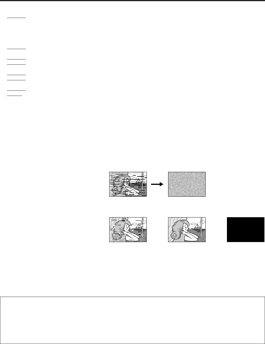
ABOUT HEAD CLEANING
After an extended period of use, the video heads can become dirty, resulting in a loss of picture or sound during
playback. If this happens, clean the video heads by using the optional cleaning tapes.
The heads get dirty in the following cases:
● in an environment prone to extreme
temperature or humidity
● in a dusty environment
● flaw, dirt or mold on video tapes
● continuous usage for a long time
Symptoms of dirty video heads:
●The picture is not clear, or does not appear.
There is no sound.
●Mosaic (block) noise appears in the picture.
●Black or mosaic horizontal stripes appear in the
picture.
●The picture stops (as if the tape is paused).
●A blank black or blue screen appears.
●The picture is fuzzy. (VHS playback)
Use a cleaning tape designed specifically for D-VHS video heads (JVC D-VHS video head cleaner DFC-2) to clean the video heads.
●In order to avoid misoperation, set "NAVIGATION" to "OFF" ( pg. 43).
●Follow the instructions that are provided with the cleaning tape.
If you still do not get a clear picture after using a cleaning tape:
●The heads may be worn. Contact your nearest JVC dealer.
●During VHS playback, if there is a tracking problem, the picture may appear fuzzy. Adjust the tracking manually ( pg. 23).
ATTENTION:
To mobile phone users:
Using a mobile phone in the vicinity of the VCR may cause picture vibration on the TV screen or change the screen to a blue
back display.
On placing the VCR:
Some TVs or other appliances generates strong magnetic fields. Do not place such appliance on top of the VCR as it may cause
picture disturbance.
VHS playback
Early symptom Late symptom
D-VHS playback
Block noise Still image Black screen
MV8300_U1B-EN01-09 4/1/3, 3:02 PM5

6 EN CONTENTS
TIMER RECORDING 34
VCR Plus+® Timer Programing ..................... 34
Changing VCR Plus+ Setting ........................ 36
Express Timer Programing .......................... 38
Checking program settings .......................................40
Canceling or changing program settings ..................40
VIDEO NAVIGATION 42
Navigation Playback .................................. 42
Deactivating Video Navigation ................................43
Finding Tapes ............................................. 44
Finding by tape number ...........................................44
Finding by program title...........................................45
Finding by category .................................................45
Finding by recording date ........................................46
Finding blank space .................................................47
Editing Titles ............................................... 48
Editing tape title .......................................................48
Entering or Editing program title...............................50
Editing program category .........................................50
Deleting tape information ........................................51
Deleting program information..................................52
Checking memory ...................................................52
OTHER USEFUL FUNCTIONS 53
Useful Function Settings .............................. 53
i.LINK Set Up .............................................. 60
Satellite Auto Recording .............................. 62
JLIP ID Number Setting ............................... 63
EDITING 64
i.LINK/DV Connections ................................ 64
S-VIDEO/VIDEO Connections ....................... 66
MULTI-BRAND REMOTE CONTROL 68
TV Brand Setting ......................................... 68
Cable Box Brand Setting ............................. 69
DBS Receiver Brand Setting ......................... 70
Changing Remote Control Code ................... 71
TROUBLESHOOTING 72
Error Codes and Messages .......................................78
Questions and answers ............................................79
INDEX 80
Glossary ..................................................................80
List of terms .............................................................81
Front panel ..............................................................82
Rear panel ...............................................................83
Front display panel ..................................................84
On-screen display....................................................85
Remote ....................................................................86
SPECIFICATIONS 87
FOR SERVICING (Only in U.S.A.) 88
WARRANTY (Only in U.S.A.) 89
INSTALLING YOUR NEW VCR 7
Connections .................................................. 7
INITIAL SETTINGS 9
Plug & Play Setting ....................................... 9
Auto Clock Set/Auto Tuner Set ...................................9
Clock Setting............................................... 10
Preparations.............................................................10
Setting clock semiautomatically
— Semiauto Clock Set .......................................... 11
Setting clock manually — Manual Clock Set ...........12
Tuner Setting .............................................. 13
Setting channels automatically
— Auto Channel Set .............................................13
Setting channels manually
— Manual Channel Set ........................................14
Cable Box Control Setting ........................... 15
Installing Controller .................................................15
Setting cable box input channel & brand .................16
DBS Receiver Control Setting ....................... 18
Installing Controller .................................................18
Setting DBS receiver input channel & brand ............19
BASIC PLAYBACK AND RECORDING 21
Basic Playback ........................................... 21
Basic Playback Features ............................. 22
Checking tape position ............................................22
Playing back tape repeatedly — Repeat Playback ....22
Adjusting tracking condition
— Tracking Adjustments .......................................23
Selecting monitor sound — Audio Monitor ..............23
Automatic operations after rewinding
— Next Function Memory ....................................24
Locating beginning of recordings — Index Search ...24
Skipping unwanted portions — Skip Search .............24
Basic Recording .......................................... 26
D-VHS Recording ....................................................26
S-VHS/VHS Recording .............................................27
Basic Recording Features ............................ 28
Changing display information ..................................28
Specifying recording length
— Instant Timer Recording (ITR) ...........................28
Watching one program while recording another ......29
Showing on-screen display ......................................29
SPECIAL EFFECT PLAYBACK 31
Special Effect Playback ............................... 31
Locating particular scene rapidly
— Picture Search..................................................31
7 High-Speed Picture Search ...............................31
7 Variable-Speed Picture Search ..........................31
Viewing still picture — Still Picture Playback ...........32
Viewing still picture frame by frame
— Frame-by-Frame Playback ...............................32
Viewing slow motion picture
— Slow Motion Playback .....................................33
MV8300_U1B-EN01-09 4/1/3, 3:02 PM6
EN 7
S400
DV IN
D THEATER
REGION 1
i.LINK IN/OUT
DIGITAL OUT
OPTICAL
PCM/DOLBY DIGITAL
R
Y
L
P
B
/C
B
VIDEO
P
R
/C
R
S VIDEO S VIDEO
AUDIO
IN
(L-1)
IN
(L-2)
REMOTE PAUSE/
AV COMPULINK
CABLE BOX
ANTENNA
ANTENNA
OUT
IN
VHF/UHF
RL
VIDEO
AUDIO
OUT IN
COMPONENT
VIDEO OUT
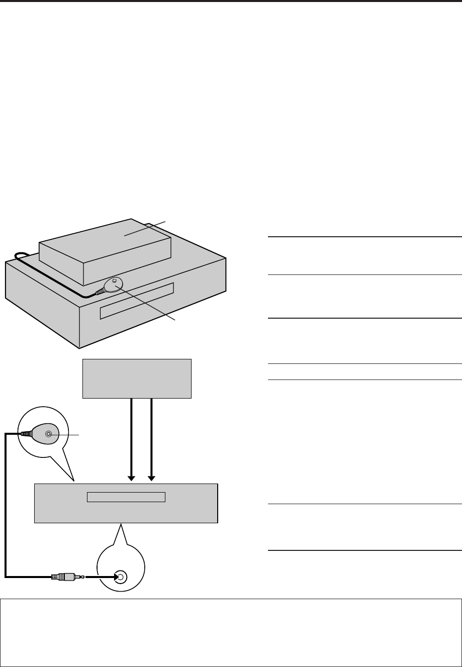
INSTALLING YOUR NEW VCR
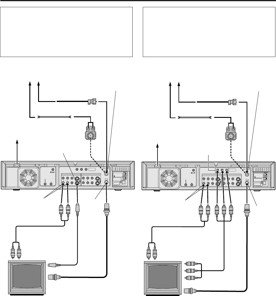
Connections Basic Connection
1Check contents
Make sure the package contains all of the
accessories listed in “SPECIFICATIONS”
( pg. 87).
2Situate VCR
Place the VCR on a stable, horizontal surface.
3Connect VCR to TV
The following connections are required.
1Disconnect the TV antenna from the TV.
2Connect the TV antenna cable to the
ANTENNA IN terminal on the rear of the VCR.
3Connect the supplied RF cable between the
ANTENNA OUT terminal on the rear of the
VCR and the TV’s antenna input terminal.
4Connect an audio/video cable between the
AUDIO/VIDEO OUT connectors on the rear of
the VCR and the audio/video input connectors
on the TV.
S-VIDEO Connection
●
If you have a TV with S-VIDEO input terminals, see
“S-VIDEO Connection” on page 8.
Component Video Connection
●
If you have a TV with component video input
terminals, see “Component Video Connection” on
page 8.
4Connect VCR to power source
Connect the AC power plug to the AC outlet.
●The clock and tuner channels will automatically
be set when the antenna is connected and when
the AC power cord is first connected to an AC
power outlet ( pg. 9).
(If “Auto” or channel numbers are displayed on the
front display panel before the VCR is turned on, the
clock and tuner channels are being set automatically.
Wait until the clock time is displayed on the front
display panel before turning on the VCR.)
5Final preparation for use
Turn on the VCR.
●You can now perform basic playback
( pg. 21) or basic recording ( pg. 26).
NOTES:
●
Your TV must have audio/video input connector for the
connection to the VCR.
●
Even if you are using audio/video cables to connect your VCR
to your TV, you must also connect it using the RF cable. This
will ensure that you can record one show while watching
another (
pg. 29).
●
For full identification of the VCR’s rear panel, refer to the
Index (
pg. 83).
●
If you cannot see the pictures on the TV screen when you
play back a tape, set “TV OUTPUT 1” to the appropriate
mode (
pg. 56).
Matching
Transformer
(not supplied)
AC Power
Cord
Audio Cable
(supplied)
TV
ANTENNA IN
(Antenna or cable input)
Back of VCR
AC Outlet
Antenna or Cable
Flat Feeder
Coaxial Cable
AUDIO OUT
To Audio
Input
Connectors
RF Cable
(supplied)
To 75 Ω terminal
ANTENNA
OUT
Video Cable
(not
supplied)
To Video
Input
Connectors
VIDEO OUT
MV8300_U1B-EN01-09 4/1/3, 3:02 PM7
8 EN
S400
DV IN
D THEATER
REGION 1
i.LINK IN/OUT
DIGITAL OUT
OPTICAL
PCM/DOLBY DIGITAL
R
Y
L
P
B
/C
B
VIDEO
P
R
/C
R
S VIDEO S VIDEO
AUDIO
IN
(L-1)
IN
(L-2)
REMOTE PAUSE/
AV COMPULINK
CABLE BOX
ANTENNA
ANTENNA
OUT
IN
VHF/UHF
RL
VIDEO
AUDIO
OUT IN
COMPONENT
VIDEO OUT
NOTES:
●
To make the most of the Super VHS picture performance we
recommend that you use the supplied S-VIDEO cable to
connect your VCR to a TV with an S-VIDEO input connector.
●
To operate the VCR with your TV using the S-VIDEO
connection, set your TV to the AV mode using the TV's
Remote.
You can also use the TV/VCR button on the VCR’s Remote to
set your TV to the AV mode (
pg. 68).
●
If you cannot see the pictures on the TV screen when you
play back a tape, set “TV OUTPUT 1” to the appropriate
mode (
pg. 56).
S-VIDEO Connection
CONNECT VCR TO TV
a– Connect both the RF cable and the AV cables to the TV as
explained in step 3 of “Basic Connection” ( pg. 7).
b– Connect the S-Video cable between the S VIDEO OUT
terminal on the rear of the VCR and the S-VIDEO input
connector on the TV.
Component Video Connection
CONNECT VCR TO TV
a– Connect both the RF cable and the AV cables to the TV as
explained in step 3 of “Basic Connection” ( pg. 7).
b– Connect the component video cable between the
Component video output terminals on the rear of the VCR
and the component video input terminals on the TV.
NOTES:
●
To change the settings or set the timer program on the menu
screen, switch the TV’s input mode for the connection with
Audio cable.
●
To view the picture of 480i image format on the TV, or to
select and view TV broadcast, connect the component video
cable to the TV’s Y/CB/CR connectors. If your TV has only the
Y/PB/PR connectors, connect also the S-VIDEO or VIDEO
connectors between the VCR and TV.
S400
DV IN
D THEATER
REGION 1
i.LINK IN/OUT
DIGITAL OUT
OPTICAL
PCM/DOLBY DIGITAL
R
Y
L
P
B
/C
B
VIDEO
P
R
/C
R
S VIDEO S VIDEO
AUDIO
IN
(L-1)
IN
(L-2)
REMOTE PAUSE/
AV COMPULINK
CABLE BOX
ANTENNA
ANTENNA
OUT
IN
VHF/UHF
RL
VIDEO
AUDIO
OUT IN
COMPONENT
VIDEO OUT
INSTALLING YOUR NEW VCR (cont.)
Antenna or Cable
Flat Feeder
Coaxial Cable
AC Outlet
TV
Matching
Transformer
(not supplied)
Audio Cable
(supplied)
ANTENNA IN
(Antenna or cable input)
AUDIO
OUT
S VIDEO OUT
AC Power
Cord
Back of VCR
S-Video Cable
(supplied)
RF Cable (supplied)
S-VIDEO IN
Antenna or Cable
Flat Feeder
Coaxial Cable
AC Outlet
TV
Audio Cable
(supplied)
Component
Video Output
AUDIO
OUT
AC Power
Cord
Back of VCR
Component
Video Cable
(not supplied)
RF Cable (supplied)
ANTENNA IN
(Antenna or cable input)
Matching
Transformer
(not supplied)
ANTENNA
OUT ANTENNA
OUT
MV8300_U1B-EN01-09 4/1/3, 3:02 PM8
EN 9
INFORMATION
●If “AUTO CLOCK” is set to “ON” on the Clock Set screen on page 11, the clock will be adjusted automatically by the host
channel every hour (except 11:00 PM, midnight, 1:00 AM and 2:00 AM) using the incoming PBS channel clock setting data.
(This automatic clock adjustment can only be performed when the VCR is turned off. The clock will be adjusted just on these
hours — on the time displayed on the front display panel, not on the actual real time.)
The default setting of “AUTO CLOCK” is “ON”.
●If the memory backup fails, because a power outage occurs or because the AC power cord is unplugged, Auto Clock Set will
be performed when power is restored to the VCR.
●Poor antenna or cable signal may prevent the VCR from receiving the Auto clock setting data from a PBS channel. If this function
is taking a considerable amount of time, it may be necessary to perform the Semiauto or Manual Clock Set procedure ( pg. 12).
What to do if Plug & Play setting failed
●If an incorrect time is displayed on the front display panel, you may be receiving the clock setting data of a PBS channel from
an adjacent time zone, or an incorrect PBS channel from a cable TV system. In this case, perform the Semiauto ( pg. 11) or
Manual Clock Set ( pg. 12) procedure.
●If “– –:– –” appears on the front display panel, your antenna cable may not be connected to the VCR or there may not be a
Host PBS signal available in your area. Ensure that the antenna cable is connected correctly. Then turn on and off the VCR; the
Plug & Play setting will be automatically reactivated.
If Plug & Play setting is not performed though the antenna cable is connected correctly, perform Manual Clock Set ( pg. 12)
and Auto Channel Set or Manual Channel Set ( pg. 13 or 14).
INITIAL SETTINGS
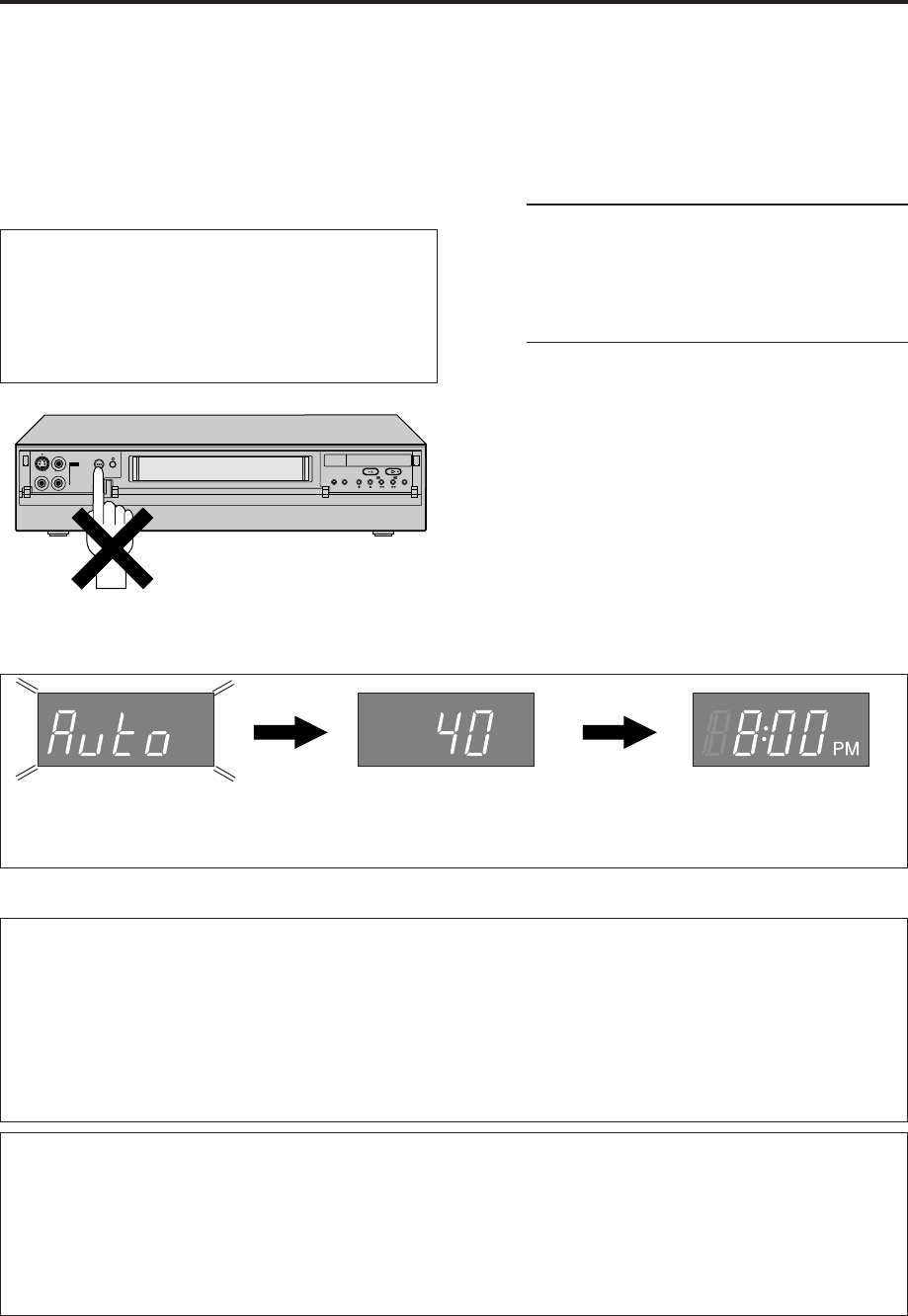
Plug & Play
Setting
This VCR sets the clock and tuner channels
automatically when AC power cord is first connected to
an AC outlet. The antenna cable must be connected for
the Plug & Play setting.
The time and date can be set automatically by the clock
setting data transmitted from one of the regular TV
broadcast channels. We call this TV channel the “host
channel” and it is a PBS channel in your area.
1Perform Plug & Play setup
Connect the antenna cable to the VCR
( pg. 7). Then connect the AC power cord to
an AC outlet. Do not turn on the VCR.
The clock and tuner channels will be set
automatically.
NOTES:
●
When the AC power cord is connected to an AC
outlet, “LOAD” appears on the front display panel. It
takes some time until VCR completes its set up.
●
Auto Clock Set is performed first.
“Auto” blinks on the front display panel during Auto
Clock Set.
●
Auto Channel Set is performed next. Auto Channel Set
scans all the channels that are receivable by your VCR.
During Auto Channel Set, the channel numbers are
displayed as they are scanned and set.
●
When Plug & Play setting has been complete
successfully, the correct clock time is displayed. If you
perform Plug & Play setting successfully, there is no
need to perform the clock (
pg. 10) and tuner (
pg.
13) settings. If, however, you want to add or delete
channels, refer to Manual Channel Set on page 14.
ATTENTION
●If you use a cable box, Plug & Play will not function; set
the clock and tuner channels separately. ( pg.10 – 14)
●It takes several minutes for the VCR to complete the Plug
& Play setting.
●Do not press any buttons on the front panel or on the
Remote while Plug & Play is in progress.
Auto Clock Set/Auto Tuner Set
During Initial Auto Clock Set
“Auto” blinks.
During Auto Channel Set
The channel numbers are displayed
as they are scanned and set.
* If an incorrect clock time or “– –:– –” appears on the display panel, see “What to do if Plug & Play setting failed”
below.
Plug & Play Completed
The current time is
displayed. (“PM” lights up
during the afternoon.)
IN F-1
+
MV8300_U1B-EN01-09 4/1/3, 3:02 PM9
10 EN
Clock Setting Perform clock setting only if the clock has not been set
correctly by the Plug & Play setting or if you use a cable
box.
Access the Clock Set screen to perform the Semiauto or
Manual Clock Set. Each procedure starts from step 3
after preparation steps below are finished.
If you use a cable box, set the clock manually. (墌 pg. 12)
Preparations
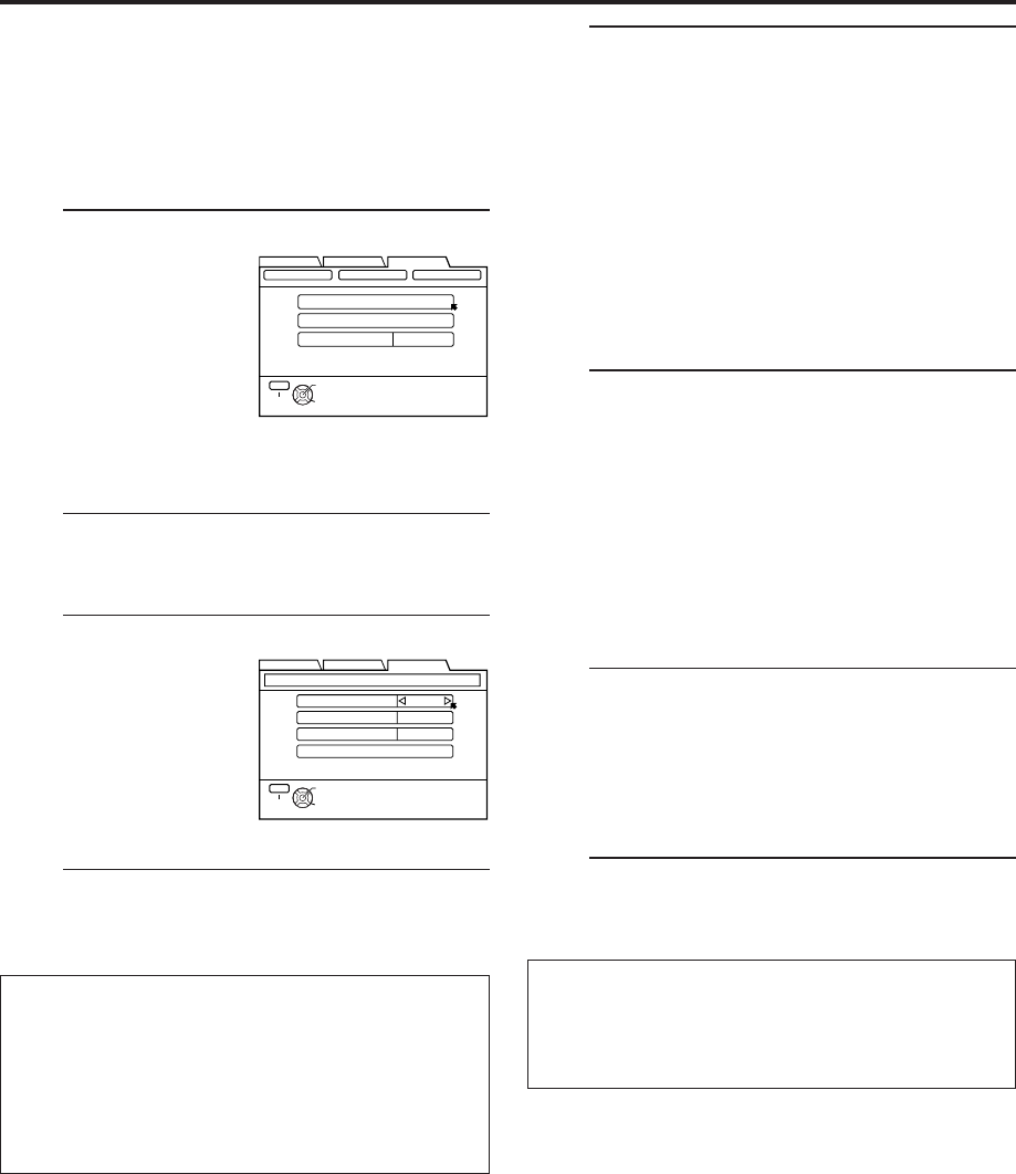
1Access Main Menu screen
Press MENU.
2Access Clock Set screen
1Press
@
#
to move
the arrow to
“INITIAL SET
UP”, then press fi
or OK.
2Press
@
#
to move
the arrow to
“CLOCK SET”,
then press fi or OK.
●If “CABLE BOX USERS SET CLOCK
MANUALLY” appears on the screen, press OK
to access the Clock Set screen. (Even if you do
not press OK, the Clock Set screen disappears
after 5 seconds, then the Clock Set screen
appears automatically).
●Turn on the VCR and the TV, and select the AV
mode on the TV.
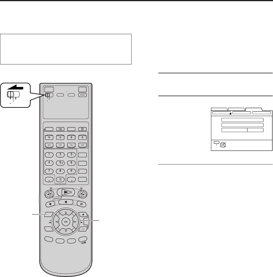
●Set the VCR/TV/CABLE/DBS selector on the
Remote to “VCR”.
VCR
TV
CABLE
/DBS
1 7 2 – 6
INITIAL SETTINGS (cont.)
FUNCTION SET UP
INITIAL SET UPTUNER SET UP
THEN PRESS [OK]
CLOCK SET
AUTO CLOCK SET
MANUAL CLOCK SET
AUTO CLOCK OFF
GUIDE CHANNEL OTHER
SELECT WITH ARROW KEYS
SELECT
OK
EXIT
MENU
MV8300_U1B-EN10-14 4/1/3, 3:59 PM10
EN 11
Setting clock semiautomatically
— Semiauto Clock Set
You can change the host channel/D.S.T. /time zone
setting manually.
First follow steps 1 to 2 on page 10, then go to the
following steps.
3Access Auto Clock Set screen
Press %fi to move
the arrow to “AUTO
CLOCK SET”, then
press OK.
Then;
To select the host channel — go to step 4.
To select the D.S.T. mode — go to step 5.
To select the time zone — go to step 6.
NOTE:
The time set previously will be erased when “AUTO
CLOCK SET” is selected.
4Select host channel
You can either select
“AUTO” or enter a
PBS channel number.
Press %fi to move
the arrow to “HOST
CH”, then press
@ #
until “AUTO” or the
desired PBS channel
number is selected.
NOTE:
Some PBS channels do not transmit clock setting data.
* Auto Daylight Saving Time
This function enables automatic adjustment of the VCR’s
clock at the start and end of Daylight Saving Time.
With Auto DST activated, . . .
. . . on the first Sunday of April at 2:00 AM, the clock is
adjusted to 3:00 AM.
. . . on the last Sunday of October at 2:00 AM, the clock is
adjusted to 1:00 AM.
5Select D.S.T. mode
You have three choices:
AUTO– Select if you want to adjust your VCR’s
clock automatically by the incoming
signal from the host channel. (Auto
Daylight Saving Time*)
ON– Adjustment will be made by the built-in
clock itself.
OFF– Select when Daylight Saving Time does
not apply to you.
Press %fi to move the arrow to “D.S.T.”, then
press
@ #
repeatedly until the desired setting is
selected.
6Select time zone
You can select the time zone automatically or
manually.
Press %fi to move the arrow to “TIME ZONE”,
press
@ #
repeatedly until “AUTO” or the desired
time zone is selected.
Each time you press the button, the time zone
changes as follows:
O AUTO O ATLANTIC O EASTERN
O CENTRAL O MOUNTAIN O PACIFIC
O ALASKA O HAWAII O (back to the beginning)
NOTE:
If an incorrect clock time is displayed by the Plug &
Play setting, you may be receiving the clock setting
data of a PBS channel from an adjacent time zone or
from an incorrect PBS channel from a cable TV system.
If you selected “AUTO” for the host channel in step
4
,
be sure to select the correct time zone manually.
7Return to normal screen
Press MENU.
IMPORTANT
Turn off the VCR after performing Semiauto Clock Set.
“Auto” will appear on the front display panel while the
clock is being set. The current clock time will appear
automatically when the clock setting is complete.
FUNCTION SET UP
INITIAL SET UPTUNER SET UP
THEN PRESS [OK]
CLOCK SET
AUTO CLOCK SET
MANUAL CLOCK SET
AUTO CLOCK ON
GUIDE CHANNEL OTHER
SELECT WITH ARROW KEYS
SELECT
OK
EXIT
MENU
FUNCTION SET UP
INITIAL SET UPTUNER SET UP
THEN PRESS [OK]
HOST CH [TV]
D.S.T AUTO
AUTO
AUTO
TIME ZONE
RETURN
AUTO CLOCK SET TIME – –:– – AM DATE 1/1 (WED) 2003
SELECT WITH ARROW KEYS
SELECT
OK
EXIT
MENU
MV8300_U1B-EN10-14 4/1/3, 3:59 PM11
12 EN
Setting clock manually
— Manual Clock Set
First follow steps 1 to 2 on page 10, then go to the
following steps.
3Access Manual Clock Set screen
Press %fi to move the arrow to “MANUAL
CLOCK SET”, then press OK.
4Set time
Press
@
#
until the
desired time appears,
then press fi.
●Holding
@
#
changes the time in
30-minute intervals.
5Set date
Press
@
#
until the desired date appears, then
press fi.
●Holding
@
#
changes the date in 15-day
intervals.
6Set year
Press
@
#
until the desired year appears.
7Select D.S.T. mode
Press %fi to move the highlight bar to “D.S.T.”,
then press
@
#
to select “ON” or “OFF”.
ON– Adjustment will be made by the built-in
clock itself.
OFF– Select when Daylight Saving Time does
not apply to you.
8Start clock
Press MENU and normal screen appears.
To make corrections any time during the process
Press %fi to select the item you want to change, then
press
@
#
.
VCR
TV
CABLE
/DBS
83 – 7
INITIAL SETTINGS (cont.)
FUNCTION SET UP
INITIAL SET UPTUNER SET UP
THEN PRESS [OK]
TIME – –:– –
1/1 (WED)
2003
D.S.T OFF
YEAR
DATE
RETURN
MANUAL CLOCK SET
SELECT WITH ARROW KEYS
SELECT
OK
EXIT
MENU
MV8300_U1B-EN10-14 4/1/3, 3:59 PM12
EN 13
Tuner Setting Setting channels automatically
— Auto Channel Set
Use Auto Channel Set only if channels have not been set
correctly by the Plug & Play setting. If you want to add
or delete channels, use Manual Channel Set (墌 pg. 14).
1Access Main Menu screen
Press MENU.
2Access Tuner Set Up screen
1Press
@ #
to move
the arrow to
“TUNER SET UP”,
then press fi or
OK.
2Press
@ #
to move
the arrow to
“TUNER SET”,
then press fi or OK.
3Perform Auto Channel Set
You can automatically
set the receivable
channels in your area
in the order of their
frequencies.
Press %fi to move the
arrow to “AUTO CH
SET”, then press OK.
NOTES:
●
When Auto Channel
Set is complete,
“SCAN COMPLETED”
appears on screen.
●
If the scan was
unsuccessful, “SCAN
COMPLETED – NO SIGNAL FOUND –” appears on
screen. Check the connections, then select “RETRY”
to start again, or select “EXIT”.
4Return to normal screen
Press MENU.
INFORMATION
The VCR selects the correct band (TV or CATV)
automatically during Auto Channel Set.
The selected band will be displayed on the right side of
“BAND” on the Tuner Set Up screen.
FUNCTION SET UP
INITIAL SET UPTUNER SET UP
THEN PRESS [OK]
BAND
AUTO CH SET
MANUAL CH SET
TV
DBS SET UP
SELECT WITH ARROW KEYS
SELECT
OK
EXIT
MENU
TUNER SET CABLE SET UP
VCR
TV
CABLE
/DBS
1 4 2 3
FUNCTION SET UP
INITIAL SET UPTUNER SET UP
THEN PRESS [OK]
AUTO CHANNEL SET
SCANNING...
PRESS [MENU] TO END
DBS SET UP
SELECT WITH ARROW KEYS
SELECT
OK
EXIT
MENU
TUNER SET CABLE SET UP
FUNCTION SET UP
INITIAL SET UPTUNER SET UP
THEN PRESS [OK]
TUNER SET
BAND
AUTO CH SET
MANUAL CH SET
TV
CABLE SET UP DBS SET UP
SELECT WITH ARROW KEYS
SELECT
OK
EXIT
MENU
●Turn on the VCR and the TV, and select the AV
mode on the TV.
●Set the VCR/TV/CABLE/DBS selector on the
Remote to “VCR”.
MV8300_U1B-EN10-14 4/1/3, 3:59 PM13
14 EN
3Access Manual Channel Set screen
Press %fi to move
the arrow to
“MANUAL CH SET”,
then press OK.
4Add or skip desired channels
To add channels
1Press %fi to move
the arrow to “CH”,
then press the
Number keys to
input a channel
number you want
to add.
2Press %fi to move the arrow to “ADD/SKIP”,
then press
@
#
to set to “ADD”.
3Repeat 1 and 2 to add other channels.
To skip channels
1Press %fi to move
the arrow to “CH”,
then press the
Number keys or
@#
to input a
channel number
you want to skip.
2Press %fi to move
the arrow to “ADD/SKIP”, then press
@
#
to set
to “SKIP”.
3Repeat 1 and 2 to skip other channels.
5Return to normal screen
Press MENU.
Setting channels manually
— Manual Channel Set
You can add the channels you want or delete the
channels you do not want manually.
1Access Main Menu screen
Press MENU.
2Access Tuner Set Up screen
1Press
@ #
to move the arrow to “TUNER SET
UP”, then press fi or OK.
2Press
@ #
to move the arrow to “TUNER SET”,
then press fi or OK.
INITIAL SETTINGS (cont.)
VCR
TV
CABLE
/DBS
1 5 2 – 4
4
FUNCTION SET UP
INITIAL SET UPTUNER SET UP
THEN PRESS [OK]
BAND
AUTO CH SET
MANUAL CH SET
TV
DBS SET UP
SELECT WITH ARROW KEYS
SELECT
OK
EXIT
MENU
TUNER SET CABLE SET UP
FUNCTION SET UP
INITIAL SET UPTUNER SET UP
OR NUMBER KEYS
CH [TV]
ADD/SKIP ADD
RETURN
45
SELECT WITH ARROW
SELECT
OK
EXIT
MENU
MANUAL CH SET
FUNCTION SET UP
INITIAL SET UPTUNER SET UP
OR NUMBER KEYS
CH [TV]
ADD/SKIP
RETURN
SELECT WITH ARROW
SELECT
OK
EXIT
MENU
MANUAL CH SET
SKIP
46
MV8300_U1B-EN10-14 4/1/3, 3:59 PM14
EN 15
CABLE
BOX
The following procedure is required if you receive your
TV channels through a cable box (descrambler). The
Controller allows the VCR to automatically switch the
cable box channel during timer recording. The
Controller is effective for recording broadcasts that have
been programed using VCR Plus+ (墌 pg. 34) or Express
timer programing (墌 pg. 38).
Installing Controller
1Situate Controller
Place the Controller so that its transmitter is
facing the cable box’s remote sensor.
●Make sure the path between the Controller and
the cable box’s remote sensor is not blocked.
2Attach Controller
Fix securely using the adhesive strip attached on
the back of the Controller.
3Connect cable box to VCR
●
If your cable box does not have audio/video
output connectors
Connect the RF output terminal on the cable
box to the ANTENNA IN terminal on the rear of
your VCR.
●
If your cable box has audio/video output
connectors
Connect an audio/video cable between the
AUDIO/VIDEO IN connectors on the rear of
the VCR and the audio/video output connectors
on the cable box.
NOTE:
When connecting your cable box, refer to its instruction
manual.
4Connect Controller to VCR
Connect the Controller to the CABLE BOX
Controller connector on the rear panel.
Cable Box
Control
Setting
Suggested location
Place the cable box on top of the VCR. Attach the VCR’s
Controller to the top of the VCR with the Controller’s
transmitter pointed towards the cable box’s remote
sensor.
ATTENTION:
The Controller can also control a DBS receiver. If both a cable
box and a DBS receiver are used, position the Controller so its
signal reaches the remote sensors on both the cable box and
DBS receiver.
How to control the cable box
This VCR has two separate methods to control your cable
box.
●The VCR’s wireless Remote can control your cable box.
This eliminates the need for a separate cable box’s
Remote.
●The VCR’s Controller can also control your cable box.
This allows the VCR to change your cable box’s channel
number during timer recording.
Each method must be set up separately. To set up the VCR’s
Remote, refer to page 69. To set up the Controller, go to
page 16.
Cable box
Cable box
Your VCR
Controller
(suggested
locations)
Transmitter
Your VCR
To
ANTENNA
IN
To
AUDIO/
VIDEO IN
To
RF output
To
Audio/video
output
or
Controller
(supplied)
MV8300_U1B-EN15-20 4/1/3, 2:37 PM15
16 EN
Setting cable box input
channel & brand
After installation, set the cable box input channel and its
brand correctly; otherwise, the Controller cannot work
correctly.
1Turn on cable box
Select a channel other than channel 9 on your
cable box.
2Access Main Menu screen on VCR
Press MENU.
3Access Cable Set Up screen
1Press
@ #
to move
the arrow to
“TUNER SET UP”,
then press fi or
OK.
2Press
@ #
to move
the arrow to
“CABLE SET UP”,
then press fi or OK.
4Select cable box input channel
Press %fi to move
the arrow to “INPUT
CH”.
Your selection
depends on how your
cable box is
connected to your
VCR.
●If your cable box is connected to your VCR’s
ANTENNA IN terminal on the rear panel
Press
@
#
until the channel number
representing the cable box’s output (ON CH2 –
ON CH9) appears on the screen.
●If your cable box is connected to your VCR’s
AUDIO/VIDEO IN connectors on the front panel
Press
@
#
until “ON F-1” appears on the
screen.
●If your cable box is connected to your VCR’s
AUDIO/VIDEO IN (L-1) or AUDIO/VIDEO IN
(L-2) connectors on the rear panel
Press
@
#
until “ON L-1” or “ON L-2” appears
on the screen.
●If you do not use a cable box
Press
@
#
until “OFF” appears on the screen.
VCR
TV
CABLE
/DBS
3 – 6
2 7
INITIAL SETTINGS (cont.)
FUNCTION SET UP
INITIAL SET UPTUNER SET UP
THEN PRESS [OK]
DBS SET UP
SELECT WITH ARROW KEYS
SELECT
OK
EXIT
MENU
INPUT CH
BRAND 1
TEST MODE
OFF
TUNER SET CABLE SET UP
FUNCTION SET UP
INITIAL SET UPTUNER SET UP
THEN PRESS [OK]
INPUT CH
BRAND 1
TEST MODE
OFF
SELECT WITH ARROW KEYS
SELECT
OK
EXIT
MENU
CABLE SET UP
●Turn on the VCR and the TV, and select the AV
mode on the TV.
●Set the VCR/TV/CABLE/DBS selector on the
Remote to “VCR”.
MV8300_U1B-EN15-20 4/1/3, 2:37 PM16
EN 17
5Enter cable box brand
Press %fi to move
the arrow to
“BRAND”.
Press
@
#
to enter the
brand code from the
list shown to the
right.
6Engage test mode
Press %fi to move the arrow to “TEST MODE”,
then press OK.
NOTE:
If you do not engage the test mode in step
6
, “INPUT
CH” and “BRAND” are not set.
●If the cable box’s
channel changes
to 9, setting is
complete
Press
@
#
to move
the arrow to
“YES”, then press
OK and “CABLE
BOX CONTROL IS ON” appears on the screen
for about 5 seconds.
●If the cable box’s channel does not change to 9
1Press
@
#
to move the arrow to “NO”.
2Press OK.
3Repeat step 5 until the cable box’s channel
changes to 9 by entering another code.
4If the channel does not change after going
through all the code numbers listed for your
model of cable box, then try all the other
numbers.
7Return to normal screen
Press MENU.
CABLE BOX BRAND LIST
BRAND CODE
ARCHER 1, 5, 17
CABLETENNA 1, 17
CABLEVIEW 15, 16, 17, 21, 25
CITIZEN 15, 16, 17, 21, 25
CURTIS 2, 8
DIAMOND 1, 17
GC BRAND 15, 16, 17, 21, 25
GEMINI 15
GENERAL INSTRUMENTS 1, 4, 6, 11, 12, 15, 28
HAMLIN 10, 18, 23
JASCO 15
JERROLD 1, 4, 6, 11, 12, 15, 28
NOVAVISION 2, 8
OAK 7, 20
PANASONIC 13, 14
PULSER 15, 16, 17, 21, 25
RCA 13, 14
REGAL 10, 18, 23
REMBRANDT 1, 16, 17
SAMSUNG 5, 16, 24
SCIENTIFIC ATLANTA 2, 8
SIGMA 7, 20
SL MARX 5, 16, 17, 24, 25
SPRUCER 13, 14
STARGATE 5, 15, 16, 17, 21, 24, 25
TELEVIEW 5, 16, 24
TOCOM 1, 4, 16
UNIKA 1, 17
UNIVERSAL 16, 17, 25
VIDEOWAY 3, 9, 22
ZENITH 3, 9, 22
If the VCR’s clock has not been set (with AUTO
CLOCK set to ON)
“CABLE BOX USERS SET CLOCK MANUALLY” appears for
about 5 seconds when you press OK in step 3, then the
Clock Set screen appears.
Perform Manual Clock Set on page 12. If you press MENU
after the clock has been set, the Cable Box Input Channel
screen in step 4 appears.
NOTES:
●
The Controller may not work with all types of cable box.
●
If your cable box does not respond to any code, you cannot
use the Controller to change cable box channels. In this case,
make sure to leave the cable box turned on and tuned to the
proper channel before the scheduled start time of timer
recording.
Contact your cable company about the possibility of
exchanging your current cable box with the one compatible
with your VCR.
●
The VCR can only change the cable box channel through the
Controller during timer recording.
●
If your cable box cannot be operated with a Remote (because
it has no remote sensor), you cannot use the Controller to
change its channels. Make sure to leave the cable box turned
on and tuned to the proper channel before the scheduled start
time of timer recording.
●
If the VCR’s memory backup expires because of a power
failure, set the cable box input channel and brand again.
●
For customers in U.S.A.: If you are unable to set the
Controller, contact your Marantz authorized dealer.
FUNCTION SET UP
INITIAL SET UPTUNER SET UP
THEN PRESS [OK]
INPUT CH
BRAND 1
TEST MODE
OFF
SELECT WITH ARROW KEYS
SELECT
OK
EXIT
MENU
CABLE SET UP
INPUT CH
BRAND 1
TEST MODE
OFF
FUNCTION SET UP
INITIAL SET UPTUNER SET UP
THEN PRESS [OK]
SELECT WITH ARROW KEYS
SELECT
OK
EXIT
MENU
CABLE SET UP
YES NO
DID YOUR CABLE BOX CHANGE TO
CHANNEL 09?
MV8300_U1B-EN15-20 4/1/3, 2:37 PM17
18 EN INITIAL SETTINGS (cont.)
The following procedure is required if you receive
satellite channels through a DBS (Direct Broadcast
Satellite) receiver. The Controller allows the VCR to
automatically switch the DBS receiver’s channels during
timer recording.
NOTES:
●
The VCR can automatically change the DBS receiver
channels using the Controller when the VCR has been
programed using Express timer programing (
墌
pg. 38).
Because satellite programing does not use PlusCode, the
Controller cannot change the DBS receiver channels during
VCR Plus+ timer recording.
(You can also use “Satellite Auto Recording” (
墌
pg. 62) if
your DBS receiver is equipped with a timer.)
●
If a cable box is also used, it is recommended that you connect
the DBS receiver to your VCR’s audio/video input connectors
and the cable box to your VCR’s antenna input terminal.
Installing Controller
1Situate Controller
Place the Controller so that its transmitter is
facing the DBS receiver’s remote sensor.
●Make sure the path between the Controller and
the DBS receiver’s remote sensor is not
blocked.
2Attach Controller
Fix securely using the adhesive strip attached on
the back of the Controller.
3Connect DBS receiver to VCR
●
If your DBS receiver does not have audio/
video output connectors
Connect the RF output terminal on the DBS
receiver to the ANTENNA IN terminal on the
rear of your VCR.
●
If your DBS receiver has audio/video output
connectors
Connect an audio/video cable between the
AUDIO/VIDEO IN connectors on the rear of
the VCR and the audio/video output connectors
on the DBS receiver.
NOTE:
When connecting your DBS receiver, refer to its
instruction manual.
4Connect Controller to VCR
Connect the Controller to the CABLE BOX
Controller connector on the rear panel.
DBS Receiver
Control Setting
Suggested location
Place the DBS (Direct Broadcast Satellite) receiver on top
of the VCR. Attach the VCR’s Controller to the top of the
VCR with the Controller’s transmitter pointed towards
the DBS receiver’s remote sensor.
ATTENTION:
The Controller can also control a cable box. If both a DBS
receiver and a cable box are used, position the Controller so its
signal reaches the remote sensors on both the DBS receiver and
cable box.
How to control the DBS receiver
This VCR has two separate methods to control your DBS receiver.
●The VCR’s wireless Remote can control your DBS receiver. This eliminates the need for a separate DBS receiver’s Remote.
●The VCR’s Controller can also control your DBS receiver. This allows the VCR to change your DBS receiver’s channel number
during timer-recording.
Each method must be set up separately. To set up the VCR’s Remote, refer to page 70. To set up the Controller, go to page 19.
CABLE
BOX
DBS receiver
DBS receiver
Your VCR
Controller
(suggested
locations)
Transmitter
Your VCR
To
ANTENNA IN
To
AUDIO/
VIDEO IN
To
RF output To
Audio/Video
output
or
Controller
(supplied)
MV8300_U1B-EN15-20 4/1/3, 2:37 PM18
EN 19
Setting DBS receiver input
channel & brand
After installation, set the DBS receiver’s input channel
and its brand correctly; otherwise, the Controller cannot
work correctly.
1Turn on DBS receiver
Select a channel other than channel 100 or 205
on your DBS receiver.
2Access Main Menu screen on VCR
Press MENU.
3Access DBS Receiver Set screen
1Press
@ #
to move
the arrow to
“TUNER SET UP”,
then press fi or
OK.
2Press
@ #
to move
the arrow to “DBS
SET UP”, then
press fi or OK.
4Select DBS receiver input channel
Press %fi to move
the arrow to
“INPUT CH”.
Your selection
depends on how
your DBS receiver
is connected to
your VCR.
●If your DBS receiver is connected to your
VCR’s ANTENNA IN terminal on the rear
panel
Press
@
#
until the channel number
representing the DBS receiver’s output (ON
CH3 or ON CH4) appears on the screen.
●If your DBS receiver is connected to your VCR’s
AUDIO/VIDEO IN connectors on the front panel
Press
@
#
until “ON F-1” appears on the
screen.
●If your DBS receiver is connected to your VCR’s
AUDIO/VIDEO IN (L-1) or AUDIO/VIDEO IN
(L-2) connectors on the rear panel
Press
@
#
until “ON L-1” or “ON L-2” appears
on the screen.
●If you do not use a DBS receiver
Press
@
#
until “OFF” appears on the screen.
CONTINUED ON NEXT PAGE \
VCR
TV
CABLE
/DBS
23 4
FUNCTION SET UP
INITIAL SET UPTUNER SET UP
THEN PRESS [OK]
DBS SET UP
SELECT WITH ARROW KEYS
SELECT
OK
EXIT
MENU
INPUT CH
BRAND
TEST MODE
OFF
40
TUNER SET CABLE SET UP
FUNCTION SET UP
INITIAL SET UPTUNER SET UP
THEN PRESS [OK]
INPUT CH
BRAND
TEST MODE
OFF
40
SELECT WITH ARROW KEYS
SELECT
OK
EXIT
MENU
DBS SET UP
●Turn on the VCR and the TV, and select the AV
mode on the TV.
●Set the VCR/TV/CABLE/DBS selector on the
Remote to “VCR”.
MV8300_U1B-EN15-20 4/1/3, 2:37 PM19
20 EN
5Enter DBS Receiver’s brand
Press %fi to move
the arrow to
“BRAND”.
Press
@
#
to enter the
brand code from the
following list.
6Engage test mode
Press %fi to move the arrow to “TEST MODE”,
then press OK.
The program currently received through the DBS
receiver appears for about 10 seconds.
NOTE:
If you do not engage the test mode in step
6
, “INPUT
CH” and “BRAND” are not set.
●If the DBS receiver’s channel changes to 205,
setting is complete
Press
@
#
to move
the arrow to “YES”,
then press OK and
“DBS RECEIVER
CONTROL IS ON”
appears on the
screen for about 5
seconds.
●If the DBS receiver’s channel does not change
as shown above
1Press
@
#
to move the arrow to “NO”.
2Press OK.
3Re-enter the correct code.
7Return to normal screen
Press MENU.
INITIAL SETTINGS (cont.)
VCR
TV
CABLE
/DBS
5 6
7
NOTES:
●
The Controller may not work with all types of DBS receiver.
●
If your DBS receiver does not respond to the code, you
cannot use the Controller to change satellite channels. In this
case, make sure to leave the DBS receiver turned on and
tuned to the proper channel before the scheduled start time of
timer recording. In addition, if your DBS receiver is equipped
with a timer, you can also use “Satellite Auto Recording”
(
墌
pg. 62).
●
The VCR can only change the satellite channel through the
Controller during timer recording.
●
If your DBS receiver cannot be operated with a Remote
(because it has no remote sensor), you cannot use the
Controller to change its channels. Make sure to leave the DBS
receiver turned on and tuned to the proper channel before the
scheduled start time of timer recording.
●
For customers in U.S.A.: If you are unable to set the
Controller, contact your Marantz authorized dealer.
FUNCTION SET UP
INITIAL SET UPTUNER SET UP
THEN PRESS [OK]
INPUT CH
BRAND
TEST MODE
OFF
40
SELECT WITH ARROW KEYS
SELECT
OK
EXIT
MENU
DBS SET UP
FUNCTION SET UP
INITIAL SET UPTUNER SET UP
THEN PRESS [OK]
YES NO
DID YOUR DBS RECEIVER CHANGE TO
CHANNEL 205?
SELECT WITH ARROW KEYS
SELECT
OK
EXIT
MENU
DBS SET UP
INPUT CH OFF
BRAND CODE
JVC (DISH Network) 51
ECHOSTAR (DISH Network) 51
SONY (DSS) 41
RCA (DSS) 40
MV8300_U1B-EN15-20 4/1/3, 2:37 PM20
EN 21
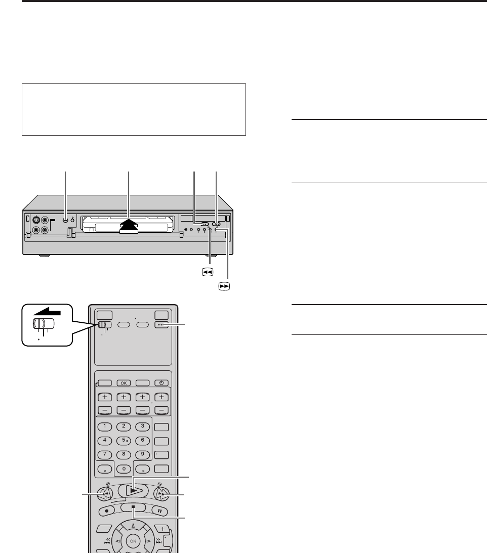
IN F-1
+
POWER STOP/EJECT
(7/0)
1 2
REW ( )
FF ( )
BASIC PLAYBACK AND RECORDING
Basic
Playback
This VCR can check the tape condition during playback
(and recording), and realizes the best possible pictures.
●This VCR can play back tapes that have been recorded
in D-VHS (MTP), S-VHS, S-VHS ET and VHS formats.
●When playing back a tape, this VCR automatically
identifies the recording format (D-VHS, S-VHS, S-VHS
ET or VHS).
●When you play back a tape recorded on this VCR, you
can use the Video Navigation function ( pg. 42).
1Load a cassette
Make sure the window side is up, the rear label
side is facing you and the arrow on the front of
the cassette is pointing towards the VCR.
Do not apply too much pressure when inserting.
●The VCR turns on automatically.
●The tape will run for a few seconds while the
VCR searches for the tape number. If the tape
number is found, it will be shown on the TV
screen if “SUPERIMPOSE” is set to “ON”
( pg. 57).
●The counter is reset automatically, however, it
is not completely reset to “0:00:00”.
●If the cassette’s record safety tab has been
removed, playback begins automatically.
2Start playback
Press PLAY ( 3 ).
●Recording speed is automatically detected.
●If “V. CALIBRATION” is set to “ON” (default
setting) and “PICTURE CONTROL” is set to
“AUTO”: ( pg. 54), “VIDEO CALIBRATION”
appears on the screen, and this VCR checks the
tape condition during automatic tracking (only
cassettes recorded in the S-VHS, S-VHS ET or
VHS mode).
To stop playback
Press STOP ( 7 ) on the Remote or STOP/EJECT ( 7/0 )
on the front panel.
To rewind the tape (when it is not running)
Press REW ( 1 ).
To fast-forward (when it is not running)
Press FF ( ¡ ).
To eject the tape
Press STOP/EJECT ( 7/0 ) on the front panel when the
tape is not running.
● You can also eject the cassette when the VCR is turned
off.
To turn off the VCR
Press POWER.
VCR
TV
CABLE
/DBS
POWER
REW(1)
2
FF(¡)
STOP(7)
●Turn on the VCR and the TV, and select the AV
mode on the TV.
●Set the VCR/TV/CABLE/DBS selector on the
Remote to “VCR”.
NOTES:
●
When you use the Video Navigation function, operate the
VCR only after the tape number is detected; otherwise, you
cannot use the Video Navigation function.
●
It takes a moment until the image appears on the TV screen
when you play back a program recorded in LS5 mode. The
picture may pause or the block noise may appear.
●
It will take a moment until the image appears when you play
back cut segments (segments for which recording was
continued after stopping or pausing) or segments for which
recording was switched from VHS mode (SP or EP) to D-VHS
mode.
MV8300_U1B-EN21-33 4/1/3, 2:36 PM21
22 EN
IN F-1
+
C
B
Basic
Playback
Features
Checking tape position
The tape position indicator
appears on the screen in the
following cases:
●When you change the VCR
operation mode from the
stop mode to fast forward
or rewind mode.
●When you perform an
Index Search ( pg. 24).
The position of “ ” in relation to “B” (Beginning) or “E”
(End) shows you where you are on the tape.
NOTES:
●
“SUPERIMPOSE” must be set to “ON”, or the indicator will
not appear (
pg. 57).
●
It may take a few seconds for the tape position indicator to be
displayed.
To reset the time counter, press C. RESET on the
Remote. The counter reading becomes “0:00:00”. It is
also reset when a tape is inserted.
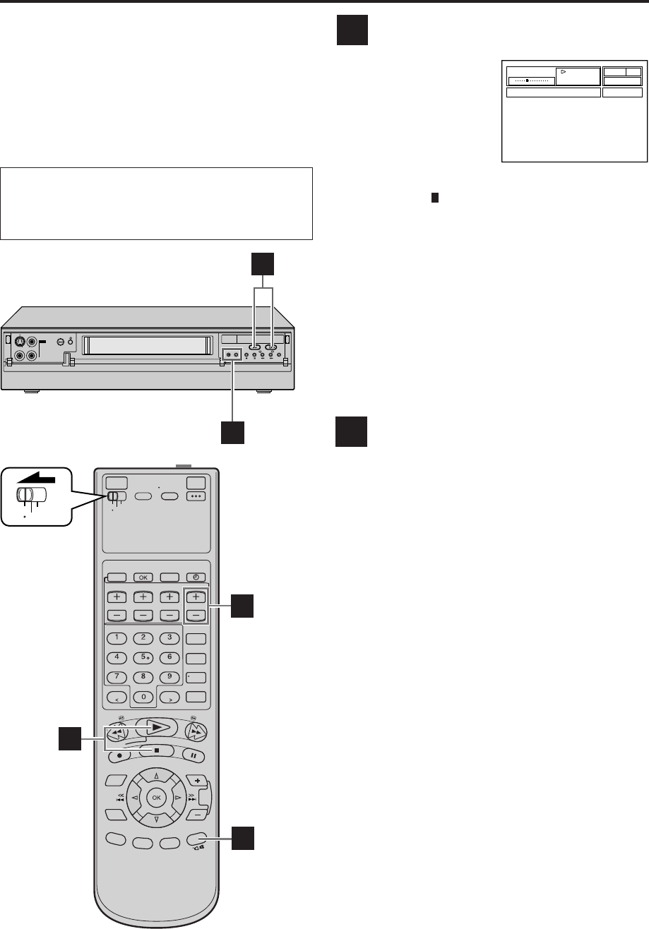
Playing back tape repeatedly
— Repeat Playback
You can play back a tape repeatedly (50 times).
While playing back a tape, press and hold PLAY ( 3 )
for more than 5 seconds.
The play indicator ( # ) on the front display panel starts
flashing slowly, and a tape will be played back 50 times.
To stop playback, press STOP ( 7 ) on the Remote or
STOP/EJECT ( 7/0 ) on the front panel.
NOTE:
For a cassette recorded in D-VHS mode, Repeat Playback is not
possible if the cassette was recorded in LS3 or LS5 mode.
B
BASIC PLAYBACK AND RECORDING (cont.)
A
B E
●Turn on the VCR and the TV, and select the AV
mode on the TV.
●Set the VCR/TV/CABLE/DBS selector on the
Remote to “VCR”.
VCR
TV
CABLE
/DBS
D
C
B
MV8300_U1B-EN21-33 4/1/3, 2:36 PM22
EN 23
Selecting monitor sound
— Audio Monitor
You can select the desired monitor sound.
While playing back a tape on which stereo sound or SAP
sound is recorded, press A. MONITOR on the Remote.
Each time you press the button, sound changes as follows:
S-VHS/VHS
L R : Normally select this.
Hi-Fi sound is played back.
L: Sound on the left Hi-Fi channel is played
back.
R : Sound on the right Hi-Fi channel is played
back.
NORMAL: Sound on the normal track is played back.
MIX: Both sounds on the Hi-Fi track and
normal track are mixed and played back.
D-VHS
L R : Normally select this.
L: Sound on the left channel is played back.
R : Sound on the right channel is played back.
NOTES:
●
The above indication appears when “SUPERIMPOSE” is set to
“ON” (
pg. 57), though the monitor sound changes in
sequence.
●
If the tape being played back has no Hi-Fi sound track, the
normal sound track will be heard regardless of this setting.
C
NORMAL
MIX
L R L R
D
L R L R
Adjusting tracking condition
— Tracking Adjustments
Automatic tracking adjustment
This VCR automatically adjusts the tracking condition.
Whenever you insert a tape and start playback,
automatic tracking starts working and continuously
analyzes the signal to enable optimum picture quality
during playback.
Manual tracking adjustment
If automatic tracking cannot eliminate noises well during
playback, use the manual tracking following the
procedures below.
●You can also use the manual tracking during slow
motion playback ( pg. 33). During slow motion
playback, simply press CHANNEL + or – on the VCR
(or TV/VCR CH + or – on the Remote) to adjust
tracking.
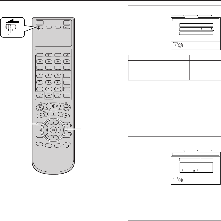
1Activate manual tracking
Press CHANNEL + and – on the front panel at the
same time during playback.
2Eliminate the noises on the TV screen
Press CHANNEL + or –.
●Press it briefly for a fine adjustment, or press and
hold for a coarse adjustment. Watch the screen
and continue adjustment until optimum picture
and sound quality are achieved.
●To reactivate automatic tracking, press CHANNEL
+ and – on the front panel at the same time. The
automatic tracking becomes active again.
MV8300_U1B-EN21-33 4/1/3, 2:36 PM23
24 EN BASIC PLAYBACK AND RECORDING (cont.)
Automatic operations after
rewinding — Next Function Memory
The Next Function Memory “tells” the VCR what to do
after rewinding is complete.
●Ensure that the VCR is in stop mode.
a–For Automatic Playback Start
Press REW ( 1 ), then press PLAY ( 3 ) within 2
seconds.
b–For Automatic Power Off
Press REW ( 1 ), then press POWER within 2
seconds.
c–For Automatic Timer Standby
Press REW ( 1 ), then press TIMER (‰) within 2
seconds.
NOTE:
It is not possible to select the Automatic Timer Standby function
if the cassette’s record safety tab is removed.
Locating beginning of
recordings — Index Search
When recording on this VCR, index codes are placed on
the tape at the beginning of each recording. You can find
and automatically play back from the beginning of any
recording using the Index Search function.
1Start search
While the tape is not running, press 4 or ¢ on
the Remote.
2Access distant code
To access a recording of 2 to 9 index codes away,
press 4 or ¢ repeatedly until the correct
number is displayed on the screen (only if
“SUPERIMPOSE” is set to “ON” ( pg. 57)).
Playback begins automatically when the desired
recording is located.
●If you want to find the very beginning of the
desired program, press REW ( ) or FF ( )
after playback starts.
NOTE:
An index code is not placed on the tape when recording is
resumed from recording pause.
Other Useful functions for playback
(S-VHS/VHS only)
You can also use the following functions for playback.
●Video Calibration ( pg. 54)
When this function is set to “ON”, this VCR checks the
condition of the tape in use during playback and
recording, and compensates to provide the highest-
possible pictures.
●Picture Control ( pg. 54)
This function helps you to adjust the playback picture
quality according to your preference.
●Digital R3 ( pg. 54)
This function applies edge correction to the luminance
signal to enhance details and provides clear pictures.
●Video Stabilizer ( pg. 54)
You can automatically correct vertical vibrations in the
picture when playing back unstable recordings made on
another VCR.
Current position
on the tape
Beginning of the current
program recorded
Beginning of the 2nd next
program recorded
–1 12
–2 3
Previous
program
recorded
Next
program
recorded
2nd next
4¢
F
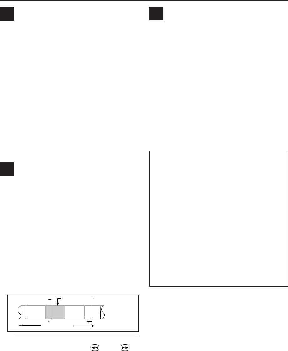
ESkipping unwanted portions
— Skip Search
You can skip over (view at high speed) unwanted
portions of the tape.
Press SKIP SEARCH on the Remote once to 4 times
during playback.
Each press initiates a 30-second period of high speed
playback (up to 2 minutes). When the specified portion
of the tape is skipped, normal playback resumes
automatically.
To return to normal playback during Skip Search, press
PLAY ( 3 ).
NOTE:
It is not possible to perform the Skip Search when you play back
a D-VHS tape recorded in LS5 mode.
G
MV8300_U1B-EN21-33 4/1/3, 2:36 PM24
EN 25
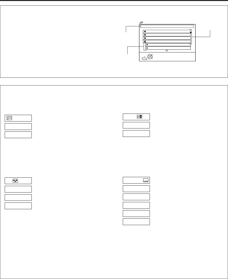
How to read the Video Navigation screen for D-Theater tape*
If you insert a D-Theater tape and then press NAVI, the
following screen appears. Press %fi to move the arrow
to the item that you want to watch, then press OK.
Playback starts automatically after the selected item is
located. The D-Theater indicator lights up when playing
back a D-Theater tape.
* D-Theater is a technical specification based on D-VHS
standards that was developed for HD content. Commercial
D-Theater titles can only be played back on D-VHS digital
recorders bearing the D-Theater logo.
Title
Section
Chapter
EXIT
1. CHAPTER 1
TAPE TITLE: WORLD SOCCER 1 / 4
SELECT
OK
2. CHAPTER 2
3. CHAPTER 3
4. CHAPTER 4
NAVI
SELECT WITH ARROW KEYS
THEN PRESS [OK]
Chapter Navigation
SECTOR 4-1
SECTOR 4-2
Program Selection
PROG. 1
PROG. 2
During normal playback, press TV/VCR CH +/– on
the Remote to select the desired program.
●It is impossible to select the program if the tape
does not contain the multiple programs.
Angle Selection
VIDEO 1
VIDEO 2
VIDEO 3
During normal playback, press the number key "4"
on the Remote to select the desired angle.
●It is impossible to select the angle if the tape does
not contain the multiple angles.
Sound Selection
1. STEREO
2. Dolby D
During normal playback, press A. MONITOR on the
Remote to select the desired sound.
●It is impossible to select the sound if the tape does
not contain the multiple sounds.
Subtitle Selection
OFF
CC1
CC2
CC3
CC4
During normal playback, press SUBTITLE (number
key "6") on the Remote to select the desired subtitle.
●It is impossible to select the subtitle if the tape
does not contain the multiple subtitles.
Some D-Theater tapes or D-VHS tapes may contain the multiple programs, angles, sounds or subtitles. If a tape
contains them, the icons appear on the top right corner of the TV screen when you press OSD.
NOTE:
When you record multiple programs or programs with multiple angles, it is impossible to change program on multiple program
channel and angles with the control of this VCR. Select the desired program or angle with the control of the TV.
MV8300_U1B-EN21-33 4/1/3, 2:36 PM25
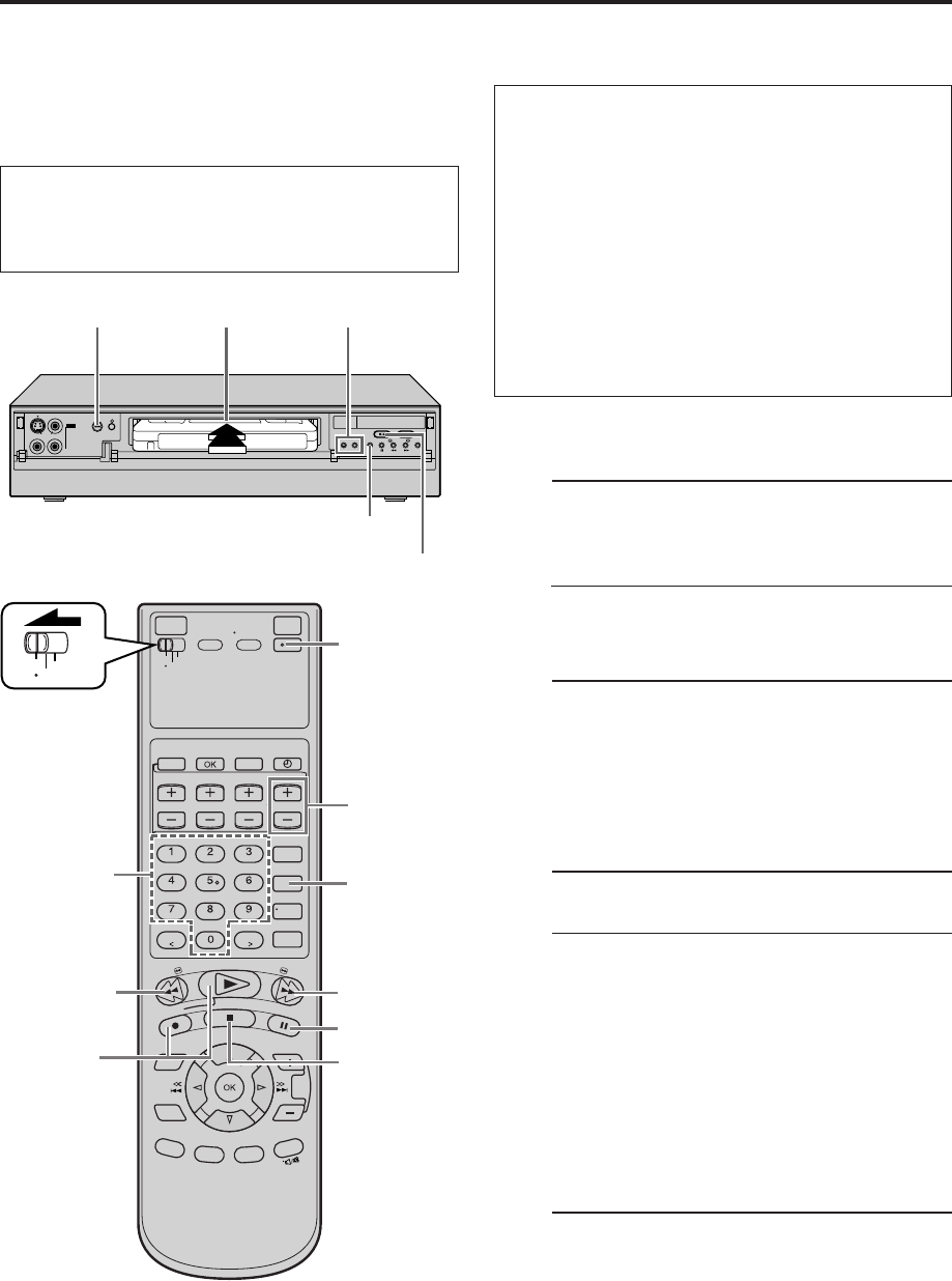
26 EN
IN F-1
+
POWER
STOP/EJECT (7/0)
1 2
4
Basic
Recording
This VCR can check the tape condition during recording
(and playback), and realizes the best possible pictures.
In addition, this VCR is equipped with the Video
Navigation function, which allows you to quickly
locate the programs you have recorded on a tape.
When recording on this VCR, the tapes are
automatically numbered so that every tape recorded
on this VCR has a different tape number. With this
function, the program information such as recording
date, start time, channel number, and recording
speed are also automatically stored in the VCR’s
memory.
●For the Video Navigation function, see page 42.
To memorize the recording date and start time for
the Video Navigation function, the date and clock
must be set correctly.
D-VHS Recording
1Load a D-VHS cassette
Make sure the record safety tab is intact. If not,
cover the hole with adhesive tape before
inserting the cassette.
●The D-VHS indicator lights on the front display
panel and the D-VHS recording mode is
selected automatically.
2Select recording channel
On the front panel:
Press CHANNEL + or –.
On the Remote:
a–Press TV/VCR CH + or –.
or
b–Press the Number keys.
3Set recording speed
Press REC SPEED to set the recording speed.
●The recording speed changes each time
REC SPEED is pressed.
HS: When picture quality and sound quality is
important.
STD: When picture quality and recording time
are important.
LS3: To record for three times longer than in
STD mode, with picture quality that is
equal to or better than S-VHS.
LS5: When recording time is important.
To record for five times longer than in
STD mode.
4Start recording
On the front panel:
Press REC ( ¶ ).
On the Remote:
While holding REC ( ¶ ), press PLAY ( 3 ).
VCR
TV
CABLE
/DBS
2
-b
POWER
PAUSE (8)
STOP (7)
FF ( )
REW (1)
1
4
3
2
-a
BASIC PLAYBACK AND RECORDING (cont.)
●Turn on the VCR and the TV, and select the AV
mode on the TV.
●Set the VCR/TV/CABLE/DBS selector on the
Remote to “VCR”.
MV8300_U1B-EN21-33 4/1/3, 2:36 PM26
EN 27
To pause recording
Press PAUSE ( 8 ). To resume recording, press PLAY ( 3 ).
To stop recording
Press STOP ( 7 ) on the Remote or STOP/EJECT ( 7/0 )
on the front panel.
To rewind the tape (when it is not running)
Press REW ( 1 ).
To fast-forward the tape (when it is not running)
Press FF ( ¡ ).
To eject the tape
Press STOP/EJECT ( 7/0 ) on the front panel when the
tape is not running.
● You can also eject the cassette when the VCR is turned
off.
To turn off the VCR
Press POWER.
It may be unlawful to record or play back
copyrighted material without the consent of the
copyright owner.
S-VHS/VHS Recording
1Load a cassette
Make sure the record safety tab is intact. If not,
cover the hole with adhesive tape before
inserting the cassette.
2Select recording channel
On the front panel:
Press CHANNEL + or –.
On the Remote:
a–Press TV/VCR CH + or –.
or
b–Press the Number keys.
3Set recording speed
Press REC SPEED to set the recording speed.
4Start recording
On the front panel:
Press REC ( ¶ ).
On the Remote:
While holding REC ( ¶ ), press PLAY ( 3 ).
●If “V. CALIBRATION” is set to “ON” (default
setting: pg. 54), this VCR checks the tape
condition for about seven seconds, then starts
recording. This means that the first seven
seconds of the program will not be recorded. If
this is inconvenient for you, follow the steps
below:
1Press REC ( ¶ ) and PAUSE ( 8 ) to start
Video Calibration.
2Then press PLAY ( 3 ) to start recording
after Video Calibration is complete.
Compatibility Of Cassettes And Recording Mode
Cassette
Recording Mode
D-VHS S-VHS VHS
D-VHS Yes Yes Yes
S-VHS No Yes Yes
VHS No Yes* Yes
* To record on the VHS cassette with S-VHS quality, use the
S-VHS ET function (
pg. 59).
NOTES:
●
The D-VHS (MTP), S-VHS, S-VHS ET and VHS mode
recordings are possible with this VCR.
●
To record in the D-VHS mode, use a D-VHS cassette.
●
To record in the S-VHS/VHS mode, you can use a D-VHS,
S-VHS or VHS cassette.
To record in S-VHS mode on D-VHS tapes:
Press D-VHS to turn off the D-VHS indicator. Then, set
“S-VHS MODE” to “ON” ( pg. 58).
To record in VHS mode on D-VHS tapes:
Press D-VHS to turn off the D-VHS indicator. Then, set
“S-VHS MODE” to “OFF” ( pg. 58).
MV8300_U1B-EN21-33 4/1/3, 2:36 PM27
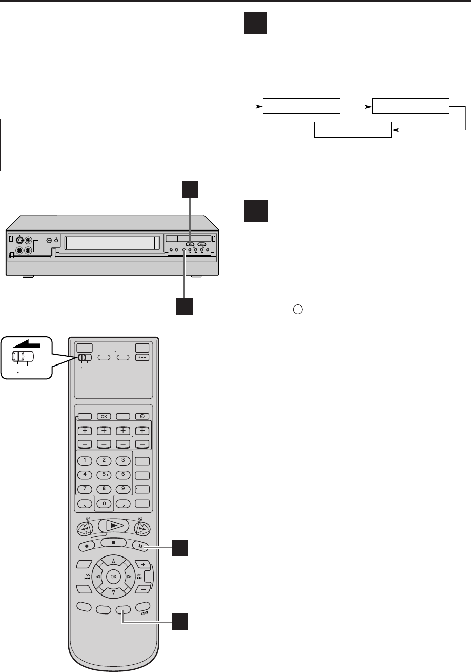
28 EN
IN F-1
+
B
B
Basic
Recording
Features
A
B
Changing display information
Press DISPLAY during recording or recording pause.
Each time you press the button, the front display panel
shows the channel number, clock time, and the
recording speed in sequence.
●To display the VCR status including the time counter,
the channel number and the clock time on the TV
screen, see “Showing on-screen display” ( pg. 29).
Specifying recording length
— Instant Timer Recording (ITR)
You can easily specify the recording length from 30
minutes to 8 hours and the VCR shuts off after recording
is finished.
During recording, press REC ( ¶ ) on the front panel
repeatedly until the recording length you want appears
on the front display panel.
The record ( ) indicator starts flashing.
Each time you press the button, recording length
increases in 30-minute intervals (up to 8 hours).
To cancel an ITR, press STOP ( 7 ) on the Remote or
STOP/EJECT ( 7 / 0 ) on the front panel.
Channel No.
Recording Speed
Clock Time
BASIC PLAYBACK AND RECORDING (cont.)
VCR
TV
CABLE
/DBS
A
B
●Turn on the VCR and the TV, and select the AV
mode on the TV.
●Set the VCR/TV/CABLE/DBS selector on the
Remote to “VCR”.
MV8300_U1B-EN21-33 4/1/3, 2:36 PM28
EN 29
Watching one program while
recording another
1Engage TV mode
During recording...
●Change the TV’s input mode from AV to TV.
2Select channel for viewing
Select the channel you want to watch, on the TV.
Showing on-screen display
When “SUPERIMPOSE” is set to “ON” ( pg. 57), you
can see the current VCR status on the TV screen.
●For more detailed information about the on-screen
display, see page 85.
1Display VCR status on TV screen
During recording or
recording pause, press
OSD on the Remote.
All indications
corresponding to the
current VCR status are
displayed for 5
seconds.
The time counter remains on the screen indicating
the elapsed time.
●The indications are not recorded.
2Exit on-screen display
Press OSD again.
NOTES:
●
The subtitles does not appear while the on-screen display is
displayed.
●
If the VCR is in recording pause mode, “
¶8
” is always
displayed.
●
The VCR status can be also displayed during playback.
●
Even if “SUPERIMPOSE” is set to “OFF” (
pg. 57), the on-
screen display appears when the VCR plays back the blank
portion of a tape and the VCR receives the channel which has
no broadcast. However, on-screen display does not appear
when the input location is selected and no signal is input.
D
C
D-VHS
B E
D-VHS STD
12:00 AM
INDEX -9
CH 123HD
SAP STEREO
LR
VCR
TV
CABLE
/DBS
D
MV8300_U1B-EN21-33 4/1/3, 2:36 PM29
30 EN
Accidental erasure prevention
To prevent accidental recording on a recorded cassette,
remove its record safety tab.
To record on it later, cover the hole with adhesive tape.
Record safety tab
Other useful functions for recording
You can also use the following functions for recording.
●Video Calibration (S-VHS/VHS only) ( pg. 54)
When this function is set to “ON”, this VCR checks the
condition of the tape in use during playback and
recording, and compensates to provide the highest-
possible pictures.
●Second Audio Recording ( pg. 55)
This VCR’s built-in MTS decoder enables reception of
Multichannel TV Sound broadcast.
To record a SAP program received, set “2ND AUDIO REC”
to “ON” using the menu screen.
NOTES:
When the channel is changed on the VCR;
●
The “STEREO” indication appears on the screen for about
5 seconds if the program is a stereo broadcast.
●
The “SAP” indication appears on the screen for about 5
seconds if the program is a SAP broadcast.
●
The “SAP STEREO” indication appears when a stereo
program is accompanied by SAP sound.
●S-VHS Recording Mode ( pg. 58)
This VCR allows you to record on a D-VHS and S-VHS
tape with VHS picture quality.
● S-VHS ET ( pg. 59)
This function allows you to record on VHS tapes with
S-VHS picture quality. Tapes recorded using this function
can be played back on a VCR equipped with the S-VHS ET
BASIC PLAYBACK AND RECORDING (cont.)
function.
MV8300_U1B-EN21-33 4/1/3, 2:36 PM30
EN 31
SPECIAL EFFECT PLAYBACK
Special Effect
Playback
With this VCR, you can enjoy special effect playback
such as high-speed search, variable-speed search, and
still playback and so on.
Locating particular scene
rapidly — Picture Search
7 High-Speed Picture Search:
Possible during normal playback or still picture
playback.
You can rapidly locate a particular scene on the tape.
To do forward picture search, press FF ( ).
To do reverse picture search, press REW ( ).
●If you press and hold the button for more than 2
seconds, simply releasing it cancels the picture search,
and normal playback resumes.
To resume normal playback, press PLAY ( 3 ).
NOTES:
●
The high-speed picture search speed of the D-VHS recording
is 6 times normal playback speed in HS mode, 12 times in
STD mode, 36 times in LS3 mode, 60 times in LS5 mode.
The high-speed picture search speed of the S-VHS/VHS
recording is 11 times normal playback speed in SP mode, 31
times in EP mode.
●
The picture may be distorted at the part where the playback
speed is changed.
●
The still picture may appear during the high-speed picture
search of a tape recorded in D-VHS format on other devices.
A
VCR
TV
CABLE
/DBS
A A
PLAY (3)
4
4
7 Variable-Speed Picture Search (S-VHS/VHS only):
You can change the speed of picture search.
How to use the buttons on the Remote:
To do forward picture search, press ¢ repeatedly.
Each time you press the button, the search speed
increases.
●To decrease the speed during forward picture search
(toward normal playback, then reverse picture search),
press 4 repeatedly.
To do reverse picture search, press 4 repeatedly.
Each time you press the button, the search speed
increases during reverse picture search.
●To decrease the speed during reverse picture search
(toward normal playback, then forward picture search),
press ¢ repeatedly.
To resume normal playback, press PLAY ( 3 ).
●Turn on the VCR and the TV, and select the AV
mode on the TV.
●Set the VCR/TV/CABLE/DBS selector on the
Remote to “VCR”.
MV8300_U1B-EN21-33 4/1/3, 2:36 PM31
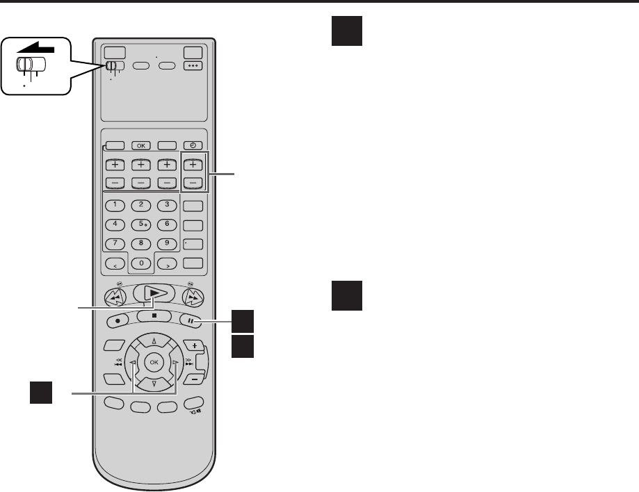
32 EN SPECIAL EFFECT PLAYBACK (cont.)
Viewing still picture
— Still Picture Playback
Press PAUSE ( 8 ) during normal playback.
Playback is freezed and a still picture appears.
To resume normal playback, press PLAY ( 3 ).
NOTES:
●
To obtain a noiseless still picture, it may be necessary to
adjust tracking in slow motion playback before starting still
picture playback.
●
Manual tracking is possible during still picture playback.
During still picture playback, simply press CHANNEL + or –
on the VCR (or TV/VCR CH + or – on the Remote) to adjust
tracking.
Viewing still picture frame by
frame
— Frame-by-Frame Playback
(S-VHS/VHS only)
1Pause during playback
Press PAUSE ( 8 ).
Playback is freezed and a still picture appears.
2Advance or reverse still picture
To advance a still picture, press ¢ (or PAUSE
( 8 )) repeatedly.
To reverse a still picture, press 4 repeatedly.
To resume normal playback, press PLAY ( 3 ).
B
C
VCR
TV
CABLE
/DBS
C -2
PLAY (3)
TV/VCR
CH +/–
B
C -1,-2
MV8300_U1B-EN21-33 4/1/3, 2:36 PM32
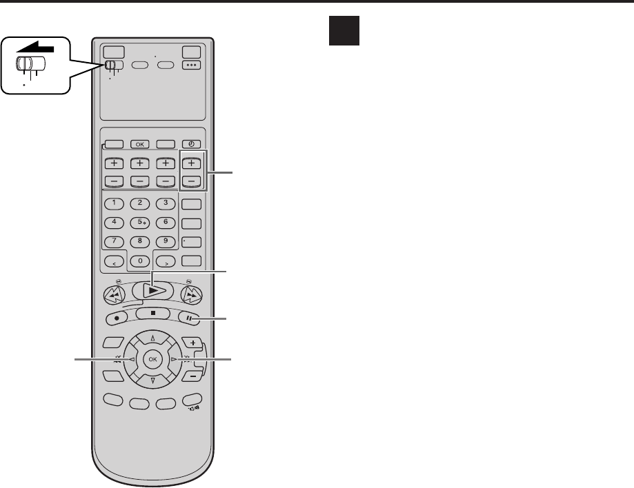
EN 33
Viewing slow motion picture
— Slow Motion Playback
(S-VHS/VHS only)
During normal playback:
Press 4 to decrease the playback speed.
Each time you press the button, the speed decreases
(toward reverse slow motion playback, then reverse
picture search).
●Holding PAUSE ( 8 ) for more than 2 seconds also
starts forward slow motion playback. If you press
PAUSE ( 8 ) again, still picture resumes.
To resume normal playback, press PLAY ( 3 ).
During still picture playback:
Press and hold ¢ to start forward (or 4 to start
reverse) slow motion playback. When you release the
button, slow motion playback stops and a still picture
appears.
●Holding PAUSE ( 8 ) for more than 2 seconds also
starts forward slow motion playback. If you press
PAUSE ( 8 ) again, still picture resumes.
To resume normal playback, press PLAY ( 3 ).
NOTE:
Manual tracking is possible during slow motion playback.
During slow motion playback, simply press CHANNEL + or –
on the VCR (or TV/VCR CH + or –
on the Remote) to adjust
tracking.
D
VCR
TV
CABLE
/DBS
PLAY (3)
PAUSE (8)
TV/VCR
CH +/–
4
4
MV8300_U1B-EN21-33 4/1/3, 2:36 PM33
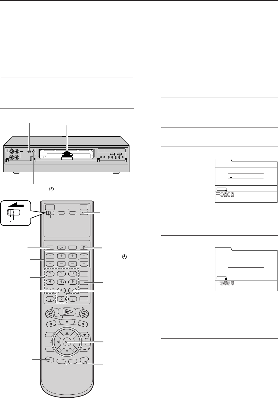
34 EN
IN F-1
+
1
POWER
TIMER ( )
VCR Plus+®
Timer
Programing
Timer recording allows you to program the VCR to
automatically record a broadcast at some future time.
Up to 24 timer recording programs can be made using
VCR Plus+ timer programing or Express timer
programing method (墌 pg. 38) as far as a year in
advance.
The VCR Plus+ timer programing system eliminates the
need to input channel, date, start and stop time data
when programing timer recording settings. Simply key in
the PlusCode number for the TV broadcast you wish to
record and the VCR’s timer will be automatically
programed. (The PlusCode programing numbers are the
numbers next to the program in most TV listing.)
1Load a cassette
Make sure the record safety tab is intact. If not,
cover the hole with adhesive tape, then load it
into the VCR.
●The VCR turns on, and the counter is reset,
automatically.
2Access VCR Plus+ screen
Press PROGRAM on
the Remote.
●The clock must be
set to access the
VCR Plus+ screen.
If you have not set
the clock, the Main
Menu screen
appears after an error message is displayed.
Refer to page 10 for the clock setting
procedure.
3Enter PlusCode number
Press the appropriate
Number keys to input
the PlusCode number
printed in the TV
listings for the TV
broadcast you wish
to record, then press
OK.
Then;
If the Guide Channel Set screen appears
— go to step 4.
If the VCR Plus+ Program screen appears
— go to step 5.
●To make corrections, press CANCEL and input
the correct PlusCode number.
●If an incorrect PlusCode number or the one for
a broadcast already finished has been inputted,
“PLUSCODE NO. ERROR CONFIRM
PLUSCODE NO. THEN RETRY” is displayed for
about 5 seconds, then the VCR Plus+ screen
reappears.
TIMER RECORDING
VCR
TV
CABLE
/DBS
POWER
6
8
WEEKLYDAILY
BACK
2
5
3
TIMER ( )
3 4
7
TIMER PROGRAM
PRESS [+/–] TO SET EXPRESS PROGRAMMING
PRESS NUMBER KEYS [0-9] OR
START STOP DATE CH
EXIT
PROG.
PLUSCODE NUMBER SET
SET
TIMER PROGRAM
PRESS [+/–] TO SET EXPRESS PROGRAMMING
PRESS NUMBER KEYS [0-9] OR
START STOP DATE CH
EXIT
PROG.
PLUSCODE NUMBER SET
SET
1 2 3 4 5
●Turn on the VCR and the TV, and select the AV
mode on the TV.
●Set the VCR/TV/CABLE/DBS selector on the
Remote to “VCR”.
MV8300_U1B-EN34-41 4/1/3, 2:35 PM34
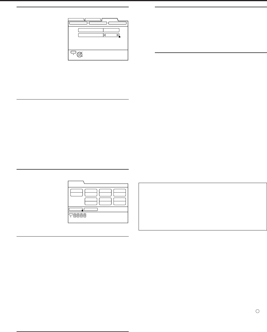
EN 35
4Input receiving channel number
The guide channel
number, which is
assigned to the TV or
cable station for the
PlusCode number
that you entered in
step 3, will appear
automatically on the
Guide Channel Set Up screen.
Press
@
#
to input the number of the channel on
which the broadcast for the PlusCode number is
received on the VCR or cable box, then press
OK.
●The Guide Channel Set screen appears only
when you input the PlusCode number of a
station for which the guide channel number has
not been set previously.
●If you receive your channels with a cable box
and if you have properly set your Controller,
“CABLE CH” appears in place of “VCR CH”. If
not, refer to pages 15 – 17.
In that case, it is possible to change the channel
by 10 channels by pressing and holding
@
#
.
5Check program data
The PlusCode
number you entered
and the
corresponding timer
recording program is
displayed on the
Program screen.
Check to make sure it
is accurate.
●To change the start/stop time, date or channel
setting, press the corresponding buttons to
change the settings; START +/–, STOP +/–,
DATE +/–, TV/VCR CH +/–.
●To timer-record daily or weekly serials, press
DAILY (number “8”) or WEEKLY (number “9”).
“MON – FRI”, “MON – SAT”, “SUN – SAT” or
“EVERY _ _ _” appears on the Program screen.
Pressing the button again makes each
corresponding display disappear.
●For the “SOURCE” setting, refer to page 39.
●If you made a mistake, press BACK to access
the VCR Plus+ screen again and input the
correct PlusCode number.
6Set recording speed
Press REC SPEED to set the recording speed.
IMPORTANT
If you have moved to a different area or if a broadcasting
station’s channel number has been changed, the wrong
VCR CH or CABLE CH number will be displayed on the
Program screen in step 5. When this happens, set the
correct guide channel number for that station. (墌 pg. 36,
“Changing VCR Plus+ Setting”)
NOTES:
●
Even if a power failure occurs, the VCR keeps your timer
programs. However, the clock time is lost if it lasts for more
than 10 minutes.
As a result, when the power is supplied again to this VCR
after the power failure, the following will take place.
1. This VCR starts Auto Clock Set automatically to restore the
clock time.
2. If the clock time is restored correctly and “AUTO TIMER” is
set to “ON”, each timer program you have made will start
at its start time unless its end time has elapsed.
●
If the tape reaches its end during timer recording, “
‰
”, “ ”,
and “
#
” blink.
●
To timer-record cable channels received through a cable box,
be sure to keep the cable box turned on.
7Return to normal screen
Press
@
#
to move the arrow to “CONFIRM”,
then press OK.
“PROGRAM COMPLETED PRESS [TIMER] TO
ENTER TIMER STANDBY MODE” appears on the
screen, then press OK to return to normal screen.
8Engage timer recording standby mode
Press TIMER (‰).
The VCR turns off automatically and “‰” is
displayed on the front display panel.
To use the VCR while it is in timer recording standby
mode
Press TIMER (‰) to cancel the timer recording standby
mode, then press POWER to turn on the VCR.
DO NOT forget to put the VCR into timer recording standby
mode again by pressing TIMER (‰) after you use the VCR;
otherwise, you cannot record the broadcasts you want.
●When “AUTO TIMER” (墌 pg. 57) is set to “ON”, the
timer recording standby mode is automatically
engaged when the VCR is turned off. It is temporarily
canceled when the VCR is turned on. You do not have
to press TIMER (‰) to engage or disengage the timer
recording standby mode.
THEN PRESS [OK]
GUIDE CH 12
VCR CH – –
SELECT WITH ARROW KEYS
SELECT
OK
EXIT
MENU
FUNCTION SET UP
INITIAL SET UPTUNER SET UP
CLOCK SET GUIDE CHANNEL OTHER
CONFIRM CANCEL
10:00 PM
STD (SP)
12/24/03 (WED) 12 CH
CATVEVERY WED
8:00 PM
START TIME
PLUSCODE NO.
12345
STOP TIME DATE
REC SPEED DAILY/WEEKLY
CH
SOURCE
SET PROGRAM WITH [+/–, REC SPEED,
8=DAILY, 9=WEEKLY] THEN PRESS "CONFIRM"
START STOP DATE CH
EXIT
PROG.
TIMER PROGRAM
MV8300_U1B-EN34-41 4/1/3, 2:35 PM35
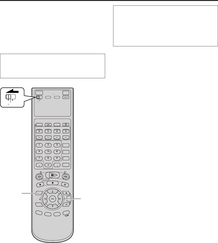
36 EN TIMER RECORDING (cont.)
Changing
VCR Plus+
Setting
IMPORTANT
If you have moved to a different area or if a broadcasting
station’s channel number has been changed, the wrong
VCR CH or CABLE CH number will be displayed on the
Program screen (墌 step 5 on page 35). When this
happens, perform the following steps to set the correct
guide channel number for that station.
To ensure that VCR Plus+ timer recording operates
correctly, it is necessary to set the VCR Plus+ “Guide
Channel Set” for each station. Read the following
information carefully.
VCR Plus+ guide channel matching
The VCR Plus+ programing system assigns a VCR Plus+
guide channel to the TV channels and the cable
channels. These guide channel numbers are also called
the VCR Plus+ channel codes. TV listings often have a
section in chart form, indicating the guide channel
number assigned to each station. For accurate VCR
Plus+ programing, the VCR Plus+ guide channel number
for each station should match the channel number on
which it is received in your area.
NOTES:
●
In many instances, the VCR Plus+ guide channel numbers for
cable and broadcast TV stations DO NOT match the channel
number on which it is received by your VCR or cable box.
Check your TV listing, or contact your cable supplier for
details.
●
Many TV stations can be viewed on cable. Check your TV
listing, or contact your cable supplier for details.
VCR
TV
CABLE
/DBS
2 - 4
1 5
●Turn on the VCR and the TV, and select the AV
mode on the TV.
●Set the VCR/TV/CABLE/DBS selector on the
Remote to “VCR”.
MV8300_U1B-EN34-41 4/1/3, 2:35 PM36
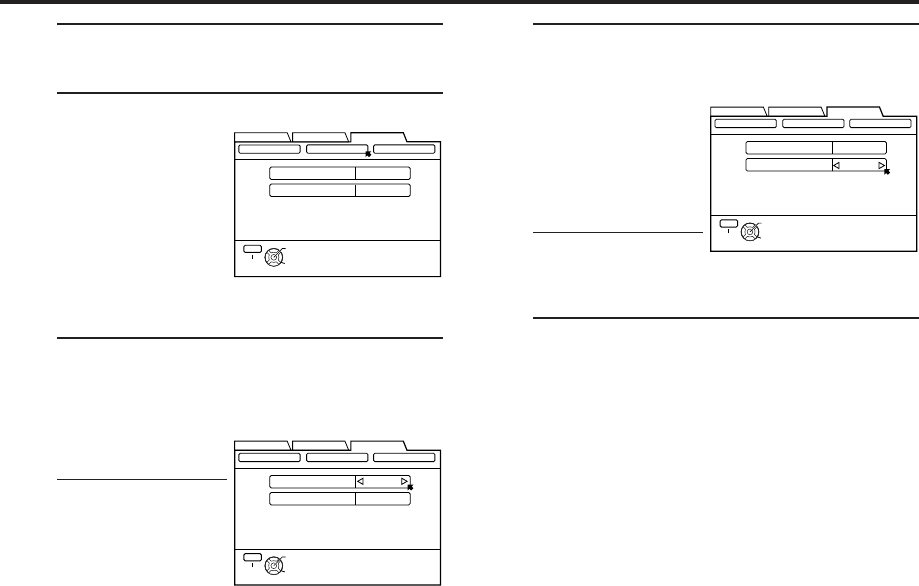
EN 37
1Access Main Menu screen
Press MENU.
2Access Guide Channel Set screen
1Press
@ #
move
the arrow to
“INITIAL SET
UP”, then press fi
or OK.
2Press
@ #
to move
the arrow to
“GUIDE
CHANNEL”, then press fi or OK.
3Input guide channel number
Press
@
#
to input the
VCR Plus+ guide
channel number as
shown in the TV
listing.
●If you receive your
channels with a
cable box and if
you have properly
set your Controller,
“CABLE CH” appears in place of “VCR CH”. If
not, refer to pages 15 – 17 and re-perform the
procedure.
In that case, it is possible to change the channel
by 10 channels by pressing and holding
@ #
in
steps 3 and 4.
4Input receiving channel number
Press %fi to move
the arrow to “VCR
CH”, then press
@
#
to input the number
of the channel on
which the guide
channel’s broadcasts
are received.
●Repeat steps 3 and
4 for each
instance.
5Return to normal screen
Press MENU.
FUNCTION SET UP
INITIAL SET UPTUNER SET UP
THEN PRESS [OK]
CLOCK SET
GUIDE CH 6
VCR CH – –
GUIDE CHANNEL OTHER
SELECT WITH ARROW KEYS
SELECT
OK
EXIT
MENU
(Ex.) When inputting the
guide channel number 6
for WNJU(Ind.)
FUNCTION SET UP
INITIAL SET UPTUNER SET UP
THEN PRESS [OK]
CLOCK SET
GUIDE CH 6
VCR CH
GUIDE CHANNEL OTHER
SELECT WITH ARROW KEYS
SELECT
OK
EXIT
MENU
– –
(Ex.) If WNJU(Ind.) is
received on channel 47
FUNCTION SET UP
INITIAL SET UPTUNER SET UP
THEN PRESS [OK]
CLOCK SET
GUIDE CH 6
VCR CH 47
GUIDE CHANNEL OTHER
SELECT WITH ARROW KEYS
SELECT
OK
EXIT
MENU
MV8300_U1B-EN34-41 4/1/3, 2:35 PM37
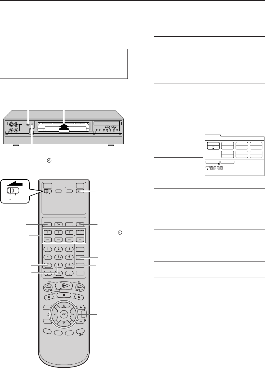
38 EN
IN F-1
+
1
POWER
TIMER ( )
TIMER RECORDING (cont.)
You can directly program the VCR’s timer to record up to
24 broadcasts, as far as a year in advance. Remember,
the clock must be set before you can program the timer
(墌pg. 10).
1Load a cassette
Make sure the record safety tab is intact. If not,
cover the hole with adhesive tape, then load it
into the VCR.
●The VCR turns on, and the counter is reset,
automatically.
2Access VCR PLUS+ screen
Press PROGRAM.
3Access Program screen
Press START +/– once.
4Set program start time
Press START +/–
repeatedly to enter
the time you want
recording to start.
●Press and hold
START +/– to
increase the time in
30-minute intervals.
5Set program stop time
Press STOP +/– repeatedly to enter the time you
want recording to stop.
●Press and hold STOP +/– to increase the time in
30-minute intervals.
6Set program date
Press DATE +/–. (The current date is displayed on
the screen. The date you enter appears in its
place.)
7Set channel number
Press TV/VCR CH +/–.
●If you are using a DBS receiver, see
“ATTENTION FOR DBS RECEIVER USERS” on
next page.
●Holding down TV/VCR CH +/– rapidly changes
the channel numbers.
Express Timer
Programing
VCR
TV
CABLE
/DBS
POWER
TIMER ( )
8
9
0
WEEKLY
DAILY
DBS
2
3 - 7
CONFIRM CANCEL
– –:– – AM
STD (SP)
– –/– –/– –– – –
8:00 PM
START TIME STOP TIME DATE
DAILY/WEEKLY
CH
SOURCE
TIMER PROGRAM
REC SPEED
SET PROGRAM WITH [+/–, REC SPEED
8=DAILY, 9=WEEKLY] THEN PRESS "CONFIRM"
START STOP DATE CH
EXIT
PROG.
EVERY SUN
●Turn on the VCR and the TV, and select the AV
mode on the TV.
●Set the VCR/TV/CABLE/DBS selector on the
Remote to “VCR”.
MV8300_U1B-EN34-41 4/1/3, 2:35 PM38
EN 39
8Set recording speed
Press REC SPEED to set the recording speed.
9Return to normal screen
Press
@
#
to move the arrow to “CONFIRM”,
then press OK.
“PROGRAM COMPLETED PRESS [TIMER] TO
ENTER TIMER STANDBY MODE” appears on the
screen, then press OK to return to normal screen.
0Engage timer recording standby mode
Press TIMER (‰).
The VCR turns off automatically and “‰” is
displayed on the front display panel.
To timer-record daily or weekly serials
Press DAILY (number “8”) or WEEKLY (number “9”)
anytime during steps 4 through 8.
“MON – FRI”, “MON – SAT”, “SUN – SAT” or
“EVERY _ _ _” appears on the Program screen.
●Pressing the button again makes the corresponding
indication disappear.
To use the VCR while it is in timer recording standby
mode
Press TIMER (‰) to cancel the timer recording standby
mode, then press POWER to turn on the VCR.
DO NOT forget to put the VCR into timer recording
standby mode again by pressing TIMER (‰) after you
use the VCR; otherwise, you cannot record the broadcast
you want.
●When “AUTO TIMER” (墌 pg. 57) is set to “ON”, the
timer recording standby mode is automatically
engaged when the VCR is turned off. It is temporarily
canceled when the VCR is turned on. You do not have
to press TIMER (‰) to engage or disengage the timer
recording standby mode.
ATTENTION FOR DBS RECEIVER USERS
If you are using a DBS
receiver (unless “INPUT
CH” is set to “OFF” on
DBS Receiver Set screen
墌 pg. 19), the band
indication (TV, CATV or
DBS) appears under the
channel number
indication (SOURCE).
TV :To timer-record a regular TV broadcast
received on the VCR.
CATV :To timer-record a cable TV broadcast
received on the VCR, or through a cable box
(unless “INPUT CH” is set to “OFF” on
Cable Set Up screen 墌 pg. 16).
DBS :To timer-record a satellite broadcast
received through a DBS receiver.
NOTE:
If “BAND” is set to “TV” on the Tuner Set Up Screen
(
墌
pg. 14) and “INPUT CH” is set to “OFF” on Cable Set
Up screen (
墌
pg. 16), “CATV” will not be displayed on the
Program screen; If “BAND” is set to “CATV” or “INPUT
CH” is set to “ON” on Cable Set Up screen, “TV” will not
be displayed.
If the channel number entered requires that the band
be set, “7=DBS” is displayed on the screen.
If this happens, press the Number key “7 (DBS)” to
select “DBS”.
NOTES:
●
Even if a power failure occurs, the VCR keeps your timer
programs. However, the clock time is lost if it lasts for more
than 10 minutes.
As a result, when the power is supplied again to this VCR
after the power failure, the following will take place.
1. This VCR starts Auto Clock Set automatically to restore the
clock time.
2. If the clock time is restored correctly and “AUTO TIMER” is
set to “ON”, each timer program you have made will start
at its start time unless its end time has elapsed.
●
Programs that start after midnight must have the next day’s
date.
●
After timer recording is completed, the VCR turns off
automatically.
●
You can program the timer recording while a regular
recording is in progress; the menu screens will not be
recorded.
●
If the tape reaches its end during timer recording, “
‰
”, “ ”,
and “
#
” blink.
●
To timer-record cable or satellite channels, be sure to keep
the cable box or DBS receiver turned on.
CONFIRM CANCEL
10:00 PM
STD (SP)
110 CH
DBS
8:00 PM
START TIME STOP TIME DATE
DAILY/WEEKLY
CH
SOURCE
TIMER PROGRAM
REC SPEED
SET PROGRAM WITH [+/–, REC SPEED,7=DBS,
8=DAILY, 9=WEEKLY] THEN PRESS "CONFIRM"
START STOP DATE CH
EXIT
PROG.
12/24/03 (WED)
EVERY WED
MV8300_U1B-EN34-41 4/1/3, 2:35 PM39
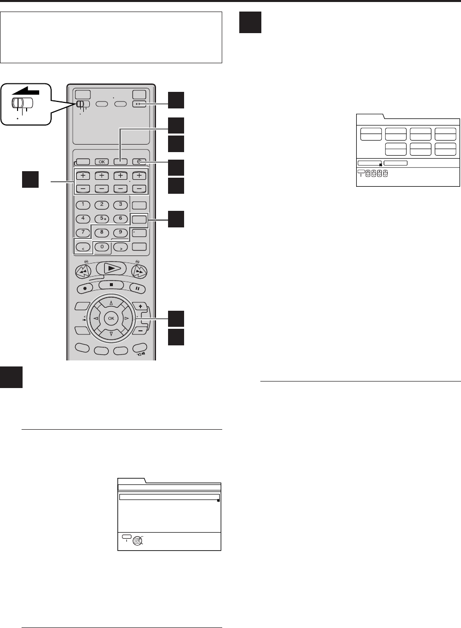
40 EN TIMER RECORDING (cont.)
Checking program settings
1Disengage timer
Press TIMER (‰), then press POWER.
●When “AUTO TIMER” (墌 pg. 57) is set to “ON”,
you do not have to press TIMER (‰).
2Access Program List screen
Press PROG. CHECK.
●The clock must be set
to access the program
list.
If you have not set the
clock, the Main Menu
screen appears after
an error message is
displayed. Refer to page 10 for the clock setting
procedure.
3Access Program screen
Press %fi to select a program, then press OK to
check more detailed information.
●To return to the normal screen, press PROG.
CHECK.
A
B
VCR
TV
CABLE
/DBS
A -1
A -2,3
B -3
A -1
B -4
A -3
B -2
B -2
B -2
Canceling or changing program
settings
1Access Program screen
Repeat steps 1 to 3 in the left column.
2Cancel or change program setting
To cancel a program,
press OK with the
arrow on “CANCEL”,
then press OK with the
arrow on “CONFIRM”.
OR
press CANCEL, then
press OK.
●“PROGRAM CANCELED” appears on the screen,
then press OK to return to the program list.
To change a program, press the appropriate button:
START+/–, STOP+/–, DATE+/–, TV/VCR CH+/–,
DAILY (number “8”), WEEKLY (number “9”) and/or
REC SPEED, then press OK.
●“PROGRAM COMPLETED PRESS [TIMER] TO
ENTER TIMER STANDBY MODE” appears on the
screen, then press OK to return to the program
list.
3Return to normal screen
Press PROG. CHECK.
4Reengage timer recording standby mode
Press TIMER (‰).
●When “AUTO TIMER” (墌 pg. 57) is set to “ON”,
the timer recording standby mode automatically
resumes when you turn off the VCR.
PROGRAM CHECK
THEN PRESS [OK]
SELECT WITH ARROW KEYS
SELECT
OK
EXIT
DATE
12/24/03 (WED) 8:00PM – 10:00PM TUE CATV12CH STD (SP)
12/27/03 (SAT) 11:00PM – 11:45PM MON–FRI VCR47CH STD (SP)
12/28/03 (SUN)10:30PM – 11:45PM MON–FRI DBS110CH STD (SP)
START – STOP DAILY/WEEKLY CH REC SPEED
PROG.CHECK
CONFIRM CANCEL
10:00 PM
STD (SP) WED
12 CH
CATV
8:00 PM
START TIME STOP TIME DATE
DAILY/WEEKLY
CH
SOURCE
REC SPEED
SET PROGRAM WITH [+/–, REC SPEED,
8=DAILY, 9=WEEKLY] THEN PRESS "CONFIRM"
START STOP DATE CH
EXIT
PROG.
TIMER PROGRAM
12/24/03 (WED)
●Turn on the VCR and the TV, and select the AV
mode on the TV.
●Set the VCR/TV/CABLE/DBS selector on the
Remote to “VCR”.
MV8300_U1B-EN34-41 4/1/3, 2:35 PM40
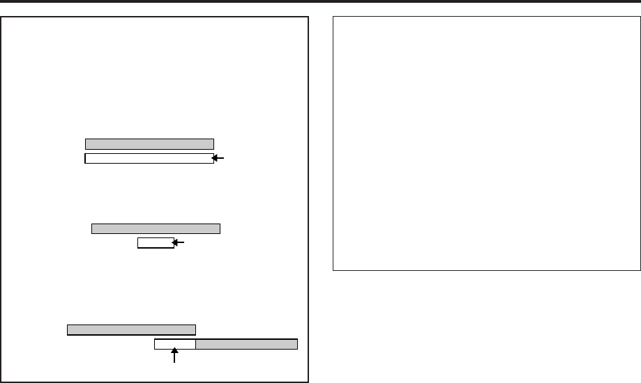
EN 41
Other Useful functions for timer recording
You can also use the following functions for timer
recording.
●Auto Timer (墌 pg. 57)
When “AUTO TIMER” is set to “ON”, the timer recording
standby mode is automatically engaged when the VCR is
turned off. It is temporarily canceled when the VCR is
turned on. You do not have to press TIMER (‰) to engage
or disengage the timer recording standby mode.
●Auto SP = EP Timer (S-VHS/VHS only) (墌 pg. 57)
If there is not enough tape to record the entire broadcast
for recording in SP mode, the VCR automatically switches
to EP mode to allow complete recording. This feature is
especially handy when recording a broadcast of more than
2 hours in length.
ATTENTION
If there is a conflict in the timer schedule and one program
overlaps with another, only the parts shown below in gray
will be recorded.
Pattern 1: The program with the lower program
number will be recorded.
Pattern 2: The program starting earlier will be
recorded.
Pattern 3: The program starting earlier will be
recorded, followed by the remaining portion
of the other program.
10:00 11:00 12:00
CH10
CH40
Program 1
Program 2
Not recorded
10:00 11:00 12:00
CH10
Program 2 Not recorded
Program 1
CH40
10:00 11:00 12:00
CH10
CH40 Not recorded
Program 1
Program 2
MV8300_U1B-EN34-41 4/1/3, 2:35 PM41
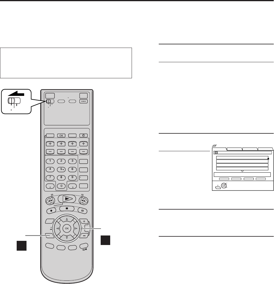
42 EN
Navigation
Playback
This function is useful when you want to quickly find
programs you have recorded on a tape using this VCR.
This function allows you to select a program to watch,
and then automatically search for the beginning of the
program.
1Load a cassette
Insert a tape recorded on this VCR.
●The VCR turns on automatically.
●The tape will run for a few seconds while the
VCR searches for the tape number recorded. If
tape number is found, it will be shown on the
TV screen if “SUPERIMPOSE” is set to “ON”
(墌 pg. 57).
●The counter is reset automatically, however, it
is not completely reset to “0:00:00”.
●If the cassette’s record safety tab has been
removed, playback begins automatically.
2Access Video Navigation screen
Press NAVI.
●After pressing
NAVI, it may take a
few seconds to
access the Title
screen while the
VCR searches for
the Video
Navigation information.
3Select program
Press %fi to select the program you want to
watch, then press OK.
4Start playback
Press
@
#
to move the arrow to “PLAY”, then
press OK.
Playback starts automatically after the selected
program is located.
VIDEO NAVIGATION
VCR
TV
CABLE
/DBS
A
-2,3
A
-1,4
3 - 4
2
BLANK NAVI. SET UP
SEARCH LIBRARY
1. SYDNEY OLYMPIC
PLAY STOP DELETE EDIT
0107 ALL SPORTS TAPE BLANK 2:00 (LS3) 1 / 3
SELECT
OK
2. FOOTBALL
3. EURO 96 ENGLAND
4. PROJECT XYZ
SYDNEY OLYMPIC [SHOW]
12/21/02 SAT 6:30 AM – 5:53 PM DBS 256CH LS3
SELECT WITH ARROW KEYS
THEN PRESS [OK]
EXIT
NAVI
Navigation
●Turn on the VCR and the TV, and select the AV
mode on the TV.
●Set the VCR/TV/CABLE/DBS selector on the
Remote to “VCR”.
NOTES:
●
If you press NAVI while Video Navigation is deactivated, the Navigation Set Up screen appears. Set "NAVIGATION" to "ON"
(
墌
pg. 43).
●
Video Navigation playback is possible only with the tape recorded on this VCR.
●
To record the date and time as the program title in this VCR's memory, make sure the VCR’s clock is set correctly before recording.
●
To record the program information in this VCR’s memory, you must record each program for over the minimum recording time; 5
min for the D-VHS (HS) mode, 10 min for the D-VHS (STD) mode, 30 min for the D-VHS (LS3) mode, 50 min for the D-VHS (LS5)
mode, 5 min for the S-VHS/VHS (SP) mode and 15 min for S-VHS/VHS (EP) mode.
●
Video Navigation may not work properly for some tapes.
●
During playback or when searching for the beginning of a program, a VCR might find two different tape numbers recorded on a
tape. After you remove this tape, the tape will be assigned just one tape number (the smaller one). After this, the higher tape
number will be missing from the memory’s tape number list.
●
Tape program information is stored in this VCR’s memory. If this VCR’s memory is damaged and the program information is lost, it
is impossible to restore that information.
●
After recording a tape on this VCR, write the tape number on a label and affix the label to the tape in order to allow you to find the
tape by its number.
●
The on-screen display is output to the TV with S-VIDEO, VIDEO, COMPONENT VIDEO signal in 480i image format.
MV8300_U1B-EN42-47 4/1/3, 2:34 PM42
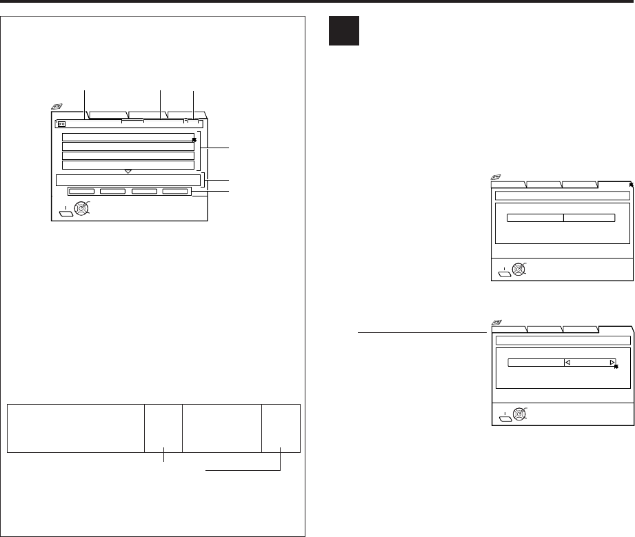
EN 43
Deactivating Video Navigation
If you do not want to store program information, you can
deactivate the Video Navigation function.
1Access Video Navigation screen
Press NAVI.
2Access Navigation Set Up screen
Press %fi
@
#
to move
the arrow to “NAVI. SET
UP”, then press fi or
OK.
3Deactivate Video Navigation
Press
@
#
.
●Each time you press
@#
, Video Navigation
turns “ON” or “OFF”.
4Return to normal screen
Press NAVI.
NOTE:
If you press NAVI
when a cassette is not loaded, “NO TAPE!”
appears on the TV screen. If the VCR does not recognize the
tape number of the loaded cassette, “UNRECOGNIZED TAPE
NUMBER!” appears on the TV screen.
A
How to read the Video
Navigation screen
1Tape number and tape title
2Maximum blank time on the tape
3[Page No./Total Page No.] (only 4 programs can be
shown at a time)
4Program title included on a tape
5The detailed program information currently
selected (date, channel, category, start time, end
time, recording speed)
6Operational commands
SYDNEY OLYMPIC
8:00 (LS3)
BLANK
2:00
(LS3)
EURO 96
ENGLAND
4:00 (LS3)
BLANK
1:00
(LS3)
Blank part*
*“BLANK” appears for non-recorded part, the part
whose information has been deleted manually
(墌pg. 52), or the part where new program has
been recorded.
Example
BLANK NAVI. SET UP
SEARCH LIBRARY
1. SYDNEY OLYMPIC
PLAY STOP DELETE EDIT
0107 ALL SPORTS TAPE BLANK 2:00 (LS3) 1 / 3
SELECT
OK
2. FOOTBALL
3. EURO 96 ENGLAND
4. PROJECT XYZ
SYDNEY OLYMPIC [
SHOW]
12/21/02 SAT 6:30 AM – 5:53 PM DBS 256CH LS3
SELECT WITH ARROW KEYS
THEN PRESS [OK]
EXIT
NAVI
Navigation
123
4
5
6
BLANK NAVI. SET UP
SEARCH LIBRARY
NAVIGATION
NAVIGATION SET UP USED MEMORY 66%
OFF
SELECT
OK
EXIT
NAVI
SELECT WITH ARROW KEYS
THEN PRESS [OK]
Navigation
BLANK NAVI. SET UP
SEARCH LIBRARY
NAVIGATION
NAVIGATION SET UP USED MEMORY 66%
OFF
SELECT
OK
EXIT
NAVI
SELECT WITH ARROW KEYS
THEN PRESS [OK]
Navigation
MV8300_U1B-EN42-47 4/1/3, 2:34 PM43
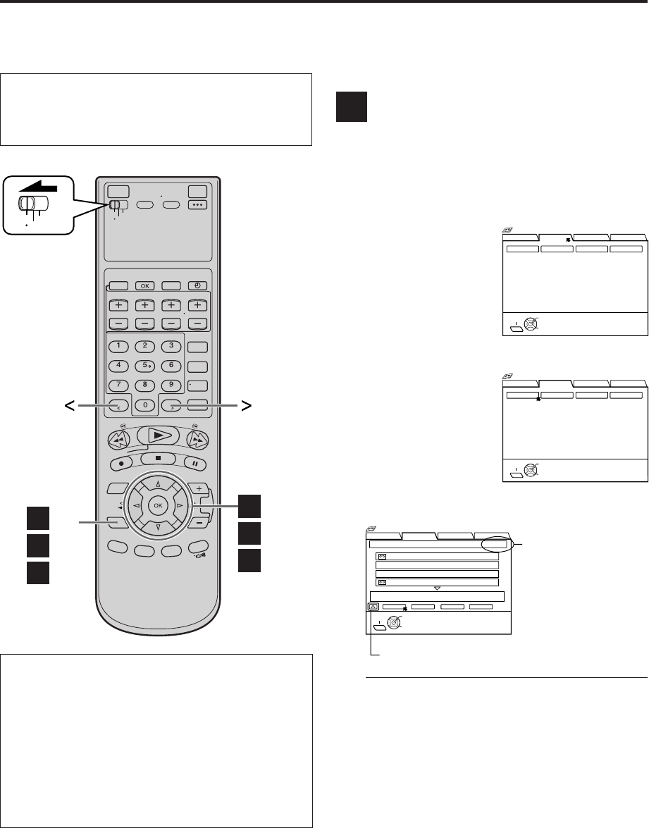
44 EN VIDEO NAVIGATION (cont.)
Finding Tapes You can find a tape you want using Video Navigation.
You have four methods to find tapes; by tape number, by
program title, by category, by recording date, and by
tape remaining time.
Finding by tape number
Use the Remote to do the following operations.
1Access Video Navigation screen
Press NAVI.
2Access Library screen
Press %fi
@
#
to move
the arrow to “LIBRARY”,
then press fi or OK.
3Access tape number list screen
Press
@
#
to move the
arrow to “TAPE
NUMBER”, then press
OK.
The tape number list
screen appears, being
sorted by the tape
numbers.
4Confirm tape number lists
●“*” is displayed beside the tape number of the
loaded cassette.
●The cassette mark is displayed on the left of the
tape title. The items without the cassette marks
are the program titles included in the tape.
●To go to another page of the lists, press < or >.
●To play back the desired program, refer to “To
play back a selected program on the list screen”
in the left column.
5Return to normal screen
Press NAVI.
A
VCR
TV
CABLE
/DBS
B
-2,3
A
-2–4
C
-2,3
B
-4
A
-1,5
C
-4
BLANK NAVI. SET UP
SEARCH LIBRARY
TITLE CATEGORY DATE
TAPE NUMBER
SELECT
OK
EXIT
NAVI
SELECT WITH ARROW KEYS
THEN PRESS [OK]
Navigation
BLANK NAVI. SET UP
SEARCH LIBRARY
TITLE CATEGORY DATE
TAPE NUMBER
SELECT
OK
EXIT
NAVI
SELECT WITH ARROW KEYS
THEN PRESS [OK]
Navigation
●Turn on the VCR and the TV, and select the AV
mode on the TV.
●Set the VCR/TV/CABLE/DBS selector on the
Remote to “VCR”.
1st page (out of 3
pages in this
example) of the tape
number lists is
shown.
BLANK NAVI. SET UP
SEARCH LIBRARY
0016 EURO 2000
SEARCH RETURN DELETE EDIT
TAPE NUMBER LIST 1 / 3
SELECT
OK
0017* 2. ENGLAND VS BRAZIL
0017* 1. JAPAN VS KOREA
0017* SOCCER
SOCCER [
SPORT]
12/21/02 SAT 6:30 AM – 5:53 PM DBS 256CH LS3
NAVI
EXIT SELECT WITH ARROW KEYS
THEN PRESS [OK]
Navigation
To play back a selected program on the list
screen
1Select the program that you want to watch, then
press OK.
2Insert the corresponding tape.
3Press OK again with the arrow on “SEARCH”.
4Confirm that the desired program is highlighted,
then press OK.
●Playback starts automatically after the selected
program is located.
Switch for changing the order
MV8300_U1B-EN42-47 4/1/3, 2:35 PM44
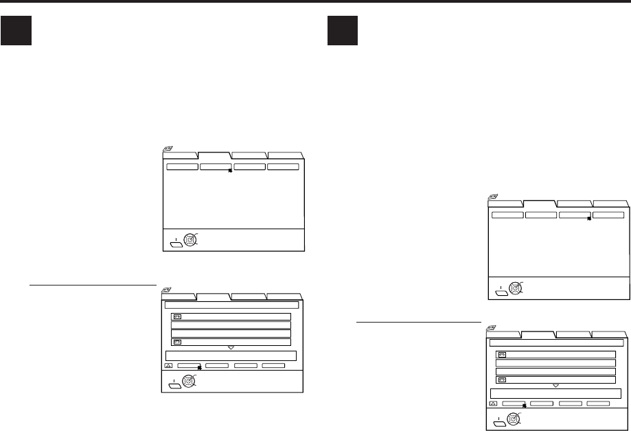
EN 45
Finding by program title
Use the Remote to do the following operations.
1Follow steps 1 to 2 on page 44, then go to
the following steps
2Access title screen
Press
@
#
to move the
arrow to “TITLE”, then
press OK.
3Confirm lists
●“*” is displayed
beside the tape
number of the loaded
cassette.
●The cassette mark is
displayed on the left
of the tape title. The
items without the
cassette marks are the program titles included in
the tape.
●To go to another page of the lists, press < or >.
●To play back the desired program, refer to “To
play back a selected program on the list screen”
on page 44.
4Return to normal screen
Press NAVI.
BFinding by category
Use the Remote to do the following operations.
To find a program by category, be sure to select program
category in advance (墌 pg. 50).
1Follow steps 1 to 2 on page 44, then go to
the following steps
2Access category screen
Press
@
#
to move the
arrow to “CATEGORY”,
then press OK.
3Confirm lists
●“*” is displayed
beside the tape
number of the loaded
cassette.
●The cassette mark is
displayed on the left
of the tape title. The
items without the
cassette marks are the program titles included in
the tape.
●To go to another page of the lists, press < or >.
●To play back the desired program, refer to “To
play back a selected program on the list screen”
on page 44.
4Return to normal screen
Press NAVI.
C
BLANK NAVI. SET UP
SEARCH LIBRARY
TITLE CATEGORY DATE
TAPE NUMBER
SELECT
OK
EXIT
NAVI
SELECT WITH ARROW KEYS
THEN PRESS [OK]
Navigation
BLANK NAVI. SET UP
SEARCH LIBRARY
TITLE CATEGORY DATE
TAPE NUMBER
SELECT
OK
EXIT
NAVI
SELECT WITH ARROW KEYS
THEN PRESS [OK]
Navigation
BLANK NAVI. SET UP
SEARCH LIBRARY
0016 EURO 2000
SEARCH RETURN DELETE EDIT
CATEGORY LIST 1 / 3
SELECT
OK
0017* 2. ENGLAND VS BRAZIL
0017* 1. JAPAN VS KOREA
0017* SOCCER
SOCCER [
SPORT]
12/21/02 SAT 6:30 AM – 5:53 PM DBS 256CH LS3
NAVI
EXIT SELECT WITH ARROW KEYS
THEN PRESS [OK]
Navigation
BLANK NAVI. SET UP
SEARCH LIBRARY
0016 EURO 2000
SEARCH RETURN DELETE EDIT
TITLE LIST 1 / 3
SELECT
OK
0017* 2. ENGLAND VS BRAZIL
0017* 1. JAPAN VS KOREA
0017* SOCCER
SOCCER [
SPORT]
12/21/02 SAT 6:30 AM – 5:53 PM DBS 256CH LS3
NAVI
EXIT SELECT WITH ARROW KEYS
THEN PRESS [OK]
Navigation
MV8300_U1B-EN42-47 4/1/3, 2:35 PM45
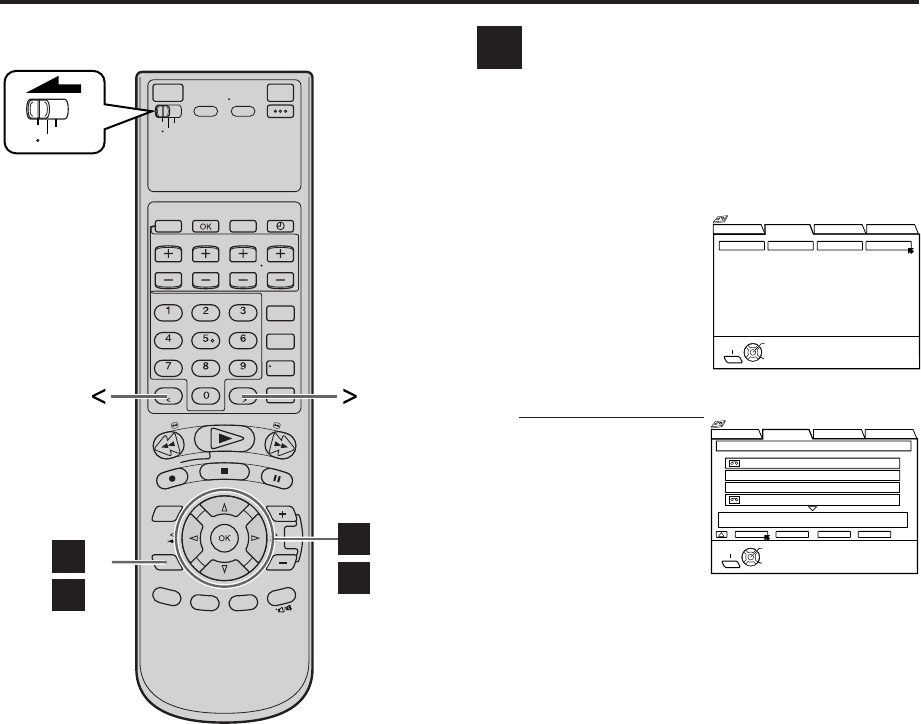
46 EN VIDEO NAVIGATION (cont.)
VCR
TV
CABLE
/DBS
E -2–4,6
D -2,3
E -1
D -4
Finding by recording date
Use the Remote to do the following operations.
1Follow steps 1 to 2 on page 44, then go to
the following steps
2Access date screen
Press
@
#
to move the
arrow to “DATE”, then
press OK.
The list screen appears,
being sorted by the
recording date.
3Confirm lists
●“*” is displayed
beside the tape
number of the loaded
cassette.
●The cassette mark is
displayed on the left
of the tape title. The
items without the
cassette marks are the program titles included in
the tape.
●To go to another page of the lists, press < or >.
●To play back the desired program, refer to “To
play back a selected program on the list screen”
on page 44.
4Return to normal screen
Press NAVI.
BLANK NAVI. SET UP
SEARCH LIBRARY
TITLE CATEGORY DATE
TAPE NUMBER
SELECT
OK
EXIT
NAVI
SELECT WITH ARROW KEYS
THEN PRESS [OK]
Navigation
BLANK NAVI. SET UP
SEARCH LIBRARY
0016 EURO 2000
SEARCH RETURN DELETE EDIT
DATE LIST 1 / 3
SELECT
OK
0017* 2. ENGLAND VS BRAZIL
0017* 1. JAPAN VS KOREA
0017* SOCCER
SOCCER [
SPORT]
12/21/02 SAT 6:30 AM – 5:53 PM DBS 256CH LS3
NAVI
EXIT SELECT WITH ARROW KEYS
THEN PRESS [OK]
Navigation
D
MV8300_U1B-EN42-47 4/1/3, 2:35 PM46
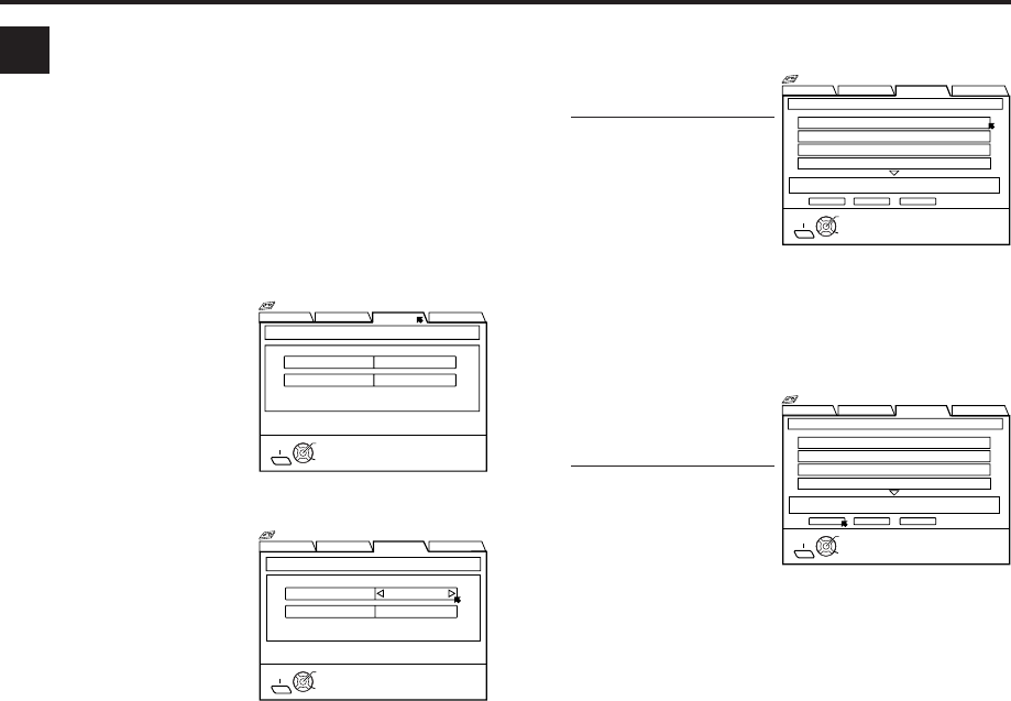
EN 47
Finding blank space
You can find a tape whose remaining time is enough for
a program you want to record.
Use the Remote to do the following operations.
1Access Video Navigation screen
Press NAVI.
E
2Access Blank Space List screen
Press %fi
@
#
to move
the arrow to “BLANK”,
then press fi or OK.
3Set condition
Press %fi to move the
arrow to “RECORDING
MODE”, then press
@
#
to select the recording
speed.
Press %fi to move the
arrow to “BLANK
TIME”, then press
@
#
to select the blank time.
Then press OK.
BLANK NAVI. SET UP
SEARCH LIBRARY
SELECT
OK
EXIT
NAVI
RECORDING MODE
BLANK SPACE LIST RECORDING CONDITION
LS3
BLANK TIME 2:00
SELECT WITH ARROW KEYS
THEN PRESS [OK]
Navigation
BLANK NAVI. SET UP
SEARCH LIBRARY
RECORDING MODE
BLANK SPACE LIST RECORDING CONDITION
LS3
SELECT
OK
EXIT
BLANK TIME 2:00
NAVI
SELECT WITH ARROW KEYS
THEN PRESS [OK] TO LIST
Navigation
4Select tape number
Press %fi, then press
OK.
●To go to another page
of the lists, press < or
>.
5Load a cassette
Insert the cassette whose number you have found in
step 4.
6Select blank
Press
@
#
to move the
arrow to “STOP”, then
press OK.
●The VCR will start
search for the
beginning of the
blank part, then stop.
7Prepare for recording
See page 26 for recording.
BLANK NAVI. SET UP
SEARCH LIBRARY
0003 10:00 BLANK
0004 23:00 BLANK
0001 17:00 BLANK
0002 12:00 BLANK
SEARCHSTOP RETURN
BLANK SPACE LIST 10:00 LS5 1 / 3
SELECT
OK
TITLE
11/01/29 MON 11:34 AM
EXIT
NAVI
SELECT WITH ARROW KEYS
THEN PRESS [OK]
Navigation
BLANK NAVI. SET UP
SEARCH LIBRARY
0003 10:00 BLANK
0004 23:00 BLANK
0001 17:00 BLANK
0002 12:00 BLANK
SEARCHSTOP RETURN
BLANK SPACE LIST 10:00 LS5
SELECT
OK
TITLE
11/01/29 MON 11:34 AM
EXIT
NAVI
SELECT WITH ARROW KEYS
THEN PRESS [OK]
1 / 3
Navigation
MV8300_U1B-EN42-47 4/1/3, 2:35 PM47
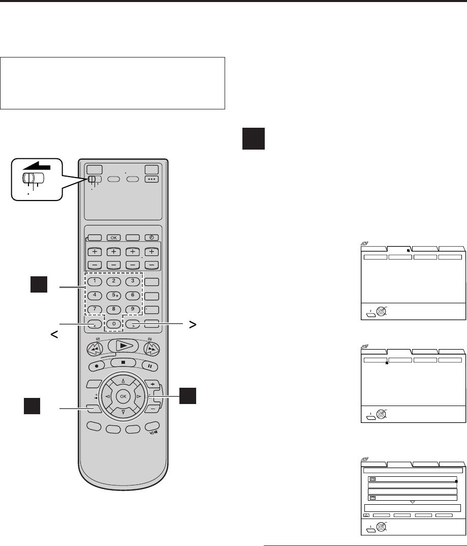
48 EN
Editing Titles When you record a TV program on this VCR, the VCR
automatically records the recording start time, date, and
channel in each program title. If the tape is recorded for
the first time, the tape number and the date and time are
recorded in the tape title. You can then edit the tape title
and the program titles as you like. You can also edit the
category in the program title.
In short, you can use the Video Navigation function to
create your own video tape library.
Editing tape title
When you want to edit the tape title, follow the
procedure below by using the Remote.
1Access Video Navigation screen
Press NAVI.
2Access Library screen
Press %fi
@
#
to move
the arrow to
“LIBRARY”, then press
fi or OK.
3Access tape number
list screen
Press
@
#
to move the
arrow to “TAPE
NUMBER”, then press
OK.
The tape number list
screen appears, being
sorted by the tape numbers.
4Select tape number
Press %fi to select the
tape number for which
you want to edit the
title, then press OK.
●“*” is displayed beside the tape number of the
loaded cassette.
●The cassette mark is displayed on the left of the
tape title. The items without the cassette marks
are the program titles included in the tape.
●To go to another page of the lists, press < or >.
A
VCR
TV
CABLE
/DBS
A
-6
A
-1,7
Number keys
CANCEL
A
-2–6
VIDEO NAVIGATION (cont.)
BLANK NAVI. SET UP
SEARCH LIBRARY
TITLE CATEGORY DATE
TAPE NUMBER
SELECT
OK
EXIT
NAVI
SELECT WITH ARROW KEYS
THEN PRESS [OK]
Navigation
BLANK NAVI. SET UP
SEARCH LIBRARY
TITLE CATEGORY DATE
TAPE NUMBER
SELECT
OK
EXIT
NAVI
SELECT WITH ARROW KEYS
THEN PRESS [OK]
Navigation
BLANK NAVI. SET UP
SEARCH LIBRARY
0016 EURO 2000
SEARCH RETURN DELETE EDIT
TAPE NUMBER LIST 1 / 3
SELECT
OK
0017* 2. ENGLAND VS BRAZIL
0017* 1. JAPAN VS KOREA
0017* SOCCER
SOCCER [
SPORT]
12/21/02 SAT 6:30 AM – 5:53 PM DBS 256CH LS3
NAVI
EXIT SELECT WITH ARROW KEYS
THEN PRESS [OK]
Navigation
●Turn on the VCR and the TV, and select the AV
mode on the TV.
●Set the VCR/TV/CABLE/DBS selector on the
Remote to “VCR”.
MV8300_U1B-EN48-52 4/1/3, 2:34 PM48
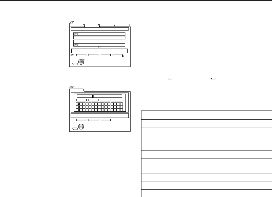
EN 49
5Access edit screen
Press
@
#
to move the
arrow to “EDIT”, then
press OK.
6Enter title
1Press %fi
@
#
to
move the arrow on
the desired
character or
symbol, then press
OK.
OR
Press the Number
keys to enter the title.
•For entering the characters as the title, refer to
“How to enter the characters and symbols”
on the right column. (In this example, enter
“JVC NEWS”.)
2Press %fi
@
#
to move the arrow to “ENTER”,
then press OK.
7Return to normal screen
Press NAVI.
NOTES:
●
If you want to delete a character, select the character, then
press CLEAR or press OK
with the arrow on “ERASE”.
●
If you want to delete all characters, press OK with the arrow
on “ALL ERASE”.
NUMBER KEY CHARACTERS
1. , ? – + * / [ ] 1
2A B C a b c 2
3D E F d e f 3
4G H I g h i 4
5J K L j k l 5
6M N O m n o 6
7P Q R S p q r s 7
8T U V t u v 8
9W X Y Z w x y z 9
00 _(space)
How to enter the characters and symbols with the
number keys on the Remote
Press the Number keys, then press > to enter each
character.
Refer to the example below.
(Ex.) Enter “JVC NEWS”.
1Press 5 (JKL) once to enter “J”, then press >.
2Press 8 (TUV) three times to enter “V”, then press >.
3Press 2 (ABC) three times to enter “C”, then press >.
4Press 0 ( ) twice to enter “ (space)”, then press >.
5Press 6 (MNO) twice to enter “N”, then press >.
6Press 3 (DEF) twice to enter “E”, then press >.
7Press 9 (WXYZ) once to enter “W”, then press >.
8Press 7 (PQRS) four times to enter “S”, then press >.
BLANK NAVI. SET UP
SEARCH LIBRARY
0016 EURO 2000
SEARCH RETURN DELETE EDIT
TAPE NUMBER LIST 1 / 3
SELECT
OK
0017* 2. ENGLAND VS BRAZIL
0017* 1. JAPAN VS KOREA
0017* SOCCER
SOCCER [SPORT]
12/21/02 SAT 6:30 AM – 5:53 PM DBS 256CH LS3
NAVI
EXIT SELECT WITH ARROW KEYS
THEN PRESS [OK]
Navigation
EDIT TITLE
RETURN ENTER
EDIT CATEGORY
SELECT
OK
SYDNEY OLYMPIC [
SHOW]
12/21/02 MON 6:30 AM - 5:53 PM DBS 256CH LS3
EXIT
SYDNEY OLYMPIC
ERASE NEXT
><
BACK
ALL ERASE
NAVI
SELECT WITH ARROW KEYS
THEN PRESS [OK]
Navigation
MV8300_U1B-EN48-52 4/1/3, 2:34 PM49
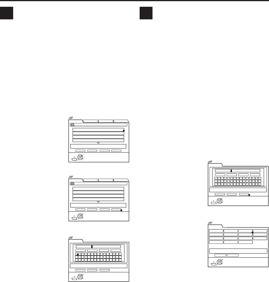
50 EN
BEntering or Editing program
title
When you want to edit the program title, follow the
procedure below by using the Remote.
1Load a cassette
Insert a tape on which there is a program you want
to edit.
2Access Video Navigation screen
Press NAVI.
3Select program
Press %fi to select the
program you want to
edit, then press OK.
4Access edit screen
Press
@
#
to move the
arrow to “EDIT”, then
press OK.
5Enter title
1Press %fi
@
#
to
move the arrow on
the desired
character or
symbol, then press
OK.
OR
Press the Number
keys to enter the title.
•For entering the characters as the title, refer to
“How to enter the characters and symbols”
on page 49. (In this example, enter “JVC
NEWS”.)
2Press %fi
@
#
to move the arrow to “ENTER”,
then press OK.
6Return to normal screen
Press NAVI.
CEditing program category
When you want to change the program category, follow
the procedure below by using the Remote.
1Load a cassette
Insert a tape on which there is a program you want
to edit.
2Access Video Navigation screen
Press NAVI.
3Select program
Press %fi to select the program you want to edit,
then press OK.
4Access edit screen
Press
@
#
to move the arrow to “EDIT”, then press
OK.
5Access category screen
Press %fi
@
#
to move
the arrow to “EDIT
CATEGORY”, then
press OK.
6Select category
Press %fi
@
#
to select
the category you want,
then press OK.
7Return to normal screen
Press NAVI.
VIDEO NAVIGATION (cont.)
BLANK NAVI. SET UP
SEARCH LIBRARY
1. SYDNEY OLYMPIC
PLAY STOP DELETE EDIT
0107 ALL SPORTS TAPE BLANK 2:00 (LS3) 1 / 3
SELECT
OK
2. FOOTBALL
3. EURO 96 ENGLAND
4. PROJECT XYZ
SYDNEY OLYMPIC [
SHOW]
12/21/02 SAT 6:30 AM – 5:53 PM DBS 256CH LS3
SELECT WITH ARROW KEYS
THEN PRESS [OK]
EXIT
NAVI
Navigation
EDIT TITLE
RETURN ENTER
EDIT CATEGORY
SELECT
OK
SYDNEY OLYMPIC [
SHOW]
12/21/02 MON 6:30 AM - 5:53 PM DBS 256CH LS3
EXIT
SYDNEY OLYMPIC
ERASE NEXT
><
BACK
ALL ERASE
NAVI
SELECT WITH ARROW KEYS
THEN PRESS [OK]
Navigation
EDIT CATEGORY
MOVIES
CHILD
MUSIC COMEDY CLASSIC SHOPPING
OTHERS MISCELLANY
RELIGION
RETURN EDIT TITLE
EDUCATION SERIES SPECIAL
SOAPS SPORTS NEWS
SELECT
OK
EXIT
NAVI
SELECT WITH ARROW KEYS
THEN PRESS [OK]
Navigation
SYDNEY OLYMPIC [
SHOW]
12/21/02 MON 6:30 AM - 5:53 PM DBS 256CH LS3
EDIT TITLE
RETURN ENTER
EDIT CATEGORY
SELECT
OK
EXIT
SYDNEY OLYMPIC
ERASE NEXT
><
BACK
ALL ERASE
NAVI
SELECT WITH ARROW KEYS
THEN PRESS [OK]
Navigation
SYDNEY OLYMPIC [SHOW]
12/21/02 MON 6:30 AM - 5:53 PM DBS 256CH LS3
MV8300_U1B-EN48-52 4/1/3, 2:34 PM50
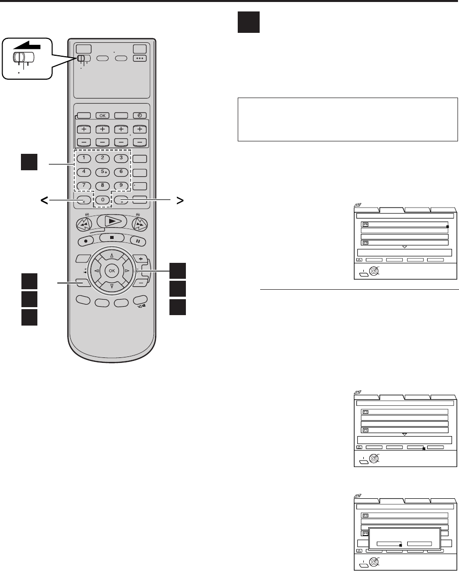
EN 51
Deleting tape information
When you want to delete the entire tape information
(information for all recorded programs on the tape),
follow the procedure below by using the Remote.
•Tape information for the Video Navigation function is
deleted, but the recorded programs will not be erased.
ATTENTION
Once the information is deleted, it is impossible to
restore that information.
1Follow steps 1 to 3 on page 48, then go to
the following steps
2Select tape number
Press %fi to select the
tape number for which
you want to edit the
title, then press OK.
●“*” is displayed beside the tape number of the
loaded cassette.
●The cassette mark is displayed on the left of the
tape title. The items without the cassette marks
are the program titles included in the tape.
●To go to another page of the lists, press < or >.
3Access delete screen
Press
@
#
to move the
arrow to “DELETE”,
then press OK.
4Delete tape information
Press
@
#
to move the
highlight bar to “YES”,
then press OK.
5Return to normal screen
Press NAVI.
D
VCR
TV
CABLE
/DBS
B -5
B -2,6
C -2,7
D -5
B -3–5
C -3–6
D -2–4
BLANK NAVI. SET UP
SEARCH LIBRARY
0016 EURO 2000
SEARCH RETURN DELETE EDIT
TAPE NUMBER LIST 1 / 3
SELECT
OK
0017* 2. ENGLAND VS BRAZIL
0017* 1. JAPAN VS KOREA
0017* SOCCER
SOCCER [
SPORT]
12/21/02 SAT 6:30 AM – 5:53 PM DBS 256CH LS3
NAVI
EXIT SELECT WITH ARROW KEYS
THEN PRESS [OK]
Navigation
BLANK NAVI. SET UP
SEARCH LIBRARY
0016 EURO 2000
SEARCH RETURN DELETE EDIT
TAPE NUMBER LIST 1 / 3
SELECT
OK
0017* 2. ENGLAND VS BRAZIL
0017* 1. JAPAN VS KOREA
0017* SOCCER
SOCCER [SPORT]
12/21/02 SAT 6:30 AM – 5:53 PM DBS 256CH LS3
NAVI
EXIT SELECT WITH ARROW KEYS
THEN PRESS [OK]
Navigation
BLANK NAVI. SET UP
SEARCH LIBRARY
0016 EURO 2000
SEARCH RETURN DELETE EDIT
TAPE NUMBER LIST 1 / 3
SELECT
OK
0017* 2. ENGLAND VS BRAZIL
0017* 1. JAPAN VS KOREA
0017* SOCCER
SOCCER [
SPORT]
12/21/02 SAT 6:30 AM – 5:53 PM DBS 256CH LS3
NAVI
EXIT SELECT WITH ARROW KEYS
THEN PRESS [OK]
Navigation
PROGRAM INFO
DELETE?
NO YES
MV8300_U1B-EN48-52 4/1/3, 2:34 PM51
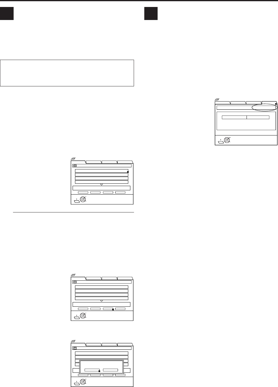
52 EN
Deleting program information
When you want to delete the stored information for each
recorded program, follow the procedure below by using
the Remote.
•Program information for the Video Navigation function
is deleted, but the recorded program will not be erased.
ATTENTION
Once the information is deleted, it is impossible to
restore that information.
1Load a cassette
Insert a tape on which there is a program you want
to edit.
2Access Video Navigation screen
Press NAVI.
3Select program
Press %fi to select the
program you want to
edit, then press OK.
●“*” is displayed beside the tape number of the
loaded cassette.
●The cassette mark is displayed on the left of the
tape title. The items without the cassette marks
are the program titles included in the tape.
●To go to another page of the lists, press < or >.
4Access delete screen
Press
@
#
to move the
arrow to “DELETE”,
then press OK.
5Delete program information
Press
@
#
to move the
highlight bar to “YES”,
then press OK.
6Return to normal screen
Press NAVI.
EChecking memory
You can check the amount of recorded information in
the VCR’s memory.
1Access Video Navigation screen
Press NAVI.
2Access Navigation Set Up screen
Press %fi
@
#
to move the arrow to “NAVI. SET
UP”.
3Check memory
The percentage of the
used memory is
displayed.
4Return to normal screen
Press NAVI.
If memory is full, you have to delete unwanted
information to store more information in the VCR’s
memory.
F
BLANK NAVI. SET UP
SEARCH LIBRARY
1. SYDNEY OLYMPIC
PLAY STOP DELETE EDIT
0107 ALL SPORTS TAPE BLANK 2:00 (LS3) 1 / 3
SELECT
OK
2. FOOTBALL
3. EURO 96 ENGLAND
4. PROJECT XYZ
SYDNEY OLYMPIC [SHOW]
12/21/02 SAT 6:30 AM – 5:53 PM DBS 256CH LS3
SELECT WITH ARROW KEYS
THEN PRESS [OK]
EXIT
NAVI
Navigation
BLANK NAVI. SET UP
SEARCH LIBRARY
1. SYDNEY OLYMPIC
PLAY STOP DELETE EDIT
0107 ALL SPORTS TAPE BLANK 2:00 (LS3) 1 / 3
SELECT
OK
2. FOOTBALL
3. EURO 96 ENGLAND
4. PROJECT XYZ
SYDNEY OLYMPIC [
SHOW]
12/21/02 SAT 6:30 AM – 5:53 PM DBS 256CH LS3
SELECT WITH ARROW KEYS
THEN PRESS [OK]
EXIT
NAVI
Navigation
BLANK NAVI. SET UP
SEARCH LIBRARY
1. SYDNEY OLYMPIC
PLAY STOP DELETE EDIT
0107 ALL SPORTS TAPE BLANK 2:00 (LS3) 1 / 3
SELECT
OK
2. FOOTBALL
3. EURO 96 ENGLAND
4. PROJECT XYZ
SYDNEY OLYMPIC [SHOW]
12/21/02 SAT 6:30 AM – 5:53 PM DBS 256CH LS3
SELECT WITH ARROW KEYS
THEN PRESS [OK]
EXIT
NAVI
Navigation
PROGRAM INFO
DELETE?
NO YES
VIDEO NAVIGATION (cont.)
BLANK NAVI. SET UP
SEARCH LIBRARY
NAVIGATION
NAVIGATION SET UP USED MEMORY 66%
OFF
SELECT
OK
EXIT
NAVI
SELECT WITH ARROW KEYS
THEN PRESS [OK]
Navigation
MV8300_U1B-EN48-52 4/1/3, 2:34 PM52
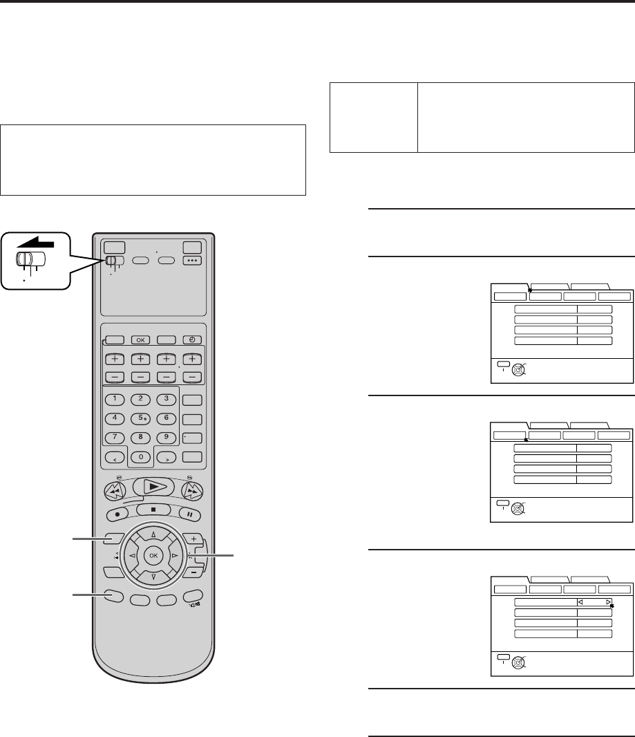
EN 53
VCR
TV
CABLE
/DBS
2 - 5
1 6
BACK
You can use the other useful function settings on the
Function Set Up screens by following the procedure
described below.
The table below shows the structure of the menu system.
●For the functions you can set on the Function Set Up
screen, see pages 54 to 59.
1Access Main Menu screen
Press MENU.
2Access Function Set Up screen
Press
@
#
to move the
arrow to
“FUNCTION SET
UP”, then press fi or
OK.
3Select Function Menu
Press
@
#
to move
the arrow to the
menu of the function
you want to set, then
press fi or OK.
4Select Function
Press %fi to move
the arrow to the
function you want to
set.
5Change setting
Press
@
#
.
6Return to normal screen
Press MENU.
NOTE:
To go back to a previous screen during settings, press BACK.
OTHER USEFUL FUNCTIONS
Useful Function
Settings
FUNCTION
SET UP
VIDEO FUNCTION ( pg. 54)
AUDIO FUNCTION ( pg. 55)
IN/OUT FUNCTION ( pg. 56)
ADDITIONAL ( pg. 57)
FUNCTION SET UP
INITIAL SET UPTUNER SET UP
THEN PRESS [OK]
V. CALIBRATION
PICTURE CONTROL AUTO
ON
ON
DIGITAL R3
VIDEO STABILIZER
VIDEO FUNCTION AUDIO FUNCTION IN/OUT FUNCTION
ADDITIONAL
SELECT WITH ARROW KEYS
SELECT
OK
EXIT
MENU
OFF
FUNCTION SET UP
INITIAL SET UPTUNER SET UP
THEN PRESS [OK]
V. CALIBRATION
PICTURE CONTROL AUTO
ON
ON
DIGITAL R3
VIDEO STABILIZER
VIDEO FUNCTION AUDIO FUNCTION IN/OUT FUNCTION
ADDITIONAL
SELECT WITH ARROW KEYS
SELECT
OK
EXIT
MENU
OFF
FUNCTION SET UP
INITIAL SET UPTUNER SET UP
THEN PRESS [OK]
V. CALIBRATION
PICTURE CONTROL AUTO
ON
ON
DIGITAL R3
VIDEO STABILIZER
VIDEO FUNCTION AUDIO FUNCTION IN/OUT FUNCTION
ADDITIONAL
SELECT WITH ARROW KEYS
SELECT
OK
EXIT
MENU
OFF
●Turn on the VCR and the TV, and select the AV
mode on the TV.
●Set the VCR/TV/CABLE/DBS selector on the
Remote to “VCR”.
MV8300_U1B-EN53-63 4/1/3, 2:33 PM53

54 EN OTHER USEFUL FUNCTIONS (cont.)
* The default setting is bold in the table below.
When this function is set to “ON”, this VCR checks the condition of the
tape in use during playback and recording, and compensates to provide
the highest-possible pictures. This takes place whenever you play back a
tape or start recording after inserting a tape.
NOTES:
●
During playback, this function is always working even though
“VIDEO CALIBRATION” appears just at the beginning of automatic tracking.
●
During recording, this function works only for the first SP recording and the first
EP recording on an inserted tape.
For timer recording, this function checks the tape condition both for the SP
recording and the EP recording before the first timer recording starts.
●
When you play back rental tapes or tapes recorded on other VCRs, set this
function either “ON” or “OFF” whichever gives you the best picture.
PICTURE CONTROL
(S-VHS/VHS only)
AUTO (NORM)
EDIT
SOFT
SHARP
V. CALIBRATION
(S-VHS/VHS only)
ON
OFF
Video settings [VIDEO FUNCTION]
DIGITAL R3 (S-VHS/VHS only)
ON
OFF
This function helps you to adjust the playback picture quality according
to your preference.
AUTO: Normally select this. Picture quality is adjusted
(NORM) automatically.
When “V. CALIBRATION” is “OFF”, “NORM” will appear
instead of “AUTO”. The quality is not adjusted
automatically when “NORM” appears.
EDIT: Minimizes picture degradation during editing (recording
and playback).
SOFT: Reduces image coarseness when viewing overplayed tapes
containing much noise.
SHARP: Clearer, sharper-edged picture when viewing images with
much flat, same-colored surfaces such as cartoons.
NOTES:
●
When you select “EDIT”, “SOFT” or “SHARP”, the selected mode will not
change until you select again.
●
Select “EDIT” when you are editing tapes (
pg. 67). After you finish editing the
tapes, select “AUTO” (“NORM” when “V. CALIBRATION” is “OFF”.)
When this function is set to “ON”, edge correction to the luminance signal
is performed to enhance details. Normally set this function to “ON”.
NOTES:
●
Depending on the type of tape being used, picture quality may be better with
“DIGITAL R3” set to “OFF”.
●
If you use this VCR as the playback VCR for editing, be sure to set “DIGITAL
R3” to “OFF” before starting.
When this function is set to “ON”, you can correct vertical vibrations in
the picture when playing back unstable recordings made on another
VCR.
This function is available only when playing back tapes recorded in EP mode.
NOTES:
●
When you finish viewing a tape, be sure to set this function to “OFF”.
●
Regardless of the setting, this function has no effect during recording and during
special effects playback.
●
To watch recordings with close-caption, set this function to “OFF”.
●
When this function is set to “ON”, the vertical vibrations may occur. Press
CHANNEL + or – on the VCR (or TV/VCR CH + or – on the Remote) to
eliminate vibration.
VIDEO STABILIZER
(S-VHS/VHS only)
ON
OFF
MV8300_U1B-EN53-63 4/1/3, 2:33 PM54
EN 55
* The default setting is bold in the table below.
Up to four audio signal channels can be input from a DV camcorder
through the DV IN connector (i.LINK). This VCR allows you to select
and record two of these channels. This setting is used to specify which
two channels to record.
When there are four DV audio channels (32kHz):
AUDIO1: Records the two channels (L/R) of DV AUDIO 1.
AUDIO2: Records the two channels (L/R) of DV AUDIO 2.
1+2MIX: Mixes and records both DV AUDIO 1 and 2.
When there are two DV audio channels (48kHz):
Because there are only two channels, those two channels are recorded
regardless of the DV sound setting.
DV AUDIO REC
AUDIO1
AUDIO2
1+2MIX
OPTICAL OUT
Dolby D
2CH-PCM
STREAM
Audio settings [AUDIO FUNCTION]
S400
DV IN
D THEATER
REGION 1
i.LINK IN/OUT
DIGITAL OUT
OPTICAL
PCM/DOLBY DIGITAL
R
Y
L
P
B
/C
B
VIDEO
P
R
/C
R
S VIDEO S VIDEO
AUDIO
IN
(L-1)
IN
(L-2)
REMOTE PAUSE/
AV COMPULINK
CABLE BOX
ANTENNA
ANTENNA
OUT
IN
VHF/UHF
RL
VIDEO
AUDIO
OUT IN
COMPONENT
VIDEO OUT
This VCR can send the Dolby Digital bitstream or PCM Audio to external
devices.
When you play back a tape including the Dolby Digital bitstream, and if
you have a device equipped with Dolby Digital decoder, set this
function to “Dolby D”.
If not, set this function to “2CH-PCM”.
“STREAM” will be used when playing back and receiving a audio signals
in other new formats.
When this function is set to “ON”;
●If a SAP program is received, the SAP audio is recorded on both the
normal and Hi-Fi tracks. The main audio is not recorded.
●If a non-SAP program is received, the main audio is recorded on both
the Hi-Fi and normal tracks.
When this function is set to “OFF”, the SAP audio cannot be recorded.
2ND AUDIO REC
ON
OFF
CONTINUED ON NEXT PAGE \
STD AUDIO REC MODE
STANDARD
PCM&STANDARD
You can select the audio format when you record a program or
analog signal from connected devices in STD mode. When this
function is set to “PCM&STANDARD”, you can obtain high-quality
audio sound.
STANDARD: Select this when the picture quality is important
and when you record in MP2 format.
PCM&STANDARD: Select this when the sound quality is important.
When you record the analog signals or DV signals
from the camcorder in STD mode, PCM audio is
also recorded in addition to MP2 audio. In HS
mode, PCM audio is automatically recorded.
Amplifier equipped
with Dolby Digital
decoder
Note for connection:
Remove the protection
cap from the cable.
This VCR
MV8300_U1B-EN53-63 4/1/3, 2:33 PM55

56 EN OTHER USEFUL FUNCTIONS (cont.)
You have to select which terminal — either VIDEO (composite) or S-VIDEO (Y/C
separate signals) to use as the video input terminal on the front panel.
Make sure to select the correct terminal; otherwise, you may fail in recording
(editing) on this VCR.
You have to select which terminal — either VIDEO (composite) or S VIDEO (Y/C
separate signals) to use as the video input terminal (L-1) on the rear panel.
Make sure you select the correct terminal; otherwise, you may fail in recording
(editing) on this VCR.
You have to select which terminal — either VIDEO (composite) or S VIDEO (Y/C
separate signals) to use as the video input terminal (L-2) on the rear panel.
Make sure you select the correct terminal; otherwise, you may fail in recording
(editing) on this VCR.
REAR AUX L-1
VIDEO
S-VIDEO
FRONT AUX F-1
VIDEO
S-VIDEO
REAR AUX L-2
VIDEO
S-VIDEO
TV OUTPUT 1
720to1080
NO CONV.
ALLto480i
Input/Output settings [IN/OUT FUNCTION]
TV OUTPUT 2
WIDE 16:9
NORMAL 4:3
* The default setting is bold in the table below.
Select the apppropriate mode depending on the type of TV you have.
WIDE 16:9: Select this for a wide TV set with 16:9 screen image size.
NORMAL 4:3: Select this for a TV set with 4:3 screen image size.
NOTES:
●
When “TV OUTPUT 2” is set to “WIDE 16:9”, sometimes the screen image may be
stretched vertically.
●
When “TV OUTPUT 2” is set to “NORMAL 4:3”, sometimes subtitles may not be visible
or the ends of the screen image may be cut off. Normally select “WIDE16:9”.
●
In order to let the equipment determine the screen image size, it is recommended that
you connect the VCR and TV using the component video output connectors or S VIDEO
OUT connector.
Select the apppropriate mode when receiving signals via i.LINK connector or
playing back a D-VHS tape containing a recording of an HD (High Definition)
signal:
720to1080: 720p is up-converted to 1080i and output to the TV. 1080i,
480p, and 480i image formats are output to the TV without
being converted. Select this when the 720p image played
back is distorted.
NO CONV.: 1080i, 720p, 480p, and 480i image formats are output to
the TV just as they are.
ALLto480i: All images will be output to the TV in 480i image format.
NOTE:
When you receive signals via i.LINK connector or play back the picture of 1080i, 720p,
480p image format, the signal is not output from the S-VIDEO or VIDEO output connector
if “TV OUTPUT 1” is set to “720to1080” or “NO CONV.”.
MV8300_U1B-EN53-63 4/1/3, 2:33 PM56
EN 57
* The default setting is bold in the table below.
AUTO TIMER
ON
OFF
SUPERIMPOSE
ON
OFF
GRAY BACK
ON
OFF
POWER SAVE
ON
OFF
Additional settings [ADDITIONAL]
When this function is set to “ON”, the VCR automatically switches to EP mode to
allow complete recording if there is not enough tape to record the entire program
while timer-recording in SP mode.
For Example . . .
Recording a program of 140 minutes in length onto a 120-minute tape
Make sure you set this function to “ON” before the timer-recording starts.
NOTES:
●
If you have programed the VCR to timer-record 2 or more programs, the second program and
those thereafter may not fit on the tape with this function set to “ON”. In this case, do not use
this function, but change the recording speed manually during timer programing.
●
In order to ensure that the recording fits on the tape, this function may leave a slight non-
recorded portion at the end of the tape.
●
There may be some noise and sound disturbance where the recording speed switches from SP
to EP mode on the tape.
●
This function is not available during ITR (Instant Timer Recording), and will work properly on
the following tapes: T(ST)-30, T(ST)-60, T(ST)-90, and T(ST)-120.
●When this function is set to “ON”:
The timer recording standby mode is automatically engaged when the VCR is turned
off. It is temporarily canceled when the VCR is turned on. You do not have to press
TIMER (‰) to engage or disengage the timer recording standby mode.
●When this function is set to “OFF”:
You have to press TIMER (‰) to engage or disengage the timer recording standby
mode.
When this function is set to “ON”, various VCR status information (on-screen display)
appears on the screen.
NOTES:
●
When you use this VCR as the playback VCR for editing a tape, be sure to set this function to
“OFF”; otherwise, the VCR status information (on-screen display) will be recorded on the
edited tape.
●
If you select a channel on which no signal is received, the channel number is displayed
regardless of this function setting.
When this function is set to “ON”, the VCR changes the screen into the gray back
screen automatically after/while the input signals do not come into.
When this function is set to “ON”, you can reduce the power consumption. While the
VCR is turned off, the front display panel does not show the clock.
When this function is set to “ON”, an i.LINK device cannot be recognized. As a
result, it is not possible to record a program using the digital tuner’s* timer function.
In addition the device does not pass along data if it is in a branched connection.
* For details of a digital tuner, refer to the instruction manual of the digital tuner.
NOTE:
It takes some time until VCR completes its set up when you turn on the VCR.
AUTO SP = EP TIMER
(S-VHS/VHS only)
ON
OFF
Approximately 110 minutes
SP mode
Approximately 30 minutes
EP mode
CONTINUED ON NEXT PAGE \
MV8300_U1B-EN53-63 4/1/3, 2:33 PM57
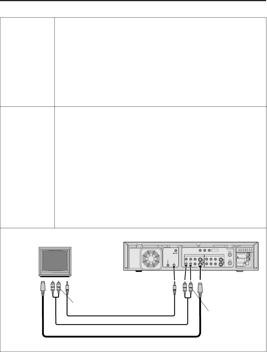
58 EN
S400
DV IN
D THEATER
REGION 1
i.LINK IN/OUT
DIGITAL OUT
OPTICAL
PCM/DOLBY DIGITAL
R
Y
L
P
B
/C
B
VIDEO
P
R
/C
R
S VIDEO S VIDEO
AUDIO
IN
(L-1)
IN
(L-2)
REMOTE PAUSE/
AV COMPULINK
CABLE BOX ANTENNA
ANTENNA
OUT
IN
VHF/UHF
RL
VIDEO
AUDIO
OUT IN
COMPONENT
VIDEO OUT
AV COMPU-LINK
ON
OFF
The REMOTE PAUSE/AV COMPULINK terminal on the rear panel can be used as either
the REMOTE PAUSE terminal or the AV COMPULINK terminal.
When this function is set to “ON”, you can use this terminal as the AV COMPULINK
terminal.
By connecting JVC’s AV COMPULINK components (see the diagram below), including
amplifiers (or receivers) and televisions, one touch control of the audio and video
components linked via their AV COMPULINK connectors becomes possible.
For example: simply load a cassette in the VCR and press PLAY ( 3 ) so that the AV COMPULINK
components automatically turn on, the TV’s AV mode is selected and the VCR starts playback. (You
do not have to press PLAY ( 3 ) if the cassette’s record safety tab is removed.)
When this function is set to “OFF”, you can use this terminal as the REMOTE PAUSE
terminal ( pg. 67).
NOTES:
●
When the remote control code is set to “C” or “D”, the connector cannot be used as AV
COMPULINK terminal even if “AV COMPU-LINK” is set to “ON”. It is recommended to set the
remote control code to “A” when you use this function. (
pg. 71).
●
Connection varies depending on the type of JVC TV you have. Refer to the TV’s instruction manual
when making this connection.
S-VHS MODE
ON
OFF
You can determine which recording mode — either S-VHS mode or VHS mode — is
used for recording on D-VHS and S-VHS tapes.
When this function is set to “ON”, you can record on D-VHS and S-VHS tapes with
S-VHS picture quality.
When this function is set to “OFF”, you can record on D-VHS and
S-VHS tapes with VHS picture quality.
NOTES:
●
To record in S-VHS/VHS mode on D-VHS tape, press D-VHS to turn off the D-VHS indicator.
●
S-VHS mode allows you to make high quality video recordings with horizontal resolution of 400
lines, comparing with the 230 lines of resolution of conventional VHS recordings. To achieve the
highest quality picture we recommend to record in S-VHS mode. (But remember that a
conventional VHS VCR without SQPB cannot play back S-VHS tapes recorded in S-VHS mode.)
●
S-VHS MODE setting does not affect recording on VHS tapes. Recording on VHS tapes is always
performed in VHS mode except when using S-VHS ET mode (
pg. 59).
OTHER USEFUL FUNCTIONS (cont.)
To AV COMPU
LINK II
(VCR ONLY)
AV COMPU LINK
Television
This VCR
To AUDIO
OUT
Mini-plug cable (not supplied)
Audio cable (supplied)
To REMOTE
PAUSE/
AV COMPULINK
To AUDIO IN
To S-VIDEO IN
S-video cable (supplied)
To S VIDEO
OUT
* The default setting is bold in the table below.
MV8300_U1B-EN53-63 4/1/3, 2:33 PM58

EN 59
* The default setting is bold in the table below.
This function allows you to record on VHS tapes with S-VHS picture quality. Tapes
recorded using this function can be played back on a VCR equipped with the S-VHS ET
function. The S-VHS indicator lights up on the front display panel when “S-VHS ET” is set
to “ON”.
NOTES:
●
Before recording, make sure that “V. CALIBRATION” is set to “ON” (
pg. 54).
●
You cannot activate the S-VHS ET function...
–while recording is in progress.
–while timer-recording or Instant Timer Recording (
pg. 28) is in progress.
–while Video Calibration (
pg. 54) is in progress.
●
S-VHS ET does not work with S-VHS tapes.
●
To keep the highest quality recording and playback pictures over a long period of time, S-VHS recording
on S-VHS tapes is recommended.
●
Use of high grade tapes are recommended for S-VHS ET recordings.
On some tapes, picture quality will not improves even if the S-VHS ET function is used. Check the
recording quality before you start important recordings.
●
You can play back S-VHS ET recordings on most of S-VHS VCRs and of VHS VCR equipped with SQPB
(S-VHS QUASI PLAYBACK) function. (Notice some VCRs are not compatible with this function.)
●
While playing back a tape recorded with this function on some tapes, noise may appear. (If playback
picture becomes blurred or interrupted, use a cleaning cassette.)
●
During special effect playback (
pg. 31), noise may appear. If special effect playback is performed
frequently on a tape recorded with this function, the tape may be damaged and picture may be
deteriorated.
S-VHS ET
ON
OFF
DISPLAY
ON
OFF
When this function is set to “OFF”, only “:” appears on the front display panel.
NOTE:
Even if you set “DISPLAY” to “OFF”, each item appears on the front display panel in the following
cases;
●
when the timer-recording is in progress/in the timer standby mode (
pg. 34 – 41)
●
in the satellite Auto Recording standby mode (
pg. 62)
●
during Plug & Play setting (
pg. 9)
●
when you press REC (
) twice for the ITR (
pg. 28)
●
when you set the remote control code (
pg. 71)
●
when you press DISPLAY, the current status appears for a few seconds.
MV8300_U1B-EN53-63 4/1/3, 2:33 PM59
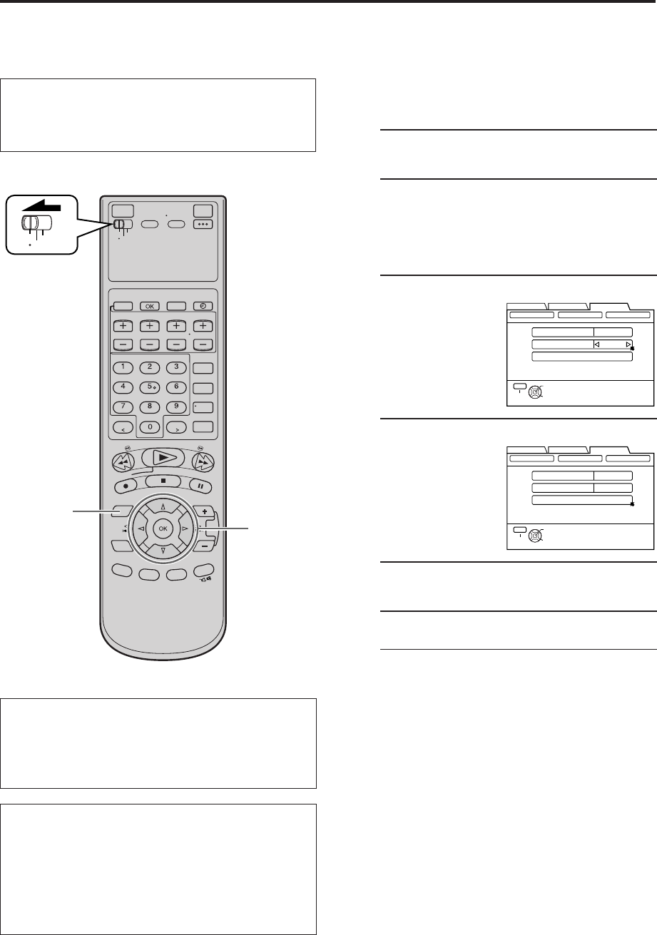
60 EN OTHER USEFUL FUNCTIONS (cont.)
i.LINK Set Up i.LINK set up for connected device
When you connect i.LINK compatible devices to this
VCR, an i.LINK device number is assigned to each
device in the order of connection.
If you want to change the number, follow the procedure
below.
1Access Main Menu screen
Press MENU.
2Access i.LINK Set Up screen
1Press
@ #
to move the arrow to “INITIAL SET
UP”, then press fi or OK.
2Press
@ #
to move the arrow to “OTHER”,
then press fi or OK.
3Confirm LINC setting
Check that “LINC” is
set to “AUTO”. If not,
press %fi to move
the arrow to “LINC”,
then press
@
#
to set
to “AUTO”.
4Reset Number
Press %fi to move
the arrow to “RESET
NUMBER”, then
press OK.
5Return to normal screen
Press MENU.
6Set Number again
Connect the external devices one by one.
•Make sure to connect the VCR's AC power plug
to the AC outlet and turn on the external device
before connection.
•Each device will be numbered in the order of
connection.
NOTES:
●
If you do not want to set i.LINK device number, set “LINC” to
“OFF” in step
3
.
●
You cannot use the i.LINK connection depending on the types
of camcorder equipped with the DV connector. In this case,
set “LINC” to “OFF” in step
3
.
VCR
TV
CABLE
/DBS
2 - 4
1 5
FUNCTION SET UP
INITIAL SET UPTUNER SET UP
THEN PRESS [OK]
CLOCK SET
JLIP ID
LINC
RESET NUMBER
1
GUIDE CHANNEL OTHER
SELECT WITH ARROW KEYS
AUTO
SELECT
OK
EXIT
MENU
FUNCTION SET UP
INITIAL SET UPTUNER SET UP
THEN PRESS [OK]
CLOCK SET
JLIP ID
LINC
RESET NUMBER
1
GUIDE CHANNEL OTHER
SELECT WITH ARROW KEYS
AUTO
SELECT
OK
EXIT
MENU
●Turn on the VCR and the TV, and select the AV
mode on the TV.
●Set the VCR/TV/CABLE/DBS selector on the
Remote to “VCR”.
ATTENTION
If the i.LINK setting does not work, press D-VHS and
STOP/EJECT ( 7/0 ) simultaneously for more than 5
seconds to reset the settings. The cassette is automatically
ejected.
LINC
You can control one of the i.LINK-compatible devices
connected to this VCR with the i.LINK cable. “LINC”
means to select one of the connected devices. After
establishing a LINC with an i.LINK-compatible device,
you're ready to control the i.LINK device.
LINC (Logical Interface Connection) involves establishing a
logical connection, as the abbreviation implies.
MV8300_U1B-EN53-63 4/1/3, 2:33 PM60
EN 61
What is “i.LINK”?
“i.LINK” is a digital serial interface that allows devices
equipped with an i.LINK connector to exchange digital
video signals, digital audio signals, and device control
signals bi-directionally over a single cable.
i.Link refers to the IEEE1394-1995 industry specification and
extensions thereof. The logo is used for products compliant
with the i.Link standard.
This VCR uses a four-pin i.LINK connector to input and
output MPEG2 video signals, audio signals, and control
signals. The i.LINK connector is also used as an input for
DV compressed signals from the DV output of a digital
video camera.
i.LINK Connection
i.LINK-compatible devices can be connected in daisy
chain fashion using i.LINK cables.
Any two devices in the daisy chain can exchange data
bi-directionally, even if there are other devices
connected between them.
i.LINK also supports a “repeater function” that passes
input MPEG2 and DV signals through to the next device
in the chain.
i.LINK Branched Connection
If you are connecting a device that is equipped with
three or more i.LINK connectors, you can also branch
the i.LINK connection.
A B C D
A to D: i.LINK-compatible
devices
i.LINK cable
A B C D
E F
i.LINK cable
A to F: i.LINK-compatible devices
B, C: Devices with three or more i.LINK connectors
A B C D
A B C
A B
Good connection examples
(A to D: i.LINK-compatible devices)
The connections below do not form a loop.
Bad connection examples
(A to D: i.LINK-compatible devices)
The connections below form a loop.
A B C D
A B C
A B
C: Device with three i.LINK connectors
NOTES:
●
You can connect as many as 63 devices (including this VCR) through an i.LINK connection. If you use a branched i.LINK
connection, however, the maximum path length on a branch is 17 devices.
●
In the case of a personal computer and some other devices, data is not passed along by those devices if the device power is off.
For details, refer to the instruction manual for the connected device.
Furthermore, data is not passed along by this VCR when "POWER SAVE" is set to "ON" on this VCR (
pg. 57) and the VCR is
turned off.
●
The maximum data transfer speed supported by the i.LINK connector on this VCR is 400Mbps (approximately 400 megabits per
second). The maximum data transfer speed that is actually attained may be slower depending on how this VCR is used or if a
device with a slower transfer speed is connected to this VCR.
●
Use the S400 i.LINK cable.
i.LINK Connection Examples
Examples of good i.LINK connections and bad i.LINK
connections are shown below. The digital signals flow to
all connected devices. When connecting i.LINK devices,
make sure that the devices are connected in such a way
that digital signals do not return (loop back) to the device
that output them. Looped connection is not permitted.
MV8300_U1B-EN53-63 4/1/3, 2:33 PM61
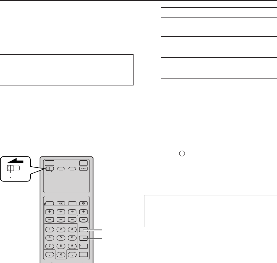
62 EN OTHER USEFUL FUNCTIONS (cont.)
NOTES:
●
While the Satellite Auto Recording standby mode or after Satellite Auto Recording is finished, the VCR will not enter the timer
recording standby mode even though “AUTO TIMER” is set to “ON” (
pg. 57).
●
If you turn off this VCR while Satellite Auto Recording is in progress, recording stops.
●
Video Calibration (
pg. 54) does not work while Satellite Auto Recording is in progress.
●
Auto Clock (
pg. 11) does not work while in the Satellite Auto Recording standby mode.
●
The VCR may not record a short portion at the beginning of the program or may record slightly longer than the actual length of the
program when Satellite Auto Recording method is used.
●
If you engage the Satellite Auto Recording standby mode while the DBS receiver is turned on, the VCR will not start Satellite Auto
Recording, and “L-1” and “
‰
” blink on the front display panel. When you turn off the DBS receiver, “L-1” and “
‰
” light up and
the VCR enters the Satellite Auto Recording standby mode.
●
If you have connected another component other than a DBS receiver (or cable box) to the AUDIO/VIDEO IN or S VIDEO IN (L-1)
connectors, be sure not to engage the Satellite Auto Recording standby mode; otherwise, the VCR will start recording when the
connected component is turned on.
●
Satellite Auto Recording and timer-recording cannot be performed at the same time.
●
If the “L-1” blinks quickly on the front display panel in the Satellite Auto Recording standby mode (even though your DBS receiver
is turned off), Satellite Auto Recording will not work properly.
If this is the case, perform “Express Timer Programing” (
pg. 38) to timer-record a satellite program.
(Some DBS receivers output signals even if the power is off. Satellite Auto Recording is not possible with those DBS receivers.)
This function allows you to automatically record a
satellite program which is timer-programed on your DBS
receiver.
Preparation: Connect a DBS receiver to the AUDIO/
VIDEO IN or S VIDEO IN (L-1) connectors* on the rear;
otherwise, you cannot use this function.
•You can also connect the cable box if it has a timer.
*
To use these connectors, you have to select which one to use
(
pg. 56).
Satellite Auto
Recording
1Set timer program on DBS receiver
•For timer programing method, refer to the
manual supplied with the DBS receiver.
2Load a cassette
Make sure the record safety tab is intact.
3Set recording speed
Press REC SPEED to set the recording speed.
4Engage Satellite Auto Recording standby
mode
Turn off the DBS receiver.
Press and hold REC LINK on the Remote for more
than 2 seconds.
The VCR turns off automatically and the “L-1”
and “‰” appears on the front display panel
(Satellite Auto Recording standby mode).
When the DBS receiver outputs a signal, the VCR
starts recording and the “L-1” blinks and the
record ( ) indicator lights. The VCR stops
recording and powers off when the DBS receiver
stops outputting a signal.
•Each time you press the button, Satellite Auto
Recording standby mode turns on and off.
When it is off, “L-1” disappears.
IMPORTANT: Be sure not to turn on the DBS receiver
before the program starts broadcasting; otherwise, the
VCR will start recording when the DBS receiver is
turned on.
VCR
TV
CABLE
/DBS
4
3
●Turn on the VCR and the TV, and select the AV
mode on the TV.
●Set the VCR/TV/CABLE/DBS selector on the
Remote to “VCR”.
MV8300_U1B-EN53-63 4/1/3, 2:33 PM62
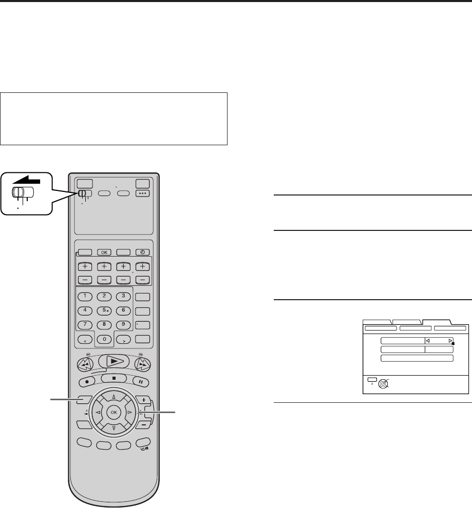
EN 63
JLIP ID Number
Setting
The JLIP (Joint Level Interface Protocol) terminal is used
to connect the VCR to a personal computer or similar
device. By connecting through the JLIP terminals, you
can control the VCR during editing and certain other
operations, from the connected personal computer or
similar device.
When connecting this VCR to another device using the
JLIP terminals, each device must have a different JLIP ID
number.
The JLIP ID number of this VCR is preset to “1” when
shipped from the factory. You can change this number to
any other number between 1 to 99.
To change the JLIP ID number of this VCR, follow the
procedure below.
1Access Main Menu screen
Press MENU.
2Select JLIP ID Set Up screen
1Press
@ #
to move the arrow to “INITIAL SET
UP”, then press fi or OK.
2Press
@ #
to move the arrow to “OTHER”,
then press fi or OK.
3Set JLIP ID Number
Press %fi to move
the arrow to
“JLIP ID”.
Press
@ #
to enter the
desired ID number.
4Return to normal screen
Press MENU.
NOTE:
For further details on the JLIP system, consult your Marantz
authorized dealer or visit our website www.marantz.com.
VCR
TV
CABLE
/DBS
1 4 2 3
FUNCTION SET UP
INITIAL SET UPTUNER SET UP
THEN PRESS [OK]
CLOCK SET
JLIP ID
LINC
RESET NUMBER
1
GUIDE CHANNEL OTHER
SELECT WITH ARROW KEYS
AUTO
SELECT
OK
EXIT
MENU
●Turn on the VCR and the TV, and select the AV
mode on the TV.
●Set the VCR/TV/CABLE/DBS selector on the
Remote to “VCR”.
MV8300_U1B-EN53-63 4/1/3, 2:33 PM63
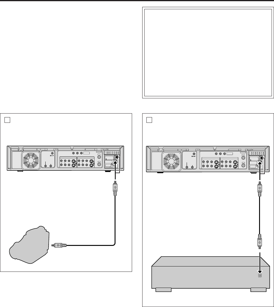
64 EN
i.LINK/DV
Connections
EDITING
S400
DV IN
D THEATER
REGION 1
i.LINK IN/OUT
DIGITAL OUT
OPTICAL
PCM/DOLBY DIGITAL
R
Y
L
P
B
/C
B
VIDEO
P
R
/C
R
S VIDEO S VIDEO
AUDIO
IN
(L-1)
IN
(L-2)
REMOTE PAUSE/
AV COMPULINK
CABLE BOX
ANTENNA
ANTENNA
OUT
IN
VHF/UHF
RL
VIDEO
AUDIO
OUT IN
COMPONENT
VIDEO OUT
A
This VCR supports the copy protection technologies
of DTLA (Digital Transmission Licensing
Administrator). These technologies are admitted by
DTLA (Digital Transmission Licensing
Administrator).
It is impossible to dub copy-limited signals between
the devices which supports copy protection
technologies of DTLA. It is impossible to dub to
other tapes the program which only one recording
is permitted.
When connecting to other devices, only the
operation of the devices which supports DTLA is
guaranteed. The operation of non-DTLA-supported
devices is not guaranteed.
To DV output
This VCR (for recording)
To DV IN
connector
DV cable
(not supplied)
DV camcorder
(for playback)
S400
DV IN
D THEATER
REGION 1
i.LINK IN/OUT
DIGITAL OUT
OPTICAL
PCM/DOLBY DIGITAL
R
Y
L
P
B
/C
B
VIDEO
P
R
/C
R
S VIDEO S VIDEO
AUDIO
IN
(L-1)
IN
(L-2)
REMOTE PAUSE/
AV COMPULINK
CABLE BOX
ANTENNA
ANTENNA
OUT
IN
VHF/UHF
RL
VIDEO
AUDIO
OUT IN
COMPONENT
VIDEO OUT
B
To i.LINK IN/
OUT connector
This VCR (for recording)
To i.LINK IN/
OUT connector
i.LINK cable
(not supplied)
Another VCR (for playback)
NOTES:
●
You cannot use the i.LINK connection depending on the type
of camcorder equipped with the DV connector. In this case,
set “LINC” to “OFF” (
pg. 60)
●
If the 44.1 kHz PCM audio signal is input via DV connector,
recording cannot be performed properly.
You can use a camcorder as the playback device and
your VCR as the recording VCR.
You can use your VCR as the playback or recording
VCR.
Ex. When using this VCR as the recording VCR
MV8300_U1B-EN64-71 4/1/3, 2:31 PM64
EN 65
1Make connections
A Connection with the camcorder
Connect a DV cable between the camcorder’s
DV connector and your VCR’s DV IN connector.
B Connection with the VCR
Connect an i.LINK cable between the playback
VCR’s i.LINK input/output connector and the
recording VCR’s i.LINK input/output connector.
NOTES:
●
Depending on the devices equipped with the i.LINK
connector which is connected to the VCR, picture
noise on this VCR may differ from the noise on the
connected devices. It is caused by the difference of
the data processing method.
●
Connection with certain product(s) may not be
supported. (
“ATTENTION” on the back cover.)
2Load a cassette
Insert the cassette to be recorded on into this
VCR (for recording).
3Select input location on this VCR
On the front panel:
Press CHANNEL +/– to select "I-1 etc.".
On the Remote:
Press TV/VCR CH +/– to select "I-1 etc.".
4Set recording speed
Press REC SPEED to set the recording speed.
●For more details, refer to "About Recording
Speed" below.
5Start playback
Press PLAY ( 3 ) on the connected device.
NOTE:
If the connected device is equipped with a
superimpose/OSD disable feature then set it to “OFF”
before starting playback.
6Start recording
On the front panel:
Press REC ( ¶ ).
On the Remote:
Press REC ( ¶ ) and PLAY ( 3 ) at the same time.
NOTE:
If "108 REC BY HS MODE" appears on the TV screen, refer to
"Error Codes and Messages" on page 77.
Do not connect this VCR to the PC with the i.LINK
cable. The operation is not guaranteed.
About Recording Speed
* Auto mode: The recording speed will be selected automatically according to the amount of data input (the transfer rate) from
the i.LINK connector.
NOTES:
●
When dubbing using the i.LINK connector, set the recording speed on the recording VCR to the same speed as the source tape
on the playback VCR.
●
When "AUTO" is selected for the recording speed, "AUTO" and the selected speed appear on the front display panel in turn.
Input Source
(Playback device)
i.Link/
D-VHS
DV input DV camcorder
Others
Selectable Recording Speed
(Recording device: This VCR)
Auto (HS/STD/LS3/LS5)*, HS, STD, LS3, LS5
HS, STD, LS3, LS5
Auto (HS/STD)*, HS
MV8300_U1B-EN64-71 4/1/3, 2:31 PM65
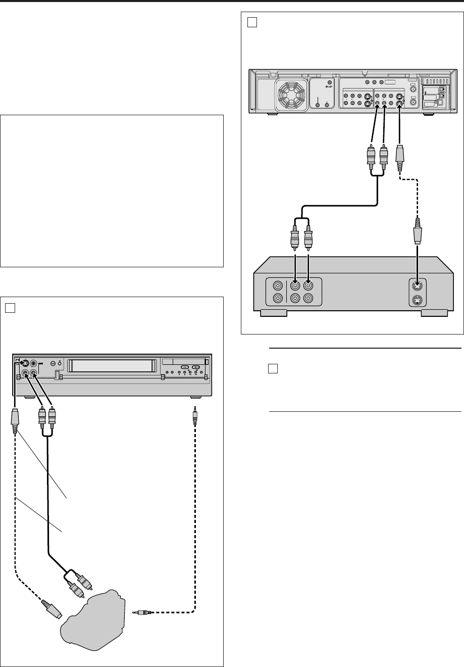
66 EN
S400
DV IN
D THEATER
REGION 1
i.LINK IN/OUT
DIGITAL OUT
OPTICAL
PCM/DOLBY DIGITAL
R
Y
L
P
B
/C
B
VIDEO
P
R
/C
R
S VIDEO S VIDEO
AUDIO
IN
(L-1)
IN
(L-2)
REMOTE PAUSE/
AV COMPULINK
CABLE BOX
ANTENNA
ANTENNA
OUT
IN
VHF/UHF
RL
VIDEO
AUDIO
OUT IN
COMPONENT
VIDEO OUT
S-VIDEO/
VIDEO
Connections
EDITING (cont.)
B
1Make connections
A Connection with the camcorder
Connect an audio/S-video cable between the
camcorder’s audio/S-video output connectors
and your VCR’s audio/S-video input connectors.
●When the JVC camcorder is equipped with the
Master Edit Control, you can control the VCR
from the camcorder. Connect the mini-plug
cable (not supplied with this VCR) as
illustrated on the left.
●When using a camcorder with a monaural
output, connect the audio output connector on
the camcorder to the left audio input
connector on this VCR.
NOTE:
If the camcorder does not have S-video output
connector, use a video cable.
Another VCR (for playback)
Audio cable
(supplied)
This VCR (for recording)
To AUDIO
OUT
To Audio
Input
To S VIDEO
OUT
To S-video
Input
S-video
cable
(supplied)
IN F-1
+
A
To rear panel
REMOTE PAUSE/
AV COMPULINK
connector
Mini-plug cable
(not supplied)
(JVC camcorder
only)
Audio cable
(supplied)
Camcorder
(for playback)
To Audio output
To EDIT
This VCR (for recording)
To AUDIO
Input
S-video cable
(supplied)
To S-video
output
To S-VIDEO
Input
Various connection for editing tapes
The following three methods can be used for editing tapes.
●
VHS to S-VHS editing (VIDEO-VIDEO connection):
Although the picture quality is inherently limited by the
original VHS quality, the edited tape has better picture
quality than those made by VHS-to-VHS editing.
●
S-VHS to VHS editing (VIDEO-VIDEO connection):
Since the original source is recorded in S-VHS mode, the
edited tape has better picture quality than those made by
VHS-to-VHS editing.
●
S-VHS to S-VHS editing (S-VIDEO connection): Original
picture quality of S-VHS made can be duplicated with
minimal picture degradation. This is the best editing
method you can use on S-VHS VCRs.
You can use a camcorder as the playback device and
your VCR as the recording VCR.
You can use your VCR as the playback or recording
VCR.
Ex. When using this VCR as the recording VCR
MV8300_U1B-EN64-71 4/1/3, 2:31 PM66
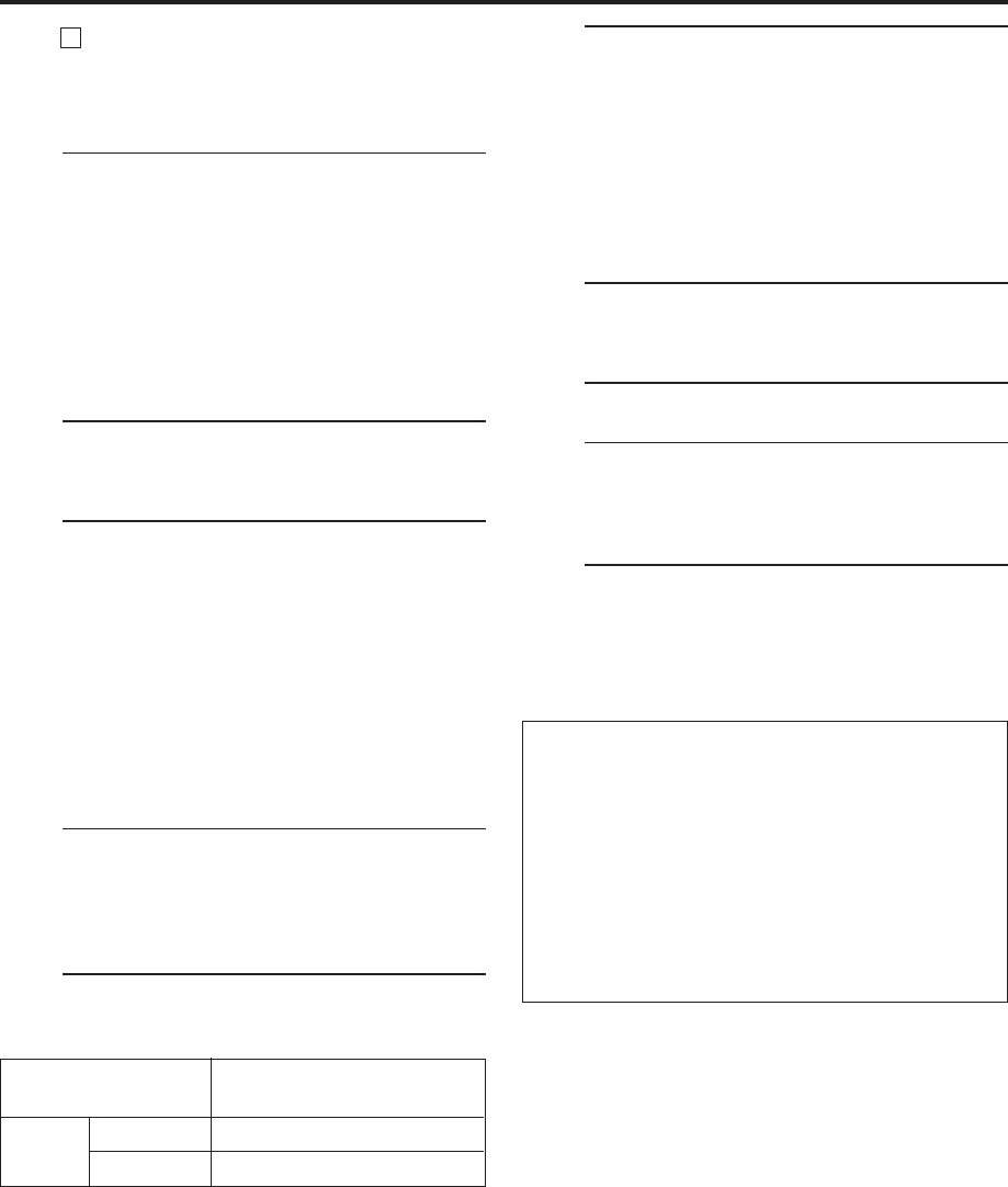
EN 67
5Select video input terminal
Access the “IN/OUT FUNCTION” screen
( pg. 56).
When using S VIDEO terminal, set “FRONT AUX
F-1” (or “REAR AUX L-1 (or L-2)” if you use the
connectors on the rear) to “S-VIDEO”.
When using VIDEO terminal, set “FRONT AUX
F-1” (or “REAR AUX L-1 (or L-2)” if you use the
connectors on the rear) to “VIDEO”.
6Set “PICTURE CONTROL” to “EDIT”
Access the “VIDEO FUNCTION” screen
( pg. 54).
7Start playback
Press PLAY ( 3 ) on the connected device.
NOTE:
If the connected device is equipped with a
superimpose/OSD disable feature then set it to “OFF”
before starting playback.
8Start recording
On the front panel:
Press REC ( ¶ ).
On the Remote:
Press REC ( ¶ ) and PLAY ( 3 ) at the same time.
To use a Master Edit Control-equipped JVC
camcorder
1Access the “ADDITIONAL” screen ( pg. 57),
then set “AV COMPU-LINK” to “OFF” after
performing step 6.
●The REMOTE PAUSE/AV COMPULINK connector
works as a Remote Pause connector when “AV
COMPU-LINK” is set to “OFF”.
●For details, refer to the camcorder’s instruction
manual.
2Engage the VCR’s recording pause mode.
NOTES:
●
Be sure to select “AUTO” for “PICTURE CONTROL” (or
“NORM” when “V. CALIBRATION” is set to “OFF”) after you
finish dubbing the tapes (
pg. 54).
●
It is impossible to perform dubbing properly only with an
audio cable. Connect also the video or S-video cable.
Input Source
(Playback device)
Analog D-VHS
input S-VHS/VHS
Selectable Recording Speed
(Recording device: This VCR)
HS, STD, LS3, LS5
SP, EP
B Connection with the VCR
Connect an audio/S-video cable between the
playback VCR’s audio/S-video output connectors
and the recording VCR’s audio/S-video input
connectors.
●When using this VCR as the recording VCR,
connect this VCR’s audio/S-video input
connectors to the audio/S-video output
connectors on the other VCR.
If the playback VCR is monaural, connect the
audio output connector on the playback VCR to
the left audio input connector on this VCR.
NOTE:
If another VCR does not have S-video input/output
connectors, use a video cable.
2Load a cassette
Insert the cassette to be recorded on into this
VCR (for recording).
3Select input location on this VCR
L-1 or L-2 —when connecting the device to the
audio/video or audio/S-video input
connectors on the rear panel.
F-1 —when connecting the device to the
audio/video or audio/S-video input
connectors on the front panel.
On the front panel:
Press CHANNEL +/–.
On the Remote:
Press the Number key “0 (AUX)” or
TV/VCR CH +/–.
NOTES:
●
When using this VCR as the recording VCR, set the
video input terminal setting correctly (
pg. 56).
●
When using this VCR as the playback VCR for
editing, set “DIGITAL R3” to “OFF” (
pg. 54).
4Set recording speed
Press REC SPEED to set the tape speed.
MV8300_U1B-EN64-71 4/1/3, 2:31 PM67
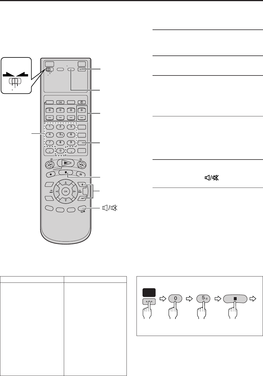
68 EN
VCR
TV
CABLE
/DBS
2
TV/VCR
TV VOL
+/–
ENTER
4
3
- 3
3
- 2
4
Number keys
3
- 1,
3
4
MULTI-BRAND REMOTE CONTROL
When programed (set) with a manufacturer’s (brand’s)
code, this Remote can perform some of the remote
control functions of the listed TVs.
1Turn on the TV
Turn on the TV using the Power button on the TV
or its Remote.
2Set remote operation mode
Set the VCR/TV/CABLE/DBS selector to “TV”.
3Set TV brand code
Follow the example shown below.
1Press and hold POWER.
2Press the Number keys to enter your TV’s
brand code by referring to the table below.
3Press STOP ( 7 ), and release POWER.
●Once you have set the Remote to operate a TV,
you do not have to set it again until you replace
the Remote’s batteries.
●JVC and PANASONIC have two codes. If the
TV does not function with one code, try
entering the other.
4Operate TV
Press one of the following buttons: POWER, TV/
VCR, TV/VCR CH +/–, (TV Muting), TV
VOL +/–, and Number keys.
●For some brands, you must press ENTER after
having pressed the Number keys to enter a
channel number.
●To operate the VCR, set the VCR/TV/CABLE/
DBS selector back to “VCR”.
NOTES:
●
Depending on the type of TV, some or all functions cannot be
operated using this Remote.
●
It is impossible to control a TV that does not have a remote
sensor.
TV BRAND NAME BRAND CODE
JVC 01, 03
HITACHI 10
MAGNAVOX 02
MITSUBISHI 03
PANASONIC 04, 11
RCA 05
SHARP 06
SONY 07
SAMSUNG 12
SANYO 13
SEARS 13
TOSHIBA 08
ZENITH 09
TV Brand
Setting
(Ex.) To set Remote to RCA 05:
Press in succession
Hold
down Release
POWER
AUX
JKL
STOP
MV8300_U1B-EN64-71 4/1/3, 2:31 PM68
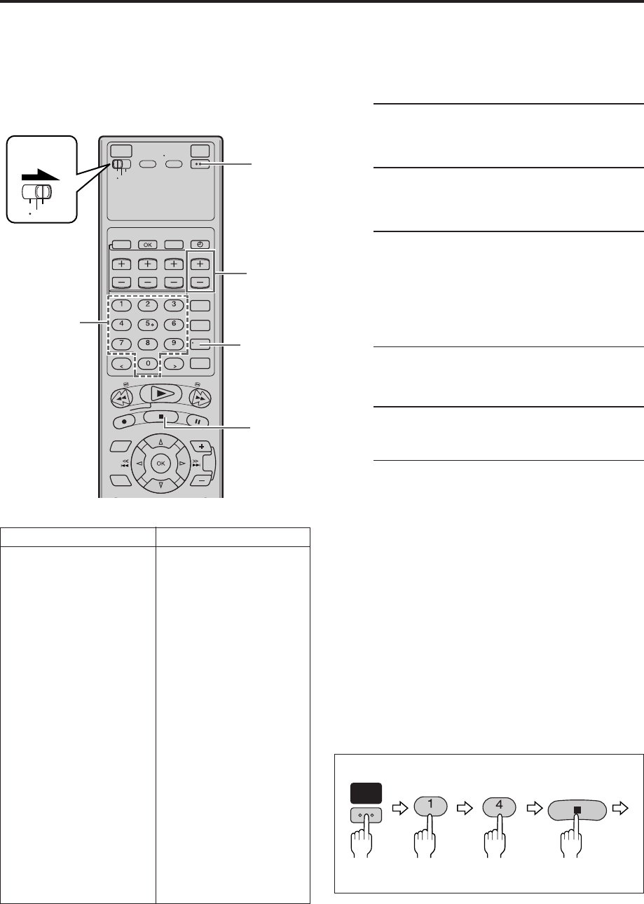
EN 69
When programed (set) with a manufacturer’s (brand’s)
code, this Remote can perform some of the remote
control functions of the listed cable boxes. If your cable
box does not function with a specified code, try other
codes.
1Turn on the cable box
Turn on the cable box using the Power button on
the cable box or its Remote.
2Set remote operation mode
Set the VCR/TV/CABLE/DBS selector to “CABLE/
DBS”.
3Enter cable box brand code
Follow the example shown below.
1Press and hold POWER.
2Press the Number keys to enter your cable
box’s brand code by referring to the table
below.
3Press STOP ( 7 ), and release POWER.
●Once you have set the Remote to operate a
cable box, you do not have to set it again until
you replace the Remote’s batteries.
4Operate cable box
Press one of the following buttons: POWER, TV/
VCR CH +/–, and Number keys.
●For some brands, you must press ENTER after
having pressed the Number keys to enter a
channel number.
●To change the cable box’s channels, press
TV/VCR CH +/– or the Number keys.
●To operate the VCR, set the VCR/TV/CABLE/
DBS selector back to “VCR”.
NOTES:
●
Depending on the type of cable box, some or all functions
cannot be operated using this Remote.
●
It is impossible to control a cable box that does not have a
remote sensor.
●
It’s not possible to set the Remote for both your cable box and
a DBS receiver at the same time. You can only set the Remote
to operate one of these units at a time.
CABLE BOX BRAND NAME BRAND CODE
ARCHER 01, 05, 17
CABLETENNA 01, 17
CABLEVIEW 15, 16, 17, 21, 25
CITIZEN 15, 16, 17, 21, 25
CURTIS 02
DIAMOND 01, 17
GC BRAND 15, 16, 17, 21, 25
GEMINI 15
GENERAL INSTRUMENTS 01, 04, 06, 11, 12, 15, 28
HAMLIN 10, 18, 23
JASCO 15
JERROLD 01, 04, 06, 11, 12, 15, 28
NOVAVISION 02
OAK 07
PANASONIC 13, 14
PULSER 15, 16, 17, 21, 25
RCA 13, 14
REGAL 10, 18, 23
REMBRANDT 01, 16, 17
SAMSUNG 05, 16, 24
SCIENTIFIC ATLANTA 02
SIGMA 07
SL MARX 05, 16, 17, 24, 25
SPRUCER 13, 14
STARGATE 05, 15, 16, 17, 21, 24, 25
TELEVIEW 05, 16, 24
TOCOM 01, 04, 16
UNIKA 01, 17
UNIVERSAL 16, 17, 25
VIDEOWAY 03, 09, 22
ZENITH 03, 09, 22
(Ex.) To set the Remote to RCA 14:
Hold
down Press in succession Release
Cable Box
Brand Setting
POWER
. , ? GHI
STOP
VCR
TV
CABLE
/DBS
2
4
TV/VCR
CH +/–
ENTER
3
- 1,
3
4
3
- 3
3
- 2
4
Number keys
MV8300_U1B-EN64-71 4/1/3, 2:31 PM69
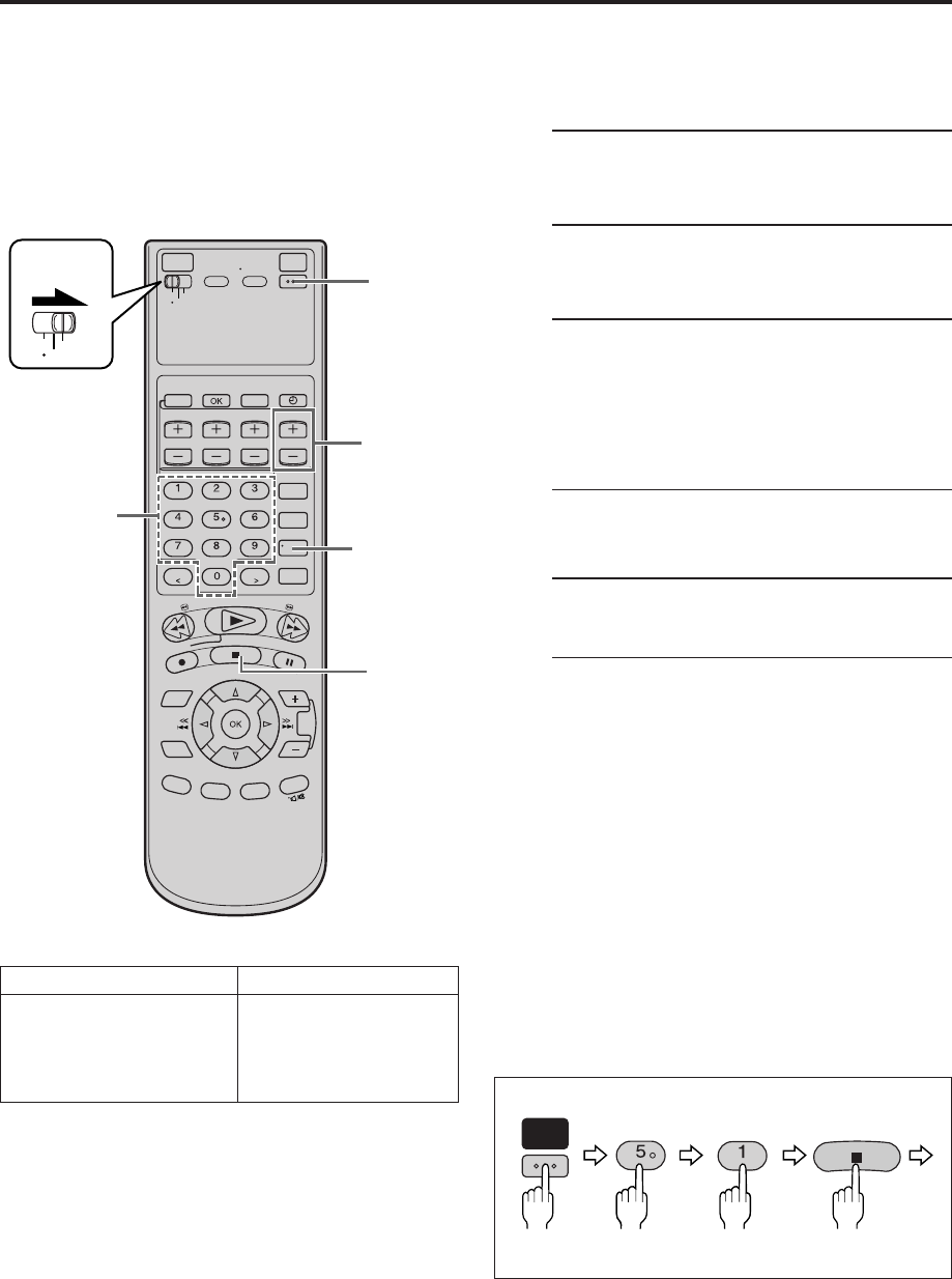
70 EN MULTI-BRAND REMOTE CONTROL (cont.)
When programed (set) with a manufacturer’s (brand’s)
code, this Remote can perform some of the remote
control functions of the listed DBS (Direct Broadcast
Satellite) receivers.
1Turn on the DBS receiver
Turn on the DBS receiver using the Power button
on the DBS receiver or its Remote.
2Set remote operation mode
Set the VCR/TV/CABLE/DBS selector to “CABLE/
DBS”.
3Enter DBS receiver brand code
Follow the example shown below.
1Press and hold POWER.
2Press the Number keys to enter your DBS
receiver’s brand code by referring to the table
below.
3Press STOP ( 7 ), and release POWER.
●Once you have set the Remote to operate a
DBS receiver, you do not have to set it again
until you replace the Remote’s batteries.
4Operate DBS receiver
Press one of the following buttons: POWER, TV/
VCR CH +/–, and Number keys.
●For some brands, you must press ENTER after
having pressed the Number keys to enter a
channel number.
●To change the DBS receiver’s channels, press
TV/VCR CH +/– or the Number keys.
●To operate the VCR, set the VCR/TV/CABLE/
DBS selector back to “VCR”.
NOTES:
●
Depending on the type of DBS receiver, some or all functions
cannot be operated using this Remote.
●
It is impossible to control a DBS receiver that does not have a
remote sensor.
●
It's not possible to set the Remote for both your DBS receiver
and a cable box at the same time. You can only set the
Remote to operate one of these units at a time.
DBS BRAND NAME BRAND CODE
JVC (DISH Network) 51
ECHOSTAR (DISH Network) 51
SONY (DSS) 41
RCA (DSS) 40 (Ex.) To set the Remote to JVC 51:
Release
Hold
down Press in succession
DBS Receiver
Brand Setting
POWER
JKL . , ?
STOP
VCR
TV
CABLE
/DBS
2
4
TV/VCR
CH +/–
ENTER
3 - 1,
3
4
3 - 3
3 - 2 4
Number keys
MV8300_U1B-EN64-71 4/1/3, 2:32 PM70
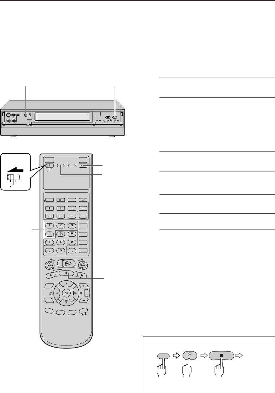
EN 71
The Remote is capable of controlling four JVC video
recorders independently. Each of VCRs can respond to
one of four codes (A, B, C or D).
This Remote control is preset to send A code signals
because your VCR is initially set to respond to A code
signals. You can easily change your Remote and the VCR
to send and respond to B, C or D code signals.
When using four JVC VCRs, set four VCRs and their
Remotes to different codes, so that the Remotes can
operate these VCRs separately.
1Set remote operation mode
Set the VCR/TV/CABLE/DBS selector to “VCR”.
2Set remote control code for Remote
1Press and hold A/B/C/D.
2Press the Number key “1” for A code control
signals, “2” for B code control signals, “3” for
C code control signals, “4” for D code control
signals.
3Press STOP ( 7 ), and release A/B/C/D.
3Turn off VCR
Press POWER on the VCR.
4Check remote control code for VCR
Press PLAY (3) on the VCR for more than 5
seconds.
● The code currently set appears on the front
display panel.
5Turn on VCR
Press POWER on the Remote.
●The code transmitted from the Remote blinks
for a few seconds on the front display panel.
●After the code disappears on the front display
panel, make sure that the VCR is turned on by
pressing POWER on the Remote.
To control four VCRs with the same Remote
You can control four JVC VCRs by switching the remote
control code for the Remote between A, B, C and D
(step 2), keeping four VCRs to different control
codes.
●Press the Number key “1” for A code control signals,
“2” for B code control signals, “3” for C code control
signals, “4” for D code control signals. (To change only
the remote control code for the Remote, DO NOT
perform steps 3 to 5.)
Changing
Remote Control
Code
(Ex.) To set Remote to B code:
Press in succession
Hold
down
Release
A/B/C/D
ABC
STOP
VCR
TV
CABLE
/DBS
2 - 2
2 -
1
5
2 -
3
1
NOTE:
When “POWER SAVE” is set to “ON”, you can not change the
remote control code. Before changing the code, set “POWER
SAVE” to “OFF” (
pg. 57).
IN F-1
+
POWER PLAY (3)
MV8300_U1B-EN64-71 4/1/3, 2:32 PM71
72 EN TROUBLESHOOTING
Before requesting service, use this chart and see if you can repair the trouble yourself. Small problems are often easily
corrected, and this can save you the trouble of sending your VCR off for repair.
POSSIBLE CAUSE
●The AC power cord is disconnected.
●The VCR is in the timer recording
standby mode with “AUTO TIMER”
set to “OFF” ( pg. 57).
●The batteries are discharged.
SYMPTOM
1. The power will not come on.
2. The clock works, but the VCR’s
power will not come on.
3. The Remote will not function.
CORRECTIVE ACTION
Connect the AC power cord.
Press TIMER (‰) to disengage.
Replace the dead batteries with new
ones.
SYMPTOM
1. The cassette gets stuck partway
during loading, and is ejected.
CORRECTIVE ACTION
Make sure the cassette’s window is
facing up, the rear label side is facing
you and the arrow on the front of the
cassette is pointing towards the VCR.
Then insert the cassette.
POSSIBLE CAUSE
●The cassette was inserted incorrectly.
SYMPTOM
1. The tape is running but the picture
will not appear.
2. Breaks are noticeable in Hi-Fi
sound track.
3. The playback picture is blurred or
interrupted, even though TV
broadcasts are clear.
4. The picture stops, or the black or
mosaic noise appears when playing
back a program recorded in D-VHS
mode.
5. The Hi-Fi sound cannot be heard.
6. The D-VHS indicator does not light
up when playing back a D-VHS
cassette.
7. The mosaic noise appears when
receiving the scenes with fast
action or switching the display.
POSSIBLE CAUSE
●The TV receiver is set to the wrong
mode.
●Automatic tracking is engaged.
●The video heads may be dirty.
●The video heads may be dirty.
●The digital program is not recorded
in D-VHS mode.
●Audio Monitor setting is incorrect.
●The program is not recorded in
D-VHS mode.
●This occurs when receiving the
program with the low transfer rate.
CORRECTIVE ACTION
Select the AV mode on the TV.
Disengage auto tracking and adjust
the tracking manually ( pg. 23).
The heads must be cleaned. Use an
optional dry cleaning cassette, or
consult your Marantz authorized
dealer.
The heads must be cleaned. Use an
optional dry cleaning cassette, or
consult your Marantz authorized
dealer.
To record in the D-VHS mode, use a
D-VHS cassette.
Set Audio Monitor to “ L R ”
( pg. 23).
To record the program in D-VHS
mode, press D-VHS so that the
D-VHS indicator lights up, then
perform the recording ( pg. 26).
This noise already appears in the
broadcast station, and this is not a
malfunction of your VCR.
POWER
TAPE TRANSPORT
PLAYBACK
MV8300_U1B-EN72-88 4/1/3, 2:28 PM72
EN 73
CORRECTIVE ACTION
Insert a cassette.
Remove the cassette and cover the
hole with adhesive tape, or load a
cassette on which the record safety
tab is intact.
Select the appropriate channel on the
VCR.
Connect the components correctly
( pg. 64, 66) or check “REAR AUX
L-1 (or L-2)” and “FRONT AUX F-1”
setting ( pg. 56).
Make sure the power to all units is on.
Select the appropriate input location
on the recording VCR.
POSSIBLE CAUSE
●There is no cassette loaded.
●The loaded cassette has had its
record safety tab removed.
●The VCR has been set to “L-1”,
“L-2”, “F-1” or “I-1 etc.” input
location by mistake.
●The components have been
incorrectly connected, or correct
video connector (S VIDEO, VIDEO
or DV) is not selected.
●The power to one or more of the
units has not been turned on.
●The recording VCR’s input location
has been set incorrectly.
SYMPTOM
1. Recording will not start, and
“CASS” blinks on the front display
panel for about 5 seconds.
2. TV broadcasts will not be recorded
properly.
3. Tape-to-tape editing will not work.
RECORDING
CORRECTIVE ACTION
Set the clock and/or timer correctly.
Press TIMER (‰) and check to make
sure that ‰ appears on the front
display panel.
Re-perform the set-up procedures.
Make sure you have compensated for
guide channel and VCR or cable box
channel number mismatches
( pg. 36).
Timer programing cannot be performed
when timer recording is in progress.
Wait until it finishes.
Load a cassette with the record safety
tab intact, or with the hole covered
with adhesive tape.
Remove the cassette and cover its
hole with adhesive tape, or replace it
with a cassette on which the safety
tab is intact.
The program may not have been
recorded in its entirety. Next time be
sure you have enough time on the
tape to record the entire broadcast.
Check the programed data and set
again if necessary, then press TIMER
(‰) again.
Connect the Controller correctly
( pg. 15).
After confirming your cable box’s
input channel number, re-access the
Cable Set Up screen and select the
correct number ( pg. 16).
Make sure the power is on before
timer recording starts.
SYMPTOM
1. Timer recording will not work.
2. Timer programing will not work.
3. “CASS” blinks on the front display
panel.
4. The cassette stops automatically,
and ‰, Q and $ on the front
display panel will not stop
blinking.
5. ‰ blinks for 10 seconds and the
timer mode is disengaged.
6. Cable channels are not automatically
switched during timer recording.
POSSIBLE CAUSE
●The clock and/or the timer have
been set incorrectly.
●The timer is not engaged.
●The VCR has not been set up properly.
●Timer recording is in progress.
●The timer is engaged but there is no
cassette loaded.
●The loaded cassette has had its
record safety tab removed.
●The tape reaches its end during
timer recording.
●TIMER (‰) has been pressed when
there are no programs in memory, or
the timer recording program has not
been set correctly.
●The Controller is not properly
connected to the VCR.
●The input channel selected on the
Cable Set Up screen is incorrect.
●The cable box is turned off.
TIMER RECORDING
CONTINUED ON NEXT PAGE \
MV8300_U1B-EN72-88 4/1/3, 2:28 PM73
74 EN TROUBLESHOOTING (cont.)
CORRECTIVE ACTION
Connect the Controller correctly
( pg. 18).
After confirming your DBS receiver’s
input channel number, re-access the
DBS Receiver Set screen and select
the correct number ( pg. 19).
Set the correct DBS receiver brand
code ( pg. 20).
Make sure the power is on before
timer recording starts.
Set “INPUT CH” to “OFF”
( pg. 16, 19).
Re-perform the Changing VCR Plus+
Setting procedure ( pg. 36).
Wait until a space in memory clears,
or cancel unnecessary program
information ( pg. 40).
SYMPTOM
7. Satellite channels are not
automatically switched during timer
recording.
8. Timer recording begins as
scheduled, but the channel is
always incorrect.
9. You moved, and now VCR Plus+
system does not work properly.
10.“PROGRAM FULL” is displayed on
the screen.
POSSIBLE CAUSE
●The Controller is not properly
connected to the VCR.
●The input channel selected on the
DBS Receiver Set screen is incorrect.
●The VCR is not set correctly to control
the DBS receiver.
●The DBS receiver is turned off.
●Even though you do not use an
external cable box or DBS receiver,
on the Cable Set Up screen or DBS
Receiver Set screen, “INPUT CH” is
set to “ON”.
●The receivable stations in the new
area are received on different
channels than those in the previous
area.
●All 24 programs of the VCR’s timer
memory are used.
TIMER RECORDING
MV8300_U1B-EN72-88 4/1/3, 2:28 PM74
EN 75
VIDEO NAVIGATION
CORRECTIVE ACTION
Tape information cannot be shown if
it has not been recorded on this VCR.
Video Navigation cannot work
correctly on a tape if it has more than
one tape number. If this happens, fast-
forward the tape up to its end, eject it,
and try it again.
It is impossible to search the desired
program which is not recorded on
this VCR using Video Navigation.
Check the remaining memory
( pg. 52). If it is full, delete
unnecessary Video Navigation
information ( pg. 51, 52).
Check the remaining memory
( pg. 52). If it is full, delete
unnecessary Video Navigation
information ( pg. 51, 52).
Set “NAVIGATION” to “ON”
( pg. 43).
For details on the recording time for
Video Navigation, refer to “NOTES”
on page 42.
SYMPTOM
1. Tape information screen does not
appear for the currently inserted
tape.
2. The VCR cannot search for the
desired program.
3. “MEMORY FULL” appears on the
screen when you try to start
recording.
4. The information data for Video
Navigation is not registered.
POSSIBLE CAUSE
●The current tape inserted has not
been recorded on this VCR.
●Two (or more) tape numbers are
recorded on one tape.
●The inserted program is not
recorded on this VCR.
●The VCR’s memory for Video
Navigation is fully recorded.
●The VCR’s memory for Video
Navigation is fully recorded.
●“NAVIGATION” is set to “OFF”.
●The recording time is not enough.
CONTINUED ON NEXT PAGE \
MV8300_U1B-EN72-88 4/1/3, 2:28 PM75
76 EN
ATTENTION
●This VCR contains microcomputers. External electronic noise or interference can cause microcomputer to
malfunction. If the VCR does not operate correctly switch its power off and unplug the AC power cord from the
AC supply. Wait for a while and then plug the power back in. Eject and check the condition of the cassette. If
everything appears normal, you can operate the VCR as usual.
●MARANTZ EXPRESSLY DISCLAIMS ALL WARRANTIES, EXPRESS OR IMPLIED, AND SHALL NOT BE LIABLE
FOR ANY AND ALL DAMAGES, CLAIMS OR LIABILITIES, DIRECT OR INDIRECT, ARISING FROM OR
RELATING TO THE USE OF THIS PRODUCT WITH ANY OTHER PRODUCT, DEVICE, COMPONENT, PART
OR MATERIAL THAT IS NON-CONFORMING OR NON-COMPATIBLE WITH THIS PRODUCT.
●THE i.LINK/DV CONNECTION OF THIS PRODUCT CONFORMS TO IEC61883-1; IEC61883-2; IEC61883-4;
IEEE STD 1394-1995; IEEE STD 1394A-2000; 1394 INTERFACE IMPLEMENTATION GUIDELINE FOR D-VHS
VERSION 1.00 AND DTCP (DIGITAL TRANSMISSION CONTENT PROTECTION) SPECIFICATION VERSION
1.1
(THE “SPECIFICATIONS”). USE OF THIS PRODUCT WITH ANOTHER PRODUCT, DEVICE, COMPONENT,
PART OR MATERIAL THAT IS NOT IN CONFORMITY OR COMPLIANT WITH THE SPECIFICATIONS, OR
THAT IMPLEMENT THE SPECIFICATIONS IN A NON-CONFORMING OR NON-COMPATIBLE MANNER WITH
THIS PRODUCT, MAY NOT BE SUPPORTED AND MAY CAUSE DAMAGE TO OR MALFUNCTION OF THIS
PRODUCT. ANY USE OF THIS PRODUCT WITH A NON-CONFORMING OR NON-COMPATIBLE PRODUCT,
DEVICE, COMPONENT, PART OR OTHER MATERIAL SHALL BE AT THE USER’S SOLE AND EXCLUSIVE RISK.
MOISTURE CONDENSATION
Moisture in the air will condense on the VCR when you move it from a cold place to a warm place, or under
extremely humid conditions—just as water droplets form on the surface of a glass filled with cold liquid. Moisture
condensation on the head drum will cause damage to the tape. In conditions where condensation may occur, keep the
VCR turned on for a few hours to evaporate the moisture before inserting a tape.
ABOUT HEAD CLEANING
Accumulation of dirt and other particles on the video heads may cause the playback picture to become blurred or
interrupted. Be sure to contact your Marantz authorized dealer if such troubles occur.
CORRECTIVE ACTION
If you need the skipped channels,
restore them ( pg. 14).
Press PAUSE ( 8 ) to pause the
recording, change channels, then
press PLAY ( 3 ) to resume recording.
Reset the correct brand codes
(pg. 68 – 70 ).
Select a different host channel during
Semiauto Clock Set ( pg. 11), or
perform Manual Clock Set ( pg. 12).
Unplug the AC power plug once, then
plug it again.
Set it to off.
SYMPTOM
1. When scanning channels, some of
them are skipped over.
2. The channel cannot be changed.
3. The Remote will not operate your
TV or cable box or DBS receiver.
4. Even though Auto or Semiauto
Clock Set has been performed, the
clock is incorrect.
5. “PM” blinks on the front display
panel.
6. The subtitles and the menu screen
are overlapped.
POSSIBLE CAUSE
●Those channels have been preset to
be skipped.
●Recording is in progress.
●The brand codes are set incorrectly.
●The clock setting data received from
the host channel is incorrect.
●The VCR do not work properly.
●The subtitle display on the TV is set
to on.
OTHER PROBLEMS
TROUBLESHOOTING (cont.)
MV8300_U1B-EN72-88 4/1/3, 2:28 PM76

EN 77
Playback of tapes recorded in D-VHS mode
•You may see a mosaic (block) noise, grayed images, or
a still image in cases of excessive distortion caused
when playing back a damaged tape or when the heads
are momentarily dirty.
•It takes a moment after you press PLAY (3) until the
image appears and sound is heard.
•It takes a moment after you switch playback speeds
(when switching from special effect playback to
normal playback, for example) until the image appears
and sound is heard. For a few seconds, the image may
be played back out of synch with the sound.
Searching images on D-VHS tapes
•The images appear frame by frame.
•Block noise may appears on the bottom half of images.
•When the blank portion is reached, a still scene of the
last recorded image is displayed.
The picture stops/There is no sound
•When two or more devices are connected to this VCR
with the i.LINK cable (a camcorder and another
i.LINK-compatible device), do not turn on the
camcorder if you record a program from an another
i.Link-compatible device. Turning on and off the
camcorder may cause momentary still images and loss
of sound.
Image or sound is distorted
•When recording from a camcorder connected to this
VCR with the i.LINK cable, the image or sound may be
distorted. If this occurs, insert a D-VHS cassette in the
VCR and turn off and on the VCR, then start recording
again. If the problem is not fixed, record using the
audio/video input connectors instead of i.LINK
connector.
Recording from camcorders and other devices via
i.LINK connector
•You may see a mosaic (block) noise.
•For scenes with fast action, the image may jitter. This
does not affect recording, which will proceed as usual.
•When you watch the camcorder’s, search images
through this VCR, the block noise may appear.
•When you record audio-dubbed DVC cassettes (tapes
which have four recorded channels), sound may not
be heard for the first few seconds.
•When you eject and insert D-VHS cassettes, the sound
may be interrupted for an instant.
•When you press REC SPEED to switch recording speed,
the sound may be interrupted for an instant.
Incorrect image formatting for wide TVs
•If you have connected two different devices using the
S-video output connectors on the back of the VCR, the
sensing signal for wide TVs may not be output
correctly depending on the connected devices. If this
occurs, use the TV controls to switch the screen size.
The following conditions are product features and do not indicate mechanical problems.
MV8300_U1B-EN72-88 4/1/3, 2:28 PM77

78 EN TROUBLESHOOTING (cont.)
Error Codes and Messages
Some error codes and messages may appear on the TV screen when operating the VCR. Refer to the chart below for
the solution.
102
103
104
105
107
108
200
201
202
203
205
300
301
302
CODE MESSAGE DESCRIPTION
REC PROHIBITED
REC PROHIBITED
CAN NOT DECODE VIDEO OR AUDIO
USE SET TOP BOX OR HDTV TUNER
CAN NOT REC DIGITAL INPUT BY
S-VHS/VHS
CHOOSE ANALOG INPUT
CAN NOT REC DIGITAL INPUT BY
S-VHS/VHS
USE ANALOG TIMER PROGRAMMING
REC BY HS MODE
CAN NOT DECODE VIDEO OR AUDIO
USE SET TOP BOX OR HDTV TUNER
WAIT A MINUTE
CALIBRATING. . .
COPY RESTRICTED PROG OUTPUT
480i VIDEO
COPY RESTRICTED PROG CAN NOT
PLAY BACK
CAN NOT PLAY BACK THIS TAPE
CAN NOT DECODE VIDEO OR AUDIO
USE SET TOP BOX OR HDTV TUNER
TOO MANY i.LINK INSTRUMENTS
READ INST.BOOK
COPY RESTRICTED PROG OUTPUT
480i VIDEO
●An attempt was made to make a D-VHS recording of a program for
which only the analog information is copy protected.
●While making a D-VHS recording of a program, a signal in which
only the analog information is copy protected was input to this VCR.
●An attempt was made to dub a D-VHS recording of a digitally copy
protected program.
●While dubbing a D-VHS recording, digitally copy protected
information was input to this VCR.
●This VCR supports copy protection technologies such as DTLA, and
cannot record programs that employ digital copy protection.
●A signal that is not compatible with this VCR was input.
●Switch to the analog input for recording. (It may be possible to play
back the material if using a digital tuner*, etc.)
●An attempt was made to make an S-VHS/VHS recording of a signal
from an i.LINK device other than a digital tuner*.
●The i.LINK connector on this VCR is intended only for D-VHS
recording. This VCR does not convert a digital signal into an analog
signal for recording. Switch to the analog input for recording.
●An attempt was made to make an S-VHS/VHS recording using the
timer function with “i.LINK” selected on the digital tuner* side.
●The i.LINK connector on this VCR is intended only for D-VHS
recording. This VCR does not convert a digital signal into an analog
signal for recording. Also, it is not possible to make a D-VHS
recording on VHS tape. Switch to the analog input for recording.
●When 720p, 1080i signals are recorded in STD/LS3/LS5 mode, select
HS mode to record program properly.
●An attempt was made to play back a signal that is not supported by
this VCR.
●To play back the signal, use the digital tuner*, etc., that was used to
record the signal.
●Normal playback is being prevented by mosaic noise, etc.
●Wait while the VCR calibrates itself so that it can output a normal
image.
●When playing back a program that was copy protected in 1080i,
720p, or 480p mode, the VCR down-converts to 480i mode for output.
●An attempt was made to play back a tape containing a copy protected
program.
●Even if you record a copy protected program, this VCR cannot play it
back.
●An attempt was made to play back a tape containing an invalid
D-VHS recording.
●A signal format that is not supported by this VCR was input.
●Use a digital tuner*, etc.
●A signal containing too much data was input to the i.LINK connector
on this VCR.
●There are too many devices with i.LINK connectors, such as digital
tuners and digital video cameras, connected to the i.LINK connector
on this VCR. Turn off any devices that are not in use.
●When playing back a program that was copy protected in 1080i,
720p, or 480p mode, the VCR down-converts to 480i mode for output.
* For details of a digital tuner, refer to the instruction manual of the digital tuner.
MV8300_U1B-EN72-88 4/1/3, 2:28 PM78

EN 79
RECORDING
Q. When I pause and then resume a recording, the end
of the recording before the pause is overlapped by
the new recording. Why does this happen?
A. This is normal. It reduces distortion at the pause and
resume points.
. . . . . . . . . . . . . . . . . . . . . . . . . . . . . . . . . . . . . . . . . . . .
Q. Can the VCR indefinitely remain in the recording
pause mode?
A. No. The VCR automatically stops after 5 minutes to
protect the heads. When paused during Instant Timer
Recording (ITR), the VCR shuts off automatically after
5 minutes.
. . . . . . . . . . . . . . . . . . . . . . . . . . . . . . . . . . . . . . . . . . . .
Q. What happens if the tape reaches its end during
recording?
A. The VCR stops, then “”and “#” blink on the front
display panel.
TIMER RECORDING
Q. “ ” and “‰” remain lit on the front display panel.
Is there a problem?
A. No. This is a normal condition for a timer recording
in progress.
. . . . . . . . . . . . . . . . . . . . . . . . . . . . . . . . . . . . . . . . . . . .
Q. Can I program the timer while I’m watching a tape
or a TV broadcast?
A. Yes, but while you are setting the timer you will not
see the tape’s or broadcast program’s picture as it is
replaced by the on-screen menu. (The sound from
the tape or broadcast program will be heard during
the timer setting.)
Questions and answers
PLAYBACK
Q. What happens if the tape reaches its end during
playback or search?
A. The VCR automatically rewinds it to the beginning.
. . . . . . . . . . . . . . . . . . . . . . . . . . . . . . . . . . . . . . . . . . . .
Q. Can the VCR indefinitely remain in still mode?
A. No. It stops automatically after 5 minutes to protect
the heads.
. . . . . . . . . . . . . . . . . . . . . . . . . . . . . . . . . . . . . . . . . . . .
Q. During picture search, still picture playback and
frame-by-frame playback, the picture is
intermittent. What’s the cause?
A. Picture loss occurs when these types of playback are
attempted with a tape recorded in LP mode. Pressing
PLAY ( 3 ) to return to normal playback will restore
the picture.
. . . . . . . . . . . . . . . . . . . . . . . . . . . . . . . . . . . . . . . . . . . .
Q. When returning from variable-speed picture search
to normal playback, the picture is disturbed. Should
I be concerned about this?
A. No, it is normal.
. . . . . . . . . . . . . . . . . . . . . . . . . . . . . . . . . . . . . . . . . . . .
Q. When playing back programs that have been timer-
recorded consecutively (such one program from
8:00 to 9:00 and another one from 9:00 to 10:00),
the picture and sound become momentarily
distorted where the first program ends and the
second program begins. Is this a malfunction?
A. No. This is normal.
. . . . . . . . . . . . . . . . . . . . . . . . . . . . . . . . . . . . . . . . . . . .
Q. Other than preventing further recording, what
effect does removing the safety tab have?
A. It disables marking of index codes and tape numbers
for Video Navigation.
. . . . . . . . . . . . . . . . . . . . . . . . . . . . . . . . . . . . . . . . . . . .
Q. Sometimes, during index search, the VCR cannot
find the program I want to see. Why not?
A. There may be index codes too close together.
. . . . . . . . . . . . . . . . . . . . . . . . . . . . . . . . . . . . . . . . . . . .
Q. During playback, on-screen display sometimes
jitters. Why does this happen?
A. If the condition of the tape being played back is not
good, jittering of the video (including on-screen
display) may occur.
MV8300_U1B-EN72-88 4/1/3, 2:28 PM79

80 EN INDEX
Glossary
Digital Broadcasts and D-VHS
Great changes in the entertainment and media industries
are transforming the way we use VHS, and digital
broadcasting is a good example of what the future holds.
Digital broadcasting now allows more efficient use of the
limited broadcast spectrum besides delivering high-
definition video, outstanding sound quality, multiple
channels, and multiple features.
Meanwhile, VHS has evolved with the advances in
broadcasting in response to the need for continued use
of existing VHS resources and the trend toward digital
broadcasts.
Digital broadcasting is not limited to transmissions of
audio and video content. A variety of other data can be
sent as well. As the means to record all of these digital
signals while supporting playback of the extensive VHS
library of analog tapes, D-VHS was developed.
This VCR is equipped with an MPEG-2 encoder and
decoder (codec) for digital recording and playback of
analog signals.
D-VHS is the key to a smooth transition from analog to
digital formats. This next-generation home video
technology lets us continue to enjoy home video
entertainment as popularized in the last century well into
the next.
Linear PCM Audio
Conventional D-VHS recording uses MPEG-1 Layer 2
compression to record analog audio digitally.
For recording without compression, this VCR also
features PCM recording (pulse code modulation: 48 kHz,
16-bit, 1536 kbps).
Used with high-resolution HS/STD mode, it offers
outstanding high-fidelity recording and playback.
(Recording from audio input alone is not supported.)
Dolby Digital
A form of digital audio coding developed by Dolby
Laboratories to deliver surround sound with 5.1 channels
(front left and right, center, rear left and right, and a
channel for LFE (low-frequency effects).
When you play back a digital tape encoded in Dolby
Digital format, the Dolby Digital bistream is sent from
the DIGITAL OUT OPTICAL connector.
Set “OPTICAL OUT” to “Dolby D” ( pg. 55).
Manufactured under license from Dolby
Laboratories. "Dolby", "Pro Logic", and the double-D
symbol are trademarks of Dolby Laboratories.
Confidential unpublished works. Copyright 1992-
1997 Dolby Laboratories. All rights reserved.
i.LINK
“i.LINK” is a digital serial interface that allows devices
equipped with an i.LINK connector to exchange digital
video signals, digital audio signals, and device control
signals bi-directionally over a single cable.
i.Link refers to the IEEE1394-1995 industry specification and
extensions thereof. The logo is used for products compliant
with the i.Link standard.
MPEG2
Abbreviation for Moving Picture Experts Group, Phase 2.
Unlike previous compression methods, MPEG-2 uses an
extremely efficient compression method that supports
high-definition video. Based on the principle that much
video data remains unchanged from one frame to the
next, predictive coding is performed to eliminate
redundant data.
Specifically, compression is applied between frames
(based on the correlation of frame data) and within
frames (based on DCT, or discrete cosine transform) for
an extremely efficient compression technique.
MV8300_U1B-EN72-88 4/1/3, 2:28 PM80

EN 81
List of terms
This guide serves as a quick way to locate frequently used terms and on-screen display names.
A
Accidental erasure prevention 30
Audio Monitor 23
Auto Daylight Saving Time 11
AUTO SP→ EP TIMER 57
AUTO TIMER 57
Automatic tracking 23
AV COMPU-LINK 58
C
Cable box setting
Brand 16
Input channel 16
Installing Controller 15
Channel No. indication 28
Clock setting
Manual setting 12
Preparations 10
Semiauto setting 11
Clock time 28
Connection 7
Connection to TV 7
Component Video Connection 8
S-VIDEO connection 8
Contents 6
Counter reset 22, 85
D
DBS receiver setting
Brand 19
Input channel 19
Installing Controller 18
DIGITAL R3 54
DISPLAY 59
DV AUDIO REC 55
E
Editing
i.LINK/DV Connections 64
Remote Pause function 58
S-VIDEO/VIDEO Connections 66
Express timer programing 38
F
FRONT AUX F-1 56
G
GRAY BACK 57
Guide channel 36
Glossary 80
H
Host channel 9
I
Index
Front display panel 84
Front panel 82
Rear panel 83
Remote 86
On-screen display 85
Index Search 24
Instant Timer Recording (ITR) 28
i.LINK Setting 60
J
JLIP ID Number Setting 63
M
Manual tracking 23
Multi-Brand Remote
Controlling four JVC VCRs 71
Setting Cable Box brand 69
Setting DBS receiver brand 70
Setting TV brand 68
N
Next Function Memory 24
O
On-screen display 29, 85
OPTICAL OUT 55
P
PBS channel 9
PICTURE CONTROL 54
Playback 21
Plug & Play 9
POWER SAVE 57
R
REAR AUX L-1 56
REAR AUX L-2 56
Recording
D-VHS Recording 26
S-VHS/VHS Recording 27
Recording speed 26, 27, 65
Repeat playback 22
S
Satellite Auto Recording 62
Skip Search 24
Special effect playback
Frame-by-Frame Playback 32
High-Speed Picture Search 31
Picture Search 31
Slow Motion Playback 33
Still Picture Playback 32
Variable-Speed Picture Search 31
Specifications 87
STD AUDIO REC MODE 55
SUPERIMPOSE 57
S-VHS ET 59
S-VHS MODE 58
T
Tape position indicator 22
Tape remaining time 85
Time counter 22, 85
Time zone selection 11
Timer recording
Canceling 40
Changing 40
Checking 40
Express 38
Guide channel setting 36
Overlap 41
VCR Plus+ 34
Tracking 23
Troubleshooting 72
Tuner setting
Adding channels 14
Auto Channel Set 13
Manual Channel Set 14
Skipping channels 14
TV OUTPUT 1 56
TV OUTPUT 2 56
V
VCR Plus+ Setting 36
VCR Plus+ Timer programing 34
V. CALIBRATION 54
Video Navigation
Checking memory 52
Editing titles 48
Finding tapes 44
Playback 42
VIDEO STABILIZER 54
2ND AUDIO REC 55
MV8300_U1B-EN72-88 4/1/3, 2:28 PM81
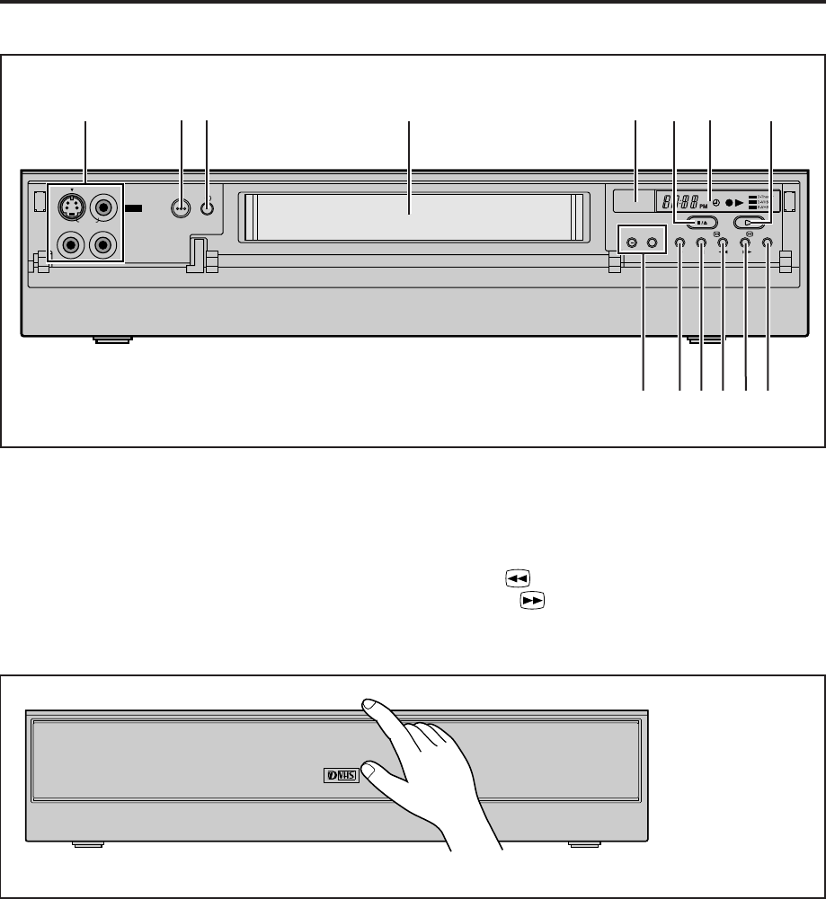
82 EN INDEX (cont.)
Front panel
To access covered buttons/connectors, pull and open the cover.
1S-VIDEO/VIDEO/AUDIO input connectors (F-1)
: pg. 66
2POWER button : pg. 21, 27
3TIMER ‰ button : pg. 35, 39, 40
4Cassette loading slot
5Remote sensor
6STOP/EJECT ( 7/0 ) button : pg. 21, 27
7Front display panel : pg. 84
MENU
S-VIDEO VIDEO
(MONO) L—AUDIO—R
TIMER
— CHANNEL + REC PAUSE REW FF D-VHS
IN F-1
+
STOP/
EJECT
PLAY
1 2 3 4 65 78
@#$! 90
8PLAY ( 3 ) button : pg. 21
9CHANNEL + and – buttons : pg. 23, 26, 27
0REC ( ¶ ) button : pg. 26, 27
!PAUSE ( 8 ) button : pg. 27, 32
@REW ( 1 ) button : pg. 21, 31
#FF ( ¡ ) button : pg. 21, 31
$D-VHS button : pg. 27
MV8300_U1B-EN72-88 4/1/3, 2:28 PM82
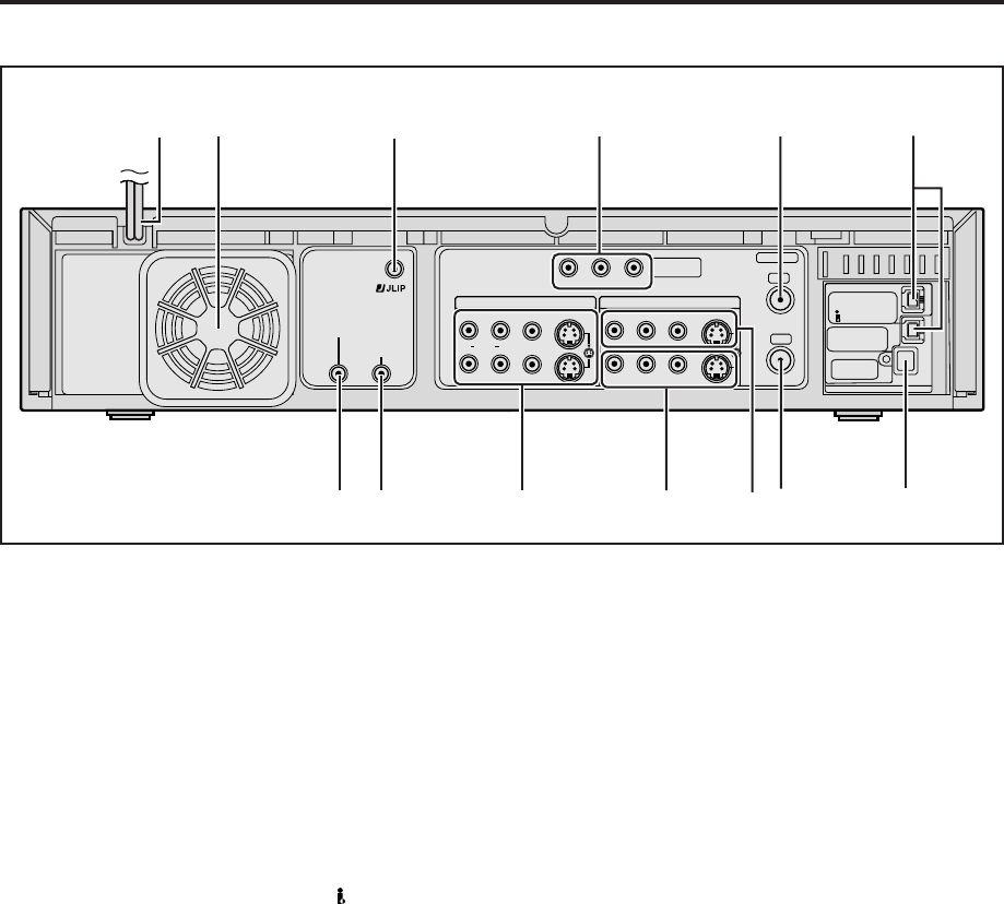
EN 83
Rear panel
1AC power cord : pg. 7
2Cooling fan
● This prevents the temperature from rising inside the
VCR. Do not remove it.
● Install the VCR so as not to block the area around
the cooling fan.
3JLIP terminal : pg. 63
4Component video output connectors : pg. 8
5ANTENNA IN terminal : pg. 7
6i.LINK IN/OUT, DV IN Connector (i.Link*) :
pg. 64
* i.Link refers to the IEEE1394-1995 industry specifi-
cation and extensions thereof. The logo is used for
products compliant with the i.Link standard.
S400
DV IN
D THEATER
REGION 1
i.LINK IN/OUT
DIGITAL OUT
OPTICAL
PCM/DOLBY DIGITAL
R
Y
L
P
B
/C
B
VIDEO
P
R
/C
R
S VIDEO S VIDEO
AUDIO
IN
(L-1)
IN
(L-2)
REMOTE PAUSE/
AV COMPULINK
CABLE BOX
ANTENNA
ANTENNA
OUT
IN
VHF/UHF
RL
VIDEO
AUDIO
OUT IN
COMPONENT
VIDEO OUT
#@!0978
2456
3
1
7CABLE BOX Controller connector :
pg. 15, 18
8REMOTE PAUSE/AV COMPULINK terminal
●REMOTE PAUSE terminal : pg. 67
●AV COMPULINK terminal : pg. 58
9S VIDEO/AUDIO/VIDEO OUT connectors :
pg. 7, 8, 66
0S VIDEO/AUDIO/VIDEO IN connectors (L-2):
pg. 66
!S VIDEO/AUDIO/VIDEO IN connectors (L-1):
pg. 66
@ANTENNA OUT terminal : pg. 7
#DIGITAL OUT OPTICAL terminal : pg. 55
MV8300_U1B-EN72-88 4/1/3, 2:28 PM83
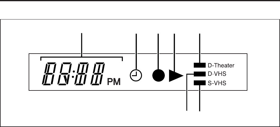
84 EN
Front display panel
1Channel and auxiliary input (“L-1”, “L-2”, “F-1”
and “I-1” etc.)
Clock time : pg. 28
2Timer mode indicator : pg. 35, 39
3Record mode indicator : pg. 26 – 28
4Play mode indicator : pg. 21, 22
INDEX (cont.)
5D-Theater indicator : pg. 25
6D-VHS indicator : pg. 26, 27
7S-VHS indicator : pg. 58, 59
6
234 51
7
MV8300_U1B-EN72-88 4/1/3, 2:28 PM84
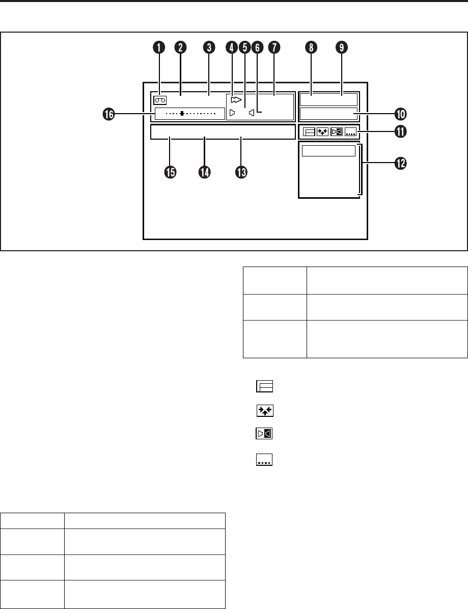
EN 85
On-screen display
1Cassette indication
2Cassette type indication : pg. 26
3Index no. indication : pg. 24
4VCR operation mode indication
5Audio monitor indications : pg. 23
6Clock time
Time counter*
Tape remaining time (When “REMAIN”
appears)**
* To reset the time counter, press C. RESET on the Remote.
The counter reading becomes “0:00:00”. It is also reset
when a tape is inserted.
** The tape remaining time is calculated based on the
recording speed being used. The indicated remaining
time is only an estimate.
7Recording mode indication : pg. 26, 27
Recording speed indication
8Image format (HD/SD)
9Channel and auxiliary input (“L-1”, “L-2”, “F-1”
and “I-1” etc.)
0 Audio Indications
STEREO When receiving the stereo broadcast
SAP When receiving SAP (Second Audio
Program) broadcast
SAP STEREO When receiving stereo and SAP
broadcast
Dolby D When playing back and receiving a
Dolby Digital signals
D-VHS
D-VHS MARANTZ MV8300
OFF
CC1
CC2
CC3
CC4
B E
D-VHS STD
12:59 AM
INDEX -9
CH 123HD
LR SAP
STREAM When playing back and receiving a
audio signals in other new formats
PCM When playing back and receiving a
PCM audio signals
AUDIO 1
AUDIO 2
1+2 MIX
Depends on the “DV AUDIO REC”
setting ( pg.55)
!Icons : pg. 25
: appears when a D-VHS cassette contains
the multiple programs
: appears when a D-VHS cassette contains
the multiple angle
: appears when a D-VHS cassette contains
the audio in multiple language
: appears when a D-VHS cassette contains
the subtitle in multiple language
NOTE:
The subtitles does not appear while the on-screen display is
displayed.
@Selections of the selected icon (!)
#Model name of the device connected to the
i.LINK connector
$Brand name of the device connected to the
i.LINK connector
%Type of device connected to the i.LINK
connector
^Tape position indicator : pg. 22
MV8300_U1B-EN72-88 4/1/3, 2:28 PM85
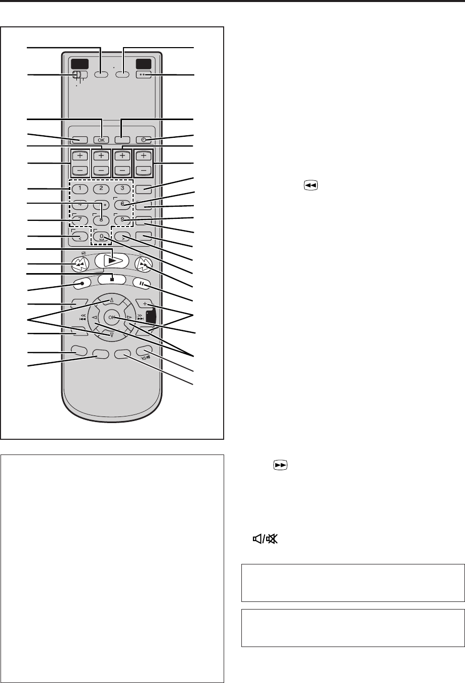
86 EN
Remote 1A/B/C/D button : pg. 71
2VCR/TV/CABLE/DBS selector : pg. 68 – 71
3OK Button
4PROGRAM button : pg. 34, 38
5STOP +/– button : pg. 35, 38
6START +/– button : pg. 35, 38
7Number keys : pg. 26, 27, 34
Character input buttons : pg. 49
8DAILY button : pg. 35, 39
9DBS button : pg. 39
0CANCEL button : pg. 34, 40
C. (Counter) RESET button : pg. 85
< button : pg. 49
!PLAY ( 3 ) button: pg. 21
@REW ( 1 ) button : pg. 21, 31
#STOP ( 7 ) button : pg. 21, 27
$REC ( ¶ ) button : pg. 26, 27
%MENU button: pg. 10
^%fi buttons: pg. 11
&NAVI button : pg. 42
*BACK button : pg. 35, 53
(OSD button : pg. 29
ENTER button : pg. 68 – 70
)TV/VCR button : pg. 68
qPOWER button : pg. 21, 27
wPROG. CHECK button : pg. 40
eTIMER ‰ button : pg. 35, 39, 40
rDATE +/– button : pg. 35, 38
tTV/VCR CH +/– buttons : pg. 26, 38, 68 – 70
yREC LINK button : pg. 62
u SUBTITLE button : pg. 25
iREC SPEED button : pg. 26, 27
oWEEKLY button : pg. 35, 39
pENTER button
QSKIP SEARCH button : pg. 24
W> button : pg. 49
EAUX button : pg. 67
RFF ( ¡ ) button : pg. 21, 31
TPAUSE ( 8 ) button : pg. 27, 32
YTV VOL +/– button : pg. 68
UOK Button
I4 ¢ (
@
#
) button : pg. 24
OA. (Audio) MONITOR button : pg. 23
(TV Muting) button : pg. 68
PDISPLAY button : pg. 28
How to use the Remote
Before use, insert two AA size batteries into the
Remote with the polarity (ª and ·) matched
correctly as indicated on the battery compartment or
on the lid.
The Remote can operate most of your VCR’s
functions, as well as basic functions of TV sets,
cable boxes and DBS receivers.
●Point the Remote toward the remote sensor on the
target component.
●The maximum operating distance of the remote
control is about 8 m.
NOTES:
●
If the Remote does not work properly, remove its batteries,
wait for a few seconds, replace the batteries and then try
again.
●
If the batteries of the Remote are discharged, the Remote
will not be able to control the TV, cable box or DBS
receiver. Replace the batteries.
START STOP DATE
PLAY
REW
REC
STOP
PAUSE
FF
TV/VCR CH
C. RESET
CANCEL
DBS DAILY
WEEKLY
ENTER
REC
LINK
REC
SPEED
SKIP
SEARCH
MENU
NAVI
SUBTITLE
VCR
PROGRAM PROG.CHECK TIMER
A/B/C/D
TV
TV/VCR
CABLE
/DBS
POWER
REMOTE
CODE
. , ? ABC DEF
GHI JKL MNO
PQRS TUV WXYZ
AUX
TV
VOL
A.
M
ON
I
TOR
D
ISPL
A
Y
OSD
EN
TER
BA
C
K
q
p
Q
W
R
Y
T
o
)
y
u
U
I
O
P
i
w
e
r
t
7
6
!
@
#
%
^
&
(
*
2
3
8
9
4
0
1
5
$
E
INDEX (cont.)
The glow-in-the-dark buttons shown in white on the
illustration on the left column are helpful when
using the Remote in darkened rooms.
Buttons with a small dot on the left side of the name
can also be used to operate your TV after setting the
VCR/TV/CABLE/DBS selector to “TV”. ( pg. 68).
MV8300_U1B-EN72-88 4/1/3, 2:28 PM86

EN 87
GENERAL
Power requirement : AC 120 V`, 60 Hz
Power consumption
Power on : 42 W
Power off : 18 W
Temperature
Operating : 5°C to 40°C (41°F to 104°F)
Storage : –20°C to 60°C (–4°F to140°F)
Operating position : Horizontal only
Dimensions (W x H x D) : 435 mm x 94 mm x 383 mm
(17-3/16" x 3-3/4" x 15-1/8")
Weight : 5.5 kg (12.2 lbs)
Maximum recording time
D-VHS (HS) : 210 min. with DF-420 video
cassette
D-VHS (STD) : 420 min. with DF-420 video
cassette
D-VHS (LS3) : 1260 min. with DF-420 video
cassette
D-VHS (LS5) : 2100 min. with DF-420 video
cassette
S-VHS/VHS (SP) : 210 min. with ST-210 video
cassette
S-VHS/VHS (EP) : 630 min. with ST-210 video
cassette
VIDEO/AUDIO (D-VHS)
Video format : MPEG2 standard
Audio format : Encode MPEG1 Layer2
Decode MPEG1 Layer2/
Dolby Digital
LINEAR PCM (HS/STD)
Track composition
Tape speed : 33.4 mm/sec (HS mode)
16.67 mm/sec (STD mode)
5.55 mm/sec (LS3 mode)
3.33 mm/sec (LS5 mode)
Head azimuth : ±30 deg
Drum rotation : 1800 rpm
Tracking system : CTL track system
Recording specification
Main data input rate : 28.2 Mbps (HS mode)
14.1 Mbps (STD mode)
4.7 Mbps (LS3 mode)
2.8 Mbps (LS5 mode)
Interface : IEEE1394 compliant
DTCP digital copy protection
compatible
VIDEO/AUDIO (S-VHS/VHS)
Format : S-VHS/VHS NTSC standard
Signal system : NTSC-type color signal and
EIA monochrome signal,
525 lines/60 fields
Recording/
Playback system : DA-4 (Double Azimuth) head
helical scan system
Signal-to-noise ratio : 45 dB
Frequency range
Normal audio : 70 Hz to 10,000 Hz
Hi-Fi audio : 20 Hz to 20,000 Hz
SPECIFICATIONS
TUNER
Tuning system : Frequency-synthesized tuner
Channel coverage
VHF : Channels 2–13
UHF : Channels 14–69
CATV : 113 Channels
TIMER
Clock reference : Quartz
Program capacity : 1-year programmable timer/
24 programs
Memory backup time : Approx. 10 min.
CONNECTORS
Input/Output : i.LINK IN/OUT (DV IN) x 2
(4-pin, S400)
RCA connectors
(IN x 3, OUT x 2)
S-video connectors
(IN x 3, OUT x 2)
Component video OUT
(Y, PB/CB, PR/CR) x 1
Digital OUT
(optical) x 1
ACCESSORIES
Provided accessories : Infrared remote control unit,
“AA” battery x 2,
Audio cable,
RF cable (F-type),
S-video cable (4-pin),
Controller
Specifications shown are for SP mode unless specified
otherwise.
E. & O.E. Design and specifications subject to change without
notice.
MV8300_U1B-EN72-88 4/1/3, 2:28 PM87

Printed in Japan
is a registered trademark.
www.marantz.com
You can find your nearest authorized distributor or dealer on our website.
JAPAN Marantz Japan, Inc. 35-1 Sagami Ohno 7-Chome, Sagamihara-shi, Kanagawa 228-8505, Japan
U.S.A. Marantz America, Inc. 1100 Maplewood Drive, Itasca, IL 60143, U.S.A.
EUROPE Marantz Europe B.V. P.O. Box 8744, 5605 LS Eindhoven, The Netherlands
2003/03 LPT0790-001A
MV8300_U1B-EN72-88 4/1/3, 2:28 PM88
