Marantz Pmd671 Users Manual PMD671_1 24_KG
PMD671_manual PMD671_manual T E X T F I L E S
PMD671 to the manual decf7c47-38b7-48b4-b343-fa5236b0faf3
2015-02-03
: Marantz Marantz-Pmd671-Users-Manual-466492 marantz-pmd671-users-manual-466492 marantz pdf
Open the PDF directly: View PDF ![]() .
.
Page Count: 63

Model PMD671 User Guide
®
Portable Solid State Recorder
CAUTION
RISK OF ELECTRIC SHOCK DO NOT OPEN
Warnings and Cautions
The lightning flash with arrowhead symbol within an equilateral triangle is intended to alert
the user to the presence of uninsulated “dangerous voltage” within the product’s enclosure
that may be of sufficient magnitude to constitute a risk of electric shock to persons.
The exclamation point within an equilateral triangle is intended to alert the user to the
presence of important operating and maintenance (servicing) instructions in the literature
accompanying the product.
- 2 -
WARNING
TO REDUCE THE RISK OF FIRE OR ELECTRIC SHOCK,
DO NOT EXPOSE THIS APPLIANCE TO RAIN OR MOISTURE.
CAITION: TO PREVENT ELECTRIC SHOCK, MATCH WIDE BLADE OF PLUG TO WIDE SLOT,
FULLY INSERT.
ATTENTION: POUR ÉVITER LES CHOC ÉLECTRONIQUES, INTRODUIRE LA LAME A PLUS
LARGE DE LA FICHE DANS LA BORNE, CORRESPONDANTE DE LA PRISE ET POUSSER
JUSQU'A FOND.
CAUTION: TO REDUCE THE RISK OF ELECTRIC SHOCK, DO NOT REMOVE COVER (OR BACK).
NO USER-SERVICEABLE PARTS INSIDE. REFER SERVICING TO QUALIFIED SERVICE PERSONNEL.
NOTE TO CATV SYSTEM INSTALLER:
This reminder is provided to call the CATV (Cable-TV) system installer's attention to Article 820-40 of the NEC,
which provides guidelines for proper grounding and, in particular, specifies that the cable ground shall be
connected to the grounding system of the building, as close to the point of cable entry as practical.
NOTE:
This equipment has been tested and found to comply
with the limits for a Class B digital device, pursuant to
Part 15 of the FCC Rules. These limits are designed to
provide reasonable protection against harmful inter-
ference in a residential installation. This equipment
generates, uses and can radiate radio frequency en-
ergy and, if not installed and used in accordance with
the instructions, may cause harmful interference to
radio communications. However, there is no guaran-
tee that interference will not occur in a particular
installation. If this equipment does cause harmful
interference to radio or television reception, which can
be determined by turning the equipment off and on,
the user is encouraged to try to correct the interfer-
ence by one or more of the following measures:
• Reorient or relocate the receiving antenna.
• Increase the separation between the equipment
and receiver.
• Connect the equipment into an outlet on a circuit
different from that to which the receiver is con-
nected.
• Consult the dealer or an experienced radio/TV tech-
nician for help.
NOTE:
Changes or modifications may cause this unit to fail to
comply with Part 15 of the FCC Rules and may void the
user’s authority to operate the equipment.
This Class B digital apparatus complies with Cana-
dian ICES-003.
Cet appareil numérique de la Classe B est conforme
á la norme NMB-003 du Canada.

- 3 -
Important Safety Instructions
READ BEFORE OPERATING EQUIPMENT
This product was designed and manufactured to meet strict quality
and safety standards. There are, however, some installation and op-
eration precautions which you should be particularly aware of.
1. Read these instructions.
2. Keep these instructions.
3. Heed all warnings.
4. Follow all instructions.
5. Do not use this apparatus near water.
6. Clean only with dry cloth.
7. Do not block any ventilation openings. Install in accordance with
the manufacture’s instructions.
8. Do not install near any heat sources such as radiators, heat reg-
isters, stoves, or other apparatus (including amplifiers) that pro-
duce heat.
9. Do not defeat the safety purpose of the polarized or grounding-
type plug. A polarized plug has two blades with one wider than
the other. A grounding type plug has two blades and a third
grounding prong. The wide blade or the third prong are provided
for your safety. If the provided plug does not fit into your outlet,
consult an electrician for replacement of the obsolete outlet.
10. Protect the power cord from being walked on or pinched particu-
larly at plugs, convenience receptacles, and the point where they
exit from the apparatus.
11. Only use attachments/accessories specified by the manufacturer.
12. Use only with the cart, stand, tripod,
bracket, or table specified by the manu-
facturer, or sold with the apparatus. When
a cart is used, use caution when moving
the cart/apparatus combination to avoid
injury from tip-over.
13. Unplug this apparatus during lightning
storms or when unused for long periods
of time.
14. Refer all servicing to qualified service personnel. Servicing is re-
quired when the apparatus has been damaged in any way, such
as power-supply cord or plug is damaged, liquid has been spilled
or objects have fallen into the apparatus, the apparatus has been
exposed to rain or moisture, does not operate normally, or has
been dropped.
Additional Safety Information!
• This product should not be placed in a built-in installation such as
a bookcase or rack unless proper ventilation is provided or the
manufacturer’s instructions have been adhered to.
• Apparatus shall not be exposed to dripping or splashing and that
no objects filled with liquids, such as vases, shall be placed on
the apparatus.
• When the switch is in the OFF position, the apparatus isn’t com-
pletely switched-off from the MAINS.
WARNINGS
• Do not expose the equipment to rain or mois-
ture.
• Do not remove the cover from the equipment.
• Do not insert anything into the equipment
through the ventilation holes.
• Do not handle the mains lead with wet hands.
• Do not cover the ventilation with any items such
as tablecloths, newspapers, curtains, etc.
• No naked flame sources, such as lighted
candles, should be placed on the equipment.
• When disposing of used batteries, please
comply with governmental regulations or
environmental public instruction's rules that
apply in your country or area.
• Do not place anything about 0.1 meter above
the top panel.
• Make a space of about 0.1 meter around the
unit.
• No objects filled with liquids, such as vases,
shall be placed on the apparatus.
• When the switch is in the OFF position, the
equipment is not completely switched off from
MAINS.
When setting up the recorder ensure that:
• it will not be exposed to interference from
external equipment.
• it will not be exposed to electrostatic dis-
charges.
• it will not be exposed to direct sunlight.
• heavy objects are not placed on the recorder.
Copyright
Recording and playback of any material may require
consent. For further information refer to the following
US ordinances:
• Copyright act of 1956
• Dramatic and Musical Performance Act 1958
• Performers Protection Acts 1963 and 1972
• any subsequent statutory enactments and orders
MARANTZ EUROPE B.V.
5600 EINDHOVEN
THE NETHERLANDS
SI DICHIARA CHE L’APPARECCHIO SINTO-AMPLIFACATORE SR-39 RISPONDE
ALLE PRESCRIZIONI DELL’ART. 2 COMMA 1 DEL D.M. 28 AGOSTO 1995 N° 548.
FATTO A EINDHOVEN, IL 1/1/1997.
CE marking (only EU version)
English
This product is in conformity with the EMC directive and low-voltage directive.
Français
Cet appareil est conforme á la directive EMC et á la de directive sur les basses
tensions.
Deutsch
Dieses Greät entspricht den EMC-Richtlinien und den Richtlinien für
Niederspannungsgeräte.
Nederlands
Dit apparaat voldoet aan de EMC-richtlijnene en de richtlijnen vooor apparatuur
met laag voltage.
Italiano
Quest' unitá è conforme alle diretive EMC ed alla direttiva sulle basse tensioni.
Português
Esta unidade está em conformidade com as directivas EMC e as directivas de
baixa voltagem.
Español
Esta unidad estáde acuerdo con las normas EMC y las relacionadas con baja
tensión.
Equipment mains working system
This product complies with household power and safety requirements in your area.
- 4 -
“Este aparato lleva elementos antiparasitarios necesarios para cumplir con ls limites
que se estableren en el Anexo V del Reglamento sobre Pertubaciones Radioelectricas e
Interferencias aprobado en el Real Decreto 138/1989. (B.O.E. de 9 Febrero 1989).”
- 5 -
Quick Start
Follow the instructions on this page to Quick Start your
new PMD671 Portable Solid State Recorder and begin
recording.
Note: Outside of the USA, a CF card is not included.
See page 49 for installing a CF card and page 21 to
format a CF card.
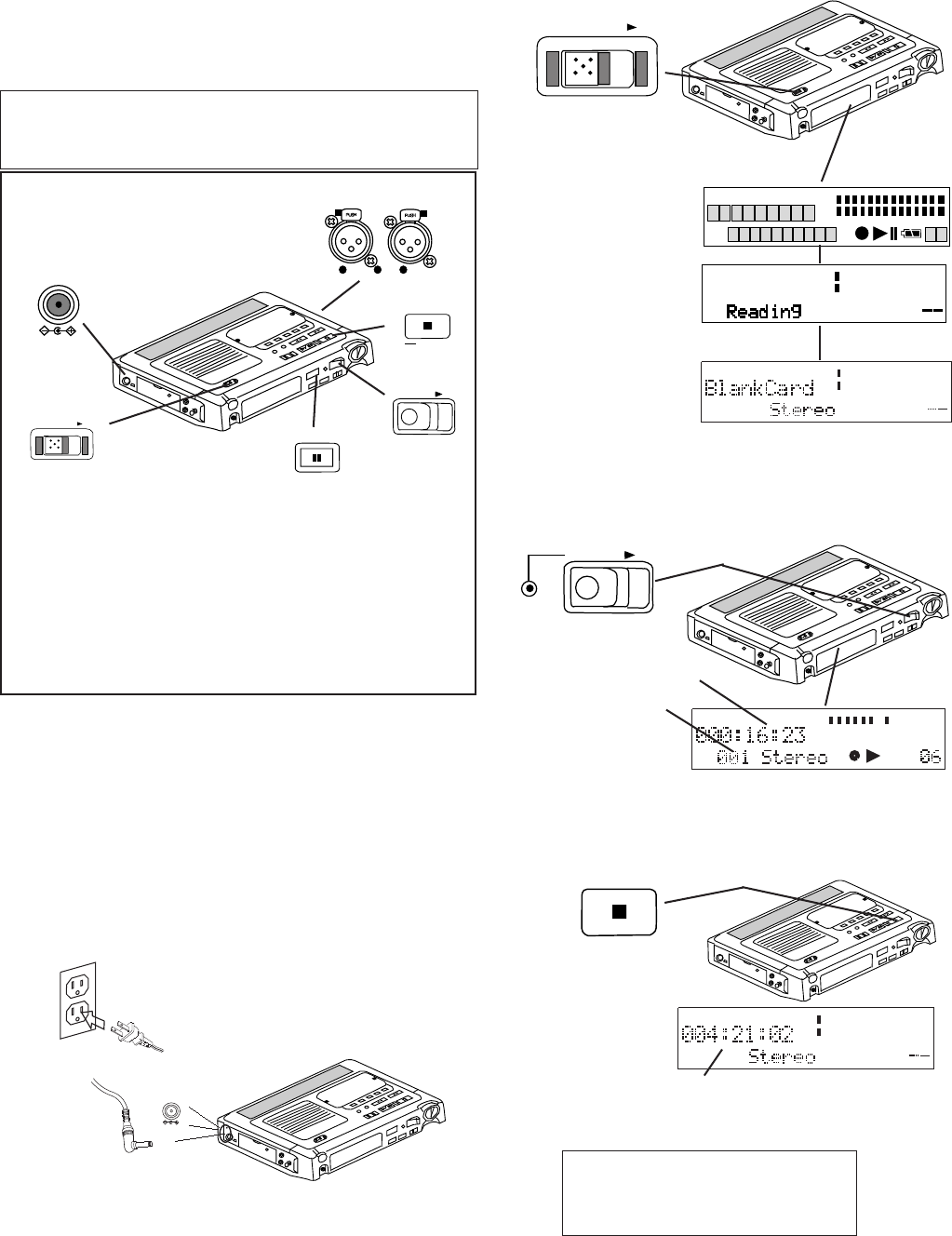
a. Plug the AC power pack
into household power.
b. Plug the power jack into the PMD671 at DC IN
15V.
2. Slide the POWER switch to the right and release.
On first power up, wait
for the PMD671 to
initialize.
A full display will
appear momentarily.
The display will change
to Loading then to
Reading.
The display will change
to BlankCard for a
newly formatted CF
card.
POWER
MARK
TRACK
TOTAL TRACK TIME
REC REMAIN kbps A-B L
R
-dB
PM
kHz
AM
INT
MIC
LINE
S.SKIP -dB
over
0
26
12
20
40
00
L
R
-dB
over
0
26
12
20
40
00
-dB
MIC
TRACK
TIMETRACK
-dB
00 40 20 12 6 2 0 over
-dB
R
L
The Rec indicator (a)
will be lit and steady
while recording. b
c
4. Push and release the STOP button to stop record-
ing and end the track (close the audio file).
REC
The display will
show the recording
time (b) of the
current track (c).
The display will
show the remaining
recording time at
current settings for
the CF
card.
a
MIC
-dB
00 40 20 12 6 2 0 over
-dB
R
L
REMAINREC TIME
STOP
a. Plug the AC adapter in.
b. Slide the POWER switch to turn on.
c. Connect your microphones.
d. Slide the REC switch to start recording.
e. Push and release REC PAUSE when record-
ing is not necessary.
f. Slide the REC switch to resume recording.
g. Push the STOP button to stop recording.
POWER
CANCEL
STOP
REC
REC PAUSE
DC IN 15V
a.
b. d. f.
e.
g.
Quick Start Basic Instructions
To transfer audio files to your computer:
transfer the CF card, see page 49,
or
connect via USB, see page 51.
MIC
-dB
00 40 20 12 6 2 0 over
-dB
R
L
Quick Start Detailed Instructions
The PMD671 comes with factory preset defaults for
MP3 recording using external microphones. These
settings are for recording a vocal or musical perfor-
mance. Quick Start ignores changing any of these
presets. Battery installation is not required.
1. Unpack the AC power pack, power cord and the
PMD671.
example shows 4 hours 21 minutes and 02 seconds
remaining
3. Connect your microphones (see p 53), then slide
the REC button to the right and release.
Recording begins.
3COLD
2HOT
2
31
2
31
1GND
LR
MIC
c.
DC IN 15V

- 6 -
Table of Contents
Precautions
Warnings and Cautions ........................... 2
Important Safety Instructions ................... 3
CE markings ............................................ 4
Quick Start ................................................... 5
Table of Contents ......................................... 6
US/Europe models ....................................... 7
Package Contents ........................................ 7
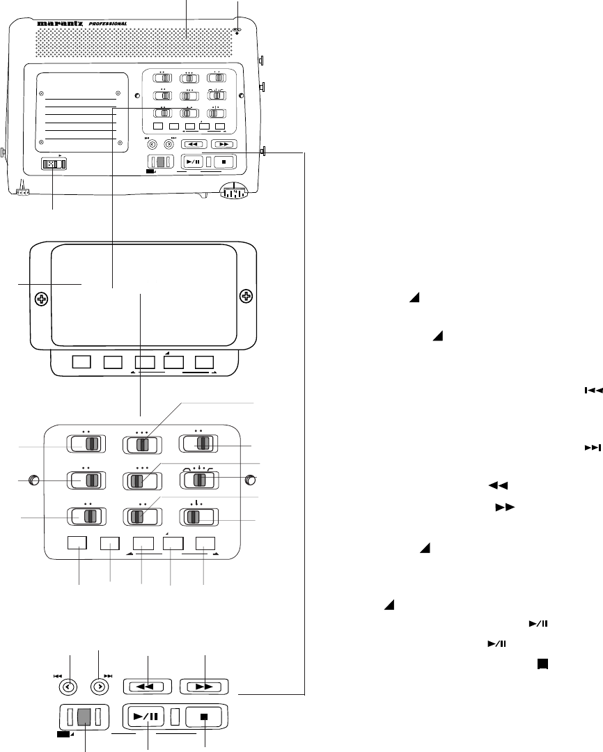
Control and Connection Diagrams
Top ........................................................... 8
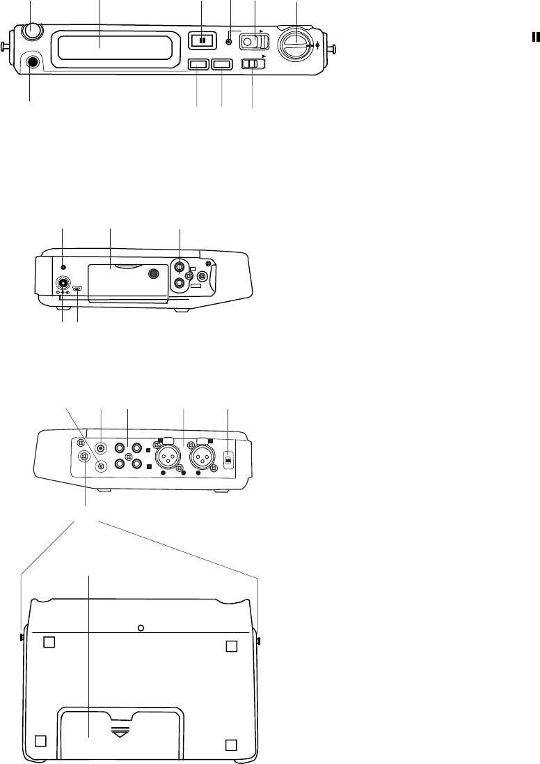
Front ........................................................ 9
Left side ................................................... 9
Right side ................................................. 9
Bottom ..................................................... 9
Display ..................................................... 10
Introduction .................................................. 10
Features ....................................................... 12
Controls and Connections
Top ............................................................ 13
Speaker .................................................. 13
MIC (internal microphone)...................... 13
POWER switch ....................................... 13
Security cover ........................................ 13
Recording setup controls
MONITOR switch ................................... 13
PRE REC switch .................................... 15
INPUT LOCK switch ............................... 15
AUDIO OUT switch ................................ 15
MIC ATTEN switch ................................. 15
REPEAT switch ...................................... 15
ANC switch............................................. 16
EDL PLAY switch.................................... 16
LEVEL CONT. switch ............................. 16
INPUT button.......................................... 17
What the Input selections do ............... 17
Inputs / channels recorded .................. 17
A-B REPEAT button ............................... 18
A-B Repeat playback......................... 18
MARK/ EDIT buttons ........................... 18
EDL Marks .......................................... 18
Adding EDL Marks ........................... 18
Locating EDL Marks ........................ 18
Custom playback sequences........... 19
Editing EDL Marks ........................... 19
EDL A-B looping .............................. 19
EDIT button ..................................... 20
Edit mode ........................................ 20
How to renumber tracks ................... 20
How to erase tracks.......................... 20
How to erase all EDL marks
within one track ................................ 21
How to erase all EDL marks ................ 21
How to format a CF card ..................... 21
How to check a CF card ...................... 22
TRACK JUMP buttons............................ 23
TRACK JUMP reverse button ....... 23
REC UNDO button .............................. 23
TRACK JUMP forward button ....... 23
-/F.REV button .................................... 23
F.FWD/+ button .................................. 23
MARGIN RESET/
USB MENU/STORE button ................... 24
MARGIN RESET button ............................ 24
USB button ................................................ 24
MENU/STORE button ........................... 24
MENU operations ....................................... 24
Select Preset ............................................. 24
Menu settings ............................................ 25
How to set or change the
Date / time ................................................. 26
Date Form ................................................. 27
Beep .......................................................... 28
A.PowOff ................................................... 28
Batt Type ................................................... 29
RecFormat ................................................ 30
Digi-IN Rec Format ................................... 34
RAW Mode ................................................ 34
Verify ......................................................... 35
PupPreRec ................................................ 35
St Mode ..................................................... 36
Mono Mode ............................................... 37
Auto Mark .................................................. 37
Manual TR................................................. 38
Auto TRK ................................................... 39
SeamlsPly ................................................. 40
SilentSkp ................................................... 40
Auto Cue ................................................... 41
S.Monitor ................................................... 42
SinglePly ................................................... 43
Remote Mode............................................ 44
Broadcast Wave ID numbers .................... 44
Default ....................................................... 45
PLAY/PAUSE /
ENTER button .................................... 46
PLAY/PAUSE button ........................ 46
ENTER button ................................. 46
STOP/CANCEL button ......................... 46
Front
HP/SP VOLUME control ........................... 47
Display ...................................................... 47
REC PAUSE button ............................... 47
REC indicator ............................................ 47
REC switch................................................ 47
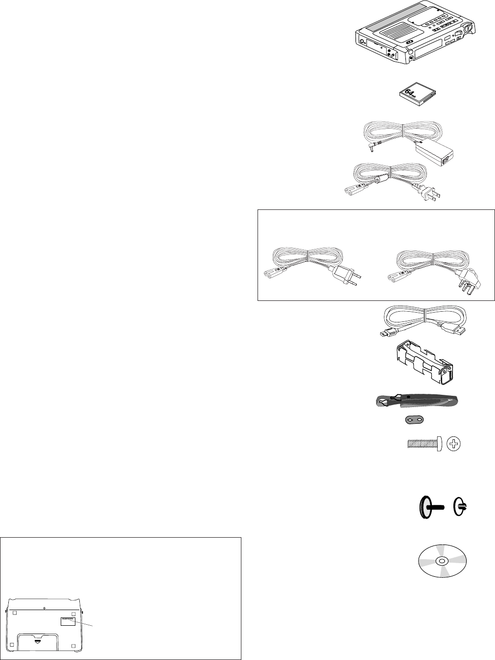
Package contents
• PMD671
• 64MB CF card (US only)
(shipped formatted and
installed)
• AC power pack
• power cord
Europe models include 2 power cords
CEE BS
• USB cable (3 ft)
• AA battery carrier
• Carry strap
• Carry strap retainers (2)
• Security screws (3)
ISO 3x10 (3mm x 10mm long)
For Memory compartment door (1)
or Security cover (2 spares)
• Plastic pin and retainer
(spare -
for Memory compartment door)
•CD
Contents of the CD may vary.
Contents usually include:
• PDF format manual(s)
Several languages may be included.
• Demonstration copy of PMDEdit software
• Instructions for obtaining full copy of PMDEdit
• This User Guide
• Customer Registration Document
- 7 -
REC LEVEL controls ................................. 47
PHONES jack............................................ 48
DISPLAY button ........................................ 48
LIGHT button............................................. 48
KEY LOCK switch ..................................... 49
Left side
CHARGE indicator .................................... 49
CF card compartment ............................... 49
To eject a CF card .................................. 49
To insert a CF card ................................. 49
Security .................................................. 50
DIGITAL IN/OUT jacks .............................. 50
DC IN 15V jack.......................................... 50
USB port.................................................... 50
How to connect via USB port .............. 51
Right side
REMOTE1 jack ......................................... 52
Remote Mode ........................................ 52
REMOTE2 jack ......................................... 52
LINE OUT/IN jacks .................................... 52
MIC IN jacks .............................................. 53
PHANTOM +48V switch ............................ 53
Microphone recommendations ........... 53
Carry studs ................................................ 53
Installing the carry strap ..................... 53
Bottom
Battery compartment ................................. 53
Battery power ....................................... 54
Installing AA size batteries ............... 54
Installing/Changing an optional
Ni-Cd or Ni-MH battery ...................... 54
Display ........................................................ 55
Care and maintenance ................................. 56
Recording time chart .................................... 57
Rec Format charts........................................ 58
Menu defaults............................................... 59
Troubleshooting ........................................... 60
Error Messages ............................................ 60
Specifications ............................................... 61
Optional accessories .................................... 61
Record setting recommendations ................ 61
Warranty ....................................................... 62
MODEL NO. PMD670/U1B
MODEL NO. PMD671/UIB
or
MODEL NO. PMD671/N1B
US/Europe models
The US model PMD671/UIB distributed in the USA, and
European model PMD671/N1B distributed elsewhere,
differ slightly in supplied accessories and default
settings. Those differences are noted in this User Guide.
- 8 -
SOLID STATE RECORDER PMD671
POWER
MIC ATTEN
0dB -20dB
FLAT
ANC
LEVEL CONT.
LIMITER
ALC MANUAL
OFF ON
EDL PLAY
STEREO
L
AUDIO OUT
R
SOURCE FILE
MONITOR
OFF ON
PRE REC
MARK
A-B REPEAT
INPUT
EDIT
SINGLE
OFF ALL
OFF ON
INPUT LOCK
TRACK JUMP
MARGIN RESET
REC
UNDO
MENU/STORE ENTER CANCEL
PLAY / PAUSE STOP
USB
-
/
REW FWD
/
+
ALLOFFSINGLE
R
AUDIO OUT
L
STEREO
FLAT
-20dB0dB
MIC ATTEN
REPEAT
EDL PLAY
ON
OFF MANUALALC
LIMITER
LEVEL CONT.
ANC
INPUT LOCK
ONOFF
PRE REC
ONOFF
MONITOR
FILESOURCE
EDIT
INPUT A-B REPEAT MARK
TRACK JUMP
MARGIN RESET
REC
UNDO
MENU/STORE ENTER CANCEL
PLAY / PAUSE STOP
USB
-
/
F.REV F.FWD
/
+
1 2
3
5
6
7
8
9
10
11
12
13
14 15 16 17 18
19 20 21 22
23 24 25
INPUT A-B REPEAT MARK
EDIT
4
Control and Connection Diagrams
# Control Page
Top
1Speaker ..................................................... 13
2MIC (internal microphone)......................... 13
3POWER switch .......................................... 13
4Security cover ........................................... 13
Setup controls
5MONITOR switch ...................................... 13
6PRE REC switch ....................................... 15
7INPUT LOCK switch .................................. 15
8AUDIO OUT switch ................................... 15
9MIC ATTEN switch .................................... 15
10 REPEAT switch ......................................... 15
11 ANC switch ................................................ 16
12 EDL PLAY switch....................................... 16
13 LEVEL CONT. ........................................... 16
14 INPUT button............................................. 17
15 A-B REPEAT button .................................. 18
MARK/ EDIT controls
16 Mark reverse button .................................. 18
17 MARK/ EDIT button ................................ 18
18 Mark forward button .................................. 18
Record/Playback controls
19 TRACK JUMP reverse button
(playback) .................................................. 23
REC UNDO button (record) ...................... 23
20 TRACK JUMP forward button
(playback) .................................................. 23
21 -/F.REV button .................................... 23
22 F.FWD/+ button .................................. 23
23 MARGIN RESET/
USB MENU/STORE button
MARGIN RESET button (playback) .......... 24
USB button ................................................ 24
MENU/STORE button ........................... 24
24 PLAY/PAUSE button (playback) ......... 46
ENTER button (menu) ........................ 46
25 STOP/CANCEL button .......................... 46
PUSH
PUSH
MIC
GND HOT COLD OFF
ON
+48V
PHANTOM
REMOTE 1
REMOTE 2
IN
LINE
1
3
21
3
2
R
R
R
R
L
L
L
L
1
1
2
2
3
3
- 9 -
REC PAUSE
DISPLAY LIGHT
REC
LEVEL
L
R
REC
HP/SPK VOLUME
PHONES
KEY LOCK
1 2 3 4 5 6
7 8 9 10
DIGITAL
IN
OUT
CHARGE
DC IN 15V
USB
11 12 13
14 15
16 17 18 19 20
22
21
# Control Page
Front
1HP/SPK VOLUME control ...................... 47
2Display (see next page) ......................... 47
3REC PAUSE button ............................ 47
4REC indicator. ........................................ 47
5REC switch............................................. 47
6REC LEVEL controls .............................. 47
7PHONES jack ......................................... 48
8DISPLAY button ..................................... 48
9LIGHT button .......................................... 48
10 KEY LOCK switch .................................. 49
Left side
11 CHARGE indicator ................................. 49
12 CF card compartment ............................ 49
13 DIGITAL IN/OUT jacks ........................... 50
14 DC IN 15V jack....................................... 50
15 USB port................................................. 50
Right side
16 REMOTE 1 jack ..................................... 52
17 REMOTE 2 jack ..................................... 52
18 LINE IN/OUT jacks ................................. 52
19 MIC IN jacks ........................................... 53
20 PHANTOM power switch........................ 53
21 Carry studs ............................................. 53
Bottom
22 Battery compartment .............................. 53
- 10 -
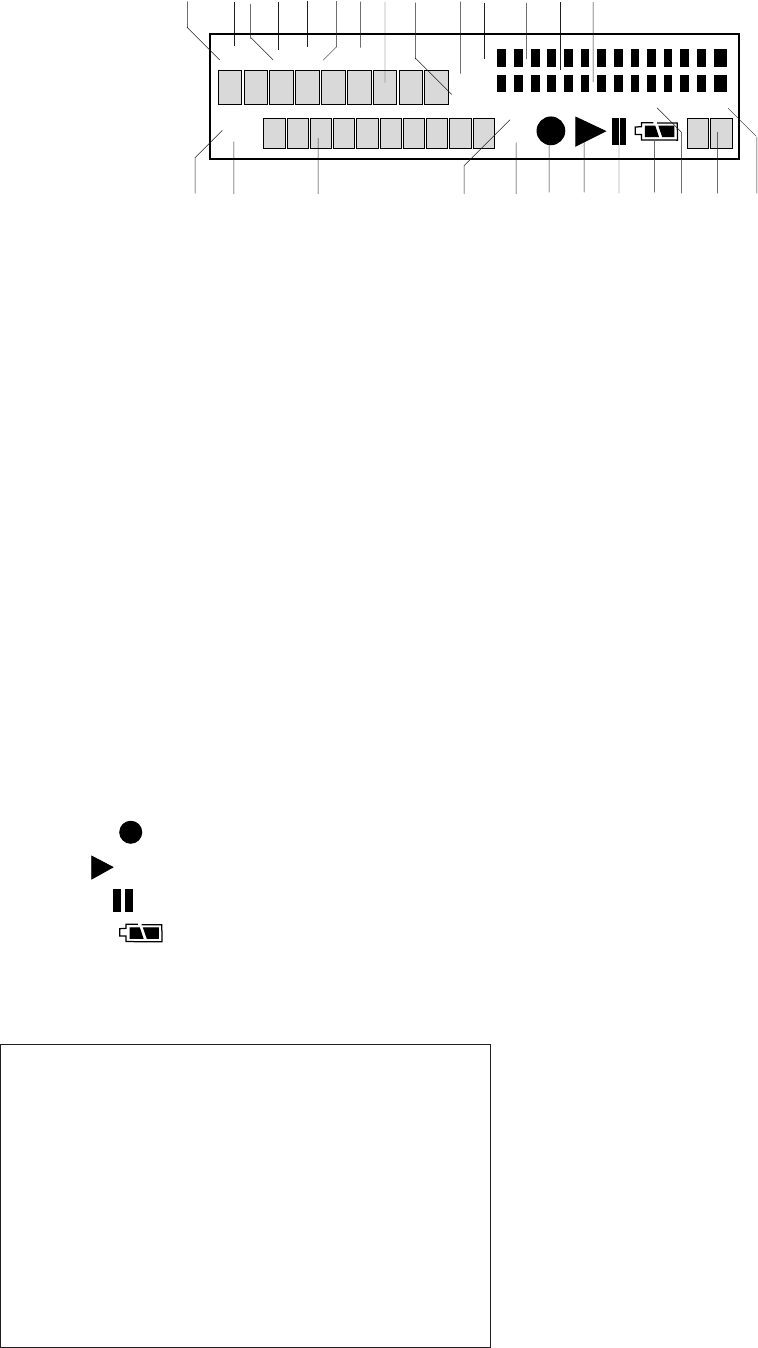
# Control Page
Display
1REC label ............................................... 55
2TOTAL label............................................ 55
3REMAIN label ........................................ 55
4TRACK label .......................................... 55
5TIME label .............................................. 55
6kbps label ............................................... 55
7A-B label................................................. 55
8Upper alphanumeric display................... 55
9AM/PM label ........................................... 55
10 kHz label ................................................ 55
11 L -dB R level meter labels ..................... 55
12 Left level meter....................................... 55
13 -dB over scale ....................................... 55
14 Right level meter .................................... 55
15 TRACK label ......................................... 55
16 MARK label ............................................ 55
17 Lower alphanumeric display................... 55
18 INT MIC label ......................................... 56
19 LINE label ............................................... 56
20 Record .............................................. 56
21 Play ................................................... 56
22 Pause ............................................... 56
23 Battery .......................................... 56
24 S. SKIP label .......................................... 56
25 Margin level ............................................ 56
26 -dB label ................................................. 56
1 2 3 4 5 6 7 8 9 10 11 12 13 14
MARK
TRACK
TOTAL TRACKTIME
REC REMAIN kbps A-B L
R
-dB
PM
kHz
AM
INT
MIC
LINE
S.SKIP -dB
over
0
26
12
20
40
00
15 16 17 18 19 20 21 22 23 24 25 26
Hint:
When making major changes to your recording setup,
we suggest the following procedure:
1. Identify the appropriate input device (internal
microphone, microphone(s), Line input, Digital
input).
2. Select the input menu choice corresponding to
your input device selection. (See page 17.)
3. If necessary, set or change the Rec Format
parameters for your recording situation. (See
page 30.)
Introduction
Thank you for selecting the Marantz Professional
PMD671 Portable Solid State Recorder. The
PMD671 is an audio recorder that records in
digital audio formats onto a Compact Flash™
memory card (CF card) or Microdrive™.
Compact flash memory cards, also used in digital
cameras, are widely available at consumer elec-
tronics retailers and computer resellers.
Audio inputs may be from:
• the built-in microphone,
• condenser or dynamic microphone(s) con-
nected to the XLR jacks,
• line level audio sources connected to the LINE
IN jacks, or
• digital audio sources in SP/DIF format con-
nected to the DIGITAL IN jack.
Audio outputs may be from:
• the built-in speaker,
• headphones connected to the PHONES jack,
• analog audio devices such as an amplifier or
other device connected to the LINE OUT
jacks, and/or
• digital audio devices using SP/DIF format
connected to the DIGITAL OUT jack.
Computer compatible
The PMD671 records directly onto CF cards.
Recordings can be transferred to your desktop or
laptop computer by removing the CF card from
the PMD671. You may also use the supplied cable
to connect the PMD671 to your computer via the
USB port. Audio recorded in the popular MP3
compression format is directly available for intra-
net or internet file sharing.
You can:
• log and archive audio files
- 11 -
• play audio files on your computer
• save audio files to:
• your hard drive
• a floppy
• a CD-R disc
• post streaming audio files on your web site
• use software and your computer to transcribe
digital recordings
An editing program (PMDEdit, available from
Marantz Professional for PC users) lets you
convert and edit audio files that were recorded
on the PMD671.
Presets
The PMD671 has three selectable Presets for
commonly used recording situations.
Preset 1, MP3 Stereo using your microphones,
for recording with relatively small files.
Preset 2, MP3 Mono using the internal micro-
phone, for recording meetings or voice with very
small files.
Preset 3, PCM Stereo using your microphones,
for very high quality audio recording.
• Security – recording
The PMD671 has several security features, not
previously available on Marantz Professional
digital recorders, that confirm recording is
accurately written to the CF card.
•Verify
Verify is electronic file verification. When
turned on in the Preset menu, Verify runs a
check between the audio at the source and
information written to the CF card.
•RAW
RAW (Read After Write / VTH - Virtual Third
Head) digitally mimics the third head of a
three head tape deck. While recording, audio
at the PMD671's outputs is audio that has
already been written to the CF card. With
about a 2 second delay, you can listen to the
audio written to the CF card, monitoring that
recording is actually taking place.
•Time Shift Playback
Time Shift Playback allows you to listen to
audio from anywhere on the CF card while
simultaneously recording the current source.
Note:
These recording security features are not available when
making 24 bit recordings. Simultaneous availability depends
on recording conditions. See page 14.
• Security – CF cards
For added security, the CF card compartment
door can be secured with a screw. This is
especially recommended if you transfer audio
files via the USB cable.
• Security – Input settings
After you have set up the input settings* for
your application, the settings can be set to ON
with the INPUT LOCK switch.
As an added precaution, the input setting
switches (including the ability to change input
devices) can be protected with the supplied
screw-on cover preventing unintentional
changes.
*Settings for recording meetings for example, will usually be
the same from meeting to meeting.
Voice recording
The PMD671 has several helpful features for
voice recording in situations such as meetings,
conferences or other events.
• Use less memory (longer recording time)
For voice recording, the recording quality level
(bit rate recorded and/or sampling frequency)
can be set to the lowest levels. This permits
more time recorded on the CF card.
• Easy recording
One control begins recording. Simply slide and
release the red REC switch.
Playback aids
A common problem with lengthy voice or other
recordings is difficulty in locating one or more
specific passages for playback. The PMD671
has several ways to mark or tag specific record
starting points.
• Date and time
A built-in date and time generator marks the
beginning of each track.
• Tracks
An audio recording is called a "track" when on
the PMD671 and an audio "file" when on your
computer.
- 12 -
Tracks are numbered from 01 to a maximum of
999.
A new track (file) is automatically started each
time recording is stopped using the STOP
button.
Using the "Auto TRK" feature, PMD671 can be
set to start a new track at specific time intervals
during recording (for example every minute).
Using the "Manual TR" feature, you can start a
new track during recording by sliding and re-
leasing the REC switch.
• Automatic recording
The PMD671 can be set to stop recording when
there is silence (SilentSkp feature) and auto-
matically start when sound resumes. The
PMD671 can be set to automatically add an
EDL mark (Auto Mark feature) to the track at
each such starting point.
• EDL marks*
EDL (Edit Decision List) marks can be created
during recording manually or automatically. EDL
marks help you find those specific points in the
recording.
*The EDL marking system is proprietary to Marantz Profes-
sional solid state recorders.
• During playback, you can search for EDL
marks in forward or reverse.
• You can change an EDL mark into a skip mark
or an A-B repeating point. That option allows
you to create custom playback sequences
which include skipping or repeating audio
between EDL marks.
• Up to 255 EDL marks can be added to a CF
card. EDL marks are numbered consecutively
starting at one. During recording, you can
manually add an EDL mark by pressing
MARK. EDL marks can be added automati-
cally, for example, at the beginning of each
track.
• PMDEdit computer software is specifically
designed for the PMD671. PMDEdit recog-
nizes EDL marks generated by the PMD671.
This is especially useful for editing audio files
on your PC. Visit www.d-mpro.com for more
information.
Features
• Stereo (2 channels) and mono (1 channel)
audio recording and playback.
• Records onto various types of CF cards.
(Please refer to the Marantz Professional
web site at www.d-mpro.com for a list of
recommended cards.)
• Two different recording formats:
• Compressed recording using MPEG1 Layer
II (MP2) or MPEG1 Layer III (MP3) mono
and stereo.
• Uncompressed recording using 16-bit or 24-
bit linear Pulse Code Modulation (PCM).
16-bit 44.1kHz PCM recordings are standard
CD quality.
24-bit 96kHz PCM recordings are high
quality recordings used in professional audio
and film studios.
• MS-DOS™ and Windows compatible file
system.
• Selectable file types:
• Wave (.wav)
• Broadcast Wave Format (.bwf or .wav)
• MP2 (.mpg)/MP3 (.mp3).
• Recording bit rate is selectable:
• .mpg/mp3 compressed at 32kbps (recom-
mended for dictation),
32, 48 or 64kbps (recommended for voice
recording), or
128 or 192 kbps (recommended for recording
music)
• PCM (.wav) uncompressed (very high quality
mono audio recording)
• PCM (.wav) uncompressed 24 bit/96kHz
(stereo) (recommended for very high quality
audio recording)
• Manual, manual with limiter and automatic
record level control (ALC).
• An ANC (Ambient Noise Cancel) switch for
reducing unwanted background noise.
• Electronic 'Read After Write' monitoring (time
shift) feature.
• Automatic electronic file verification feature
(Verify).
• CF card compatibility check feature (Card
Check).
• Pre-Recording memory buffer that records 2 to
4 seconds* of audio before recording is
started.
*Normally 4 seconds. Depends on Rec Format settings.
• Portions of multiple recordings can be played
back in sequence using EDL marks.
- 13 -
SOLID STATE RECORDER PMD671
POWER
MIC ATTEN
0dB -20dB
FLAT
ANC
LEVEL CONT.
LIMITER
ALC MANUAL
OFF ON
EDL PLAY
STEREO
L
AUDIO OUT
R
SOURCE FILE
MONITOR
OFF ON
PRE REC
MARK
A-B REPEAT
INPUT
EDIT
SINGLE
OFF ALL
OFF ON
INPUT LOCK
TRACK JUMP
MARGIN RESET
REC
UNDO
MENU/STORE ENTER CANCEL
PLAY / PAUSE STOP
USB
-
/
REW FWD
/
+
1 2
POWER
-dB
00 40 20 12 62 0 over
-dB
R
L
L
R
-dB over
0
26
12
20
40
00
-dB
• There are four ways to power the PMD671:
• Included AC adapter
• AA Alkaline batteries (~ 5 hours @ 1450 mAh
usage)
• Optional rechargeable Ni-Cd battery pack
RB1100 (~ 4 hours @1100 mAh usage).
• Optional rechargeable Ni-MH battery
RB1651 (~ 6 hours @1650 mAh usage).
• Built-in Time and Date generator marks the
beginning of each track.
• REMOTE1 jack permits a wired remote button
for controlling the recording process.
• REMOTE2 jack permits using the optional
RC600 remote for microphone interviews.
Controls and Connections
Top
1. Speaker
The played back audio signal is simulta-
neously output to the built-in speaker, the
PHONES jack, LINE OUT jacks and DIGITAL
OUT jack. Headphones plugged into the
PHONES jack mute the internal speaker. The
HP/SPK VOLUME control controls the built-
in Speaker and Headphone volume.
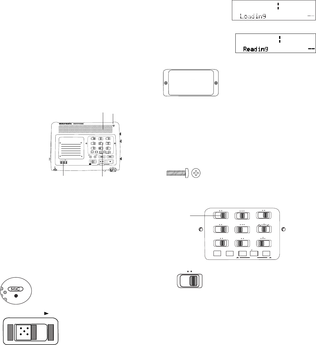
2. MIC (internal microphone)
3. POWER switch
Slide to the right and release
to turn Power on or off.
If the AC power pack is
connected at DC IN and plugged in, it powers the
PMD671.
If power is not detected at DC IN, battery power is
automatically used if available.
Loading is displayed,
then the screen goes
blank momentarily.
Reading is displayed
while the CF card is
read.
ALLOFFSINGLE
R
AUDIO OUT
L
STEREO
FLAT
-20dB0dB
MIC ATTEN
REPEAT
EDL PLAY
ON
OFF MANUALALC
LIMITER
LEVEL CONT.
ANC
INPUT LOCK
ONOFF
PRE REC
ONOFF
MONITOR
FILESOURCE
EDIT
INPUT A-B REPEAT MARK
5
MONITOR
FILESOURCE
When first powered up, the PMD671 takes some
time to initialize.
3 4
Security cover
Use a small Phillips screw-
driver to remove or replace
the Security cover.
The Security cover makes
setup controls relatively unavailable. The setup
controls allow you to setup the PMD671 for your
unique application. You can then have someone
operate the PMD671 without concern that they
might change something that could cause failure
to record.
Note: Two 3mm machine screws
10mm long are used for the
security cover.
Recording setup controls
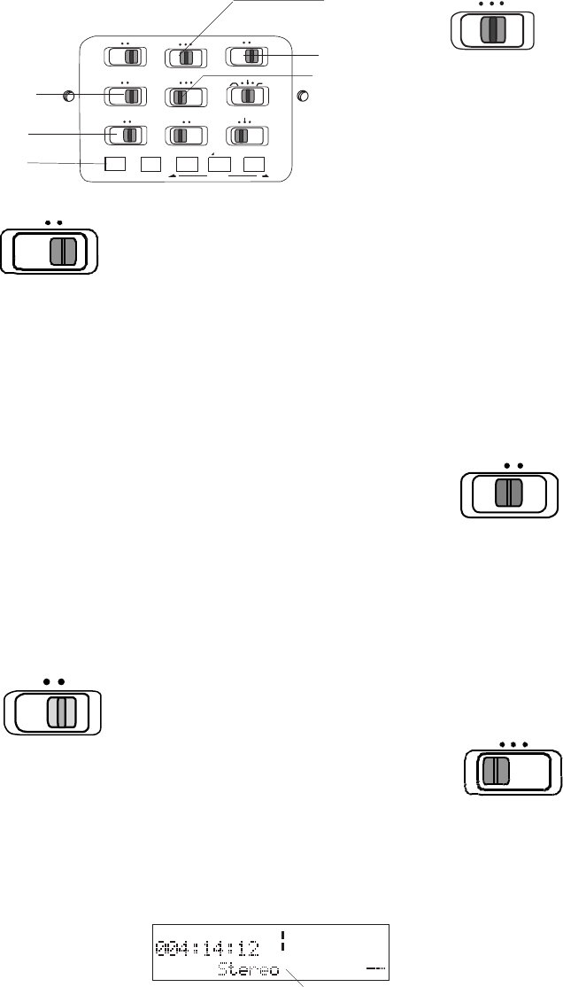
5. MONITOR switch
This switch turns the Read
After Write or Time Shift
Playback* feature on or off.
*Depending on the setting of RAW mode in the Menu.
When RAW Mode is at MONITOR, and the
MONITOR switch is at FILE when recording
begins, Read After Write is on.
When RAW Mode is at TimeShft, and the MONI-
TOR switch is at FILE when recording begins,
the Time Shift feature is on.
continues

- 14 -
RAW (VTH - Virtual Third Head)
RAW (Read After Write / VTH - Virtual Third
Head) digitally mimics the third head of a three
head tape deck. When on and the PMD671 is
recording, the audio that is output to the LINE
OUT, DIGI OUT, PHONES and SPEAKER is
audio that has already been written to the CF card
and not audio from the source. This allows you to
actually listen to audio written to the CF card,
monitoring that the recording is actually taking
place. When RAW is off, the audio to the LINE
OUT, DIGI OUT, PHONES and SPEAKER is
actually the source you are recording.
Time Shift (Time Shift Playback)
Time Shift Playback works just like RAW, in that it
monitors audio that has already been recorded to
the CF card. However, Time Shift allows you the
ability to listen to audio from anywhere on the
card while simultaneously recording the current
audio source.
FILE: During recording, output to the PHONES
and LINE OUT jacks is read from the CF card.
SOURCE: During recording, output to the
PHONES and LINE OUT jacks is the audio
source being recorded.
Factory defaults: MONITOR switch: SOURCE,
Presets 1, 2, and 3: RAW at MONITOR.
Notes:
• Active level meters verify that an audio source is being
received by the PMD671.
• Another way to verify that audio is being recorded is to
turn on the VERIFY menu choice (see page 35). When
VERIFY is ON, the PMD671 constantly compares the
recorded information to the source input. It verifies that
the file written to the card is exactly what was input.
• MONITOR is not available in 24 bit recording, or
available for MP2.
• MONITOR is available for 16 bit PCM recording and
MP3.
• An audio drop out may occur when using RAW at high
bit rates in MP3.
Time Shift lets you select the Read After Write
time delay. Time Shift playback allows you to play
audio that has already been recorded from any-
where on the CF card while simultaneously
recording the current audio. This is useful in
applications such as court recording.
When the Time Shift feature is on and the MONI-
TOR switch is set to file, as you begin recording
the outputs (for example headphones) monitor
the source. While recording is in progress, you
can press and release the -/F.REV button to
search back through and play the file that is being
recorded (to the point you began the Time Shift).
Audio played back through the headphones can
be anywhere on the CF card. You can use the
TRACK JUMP reverse or TRACK JUMP
forward buttons to change tracks.
Press and release the PLAY/PAUSE button
to return to monitoring the current recording.
Notes:
• In some instances, Verify and RAW or Time Shift are
available simultaneously (see charts below).
• When using RAW (Read After Write) to monitor informa-
tion already written to the CF card, the audio played
back will be about 2 seconds behind current events.
• RAW and Time Shift are only available individually.
Never at the same time.
•Not available when making 24-bit recordings. RAW
and Time Shift are not available when making 24-bit
recordings.
The chart below details which features are avail-
able during which RecFormats.
Additionally, Verify is available for use at the same
time as RAW (Read After Write) or Time Shift
(Time Shift Playback) in the following circum-
stances:
n/a
n/a
Verify
MP2 MP3PCM 24-bitPCM 16-bit
RAW, Time Shift n/a
Time Shift
MP3 with RAW /
RAW / Time Shift
PCM 16-bit with
Verify
PCM 24-bit
ALLOFFSINGLE
R
AUDIO OUT
L
STEREO
FLAT
-20dB0dB
MIC ATTEN
REPEAT
EDL PLAY
ON
OFF MANUALALC
LIMITER
LEVEL CONT.
ANC
INPUT LOCK
ONOFF
PRE REC
ONOFF
MONITOR
FILESOURCE
EDIT
INPUT A-B REPEAT MARK
7
OFF ON
INPUT LOCK
a
8
9
10
When power is on and the PMD671 is in REC/
PAUSE the recorder is constantly saving about 4
seconds* of audio input. This is called pre record
cache. When recording is resumed from REC
PAUSE by sliding the REC switch, the pre-
recorded seconds are recorded.
OFF: Turns the pre-record cache off.
ON: Leaves the pre-record cache on.
*Cache time varies with recording conditions:
• 24-bit PCM – 1 second
• 16-bit PCM, MP2, MP3 – 4 seconds
• 16-bit PCM, MP3 with RAW – 2 seconds.
Factory default: PRE REC switch at ON.
OFF ON
PRE REC
6
- 15 -
MIC ATTEN
0dB -20dB
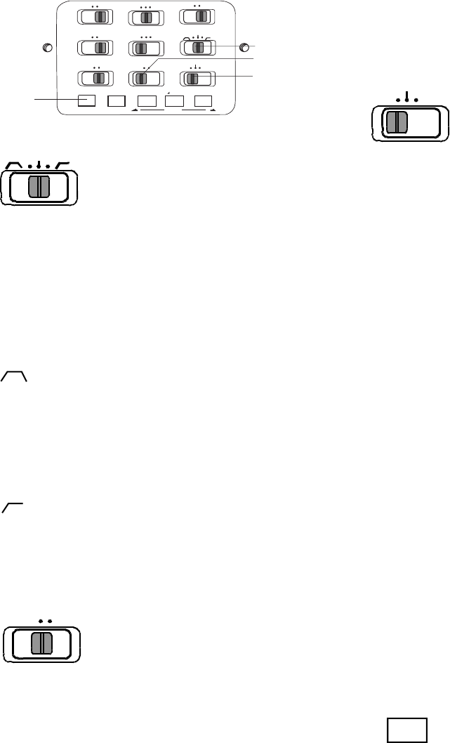
7. INPUT LOCK switch
The INPUT LOCK switch
lets you lock your selected
input settings with a switch
covered by the Security
cover.
OFF: When the INPUT LOCK switch is at OFF,
push and release the INPUT button (a) to tab
through the input choices. The selection “times
out” to the displayed input choice in 3 seconds.
Example
display MIC
ON: When the INPUT LOCK switch is at ON,
pushing the INPUT button (a) does nothing
(skips the input selection choices).
Factory default: INPUT LOCK switch at OFF.
8. AUDIO OUT switch
This switch selects the audio
output channel for playback.
Applies to playback output to LINE OUT, DIGITAL
OUT, and Internal speaker or headphones.
L: Audio recorded on the Left channel is output to
both the left and right output channels.
STEREO: Audio recorded on the Left channel is
output to the left output channel, and audio
recorded on the Right channel is output to the
right output channel. Both channels are output to
the internal speaker.
R: Audio recorded on the Right stereo channel is
output to both the left and right output channels.
Factory default: ANALOG OUT switch at STE-
REO.
9. MIC ATTEN switch
The microphone attenuation
switch permits the direct use
of microphones that differ in
sensitivity.
0dB: No microphone attenuation.
-20dB: Input from a microphone(s) connected to
the XLR MIC IN jacks is cut by -20dB.
Factory default: MIC ATTEN switch at 0dB.
R
AUDIO OUT
L
STEREO
MIC
-dB
00 40 20 12 6 2 0 over
-dB
R
L
REMAINREC TIME
6. PRE REC switch
This switch lets you turn
off pre record cache if it
is not desired.
SINGLE
OFF ALL
REPEAT
10. REPEAT switch
Lets you endlessly repeat
playback of a track or entire
memory card.
OFF: No repeat.
SINGLE: During playback, the current track is
repeated. When playback reaches the end of the
track, it automatically starts playback from the
beginning of that track.
ALL: During playback, all tracks are repeated.
When playback reaches the end of the last track,
it automatically starts playback from the beginning
of the first track.
Factory default: REPEAT switch at OFF.
Note:
For other methods of repeat playback, see the A-B REPEAT
button and/or EDL A-B looping (pages 18 and 19).
ALLOFFSINGLE
R
AUDIO OUT
L
STEREO
FLAT
-20dB0dB
MIC ATTEN
REPEAT
EDL PLAY
ON
OFF MANUALALC
LIMITER
LEVEL CONT.
ANC
INPUT LOCK
ONOFF
PRE REC
ONOFF
MONITOR
FILESOURCE
EDIT
INPUT A-B REPEAT MARK
11
12
13
- 16 -
ANC
FLAT
:
:
OFF ON
EDL PLAY
LEVEL CONT.
LIMITER
ALC MANUAL
11. ANC switch
The ANC (Ambient Noise
Cancel) switch lets you
reduce ambient noise
before recording on the internal microphone or
MIC inputs.
Ambient Noise Cancel positions do not change
the memory used in recording. Examples of low
ambient noise sources include: traffic, air condi-
tioning hum and wind noise.
Band pass position reduces the lows
and highs and passes (records) the center (voice
level) audio frequencies. This reduces the re-
cording of high and low frequency ambient noise.
FLAT: No filtering applied.
High pass position reduces low fre-
quency ambient noise only.
12. EDL PLAY switch
The EDL PLAY switch
turns EDL PLAY off or on.
OFF: When the EDL PLAY switch is at OFF,
PMD671 playback does not respond to EDL
mark instructions.
ON: When EDL PLAY is ON, PMD671 playback
follows EDL mark instructions regarding play-
back order, skipping sections of recording on the
memory card, or repeating a section of recording
on the memory card.
Note:
If the EDL PLAY switch is at ON and there are no EDL
marks on the CF card (recording was done with the AUTO
13. LEVEL CONT. switch
The LEVEL CONT(rol)
switch lets you select the
type of input level control.
MANUAL: At MANUAL, you control the input
level with the REC LEVEL controls.
LIMITER: At LIMITER, peak sound levels that
would distort the recording are limited.
ALC: At ALC (Automatic Level Control = Auto-
matic Gain Control), the PMD671 automatically
responds to changes in input level. If recording is
quiet, the input level is increased. If recording is
loud, the input level is decreased. This is a desir-
able feature when recording a meeting with
several speakers. A speaker close to the micro-
phone and/or with a loud voice will be automati-
cally recorded at a reduced level and a quiet
speaker will be recorded at an increased level.
Both will be less likely to have their input missed.
ALC is usually undesirable when recording music
(voice or instrument) because the transitions in
input level may be audible in the recording. ALC
can also make the recording ‘hissy’ by raising the
level during quiet passages and recording ambi-
ent noise.
The REC LEVEL controls do not work when the
LEVEL CONT. switch is set at ALC.
MARK switch at OFF, or no marks were placed manually),
playback is not available. Switch to OFF for playback.
Factory default: EDL PLAY switch at OFF.
INPUT
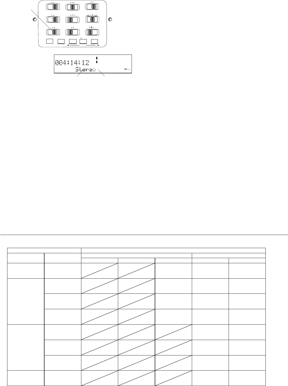
14. INPUT button
The INPUT button lets you
select the audio input and
audio channels for recording.
When the INPUT LOCK switch (a) is at OFF,
press and release the INPUT button to tab
through the input choices. When the desired
input is displayed, switch the INPUT LOCK
switch (a) to ON.
14
ALLOFFSINGLE
R
AUDIO OUT
L
STEREO
FLAT
-20dB0dB
MIC ATTEN
REPEAT
EDL PLAY
ON
OFF MANUALALC
LIMITER
LEVEL CONT.
ANC
INPUT LOCK
ONOFF
PRE REC
ONOFF
MONITOR
FILESOURCE
EDIT
INPUT A-B REPEAT MARK
a
MIC
-dB
00 40 20 12 6 2 0 over
-dB
R
L
REMAINREC TIME
- 17 -
Example
display
Stereo* MIC
*The stereo or mono mode displayed and recorded depends
on the St Mode and Mono Mode menu settings.
Note:
The PMD671 'listens' only to the selected input. For example
if the input selected is LINE input, and no input source is
connected to the LINE IN jacks, the PMD671 will record
silence.
What the input selections do:
Selects the input device(s)
The input selection allows you to choose which
input(s) the PMD671 uses for recording. You
must select the Preset parameters that are
appropriate to the input. The PMD671 will
record with the Rec parameters you select, even
if they are inappropriate for the input. You can
use the default Presets for a quick and easy way
to set up for recording. Use Preset 1 for Stereo
recording using mic or line inputs.
Use Preset 2 when using the internal micro-
phone. Use Preset 3 for digital input.
Input device(s) and channels:
Stereo with MIC input
The microphone connected to the L MIC IN XLR
jack is recorded on the Left channel. The micro-
phone connected to the R MIC IN XLR jack is
recorded on the Right channel.
L-Ste with INT MIC input
Mono audio input from the internal microphone is
recorded on the Left Channel, and the same
audio input is recorded on the Right Channel as a
"stereo" file.
Stereo with LINE input
Audio input from the L LINE IN jack is recorded
on the Left channel.
Audio input from the R LINE IN jack is recorded
on the Right channel.
Digi-IN
Digital audio data at 44.1kHz, 48kHz or 96kHz
input through the DIGITAL IN jack can be re-
corded. Digital input always includes two chan-
nels. They are recorded as Left and Right stereo
channels.
Mono with MIC, INT MIC or LINE input
The input from the Left channel or internal micro-
phone is recorded as a mono file.
Menu Selection
INPUT Button
Selection
input (s)
connected
St. Mode Mono Mode
Stereo L-Stereo 0-20db Mono (L CH.) LR Mono (Mix)
INT MIC Internal
Microphone
L
INT MIC
INT MIC
R
L
INT MIC
INT MIC
R
N/A
defaults to L-Stereo INT MIC INT MIC
Line
L&R LINE IN
L
L LINE IN
R LINE IN
R
L
L LINE IN
L LINE IN
R
N/A
defaults to L-Stereo L LINE IN L + R LINE IN
L LINE IN only
L
L LINE IN
—
R
L
L LINE IN
L LINE IN
R
N/A
defaults to L-Stereo L LINE IN L LINE IN
R LINE IN only
L
—
R LINE IN
R
L
—
—
R
N/A
defaults to L-Stereo — R LINE IN
Mic
L&R MIC IN
L
L MIC IN
R MIC IN
R
L
L MIC IN
L MIC IN
R
L
L MIC IN
L MIC IN
(-20db) R
L MIC IN L + R MIC IN
L MIC IN only
L
L MIC IN
—
R
L
L MIC IN
L MIC IN
R
L
L MIC IN
L MIC IN
(-20db) R
L MIC IN L MIC IN
R MIC IN only
L
—
R MIC IN
R
L
—
—
R
L
—
—
R
— R MIC IN
Digi-in DIGITAL IN
L
L DIGI IN
R DIGI IN
R
L
L DIGI IN
R DIGI IN
R
L
L DIGI IN
R DIGI IN
R
L + R DIGI IN L + R DIGI IN
Inputs / channels recorded
- 18 -
ALLOFFSINGLE
R
AUDIO OUT
L
STEREO
FLAT
-20dB0dB
MIC ATTEN
REPEAT
EDL PLAY
ON
OFF MANUALALC
LIMITER
LEVEL CONT.
ANC
INPUT LOCK
ONOFF
PRE REC
ONOFF
MONITOR
FILESOURCE
EDIT
INPUT A-B REPEAT MARK
15 16 17 18
A-B REPEAT
A
TRACK
TIMETRACK
-dB
00 40 20 12 62 0over
-dB
R
L
A-
A-B
TRACK
TIMETRACK
-dB
00 40 20 12 6 2 0 over
-dB
R
L
A-B
15. A-B REPEAT button
While in playback, press and
release to start point A to point
B repeat playback.
A-B Repeat playback
Point A (starting point) is set when the A-B RE-
PEAT button is pressed and released. The next
press and release sets point B (ending point).
Playback repeats between A and B.
Note:
You can use the -/F.REV or F.FWD/+ buttons
between setting the A and B points.
You cannot use the TRACK JUMP forward or reverse
buttons.
You can pause during A-B repeat playback by
pressing and releasing the PLAY/PAUSE button
. Resume A-B playback by pressing the
PLAY/PAUSE button again.
Exit and cancel A-B repeat by pressing the STOP
button or pressing the A-B REPEAT button.
Example display
when an A point
has been set.
Example display
during A-B repeat.
Note:
For other methods of repeat playback, see the REPEAT
switch and/or EDL A-B looping.
MARK
EDIT
MARK
TIMETRACK
-dB
00 40 20 12 62 0over
-dB
R
L
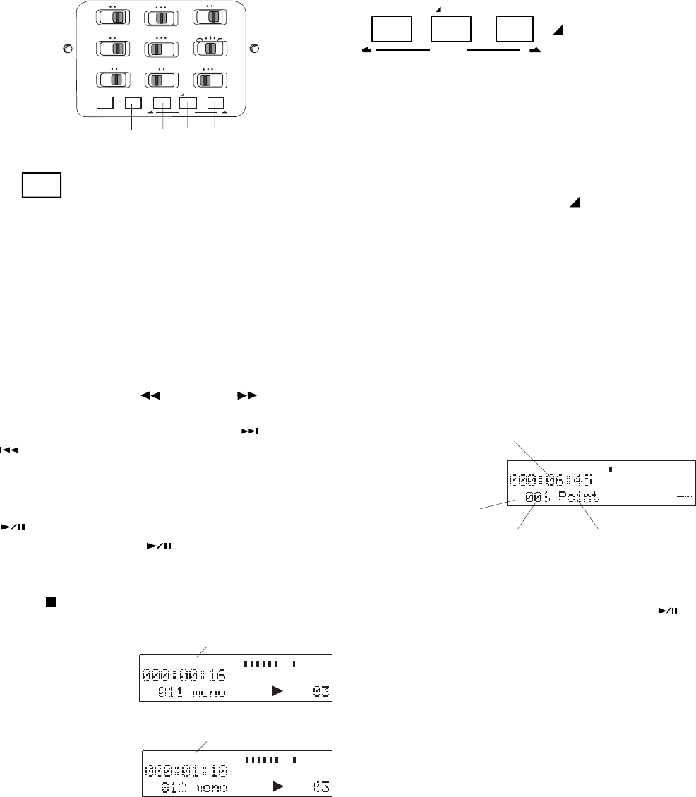
16, 17, 18. MARK/
EDIT buttons
This button group
controls EDL Marks and Editing functions.
EDL Marks
Mark functions: manually adding and locating
Marks.
Adding EDL Marks
Press and release the MARK/ EDIT button
during pause, recording, or playback to add an
EDL Mark. During recording, adding an EDL
Mark introduces an audible click in the recording
when using the internal microphone.
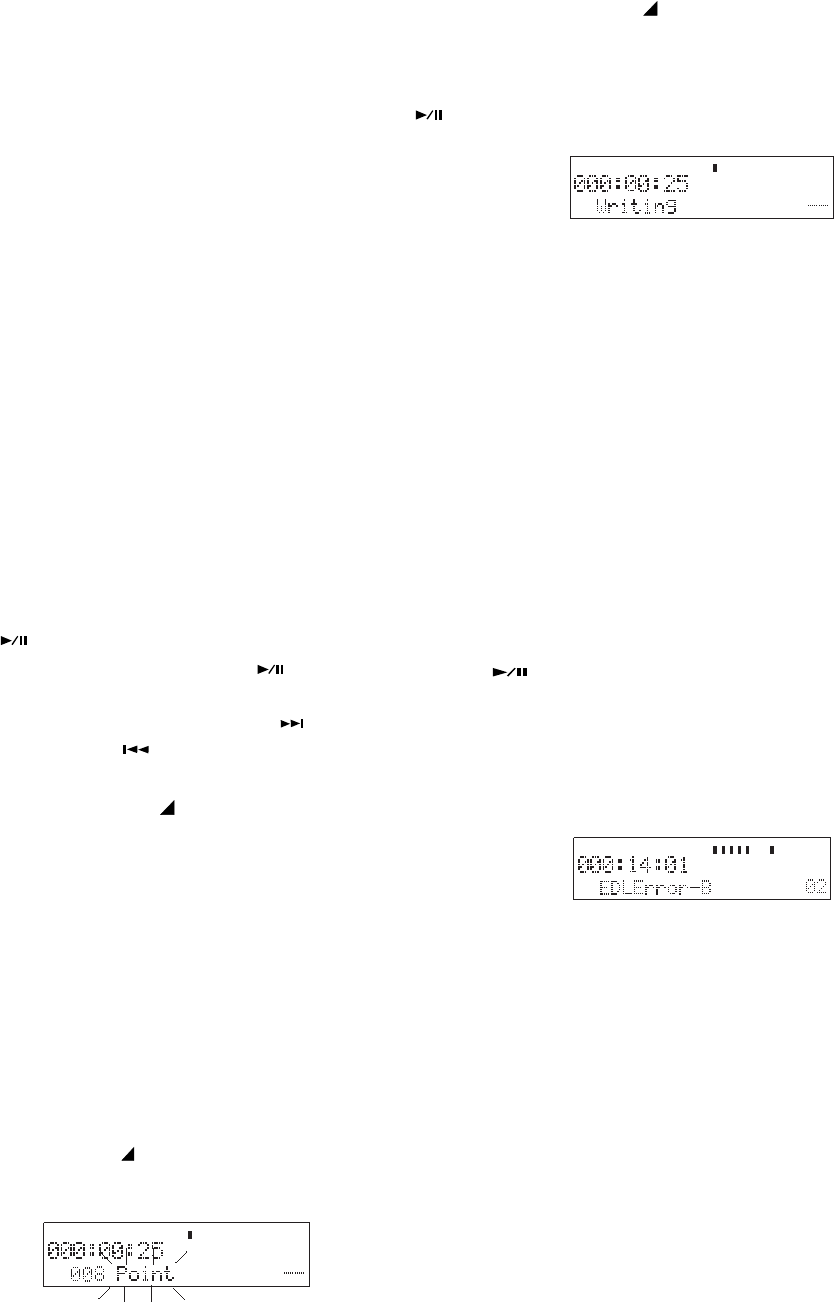
Locating EDL Marks
From Stop, press and release the Mark forward
button (18) or Mark reverse button (16) to tab
through the EDL marks on the CF card.
Example display.
EDL Mark location as recording time
from the beginning of the track.
EDL Mark
number EDL Mark type
MARK dis-
played (instead
of TRACK)
To start playback from the displayed EDL Mark,
press and release the PLAY/PAUSE button .
MARK
TIMETRACK
-dB
00 40 20 12 6 2 0 over
-dB
R
L
- 19 -
Skip
An EDL Mark changed to 'Skip' will be skipped
during EDL playback (playback with EDL PLAY
switch at ON). Playback will skip to the beginning
of the next EDL Mark.
A skipped EDL recording is not erased. The
recording is still on the CF card. The skipped EDL
recording will play if the EDL PLAY switch is at
OFF. You can change the type later.
EDL A-B looping
To playback an EDL A-B loop, press the PLAY/
PAUSE button to begin playback, then press
and release the A-B REPEAT button.
If there is an error, for example there is an EDL
Mark of type Loop_A but no EDL Mark of type
Loop_B, an error message is displayed.
Only one EDL A-B loop can programmed. When
a 'Loop_A' or 'Loop_B' exists on a CF card and
another is created, the old mark automatically
changes to a 'Skip'.
Erase
When an EDL mark is erased, the remaining EDL
marks are automatically renumbered from 1
through the number of EDL marks on the CF
card.
TRACK
TIMETRACK
-dB
00 40 20 12 62 0over
-dB
R
L
Example
display
Edit functions: editing EDL Marks to create
custom playback sequences, erasing and renum-
bering Tracks, and formatting the CF card.
Custom playback sequences
EDL Marks are numbered consecutively from
001 and automatically renumbered when an
EDL Mark is added or erased. Playback is also
consecutive from the point that playback begins.
EDL Mark custom playback can:
Skip playback from the beginning of a 'Skip' EDL
Mark to the beginning of the next EDL Mark.
A-B loop from a 'Loop_A' EDL Mark to a 'Loop_B'
EDL Mark.
EDL Marks are not automatically placed at the
beginning of tracks. If you want your custom
playback sequence to include track beginning
points, add EDL Marks to coincide with track
beginning points:
a. Start playback by pressing and releasing
PLAY/Pause , and then pause playback
by pressing and releasing PLAY/Pause
again.
b. Press and release TRACK JUMP forward
or TRACK JUMP reverse until the de-
sired track number is displayed.
c. Press and release the MARK/ EDIT button.
Editing EDL Marks:
All EDL Marks are initially entered as 'Point'
marks.
From Stop display the EDL Mark by pressing and
releasing the Mark forward button (18) or Mark
reverse button (16) to tab through the EDL marks
on the CF card.
When the EDL mark to be edited is displayed,
press and release the MARK/ EDIT button. The
current EDL Mark type will be flashing.
Writing will be displayed briefly, and the PMD671
will return to stop mode.
MARK
TIMETRACK
-dB
00 40 20 12 6 2 0 over
-dB
R
L
Example
display
Press and release the MARK/ EDIT button to
tab through the EDL Mark types: Point, Skip,
Loop_A, Loop_B and Erase. When the type you
want is flashing, press and release the ENTER
button .
- 20 -
MARK
EDIT
Renumber is flash-
ing in the display.
While Renumber is flashing (3 seconds) press
and release the ENTER button . (Or press
and release the STOP button to cancel.)
ENTER button to confirm.
ing will increase to 100%.
Renumber is flash-
ing in the display.
While Renumber is flashing (3 seconds) press
and release the MARK/ EDIT button again.
TrkERASE is flash-
ing in the display.
While TrkERASE is flashing (3 seconds) press
and release the ENTER button .
Renum OK? will
be flashing. Press
and release the
EXECUTING will be
displayed, and the
percentage execut-
display will return to stop mode.
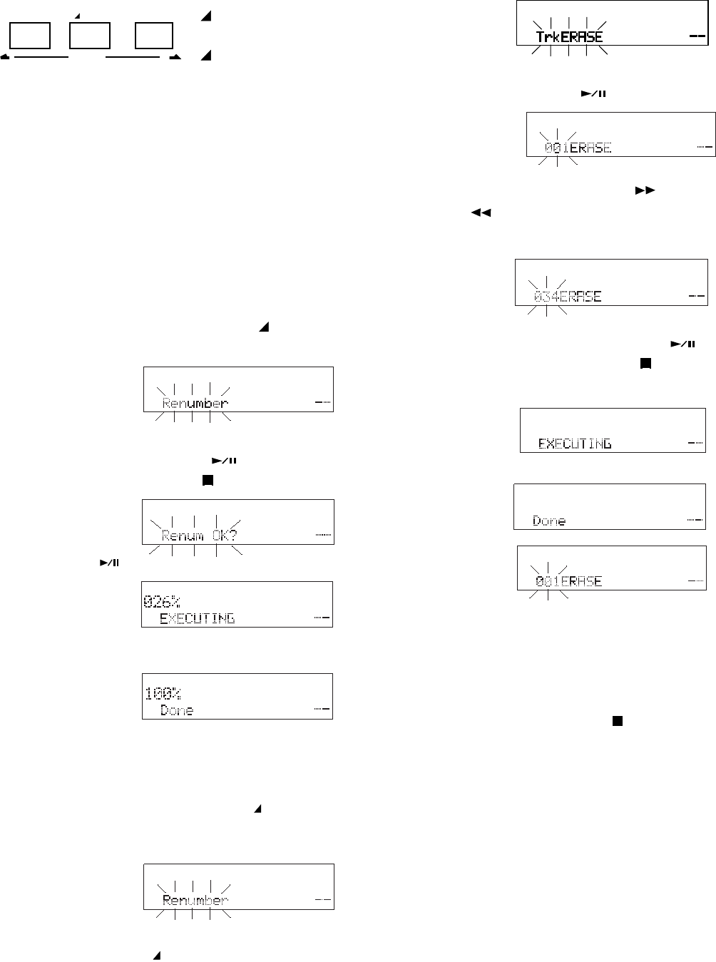
How to erase tracks
From stop, press and hold the MARK/ EDIT
button for about 2 seconds to enter Edit mode.
100% done will be
displayed momen-
tarily. The
PMD671 and the
How to renumber tracks
If you have erased tracks from the CF card it is
easier to locate recordings if the tracks are
renumbered.
EDIT button
Press and hold the
EDIT button for
about 2 seconds to
enter Edit mode.
Edit mode
Edit mode includes: Renumber (renumber
tracks), TrkERASE (erase a track), TrkMkERASE
(erase an EDL mark), AllMkERASE (erase all
EDL marks), FORMAT (format the CF card), and
CARD CHECK.
From stop, press and hold the MARK/ EDIT
button for about 2 seconds to enter Edit mode.
Track number is
flashing in the
ERASE display.
Press and release the F.FWD/+ button or the
-/F.REV button to select the track number
you want to erase.
Example track
34.
While the track to be erased is flashing (3 sec-
onds), press and release the ENTER button .
(Or press and release the STOP button to
cancel.)
EXECUTING will be
displayed momen-
tarily.
Done will be dis-
played momentarily.
The PMD671 and
the display will
return to the first
track so you can choose to erase another track.
The recording time (file space on the CF card)
used by the erased track is available for record-
ing.
Press and release the STOP button to exit.
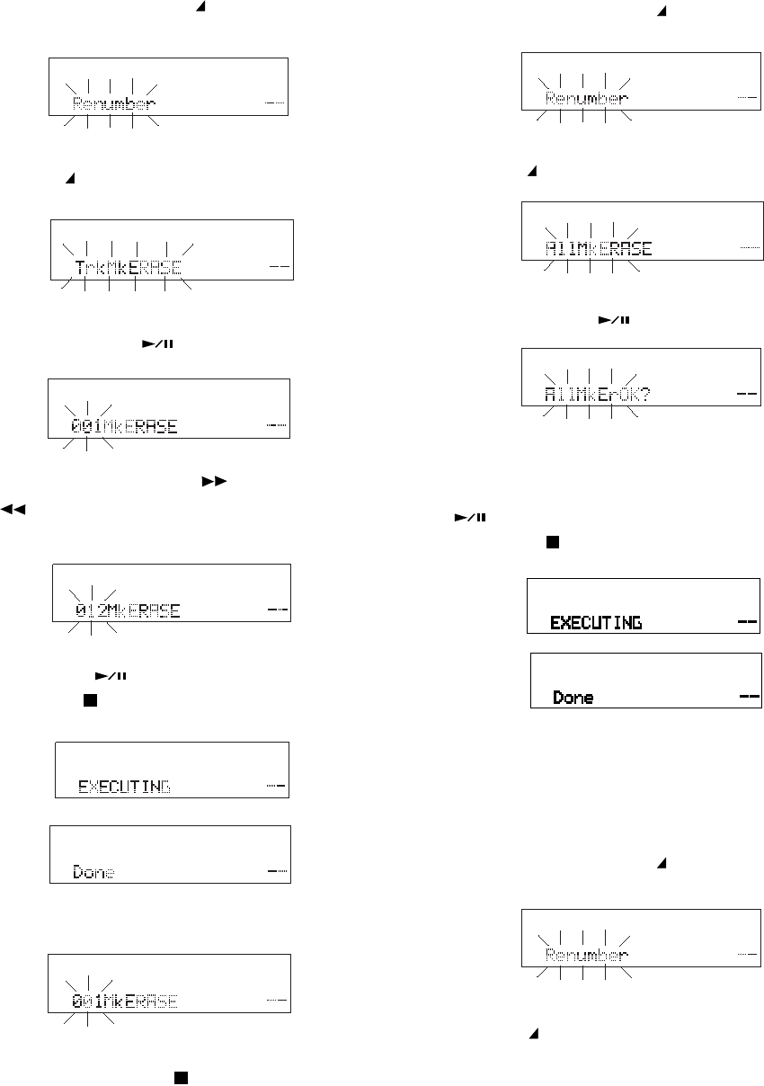
While the display is flashing (3 seconds) press
and release the MARK/ EDIT button two more
times.
Renumber is flash-
ing in the display.
How to erase all EDL marks within one track
From stop, press and hold the MARK/ EDIT
button for about 2 seconds to enter Edit mode.
TrkMkERASE is
flashing in the display.
While TrkMkERASE is flashing (3 seconds) press
and release the ENTER button .
Press and release the F.FWD/+ button or the
-/F.REV button to select the track that
contains the EDL Marks to erase.
Example to erase all
EDL marks in Track
12.
While the track number is flashing, press and
release the ENTER button . (Or press and
release the STOP button to cancel.)
EXECUTING
will be displayed
momentarily.
Done will be
displayed mo-
mentarily.
The PMD671 and the display will return to the
- 21 -
Track number is
flashing in the
ERASE display
first track, so you
can choose an-
other track to
erase its EDL
marks.
How to erase all EDL marks
From stop, press and hold the MARK/ EDIT
button for about 2 seconds to enter Edit mode.
Renumber is flash-
ing in the display.
While the display is flashing (3 seconds) press
and release the MARK/ EDIT button three more
times.
AllMkERASE is
flashing in the display.
While AllMkERASE is flashing (3 seconds), press
and release the ENTER button .
AllMkErOK? is
flashing in the
display.
The display asks you to confirm that you want to
erase all EDL Marks on the CF card. While
AllMkErOK? is flashing, press and release the
ENTER button to confirm. (Or press and
release the STOP button to cancel.)
EXECUTING will be
displayed momen-
tarily.
Done will be dis-
played momentarily.
The PMD671 and the display will return to stop
mode.
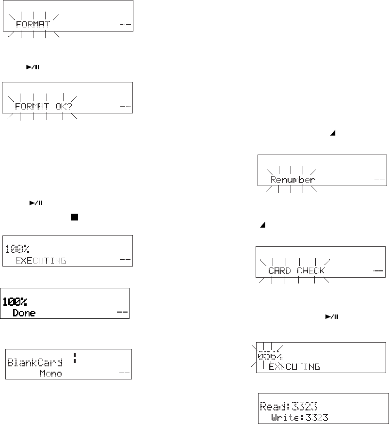
How to format a CF card
From stop, press and hold the MARK/ EDIT
button for about 2 seconds to enter Edit mode.
Renumber is flash-
ing in the display.
While the display is flashing (3 seconds) press
and release the MARK/ EDIT button four more
times.
Press and release the STOP button to exit.
LINE
-dB
00 40 20 12 6 2 0 over
-dB
R
L
FORMAT is flash-
ing in the display.
While FORMAT is flashing (3 seconds), press and
release the ENTER button .
FORMAT OK? is
flashing in the
display.
The display asks you to confirm that you want to
format the CF card. Formatting the CF card will
erase all recordings on the card.
While FORMAT OK? is flashing, press and
release the ENTER button to confirm. (Or
press and release the STOP button to cancel.)
EXECUTING will be
displayed momen-
tarily.
Done will be dis-
played momentarily.
The PMD671 returns to stop mode.
BlankCard will be
displayed.
The CF card formats used by the PMD671 are
Windows compatible. You can copy audio files
using a Windows compatible computer* that can
read a CF card or be connected via the USB port.
*Or a Macintosh computer that can recognize Windows
compatible removable drives.
CF cards with less than 2 GB capacity are auto-
matically formatted FAT16 (FAT = File Allocation
Table).
CF cards with 2 - 8 GB capacity are automatically
formatted FAT32.
The maximum CF card that can be formatted in
the PMD671 is 8 GB. If larger cards are used,
please format in your computer.
- 22 -
How to check a CF card (CARD CHECK)
Although rare, manufacturing defects in CF cards
occasionally prevent a CF card from being able
to read and write at the speeds required by the
PMD671. CARD CHECK does a sample read/
write to check if a CF card has problems. If a
CARD CHECK fails, you can usually return the
CF card for a replacement.
From stop, press and hold the MARK/ EDIT
button for about 2 seconds to enter Edit mode.
Renumber is flash-
ing in the display.
While the display is flashing (3 seconds) press
and release the MARK/ EDIT button five more
times.
CARD CHECK is
flashing in the
display.
While CARD CHECK is flashing (3 seconds)
press and release the ENTER button .
EXECUTING will
be displayed and
the percentage will
go to 100%.
Read: and Write:
numbers will be
displayed. If the
read and write
numbers are the same, the CF card check is
successful.
Note:
The number times 2 equals the actual read and write speed
in kbps. For the example card, the total speed of the
PMD671 and CF card was thus 6646 kbps. To read and
write audio at 24-bit 96 kHz requires at least 4680 kbps.
Example display
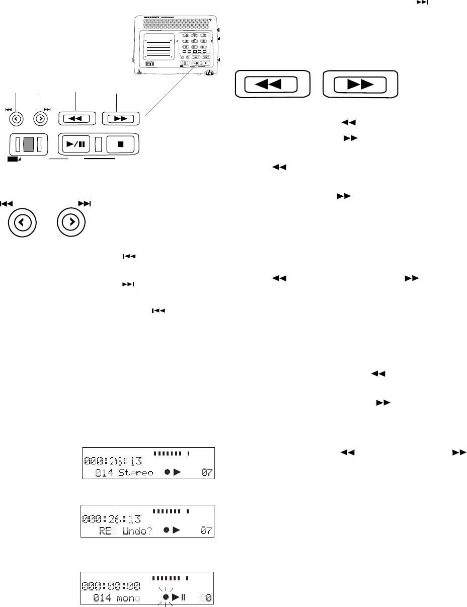
20. TRACK JUMP forward button
During playback, press and release to jump to the
next track. If pressed while playing the last track,
playback jumps to the first track on the CF card.
21. - /F.REV button
22. F.FWD/+ button
During playback, press and hold the -/F.REV
button to Fast Reverse and, do an audible
search in the reverse direction. Press and hold
the F.FWD/+ button to Fast Forward and, do
a 2X speed audible search in the forward direc-
tion. Release to return to normal forward play-
back.
During play pause, press and hold the -/F.REV
button or the F.FWD/+ button to Fast
Reverse or Fast Forward quickly. The Fast
Reverse or Fast Forward is at 10X speed for
three seconds, then it automatically speeds up to
140X speed.
During Editing and Menu functions, press and
release the -/F.REV button to increment a
parameter in the - direction, and press and
release the F.FWD/+ button to increment a
parameter in the + direction.
Notes:
• If the -/F.REV button or the F.FWD/+ button is
held past the beginning or end of a track, the Fast
Reverse or Fast Forward will continue onto the previous
or next track.
• If REPEAT SINGLE or REPEAT ALL is on, the Fast
Reverse or Fast Forward will follow the repeat order.
• The buttons do not function in EDL playback or EDL A-B
repeat.
- 23 -
SOLID STATE RECORDER PMD671
POWER
MIC ATTEN
0dB -20dB
FLAT
ANC
LEVEL CONT.
LIMITER
ALC MANUAL
OFF ON
EDL PLAY
STEREO
L
AUDIO OUT
R
SOURCE FILE
MONITOR
OFF ON
PRE REC
MARK
A-B REPEAT
INPUT
EDIT
SINGLE
OFF ALL
OFF ON
INPUT LOCK
TRACK JUMP
MARGIN RESET
REC
UNDO
MENU/STORE ENTER CANCEL
PLAY / PAUSE STOP
USB
-
/
REW FWD
/
+
TRACK JUMP
MARGIN RESET
REC
UNDO
MENU/STORE ENTER CANCEL
PLAY / PAUSE STOP
USB
-
/
F.REV F.FWD
/
+
19
TRACK JUMP
REC
UNDO
TRACK
TIMETRACK
LINE
-dB
00 40 20 12 6 2 0 over
-dB
R
L
TRACK
TIMETRACK
MIC
INT -dB
00 40 20 12 62 0over
-dB
R
L
TRACK
TIMETRACK
MIC
INT -dB
00 40 20 12 62 0over
-dB
R
L
Controls and Connections
Top continued
19, 20. TRACK
JUMP buttons
TRACK JUMP reverse button
REC UNDO button
TRACK JUMP forward button
19. TRACK JUMP reverse button
During playback, press and release to jump to the
previous track. If pressed while playing the first
track, playback jumps to the last track on the CF
card.
19. REC UNDO button
During recording, press and release twice to undo
(erase) the recording and pause recording at the
beginning of the track.
Example display
during record.
Example display for
3 seconds after
REC UNDO button
is pressed.
Example if REC
UNDO button is
pressed again
within the 3 sec-
onds.
Recording is at REC pause at the beginning of
the track.
20 21 22
-
/
F.REV F.FWD
/
+
- 24 -
SOLID STATE RECORDER PMD671
POWER
MIC ATTEN
0dB -20dB
FLAT
ANC
LEVEL CONT.
LIMITER
ALC MANUAL
OFF ON
EDL PLAY
STEREO
L
AUDIO OUT
R
SOURCE FILE
MONITOR
OFF ON
PRE REC
MARK
A-B REPEAT
INPUT
EDIT
SINGLE
OFF ALL
OFF ON
INPUT LOCK
TRACK JUMP
MARGIN RESET
REC
UNDO
MENU/STORE ENTER CANCEL
PLAY / PAUSE STOP
USB
-
/
REW FWD
/
+
TRACK JUMP
MARGIN RESET
REC
UNDO
MENU/STORE ENTER CANCEL
PLAY / PAUSE STOP
USB
-
/
F.REV F.FWD
/
+
MIC
INT
TRACK
TIMETRACK
-dB
00 40 20 12 62 0over
-dB
R
L
level margin
MENU/STORE
MARGIN RESET
USB
23
SOLID STATE RECORDER PMD671
POWER
MIC ATTEN
0dB -20dB
FLAT
ANC
LEVEL CONT.
LIMITER
ALC MANUAL
OFF ON
EDL PLAY
STEREO
L
AUDIO OUT
R
SOURCE FILE
MONITOR
OFF ON
PRE REC
MARK
A-B REPEAT
INPUT
EDIT
SINGLE
OFF ALL
OFF ON
INPUT LOCK
TRACK JUMP
MARGIN RESET
REC
UNDO
MENU/STORE ENTER CANCEL
PLAY / PAUSE STOP
USB
-
/
REW FWD
/
+
TRACK JUMP
MARGIN RESET
REC
UNDO
MENU/STORE ENTER CANCEL
PLAY / PAUSE STOP
USB
-
/
F.REV F.FWD
/
+
a b
d c
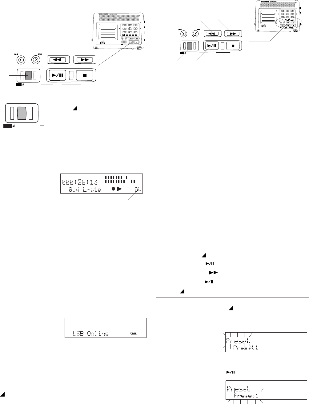
Controls and Connections
Top continued
MARGIN RESET button
During record, press and release to reset the
peak level margin.
Example display
with level margin at
OV before pressing
the MARGIN RE-
SET button.
The level margin displays the highest level
achieved since the track began, or the MARGIN
RESET button was pressed and released. OV
indicates a margin over 0dB.
USB button
Connects the CF card via the USB port to a
connected device (usually a computer).
From power off, press and hold the USB button
while you slide the PMD671's POWER switch to
the right.
This display
appears.
The CF card in the PMD671 appears as an
external drive on a connected computer.
Power off to disconnect.
See page 51, How to connect via the USB port.
MENU/STORE button
Press and hold for about 2 seconds to enter
menu mode.
Press and release during menu operations to
store the changed values.
Menu operations
Menu operations let you fine tune how the
PMD671 is set up, including the recording pa-
rameters for your specific recording situation.
The PMD671 is always recording using Preset1,
2 or 3. To modify the recording setup, you modify
one of those three presets.
The Menu procedure starts with selecting one of
the Presets, then modifying either the settings
within that Preset, or the General settings for
Date and time, date format, beep and/or battery
type.
1. Press and hold the MENU/STORE button
(a) for about 2 seconds. Preset will appear
(flashing) in the display.
Example
display
Press ENTER ......save & switch to next item
Press MENU/STORE .....................save & exit
Select Preset
Quick instructions
Press & hold MENU/STORE 2 sec ....... Preset
Press ENTER ................................... Preset#
Press F.FWD/+ ..................................... set #
23. MARGIN RESET/
USB MENU/STORE
buttons
Several functions depending
on state of the PMD671.
2. While Preset is flashing, press and release
the ENTER button (b).
The flashing
switches to the
Preset choice.
continues
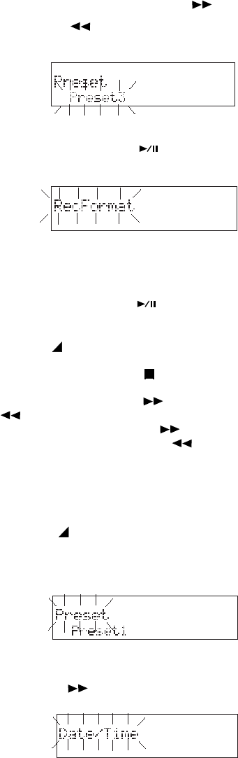
- 25 -
Example display
3. Press and release the F.FWD/+ button (c)
or the -/F.REV button (d) to tab through
Preset1, Preset2 and Preset3.
4. When the correct choice is displayed, press
and release the ENTER button (b) to
select your Preset choice.
The display
switches to
RecFormat flash-
You can:
• Press and release the ENTER button to switch to
editing the Rec Format parameters of your Preset
choice.
• Press and release the MENU/STORE button to store
your Preset choice and exit Menu mode.
• Press and release the CANCEL button to exit menu
mode without changing your Preset.
• Press and release the F.FWD/+ button or the -/
F.REV button to change menu settings that are not
specific to a Preset. (The F.FWD/+ button switches
to MONITOR Mode, and the -/F.REV button
switches to Default.)
Menu settings
1. Press and hold the MENU/STORE button
(a) for about 2 seconds. Preset will appear
(flashing) in the display.
Example display
2. While Preset is flashing, press and release
the F.FWD/+ button .
The display
switches to Date/
Time flashing.
The Menu choices are:
General settings
(common to Presets 1, 2 and 3)
Date/Time – For setting or changing the Date
and Time associated with when an audio
track (file) was created.
Date Form – For selecting the date order.
Beep – Turn the beep on or off.
A.PowOff – Enable or disable the Automatic
Power Off feature.
Batt type – Set the battery type.
Preset - Choose 1, 2 or 3.
Within Preset choice:
RecFormat – For setting or changing the re-
cording compression algorithm, bit rate, sam-
pling frequency, audio file type, and if one or two
input channels are to be recorded.
RAW Mode - Choose Monitor or TimeShft.
Verify - Set the automatic recording verify
feature on or off.
PupPreRec - Set the power up pre record
feature on* or off.
*If PupPreRec is on in the preset menu, AutoTrk will not
work, even if it is set to on.
St Mode - If Stereo is set in RecFormat this sets
how Left and Right input channels are recorded
(Stereo, L-Stereo or 0-20dB).
Mono Mode - If Mono is set in RecFormat this
sets how the source is recorded onto the MONO
channel (Mono or L/R mix mono).
Auto Mark - Turn the automatic EDL mark
feature on or off.
Manual TR – Turn manual track incrementing
feature on or off.
Auto TRK - Turn the automatic track
incrementing feature on or off, and if on, set the
time interval.
SeamlsPly – Turn the Seamless play feature on
or off.
SilentSkp – Turn Silent Skip feature ON, Off or
ON with new track, set the number of seconds
the dB level must meet or exceed the set thresh-
old, and set the dB threshold level.
continues
ing for your Preset choice.
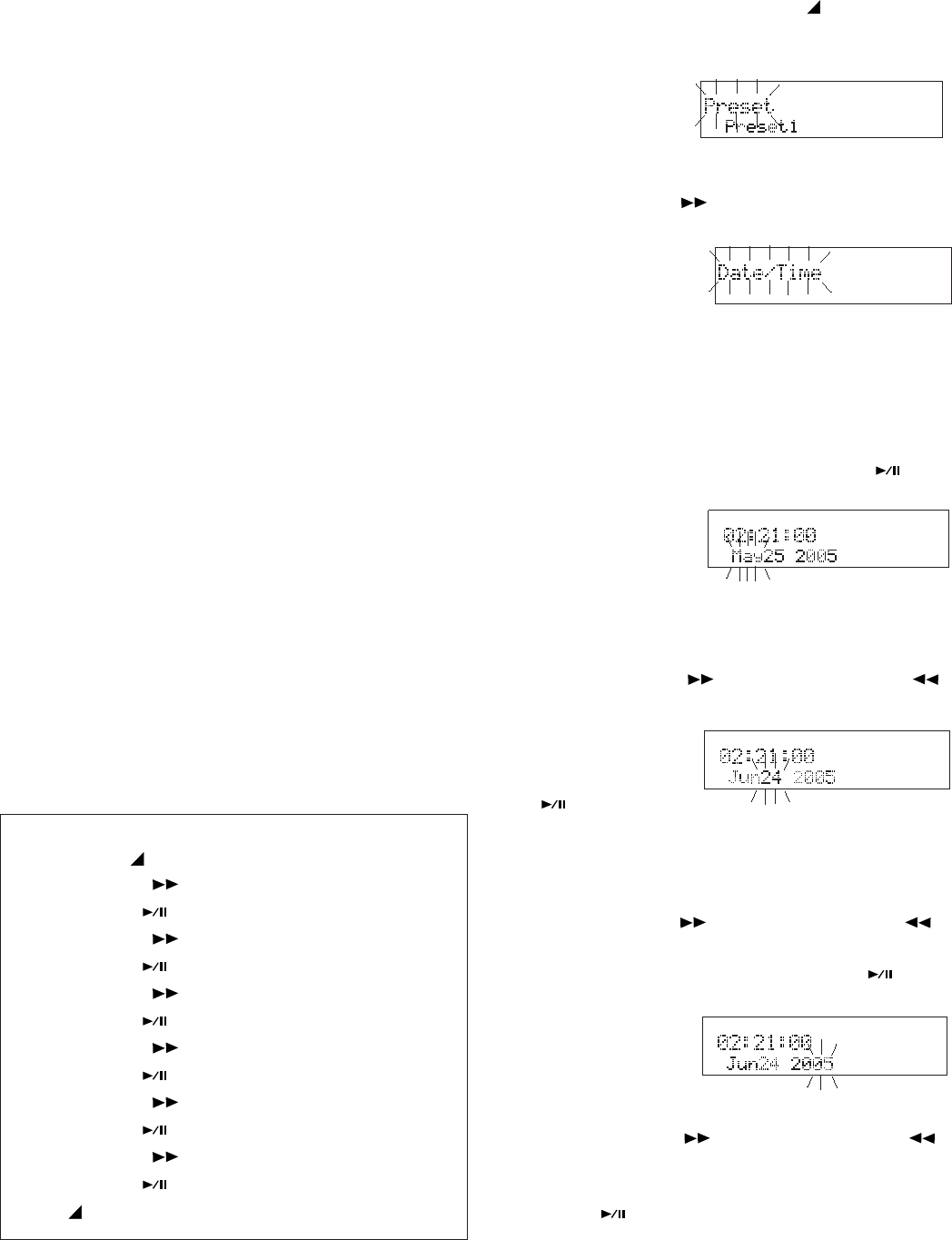
- 26 -
Auto Cue – Turn the Auto Cue feature on or off,
set the number of milliseconds the dB level must
meet or exceed the set threshold, and set the dB
threshold level.
S.Monitor - Turn the Stop Monitor feature on or
off.
SinglePly – Turn the single track play feature on
or off.
Remote – Set the effect of the optional wired
remote contact closure switch plugged into the
REMOTE 1 jack.
ID1Dscrpt – Set the description ID code for
broadcast wave file recordings.
ID2Origin – Set the origin ID code for broadcast
wave file recordings.
ID3OrgRef – Set the origin reference ID code for
broadcast wave file recordings.
Default – Reset all Menu settings to factory
default settings.
How to set or change the Date and time
The date and time are written on each audio track
(file) when the track is started. When an audio
track is viewed on a computer, this date and time
appears as when the file was 'modified'. (US date
format is illustrated.)
The Date/Time
Menu choice will
most likely ap-
pear.
Note
If another Menu choice appears (Date Form, Beep,
A.PowOff, Batt type) press and release the F.FWD/+ button
repeatedly until Date/Time is displayed.
3. Press and release the ENTER button .
The current date
and time informa-
tion will be
displayed with Example display
1. From stop, press and hold the MENU/
STORE button for about 2 seconds. Preset
will appear (flashing) in the display.
Example
display
2. With Preset flashing, press and release the
F.FWD/+ button .
Quick instructions
Press & hold MENU/STORE 2 sec ....... Preset
Press F.FWD/+ ............................. Date/Time
Press ENTER ..................................... month
Press F.FWD/+ repeatedly ..... correct month
Press ENTER ......................................... day
Press F.FWD/+ repeatedly ......... correct day
Press ENTER ........................................ year
Press F.FWD/+ repeatedly ........ correct year
Press ENTER ........................................ hour
Press F.FWD/+ repeatedly ........ correct hour
Press ENTER .................................... minute
Press F.FWD/+ repeatedly .... correct minute
Press ENTER ............................... Date/Time
Press MENU/STORE .................... store & exit
the month flashing.
4. With the month flashing press and release the
F.FWD/+ button or the -/F.REV button
to tab through the months. When the month
Example display
is correct, press
and release the
ENTER button
.
The day will be flashing.
5. With the day flashing press and release the
F.FWD/+ button or the -/F.REV button
to tab through days. When the day is correct,
press and release the ENTER button .
The year will be flashing.
Example
display
6. With the year flashing press and release the
F.FWD/+ button or the -/F.REV button
to tab through years (2005 - 2099). When the
year is correct, press and release the ENTER
button .
PM
PM
PM
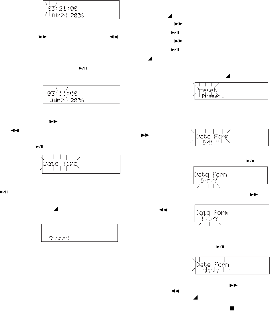
- 27 -
PM
PM
Example
display.
7. With the hour flashing, press and release the
F.FWD/+ button or the -/F.REV button
to tab through hours. AM, PM will change
when you pass 12, check that it is correct.
When the hour and AM/PM is correct, press
and release the ENTER button .
The minute will be flashing.
Example
display
8. With the minute flashing, press and release
the F.FWD/+ button or the -/F.REV
button to tab through minutes. When the
minute is correct*, press and release the
ENTER button .
Date/Time will
be flashing.
*To set time correct to the second, set to the next minute and
wait for that minute to begin before pressing the ENTER
button .
The hour will be flashing.
date and/or time,
Stored will be
displayed briefly.
9. Press and release the MENU/STORE
button. If you have made changes to the
The display will return to stop mode.
Note:
The date and time settings will remain for about 5 years if
the AC Adapter is not plugged in and no batteries are
installed.
Date Form
The Date Form is the date order month/day/year
or day/month/year.
The US default is M/D/Y (month/day/year).
The Europe default is D/M/Y (day/month/year).
How to set or change the Date Form
Quick instructions
Press & hold MENU/STORE 2 sec ....... Preset
Press F.FWD/+ 2X....................... Date Form
Press ENTER ...................... M/D/Y or D/M/Y
Press F.FWD/+ .................... M/D/Y or D/M/Y
Press ENTER .............................. Date Form
Press MENU/STORE .................... store & exit
1. From stop, press and hold the MENU/
STORE button
for about 2
seconds.
Preset will appear (flashing) in the display.
2. With Preset flashing, press and release the
F.FWD/+ button
repeatedly
until Date Form
is displayed.
3. Press and release the ENTER button
again. The M/D/
Y choice will
flash.
4. Press and release the F.FWD/+ button or
the -/F.REV
button to
toggle between
M/D/Y and D/M/Y.
5. When the desired form appears, press and
release the ENTER button .
The display
returns to Date
Form flashing.
You can:
• Press and release the F.FWD/+ button or the -/
F.REV button to tab to another menu choice, or
• Press and release the MENU/STORE button to
write the menu changes and return to stop mode, or
• Press and release the CANCEL button to cancel all
menu changes and return to stop mode.
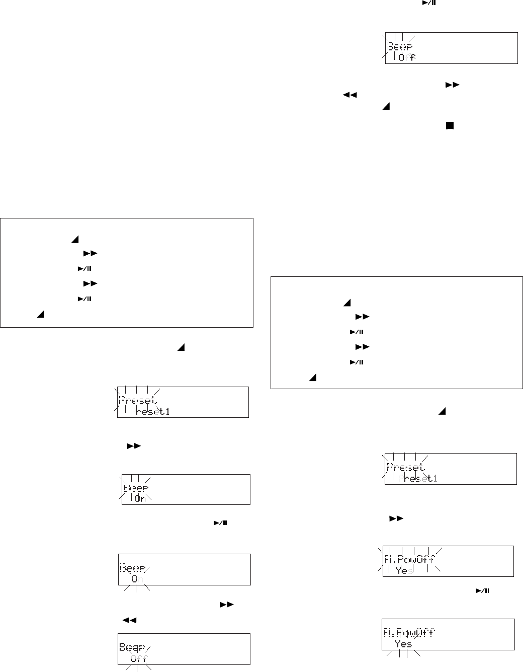
- 28 -
Beep
When battery charge can provide no more than
1-3 minutes of recording or playback and Beep is
set to On, the CHARGE indicator, REC indicator
and the battery indicator in the display will flash,
and the PMD671 will beep through the head-
phones or speaker.
If the PMD671 is not operated for 30 minutes
during stop or play pause, power can be auto-
matically shut off to conserve battery life. (See
A.PowOFF.) If A.PowOFF is set to Yes, and Beep
is set to ON, the PMD671 will beep to alert you
that the power is shutting off.
Default is Beep On.
How to set or change the Beep
Example
display
1. From stop, press and hold the MENU/
STORE button for about 2 seconds. Preset
will appear (flashing) in the display.
Quick instructions
Press & hold MENU/STORE 2 sec ....... Preset
Press F.FWD/+ 3X................................ Beep
Press ENTER ................................ Off or On
Press F.FWD/+ .............................. Off or On
Press ENTER ....................................... Beep
Press MENU/STORE .................... store & exit
2. While Preset is flashing, press and release
the F.FWD/+ button repeatedly until Beep
is displayed.
3. Press and release the ENTER button .
The On-Off choice will flash.
4. Press and release the F.FWD/+ button or
the -/F.REV button to toggle between
On and Off.
5. When the desired state appears press and
release the ENTER button .
The display returns to Beep flashing.
You can:
• Press and release the F.FWD/+ button or the -/
F.REV button to tab to another menu choice, or
• Press and release the MENU/STORE button to write
the menu changes and return to stop mode, or
• Press and release the CANCEL button to cancel all
menu changes and return to stop mode.
Quick instructions
Press & hold MENU/STORE 2 sec ....... Preset
Press F.FWD/+ 4X......................... A.PowOff
Press ENTER ................................Yes or No
Press F.FWD/+ ..............................Yes or No
Press ENTER ................................ A.PowOff
Press MENU/STORE .................... store & exit
Automatic Power Off
If the PMD671 is not operated for 30 minutes
during stop or play pause, power is automatically
shut off to conserve battery life when A.PowOff is
set to Yes.
Default is A.PowOFF Yes
How to set or change Automatic Power Off
2. While Preset is flashing, press and release
the F.FWD/+ button repeatedly until
A.PowOff is displayed.
3. Press and release the ENTER button .
The Yes-No choice will flash.
1. From stop, press and hold the MENU/
STORE button for about 2 seconds. Preset
will appear (flashing) in the display.
Example
display
Example
display
Example
display
Example
display
Example
display
Example
display
Example
display
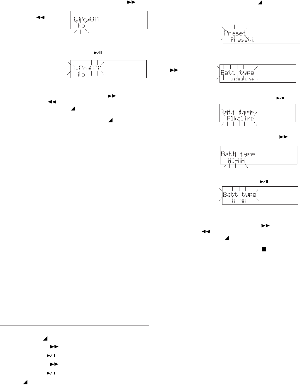
- 29 -
4. Press and release the F.FWD/+ button or
2. With Preset flashing, press and release the
F.FWD/+ button
repeatedly
until Batt type is
displayed.
3. Press and release the MENU button .
The Batt type
choice will flash.
4. Press and release the F.FWD+ button to
tab through the
Battery type
choices.
1. From stop, press and hold the MENU/
STORE button for about 2 seconds. Preset
will appear (flashing) in the display.
the -/F.REV
button to
toggle between
Yes and No.
5. When the desired state appears, press and
release the ENTER button .The display
returns to
A.PowOff
flashing.
You can:
• Press and release the F.FWD/+ button or the -/
F.REV button to tab to another menu choice, or
• Press and release the MENU/STORE button to write
the menu changes and return to stop mode, or
• Press and release the CANCEL button to cancel all
menu changes and return to stop mode.
Battery Type
The PMD671 can operate on 8 standard AA size
Alkaline, Ni-Cd or Ni-MH batteries.
An optional Ni-Cd battery pack (Model RB1100
available from Marantz Professional) will be
charged by the built-in charger when the AC
adaptor is plugged in.
An optional Ni-MH battery pack (Model RB1651
available from Marantz Professional) will be
charged by the built-in charger when the AC
adaptor is plugged in.
The Battery Type setting is used for the battery
indicator in the display and "Low Battery" warn-
ing. If the setting does not match installed batter-
ies the PMD671 will not show the appropriate
battery status.
Example
display
5. With the desired battery type displayed, press
and release the ENTER button .The
display returns to
Batt type flash-
ing.
You can:
• Press and release the F.FWD/+ button or the -/
F.REV button to tab to another menu choice, or
• Press and release the MENU/STORE button to write
the menu changes and return to stop mode, or
• Press and release the CANCEL button to cancel all
menu changes and return to stop mode.
Default is Alkaline.
How to set or change Battery Type
Quick instructions
Press & hold MENU/STORE 2 sec ....... Preset
Press F.FWD/+ 5X.......................... Batt type
Press ENTER ............... battery type flashing
Press F.FWD/+ ........... tab thru battery types
Press ENTER ................................. Batt type
Press MENU/STORE .................... store & exit

- 30 -
Rec Format
The PMD671 can record from analog or digital
inputs, on one channel (mono) or two (stereo), in
PCM at 24 or 16 bits, and in MP2 or MP3 com-
pression formats.
For given channels and formats the PMD671 can
record at several bit rates and sample frequen-
cies.
The file extension (.wav, .mpg, .mp3) is set by the
file format chosen (PCM, MP2, MP3) except for
BWF files (Broadcast Wave Format). The BWF
file extension can be either .wav, or .bwf.
As audio quality goes up (more bits, less com-
pression, higher sampling frequency, greater bit
rate), the amount of information recorded in-
creases so the amount of time that can be re-
corded on a CF card of a specific size goes
down. See Recording time chart on page 57.
The PMD671 has a sizeable range of file format
parameter choices available, but it does not
present you with every possible combination.
Your decisions about which File Format param-
eters to use will depend on the quality level you
need for the purpose(s) of your recording versus
limitations in recording time.
Note:
At very high audio quality levels, processor power also
becomes a limitation. The RAW (Read After Write) and Time
Shift features are processor intensive, so in some instances
the MONITOR and Verify features and 24-bit recording
cannot be used simutaneously. See charts on page 14.
The File Format chart below follows the PMD671
File Format menu setting procedure as you read
columns from left to right.
Note
A full size copy of this chart is on page 58.
Rec Format Chart
The RecFormat setting procedure is usually
unnecessary for Digital Input. See page 34. The
following applies to inputs from MIC, LINE IN,
and the Internal mic.
Channel(s)
Choose between Stereo and Mono recording
(two or one channel). For PCM recording, Stereo
is about twice as time intensive as Mono.
Format
Choose between PCM (16 or 24 bit) or a com-
pression format (MP2 or MP3).
Fs (Sampling Frequency)
Choose the Sample Frequency (in kHz).
Bit rate
You can select a bit rate in kilobits per second
(kbps) for a compression format (MP2 or MP3).
File ext. (File extension)
In most cases, you have chosen the file exten-
sion by choosing the Format. If you desire a
BWF file choose between .wav and .bwf for the
file extension.
16 bit
PCM
24 bit
16 bit
mp3/bwf
(80, 64, 40, 32, 24, 16)
24, 22.05, 16
mp3/bwf
(160, 128, 80, 64, 40, 32)
48, 44.1, 32
MP3
mpg/bwf
(192, 128, 96, 64, 48, 32)
48, 44.1, 32
MP2
16, 12, 11.025, 8
48, 44.1, 32, 24, 22.05,
wav/bwf
96, 88.2, 48, 44.1
Mono
BWF ext.
wav/bwfmp3/bwf
mp3/bwf
mpg/bwf
(160, 128, 80, 64, 40, 32)
24, 22.05, 16
(320, 256, 160, 128, 80, 64)
48, 44.1, 32
MP3
(384, 256, 192, 128, 96, 64)
48, 44.1, 32
MP2
PCM
Stereo
24 bit
wav/bwf
16, 12, 11.025, 8
48, 44.1, 32, 24, 22.05,
96, 88.2, 48, 44.1
File ext.
Fs kHz and
(Bit rate kbps)
Audio
Format
Channel(s)
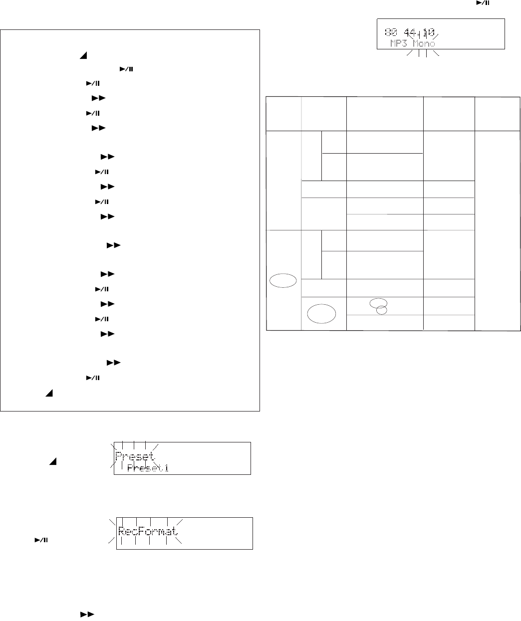
16 bit
PCM
24 bit
16 bit
mp3/bwf
(80, 64, 40, 32, 24, 16)
24, 22.05, 16
mp3/bwf
(160, 128, 80, 64, 40, 32)
48, 44.1, 32
MP3
mpg/bwf
(192, 128, 96, 64, 48, 32)
48, 44.1, 32
MP2
16, 12, 11.025, 8
48, 44.1, 32, 24, 22.05,
wav/bwf
96, 88.2, 48, 44.1
Mono
BWF ext.
wav/bwfmp3/bwf
mp3/bwf
mpg/bwf
(160, 128, 80, 64, 40, 32)
24, 22.05, 16
(320, 256, 160, 128, 80, 64)
48, 44.1, 32
MP3
(384, 256, 192, 128, 96, 64)
48, 44.1, 32
MP2
PCM
Stereo
24 bit
wav/bwf
16, 12, 11.025, 8
48, 44.1, 32, 24, 22.05,
96, 88.2, 48, 44.1
File ext.
Fs kHz and
(Bit rate kbps)
Audio
Format
Channel(s)
- 31 -
kHz
kbps
How to set or change the Rec Format param-
eters.
Quick instructions
Press & hold MENU/STORE 2 sec ....... Preset
Double Click ENTER .................. RecFormat
Press ENTER ...................... Mono or Stereo
Press F.FWD/+ .................... Mono or Stereo
Press ENTER ................. PCM, MP2 or MP3
Press F.FWD/+ ............... PCM, MP2 or MP3
If MP2 or MP3 ................................................khz
Press F.FWD/+ .......................... select khz
Press ENTER .....................................kbps
Press F.FWD/+ ........................ select kbps
Press ENTER ............. select file extension
Press F.FWD/+ .......... mp3, mpg, wav, bwf
If bwf....................................Exten (.bwf, wav)
Press F.FWD/+ .......................... bwf, wav
If PCM ............................................... 24 or 16 bit
Press F.FWD/+ ........................ 24 or 16 bit
Press ENTER .......................................khz
Press F.FWD/+ .......................... select khz
Press ENTER ............. select file extension
Press F.FWD/+ ............................ wav, bwf
If bwf....................................Exten (.bwf, wav)
Press F.FWD/+ .......................... bwf, wav
Press ENTER ............................. RecFormat
Press MENU/STORE .................... store & exit
1. Press and hold
the MENU/
STORE button.
Preset flashing appears.
2. Double click the
ENTER button
so
RecFormat is
flashing.
Note
If another menu item is flashing, press and release the
F.FWD/+ button repeatedly until RecFormat is dis-
played and flashing.
3. Press and release the ENTER button .
Mono or Stereo
will be flashing.
Note
The circled items in the chart below reflect the settings in the
example.
continues
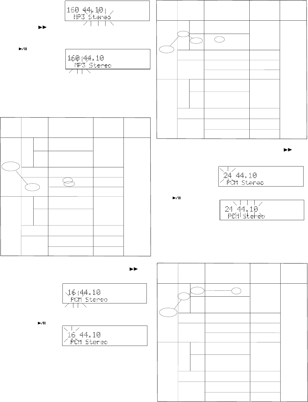
kHz
kHz
kHz
kbps
kHz
kbps
16 bit
PCM
24 bit
16 bit
mp3/bwf
(80, 64, 40, 32, 24, 16)
24, 22.05, 16
mp3/bwf
(160, 128, 80, 64, 40, 32)
48, 44.1, 32
MP3
mpg/bwf
(192, 128, 96, 64, 48, 32)
48, 44.1, 32
MP2
16, 12, 11.025, 8
48, 44.1, 32, 24, 22.05,
wav/bwf
96, 88.2, 48, 44.1
Mono
BWF ext.
wav/bwfmp3/bwf
mp3/bwf
mpg/bwf
(160, 128, 80, 64, 40, 32)
24, 22.05, 16
(320, 256, 160, 128, 80, 64)
48, 44.1, 32
MP3
(384, 256, 192, 128, 96, 64)
48, 44.1, 32
MP2
PCM
Stereo
24 bit
wav/bwf
16, 12, 11.025, 8
48, 44.1, 32, 24, 22.05,
96, 88.2, 48, 44.1
File ext.
Fs kHz and
(Bit rate kbps)
Audio
Format
Channel(s)
16 bit
PCM
24 bit
16 bit
mp3/bwf
(80, 64, 40, 32, 24, 16)
24, 22.05, 16
mp3/bwf
(160, 128, 80, 64, 40, 32)
48, 44.1, 32
MP3
mpg/bwf
(192, 128, 96, 64, 48, 32)
48, 44.1, 32
MP2
16, 12, 11.025, 8
48, 44.1, 32, 24, 22.05,
wav/bwf
96, 88.2, 48, 44.1
Mono
BWF ext.
wav/bwfmp3/bwf
mp3/bwf
mpg/bwf
(160, 128, 80, 64, 40, 32)
24, 22.05, 16
(320, 256, 160, 128, 80, 64)
48, 44.1, 32
MP3
(384, 256, 192, 128, 96, 64)
48, 44.1, 32
MP2
PCM
Stereo
24 bit
wav/bwf
16, 12, 11.025, 8
48, 44.1, 32, 24, 22.05,
96, 88.2, 48, 44.1
File ext.
Fs kHz and
(Bit rate kbps)
Audio
Format
Channel(s)
kHz
kHz
16 bit
PCM
24 bit
16 bit
mp3/bwf
(80, 64, 40, 32, 24, 16)
24, 22.05, 16
mp3/bwf
(160, 128, 80, 64, 40, 32)
48, 44.1, 32
MP3
mpg/bwf
(192, 128, 96, 64, 48, 32)
48, 44.1, 32
MP2
16, 12, 11.025, 8
48, 44.1, 32, 24, 22.05,
wav/bwf
96, 88.2, 48, 44.1
Mono
BWF ext.
wav/bwfmp3/bwf
mp3/bwf
mpg/bwf
(160, 128, 80, 64, 40, 32)
24, 22.05, 16
(320, 256, 160, 128, 80, 64)
48, 44.1, 32
MP3
(384, 256, 192, 128, 96, 64)
48, 44.1, 32
MP2
PCM
Stereo
24 bit
wav/bwf
16, 12, 11.025, 8
48, 44.1, 32, 24, 22.05,
96, 88.2, 48, 44.1
File ext.
Fs kHz and
(Bit rate kbps)
Audio
Format
Channel(s)
- 32 -
5. Press and release the F.FWD/+ button to
tab through MP3, MP2 and PCM. Note that
other changes
occur when the
format
changes.
When correct, press and release the ENTER
button .
The display
switches to the
next
RecFormat menu choice flashing.
Note
In our example, we chose PCM. The chart below reflects the
settings change.
4. Press and
release the
F.FWD/+
button to
toggle between Mono and Stereo. When
correct, press and release the ENTER button
. The
display
switches to
Format flash-
ing.
Note
In the example, the change from Mono to Stereo automati-
cally doubled the bit rate. The change is illustrated in the
chart below.
6. Press and release the F.FWD/+ button to
toggle between 16 bit and 24 bit PCM.
When correct,
press and
release the
ENTER button
.
The display
switches to the
next
RecFormat menu choice flashing.
Note
The chart below reflects the settings change.
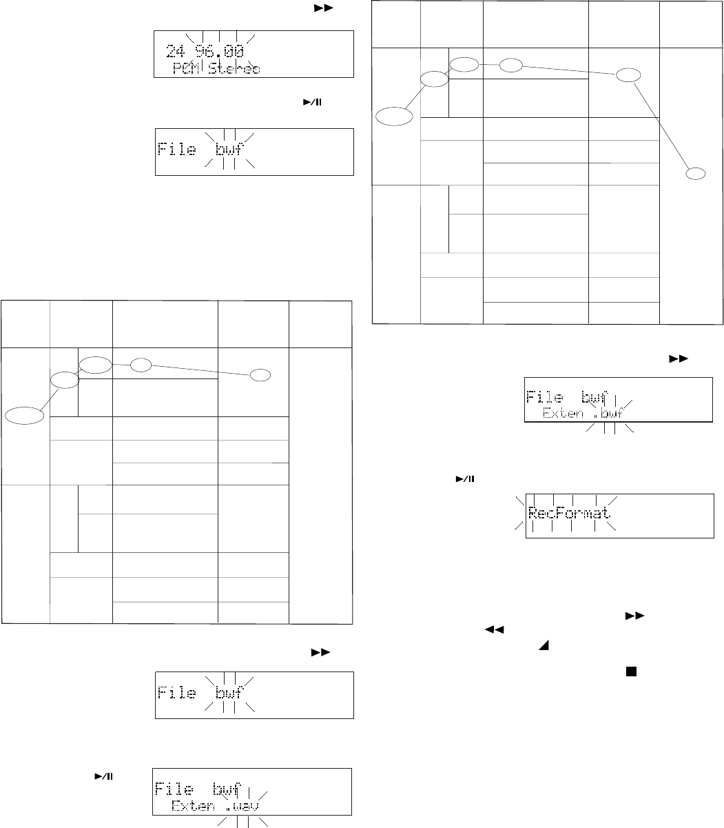
16 bit
PCM
24 bit
16 bit
mp3/bwf
(80, 64, 40, 32, 24, 16)
24, 22.05, 16
mp3/bwf
(160, 128, 80, 64, 40, 32)
48, 44.1, 32
MP3
mpg/bwf
(192, 128, 96, 64, 48, 32)
48, 44.1, 32
MP2
16, 12, 11.025, 8
48, 44.1, 32, 24, 22.05,
wav/bwf
96, 88.2, 48, 44.1
Mono
BWF ext.
wav/bwfmp3/bwf
mp3/bwf
mpg/bwf
(160, 128, 80, 64, 40, 32)
24, 22.05, 16
(320, 256, 160, 128, 80, 64)
48, 44.1, 32
MP3
(384, 256, 192, 128, 96, 64)
48, 44.1, 32
MP2
PCM
Stereo
24 bit
wav/bwf
16, 12, 11.025, 8
48, 44.1, 32, 24, 22.05,
96, 88.2, 48, 44.1
File ext.
Fs kHz and
(Bit rate kbps)
Audio
Format
Channel(s)
7. Press and release the F.FWD/+ button to
tab through the
available bit
rate settings.
When correct,
press and release the ENTER button .
The display
switches to the
next
RecFormat
menu choice flashing.
Notes
In the example there is no choice of sample frequency so the
next RecFormat choice is displayed.
The chart below reflects the settings change.
8. Press and release the F.FWD/+ button to
toggle between
a bwf file and
the other avail-
menu choice flashing.
Notes
In the example bwf was chosen so the wav/bwf RecFormat
choice is displayed.
The chart below reflects this settings change.
able file type.
When correct, press and release the ENTER
button .
The display
switches to the
next RecFormat
- 33 -
9. Press and release the F.FWD/+ button to
toggle between
a .wav and a
.bwf file exten-
sion.
When correct, press and release the ENTER
button .
The display
returns to the
RecFormat
menu choice
flashing.
You can:
• Press and release the F.FWD/+ button or the -/
F.REV button to tab to another menu choice, or
• Press and release the MENU/STORE button to write
the menu changes and return to stop mode, or
• Press and release the CANCEL button to cancel all
menu changes and return to stop mode.
kHz
16 bit
PCM
24 bit
16 bit
mp3/bwf
(80, 64, 40, 32, 24, 16)
24, 22.05, 16
mp3/bwf
(160, 128, 80, 64, 40, 32)
48, 44.1, 32
MP3
mpg/bwf
(192, 128, 96, 64, 48, 32)
48, 44.1, 32
MP2
16, 12, 11.025, 8
48, 44.1, 32, 24, 22.05,
wav/bwf
96, 88.2, 48, 44.1
Mono
BWF ext.
wav/bwfmp3/bwf
mp3/bwf
mpg/bwf
(160, 128, 80, 64, 40, 32)
24, 22.05, 16
(320, 256, 160, 128, 80, 64)
48, 44.1, 32
MP3
(384, 256, 192, 128, 96, 64)
48, 44.1, 32
MP2
PCM
Stereo
24 bit
wav/bwf
16, 12, 11.025, 8
48, 44.1, 32, 24, 22.05,
96, 88.2, 48, 44.1
File ext.
Fs kHz and
(Bit rate kbps)
Audio
Format
Channel(s)
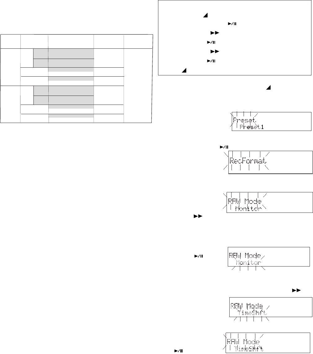
- 34 -
Digi-IN Rec Format
Most of the RecFormat parameters recorded
from a digital input source are determined by the
input source. They are not changed because of
settings made in the RecFormat menu.
The shaded areas in the chart below are set by
the input source and ignore RecFormat menu
settings.
Digi-IN RecFormat chart
3. Press and
release the
F.FWD/+
button
until RAW Mode is displayed.
4. With RAW Mode flashing, press and release
the ENTER
button .
The RAW
Mode menu choice is flashing.
5. Press and release the F.FWD/+ button to
Notes:
• An audio drop out of the monitoring signal may occur
during RAW during high bit rate MP3 recording.
• RAW and 24-bit recording requires high CF card access
speed (see CARD CHECK page 22).
• RAW is not available for 24-bit recording.
• Verify is simultaneously available with RAW or Time
Shift for appropriate files (see charts on page 14).
How to set or change the RAW Mode
Quick instructions
Press & hold MENU/STORE 2 sec ....... Preset
Double Click ENTER .................. RecFormat
Press F.FWD/+ ........................... RAW Mode
Press ENTER .................... Monitor/TimeShft
Press F.FWD/+ ....... toggle Monitor/TimeShft
Press ENTER ............................. RAW Mode
Press MENU/STORE .................... store & exit
1. From stop, press and hold the MENU/
STORE button for about 2 seconds. Preset
will appear (flashing) in the display.
Example
display
2. While Preset is flashing, double click the
ENTER button .
Example
display
A menu choice will be flashing.
toggle between
Monitor and
TimeShft.
and release the
ENTER button
.
RAW Mode
RAW (Read After Write) mode sets the operation
of the MONITOR switch.
RAW is an electronic Read After Write. In all
modes except 24 bit recording, the PMD671 can
read a recording on the CF Card while simulta-
neously recording onto the CF Card.
When RAW Mode is at Monitor and if the MONI-
TOR switch is at FILE when recording begins, the
monitoring signal sent to the PHONES jack and
LINE OUT jacks is read from the CF card a
maximum of 2 seconds after it is recorded. Thus,
the monitored signal is not the source but is the
recording.
When RAW Mode is at TimeShft and if the MONI-
TOR switch is at FILE when recording begins, the
monitoring signal sent to the PHONES jack and
LINE OUT jacks is the same as the source until a
playback button is activated. (PLAY/PAUSE,
TRACK JUMP, F.FWD or F.REV) The recording
before the playback button was activated, and
previously recorded tracks, can then be moni-
tored and reviewed using normal playback con-
trols while recording continues.
6. When the desired state is displayed, press
16 bit
PCM
24 bit
16 bit
PCM
24 bit
mp3/bwf
(160, 128, 80, 64, 40, 32)
48, 44.1
MP3
mpg/bwf
(192, 128, 96, 64, 48, 32)
48, 44.1
MP2
wav/bwf
Mono
wav/bwf
mp3/bwf
(320, 256, 160, 128, 80, 64)
48, 44.1
mpg/bwf
(384, 256, 192, 128, 96, 64)
48, 44.1
wav/bwf
48 , 44.1
96, 88.2, 44, 44.1
MP3
MP2
Stereo
96, 88.2, 44, 44.1
48 , 44.1
BWF ext.File ext.
Fs kHz and
(Bit rate kbps)
Audio
Format
Channel(s)
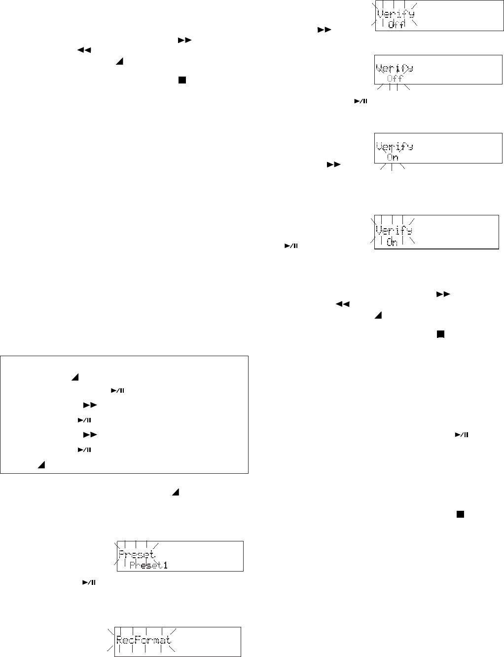
- 35 -
The display returns to RAW Mode flashing.
You can:
• Press and release the F.FWD/+ button or the -/
F.REV button to tab to another menu choice, or
• Press and release the MENU/STORE button to
write the menu changes and return to stop mode, or
• Press and release the CANCEL button to cancel all
menu changes and return to stop mode.
Verify
Verify is an automatic, electronic, Read After
Write check. With Verify On, the PMD671 con-
tinually reads the CF card about one second
after the recording. It compares what is recorded
to the source signal. A mismatch results in an
error message.
Verify does not depend on the position of the
MONITOR switch.
Verify does not function during MP2 record-
ing.
See charts on page 14.
How to set or change Verify
Quick instructions
Press & hold MENU/STORE 2 sec ....... Preset
Double Click ENTER .................. RecFormat
Press F.FWD/+ until ............................ Verify
Press ENTER .....................................Off/On
Press F.FWD/+ ........................ toggle Off/On
Press ENTER ...................................... Verify
Press MENU/STORE .................... store & exit
1. From stop, press and hold the MENU/
STORE button for about 2 seconds. Preset
will appear (flashing) in the display.
2. While Preset is
flashing, double
click the EN-
TER button .
Example display
A menu choice will be flashing.
4. With Verify flash-
ing, press and
release the
3. Press and release
the F.FWD/+
button until
ENTER button .
Verify menu choice is flashing.
5. Press and re-
lease the F.FWD/
+ button to
toggle between On and Off.
6. When the desired state is displayed, press
and release the
ENTER button
.
The display returns to Verify flashing.
You can:
• Press and release the F.FWD/+ button or the -/
F.REV button to tab to another menu choice, or
• Press and release the MENU/STORE button to
write the menu changes and return to stop mode, or
• Press and release the CANCEL button to cancel all
menu changes and return to stop mode.
PupPreRec
Power Up Pre Record buffers (remembers) audio
during REC PAUSE. When you slide the REC
switch to engage record, CONT? is displayed.
• Press and release the PLAY button to
record the buffered audio and continue
recording.
• Slide and release the REC switch again to
discard the buffered audio and continue
recording from that point.
• Press and release the STOP button to
discard the buffered audio and stop record-
ing.
Note:
If there is less than 5 minutes of REC REMAIN time
PupPreRec does not work.
Verify is displayed.
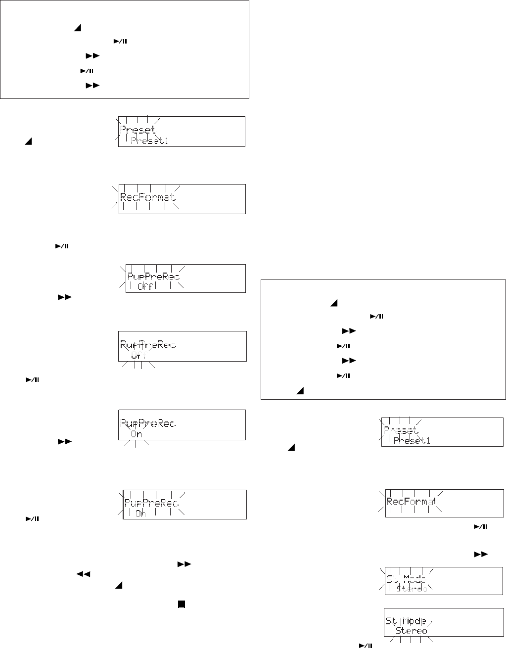
How to set or change PupPreRec
Quick instructions
Press & hold MENU/STORE 2 sec ....... Preset
Double Click ENTER .................. RecFormat
Press F.FWD/+ until ................... PupPreRec
Press ENTER .....................................Off/On
Press F.FWD/+ ........................ toggle Off/On
Example display
3. Press and release
the F.FWD/+
button until
PupPreRec is displayed.
4. With PupPreRec
flashing, press
and release the
ENTER button
.
PupPreRec menu choice is flashing.
5. Press and release
the F.FWD/+
button to
toggle between On and Off.
6. When the desired state is displayed, press
and release the
ENTER button
.
The display returns to PupPreRec flashing.
You can:
• Press and release the F.FWD/+ button or the -/
F.REV button to tab to another menu choice, or
• Press and release the MENU/STORE button to write
the menu changes and return to stop mode, or
• Press and release the CANCEL button to cancel all
menu changes and return to stop mode.
St Mode
Stereo Mode determines which input channels
are recorded onto the Left and Right channels.
There are three Stereo Modes:
Stereo - The Left input channel is recorded onto
the Left channel, and the Right input channel is
recorded onto the Right channel.
L-Stereo - The Left input channel is recorded
onto the Left channel, and onto the Right channel.
0-20dB - For secure recording, the Left channel is
recorded at the normal record level and the Right
channel is reduced by 20dB.
Notes:
• If the input is set to INT MIC and St Mode is set to 0-
20dB, the St Mode of the recording is automatically
switched to L-Stereo.
• If a mono source input (INT MIC or L channel only) the
mono input is also recorded on the R channel reduced
by 20dB.
1. From stop, press
and hold the
MENU/STORE
button for about 2
seconds.
2. With Preset
flashing in the
display, double click the ENTER button .
3. Press and release the F.FWD/+ button
until St Mode is
displayed.
4. With St Mode
flashing, press
and release the
ENTER button .
St Mode menu choice is flashing.
How to set or change St Mode
Quick instructions
Press & hold MENU/STORE 2 sec ....... Preset
Double Click ENTER .................. RecFormat
Press F.FWD/+ until ........................ St Mode
Press ENTER ......... Stereo/L-Stereo/0-20dB
Press F.FWD/+ ..................... tab thru modes
Press ENTER .................................. St Mode
Press MENU/STORE .................... store & exit
1. From stop, press
and hold the
MENU/STORE
button for about 2
seconds.
2. With Preset
flashing in the
display, double
click the ENTER
button .
- 36 -
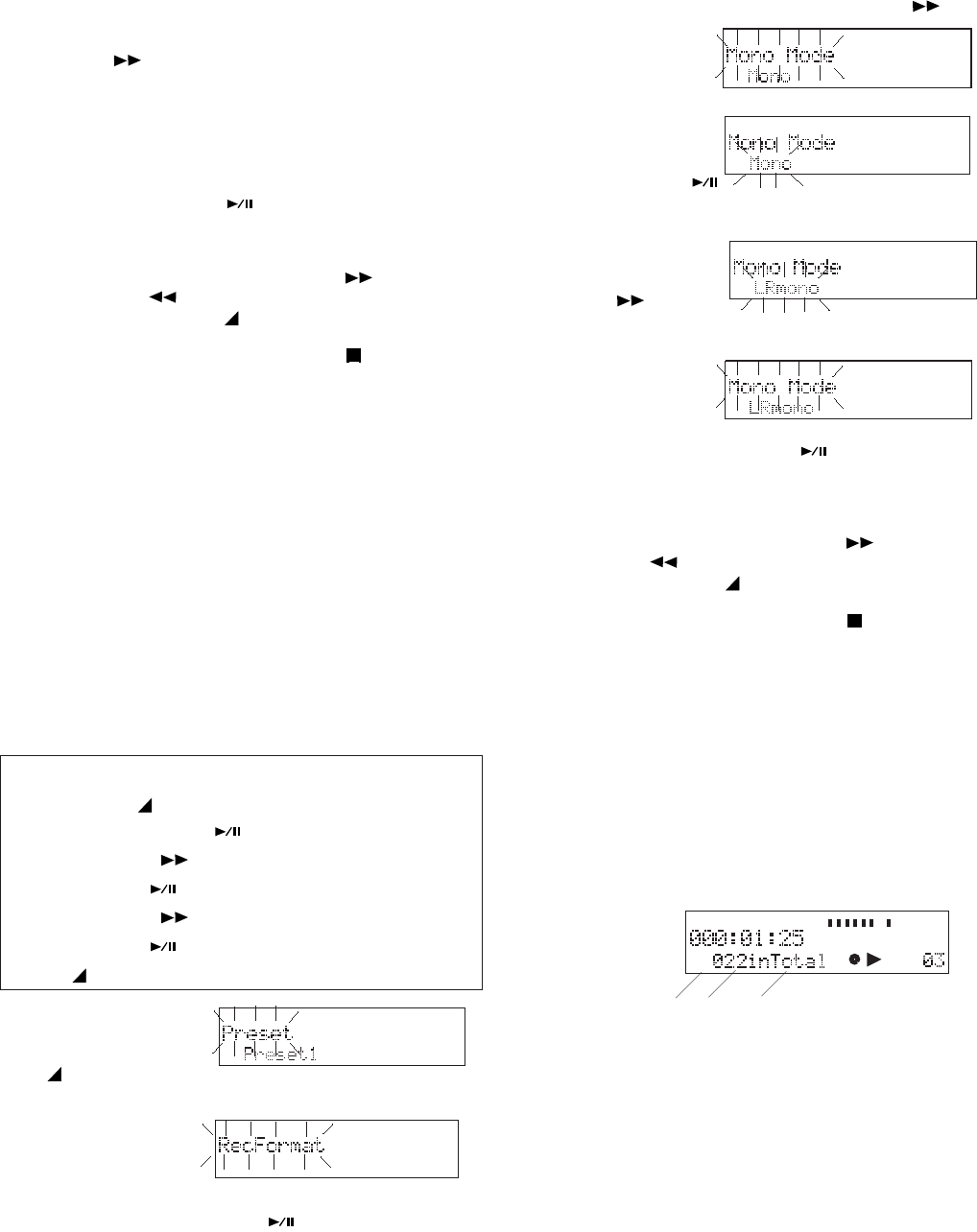
- 37 -
5. Press and release
the F.FWD/+
button to tab
1. From stop, press
and hold the
MENU/STORE
button for about 2 seconds.
2. With Preset
flashing in the
display double
click the ENTER button .
until Mono Mode
is displayed.
4. With Mono Mode
flashing Press
and release the
5. Press and release
the F.FWD/+
button to
toggle between Mono and LRMono.
6. When the desired
mode is dis-
played, press and
release the ENTER button .
The display returns to Mono Mode flashing.
You can:
• Press and release the F.FWD/+ button or the -/
F.REV button to tab to another menu choice, or
• Press and release the MENU/STORE button to write
the menu changes and return to stop mode, or
• Press and release the CANCEL button to cancel all
menu changes and return to stop mode.
Auto Mark
Auto Mark turns the automatic EDL mark feature
on or off.
On - During record after a REC PAUSE, an EDL
mark is added to the track.
As recording is resumed and the EDL mark is
added, the following appear for a few seconds.
a b c
MARK (a) is displayed to indicate that the number
(b) is the EDL mark number. "In Total" (c) reminds
you that EDL marks are counted from the begin-
ning of the CF card, not the beginning of the
current track.
Off - Pause during record does not add an EDL
mark to the track.
Example
display
MARK
TIMETRACK
-dB
00 40 20 12 6 2 0 over
-dB
R
L
ENTER button .
Mono Mode menu choice flashing.
through Stereo, L-Stereo and 0-20db.
6. When the desired
mode is displayed,
press and release
the ENTER button .
The display returns to St Mode flashing.
You can:
• Press and release the F.FWD/+ button or the -/
F.REV button to tab to another menu choice, or
• Press and release the MENU/STORE button to write
the menu changes and return to stop mode, or
• Press and release the CANCEL button to cancel all
menu changes and return to stop mode.
Mono Mode
Mono Mode determines which input channel(s)
are recorded as the mono channel.
There are two Mono Modes:
Mono - The Left input channel is recorded as the
mono channel.
LR Mono - The Left input channel and the Right
input channel are mixed (combined) and recorded
[(L+R)/2] as the mono channel.
How to set or change Mono Mode
Quick instructions
Press & hold MENU/STORE 2 sec ....... Preset
Double Click ENTER .................. RecFormat
Press F.FWD/+ until .................. Mono Mode
Press ENTER ........................Mono/LRmono
Press F.FWD/+ ..................... tab thru modes
Press ENTER ............................ Mono Mode
Press MENU/STORE .................... store & exit
3. Press and release the F.FWD/+ button
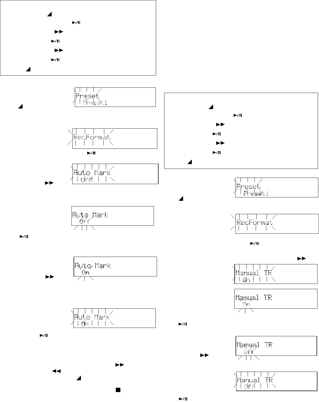
- 38 -
How to set or change Auto Mark
Quick instructions
Press & hold MENU/STORE 2 sec ....... Preset
Double Click ENTER .................. RecFormat
Press F.FWD/+ until ..................... Auto Mark
Press ENTER .....................................Off/On
Press F.FWD/+ ........................ toggle Off/On
Press ENTER ............................... Auto Mark
Press MENU/STORE .................... store & exit
button for about 2 seconds.
2. With Preset
flashing in the
display double
click the ENTER button .
3. Press and re-
lease the F.FWD/
+ button until
4. With Auto Mark
flashing. press
and release the
ENTER button
.
5. Press and re-
lease the F.FWD/
+ button to
toggle between
On and Off.
6. When correct,
press and re-
lease the ENTER
button .
Auto Mark is displayed.
Auto Mark menu choice is flashing.
The display returns to Auto Mark flashing.
You can:
• Press and release the F.FWD/+ button or the -/
F.REV button to tab to another menu choice, or
• Press and release the MENU/STORE button to
write the menu changes and return to stop mode, or
• Press and release the CANCEL button to cancel all
menu changes and return to stop mode.
1. From stop, press
and hold the
MENU/STORE
button for about 2 seconds.
2. With Preset
flashing in the
display, double
click the ENTER button .
3. Press and release the F.FWD/+ button
until Manual TR is
displayed.
. Manual TR menu choice is flashing.
How to set or change Manual TR
Quick instructions
Press & hold MENU/STORE 2 sec ....... Preset
Double Click ENTER .................. RecFormat
Press F.FWD/+ until .................... Manual TR
Press ENTER .....................................Off/On
Press F.FWD/+ ........................ toggle Off/On
Press ENTER ..............................Manual TR
Press MENU/STORE .................... store & exit
5. Press and release
the F.FWD/+
button to
toggle between On and Off.
4. With Manual TR
flashing, press
and release the
ENTER button
1. From stop, press
and hold the
MENU/STORE
Manual TR
When Manual track incrementing is on, slide and
release the REC switch during recording to
increment the track. A new track is created at that
point. There is no break in recording. When
Manual track incrementing is off, sliding and
releasing REC switch during recording does
nothing.
Default setting is On.
6. When correct,
press and release
the ENTER button
.
The display returns to Manual TR flashing.
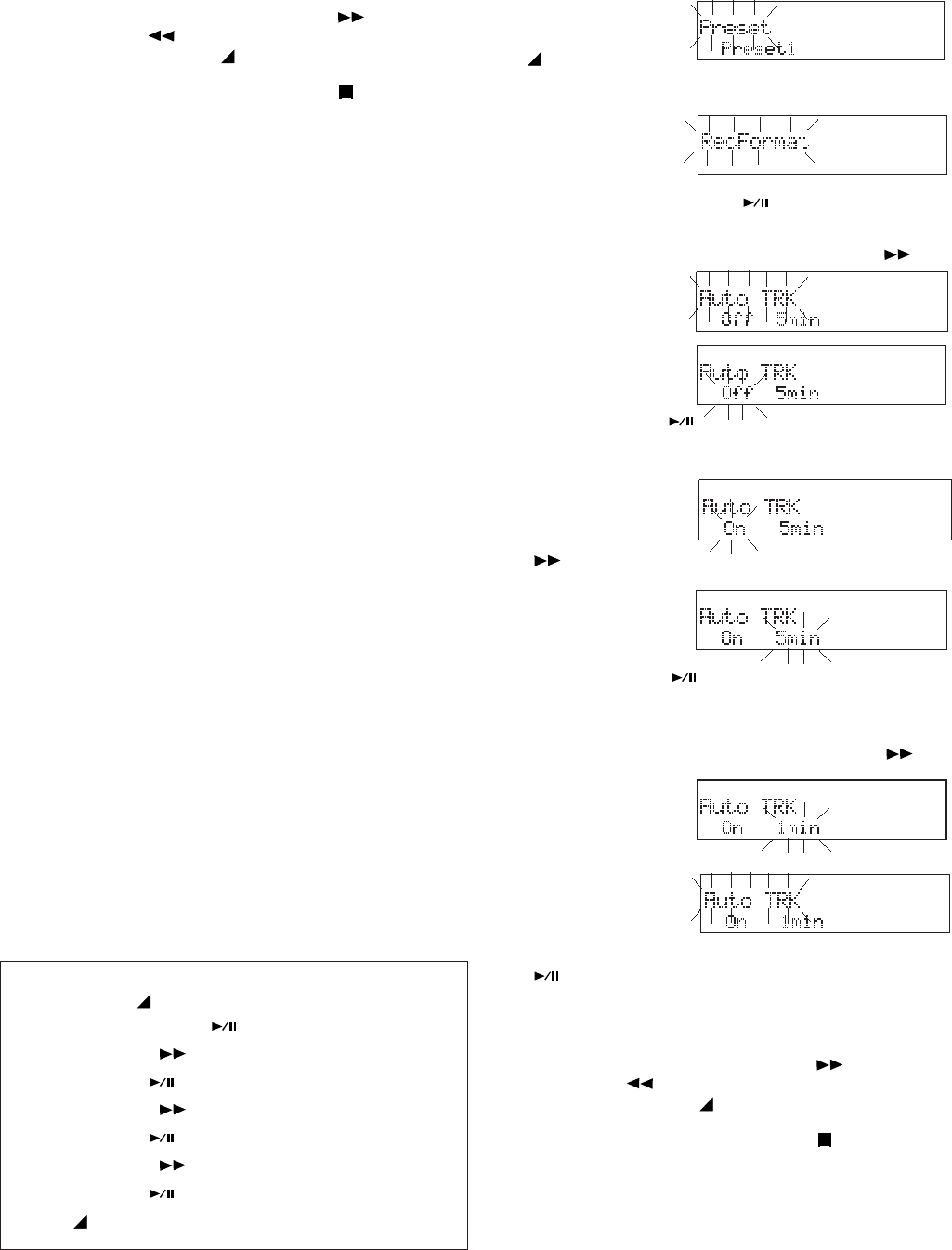
- 39 -
1. From stop, press
and hold the
MENU/STORE
button for about 2 seconds.
2. With Preset
flashing in the
display, double
click the ENTER button .
3. Press and release the F.FWD/+ button
until Auto TRK is
displayed.
4. With Auto TRK
flashing, press
and release the
You can:
• Press and release the F.FWD/+ button or the -/
F.REV button to tab to another menu choice, or
• Press and release the MENU/STORE button to write
the menu changes and return to stop mode, or
• Press and release the CANCEL button to cancel all
menu changes and return to stop mode.
Auto TRK
During recording, Auto Track Incrementing breaks
the recording into multiple tracks of a preset
length of time. At the preset time, the next track
number is begun without stopping recording.
Timed tracks are helpful when recording long
sessions such as meetings, speeches, surveil-
lance sessions, or recordings for transcription.
During playback, timed tracks make finding a
particular passage easy because of the relation-
ship between track numbers and time.
Auto Track Incrementing can be On or Off. If On,
the time interval can be set to: 1, 5, 10, 15 or 30
minutes; or 1, 2, 6, 8, 12 or 24 hours.
For example, if Minute Track is recorded (a new
track every minute) you can select track 3 to play
approximately the 3rd minute of recording. To go
directly to the beginning of the 10th minute, select
track 10, etc.
The table below shows the relationship between
time and tracks in Minute Track.
Track Recording time
# minutes:seconds
1 ............................... 0:00 - 0:59
2 ................................ 1:00-1:59
3 ................................ 2:00-2:59
.
.
..
80 ............................. 79:00-79:56
..
How to set or change Auto TRK
Quick instructions
Press & hold MENU/STORE 2 sec ....... Preset
Double Click ENTER .................. RecFormat
Press F.FWD/+ until ...................... Auto TRK
Press ENTER .....................................Off/On
Press F.FWD/+ ........................ toggle Off/On
Press ENTER .................................. duration
Press F.FWD/+ .......................... tab duration
Press ENTER ................................Auto TRK
Press MENU/STORE .................... store & exit
ENTER button .
On/Off menu choice is flashing.
5. Press and
release the
F.FWD/+ button
to toggle between On and Off.
6. When correct,
press and
release the
ENTER button . Duration choice is flash-
ing.
7. Press and release the F.FWD/+ button to
tab through the
duration
choices.
8. When correct,
press and
release the
ENTER button
.
The display returns to Auto TRK flashing.
You can:
• Press and release the F.FWD/+ button or the -/
F.REV button to tab to another menu choice, or
• Press and release the MENU/STORE button to write
the menu changes and return to stop mode, or
• Press and release the CANCEL button to cancel all
menu changes and return to stop mode.
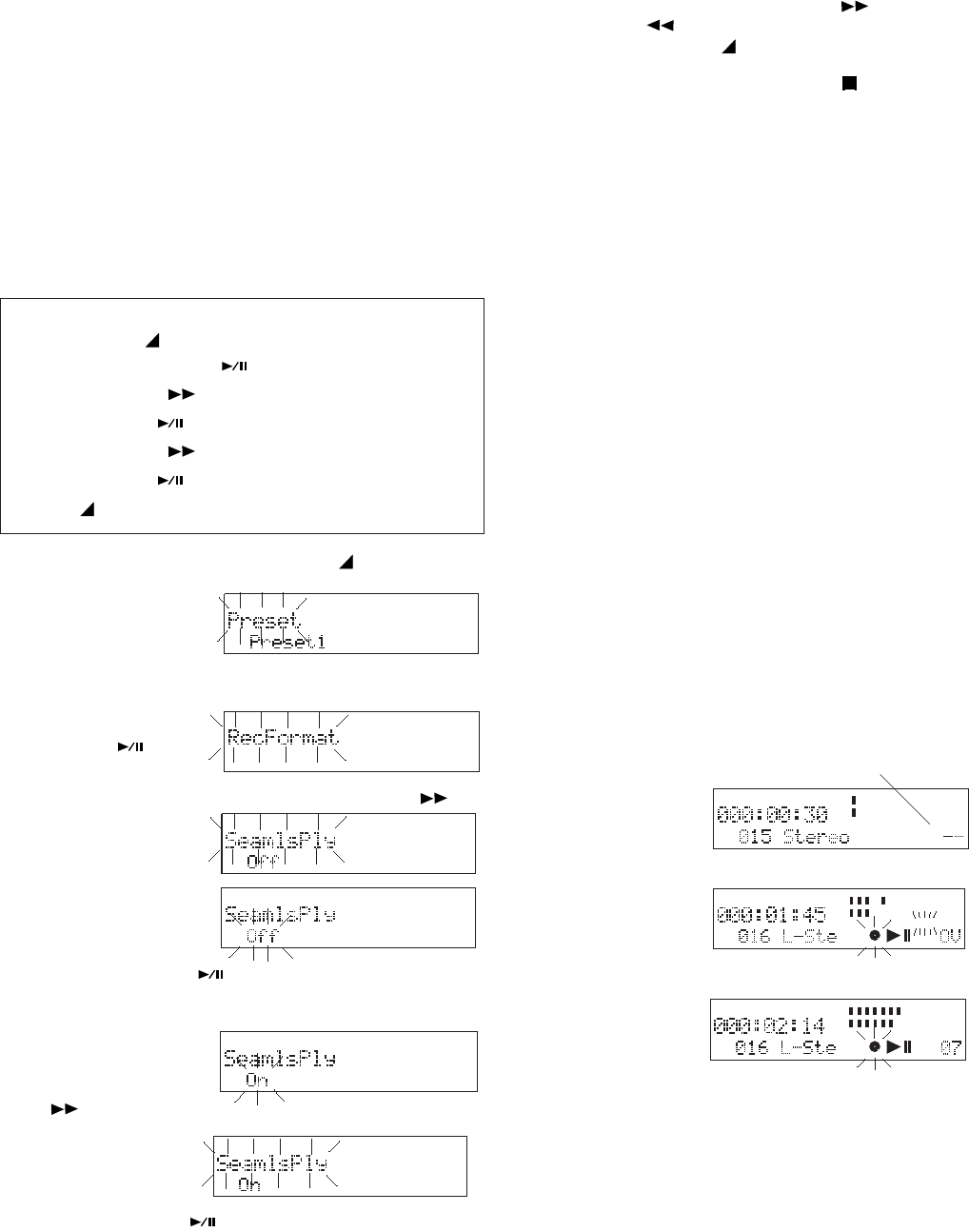
- 40 -
STORE button
for about 2
seconds.
2. With Preset flashing in the display, double
click the ENTER
button .
3. Press and release the F.FWD/+ button
until SeamlsPly
is displayed.
4. With SeamlsPly
flashing, press
and release the
ENTER button .
On/Off menu choice is flashing.
5. Press and
release the
F.FWD/+ button
to toggle between On and Off
6. When correct,
press and
release the
ENTER button .
The display returns to SeamlsPly flashing.
Seamless Play.
When Seamless Play is On during playback,
multiple tracks will be played back in sequence
without any break (space) between the tracks.
When Seamless Play is Off during playback,
multiple tracks will be played back in sequence
with breaks (brief periods of silence) between the
tracks.
Default setting is Off.
How to set or change SeamlsPly
Quick instructions
Press & hold MENU/STORE 2 sec ....... Preset
Double Click ENTER .................. RecFormat
Press F.FWD/+ until .................... SeamlsPly
Press ENTER .....................................Off/On
Press F.FWD/+ ........................ toggle Off/On
Press ENTER .............................. SeamlsPly
Press MENU/STORE .................... store & exit
1. From stop, press and hold the MENU/
You can:
• Press and release the F.FWD/+ button or the -/
F.REV button to tab to another menu choice, or
• Press and release the MENU/STORE button to write
the menu changes and return to stop mode, or
• Press and release the CANCEL button to cancel all
menu changes and return to stop mode.
Silent Skip.
When set to On, Silent skip automatically pauses
recording when there is a period of silence and
continues recording when sound resumes. Silent
Skip looks for sound below a preset level for a
preset period of time. When that occurs, the
PMD671 switches to record pause. When a
signal exceeding the dB level you set is input,
recording resumes. If set to TR, a new track is
started when recording resumes.
You can set the preset time for 01, 02, 03, 04 or
05 seconds.
You can set the decibel level (dB) to- 20, -25, -30,
-35, -40, -45, -50, -55 or -60 dB.
For example, if you are both the recorder and
master of ceremonies for an event, you can
preset the PMD671 for recording and automati-
cally start recording when you start speaking into
the microphone.
When the Auto Mark feature is at On, resumption
of recording after a record pause by Silent Skip
adds an EDL mark.
The S.SKIP icon
appears in the
display while Silent
Skip is On.
S.SKIP
TRACK
TRACK TIME
-dB
00 40 20 12 62 0 over
-dB
R
L
S.SKIP
The S.SKIP icon is
flashing during a
MIC
INT S.SKIP
TRACK
TRACK TIME
-dB
00 40 20 12 62 0over
-dB
R
L
Silent Skip record pause.
Manual overrides:
MIC
INT S.SKIP
TRACK
TRACK TIME
-dB
00 40 20 12 6 2 0 over
-dB
R
L
Pause During
recording press and
release the REC PAUSE button to force a record-
ing pause. S.SKIP icon is steady. Slide the REC
Button to resume recording.
Resume During Silent Skip pause, slide the REC
Button to resume recording. Silent Skip remains
active.
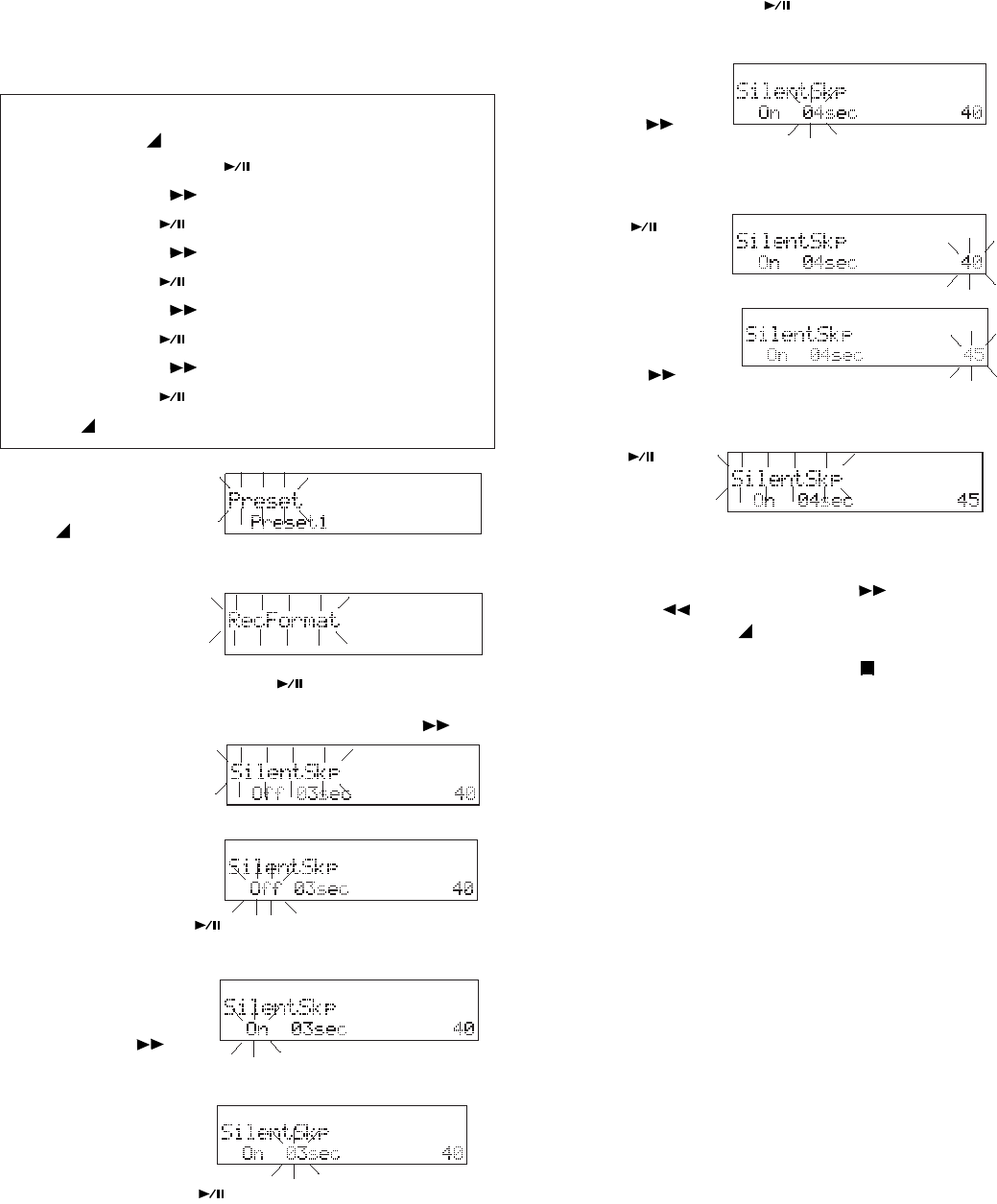
-dB
-dB
-dB
-dB
-dB
-dB
-dB
-dB
- 41 -
How to set or change SilentSkp continued
Default settings are Off, 03 seconds and -40 dB.
How to set or change SilentSkp
Quick instructions
Press & hold MENU/STORE 2 sec ....... Preset
Double Click ENTER .................. RecFormat
Press F.FWD/+ until ...................... SilentSkp
Press ENTER ............................... Off/On/TR
Press F.FWD/+ ....................... tab Off/On/TR
Press ENTER .................................. seconds
Press F.FWD/+ .......................... tab seconds
Press ENTER .................................. decibels
Press F.FWD/+ .......................... tab decibels
Press ENTER ................................ SilentSkp
Press MENU/STORE .................... store & exit
button for about 2 seconds.
2. With Preset
flashing in the
display, double
click the ENTER button .
3. Press and release the F.FWD/+ button
until SilentSkp is
displayed.
4. With SilentSkp
flashing, press
and release the
ENTER button .
On/Off/TR menu choice is flashing.
5. Press and re-
lease the F.FWD/
+ button to
tab between On, Off and TR.
6. When correct,
press and
release the
ENTER button . Seconds choice is flash-
ing.
7. Press and re-
lease the F.FWD/
+ button to
tab through seconds.
8. When correct, press and release the ENTER
button .
Decibel choice
flashing.
9. Press and re-
lease the F.FWD/
+ button to
SilentSkp flashing.
You can:
• Press and release the F.FWD/+ button or the -/
F.REV button to tab to another menu choice, or
• Press and release the MENU/STORE button to
write the menu changes and return to stop mode, or
• Press and release the CANCEL button to cancel all
menu changes and return to stop mode.
tab through decibel choices.
button .
The display
returns to
10. When correct, press and release the ENTER
1. From stop, press
and hold the
MENU/STORE
Auto Cue
Auto Cue skips the silence at the beginning of an
audio track and pauses playback at the point
where the audio begins (sound is loud enough for
long enough). You can adjust how loud (dB's) and
how long (milliseconds) the audio has to be
before playback is cued.
If Single Play is selected, Auto Cue pauses
playback and cues to the sound of the next track
when the end of the track is reached.
The Auto Cue Menu settings permit:
• turning Auto Cue On or Off.
• adjusting the millisecond period in 5 millisec-
ond intervals from 5 to 95 milliseconds.
• adjusting the margin sound level that defines
where audio begins in -5 dB increments from
-20 to -60 dB.
Note
If you don't want to change the seconds or dB settings press
and release the ENTER button several times to tab to
SilentSkp flashing.
Default settings are Off, 20 milliseconds, and -40
dB.
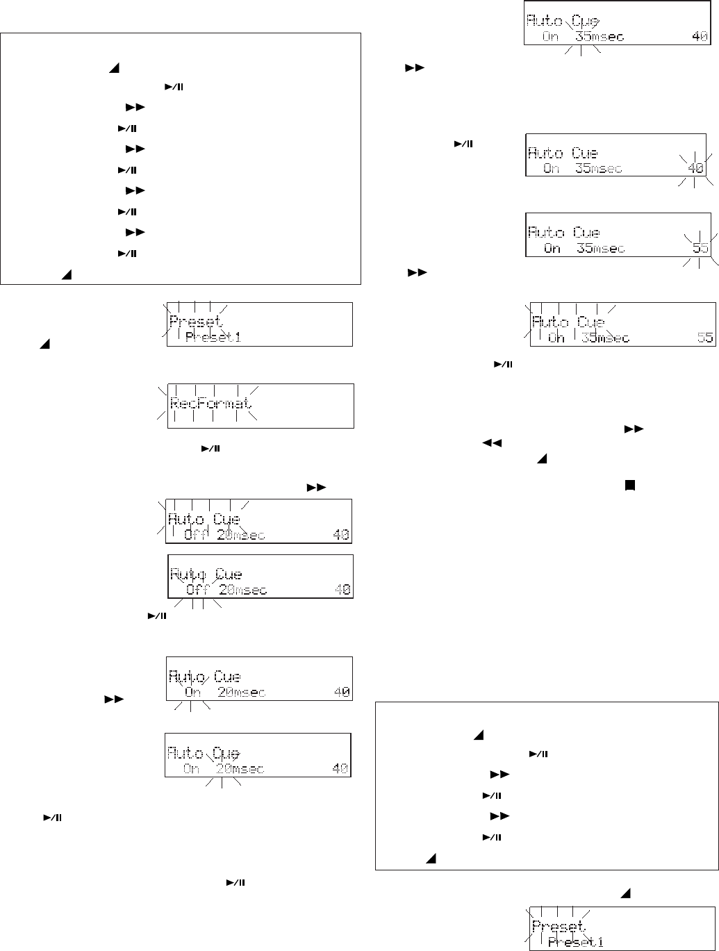
- 42 -
-dB
-dB
-dB
-dB
-dB
-dB
-dB
-dB
STORE button for about 2 seconds.
2. With Preset
flashing in the
display, double
click the ENTER button .
3. Press and release the F.FWD/+ button
until Auto Cue is
displayed.
4. With Auto Cue
flashing, press
and release the
ENTER button .
On/Off menu choice is flashing.
5. Press and re-
lease the F.FWD/
+ button to
toggle between On and Off.
How to set or change Auto Cue
Quick instructions
Press & hold MENU/STORE 2 sec ....... Preset
Double Click ENTER .................. RecFormat
Press F.FWD/+ until ...................... Auto Cue
Press ENTER .....................................Off/On
Press F.FWD/+ ........................ toggle Off/On
Press ENTER ............................milliseconds
Press F.FWD/+ ....................tab milliseconds
Press ENTER .................................. decibels
Press F.FWD/+ .......................... tab decibels
Press ENTER ................................ Auto Cue
Press MENU/STORE .................... store & exit
6. When correct,
press and
release the
ENTER button
. Milliseconds choice flashing.
Note
If you don't want to change the Milliseconds or dB settings
press and release the ENTER button several times to
tab to Auto Cue flashing.
7. Press and
release the
F.FWD/+ button
to tab
through milliseconds.
8. When correct, press and release the ENTER
button .
Decibel choice
flashing.
9. Press and
release the
F.FWD/+ button
The display returns to Auto Cue flashing.
You can:
• Press and release the F.FWD/+ button or the -/
F.REV button to tab to another menu choice, or
• Press and release the MENU/STORE button to write
the menu changes and return to stop mode, or
• Press and release the CANCEL button to cancel all
menu changes and return to stop mode.
S.Monitor
Stop Monitor lets you monitor the source signal
when in stop as well as during record. The
source signal is available at the PHONES jack
or Internal Speaker.
Default setting is Off.
How to set or change S.Monitor
to tab through decibel choices.
10. When correct,
press and re-
lease the EN-
TER button .
1. From stop, press and hold the MENU/
STORE button
for about 2
seconds.
Quick instructions
Press & hold MENU/STORE 2 sec ....... Preset
Double Click ENTER .................. RecFormat
Press F.FWD/+ until ...................... S.Monitor
Press ENTER .....................................Off/On
Press F.FWD/+ ........................ toggle Off/On
Press ENTER ................................ S.Monitor
Press MENU/STORE .................... store & exit
1. From stop, press
and hold the
MENU/
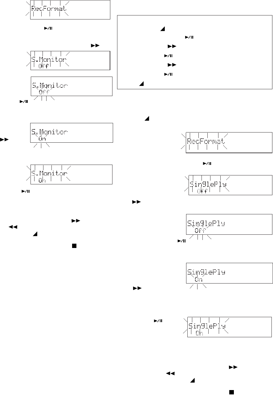
- 43 -
2. With Preset
flashing, in the
display, double
1. From stop,
press and hold
the MENU/
STORE button for about 2 seconds.
2. With Preset
flashing in the
display, double
click the ENTER button .
3. Press and
release the
F.FWD/+ button
4. With SinglePly
flashing, press
and release the
5. Press and
release the
F.FWD/+ button
to toggle
between On and Off.
6. When correct, press and release the ENTER
SinglePly flashing.
You can:
• Press and release the F.FWD/+ button or the -/
F.REV button to tab to another menu choice, or
• Press and release the MENU/STORE button to write
the menu changes and return to stop mode, or
• Press and release the CANCEL button to cancel all
menu changes and return to stop mode.
until SinglePly is displayed.
ENTER button .
On/Off menu choice flashing.
button .
The display
returns to
toggle between On and Off.
6. When correct,
press and
release the
ENTER button .
The display returns to S.Monitor flashing.
You can:
• Press and release the F.FWD/+ button or the -/
F.REV button to tab to another menu choice, or
• Press and release the MENU/STORE button to
write the menu changes and return to stop mode, or
• Press and release the CANCEL button to cancel all
menu changes and return to stop mode.
SinglePly
Off - During playback, when Single Play and
Auto Cue are Off and the end of a track is
reached, the next track automatically starts
playing.
On - During playback, when Single Play is On
and the end of a track is reached, the PMD671
automatically pauses. If Auto Cue is also On in
play cues to start of audio.
Default setting is Off.
How to set or change SinglePly
Quick instructions
Press & hold MENU/STORE 2 sec ....... Preset
Double Click ENTER .................. RecFormat
Press F.FWD/+ until ...................... SinglePly
Press ENTER .....................................Off/On
Press F.FWD/+ ........................ toggle Off/On
Press ENTER ................................ SinglePly
Press MENU/STORE .................... store & exit
click the ENTER button .
3. Press and release the F.FWD/+ button
until S.Monitor is
displayed.
4. With S.Monitor
flashing, press
and release the
ENTER button .
On/Off menu choice is flashing.
5. Press and re-
lease the F.FWD/
+ button to
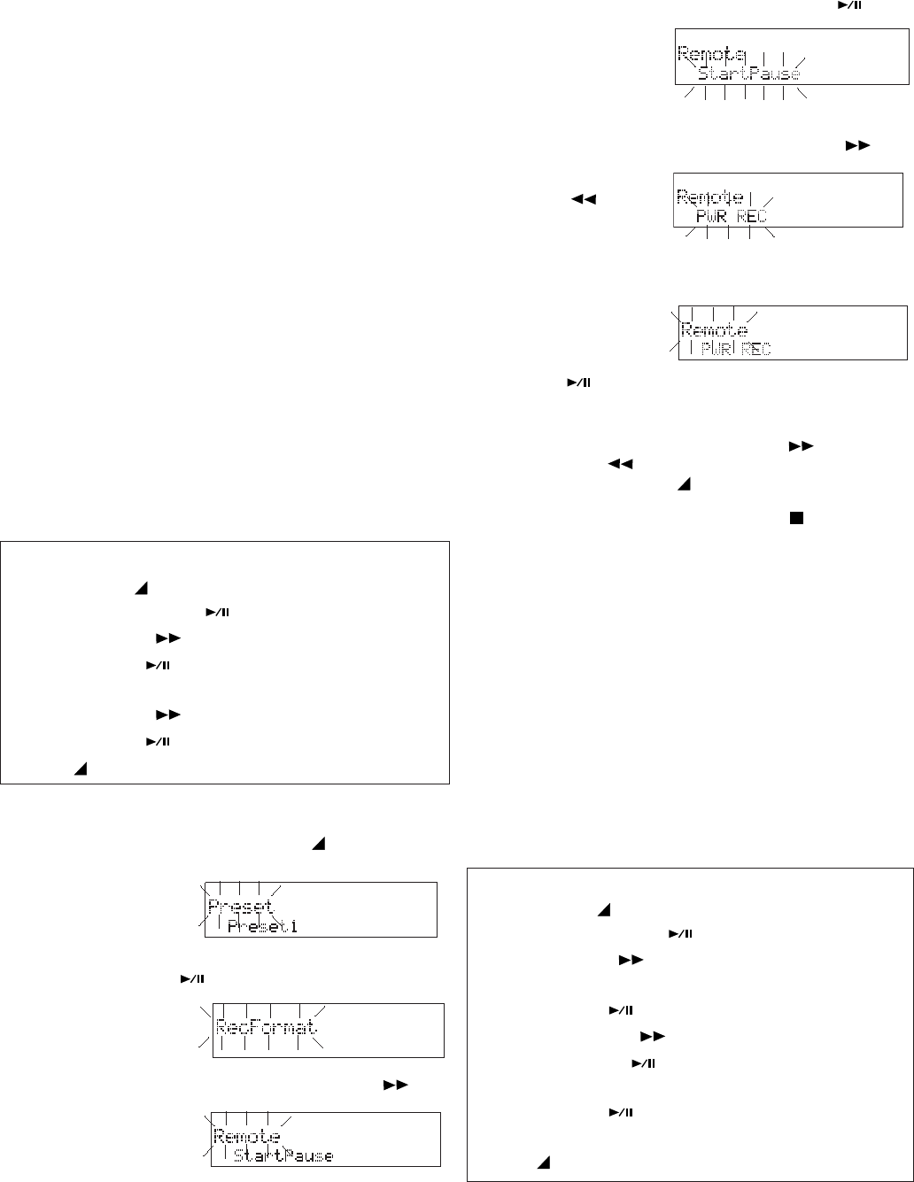
- 44 -
Remote Mode (REMOTE1 jack only)
Use a wired remote (not supplied) to control the
PMD671. There are five remote modes:
• StartPause – during recording or playback,
switch off to pause and on to resume (record-
ing on the same track).
• StrtStp TR - during recording, switch off to
pause recording and on to start recording a
new track.
• EDL Mark – during recording, switch remote
to on to add an EDL mark.
• PWR REC – during power off, switch remote
on to turn power on and begin recording.
During recording, switch remote off to stop
recording and power off.
• Manual TRK – during recording, switch
remote on to increment the track. Recording
continues with a new track created at that
point.
Default is StartPause.
How to set or change the Remote Mode
Quick instructions
Press & hold MENU/STORE 2 sec ....... Preset
Double Click ENTER .................. RecFormat
Press F.FWD/+ until .........................Remote
Press ENTER ...........StartPause/StrtStp TR/
............... EDL Mark/PWR REC/Manual TRK
Press F.FWD/+ ............... tab Remote Modes
Press ENTER ...................................Remote
Press MENU/STORE .................... store & exit
repeatedly until
Remote is dis-
played and
flashing.
accept the
Remote choice
and switch to
RemoteMode choices.
4. Press and release the F.FWD/+ button or
the -/F.REV
button to tab
through the
RemoteMode choices: StartPause, StartStp
TR, EDL Mark, PWR REC, or Manual TRK.
5. When correct,
press and release
the ENTER
button to switch to RemoteMode flashing.
You can:
• Press and release the F.FWD/+ button or the -/
F.REV button to tab to another menu choice, or
• Press and release the MENU/STORE button to write
the menu changes and return to stop mode, or
• Press and release the CANCEL button to cancel all
menu changes and return to stop mode.
Broadcast Wave ID numbers
Broadcast Wave Format (.bwf) has three identifi-
cation numbers in the header (Extension Chunk):
Description, Originator, and Originator Reference.
For example, if the IDs are used for a broadcast
station ID1 could be the identifier of the station,
ID2 could be used for the department code, and
ID3 for the badge number of the reporter.
Default is all ID numbers at 000000.
How to set or change ID numbers
Quick instructions
Press & hold MENU/STORE 2 sec ....... Preset
Double Click ENTER .................. RecFormat
Press F.FWD/+ until ..................... ID1Dscrpt
.................................ID2Origin or ID3OrgRef
Press ENTER ..................... 1st digit flashing
a Press F.FWD/+ .............................. tab 0-9
b Press ENTER ................. save & next digit
Repeat a, b until ................................ 6th digit set
Press ENTER ............................... ID1Dscrpt
.................................ID2Origin or ID3OrgRef
Press MENU/STORE .................... store & exit
1. Select the RemoteMode menu choice:
a. From stop, press and hold the MENU
button for about 2 seconds. Preset will appear
b. While Preset is flashing, double click the
ENTER button .
The last Menu
choice selected
will appear.
2. Press and release the F.FWD/+ button
3. Press and release the ENTER button to
(flashing) in the
display.
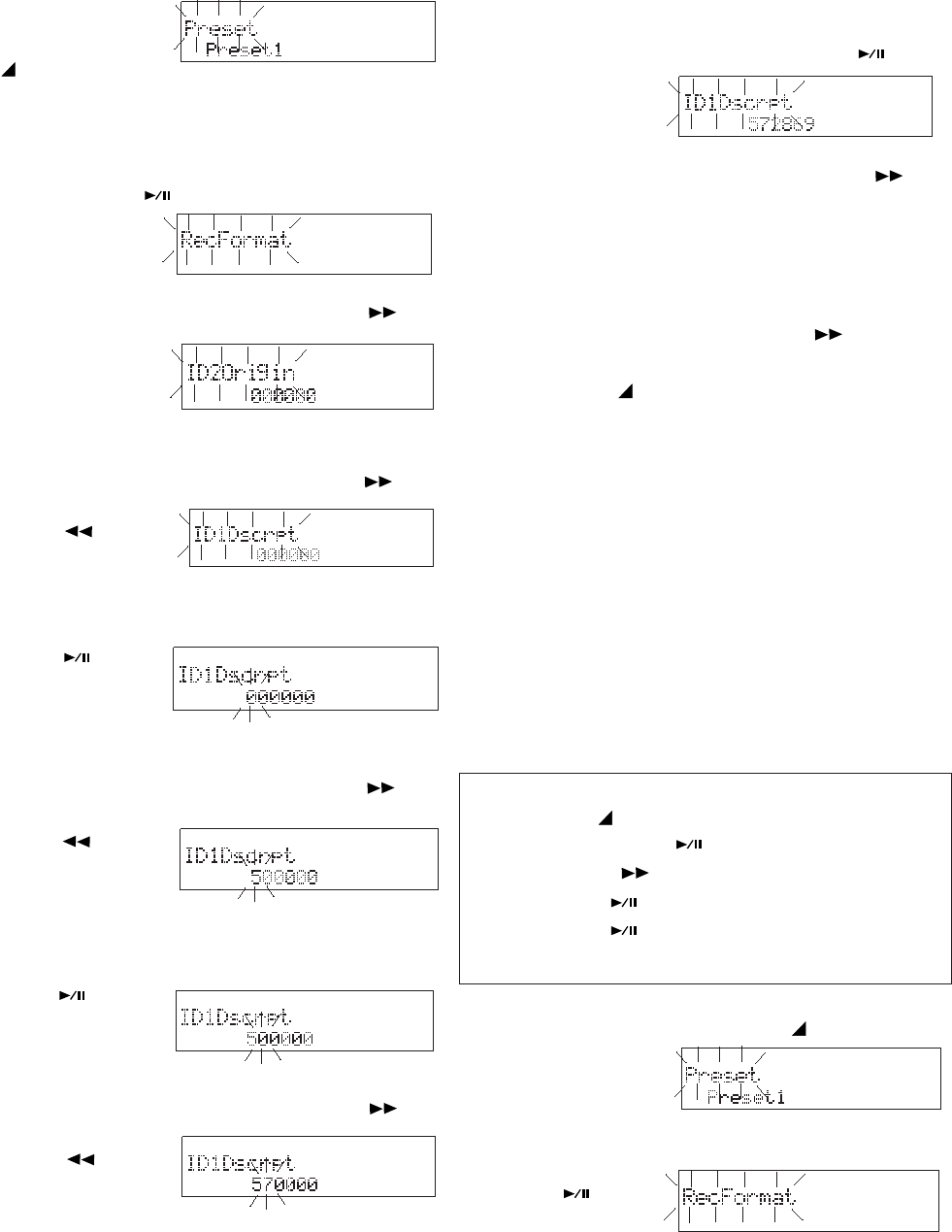
- 45 -
1. Select the ID1 menu choice:
Menu Default
The Default menu choice resets all Menu items to
their defaults. This is convenient if you are setting
up a new configuration because you don't have to
check all the settings, you know they are at the
default.
Defaults are listed for each menu item.
Note:
US defaults are used for illustration. See page 59 for a table
of menu defaults.
Quick instructions
Press & hold MENU/STORE 2 sec ....... Preset
Double Click ENTER .................. RecFormat
Press F.FWD/+ until .......................... Default
Press ENTER .................................. Execute
Press ENTER .......................... EXECUTING
............................................................... exits
the -/F.REV
button to
tab through the
ID choices.
When correct press and release the ENTER
button to
accept the ID#
choice and
switch to the highest number position.
4. Press and release the F.FWD/+ button or
the -/F.REV
button to tab
through the digits
0 through 9.
5. When correct, press and release the ENTER
button to
switch to the
next digit.
6. Press and release the F.FWD/+ button or
the -/F.REV
button to
tab through the
digits 0 through
9.
Repeat steps 5 and 6 until all six digits are
set.
7. Press and release the ENTER button to
switch to ID#
flashing.
8. Press and release the F.FWD/+ button to
switch to the next ID#.
9. Repeat 5 - 8 for all three ID numbers.
10. When the upper display is flashing, press
and release the F.FWD/+ button to
switch to another menu choice, or press and
release the MENU/STORE button to write
the menu change(s) and return to stop mode.
1. From stop, press and hold the MENU/
STORE button for
about 2 seconds.
Preset is flashing.
click the ENTER
button . Menu
item is flashing.
2. With Preset flashing in the display, double
a. From stop, press
and hold the
MENU button
for about 2 seconds. Preset will appear (flash-
ing) in the display.
b. While Preset is flashing, double click the
ENTER button .
The last Menu
choice selected
will appear.
2. Press and release the F.FWD/+ button
repeatedly until an
ID choice is
displayed and
flashing.
3. Press and release the F.FWD/+ button or
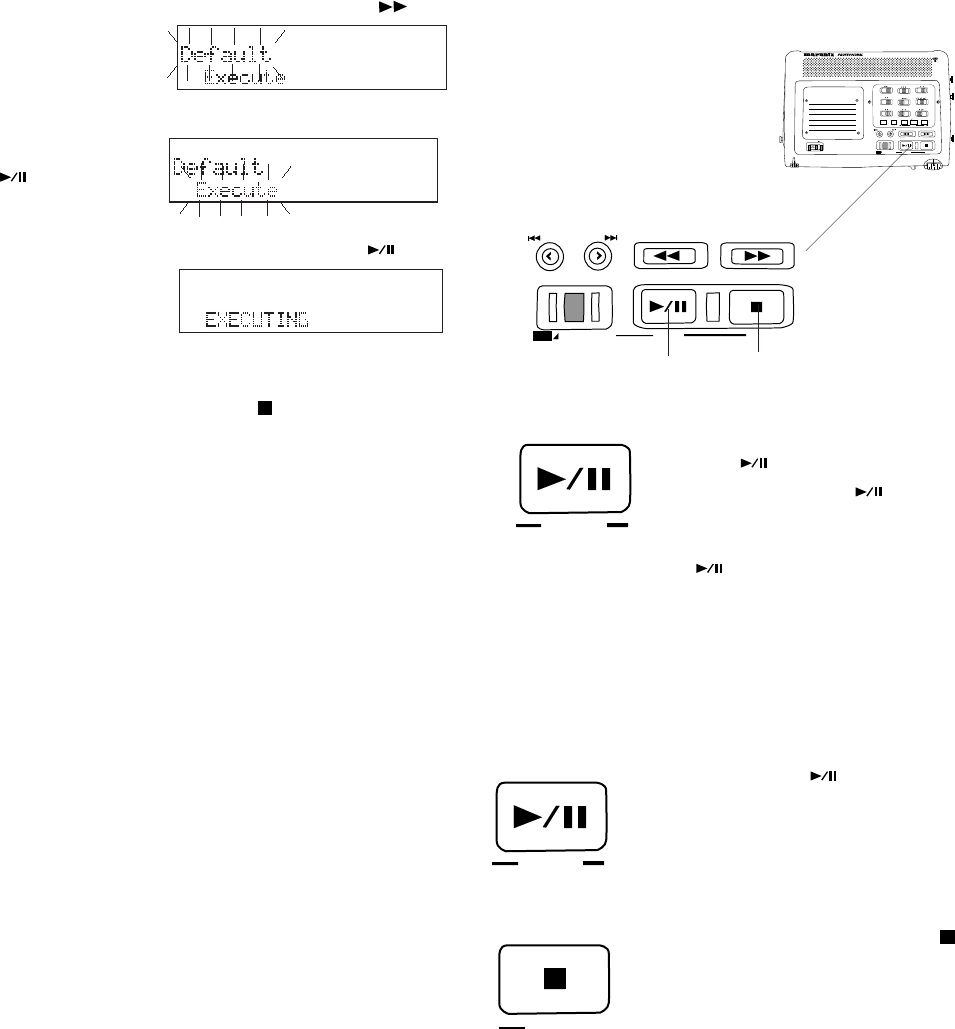
- 46 -
PLAY / PAUSE
ENTER
CANCEL
STOP
SOLID STATE RECORDER PMD671
POWER
MIC ATTEN
0dB -20dB
FLAT
ANC
LEVEL CONT.
LIMITER
ALC MANUAL
OFF ON
EDL PLAY
STEREO
L
AUDIO OUT
R
SOURCE FILE
MONITOR
OFF ON
PRE REC
MARK
A-B REPEAT
INPUT
EDIT
SINGLE
OFF ALL
OFF ON
INPUT LOCK
TRACK JUMP
MARGIN RESET
REC
UNDO
MENU/STORE ENTER CANCEL
PLAY / PAUSE STOP
USB
-
/
REW FWD
/
+
TRACK JUMP
MARGIN RESET
REC
UNDO
MENU/STORE ENTER CANCEL
PLAY / PAUSE STOP
USB
-
/
F.REV F.FWD
/
+
24 25
PLAY / PAUSE
ENTER
3. Press and release the F.FWD/+ button
24. PLAY/PAUSE but-
ton (playback)
ENTER button
(menu)
PLAY/PAUSE button
From stop, press and release to begin playback.
During playback, press and release to pause
playback.
During playback pause, press and release to
resume playback.
ENTER button
During menu functions, press
and release to accept the
current setting and switch to
the next menu item to be set.
25. STOP/CANCEL button
During recording, press and
release to stop recording and
end the track (file).
During playback, press and release to stop
playback and end the playback session. When
you resume, playback starts at the beginning of
the first track.
During menu operations, press and release to
cancel all entries made and return to stop mode.
until Default is
displayed.
4. With Default flashing, press and release the
ENTER button
. Execute
will be flashing*.
5. Press and release the ENTER button .
EXECUTING is
displayed briefly.
The PMD671 returns to stop mode.
*Press and release the STOP button to exit without
changing your Menu settings.
Controls and Connections
Top continued
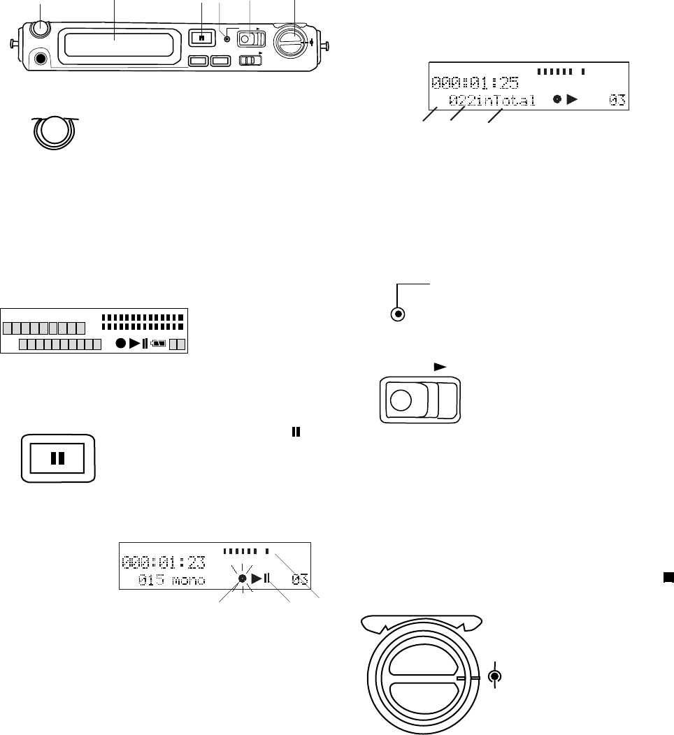
- 47 -
Front
REC PAUSE
DISPLAY LIGHT
REC
LEVEL
L
R
REC
HP/SPK VOLUME
PHONES
KEY LOCK
1 2 3 4 5 6
HP/SPK VOLUME
MARK
TRACK
TOTAL TRACK TIME
REC REMAIN kbps A-B L
R
-dB
PM
kHz
AM
INT
MIC
LINE
S.SKIP -dB
over
0
26
12
20
40
00
REC PAUSE
TRACK
TIMETRACK
MIC
INT -dB
00 40 20 12 62 0over
-dB
R
L
b a c
MARK
TIMETRACK
-dB
00 40 20 12 62 0 over
-dB
R
L
d e f
REC
REC
REC
LEVEL
R
L
1. HP/SPK VOLUME control
Turn to adjust the volume of
headphones plugged into the
PHONE jack or the built-in
speaker.
During playback, what is heard on the L or R
headphone depends on the recording. For a
Stereo or Dual Mono recording, the setting of the
AUDIO switch determines what is heard on
headphones.
2. Display
See Display on
page 55 for
details.
3. REC PAUSE button
During recording, push and
release to pause.
When paused, the REC indicator will flash.
Example
display
The Pause symbol (a) will be displayed.
The Record symbol (b) will flash in the display
The Level meter (c) will remain active.
To resume recording, slide the REC switch to the
right and release.
A REC PAUSE does not increment the track.
If the AUTO MARK switch is at ON, after a REC
PAUSE an EDL mark is added when recording is
resumed. The following is displayed for a couple
of seconds.
MARK (d) is displayed to indicate that the num-
ber (e) indicates the count of EDL marks.
"inTotal" (f) reminds you that EDL marks are
counted from the beginning the Flash memory
card, not the beginning of the current track.
4. REC indicator
Red indicator light is lit
and steady during
Record and flashing during Record pause.
5. REC switch
From Stop, slide to the
right and release to start
recording.
From REC PAUSE, slide to the right and release
to resume recording.
If Manual TR is on during recording, slide to the
right and release to increment the track (start a
new audio file).
To stop recording, press and release STOP .
6. REC LEVEL controls
Turn to adjust the
record level when the
LEVEL CONT. switch
is at MANUAL.
The inside control (Right channel) and outside
control (Left channel) turn together unless you
hold one while turning the other.
The optimum record level is when the level meter
goes as close to 0dB as possible but not OVER.
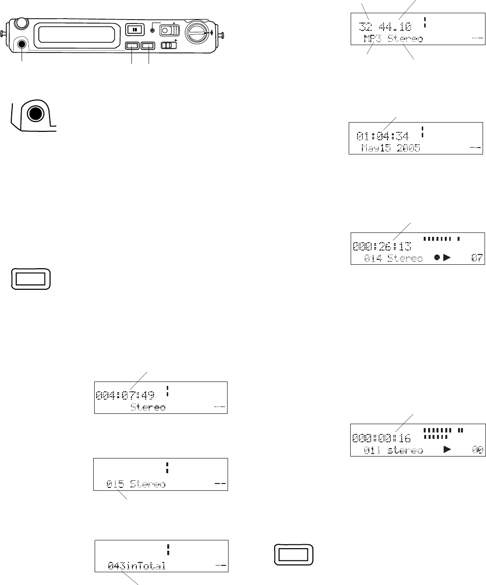
- 48 -
Front continued
REC PAUSE
DISPLAY LIGHT
REC
LEVEL
L
R
REC
HP/SPK VOLUME
PHONES
KEY LOCK
7 8 9
Adjust headphone volume with the HP/SPK
volume control.
Headphones are active during recording and
playback.
During playback, plugging in headphones mutes
the internal speaker.
PHONES
8. DISPLAY button
Press and release to tab
through alternate infor-
mation displays.
DISPLAY
Displays are slightly different in Stop, Record and
Play.
MIC
-dB
00 40 20 12 6 2 0 over
-dB
R
L
REMAINREC TIME
Example display.
MICTRACK
-dB
00 40 20 12 62 0over
-dB
R
L
After the first press,
track information
is displayed.
Total tracks on CF card.
After the second
press, EDL mark
information is
displayed.
MARK
-dB
00 40 20 12 6 2 0 over
-dB
R
L
Total EDL marks on CF card.
After the third
press, file
parameters are
displayed.
kHz
kbps
-dB
00 40 20 12 62 0over
-dB
R
L
bit rate sampling frequency
compression
algorithm
recording type
After the fourth
press, Date and
Time informa-
tion is dis-
played.
TIME
PM -dB
00 40 20 12 6 2 0 over
-dB
R
L
Current clock time
hours:minutes:seconds
After the fifth press, the display returns to the
default: remaining record time on the card.
remaining record time on card
During Record:
the default display
is Record time on
the current track.
The first press of the DISPLAY button switches
to remaining record time for the card.
The second press switches to file parameters.
The third press switches to date and time.
The fourth press returns to the default.
During Playback:
the default display
is playing time on
the current track.
The first press switches to file parameters.
The second press switches to date and time.
The third press returns to the default.
TRACK
TIMETRACK
LINE
-dB
00 40 20 12 6 2 0 over
-dB
R
L
Record time on track
During Stop:
TRACK
TIMETRACK
-dB
00 40 20 12 62 0over
-dB
R
L
playing time
9. LIGHT button
Press and release to
momentarily turn the Dis-
play light on.
Press and hold for three seconds to switch the
Display light on.
Press and release to switch the Display light
off.
LIGHT
7. PHONES jack
Plug stereo head-
phones in this jack.
Default display is
Remaining
record time for
the card.
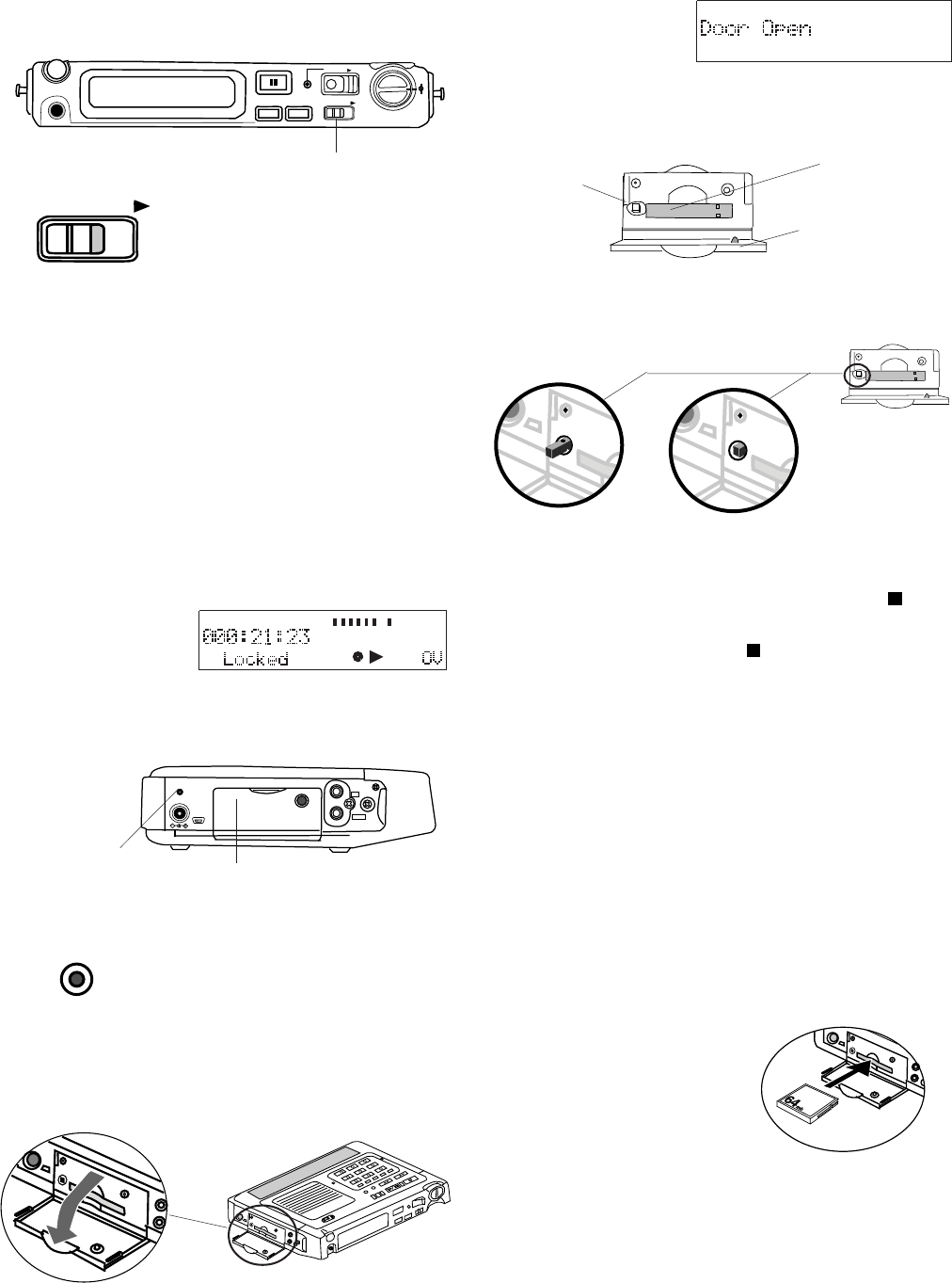
- 49 -
REC PAUSE
DISPLAY LIGHT
REC
LEVEL
L
R
REC
HP/SPK VOLUME
PHONES
KEY LOCK
10
Front continued
10. KEY LOCK switch
The KEY LOCK switch
secures the PMD671 in its
present state during
Record, Playback or Stop.
KEY LOCK
Slide the switch to the right to turn KEY LOCK on.
"Locked" is displayed for three seconds.
Only these controls will work:
Display LIGHT button.
POWER switch - Works during Playback or Stop.
PRE REC switch.
If you try to operate a button or switch that is
locked, "Locked" appears briefly in the display.
TRACK
TIMETRACK
MIC
INT
-dB
00 40 20 12 6 2 0 over
-dB
R
L
DIGITAL
IN
OUT
CHARGE
DC IN 15V
USB
11 12
CHARGE
ab
11. CHARGE indicator
The CHARGE indicator is
lit when an optional Ni-Cd
or
Ni-MH battery is charging.
12. CF card compartment
Pull the compartment door open to access the
CF card.
Door Open is
displayed.
Card eject
button
CF card slot
CF card door
Card eject button
The Card eject button has two positions: click
out (a) and click in (b).
To eject a CF card:
1. If recording or in playback, push STOP .
If other operations are in progress, cancel
them by pushing STOP or wait for them to
complete.
2. Open the CF card door*.
3. Push and release the Card eject button so it is
in the click out position (a).
4. Push the Card eject button from the click out
position to the click in position (b).
*Opening the CF card door turns the PMD671 off. If recording
is in progress, opening the CF card door automatically stops
recording and writes critical track information to properly
close the file before turning off. Close the CF card door to re-
start the PMD671.
To insert a CF card:
1. Push and release the Card eject button so it is
Slide the switch to the right to turn KEY LOCK
off. "Unlocked" is displayed for three seconds.
Example display:
Left side
The PMD671 automatically turns off.
in the click in posi-
tion (b above).
2. Fully insert the CF
card.
3. Close the CF card
door.
Note: If the CF card door won't latch, check that the Card
eject button is in the click in position (b above).
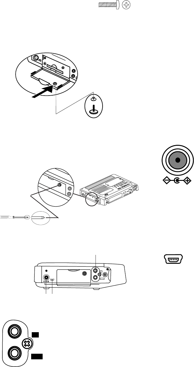
- 50 -
d
c
DIGITAL
IN
OUT
CHARGE
DC IN 15V
USB
13
14 15
DIGITAL
OUT
IN
DC IN 15V
USB
(3mm x
10mm long)
The supplied security screw
requires using a small Phillips
screwdriver to open the Memory
compartment door. The screw
reduces the possibility that the CF card will be mis-
placed or stolen.
1. Remove the plastic pin (c) and then the
retainer (d).
2. Add the screw. Tighten the screw enough so
that the screw cannot be removed with a
fingernail.
Security
Left side continued
13. DIGITAL IN/OUT jacks
RCA jacks for connect-
ing the PMD671 to an
audio component that
accepts or outputs digital
audio signals.
IN: Connect to the digital out of a digital audio
component. PCM audio data input at 44.1. 48,
88.2 and 96 kHz can be recorded.
Digi-IN must be selected using the INPUT button.
for the signal to be recorded. See page 18.
OUT: Connect to the digital in of a digital audio
component.
• Only files with sampling frequencies of 44.1,
48, 88.2 or 96 kHz can be output.
• Digital audio is only output during normal or
EDL playback.
• The receiving component must be able to
accept audio in SPDIF (IEC-958-II) format.
• The receiving component must be able to
accept a sampling frequency of 44.1, 48, 88.2
or 96 kHz.
14. DC IN 15V jack
Plug the supplied AC power
pack in this jack. The
power supplied is 1.0A at
15V AC.
The PMD671 automatically switches to adapter
power if it was running on battery power. If AC
power is interrupted by a power outage or un-
plugging the power pack, the PMD671 automati-
cally switches to battery power.
15. USB port
Plug the supplied USB cable in
this port and connect the other
end to your computer (PC or
MAC).
The USB (2.0) connection makes it easy to copy
audio files to your computer's hard drive or a CD.
This connection can only be made active when
the PMD671 is off (neither recording nor during
playback).
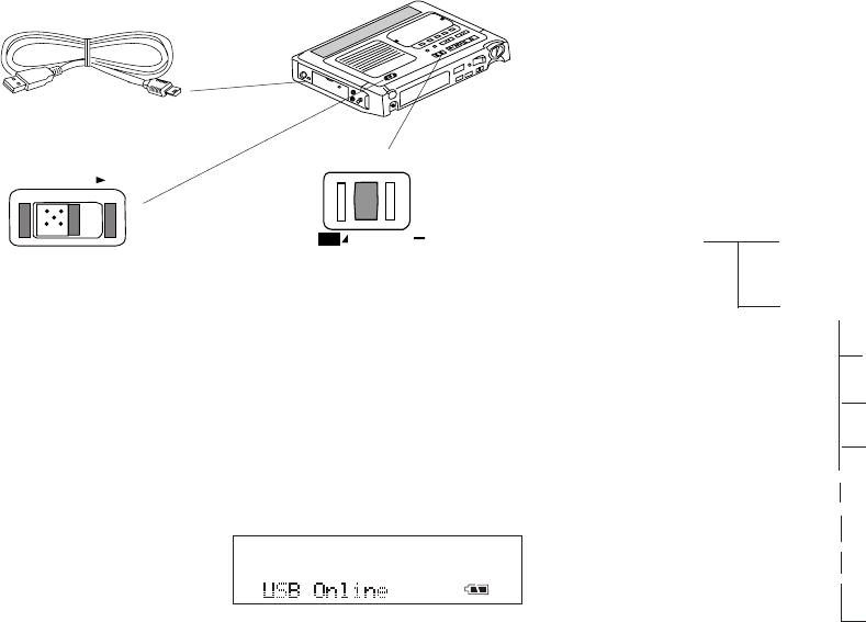
- 51 -
1. Connect the cable to the PMD671 and your
computer.
2. Slide the PMD671's POWER switch to the
right and release to power off.
3. Press and hold the USB MENU/STORE
button while you slide the POWER switch to
the right and release to power on.
The CF card in the PMD671 appears as a re-
movable device on your computer. The audio
files are in a folder named MPGLANG1.
CAUTION: Only copy audio files (tracks) to other
volumes. Do not modify or delete the EDL file. If
the EDL file is missing or damaged the PMD671
will be unable to recognize recorded tracks.
See the enclosed CD for demo PMDEdit soft-
ware for computer audio file manipulation.
PMDEdit is a full featured software suite de-
signed for Marantz Professional digital recorders.
It is available for purchase at www.d-mpro.com
or by calling toll free (866) 405-2154.
Power off and power the PMD671 back on to
resume recording or playback.
POWER
MARGIN RESET
MENU/STORE
i / O
How to connect via the USB port
1
2
3
1999.MP3
.
.
.
.
.
.
1003.MP3
1002.MP3
1001.MP3
MPGLANG1
PMD670.EDLRoot
A file titled PMD670.EDL and a folder (directory)
titled MPGLANG1 will appear on your computer.
Files within the MPGLANG1 folder are numbered
from 1001 through the number of tracks recorded
to a maximum of 1999. The file extension will be
.mp3, .wav, .bwf or .mpg depending on the Rec
Format parameters that were set for the record-
ing.
Diagram of file structure (assuming .mp3 files).
Changes made to file names or file structure on
your computer will prevent file recognition and
therefore playback in the PMD671.
However, audio files from your computer that are
renamed using the file names and file structure
above may be playable on the PMD671. For
example, if you name an mp3 audio file
1234.MP3 and place it in the MPGLANG1 folder,
the PMD671 may play it.
This display
appears:
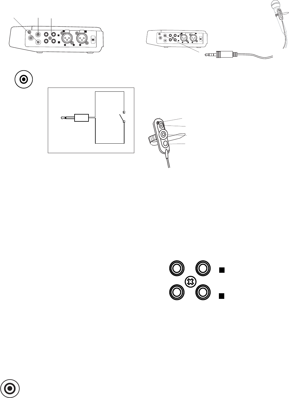
PUSH
PUSH
MIC
GND HOT COLD OFF
ON
+48V
PHANTOM
REMOTE 1
REMOTE 2
IN
LINE
1
3
21
3
2
R
R
R
R
L
L
L
L
1
1
2
2
3
3
REMOTE 1
- 52 -
16 17 18
REMOTE 2
PUSH
PUSH
MIC
GND HOT COLD OFF
ON
+48V
PHANTOM
REMOTE 1
REMOTE 2
IN
LINE
1
3
21
3
2
RR
RR
LL
LL
112233
a
b
c
d
L
R
LINE
IN
LINE
OUT
16. REMOTE1 jack
Plug a wired remote (not
supplied) in this jack.
Right side
Wiring
diagram
2.5 mm jack
the RemoteMode setting:
RemoteMode:
StartPause
From Rec or Playback Pause, switch remote
on to start recording. During record or play-
back, switch remote off to pause and on to
resume. If Auto Mark is On, an EDL mark is
added when recording resumes.
StrtStp TR
Start or stop recording. When re-started, a
new track is begun.
EDL Mark
During record or playback, switch remote to
on to add an EDL mark.
PWR REC
During POWER off, switch remote to on to
turn power on and begin recording.
During recording, switch remote to off to stop
recording and power off.
Manual TRK
During recording, switch remote to on to
increment the track. A new track is created at
that point. There is no break in recording.
See page 44 for instructions on how to set or
change the Remote Mode.
17. REMOTE2 jack
The REMOTE2 jack is for the
optional RC600 remote.
The RC600 is designed for
microphone interviews. It attaches to
your microphone.
The remote's four foot cord with a four contact
mini plug, plugs into the PMD671 while you carry
the PMD671 via its carry strap.
The RC600 does not require any menu changes
for use. The RC600 includes:
aAn indicator light:
• (green) lit and steady
during standby or stop
• (red) lit and steady while
recording
• (flashing red) during rec
pause
• (orange) flashes for 1/2 second when an
over peak level signal is input during record-
ing or rec pause, then it goes back to red
• (green flash) for 2 seconds when an EDL
mark is added during recording
bpress to pause recording
cpress to start/resume recording and to
manually increment tracks
dpress to add an EDL mark while recording
18. LINE IN/OUT
jacks
A switch
connected to
the 2.5mm mini
jack off (open)
and on
(closed) does
the following,
depending on
Plug external line
level audio devices
in these jacks.
LINE IN jacks
Plug Left and Right RCA audio cables in here to
connect to the output of an external unit.
To record, mono, stereo, or LR mono LINE input
must be selected in the input select menu. See
INPUT button.
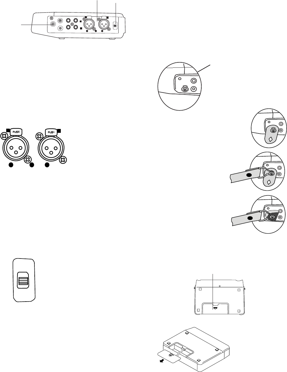
- 53 -
Right side continued
OFF: No microphone power is supplied.
Microphone recommendations
Professional condenser microphone(s) (which
require additional power either from phantom
power from the PMD671 or another source) are
recommended because they provide greater
sensitivity and higher quality audio recording.
PHANTOM
+48V
ON
OFF
19 20
PUSH
PUSH MIC
GND HOT COLD OFF
ON
+48V
PHANTOM
REMOTE 1
REMOTE 2
IN
LINE
1
3
21
3
2
R
R
R
R
L
L
L
L
1
1
2
2
3
3
21
21. Carry studs
Attach the supplied carry
strap to these studs.
REMOTE
2
REMOTE
1. Push the end of a strap
retainer with a round hole
onto a carry stud.
Installing the carry strap
2. Attach the carry
strap.
22
adapter (not supplied) from
PHONE to XLR.
20. PHANTOM +48V switch
Switch to ON to provide 48V
of power for a condenser
microphone(s).
ON: +48V is supplied to
power condenser
microphone(s).
3. Close the strap
retainer by 'buttoning'
the other end of strap
retainer over the
carry stud.
Bottom
22. Battery com-
partment
Press and slide
at arrow to open
the Battery
compartment.
REMOTE
2
REMOTE
REMOTE
2
REMOTE
REMOTE
2
REMOTE
3COLD
2HOT
2
31
2
31
1GND
LR
MIC
Dynamic microphone(s) can be used but do not
yield optimum audio quality recordings.
Consult with your local dealer to select the
appropriate microphone(s) for your specific
application. They can demonstrate the various
performances and characteristics of microphones
for your use.
.
19. MIC IN jacks
Plug external micro-
phones in these jacks.
MIC must be selected
using the INPUT
button.
For mono recording. use the Left jack.
To record stereo with MIC input or LRmono with
MIC input, use both jacks.
Notes:
• XLR pin out is 1 ground, 2 hot and 3 cold.
• Microphones with a PHONE jack can be used with an
4. Repeat 1-3 for other carry stud.
LINE OUT jacks
Plug Left and Right RCA audio cables into these
jacks to connect to the input of an amplifier or
other external unit.
During playback, the output on the L or R channel
depends on the recording. For a Stereo or Dual
Mono recording, the setting of the AUDIO OUT
switch determines the output channel(s).
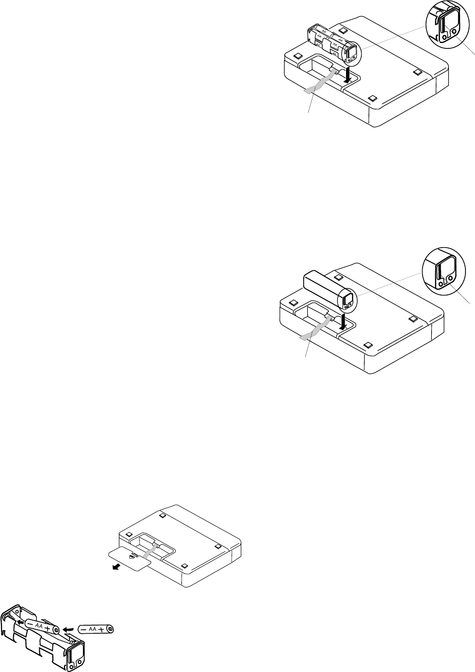
- 54 -
Battery power
The PMD671 can operate on several types of
battery power.
Hint:
Keep fully charged batteries in the PMD671
when recording using AC power because as
much as 30 seconds of your recording could be
lost if AC power is interrupted.
Eight AA alkaline batteries and the supplied
battery holder can be used. Alkaline batteries
can power recording or playback for about *6
hours.
AA size rechargeable Ni-Cd or Ni-MH batteries
can be used in the supplied battery holder, but
they cannot be recharged with the PMD671's
built in charger.
An optional Ni-Cd battery model RB1100 can be
charged in the PMD671. Ni-Cd batteries can
power recording or playback for about *5 hours.
An optional Ni-MH (Nickel metal hydride) battery
model RB1651 can be used and recharged with
the PMD671's built-in charger. Ni-MH batteries
can power recording or playback for about *7
hours.
*Using compact flash media.
Installing AA size batteries:
Power off and turn the PMD671 upside down.
Press and push in the direction of the arrow to
remove the battery
compartment
cover.
Install 8 AA size
batteries to the
battery holder with the -
ends towards the
springs.
Install the battery holder with tab as shown and
over the ribbon for easy battery holder removal.
tab
ribbon
Installing an optional Ni-Cd or Ni-MH battery
tab
ribbon
Replace the battery compartment cover**.
Install the battery with tab as shown and over
the ribbon for easy battery removal**.
Charging the optional Ni-Cd battery
• Load the Ni-Cd battery correctly in the
battery compartment.
• Connect the AC power pack and plug into
power supply.
• Select Ni-Cd in the Batt type menu (page
30).
• Power the PMD671 on, then off for the
charging cycle to begin.
• The PMD671 must be off during battery
charging.
While charging (about 3 hours), the CHARGE
indicator will be lit and steady.
When the Ni-Cd battery charge cycle is com-
plete, the CHARGE indicator will be off.
**When changing battery type, be sure you change
the Batt type menu setting for optimal battery
performance.
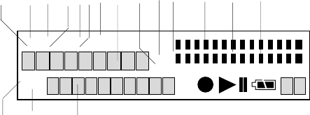
- 55 -
MARK
TRACK
TOTAL TRACK TIME
REC REMAIN kbps A-B L
R
-dB
PM
kHz
AM
INT
MIC
LINE
S.SKIP -dB
over
0
26
12
20
40
00
1 2 3 4 5 6 7 8 9 10 11 12 13 14
15 16 17
Display settings etc. Associated labels are display
items 1-7, 9 and 10.
9. AM / PM label
Displays AM or PM when clock time is dis-
played.
10. kHz label
The kHz label appears to indicate that the
last five places in the upper alphanumeric
display show frequency in kilohertz.
11. L -dB R level meter labels
L is the label for the Left (upper) level meter.
-dB is the label for the center level meter
scale in decibels.
R is the label for the Right (lower) level
meter.
12. Upper level meter
The louder the sound input to the recorder on
the Left channel, the more bars are dis-
played.
13. Decibel scale
The scale in dB (decibels) for the upper and
lower level meters.
14. Lower level meter
The louder the sound input to the recorder on
the Right channel, the more bars are dis-
played.
15. TRACK label
The TRACK label appears to indicate that the
number displayed on the left of the lower
alphanumeric display is the track number.
16. MARK label
The MARK label appears to indicate that the
number displayed on the left of the lower
alphanumeric display is the EDL Mark num-
ber.
17. Lower alphanumeric display
Displays a variety of information including
remaining recording algorithm, date, track
number, number of tracks on CF card, EDL
Mark number, number of EDL Marks on CF
card etc. Associated labels are display items
15 and 16.
1. REC label
The REC label appears to indicate TOTAL
REC TIME or REC TIME REMAINING dis-
played on the upper alphanumeric display.
2. TOTAL label
The TOTAL label appears to indicate TOTAL
REC TIME or TOTAL REC TIME REMAINING
displayed on the upper alphanumeric display.
3. TRACK label
The TRACK label appears with other labels in
this area to indicate TRACK TIME displayed
on the upper alphanumeric display.
4. REMAIN label
The REMAIN label appears to indicate REC
TIME REMAINING or TOTAL REC TIME
REMAINING displayed on the upper alphanu-
meric display.
5. TIME label
The TIME label appears to indicate REC TIME
REMAINING, TOTAL REC TIME REMAINING
or TRACK TIME displayed on the upper
alphanumeric display.
6. kbps label
The kbps label appears to indicate that the
first five places in the upper alphanumeric
display are kilobytes per second.
7. A-B label
A- indicates that the beginning (A point) of an
A-B loop has been set.
A-B indicates that the ending (B point) of an
A-B loop has also been set.
8. Upper alphanumeric display
Displays a variety of information including
remaining recording time, clock time, menu
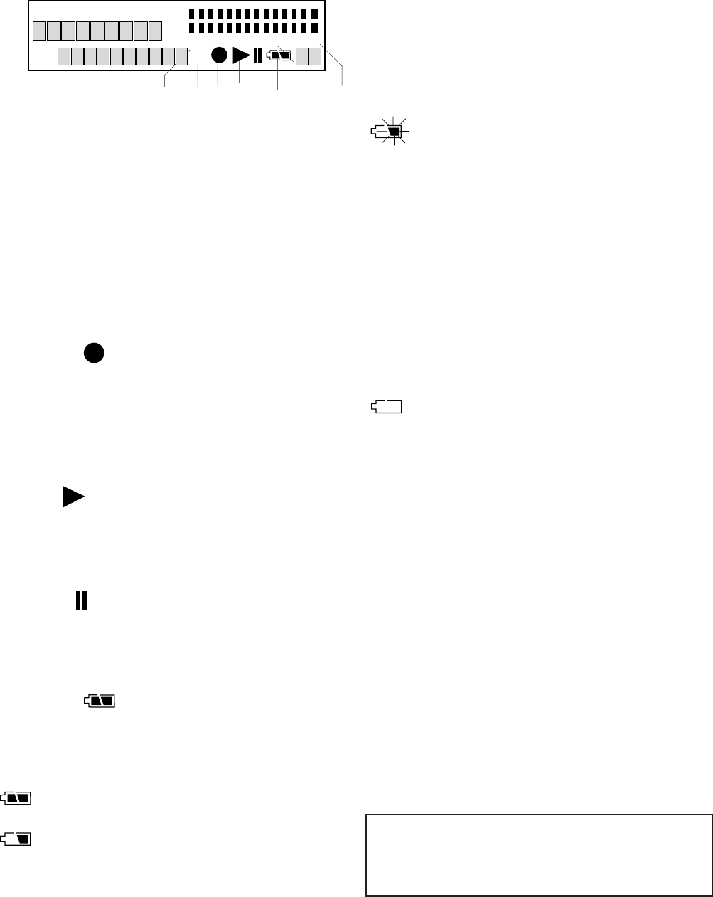
- 56 -
18. MIC / INT MIC label
The MIC label appears when external micro-
phones are selected.
The INT MIC label appears when input se-
lected for recording is the internal micro-
phone.
19. LINE label
The LINE label appears when input(s) se-
lected for recording is (are) the LINE IN jacks.
20. Record
The Record symbol appears when the
PMD671 is in record mode. It appears with
the Play symbol when recording. It appears
with the pause symbol and flashing when in
record pause.
21. Play
The Play symbol appears when the PMD671
is in playback, playback pause, recording or
record pause.
22. Pause
The Pause symbol appears when the
PMD671 is in playback pause or record
pause.
23. Battery
When on battery power, the Battery symbol
appears in most displays to indicate battery
charge.
indicates that the battery charge is good.
indicates that the battery charge is getting
low and there is approximately 5 to 10 min-
utes of record or playback time available.
18 19 20 21 22 23 24 25 26
flashing indicates that the battery has
approximately 1 to 3 minutes of record or
playback time remaining.
The CHARGE indicator light will flash. If
BEEP is set to On, the PMD671 will also
beep.
If the PMD671 continues to operate, it will
automatically shut down. If recording, it will
write track information, stop recording and
power off. If in playback, it will stop playback
and power off.
indicates that the battery charge is de-
pleted.
24. S.SKIP label
The S.Skip label appears when Silent Skip is
enabled.
25. Margin level
The Margin level is displayed. The PMD671
holds this display at the highest level
achieved during the current recording. If
more than 0 dB, OV is displayed. To reset
the Margin level, press and release the
MARGIN RESET button.
26. -dB label
The -dB label applies to the Peak level
display.
Care and Maintenance
MARK
TRACK
TOTAL TRACK TIME
REC REMAIN kbps A-B L
R
-dB
PM
kHz
AM
INT
MIC
LINE
S.SKIP -dB
over
0
26
12
20
40
00
Use a soft cloth slightly moistened with mild
detergent solution.
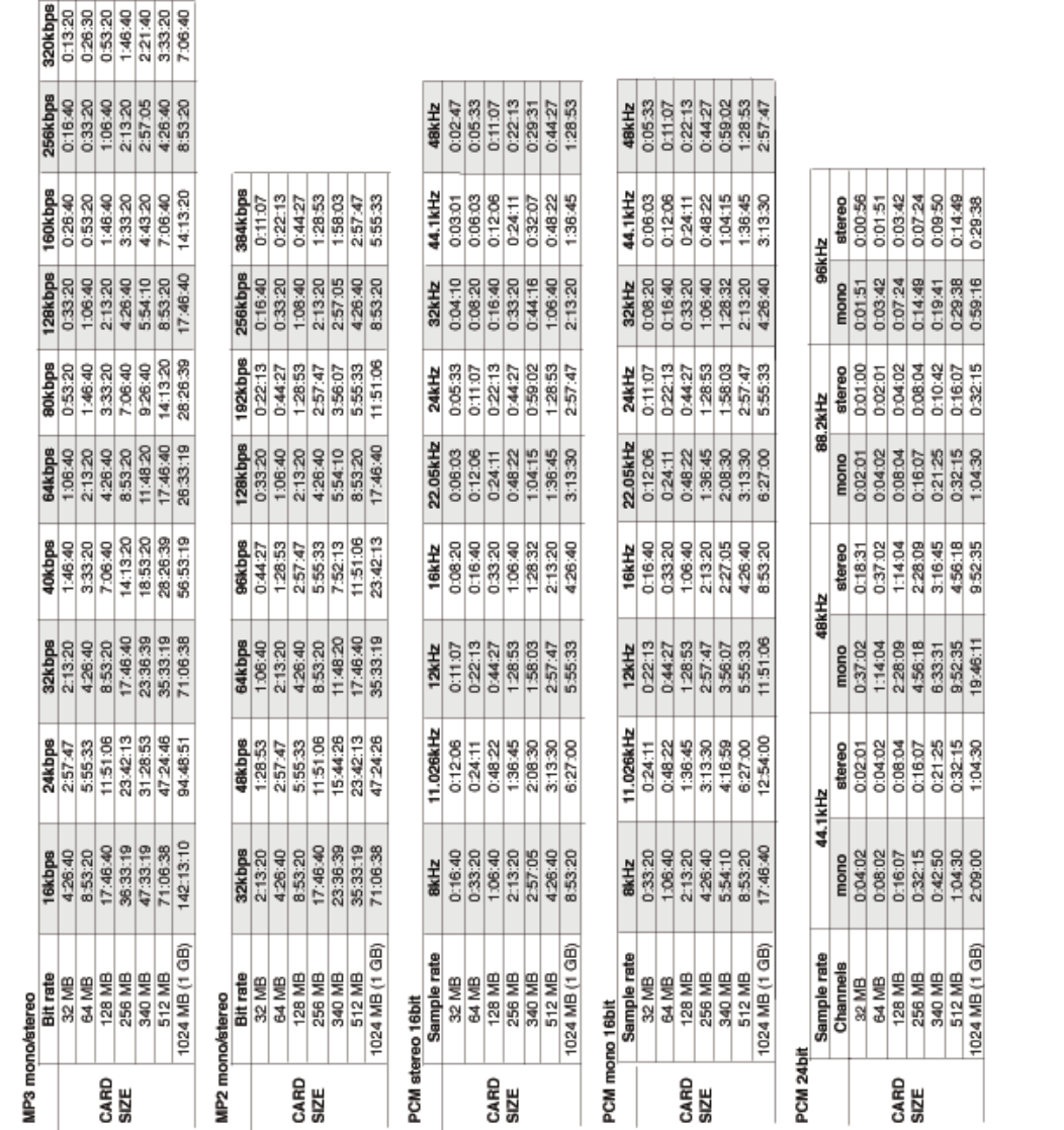
- 57 -
Recording time chart
The recording time available (Hours:Minutes:Seconds) on a CF card depends on the size of the card in mega-
bytes (MB), the recording type (PCM, MP2 or MP3), mono or stereo, bit rate, sample rate, and byte size (8, 16, or
24). This recording time chart lists approximate recording times based on those factors.
All times are approximate.

Rec Format charts
- 58 -
16 bit
PCM
24 bit
16 bit
mp3/bwf
(80, 64, 40, 32, 24, 16)
24, 22.05, 16
mp3/bwf
(160, 128, 80, 64, 40, 32)
48, 44.1, 32
MP3
mpg/bwf
(192, 128, 96, 64, 48, 32)
48, 44.1, 32
MP2
16, 12, 11.025, 8
48, 44.1, 32, 24, 22.05,
wav/bwf
96, 88.2, 48, 44.1
Mono
BWF ext.
wav/bwfmp3/bwf
mp3/bwf
mpg/bwf
(160, 128, 80, 64, 40, 32)
24, 22.05, 16
(320, 256, 160, 128, 80, 64)
48, 44.1, 32
MP3
(384, 256, 192, 128, 96, 64)
48, 44.1, 32
MP2
PCM
Stereo
24 bit
wav/bwf
16, 12, 11.025, 8
48, 44.1, 32, 24, 22.05,
96, 88.2, 48, 44.1
File ext.
Fs kHz and
(Bit rate kbps)
Audio
Format
Channel(s)
16 bit
PCM
24 bit
16 bit
PCM
24 bit
mp3/bwf
(160, 128, 80, 64, 40, 32)
48, 44.1
MP3
mpg/bwf
(192, 128, 96, 64, 48, 32)
48, 44.1
MP2
wav/bwf
Mono
wav/bwf
mp3/bwf
(320, 256, 160, 128, 80, 64)
48, 44.1
mpg/bwf
(384, 256, 192, 128, 96, 64)
48, 44.1
wav/bwf
48 , 44.1
96, 88.2, 44, 44.1
MP3
MP2
Stereo
96, 88.2, 44, 44.1
48 , 44.1
BWF ext.File ext.
Fs kHz and
(Bit rate kbps)
Audio
Format
Channel(s)
Analog inputs
Digital input (shaded values set by input source)

Menu defaults
*Default when the function has been set to On.
CompressedUncompressedUncompressedUncompressedCompressedCompressed
MusicHighest QualityHigh QualityHighest QualityMeetingAudio Application:
---------------Default
0000000000000000000000000000000000006-digit ASCII codeID3OrgRef
0000000000000000000000000000000000006-digit ASCII codeID2Origin
0000000000000000000000000000000000006-digit ASCII codeID1Dscrpt
StartPauseStartPauseStartPauseManual TRKEDL MarkStartPausePWR REC/Manual TRK
StartPause/StrtPausTR/EDL Mark/Remote
OnOnOnOnOnOnOn/OffSinglePly
OffOffOffOffOffOffOn/OffS.Monitor
-40dB*-40dB*-40dB*-40dB*-40dB*-40dB*-60 - -20dB (5dB steps)
20 msec*20 msec*20 msec*20 msec*20 msec*20 msec*5 - 95 msec (5 msec steps)
OffOffOffOffOffOffOn/OffAuto Cue
-40dB*-40dB*-40dB*-40dB*-40dB*-40dB*-60 - -20dB (5dB steps)
3 sec*
3 sec*3 sec*3 sec*3 sec*3 sec*1 - 5 sec (1 sec steps)
OffOffOffOffOffOffOn/OffSilentSkp
OffOffOffOffOffOffOn/OffSeamls Ply
5 min*5 min*5 min*5 min*5 min*5 min*1/5/10/15/30 min, 1/2/6/8/12/24 hrs
OffOffOffOffOffOffOn/OffAuto TRK
OnOnOnOnOnOnOn/OffManualTR
OnOnOnOnOnOnOn/OffAuto Mark
MonoMonoMonoMonoMonoMonoMono/LRmonoMono Mode
StereoStereoStereoStereoStereoStereoStereo/L-Stereo/0-20dBSt Mode
OffOffOffOffOffOffOn/OffPupPreRec
OffOffOffOffOffOffOn/OffVerify
MonitorMonitorMonitorMonitorMonitorMonitorMonitor, TimeShftRAW Mode
wavwavwavwavwavwavwav/bwf (BWF Extension)
mp3
wavewavewavemp3mp3wave/BWF/mp2/mp3 (File Format)
160N/AN/AN/A32128bit rate (kbps)
44.14844.144.144.144.1Fs (kHz)
MP3PCMPCMPCMMP3MP3PCM/MP2/MP3
StereoStereoStereoStereoMonoStereoStereo/MonoRecFormat
Preset 3Preset 2Preset 1Preset 3Preset 2Preset 1
11
1/2/3Preset
AlkalineAlkalineAklaline/Ni-Cd/Ni-MhBatt type
On
On
On/Off
Beep
D/M/Y
M/D/Y
M/D/Y, D/M/Y
DateForm
AM 0:00
AM 0:00
AM/PM 0:00 - 11:59
11
1 - 31
JAN
JAN
JAN - DEC
20052005
2003 - 2099Date Time
Default Setting (Europe)
Default Setting (America)
Selection rangeDisplay
A.PowOff Yes/No Yes Yes
- 59 -

- 60 -
TROUBLESHOOTING
Should faults occur, it is often unnecessary to consult
your dealer or technical service department. On the
basis of the following checks, you may be able to
rectify a number of conditions yourself without diffi-
culty. If the condition cannot be remedied after the
following check, please consult your dealer or contact
Marantz Professional toll free at (866) 405-2154.
The PMD671 does not turn on
Check power
• install fresh batteries
• check AC adaptor connections
The PMD671 turns on then turns itself off
• install fresh batteries
The PMD671 seems to record, but there is no sound
on playback
• check input setting (For example, if LINE input is
selected and no input is connected to the LINE IN
jacks, the PMD671 will record silence.)
The PMD671 will not playback
• check EDL switch, if ON switch to OFF
No audio playback through headphones or internal
speaker
• check HP/SPK VOLUME control setting
• check a different track or CF card
The PMD671 will not record
• try a different CF card
• check that the maximum of 999 tracks have not
been recorded
• check that the PMD671 acknowledges the CF
card
No signal from microphone input
• check input selection
• check REC level control settings
• check if microphone(s) require Phantom power
Excessive noise
• check cable connections
• turn off power to the PMD671, unplug the AC
adapter, remove batteries, and then reinstate
power to the unit (Complete Reset).
Playback on a PC results in poor sound
• check quality of PC sound card and program
• check frequency conversion program*
*The PMD671 records audio files with a sampling
frequency of 48kHz. Some PC programs convert
the files to 44.1kHz (using a sample rate con-
verter). Only high quality sample rate converters
should be used.
Cannot Read After Write (display says Cannot . . ,)
Cannot Time Shift (display says Cannot . . .)
• Read After Write/Time Shift features are not
available in 24 bit recording
PC cannot read files
• check if the files are MP2 or MP2 with a .wav file
extension. Some PC's cannot interpret this
combination. Try renaming the MP2 file so it has
a .mp2 or .mp3 file extension.
• check the capability of the PC program
Some playback and editing programs do not
support MP2/MP3, Broadcast Wave (.bwf) or 24-
bit formats. Consult the Marantz Professional web
site at www.d-mpro.com for links to programs that
support MP2/MP3 and Broadcast Wave Format.
The rechargeable battery is not recharging
• check that the CHARGE indicator is lit and steady
during charging and off when charging is com-
plete
• check AC power pack connections
• check that Power is turned off on the PMD671
The rechargeable battery life is low
• make sure you fully charge and discharge the Ni-
Cd battery during each charge cycle
• replace battery
Media cards that are heavily used should be occa-
sionally reformatted to avoid audio problems due to
fragmentation.
If the PMD671 exhibits erratic behavior, the micropro-
cessor can be reset by, powering off, disconnecting
AC power and removing batteries.
Error Messages
Wave format error was detected during PCM file playback.
Can not… E7
Cannot Card Check because there is too little remaining card capacity.
Can not… E6
F.FWD/F.REV or Seek+/- search is not available on the VBR (Variable Bit Rate) file.
Can not… E5
Verify is not available during recording with MP2, or 24 bits and 96/88.2kHz PCM
Can not… E4
96/88.2 kHz PCM.
Read After Write is not available during recording with MP2, or 24 bits and
Can not… E3
or audio formats i.e. MP2 and MP3.
Time Shift Playback is not available between tracks having different sampling frequenciesCan not… E2
Time Shift Playback is not available on the CF card which was recorded on the PMD660.
Can not… E1
DSP processing error.
DSP ERROR
A verify error was detected during recording while the menu choice Verify is "On".
Verify Err
EDLERROR-A" A or B point for EDL A-B loop was not found.
"NO_EDL
digital input, or a corrupt file format is set up.
A digital audio signal with a corrupt sample rate was received during recording with Unsupport
A corrupt digital audio signal was received during recording with digital input.
UnLock
Others
Accessing speed of the CF card is not suitable.No_Good
The number of EDL marks on the card has reached the 255 maximum.Mark_255
A track for which playback is not available was output.Can not…
The number of tracks on the CF card has reached the 999 maximum.FULL_999
Correct file does not exist.NO_FILE
Formatting failure.Format Fail
FormatOnPC" CF card is not formatted.
"You Need
Remaining capacity of CF card is less than a few kbytes.FULL_CARD
Initializing of CF card failure or track information renewal failure.UNFORMAT
No CF card inserted, or card is not detected.NO_CARD
CF Card
Description Display

SPECIFICATIONS*
Digital audio system
System ........................................ Solid State Recorder
Usable Media ................. CF memory/Microdrive cards
Recording and media methods
.mp2......................... MPEG1 Layer II compression
.mp3........................ MPEG1 Layer III compression
.mp3 ...................... MPEG2 Layer III compression*
*for all half sample rates.
PCM ....................................... 16/24 bit linear PCM
Recording bit rate (selectable)
MP2 mono .................. 192, 128, 96, 64, 48, 32 kbps
MP2 stereo ............... 384, 256,192,128, 96, 64 kbps
MP3 mono ...... 160, 128, 80, 64, 40, 32, 24, 16 kbps
MP3 stereo .. 320, 256, 160,128, 80, 64, 40, 32 kbps
Sampling frequency
Analog
24bit PCM ........................... 96, 88.2, 48, 44.1 kHz
16bit PCM .....................................48, 44.1, 32, 24,
....................................22.05, 16, 12, 11.025, 8 khz
MP2 ............................................. 48, 44.1, 32 kHz
MP3 ..................... 48, 44.1, 32 , 24, 22.05, 16 kHz
Digital ..................................... 96, 88.2, 48, 44.1 kHz
Number of channels ...................... 2 (stereo), 1 (mono)
Frequency response ........... 44kHz (-0.5dB, fs=96kHz)
Signal-to-Noise Ratio
IEC-A weighted ....................................... LINE 92 dB
MIC 65 dB
Total Harmonic Distortion
at 0 VU (PCM)........................................ LINE 0.01%
MIC 0.03%
Dynamic Range................................................... 94 dB
Inputs
MIC IN L/R
Type ....................... XLR (1:GND, 2:HOT, 3:COLD)
Input Sensitivity (MIC) ............ 1.2 mVrms/3 kohms
LINE IN L/R
Type ......................................................... RCA jack
Input Sensitivity ................... 300 mVrms/22 kohms
DIGITAL IN
Type ......................................................... RCA jack
Input impedance ....................................... 75 ohms
Standard input level .................................. 0.5 Vp-p
Sampling frequency ............ 96, 88.2, 48, 44.1 kHz
Format .............................. SPDIF (IEC 958 TypeII)
Outputs
LINE OUT L/R
Type ......................................................... RCA jack
Standard level ...................... 2 Vrms max./2 kohms
DIGITAL OUT
Type ......................................................... RCA jack
Output impedance .................................... 75 ohms
Standard output level ................................ 0.5 Vp-p
Sampling frequency ............ 96, 88.2, 48, 44.1 kHz
Format .............................SPDIF (IEC-958 Type II)
- 61 -
General
Headphone Output power ............... 20 mW/32 ohms
Speaker Output power ...................... 70 mW/4 ohms
Phantom power ......................................... +48V/7mA
Power consumption
Recording/Playback......................................... 6 W
Charging ................................................ 12 W max
Standby (battery driven) ............................ 2.9 mW
Battery life (Alkaline) ........................ 6 hours (typical)
Dimensions
Width ............................................. 264 mm (10.4")
Height ................................................ 55 mm (2.0")
Depth ............................................... 185 mm (7.3")
Weight ....................................... 1.3 kg (2 lbs. 14 oz.)
Included accessories
AC adapter ...........................................................1
Battery holder ....................................................... 1
Carry strap ............................................................ 1
Carry strap retainers ............................................. 2
Screws (ISO 3x10 mm) ........................................3
Plastic pin and retainer .........................................1
USB cable .............................................................1
User Guide ...........................................................1
Optional accessories** [availability]
Ni-Cd battery pack ..................................... RB1100
Ni-MH battery pack .................................... RB1651
Carrying cover (vinyl) ................................ CLC670
Carrying bag [US, Europe, only] ............... PRC300
Professional reporter's bag
[US, Europe, only] .............................. PRC600
Attache carrying case [US only] ..................CA200
**See www.d-mpro.com for details.
*Specifications subject to change without notice.
Record setting recommendations
Recording a meeting
LEVEL CONT. switch at ALC.
ANC switch at .
Factory default settings.
Input: INT MIC mono or MIC mono
Menu settings:
Preset 2
Recording music
LEVEL CONT. switch at MANUAL.
ANC switch at FLAT.
Input: MIC stereo
Menu settings:
Preset 1
Menu settings (highest quality):
Preset 3
- 62 -
LIMITED WARRANTY
Your Marantz Professional product is warranted against
manufacturer defects in material and workmanship for a
period of one year parts and labor.
Except as specified below, this warranty covers defects in
material and workmanship. The following are not covered
under warranty:
1. Damage, deterioration, malfunction or failure to meet
performance specifications resulting from:
a) Accidents, acts of nature, misuse, abuse, neglect or
unauthorized product modification.
b) Improper installation, removal or maintenance, or
failure to follow supplied instructions.
c) Repair or attempted repair by a non-Marantz
authorized agent.
d) Any shipment (claims must be presented to the
carrier).
e) Any cause other than a defect of manufacturing.
2. Cleaning, check-ups with no fault found or changes
incurred for installation, removal or reinstallation of the
product.
3. Any serialized product on which the serial number has
been defaced, modified or removed.
4. Batteries and battery chargers.
5. Accessories, including but not limited to: cables, mount-
ing hardware and brackets, cleaning accessories, power
cords and adapters, and carry cases.
6. Products purchased outside of the United States, its
possessions or territories.
Non-transferable warranty
This Warranty may be enforced only by the original pur-
chaser.
What We Will Pay For
We will pay for all labor and material expenses for items
covered by the warranty.
How You Can Get Service
1. If your unit needs service in the USA, contact our
service referral at the appropriate telephone number
indicated below. We will advise you of the name and
location of one or more authorized service centers
from which service may be obtained. Please do not
return the unit directly to us.
2. You must pay any shipping charges if it is necessary to
ship the product for service. If the necessary repairs
are covered by the warranty, we will pay return
shipping charges to your location anywhere in the
United States or its territories.
3. Whenever warranty service is required, you must
present the original dated sales receipt or other proof
of date purchased.
Limitation of Implied Warranties
All implied warranties, including warranties of merchantabil-
ity and fitness for a particular purpose, are limited in
duration to the length of this warranty.
Exclusion of Damages
Liability for any defective product is limited to repair or
replacement of the product at manufacturer’s option.
Manufacturer shall not be liable for damage to other
products caused by any defects in Marantz products,
damages based on inconvenience or loss of use of the
product, or any other damages, whether incidental, conse-
quential, or otherwise.
Some States do not allow limitations on how long an implied
warranty lasts and/or do not allow the exclusion or limitation
of incidental or consequential damages, so the above
limitations and exclusions may not apply to you.
How State Law Relates to the Warranty
This warranty gives you specific legal rights, and you may
have other rights which may vary from State to State.
Marantz Professional Service Number:
Marantz Professional Factory Service (630) 741-0330, toll
free within the US (866) 405-2154.
This warranty is enforceable only in the United States and
its possessions or territories.

Marantz is a registered trademark.
®
2005/3
