Marantz Sr7200 Users Manual SR 14EXU DFU (E)
SR7200 to the manual 1cfa1cff-3ca0-4ed2-90ad-8389f1aa3dee
2015-02-03
: Marantz Marantz-Sr7200-Users-Manual-466585 marantz-sr7200-users-manual-466585 marantz pdf
Open the PDF directly: View PDF ![]() .
.
Page Count: 39
- SR7200U DFU (ENG) 2/3.pdf
- SR7200U DFU (ÿNG) 3/3 Other.pdf
- SR7200U DFU (FRN) 1/2.pdf
- INTRODUCTION
- DESCRIPTION
- CARACTERISTIQUES
- PANNEAU AVANT
- CONNEXIONS AU PANNEAU ARRIERE
- TELECOMMANDE RC7200SR
- FONCTIONNEMENT DE LA TキイOMMANDE
- CONFIGURATION
- SYSTEME DE MENU DユAFFICHAGE SUR ECRAN
- OSD MAIN MENU (Menu principal)
- SYSTEM SETUP
- INSTALLATION DES ENCEINTES
- SURROUND MODE (Mode dユambiance)
- CHANNEL LEVEL CONTROL (Commande de niveau de canal)
- MULTI ROOM SETUP (Configuration pi颪es multiples)
- OPERATIONS ELEMENTAIRES
- ECOUTE DU SYNTONISEUR
- REPRODUCTION
- AUTRES FONCTIONS
- REGLAGE DE LA MINUTERIE DユARRET AUTOMATIQUE
- FONCTION DE MISE SOUS/HORS TENSION AUTOMATIQUE PAR LA TELEVISION
- SELECTEUR PIECES MULTIPLES
- INFORMATIONS DE LユAFFICHAGE SUR ECRAN
- SR7200U DFU (FRN) 2/2.pdf
- SR7200U DFU (ESP) 2/2.pdf

Model SR7200 User Guide
AV Surround Receiver
R

vii
CAUTION
RISK OF ELECTRIC SHOCK
DO NOT OPEN
CAUTION: TO REDUCE THE RISK OF ELECTRIC SHOCK,
DO NOT REMOVE COVER (OR BACK)
NO USER-SERVICEABLE PARTS INSIDE
REFER SERVICING TO QUALIFIED SERVICE PERSONNEL
The lightning flash with arrowhead symbol,
within an equilateral triangle, is intended to
alert the user to the presence of uninsulated
“dangerous voltage” within the product’s
enclosure that may be of suffi-cient magnitude
to constitute a risk of electric shock to persons.
The exclamation point within an equilateral
triangle is intended to alert the user to the
presence of important operating and
maintenance (servicing) instructions in the
literature accompanying the appliance.
WARNING
TO REDUCE THE RISK OF FIRE OR ELECTRIC SHOCK,
DO NOT EXPOSE THIS APPLIANCE TO RAIN OR MOISTURE.
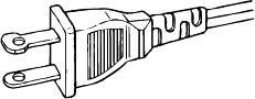
CAUTION:
TO PREVENT ELECTRIC SHOCK, MATCH WIDE
BLADE OF PLUG TO WIDE SLOT, FULLY INSERT.
ATTENTION:
POUR ÉVITER LES CHOCS ÉLECTRIQUES,
INTRODUIRE LA LAME LA PLUS LARGE DE LA FICHE DANS LA
BORNE CORRESPONDANTE DE LA PRISE ET POUSSER
JUSQU’AU FOND.
NOTE TO CATV SYSTEM INSTALLER:
This reminder is provided to call the CATV (Cable-TV) system installer’s attention to Article 820-40 of the NEC, that provides
guidelines for proper grounding and, in particular, specified that the cable ground shall be connected to the grounding system of the
building, as close to the point of cable entry as practical.
NOTE:
This equipment has been tested and found to comply with
the limits for a Class B digital device, pursuant to Part 15
of the FCC Rules. These limits are designed to provide
reasonable protection against harmful interference in a
residential installation. This equipment generates, uses
and can radiate radio frequency energy and, if not
installed and used in accordance with the instructions,
may cause harmful interference to radio communica-
tions. However, there is no guarantee that interference
will not occur in a particular installation. If this equipment
does cause harmful interference to radio or television
reception, which can be determined by tuning the
equipment off and on, the user is encouraged to try to
correct the interference by one or more of the following
measures:
- Reorient or relocate the receiving antenna.
- Increase the separation between the equipment and
receiver.
- Connect the equipment into an outlet on a circuit different
from that to which the receiver is connected.
- Consult the dealer or an experienced radio/TV technician for
help.
NOTE:
Changes or modifications may cause this unit to fail to
comply with Part 15 of the FCC Rules and may void the
user’s authority to operate the equipment.
i
IMPORTANT SAFETY
INSTRUCTIONS
READ BEFORE OPERATING EQUIPMENT
This product was designed and manufactured to meet strict quality and
safety standards. There are, however, some installation and operation
precautions which you should be particularly aware of.
1. Read Instructions - All the safety and operating instructions
should be read before the appliance is operated.
2. Retain Instructions-The safety and operating instructions should
be retained for future reference.
3. Heed Warnings-All warnings on the appliance and in the
operating instructions should be adhered to.
4. Follow Instructions-All operating and use instructions should be
followed.
5. Cleaning-Unplug this video product from the wall outlet before
cleaning. Do not use liquid cleaners or aerosol cleaners. Use a
damp cloth for cleaning.
6. Attachments-Do not use attachments not recommended by the
video product manufacturer as they may cause hazards.
7. Water and Moisture-Do not use this video product near water-for
example, near a bath tub, wash bowl, kitchen sink, or laundry tub,
in a wet basement, or near a swimming pool, and the like.
8. Accessories-Do not place this video product on an unstable cart,
stand, tripod, bracket, or table. The video product may fall,
causing serious injury to a child or adult, and serious damage to
the appliance. Use only with a cart, stand, tripod, bracket, or table
recommended by the manufacturer, or sold with the video
product. Any mounting of the appliance should follow the
manufacturer’s instructions, and should use a mounting
accessory recommended by the manufacturer.
9. Ventilation-Slots and openings in the cabinet are provided for
ventilation and to ensure reliable operation of the video product
and to protect it from overheating, and these openings must not be
blocked or covered. The openings should never be blocked by
placing the video product on a bed, sofa, rug, or other similar
surface. This video product should never be placed near or over a
radiator or heat register. This video product should not be placed
in a built-in installation such as a bookcase or rack unless proper
ventilation is provided or the manufacturer’s instructions have
been adhered to.
10. Power Sources-This video product should be operated only from
the type of power source indicated on the marking label. If you are
not sure of the type of power supply to your home, consult your
appliance dealer or local power company. For video products
intended to operate from battery power, or other sources, refer to
the operating instructions.
11. Grounding or Polarization-This video product is equipped with a
polarized alternating-current line plug (a plug having one blade
wider than the other). This plug will fit into the power outlet only
one way. This is a safety feature. If you are unable to insert the
plug fully into the outlet, try reversing the plug. If the plug should
still fail to fit, contact your electrician to replace your obsolete
outlet. Do not defeat the safety purpose of the polarized plug.
AC POLARIZED PLUG
12. Power-Cord Protection-Power-supply cords should be routed so
that they are not likely to be walked on or pinched by items placed
upon or against them, paying particular attention to cords at plugs,
convenience receptacles, and the point where they exit from the
appliance.
13. Protective Attachment Plug - The appliance is equipped with an
attachment plug having overload protection. This is a safety
feature. See Instruction Manual for replacement or resetting of
protective device. If replacement of the plug is required, be sure
the service technician has used a replacement plug specified by
the manufacturer that has the same overload protection as the
original plug.
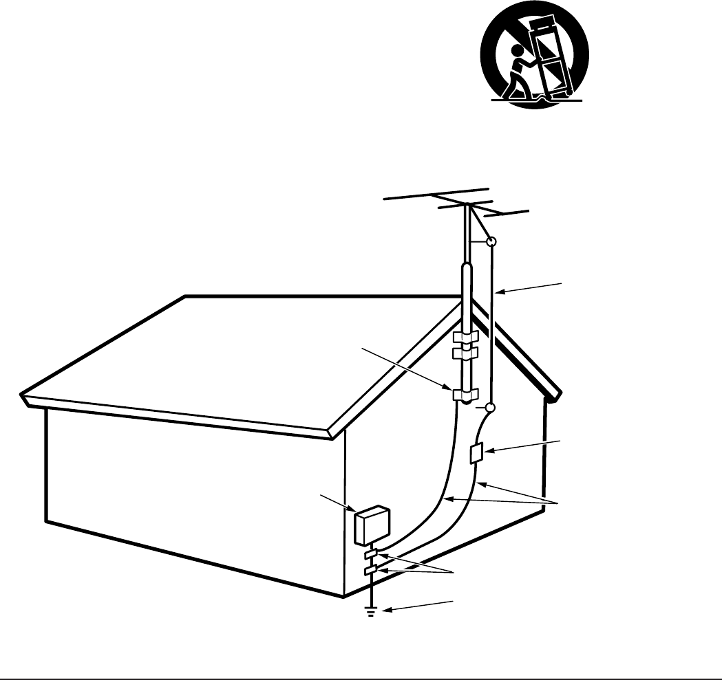
14. Outdoor Antenna Grounding-If an outside antenna or cable
system is connected to the video product, be sure the antenna or
cable system is grounded so as to provide some protection
against voltage surges and built up static charges. Section 810 of
the National Electrical Code, ANSI/NFPA No. 70-1984, provides
information with respect to proper grounding of the mast and
supporting structure, grounding of the lead-in wire to an antenna
discharge unit, size of grounding conductors, location of antenna-
discharge unit, connection to grounding electrodes, and
requirements for the grounding electrode. See Figure 1.
15. Lightning-For added protection for this video product receiver
during a lightning storm, or when it is left un-attended and unused
for long periods of time, unplug it from the wall outlet and
disconnect the antenna or cable system. This will prevent damage
to the video product due to lightning and power-line surges.
16. Power Lines-An outside antenna system should not be located in
the vicinity of overhead power lines or other electric light or power
circuits, or where it can fall into such power lines or circuits. When
installing an outside antenna system, extreme care should be
taken to keep from touching such power lines or circuits as contact
with them might be fatal.
17. Overloading-Do not overload wall outlets and extension cords as
this can result in a risk of fire or electric shock.
18. Object and Liquid Entry-Never push objects of any kind into this
video product through openings as they may touch dangerous
voltage points or short-out parts that could result in a fire or
electric shock. Never spill liquid of any kind on the video product.
ii
19. Servicing-Do not attempt to service this video product yourself
as opening or removing covers may expose you to dangerous
voltage or other hazards. Refer all servicing to qualified service
personnel.
20. Damage Requiring Service-Unplug this video product from the
wall outlet and refer servicing to qualified service personnel
under the following conditions:
a. When the power-supply cord or plug is damaged.
b. If liquid has been spilled, or objects have fallen into the video
product.
c. If the video product has been exposed to rain or water.
d. If the video product does not operate normally by following the
operating instructions. Adjust only those controls that are
covered by the operating instructions as an improper
adjustment of other controls may result in damage and will often
require extensive work by a qualified technician to restore the
video product to its normal operation.
e. If the video product has been dropped or the cabinet has been
damaged.
f. When the video product exhibits a distinct change in
performance-this indicates a need for service.
21. Replacement Parts-When replacement parts are required, be
sure the service technician has used replacement parts specified
by the manufacturer or have the same characteristics as the
original part. Unauthorized substitutions may result in fire, electric
shock or other hazards.
22. Safety Check-Upon completion of any service or repairs to this
video product, ask the service technician to perform safety checks
to determine that the video product is in proper operating
condition.
23. Carts and Stands-The appliance should be used only with a cart
or stand that is recommended by the manufacturer.
24. An appliance and cart combination should be moved with care.
Quick stops, excessive force, and uneven surfaces may cause the
appliance and cart combination to overturn.
FIGURE 1
EXAMPLE OF ANTENNA GROUNDING ACCORDING TO
NATIONAL ELECTRICAL CODE INSTRUCTIONS
CONTAINED IN ARTICLE 810 - “RADIO AND TELEVISION EQUIPMENT”
This Class B digital apparatus meets all requirements of the Canadian
Interference - Cansing Equipment Regulations.
Cet appareil numérique de la Classe B respecte toutes les exigences
du Règlement sur le matériel brouilleur du Canada.
NEC - NATIONAL ELECTRICAL CODE
ANTENNA
LEAD IN
WIRE
GROUND
CLAMP
ANTENNA
DISCHARGE UNIT
(NEC SECTION 810-20)
GROUNDING CONDUCTORS
(NEC SECTION 810-21)
ELECTRIC
SERVICE
EQUIPMENT
GROUND CLAMPS
POWER SERVICE GROUNDING
ELECTRODE SYSTEM
(NEC ART 250, PART H)
iii
AV SURROUND RECEIVER SR7200
UP
SURROUND
VOLUME
DOWN
DSS/VCR2 AUX
VCR1
DVD
TV CD
CDR/MD
TAPE
TUNER
MEMORY
TUNING/PRESET
MODE
F/P
CLEAR
NIGHT
ATT
DISPLAY OFF
SLEEP
S-DIRECT
DIMMER
MUTE
A/D7CH INPUT
POWER ON/STNDBY
PHONES
STANDBY
AUX INPUT
BSPEAKERSA
MULTI ROOM
MULTI ROOM
S-VIDEO VIDEO L AUDIO R
A
SLEEP
MUTE
ANALOG
DIGITAL
MLP PCM
RF AUTO LOCK CIRCLE SURROUND EX MPEG DIRECT MEMORY PRESET SW LFE
SRSCSLRTTAPTYAUTOTUNEDDTS SOUNDVIRTUAL
1 2 3 4 5 6 DIGITALDTS
THX RCLCTTPEONRDSSTEREOTAPE 2 MON
PRO LOGIC
VIDEO SET
B
DOLBY
(75
Ω
)
GND
AM
FM
AUDIO
FRONT
MONITOR
CENTER
REMOTE CONTROL
OUT
CENTER
SURR.
CENTER
SURR.
SPEAKER SYSTEMS
B
LR
LR
VIDEO
COMPONENT SPEAKER SYSTEMS
A
CENTERSURR.CENTER
SURROUND
FRONT
Y
rC
b
DVD
C
DSS
/
VCR2
r
bC
C
Y
rC
bC
Y
OUT
VCR1
OUT
VCR2
DSS
/
TOR
MONI
S
-
VIDEO
VIDEO
OUT
OUT
VCR2
DSS
/
OUT
VCR1
MONITOR
ROOM
MULTI
VCR2
DSS
/
TV
DVD
VCR1
IN
TV
VCR1
DVD
VCR2
DSS
/
IN
OUT
IN
TV
DVD
VCR1
VCR2
DSS
/
OUT
TAPE
TAPE
/
MD
CDR
CD
RL
IN
MULTI
REMOTE
VCR2
DSS
/
VCR1
OUT
RL
/
MD
CDR
ROOM
MULTI
OUT
RL
IN
/
OUT
DIGITAL
DIG.OUT OPT
DIG
-
1 IN
DIG
-
2 IN
DIG.OUT COAX
DIG
-
3 IN
DIG
-
4 IN
DIG
-
5 IN
FRONT
SURR.
CENTER
SURR.
FRONT
WOOFER
SUB
WOOFER
SUB
RL
RL
OUT
2
CTRL
OUT
1
CTRL
ANTENNA
SPEAKER IMPEDANCE
SPEAKER IMPEDANCE
FRONT A
FRONT A
OR
OR
B,
B,
CENTER,
CENTER,
SURROUND,
SURROUND,
SURR. BACK
SURR. BACK
: 6
: 6
-
-
16 OHMS
16 OHMS
FRONT A
FRONT A
AND
AND
B
B
: 12
: 12
-
-
16 OHMS
16 OHMS
OUT
PRE
INPUT
7CH
MEMO
CLEAR
GUIDE MUTE
ENT
ENT
CH
VOL
OK
1 23 4 5
6 7 8 0
9
CD DVD
CD-R/MD
DSS TV VCR
AMP
LD
TUNER
TAPE
AUX
AUTO DTS CS5.1 6.1
DSP 6-STEREO 2CH OSD SLEEP
ON OFF
ON / OFF
SOURCE
MACRO MODE
LEARNING REMOTE
CONTROL RC
7200SR
POWER
AC OUTLET
(120V 60Hz)
UNSWITCHED
120W 1A MAX
SWITCHED
120W 1A MAX
NIGHT
ATT
DISPLAY OFF
MULTI ROOM
A
SLEEP
MUTE
ANALOG
DIGITAL
AUTO CIRCLE SURROUND DIRECT MEMORY PRESET SW LFE
SRSCSLRTPTYAUTOTUNEDDTS SOUNDVIRTUALDIGITALDTS
RCLRDSSTEREO
PRO LOGIC
B
DOLBY
qw
!9 @0
t
ey
!3
.
,
m
n
b
v
c
x
z
⁄0
⁄1
⁄2
⁄3 ⁄4
⁄7
⁄6
⁄5
r
ui o !0!1 !2
!4 !8!7!6!5
Speaker system
Attenuate
Night mode
⁄8
Display off
a s d f g h j kl ¡0 ¡1 ¡2 ¡3
¡4 ¡5 ¡6 ¡7 ¡8 ¡9 ™0 ™1 ™2 ™3 ™4 ™5
Preset channel
Surround modeMulti room mode
Input indicator Memory
Direct mode
Tuned
FM stereo
RDS mode
Mute
Sleep timer
Auto tuning mode
Encoded channel status
iv
(75
Ω
)
GND
AM
FM
AUDIO
FRONT
MONITOR
CENTER
REMOTE CONTROL
OUT
CENTER
SURR.
CENTER
SURR.
SPEAKER SYSTEMS
B
LR
LR
VIDEO
COMPONENT SPEAKER SYSTEMS
A
CENTERSURR.CENTER
SURROUND
FRONT
Y
rC
b
DVD
C
DSS
/
VCR2
r
bC
C
Y
rC
bC
Y
OUT
VCR1
OUT
VCR2
DSS
/
TOR
MONI
S
-
VIDEO
VIDEO
OUT
OUT
VCR2
DSS
/
OUT
VCR1
MONITOR
ROOM
MULTI
VCR2
DSS
/
TV
DVD
VCR1
IN
TV
VCR1
DVD
VCR2
DSS
/
IN
OUT
IN
TV
DVD
VCR1
VCR2
DSS
/
OUT
TAPE
TAPE
/
MD
CDR
CD
RL
IN
MULTI
REMOTE
VCR2
DSS
/
VCR1
OUT
RL
/
MD
CDR
ROOM
MULTI
OUT
RL
IN
/
OUT
DIGITAL
DIG.OUT OPT
DIG
-
1 IN
DIG
-
2 IN
DIG.OUT COAX
DIG
-
3 IN
DIG
-
4 IN
DIG
-
5 IN
FRONT
SURR.
CENTER
SURR.
FRONT
WOOFER
SUB
WOOFER
SUB
RL
RL
OUT
2
CTRL
OUT
1
CTRL
ANTENNA
SPEAKER IMPEDANCESPEAKER IMPEDANCE
FRONT AFRONT A
OROR
B,B,
CENTER,CENTER,
SURROUND,SURROUND,
SURR. BACK : 6SURR. BACK : 6
--
16 OHMS16 OHMS
FRONT AFRONT A
ANDAND
B : 12B : 12
--
16 OHMS16 OHMS
AC OUTLET
(120V 60Hz)
UNSWITCHED
120W 1A MAX
SWITCHED
120W 1A MAX
OUT
PRE
INPUT
7CH
VIDEO
OUT AUDIO
OUT
AUX INPUT
VIDEOS-VIDEO L AUDIO R
(FRONT AUX CONNECTIONS)
L
R
VIDEO CAMERA
MONITOR TV
S-VIDEO
IN
VIDEO
IN
CVBS
LR
AUDIO
OUT VIDEO
OUT S-VIDEO
OUT
TV
LR
AUDIO
OUT
DIGITAL
OUT VIDEO
OUT S-VIDEO
OUT
DVD PLAYER
LR
AUDIO
OUT AUDIO
IN
LR
VIDEO
OUT IN S-VIDEO
OUT IN
DIGITAL
OUT
SATELLITE TUNER or VCR2
LR
AUDIO
OUT AUDIO
IN
LR
VIDEO
OUT IN S-VIDEO
OUT IN
VCR
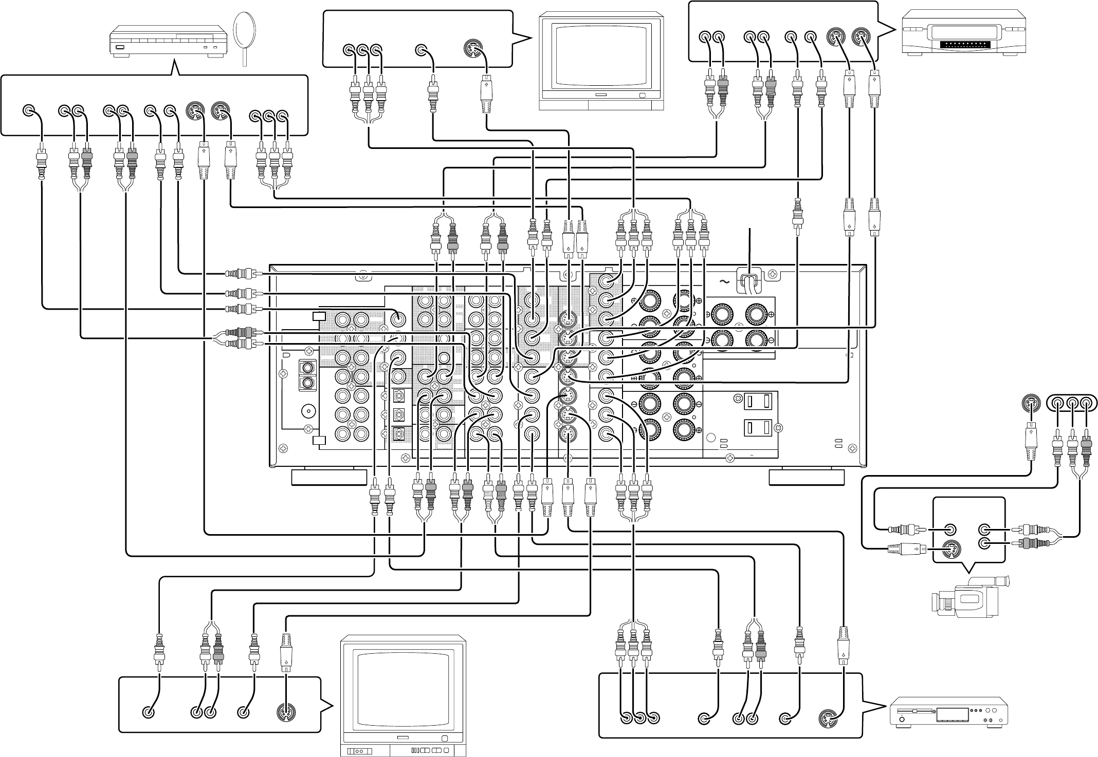
VIDEO SYSTEM CONNECTIONS FOR VIDEO COMPONENTS
To household
power outlet
COMPONENT
VIDEO
OUT
YCbCr
DIGITAL
OUT
COMPONENT
VIDEO
OUT
COMPONENT
VIDEO
IN
YCbCr
YCbCr
v
(75
Ω
)
GND
AM
FM
AUDIO
FRONT
MONITOR
CENTER
REMOTE CONTROL
OUT
CENTER
SURR.
CENTER
SURR.
SPEAKER SYSTEMS
B
LR
LR
VIDEO
COMPONENT SPEAKER SYSTEMS
A
CENTERSURR.CENTER
SURROUND
FRONT
Y
rC
b
DVD
C
DSS
/
VCR2
r
bC
C
Y
rC
bC
Y
OUT
VCR1
OUT
VCR2
DSS
/
TOR
MONI
S
-
VIDEO
VIDEO
OUT
OUT
VCR2
DSS
/
OUT
VCR1
MONITOR
ROOM
MULTI
VCR2
DSS
/
TV
DVD
VCR1
IN
TV
VCR1
DVD
VCR2
DSS
/
IN
OUT
IN
TV
DVD
VCR1
VCR2
DSS
/
OUT
TAPE
TAPE
/
MD
CDR
CD
RL
IN
MULTI
REMOTE
VCR2
DSS
/
VCR1
OUT
RL
/
MD
CDR
ROOM
MULTI
OUT
RL
IN
/
OUT
DIGITAL
DIG.OUT OPT
DIG
-
1 IN
DIG
-
2 IN
DIG.OUT COAX
DIG
-
3 IN
DIG
-
4 IN
DIG
-
5 IN
FRONT
SURR.
CENTER
SURR.
FRONT
WOOFER
SUB
WOOFER
SUB
RL
RL
OUT
2
CTRL
OUT
1
CTRL
ANTENNA
SPEAKER IMPEDANCESPEAKER IMPEDANCE
FRONT AFRONT A
OROR
B,B,
CENTER,CENTER,
SURROUND,SURROUND,
SURR. BACK : 6SURR. BACK : 6
--
16 OHMS16 OHMS
FRONT AFRONT A
ANDAND
B : 12B : 12
--
16 OHMS16 OHMS
AC OUTLET
(120V 60Hz)
UNSWITCHED
120W 1A MAX
SWITCHED
120W 1A MAX
OUT
PRE
INPUT
7CH
OUT IN
L
R
L
R
NORMAL
INPUT
INVERT
OUTPUT
CD PLAYER
SUBWOOFER
AMPLIFIER
(MA6100)
FM EXTERNAL
ANTENNA
FM FEEDER
ANTENNA
AM EXTERNAL ANTENNAAM LOOP ANTENNA
SURROUND
SPEAKER
CENTER
SPEAKER
SPEAKER SYSTEM A
FM antenna converter plug (attached)
When using the FM antenna
attach to this apparatus
(R)
(R)
(L)
(L)
OUTPUT
L
R
AUDIO SYSTEM CONNECTIONS FOR AUDIO COMPONENTS
MD PLAYER
TAPE DECK
DIGITAL
INPUT
DIGITAL
OUTPUT
SUB
WOOFER
CD RECORDER
OUT IN
L
R
L
R
To a component with REMOTE
(Marantz RC-5 D-BUS) jacks
Refer to "CONNECTION FOR A
SUBWOOFER" (Page 6)
DIGITAL
OUTPUT DIGITAL
INPUT
Assemble the AM loop antenna as
shown in the figure before use
LINE IN RC IN
MULTI ROOM SPEAKER
MAIN AMP
(For MULTI ROOM)
MULTI
ROOM
INPUT
(L) (R)
(L) (R)
L
R
IR RECEIVER
MULTI ROOM
MONITOR TV for MULTI ROOM
VIDEO
IN
SPEAKER SYSTEM B

1
ENGLISH
TABLE OF CONTENTS
INTRODUCTION .............................................................................................................................................................. 2
DESCRIPTION................................................................................................................................................................. 2
FEATURES ...................................................................................................................................................................... 2
FRONT PANEL FEATURES ............................................................................................................................................ 3
REAR PANEL CONNECTIONS ....................................................................................................................................... 4
REMOTE CONTROL UNIT RC7200SR........................................................................................................................... 7
OPERATION OF REMOTE CONTROL UNIT ........................................................................................................................................................... 7
SET-UP ............................................................................................................................................................................ 8
ON SCREEN DISPLAY MENU SYSTEM ................................................................................................................................................................. 8
OSD MAIN MENU .................................................................................................................................................................................................... 9
SYSTEM SETUP ...................................................................................................................................................................................................... 9
SPEAKERS SETUP ............................................................................................................................................................................................... 10
SURROUND MODE ............................................................................................................................................................................................... 11
CHANNEL LEVEL CONTROL ................................................................................................................................................................................ 11
MULTI ROOM SETUP ............................................................................................................................................................................................ 11
BASIC OPERATION ...................................................................................................................................................... 12
LISTENING TO THE TUNER .................................................................................................................................................................................. 12
PLAYBACK OPERATION ....................................................................................................................................................................................... 13
OTHER FUNCTIONS..................................................................................................................................................... 14
SETTING THE SLEEP TIMER ............................................................................................................................................................................... 14
TV AUTO ON/OFF FUNCTION .............................................................................................................................................................................. 14
MULTI ROOM SELECTOR ..................................................................................................................................................................................... 14
ON SCREEN DISPLAY INFOMATION .......................................................................................................................... 15
REMOTE CONTROL UNIT RC7200SR......................................................................................................................... 17
MAIN FEATURES & FUNCTIONS .......................................................................................................................................................................... 17
NAMES OF PARTS & FUNCTIONS ....................................................................................................................................................................... 17
BASIC OPERATION ............................................................................................................................................................................................... 19
OTHER FUNCTIONS ............................................................................................................................................................................................. 25
BATTERY LIFE ....................................................................................................................................................................................................... 25
NUMBER OF LEARNABLE CODES ...................................................................................................................................................................... 25
JOG DIAL COMMAND FUNCTIONS LISTING ...................................................................................................................................................... 26
SURROUND MODES .................................................................................................................................................... 27
TROUBLESHOOTING ................................................................................................................................................... 29

2
ENGLISH
INTRODUCTION
Thank you for purchasing the Marantz SR7200 DTS/Dolby Digital
Surround receiver.
This remarkable component has been engineered to provide you with
many years of home theater enjoyment.
Please take a few minutes to read this manual thoroughly before you
connect and operate the SR7200.
As there are a number of connection and configurations options, you
are encouraged to discuss your own particular home theater setup
with your Marantz A/V specialist dealer.
DESCRIPTION
DTS was introduced in 1994 to provide 5.1 channels of discrete digital
audio into home theater systems.
DTS brings you premium quality, discrete multi-channel digital sound
to both movies and music.
DTS is a multi-channel sound system designed to create full range
digital sound reproduction.
The no compromise DTS digital process sets the standard of quality
for cinema sound by delivering an exact copy of the studio master
recordings to neighborhood and home theaters.
Now, every moviegoer can hear the sound exactly as the moviemaker
intended.
DTS can be enjoyed in the home for either movies or music on DVD’s,
LD’s, and CD’s.
]
Dolby Digital lets you enjoy Digital TV, Digital Satellite as well as DVD, LD
software in digital surround, which is the next step above Dolby Pro Logic.
In Comparison with Dolby Pro Logic, Dolby Digital can provide
separate left surround and right surround channels, for more precise
localization of sound and a more convincing, realistic ambience.
And, with Dolby Digital all five main channels can be full ranged and a
subwoofer can be added to each channel, if desired.
By providing up to 5.1 channels of digital audio independently. Dolby
Digital lets you enjoy better sound quality and more powerful presence
than conventional Dolby Surround.
Pro Logic II, the next generation in Dolby Surround Pro Logic
technology, brings the excitement of surround sound to any existing
stereo mix, while making existing Dolby Surround mixes sound more
like discrete 5.1-channel surround sound. It works with CDs, VHS
tapes and TV shows, and MP3 files and radio broadcasts-converting
all of these source to surround sound, without the artifacts by other
matrix-decoding technologies.
Circle Surround is backward compatible, such that surround playback
is possible from any stereo or passive matrix-encoded material.
Five full-bandwidth, discrete channels of information can be extracted
from an enormous library of material not multi-channel encoded.
These sources include many of today’s DVDs and laser discs, as well
as most all video tape, VCD, Compact Disc, radio and television
broadcast material.
“Dolby”, “Pro Logic”, and the double-D symbol are trademarks of
Dolby Laboratories.
“DTS”, “ES” and “DTS Digital Surround” are trademarks of Digital
Theater Systems, Inc.
Circle Surround and the symbol are trademarks of SRS Labs, Inc.
Circle Surround technology is incorporated under license from SRS
Labs, Inc.
FEATURES
• Dolby Digital and DTS surround sound decoding, plus Dolby Pro
LogicII decoding, Circle Surround and a variety of additional
surround modes.
• 6.1 mode reproduces the original 6.1 channel soundfield by
extracting the surround back signal from surround left and surround
right channels.
• 96 kHz/ 24 bit decoding for highest possible fidelity and bandwidth,
and high-resolution playback of 96 kHz/ 24 bit PCM audio sources.
• 110 watts to each of the six main channels; the power amp section
features advanced, premium high-storage power supply capacitors,
and fully discrete output stages housed in cast aluminum heat sinks.
• 6.1 channel pre-amp outputs for connection to external components
such as a subwoofer and external power amplifiers.
• Seven-channel direct inputs accommodate future surround sound
formats or an external digital decoder.
• 5 Digital inputs, for connection to other sources, such as DVD, DSS,
CD, CD-R or MD.
• 2 Digital outputs for connection to CD-R or MD.
• High-quality AM /FM tuner with 30 station presets.
• Source Direct switch bypasses, tone controls and bass management
for purest audio quality.
• S-video and composite video switching .
• On- Screen- Display with both Composite and “S” video.
• Front panel A/V inputs, with S-video .
• Easy to use, on-screen menu.
• Multi-room capability offers independent control of a second room
audio and video system.
• Supplied with RC7200SR Programmable Learning Remote Control.

3
ENGLISH
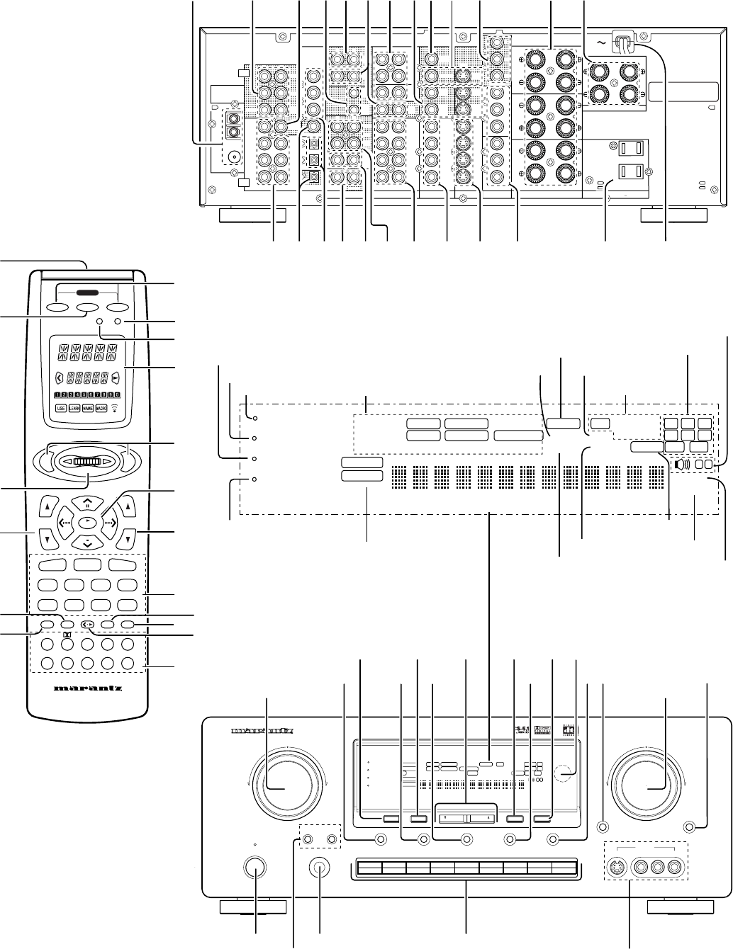
FRONT PANEL FEATURES (SEE
PAGE iii.)
qPOWER switch and STANDBY indicator
When this switch is pressed once, the unit turns ON and display
appears on the display panel. When pressed again, the unit turns OFF
and the STANDBY indicator lights.
When this unit is in the standby mode, pressing one of the FUNCTION
SELECTOR buttons also allows to turn the power on.
“When the STANDBY indicator lights up, the apparatus is NOT
disconnected from the AC supply mains.”
wPHONES jack for stereo headphones
Conventional dynamic headphones can be plugged in here.
Notes:
When using headphones, turn off the speakers system A and B
with SPEAKERS buttons. The surround mode is switched auto-
matically to STEREO.
eSURROUND MODE Selector knob
When this knob is turned, the surround mode is switched in the
following sequence.
Note:
Not all modes will be present if an analog input is selected.
rVOLUME control knob
Adjusts the overall sound level. Turning the control clockwise
increases the sound level.
tFUNCTION SELECTOR buttons (AUDIO/
VIDEO)
These buttons are used to select the sources.
The video function selector, such as TV, DVD , VCR1, DSS/VCR2,
and AUX, selects video and audio simultaneously.
Audio function sources such as CD, TAPE, CD-R/MD and TUNER
may be selected in conjunction with a Video source.
This feature (Sound Injection) combines a sound from one source with
a picture from another.
Choose the video source first, and then choose a different audio
source to activate this function.
y7CH INPUT button
Press this button to select the output of an external multi channel decoder.
uA/D (Analog/Digital) SELECTOR button
This is used to select between the analog and digital inputs.
Note:
This button is not used for an input source that is not connected to
a digital input.
iS. ( Source) DIRECT button
When this button is pressed, the tone control circuit is bypassed as
well as Bass Management.
Notes:
The surround mode is automatically switched to AUTO when the
source direct function is turned on.
Additionally, Speaker Configurations are fixed automatically as follow.
Front SPKR = Large
Center SPKR = Large
Surround SPKR = Large
Surround Center SPKR = Yes
Sub woofer = Yes
oSLEEP button
Set the sleep timer function with this button .
!0 DIMMER button
When this button is pressed once, the display is dimmed.
When this button is pressed twice, the display is turned off and
“DISPLAY OFF” indicator lights up.
Press this button again to turn the display ON again.
!1 MULTI (Multi Room) button
Press this button to switch the unit to multi room mode. “MULTI
ROOM” indicator lights up.
!2 MUTE button
Press this button to mute the output to the speakers. Press it again to
return to the previous volume level.
!3 CLEAR button
Press this button to cancel the station memory setting mode or preset
scan tuning.
!4 MEMORY button
Press this button to enter the tuner preset memory numbers and
station names.
!5 TUNING / PRESET UP and DOWN buttons
During reception of AM or FM, you can scan the other frequencies or
select another preset station pressing these buttons.
!6 FREQUENCY / PRESET button
During reception of AM or FM, you can change the function of the UP/
DOWN buttons for scanning frequencies or selecting preset stations
by pressing this button.
!7 FM MODE button
Press this button to select the auto stereo mode or mono mode when
the FM band is selected. The AUTO indicator lights in the auto stereo
mode.
!8 INFRARED SENSOR window
This window receives infrared signals from the remote control unit.
!9 SPEAKERS buttons
Press these buttons to select speakers systems A and/or B.
@0 AUX input jacks
These auxiliary video/audio input jacks accept the connection of a
camcorder, portable VCR, etc.
AUTO
DTS
DOLBY PL II
MOVIE
6CH STEREO MATRIXSTEREO
HALL
STADIUM
DOLBY
PRO LOGIC
DOLBY PL II
MUSIC MOVIE
CS 5.1
6.1CH
SURROUND
VIRTUAL

4
ENGLISH
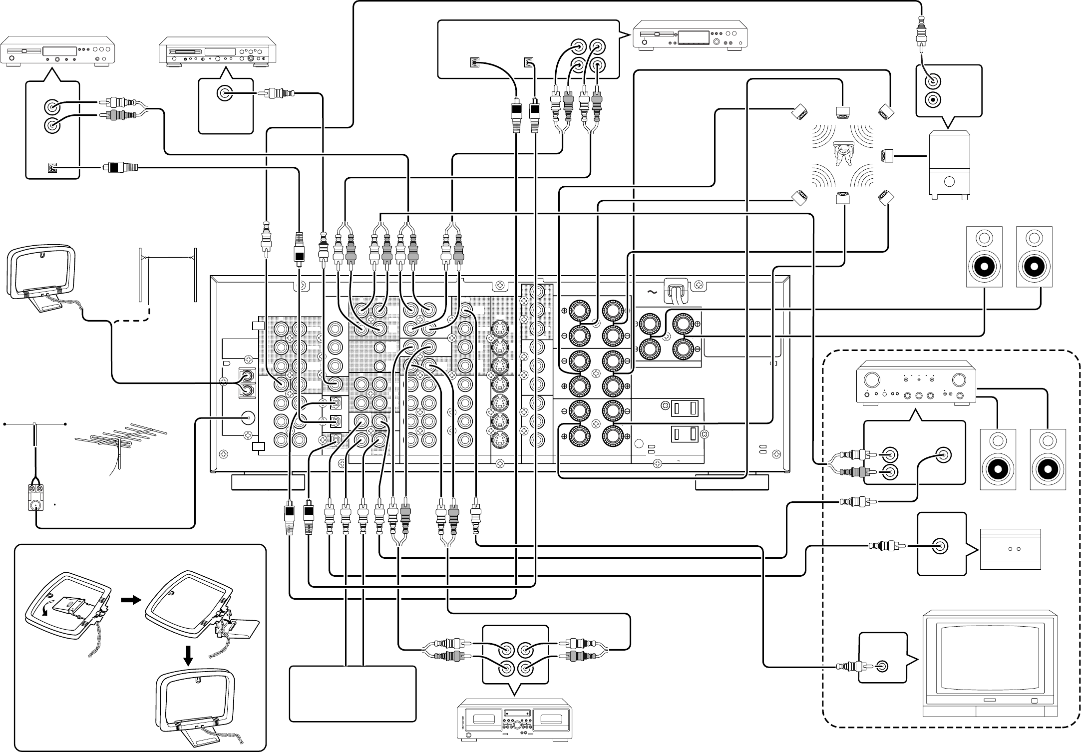
REAR PANEL CONNECTIONS
(SEE PAGE iii.)
All connections to the rear panel should be made with the entire
system powered off.
To avoid errors, it is advisable to connect one cable at a time between
the various components.
aFM antenna terminal (75 ohms)
Connect an external FM antenna with a coaxial cable, or a cable
network FM source.
AM antenna and ground terminals
Connect the supplied AM loop antenna. Use the terminals marked
“AM” and “GND”.
The supplied AM loop antenna will provide good AM reception in most
areas.
Position the loop antenna until you hear the best reception.
sPRE OUT jacks
Jacks for Front - L/R, Center,Surround and Surround center.
Use these jacks for connection to an external power amplifier.
dSUB WOOFER output jack
Connect to the input jack(s) of the power amplifier for subwoofer
channel or powered subwoofer.
fDC control output 1 & 2
Connect a device that needs to be triggered by DC under certain
conditions (screen, power strip, etc…) Use the system setup menu (3/
3) to determine the conditions by which these jacks will be active.
Note:
This output voltage is for (status) control only, It is not sufficient for
drive capability.
gMULTI OUT jacks (Audio)
Connect to the input jacks of the amplifier used to drive the speakers
in another room (Second zone).
hAnalog audio outputs for audio source
equipment
TAPE and CD-R/MD
Connect each output to the audio inputs (REC in) of your recording
equipment.
jAnalog audio inputs
CD, TAPE, and CD-R/MD
Connect the audio outputs of your source components to the input
jacks on the receiver.
kVideo outputs
VCR1, and DSS/VCR2
Connect each output to the video input (REC in) of your video
recording equipment.
lMULTI OUT jack (Video)
Connect to the input jack of the TV monitor in another room (Second
zone).
¡0
TV MONI. (VIDEO/S-VIDEO) output jacks
Connect the TV MONI jack to your TV’s video input (VIDEO IN) jack.
You can connect your video equipment with S-VIDEO jacks if
possible, or the composite VIDEO jacks.
You must use the same type of connection from your video player into
the receiver, and out of the receiver into your TV.
Both must be composite video or both must be S-Video. You cannot
convert a signal from one type to the other.
When you connect to S-video connections, there will be no signal
output from the composite video jacks.
¡1 COMPONENT VIDEO outputs
Connect to these outputs to the component video inputs of a video
projector or monitor. When a source connected to one of the two
component video inputs is selected the signal will be sent to these jacks.
¡2 SPEAKER SYSTEMS A terminals
FRONT Left & Right speakers output terminals
Connect to the front left & right speakers.
CENTER speaker output terminals
Connect to the center speaker.
SURROUND Left & Right speakers output terminals
Connect to the surround (rear) left & right speakers.
SURROUND Center speakers output terminals
Connect to the surround center speakers.
¡3 SPEAKER SYSTEMS B terminals
FRONT Left & Right speakers output terminals
Connect to the front left & right speakers.
Notes:
When you use the speaker systems A and B simultaneously, the
connected speakers which are impeadance 12 to 16 ohms must be
used.
¡4 7 CH INPUT jacks
Connect to the outputs of an external multichannel decoder.
¡5 DIGITAL outputs
Optical and Coaxial
Connect digital input of your digital recording equipment.
¡6 DIGITAL inputs
Dig.1,2 (Optical) and Dig. 3, 4, 5 (Coaxial)
Connect each input to the digital output of your source equipment.
Use the system setup menu to assign digital input to appropriate
source. (see page. 9)
Note :
The coaxial connections are not for AC-3 RF from the LD player, If
you want to decode this type of signal, an external demodulator
must be used.
¡7 REMOTE CONT. IN/OUT terminals
Connect to a Marantz component equipped with remote control (RC-
5) terminals.
¡8 MULTI ROOM REMOTE I/O terminals
IN : Connect to multi-room remote control device, available from
your Marantz dealer.
OUT : Connect to the Marantz component equipped with remote
control (RC-5) terminals in another room (Second zone).
¡9 Analog audio outputs for video source
equipment
VCR1, and DSS/VCR2
Connect each output to the audio inputs (REC in) of your video
recording equipment.
™0 Analog audio inputs for video source
equipment
TV, DVD, VCR1, and DSS/VCR2
Connect each input to the audio outputs of your video source
equipment.

5
ENGLISH
™1 Video inputs
Ex: TV, DVD, VCR1, and DSS/VCR2
Connect each input to the video outputs of your video source
equipment.
™2 S-video inputs
Ex: TV,DVD, VCR1,and DSS/VCR2
Connect each input to the S-video outputs of your video source
equipment.
™3 COMPONENT VIDEO inputs
Ex: DVD,and DSS/VCR2
Connect to the Y/CR/Cb component video outputs of each your video
product to these jacks.
™4 AC OUTLET
Connect the power cables of components such as a DVD and CD
player to these outlets. Both SWITCHED and UNSWITCHED outlets
are provided.
The one marked SWITCHED provides power only when the SR7200
is turned on and is useful for components which you use every time
you play your system.
The one marked UNSWITCHED is always live as long as the SR7200
is plugged into a live outlet.
A component connected here may be left on permanently, or may be
switched off with its own power switch.
Caution:
In order to avoid potential turn-off thumps, anything plugged in
here should be powered up BEFORE the SR7200 is turned on.
™5 Power cable
Connect to AC power outlet.
SR7200 can be powered by 120V AC only.
6
ENGLISH
-
IN
OUTPUT
INPUT
5-13VDC
+
INVERT
OUT
VIDEO/
EXT.CONT.IN
8 OHMS
REMOTE CONT.
SPEAKER SYSTEM
(75
Ω
)
GND
AM
FM
AUDIO
CENTER
REMOTE CONTROL
OUT
CENTER
SURR.
CENTER
SURR.
IN
TV
DVD
VCR1
VCR2
DSS
/
OUT
TAPE
TAPE
/
MD
CDR
CD
RL
IN
MULTI
REMOTE
VCR2
DSS
/
VCR1
OUT
RL
/
MD
CDR
ROOM
MULTI
OUT
RL
IN
/
OUT
DIGITAL
DIG.OUT OPT
DIG
-
1 IN
DIG
-
2 IN
DIG.OUT COAX
DIG
-
3 IN
DIG
-
4 IN
DIG
-
5 IN
FRONT
SURR.
CENTER
SURR.
FRONT
WOOFER
SUB
WOOFER
SUB
RL
RL
OUT
2
CTRL
OUT
1
CTRL
OUT
PRE
INPUT
7CH
ANTENNA
SPEAKER IMPEDANCE
FRONT A
OR
B,
CENTER,
SURROUND,
SURR. BACK : 6
-
16 OHMS
FRONT A
AND
B : 12
-
16 OHMS
REMOTE CONTROL
OUT
IN
REMOTE
MULTI
REMOTE
CONT.
OUT
IN
REMOTE
CONT.
OUT
IN
Other Marantz
Equipment (RC-5)
LINE IN
Powered subwoofer
Marantz MA6100
power amplifier
Subwoofer speaker
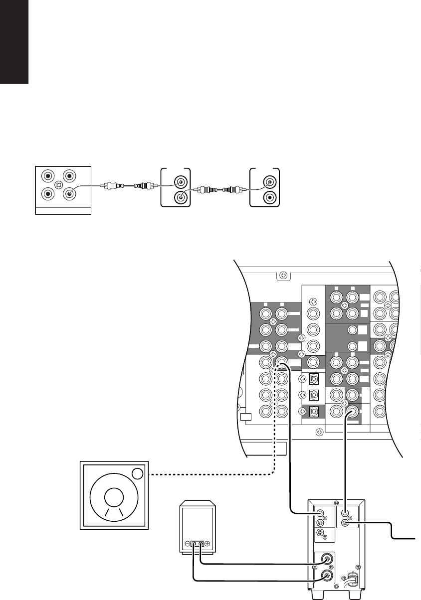
REMOTE CONTROL BUS CONNECTIONS
This unit is equipped with a remote control function.
By connecting this unit’s remote control jacks to a Marantz CD player
or tape deck equipped with remote control (RC-5) jacks, it allows
system remote control to operate.
Connect REMOTE CONTROL OUT jack of SR7200 to REMOTE
CONT. IN of other Marantz equipment, i.e. CD player or tape deck, by
using an RCA pin cable.
Note:
If a component equipped with remote control (RC-5) jacks has an
INT/EXT switch on the rear panel, set the switch to EXT when using
the system control function.
(Connection example)
SR7200 rear panel CD player rear panel Tape deck rear panel
Controlling the power ON/OFF of a power amplifier connected to
the SR7200 through Marantz remote control
1. Now the MA6100 can be turned ON / OFF in synchronism with the
power ON / OFF of the SR7200.
Notes:
nBe sure to connect the remote control bus before the procedure
above.
CONNECTION FOR A SUBWOOFER
Use this connection when using
a sub-woofer speaker.
You can also connect a powered
subwoofer.
7
ENGLISH
REMOTE CONTROL UNIT RC7200SR
This chapter describes the functions which need to control the
SR7200. See page 19 and following pages to refer other function of
the RC7200SR.
cPOWER ON and OFF
These two buttons are use for turning on or off SR7200.
bLCD
Used to display information about currently selected modes and
functions.
nJog Dial control
Rotate this dial to select commands displayed on the LCD for each
function. (See page 26)
Refer to follow.
Function
Jog Dial command
Note
AMP 1 A/D switches analog/digital input
2 ATT switches attenuator for analog input
3 NIGHT selects NIGHT mode for Dolby Digital
4 MR-ON turns multi-room mode on
5 MR-OF turns multi-room mode off
6 7-DIR activates 7-channel input
7 TRB+ increases treble
8 TRB- decreases treble
9 BAS+ increases bass
0 BAS- decreases bass
TUNER 1 FM FM band
2 AM AM band
3 LW Long Wave band
4 T-MOD mono/stereo mode selector
5 SCAN programmed preset channel scan
6 STM selects station mode
7 F-DIR inputs a frequency directly
8 PTY selects PTY function
9 DISP selects display function
0 DWR selects DSR wave range
The marked “⊗” commands are not used for SR7200.
mENT buttons
Press this button to enter the selected command by the Jog Dial.
,FUNCTION buttons
Press one of these buttons twice within 2 seconds to select the input
function of SR7200.
Press one of these buttons once to change the state of remote
commander.
.VOLUME up / down buttons
These buttons are used to raise and lower the SR7200’s volume level.
⁄0 CURSOR buttons
The cursor buttons can be used to navigate within on-screen menus of
SR7200.
⁄2 Channel up / down buttons
Used to controls the up/down function of tuner, or allows one to cycle
through the tuner presets.
⁄3 MUTE button
This button can be used to mute the sound temporarily.
⁄5 CLEAR button
This button is used to cancel certain memory or programming
operations.
⁄6 MEMO button
This button is used to enter the tuner preset memory numbers and
station names.
⁄7 TEN KEYPAD
They are useful for tuning a pre-set radio station and setting a station
name.
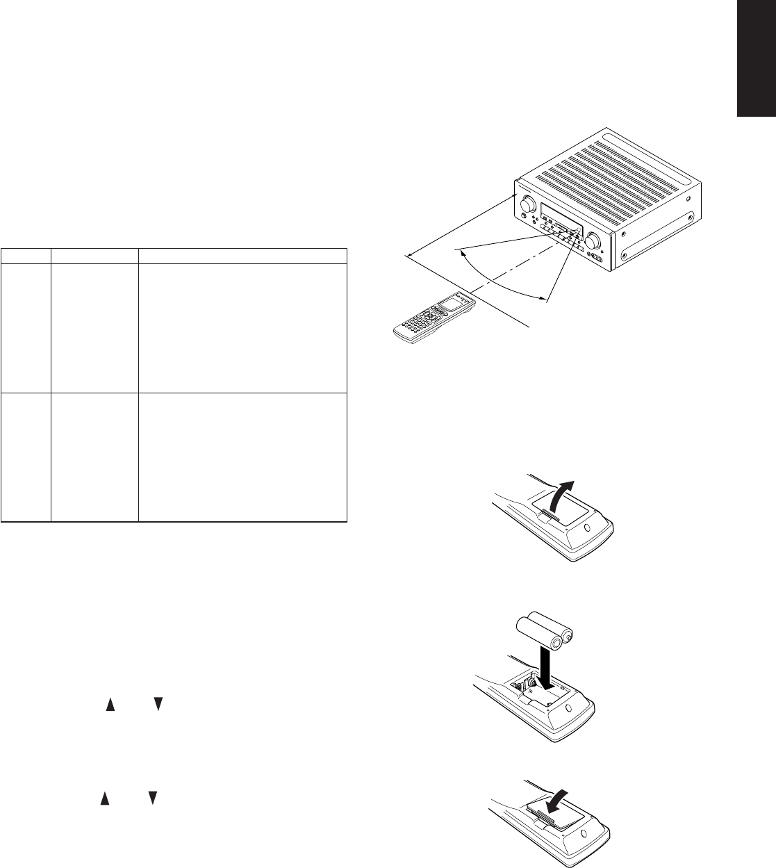
OPERATION OF REMOTE CONTROL UNIT
1. Remote control
The distance between the transmitter of the remote control unit and the
IR SENSOR of the SR7200 should be less than about 5 meters. If the
transmitter is pointed to a direction other than the IR SENSOR or if
there is an obstacle between them, remote control may not be possible.
Remote-controllable range
2. Loading batteries
The life of the batteries used with the remote control unit is about 4
months with normal use. Also be sure to replace batteries earlier when
you notice that they are getting weak.
(1) Remove the back cover.
(2) Insert the new batteries (AA type) with correct (+) and (–)
polarity.
(3) Close until it clicks.
Remote control unit (RC7200SR)
60°
SR7200
Approx. 5 m
⊗
⊗
⊗
8
ENGLISH
SET-UP
After all components are connected, initial setup must be performed.
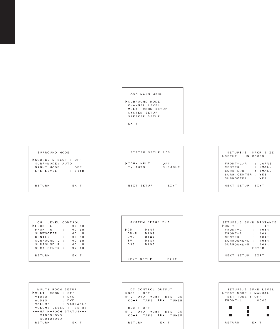
ON SCREEN DISPLAY MENU SYSTEM
The SR7200 incorporates an on-screen menu system, which makes
various operations possible by using the cursor (<, >, ^, v) and OK
buttons on the remote controller.
The settings made with these buttons are also shown in the on-screen
display.
SURROUND MODE SYSTEM SETUP 1/3
SYSTEM SETUP 2/3
SPEAKER SETUP 1/3 SPKR SIZE
SPEAKER SETUP 2/3 SPKR DISTANCE
SPEAKER SETUP 3/3 SPKR LEVEL
CHANNEL LEVEL CONTROL
MULTI ROOM SETUP
OSD MAIN MENU
SYSTEM SETUP 3/3
9
ENGLISH
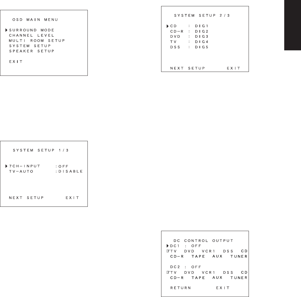
OSD MAIN MENU
1. Press the AMP button ,.
2. Press OK button ⁄0 to display the “MAIN MENU” of the on-screen
display menu.
Choose a desired item in the contents with ^ or v button, and
press the OK button to select.
Display will change to menu for each item.
SYSTEM SETUP
SYSTEM SETUP 1/3
7CH-INPUT : The 7 channel input of the SR7200 can be
selected to use a 7channel input. Select 7
channel use by < or > button.
TV AUTO : This product is equipped with a TV-auto ON/
OFF system, which automatically turns on or off
the power 1 second to 5 minutes after the TV
video input signal has been sent or has been
stopped.
Switch the TV AUTO ON/OFF function to enable
or disable with < or > button.
To use this function, connect the TV video input
to TV tuner’s video output.
NEXT SETUP/EXIT :If you desire to continue the next setup ,press
the OK button on NEXT-SETUP, if you desire to
exit from OSD menu system, press the OK
button on EXIT.
SYSTEM SETUP 2/3 (SELECTING THE DIGITAL INPUT)
Five digital inputs can be assigned for the desired source.
Use this menu to determine which source is connected to which input.
Example;
When the digital output of a DVD player is connected to Digital 4 (input
jack) of the SR7200;
1. Move the cursor on the line of the DVD with cursor buttons ^ or v.
2. Press the the cursor < or > button until “DIG4” is displayed.
3. Press the OK button to chose.
4. If you desire to continue the next setup, press the OK button on
NEXT-SETUP.
If you desire to exit from OSD menu system, press the OK button
on EXIT.
Notes:
The TUNER, VCR1, TAPE and AUX are assigned to the analog
input, and are prevented from selecting any digital input.
While the DTS-LD or DTS-CD is playing, this setup is not available,
this is to avoid noise being generated from the analog input. Stop
the LD or CD playback to setup.
The SR7200 does not switch from digital input to analog input or
vice versa automatically.
In the event that both digital and analog inputs are connected to
SR7200, if you desire to switch to an analog input temporarily, you
can switch by pressing the A/D button u.
SYSTEM SETUP 3/3 (DC CONTROL OUTPUT)
SR7200 has two DC control jacks, each one is selectable to link with
input functions for the main room or multi room.
You can select MAIN ROOM, MULTI ROOM or OFF for DC1 & DC2
independently by < or > button.
And then press OK button and move the cursor to select the linked
input function you desired by < or > button and press OK button to
chose.
10
ENGLISH
SPEAKERS SETUP
The home theater system you already have installed should function
provided that there are left, center and right front speakers, left and
right rear/surround speakers and a subwoofer. For best results we
recommend that all front speakers be of the same type, with identical
or similar driver units. This will deliver smooth pans across the front
sound stage as the action moves from side to side.
Your center channel speaker is very important as over 80 % of the
dialog from a typical motion picture emanates from the center channel.
It should possess similar sonic characteristics to the main speakers.
Surround channel speakers need not be identical to the front channel
speakers, but they should be of high quality.
The surround center speaker is useful for playback of Dolby Digital
Surround EX or DTS-ES. One of the benefits of both Dolby Digital
(AC-3) and DTS is that surround channels are discrete full range,
while they were frequency limited in earlier “Pro Logic’ type systems.
Bass effects are an important part of home theater. For optimal
enjoyment a subwoofer should be used as it is optimized for low
frequency reproduction. If you have full range front speakers,
however, they may be used in place of a subwoofer with proper setting
of the switches in the menu system.
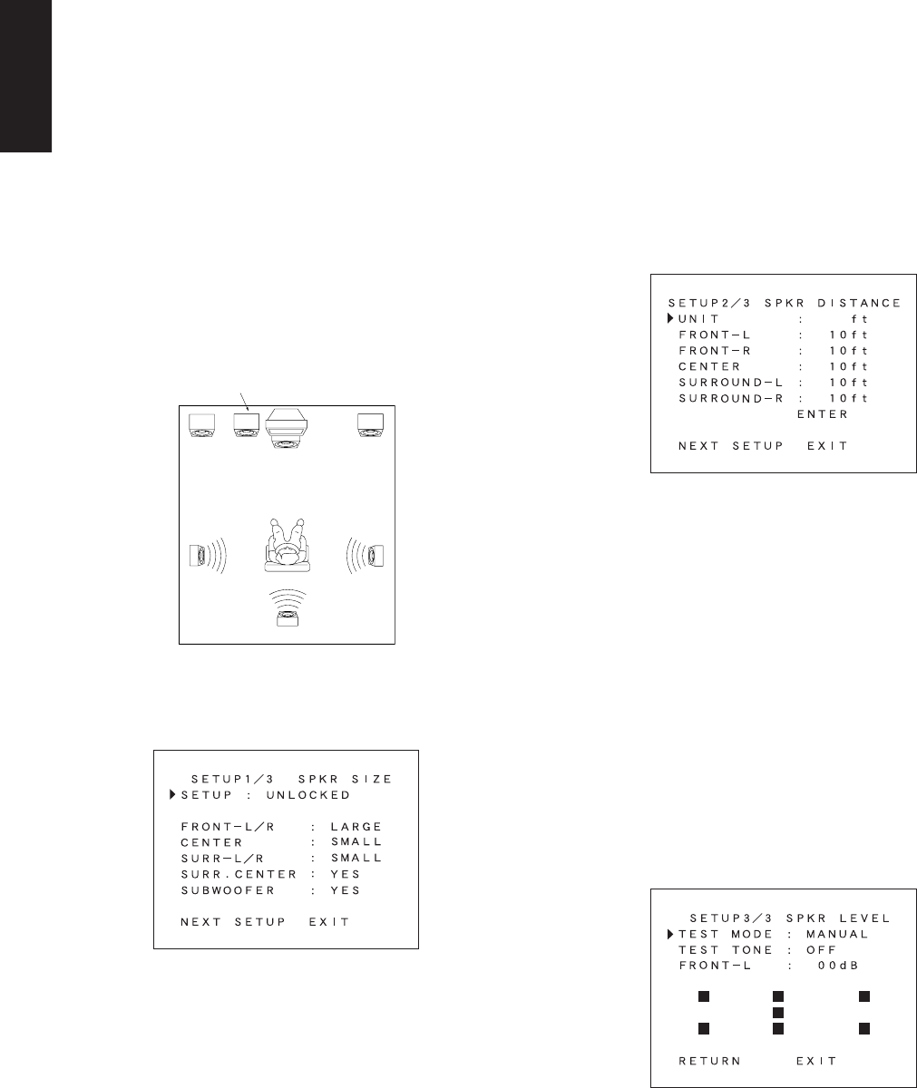
If possible, mount the surround speakers on the walls to the sides of
the viewing area, 2-3 feet above seated viewers, firing straight across
at each other.
SPKR SETUP 1/3 (SPKR SIZE)
SETUP: Select “LOCKED” with < or > button in order to lock the
contents of the SPKR SET UP MENU.
Then, when you want to change the contents of this setup,
select “UNLOCKED”.
SPKR SIZE
This menu enters the information about which type of speakers will be
used for each channel.
In turn, these settings will determine which speakers receive low
frequency information.
For the purpose of establishing proper bass reproduction, use the
LARGE settings if the speaker being used at any position is a
traditional full-range loudspeaker that is capable of reproducing sound
below 100 Hz and you are not using a subwoofer.
Use the SMALL setting for smaller, frequency-limited speakers that are not
able to reproduce sounds below 100Hz and you are using a subwoofer.
Low frequencies will be diverted from the speaker to the subwoofer.
Note that when “small” speakers are used it is advisable to install a
separate subwoofer, especially if you wish to appreciate the full
impact of a good home theater soundtrack.
If the Surround speakers or Center speaker will not be used, set
NONE for each speaker. The NONE setting will send the audio for the
channel to other speakers.
FRONT -L/R : Select the type of front speakers with < or > button.
CENTER : Select the type of center speaker with < or > button.
SURR-L/R : Select the type of surround speakers with < or > button.
SURR.CENTER : Select the surround center speaker YES or NO with
< or > button.
SUBWOOFER: Select the subwoofer speaker YES or NO with < or
> button.
Notes:
The SUBWOOFER cannot be set to NO when the front speakers
are set to SMALL.
This speaker size setup is not effective when the SOURCE-
DIRECT or 7CH. Input is selected.
SPKR SETUP 2/3 (SPKR DISTANCE)
Use this parameter to specify the distance of the speaker’s position
from the listener.
The delay time is automatically set according to these distances.
UNITS:You can select Meters or Feet.
If you select “ft”, the setting parameter will change in 1 foot
steps.
If you select “m”, it will change in 0.3 meter steps.
Select speaker with ^ or v button, and input each speaker’s
distance with < or > button.
When the input for each speaker’s distance has been finished,
move the cursor to ENTER and press the OK button.
NOTES :
If your selection(s) are out of range, the distance cannot be stored.
Placement beyond that distance is beyond the range of the
automatic time delay feature.
The delay feature does not function in the SOURCE-DIRECT ,7
CH-Input modes and decoding of 96 kHz sources.
SPKR SETUP 3/3 (SPKR LEVEL)
SPKR LEVEL
TEST MODE: Selects the mode for generating the test tone.
If you select AUTO, the test tone will be cycled through
in a circular pattern which is Left → Center → Right →
Surround Right → Surround Center → Surround Left →
Subwoofer → Left → ... 3 seconds for each channel.
If you select MANUAL, press the OK button to select the
test tone channels after the “TEST TONE ON”.
TEST TONE: Press the < or >button, ON is indicated and the test
tone starts from the front L-CH speaker.
Press the < or > button again on this item. OFF is
indicated and the output of the test tone will stop.
Channel: Adjust the level of test tone for each channel with the < or
> buttons of the RC7200SR. The current volume level is
shown at the center of the display.
SUB WOOFER
LEFT CENTER RIGHT
SURROUND-L SURROUND-R
SURROUND CENTER
11
ENGLISH
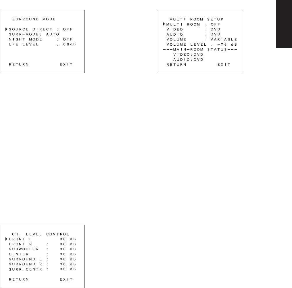
SURROUND MODE
SOURCE DIRECT : Switch the source direct ON or OFF with < or >
button. This bypasses the surround processing
and crossover for the main speakers (front left
and right will be full range and the subwoofer will
be ON)
Note: Surround mode cannot be changed in
Source Direct mode.
SURR-MODE : Select the surround mode with < or > button.
NIGHT MODE : Switch the NIGHT MODE ON or OFF with < or >
button.
Selecting the Night Mode ON is effective in Dolby
Digital only, and it compresses the dynamic
range.
This softens loud passages such as sudden
explosions, to help prevent disturbing others late
at night.
LFE LEVEL : Select the output level of the LFE signal included
in the Dolby Digital signal or the DTS signal.
Select 0dB, -10 dB or OFF with < or > button.
The level is ordinarily set to 0 dB. When use DTS
music source, LFE level is set to -10 dB.
CHANNEL LEVEL CONTROL
Desired channels can be selected by pressing ^ or v button.
Each channel level will be adjusted by pressing < or > button.
Only the usable channels which are determined depending on the
SURROUND mode, and SPEAKER SETTING are displayed.
MULTI ROOM SETUP
MULTI ROOM : To switch on the Multi-room output.
VIDEO : Select the video source of the Multi-room
output.
AUDIO : Select the audio source of the Multi-room
output.
VOLUME : Select whether the Multi-room output level
is variable or fixed.
VOLUME LEVEL : Adjust the Multi-room output level.
MAIN ROOM STATUS : Selected input source in the main room will
be displayed.
Notes:
If “VOLUME” is set to “FIXED”, the multi-room output level cannot
be adjusted.
You cannot transmit a digital signal using the multi-room function.
Any source component that is desired to be operated in the second
zone needs to have the analog outputs connected to receiver.

12
ENGLISH
BASIC OPERATION
LISTENING TO THE TUNER
MANUAL TUNING
1. To select the tuner as the source, press the TUNER button t on
the front panel or press the TUNER button , on the remote
control unit.
2. Press the TUNER button t on the front panel or press the
TUNER button , on the remote control unit to select the desired
frequency band if required.
3. Press the F/P button !6 on the front panel to display the frequency.
4. Press the TUNING/PRESET or button !5 on the front panel or
press the ^, v button ⁄0 on the remote control unit.
5. If FM is selected, press the MODE button !7 on the front panel or
select T-MOD by the Jog Dial n and press the ENT button m in
the TUNER mode on the remote controller.
(FM) MODE BUTTON OPERATION
When “AUTO” indicator is on in the display, FM stations that broadcast
in stereo will be received in stereo and the “STEREO” indicator lights.
When “AUTO” indicator is off, all the FM stations will be received in
mono regardless of whether or not they are broadcasting in stereo.
AUTO TUNING
1. Press the F/P button !6 on the front panel to display the frequency.
2. Press the TUNING/PRESET or button !5 on the front panel
for more than 1 second to start the Auto tuning function.
AUTO TUNING (USING THE REMOTE CONTROL UNIT)
Press ^, v button ⁄0 for more than 1 second to start the Auto tuning
function.
PRESET TUNING
With this unit you can preset up to 30 FM/AM stations in any order. For
each station, you can memorize the frequency and reception mode if
desired.
1-a. Manual Presetting
1. Refer to the “MANUAL TUNING” or “AUTO TUNING” section
above to tune in a desired station.
2. Press the MEMORY button !4. “MEMORY” indicator starts blinking
on the display.
While “MEMORY” is still blinking (approx. 5 seconds), select the
preset number by pressing the TUNING/PRESET or button !5
then press the MEMORY button !4 again.
3. When a number has been properly input, “MEMORY” indicator
stops blinking and goes out.
The station is now stored in the specified preset memory location.
1-b. Manual Presetting (Using the remote unit)
1. Tune in a desired station.
2. Press the MEMO button ⁄6.
3. Enter the desired preset number with ten keypad ⁄7.
4. Then, press MEMO button ⁄6 again to store.
2. Auto Presetting
This function automatically scans the FM and AM band and enters all
stations with sufficient signal strength into the memory.
1. Press and hold down the MEMORY button !4 and TUNER button
t simultaneously for 3 seconds or more.
2. “MEMORY“ will blink on the display.
3. Each time the tuner finds a station, the scanning will pause and
memory. Auto presetting will starts.
4. Operation stops automatically when all 30 preset memory
positions are filled or when auto scanning attains the highest end
of all bands.
To stop the auto preset function at anytime, press the CLEAR
button !3.
3. Recalling a Preset Station
1. Press the F/P button !6 to change the display to preset.
2. Select the desired preset station by pressing TUNING/PRESET
or button !5 on the front panel or press CH or CH button ⁄2
on the remote.
Note:
To directly access the preset stations using the numeric keypad,
select the desired preset station by entering one or two digits using
the numeric keypad ⁄7.
To return to the Manual Tuning mode, press the F/P button !6.
4. Preset Scan Tuning (Using the remote control unit)
1. Select the SCAN by the Jog Dial n and press the ENT button m
in the TUNER mode on the remote controller. (The preset station
with the smallest preset number is recalled first. If no stations have
been preset, “NO PRESET” shows in the display and the unit
returns to the previous mode.)
2. Preset stations are recalled in sequence (CH-1 → CH-2, etc.) for 5
seconds each. Preset numbers that do not contain stations are
skipped.
3. You can fast forward the preset stations by pressing the CH
button continuously.
When the desired preset station is received, cancel the preset scan
operation by pressing the CH button or the CLEAR button ⁄5.
5. Clearing Preset Stations
You can remove preset stations from memory using the following
procedure.
1. Recall the preset number to be cleared with the method described
in “Recalling” a preset station.
2. Press the CLEAR button !3 on the front panel or CLEAR button
⁄5 on the remote control unit for 3 seconds or more.
“CLEAR” appears on the display to indicate that the specified
preset number has been cleared.
6. Frequency Direct Call
1. Select F-DIR by the Jog Dial n and press the ENT button m in
the TUNER mode on the remote controller.
2. Display shows “FM– – –.––MHz” (at FM mode).
3. Input your desired frequency with tenkeypad buttons on the
remote controller.
Eg) 98.1 MHz
Press 9, 8, 1 and 0
4. Press the ENT button m again.

13
ENGLISH
STATION NAME PRESET (on PRESET display mode)
The station name preset function allows the name of each preset
channel to be entered using alphanumeric characters. The Station
Name button is valid only in the tuner mode. Before station name
preset operation, store stations with the preset memory operation.
1. Press the MEMORY button !4 on the front panel or MEMO button
⁄6 on the remote for more than 3 seconds.
2. The left most column of the station name indicator flashes,
indicating the character entry ready status.
[Operation (Using the SR7200)]
3. When you press the TUNING/PRESET or buttons !5 is
turned, alphabetic and numeric characters will be displayed in the
following order:
A → B → C ...Z → 1 → 2 → 3..... 0 → – → + → / → (Blank) → A
UP →
← DOWN
4. After selecting the first character to be entered, press the
MEMORY button !4. The entry in this column is fixed and the next
column starts to flash. Fill the next column and press the
MEMORY button !4 for more than 1 second to confirm the entry.
[Operation (Using the remote unit)]
First, press the TUNER button on the remote control unit.
(This operation is not necessary if the remote control unit has
already been operated in the TUNER mode.)
3. Enter the character using the ten keypad ⁄7. For example, to
enter “A”:
1) Press the “1” button. “A” appears on the display column.
2) Every time the 1 button is pressed, the displayed character
changes in the order: A → B → C → 1 → A...
Pressing buttons other than the “1” button cause different
characters to be displayed in a similar way, so that other
alphanumeric characters can be entered. To enter a blank or
space, press the “9” button.
4. When the desired character is displayed, press the MEMO button
⁄6 to confirm the entry in this column and move to the next
column. After having filled all of the 8 columns, press the MEMO
button ⁄6, for more than 1 second to confirm the entry.
PLAYBACK OPERATION
NORMAL PLAYBACK
1. Press the POWER ON button on the remote.
2. Press the FUNCTION SELECTOR button t on the front panel or
press the FUNCTION button , on the remote unit to select an
input source.
3. Turn the SURROUND MODE SELECTOR knob e on the front
panel or Surround mode buttons ⁄7 in the AMP MODE on the
remote unit to select the desired surround mode.
4. Adjust the volume level using the VOLUME knob r on the front
panel or press the VOL / button . on the remote. If
necessary, adjust the tone, select the TRB+, TRB– and BAS+,
BAS– by the Jog Dial n and press ENT button m in the AMP
MODE on the remote unit.
Notes:
•In case of remote control operation, press one of the function
buttons twice within 2 seconds to select the function.
•Tone control is available for following surround modes.
AUTO (except 96 kHz), STEREO, DOLBY PRO LOGIC and DTS.
LISTENING TO A DIFFERENT AUDIO SOURCE WHILE
WATCHING A VIDEO SOURCE (Using the remote control
unit)
1. Select one of the following video sources
TV, DVD, VCR1, DSS/VCR2 or AUX.
2. Next, select one of the following audio sources
FM, AM, CD, TAPE, or CD-R/MD.
14
ENGLISH
OTHER FUNCTIONS
SETTING THE SLEEP TIMER
Set the sleep timer while the power is turned on.
1. Turn the power ON and press the SLEEP button o.
2. Press the SLEEP button o the number of times to set the desired
sleep time in minutes.
Each press of the SLEEP button o or changes the display in the
following order:
The unit will shut off in the number of minutes indicated.
* While the sleep timer is activated, the remaining time can be
displayed for approximately 2 seconds by pressing the SLEEP
button o.
* To cancel the sleep timer, press the SLEEP button o and then
press the CLEAR button !3.
TV AUTO ON/OFF FUNCTION
This function allows the component connected to the TV IN jack to
control the power (ON/OFF) to the SR7200.
AUTO POWER ON
1. Be sure TV auto mode is enable. (Refer page 9 : System Setup 1/3)
2. Connect your TV TUNER (etc) to the TV IN terminal.
Be sure to connect the video input.
3. Turn OFF the power to the TV TUNER and the SR7200 will be in
standby mode.
4. Turn ON the TV TUNER and tune in a receivable station.
5. When the station is received, the SR7200 turns ON and TV is
selected automatically.
AUTO POWER OFF
1. In the above situation, turn the TV TUNER OFF or select a
channel that does not contain any broadcast.
2. The SR7200 switches to STANDBY after approximately 5
minutes.
Note:
AUTO POWER OFF is canceled if the FUNCTION SELECTOR
button t is set to a source other than TV. The function reactivates
when TV is selected again.
Caution:
Some TV broadcasts may cause the TV AUTO FUNCTION to be
turned enable. To set this function to ENABLE/DISABLE, refer to
the SETUP MENU.
10 20 30
(OFF) 90 60
MULTI ROOM SELECTOR
The Multi Room Selector is a function which allows you to listen to the
same or a different source in a room other than the room in which the
SR7200 is located. To use this function, a multi room remote unit and
remote control signal receiver available from your Marantz dealer are
necessary. The operations possible with the multi room function are
explained briefly below. For details, refer to the instruction manual
supplied with the multi room remote control unit and receiver.
MULTI ROOM SELECTOR OPERATION
1. Press the MULTI ROOM button !1. The unit enters multi room
mode and the display indicates “SEL SOURCE” and flashes the
“MULTI ROOM” indicator for approx. 5 seconds. In this time, you
can select the input source by pressing the FUNCTION
SELECTOR button t.
2. Then, the display indicates “M/VOL xx dB”. At this time, you can
set the volume level of the multi room by turning the volume
control knob.
3. Then, the display indicates “M/SLEEP OFF” and you can set
sleep timer for multi room by pressing by the SLEEP button o
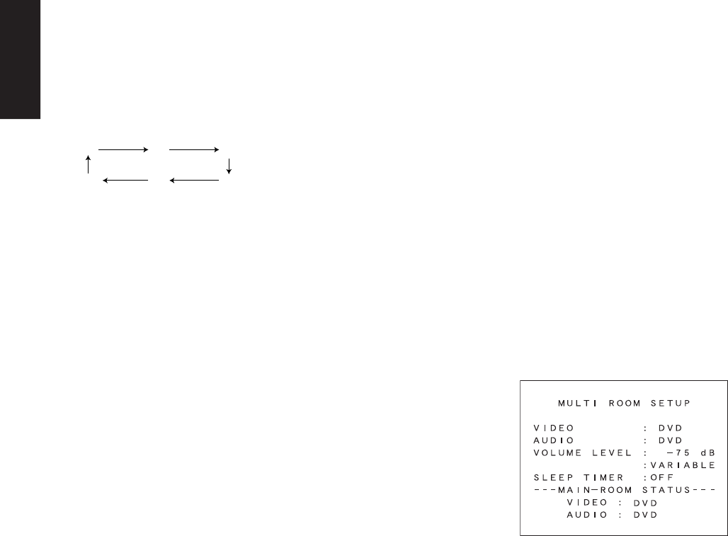
MULTI ROOM SELECTOR OPERATION (USING THE MULTI
ROOM REMOTE CONTROL UNIT)
1. If Video output for multi room is connected to the TV in your
second zone, the on screen display for this video signal will be
shown as follow.
2. Press the MULTI ROOM button !1, the POWER ON button, or
select the desired source on multi room remote control unit from
the MULTI ROOM. Any of these operations will put the SR7200
into multi room mode and “MULTI ROOM” indicator will light and
OSD system for the TV in the multi room will be shown.
3. Press the VOL.UP or VOL.DOWN button on the multi room
remote control unit to set the desired sound volume.
4. In multi room mode, the multi room remote control unit can be
used in the multi room to operate the following functions.
You can select a tuner preset channel and tuning up or down, and
direct selection. And you can control the CD player, DVD player
VCR and tape deck connected to the SR7200.
5. Additionally, SLEEP timer function for multi room is available from
second zone, by the same way as setting the sleep timer for main
room.
6. The status of the main room setting can be monitored from the
second zone with the OSD.
Caution:
If the main room and the secondary room are listening to the same
source, the main room will have priority over controlling that
source. For example, you cannot change the frequency or preset of
the Tuner from a remote location if the main room is also listening
to that source.
15
ENGLISH
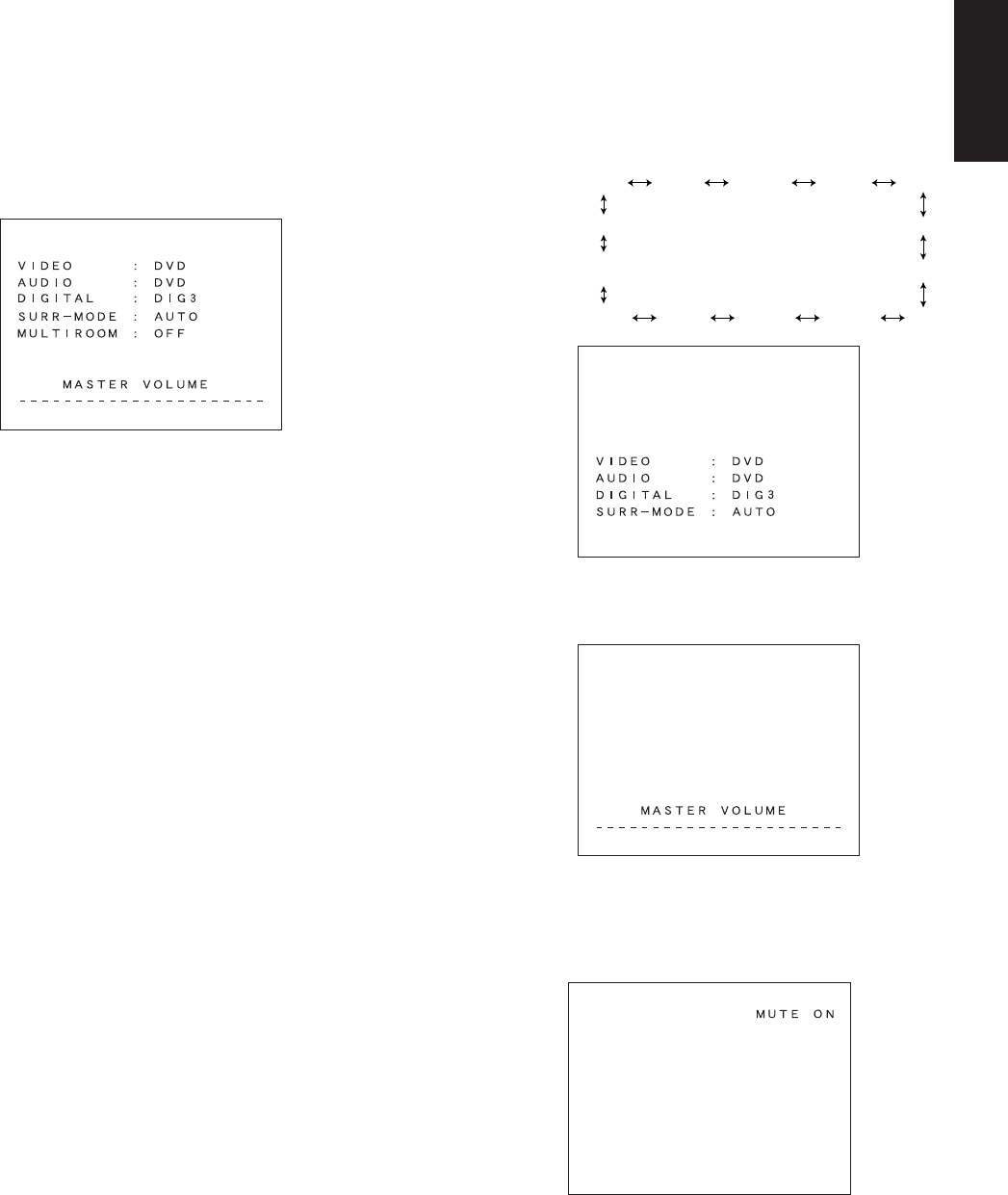
ON SCREEN DISPLAY INFOMATION
The on-screen display, which can be activated by the Main unit or
remote, appears on the TV screen to show the current setting status of
the SR7200.
1. GENERAL INFORMATION
When the OSD button ⁄7 is pressed, the current setting are displayed
on the TV monitor.
This display disappears automatically in about 5 seconds after the
button is pressed.
q VIDEO SOURCE:
Displays the current video source being selected with the function selector
TV, DVD, VCR1, DSS or AUX.
w AUDIO SOURCE:
Displays the current audio source being selected with the function selector
FM, AM, CD, TAPE, CD-R, TV, DVD, VCR1, DSS or AUX.
e DIGITAL INPUT:
Displays the digital input that you are using
DIG-1, DIG-2, DIG-3, DIG-4 or DIG-5.
r SURROUND MODE:
Displays the current surround mode
AUTO, STEREO, 6CH STEREO, VIRTUAL, MATRIX, STADIUM,
HALL, MOVIE, CS5.1, 6.1 CH SURR, PLO LOGIC, PLII MUSIC,
PLII MOVIE, DTS
t MULTI ROOM
Displays the current status of the Multi Room function, ON or OFF.
y MASTER VOLUME
Displays the current volume level.
The volume level is higher at the right of the display.
Note:
The On-Screen Display signals for the main room can be output
from the TV MONI composite video (RCA) output and the TV
MONI, S-Video and TV MONI component video output jacks.
With some video equipment or software, the On-Screen Display
characters may be distorted due to noise or tracking adjustment
error.
2. FUCTION SELECT & SURROUND MODE
When a function selector button or surround mode button is pressed
VIDEO: Displays the current video source. When TV, DSS,
DVD, VCR1 or AUX is selected with the function
selector, both AUDIO and VIDEO shows the same
name.
AUDIO: Displays the current analog audio input source.
DIGITAL: Displays the current digital input source.
SURR-MODE: Displays the current Surround mode as follows;
3. MASTER VOLUME CONTROL
Displayed when the MASTER volume is varied or a button of the
remote control unit is pressed.
4. MUTE
When the MUTE button !2/⁄3 is pressed, “MUTE ON” will be shown on
screen.
Pressing MUTE button !2/⁄3 again will show “MUTE OFF” on screen,
and return to the previous volume level.
AUTO
DTS
DOLBY PL II
MOVIE
6CH STEREO MATRIXSTEREO
HALL
STADIUM
DOLBY
PRO LOGIC
DOLBY PL II
MUSIC MOVIE
CS 5.1
6.1CH
SURROUND
VIRTUAL

16
ENGLISH
5.SLEEP TIMER
When the SLEEP button o is pressed, the setting on or off and the
remaining time of the sleep timer function are displayed.
You can change the mode between on, off and the amount of time to
elapse before the unit will shut itself off by cycling the SLEEP button o.
6. OSD OFF
When OSD button ⁄7 is pressed, OSD system will be bypassed after 3
seconds.
Then there is no indication on the TV display.
Press the OSD button ⁄7 again to activate the OSD.
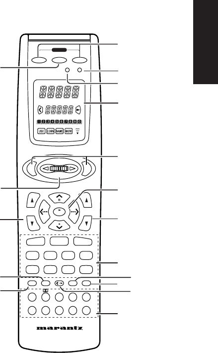
17
ENGLISH
REMOTE CONTROL UNIT RC7200SR
MAIN FEATURES & FUNCTIONS
• PROGRAMMABLE LEARNING FUNCTION
Can easily be programmed to learn the codes for almost any other
infrared-based remote, allowing the remote control functions for many
different components to be consolidated conveniently in a single unit.
• PRESET CODES
Function buttons already contain preset codes (using the RC-5/RC-6
remote control language) for other remote-controllable Marantz audio-
visual component.
• LUMINOUS BUTTONS
The remote controller uses luminous buttons which store light allowing
it to be used even in the darkened.
• LARGE, EASY-TO-READ DISPLAY
Large LCD (liquid crystal display) messages and other information at a
glance.
• JOG DIAL
The function selected by Jog Dial (displayed on the LCD) can be
operated directly by the enter button.
.
• MACRO CAPABILITY
Macro function allows the remote controller to be programmed to
execute complex strings of multiple commands using a single
keystroke.
• NAME ASSIGNMENT
Allows one to change the (displayed via the LCD) name for a function
button.
NAMES OF PARTS & FUNCTIONS
Names of Buttons & Functions
zMODE button
Used to change the operation mode of the remote controller. Pressing
this button cycles the remote controller through USE → LEARN →
NAME → USE, with the currently selected mode displayed on the
LCD.
xMACRO button
Used to switch the remote controller in and out of the MACRO mode,
which is used to program complex operational sequences (macros),
with the currently selected mode displayed on the LCD.
cPower ON and OFF buttons
Used to turn the main system component (usually a preamplifier or
receiver) ON and OFF.
vSource ON/OFF button
Used to turn specific sources (such as DVD players, etc.) ON and OFF
independently from the rest of the system.
bLCD
Used to display information about currently selected modes and
functions.
nJog Dial
Used to select the operation content for each source. 10 types of
direct operation are possible for each of the 11 functions including
DVD, TV, AMP, etc. After selecting the desired function, press either
of the ENT button m to transmit the signal.
MEMO
CLEAR
GUIDE MUTE
ENT
ENT
CH
VOL
OK
1 23 4 5
6 7 8 0
9
CD DVD
CD-R/MD
DSS TV VCR
AMP
LD
TUNER
TAPE
AUX
AUTO DTS CS5.1 6.1
DSP 6-STEREO 2CH OSD SLEEP
ON OFF
ON / OFF
SOURCE
MACRO MODE
LEARNING REMOTE
CONTROL RC
7200SR
POWER
.
,
m
n
b
v
c
x
z
⁄0
⁄1
⁄2
⁄3 ⁄4
⁄7
⁄6
⁄5
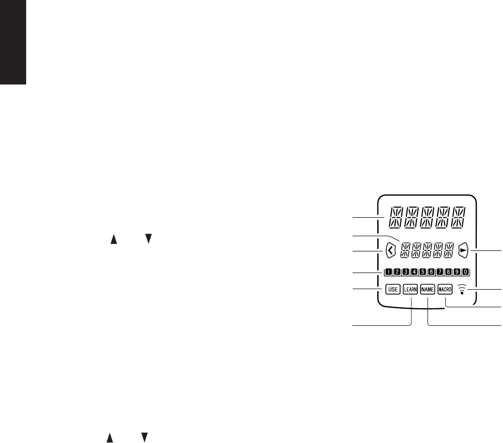
18
ENGLISH
mENT buttons
Used to execute a function selected with the Jog Dial n.
There are 2 ENT buttons, one on each side, so that the remote
controller can be used just as easily with either hand.
The characters on the display can also be programmed.
,Function buttons
Used to switch the remote controller to the command sets for specific
sources (amplifier, receiver, etc.), thereby allowing a single remote
controller to control up to 11 different components. To use these
buttons to switch the amplifier’s source, press the desired button twice
within 2 seconds. The AMP button , is used only to switch command
set of the remote controller itself and therefore does not transmit any
signal. Further, the function buttons may also be programmed to
execute macros. (A macro allows a complex string of operations to be
performed in series simply by pressing a single button.) One button
can be programmed to learn sequences containing up to 10
commands. The following is an example of such a sequence that can
be activated automatically using a macro:
Turn the receiver ON → Switch the function to DVD → Set the
Surround Mode to Dolby Digital → Switch the TV to video input → Set
the DVD player to Play.
.VOLUME up / down button
Used to adjust the volume on receivers and other components
equipped with volume control.
⁄0 CURSOR/TRANSPORT CONTROL buttons
Used to operate on-screen and other displays used by receivers and
other components, as well as to operate the PLAY, STOP, PAUSE,
NEXT, and PREVIOUS functions of each source.
⁄1 < • 3 (CURSOR/ TRANSPORT
CONTROL switching) button
Used to switch the function of the CURSOR/ TRANSPORT
CONTROL buttons ⁄0between the CURSOR and TRANSPORT
CONTROL functions, with the currently selected function displayed on
the LCD when the DVD or VCR functions are selected. When
functions other than DVD or VCR are selected, the < • 3 button
remains inactive.
⁄2 Channel up / down button
Used to controls the up/down function of tuner, or allows one to cycle
through the tuner presets.
⁄3 MUTE button
Used to temporarily mute the sound for amplifiers, receivers, etc.
⁄4 GUIDE button
Used to call up the on-screen menus used to control DVD players,
digital satellite systems (DSS), and other menu-equipped systems.
⁄5 CLEAR button
Used to clear the contents of memory or programmed functions.
⁄6 MEMO button
Used to program your CD player’s track memory, or to enter a VCR
recording program, and can be used to provide the MEMO function
included with other components in your system.
⁄7 Ten-Key pad/Surround Mode buttons
Used to enter numeric digits, useful for finding a specific track on a
CD, or to tune a preset radio station, etc. When the function is set to
AMP, it is possible to choose Surround Mode, etc.
⁄8 Infrared Transmitter/Receiver Window
Used to transmit remote control signals based on beams of infrared
light to system components. To ensure that these signals are properly
received, make sure that this window is pointing in the general
direction of the infrared receiver on the amplifier or other components.
This window should also be pointed toward the source remote
controller when using Programmable Learning function.
Note:
The MODE z, MACRO x, and < • 3 (CURSOR/TRANSPORT
CONTROL switching) ⁄1 cannot be programmed.
LCD (Liquid Crystal Display)
Information about currently selected functions and modes is displayed
on the LCD. Pressing any buttons will call up a full display of
information on the status of that function or mode. This display will
disappear after approximately 1 minute, except for the Function
Name indicator a, which is always displayed.
aFunction Name indicator
Displays the name of the currently selected function (DVD, TV, etc.)
using up to 5 characters.
bCommand Name indicator
Displays up to 10 types of commands for each function using up to 5
characters.
cCommand Page indicator
Allows confirmation of current command page. Also, when setting or
transmitting macros, displays information such as the number of
macro steps and the time intervals between command transmissions.
dTransmission indicator
Indicates when the remote controller is transmitting a signal.
eUSE indicator
For normal operation the USE indicator is displayed.
fLEARN indicator
Indicates when the remote controller is in the LEARN mode.
gNAME indicator
Indicates when the remote controller is in the NAME mode and a
function name is being changed.
hMACRO indicator
Indicates when the remote controller is in the MACRO mode.
iCURSOR indicator
Indicates when the CURSOR/TRANSPORT CONTROL button is in
the cursor mode.
a
b
ij
d
h
g
c
e
f
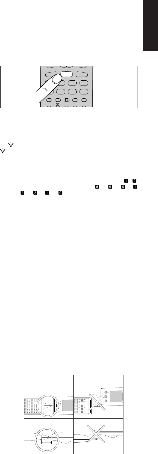
19
ENGLISH
JCONTROL indicator
Indicates when the < • 3 (CURSOR/TRANSPORT CONTROL
switching) ⁄1 is in a transport control mode such as PLAY, STOP, etc.
• If the LCD flickers when a button is pressed in order to transmit a
command or when in the LEARN mode, the transmission or learning
is not possible. In such a case, please replace the batteries.
• This remote controller uses non-volatile memory, so that learned
codes and macros will be preserved even if the batteries are
removed.
BASIC OPERATION
USE MODE
The remote controller will normally be used in the USE mode.
It comes preset with codes commonly used to control 11 types of
components manufactured by Marantz and Philips, including DSS,
DVD, TV, LD, VCR, AUX, TUNER, CD, TAPE, CD-R/MD, and AMP,
as well as many others that utilize the RC-5 remote control language.
1. Press once one of the Function buttons , to change to another
component’s commands, such as DVD button.
2. DVD will be displayed on the LCD and the function codes will be
set to operate the DVD player, and if you double clicked the DVD
function button, the preamplifier or receiver’s input will be
changed as well.
3. Now you can operate the DVD player. When a button is pressed,
the symbol indicates that a remote code is being transmitted.
is not displayed if a button for which no code has been set is
pressed.
4. The Jog Dial n is used to select any one of up to 10 direct
operations that can be performed for each of the 11 functions (DVD,
TV, AMP, etc.). Rotate the Jog Dial n to select one of these
commands. The number of the current page is indicated by - .
Page numbers cycle up or down, for example → → →
→ etc. or → → → → etc. depending on which way the
Jog Dial n is rotated.
The last page position for any given command function is retained
in the memory even if the remote controller is switched to the
command function for another component. (Last Memory)
If it is left for approximately 1 minute without pressing any buttons,
all items on the LCD will go off except the function indicator.
Even if the display goes off, the remote controller will hold the
page position and other data. The display may be activated again
by pressing any button.
LEARN MODE
The remote controller is capable of learning and memorizing the
remote control codes used by almost any other remote controller you
may already own.
• If no commands have been programmed for a particular function
button, the remote controller will transmit whatever codes have
been factory preset.
• The following example shows how to program your remote
controller and how to use the codes for a DVD player.
• The remote controller infrared receiver is located at the top of the
remote controller.
1. Use a ballpoint pen or other sharp point to press the MODE button
z until the LEARN indicator is displayed. Each time you press
this button, the mode will cycle through LEARN → NAME → USE.
Stop when the LEARN indicator starts to blink.
2. Place the DVD’s remote controller so that its infrared signal
transmitter is facing the infrared signal receiver on the Marantz
remote controller at a distance of about 5 centimeters (2 inches).
MEMO
CLEAR
GUIDE MUTE
CD DVD
CD-R/MD
DSS T V VCR
AMP
LD
TUNER
TAPE
AUX
AUTO DTS CS5.1 6.1
LD
DVD
ON OFF
ON /OFF
SOURCE
MACRO MODE
LEARNING REMOTE
CONTROL RC 72
00SR
POWER
ON OFF
ON /OFF
SOURCE
MACRO MODE
LEARNING REMOTE
CONTROL RC 72
00SR
POWER
5 cm
Side View Side View
Top View Top View
DVD remote
control unit
DVD remote
control unit
DVD remote
control unit
DVD remote
control unit
RC7200SR
RC7200SR
RC7200SR
OK NO GOOD
RC7200SR
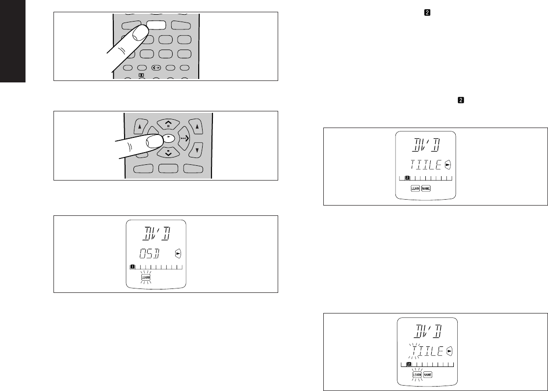
20
ENGLISH
3. Press the DVD Function button ,.
4. Press the PLAY button ⁄0 (3 OK). The LEARN indicator changes
from blinking to continuously lit.
5. Press and hold the PLAY button on the DVD player’s remote
controller. The remote controller has finished learning the
command when OK appears on the LCD a.
•If AGAIN appears on the LCD, some error has prevented the
command from being learned. If this happens, simply repeat
the procedure from step 4.
•In the rare event that NG appears on the LCD, it means that
the remote controller you are attempting to learn from uses
special signals that cannot be learned by the Marantz remote
controller.
6. Follow the same procedure to make the remote controller learn
the ten-key ⁄7 operation used by the DVD player’s remote
controller.
7. Repeat the procedure from step 3 to have the remote controller
learn the signal codes for the other components such as TV, VCR,
etc.
•If no buttons are pressed for approximately 1 minute while in
the LEARN mode, the remote controller automatically returns
to the USE mode.
•When programming the function buttons, first switch to the
desired function, then press the button again.
8. When you have finished programming the remote controller, use a
ballpoint pen or other sharp point to once again press the MODE
button z to return it to the USE mode. The LCD displays the USE
indicator, and the newly programmed codes now can be used.
If FULL is displayed on the LCD
If FULL is displayed on the LCD b when programming in the LEARN
mode, it means that the memory has become too full to hold any
further codes.
If FULL is displayed no matter how many times you attempt to enter
new codes, it means that the remote controller cannot accept any new
codes until some of the previously learned codes are deleted to make
space in the memory. Select unneeded codes for each of the Jog Dial
control n and Function buttons ,, which show FULL and delete
them from the memory.
Note:
The power ON and OFF buttons c can only be programmed to
learn one type of code, regardless of the function button that has
been selected.
PROGRAMMING THE JOG DIAL
Let’s use the example of setting as the TITLE code for the DVD
player.
1. Use a ballpoint pen or other sharp point to press the MODE button
z until the LEARN indicator is displayed and starts to blink.
2. Place the DVD player’s remote controller so that its infrared
transmitter window is facing the infrared signal receiver window
on the Marantz remote controller at a distance of about 5
centimeters (2 inches).
3. Press the DVD Function button ,.
4. Rotate the Jog Dial n left or right until is displayed, then press
the ENT button m.
• The LEARN and NAME indicators will both be displayed.
5. Press the TITLE button on the DVD player’s remote controller
continuously until OK is displayed on the Marantz remote
controller’s LCD, indicating that the programming has been
completed.
•If AGAIN appears on the LCD, some error has prevented the
command from being learned. If this happens, simply repeat
the procedure from step 4.
When the programming has been completed, the remote
controller automatically switches to the NAME mode.
The left hand position on the LCD b blinks, indicating the
character in the name to be rewritten.
•If you do not wish to rewrite the name, simply press the OK
Cursor button ⁄0.
•If you wish to rewrite the name, input the desired characters
using the ten-key pad ⁄7. The part of the display that is being
rewritten may be selected using the < and > Cursor buttons
⁄0. When you are finished rewriting, press the OK Cursor
button ⁄0.
To simply erase already existing characters, press the 0
button to replace them with a blank space.
(Refer to next section on rewriting names)
6. Use the same procedure to program the codes for other 1-6 with
the Jog Dial n.
7. When finished programming the codes for each of the buttons,
use a ballpoint pen or other sharp point to press the MODE button
z to return the remote controller to the USE mode. Once USE is
displayed on the LCD, the newly memorized codes are available
for use.
CH
VOL
OK
CD DVD
CD-R/MD
OK
MEMO
CLEAR
GUIDE MUTE
CD DVD
CD-R/MD
DSS T V VCR
AMP
LD
TUNER
TAPE
AUX
AUTO DTS CS5.1 6.1
LD
DVD
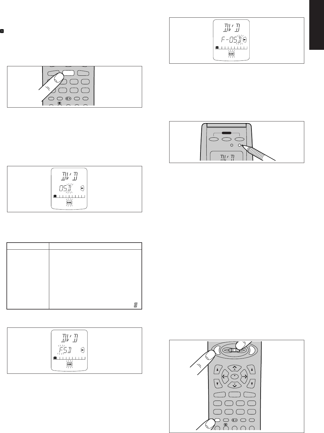
21
ENGLISH
REWRITING NAMES
This remote controller allows the names accessible by Jog Dial
control n to be rewritten with new ones of your choosing.
•Rewriting of names is performed for each individual function.
•Let’s use a DVD player as an example to show how to change the
’s “OSD” to “F-OSD”.
1. Use a ballpoint pen or other sharp point to press the MODE button
z to switch the remote controller to the NAME mode. The NAME
indicator blinks.
2. Press the DVD Function button ,.
3. Use the Jog Dial n to select the page for which you wish to enter
a new name.
4. The character on the left-hand side of the Command Name
indicator on LCD b will flash, indicating that it is the character
ready to be rewritten. New characters entered will be written over
the top of the current character so that the current character is
erased.
Use the < and > Cursor buttons ⁄0 to select the characters to be
rewritten.
5. Use the ten-key pad ⁄7to select the desired alphanumeric
characters.
Pressing the number buttons on the ten-key pad will cycle through
the alphanumeric characters as follows:
Ten keypad Press, press again, press again, etc.
1A → B → C → 1 → A
2D → E → F → 2 → D
3G → H → I → 3 → G
4J → K → L → 4 → J
5M → N → O → 5 → M
6P → Q → R → 6 → P
7S → T → U → 7 → S
8V → W → X → 8 → V
9Y → Z → / → 9 → Y
0
SPACE
→ + → — → , → ’ → 0 →
SPACE
( )
6. For example, to enter the letter “F”, press the 2-key on the ten-key
pad ⁄7 3 times in a row to cycle from D to E to F.
Once the desired character “F” appears, press either of the < and
> Cursor buttons ⁄0 and the “F” will be permanently written over
the former character. Press the 0-key in order to replace
unneeded extra characters with spaces.
7. Follow the same procedure to enter “-OSD”. When finished, press
the OK Cursor button ⁄0. Pressing OK permanently fixes the
newly written characters.
•Up to 5 alphanumeric characters may be entered in the
Command Name indicator of the LCD.
•To rewrite the names of the other items in the Command
Name indicator, use the Jog Dial n to select the desired
command and repeat from step 5.
8. When you are finished rewriting, use a ballpoint pen or other sharp
point to press the MODE button z to return the remote controller
to the USE mode. The USE indicator is displayed on the LCD,
and the newly programmed codes now can be used.
ERASING PROGRAMMED CODES
(Returning to Factory Presets)
Codes that have been programmed into the memory can be erased in
4 ways: by button(s), by function(s), by Jog Dial command, and by
erasing all memory contents.
1. Use a ballpoint pen or other sharp point to press the MODE button
z to switch the remote controller to the LEARN mode, so that the
LEARN indicator is blinking on the LCD.
Note:
Erasing of programmed codes is only possible in the LEARN
mode.
2. Erasing by Button(s)
To erase the codes and names programmed for any button, press
and hold the CLEAR button ⁄5, then press the button to be erased
twice. This will return the button to its factory presets or leave it
empty if no factory presets are available.
Jog Dial codes may be erased in the same way, by pressing and
holding the CLEAR button ⁄5 while using the Jog Dial n to call
up the command to be erased, then pressing one of the ENT
buttons m on either side of the Jog Dial n twice. This will return
the button to its factory presets or leave it empty if no factory
presets are available.
To erase codes programmed for the CLEAR button ⁄5, simply
press the CLEAR button ⁄5 continuously for 3 seconds.
As an example, let’s clear the PLAY command from the DVD
player command set.
ON OFF
ON / OFF
SOURCE
MACRO MODE
POWER
LEARNING REMOTE
CONTROL RC 7200SR
MEMO
CLEAR
GUIDE MUTE
ENT
ENT
CH
VOL
OK
1 23 4 5
CD DVD
CD-R/MD
DSS T V VCR
AMP
LD
TUNER
TAPE
AUX
AUTO DTS CS5.1 6.1
CLEAR
ENT
ENT
MEMO
CLEAR
GUIDE MUTE
CD DVD
CD-R/MD
DSS T V VCR
AMP
LD
TUNER
TAPE
AUX
AUTO DTS CS5.1 6.1
LD
DVD
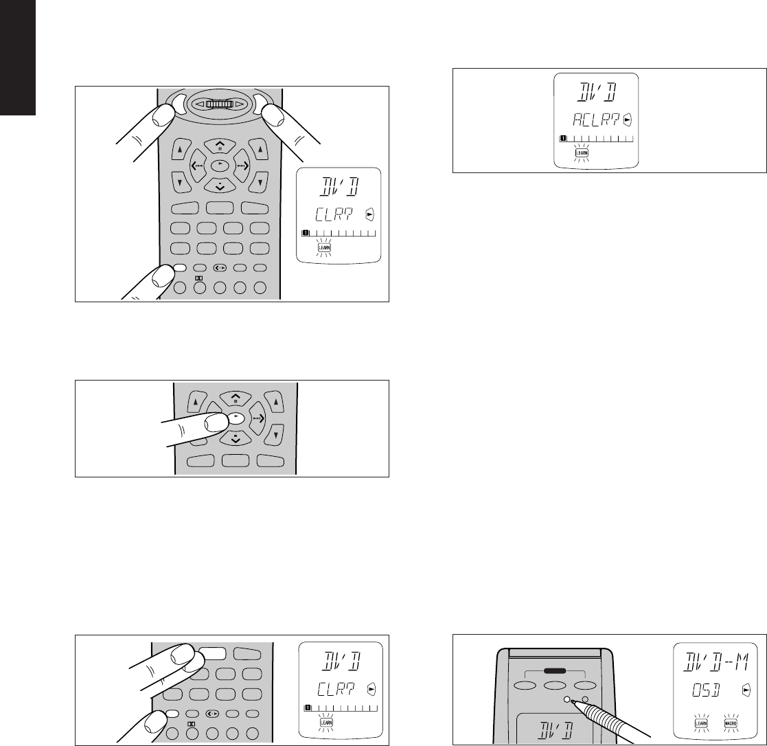
22
ENGLISH
3. Erasing Jog Dial Codes
To clear all codes and names previously set for each of the
functions (DVD, TV, etc.).
1) Press the function you want to erase.
2) Hold down the CLEAR button ⁄5 and press both ENT buttons
m at the same time. LCD b will display CLR?.
3) If you wish to continue the clearing operation, press the OK
Cursor button ⁄0. This will return all 10 commands in the Jog
Dial to their factory presets, or leave them empty if no factory-
presets are available. Accordingly, the LCD b will return to
the factory preset displays, or will simply be empty.
•Use a similar operation to erase the Jog Dial codes for each
function.
•To cancel the memory clearing operation, do not press OK
Cursor button ⁄0 and simply touch any other button.
4. Erasing Code s by Function
To clear all codes and names previously set for each of the
functions (DVD, TV, etc.), press and hold the CLEAR button ⁄5,
then press the button for the function to be cleared twice. CLR?
will appear on LCD b. If you wish to continue the clearing
operation, press the OK Cursor button ⁄0.
This will return the button to its factory-presets or leave it empty if
no factory presets are available. Accordingly, the LCD b will
return to the factory preset displays, or will simply be empty.
•To cancel the memory clearing operation, do not press the OK
Cursor button ⁄0 and simply touch any other button.
•The codes for the < • 3 button ⁄1 cannot be cleared.
5. Erasing All Memory Contents
To clear all the memory contents and reset all codes and names to
their factory presets, press and hold the CLEAR button ⁄5, and
press both the power ON and OFF buttons c simultaneously.
ACLR? will appear on LCD a.
If you wish to continue the clearing operation, press the OK
Cursor button ⁄0.
This will return the entire memory to its factory-presets, or leave it
empty for items for which no factory presets are available.
Accordingly, the LCD will return to the factory-preset display or will
simply be empty.
•To cancel the memory clearing operation, do not press the OK
Cursor button ⁄0 and simply touch any other button.
After the OK Cursor button ⁄0 is pressed, clearing the entire
memory will take approximately 5 seconds.
PROGRAMMING MACROS
Macros make it possible to use a single function button to perform
more complex series of operations that would normally require
pressing several buttons. A single button can be programmed to
perform up to 10 steps in sequence. A typical example of such a series
might be as follows:
•Turn the main amplifier power ON → Switch the function to DVD →
Set the Surround Mode to Pro Logic → Switch the TV to video input
→ Set the DVD player to PLAY.
•No signals may be transmitted during macro programming.
•The various steps that make up a macro are set initially to be sent
one after another in 1 second intervals, however these intervals
may be shortened to as little as 0.5 seconds or lengthened to as
much as 5 seconds using the Setup mode.
•In the macro mode, the number of steps the macro contains is
displayed on LCD c. Macros may be programmed for each of the
11 function buttons, from DVD to AMP.
1. Use a ballpoint pen or other sharp point to press the MACRO
button x until the MACRO and LEARN indicators are displayed
blinking on the LCD.
2. Press the Function button , for which you wish to program a
series of operations. In this case, let’s use the example of the DVD
player.
Press the DVD Function button ,. The LCD a will display DVD-
M.
Characters displayed on LCD a include the following, depending
on the function button for which the macro is being programmed:
LD-M, DVD-M, TV-M, DSS-M, VCR-M, AUX-M, TUN-M, CD-M,
TP-M, AMP-M, CDR-M (or MD-M for remote controller set for
MD).
• If a macro has already been set for the selected function button,
the LCD a will blink. Also, the number of steps in the macro is
displayed on LCD c.
MEMO
CLEAR
GUIDE MUTE
ENT
ENT
CH
VOL
OK
1 23 4 5
CD DVD
CD-R/MD
DSS T V VCR
AMP
LD
TUNER
TAPE
AUX
2CH OSD SLEEP2CH
AUTO DTS CS5.1 6.1
DSP 6
-
STEREO
CLEAR
ENT
ENT
CH
VOL
OK
CD DVD
CD-R/MD
OK
MEMO
CLEAR
GUIDE MUTE
1 23 4 5
CD DVD
CD-R/MD
DSS T V VCR
AMP
LD
TUNER
TAPE
AUX
AUTO DTS CS5.1 6.1
CLEAR
DVD
ON OFF
ON / OFF
SOURCE
MACRO MODE
POWER
LEARNING REMOTE
CONTROL RC
7200SR
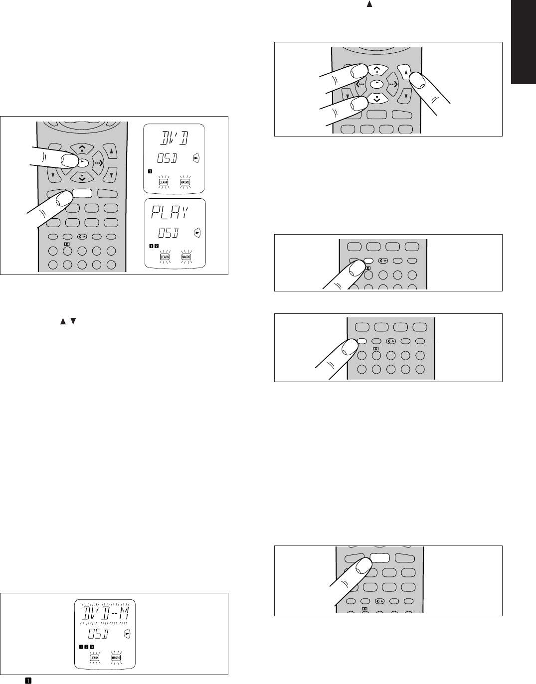
23
ENGLISH
3. Press the buttons for the operations you wish to program as a
macro in the sequence you want the macro to program them. The
name of the button pressed appears on LCD a. The number of
steps in the macro is displayed on LCD c and this number
increases by 1 with each button pressed.
For example, press DVD, PLAY.
Each function button can be programmed to perform up to 10
steps in sequence.
• If, while programming, no buttons are pressed for
approximately 1 minute, the remote controller will
automatically return to normal mode, and no macro will be
programmed in the memory.
4. When you are finished programming macros, use a ballpoint pen
or other sharp point to press the MACRO button x. LCD a will
display END, and the display will return to normal.
•Macros cannot be programmed for the MODE z, MACRO x,
< • 3 ⁄1, VOL / ., MEMO ⁄6 or CLEAR ⁄5 buttons.
In the macro mode it is possible to program the memory to
perform macros containing up to 10 steps.
Each of the function operations (11 including CD, CD-R, etc.)
can be used in a macro more than once, however for all
except AMP, only the first function operation will be
transmitted as a signal from the remote controller.
Accordingly, within a single macro, it is not possible to switch
between multiple function operations. (This is to prevent the
switching of the receiver function operation.) Within a macro,
the second time a function operation is used, it will only be
used on the remote controller itself and no signal will be
transmitted to the component.
EDITING MACROS
Macros may be edited using following procedure.
1. Use a ballpoint pen or other sharp point to press the MACRO
button x until the MACRO and LEARN indicators are displayed
blinking on the LCD.
2. Press the Function button , to be changed. Let’s use the
example of the DVD player, by pressing the DVD Function button
,.
•DVD-M is displayed blinking on LCD a.
•The number of steps in the completed macro is highlighted on
LCD c. In this example there are 3 macro programs in
memory.
The is highlighted if no macros have been programmed,
and the remote controller is ready for macro programming.
3. While pressing the VOL button ., use the ^ and v Cursor
buttons ⁄0 to call up the portion of the macro to be changed.
Pressing the ^ button advances through the macro steps and
pressing the v button regresses through the macro steps.
•To rewrite an existing macro step, simply press the button for
the new step. The old step will be erased and rewritten with
the new step.
•To insert a new step in between existing steps in a macro,
after step 3 press the MEMO button ⁄6 , then press the button
for the new step. The numbers of the other steps will be
adjusted accordingly to accommodate the new step. Since
only 10 steps may be stored in any macro, the tenth step will
be erased if an step is inserted when the total number of steps
is already 10.
• To erase a step in a macro, after step 3 call up the number of
the step to be erased and press the CLEAR button ⁄5.
• If while editing macros no buttons are pressed for
approximately 1 minute, the remote controller will
automatically return to normal mode, and no macro changes
will be programmed in the memory.
4. When you are finished editing macros, use a ballpoint pen or other
sharp point to press the MACRO button x. END will be displayed
on LCD a and the display will return to normal.
USING MACROS
The following procedure will show how to use the function buttons for
which you have programmed macros.
1. Press the Function button , for the desired macro for 3 seconds.
MACRO is displayed on LCD a for approximately 1 second, after
which the number of steps in the macro is displayed on LCD c.
•The remote controller will do nothing if no macros are
programmed. The macro steps are executed in order and the
names of their buttons are displayed on the LCD. Also, the
step numbers displayed on LCD c disappear as each step is
executed.
2. After all macro commands have been transmitted, the remote
controller returns to normal mode.
•To cancel the transmission of a programmed macro, use the
Cursor buttons ⁄0 to press 7.
MEMO
CLEAR
GUIDE MUTE
CH
VOL
OK
1 23 4 5
6 7 8 0
9
CD DVD
CD-R/MD
DSS T V VCR
AMP
LD
TUNER
TAPE
AUX
2CH OSD SLEEP
AUTO DTS CS5.1 6.1
DSP 6-STEREO
OK
DVD
CH
VOL
OK
CD DVD
CD-R/MD
DSS T V VCR AUX
OK
MEMO
CLEAR
GUIDE MUTE
1 23 4 5
6780
9
AMP
LD
TUNER
TAPE
2CH OSD SLEEP
AUTO DTS CS5.1 6.1
DSP 6-STEREO
MEMO
MEMO
CLEAR
GUIDE MUTE
1 23 4 5
6 7 8 0
9
AMP
LD
TUNER
TAPE
2CH OSD SLEEP
AUTO DTS CS5.1 6.1
DSP 6-STEREO
CLEAR
MEMO
CLEAR
GUIDE MUTE
CD DVD
CD-R/MD
DSS T V VCR
AMP
LD
TUNER
TAPE
AUX
AUTO DTS CS5.1 6.1
LD
DVD
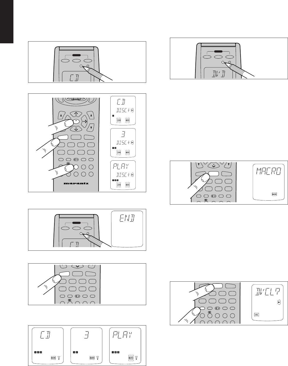
24
ENGLISH
EXAMPLES OF MACRO PROGRAMS
Example 1
Change the input source for the amplifier to CD and play the 3rd track
on a CD in the CD player.
1. Use a ballpoint pen or other sharp point to press the MACRO
button x, then press the CD Function button ,. CD-M is
displayed on the LCD.
2. Press CD ,, 3 ⁄7, and 3 ⁄0 buttons.
When you are finished programming the macro, use a ballpoint
pen or other sharp point to press the MACRO button x.
Now, execute the macro you just programmed.
1. Press the CD Function button , for 3 seconds.
2. The macro commands are transmitted to the components in
order, and the names of the operations being performed are
displayed on the LCD in order.
Example 2
Turn the main amplifier ON → Change the amplifier’s input source to
DVD → Set the Surround mode to DOLBY → Switch the TV to video
input → Set the DVD player to PLAY
1. Use a ballpoint pen or other sharp point to press the MACRO
button x.
2. Press the DVD Function button ,.
•Here the DVD Function button , is used as the macro
button, but any function button can in fact be used.
3. To set the various steps of the macro, press the following buttons
in order: POWER ON c, DVD ,, AMP* ,, 2 (DOLBY) ⁄7, TV*
,, VIDEO (use Jog Dial n to select VIDEO and press ENT
button m) , DVD* ,, 3 ⁄0.
4. When you are finished programming the macro, use a ballpoint
pen or other sharp point to press the MACRO button x. The
remote controller returns to normal mode.
Now, execute the macro you just programmed.
1. Press the DVD Function button , for 3 seconds.
The macro commands are transmitted in order, and the names of
the operations being performed are displayed on LCD a in order.
• When executing this macro, function operations AMP*, TV*,
and DVD* only switch the command set of the remote
controller and no signal is transmitted to the component.
• To cancel the transmission of a programmed macro, use the
Cursor buttons ⁄0 to press 7.
CLEARING MACRO PROGRAMS
The following procedure is used to erase macros you have
programmed into the remote controller’s memory.
1. Press and hold the CLEAR button ⁄5, then the button for the
function , to be cleared (in this case DVD) for 3 seconds.
DVCL? will appear on LCD a. If you wish to continue the clearing
operation, press the OK Cursor button ⁄0.
•To cancel the memory clearing operation, do not press OK
Cursor button ⁄0 and simply touch any other button.
ON OFF
ON / OFF
SOURCE
MACRO MODE
POWER
LEARNING REMOTE
CONTROL RC
7200SR
MEMO
CLEAR
GUIDE MUTE
ENT
ENT
CH
VOL
OK
1 23 4 5
6 7 8 0
9
CD DVD
CD-R/MD
DSS T V VCR
AMP
LD
TUNER
TAPE
AUX
2CH OSD SLEEP
AUTO DTS CS5.1 6.1
DSP 6-STEREO
OK
CD
3
ON OFF
ON / OFF
SOURCE
MACRO MODE
POWER
LEARNING REMOTE
CONTROL RC
7200SR
MEMO
CLEAR
GUIDE MUTE
12345
CD DVD
CD-R/MD
DSS T V VCR
AMP
LD
TUNER
TAPE
AUX
AUTO DTS CS5.1 6.1
CD
ON OFF
ON / OFF
SOURCE
MACRO MODE
POWER
LEARNING REMOTE
CONTROL RC
7200SR
MEMO
CLEAR
GUIDE MUTE
1 23 4 5
6780
9
CD DVD
CD-R/MD
DSS T V VCR
AMP
LD
TUNER
TAPE
AUX
2CH OSD SLEEP
AUTO DTS CS5.1 6.1
DSP 6-STEREO
CLEAR
DVD
MEMO
CLEAR
GUIDE MUTE
CD DVD
CD-R/MD
DSS T V VCR
AMP
LD
TUNER
TAPE
AUX
AUTO DTS CS5.1 6.1
LD
DVD
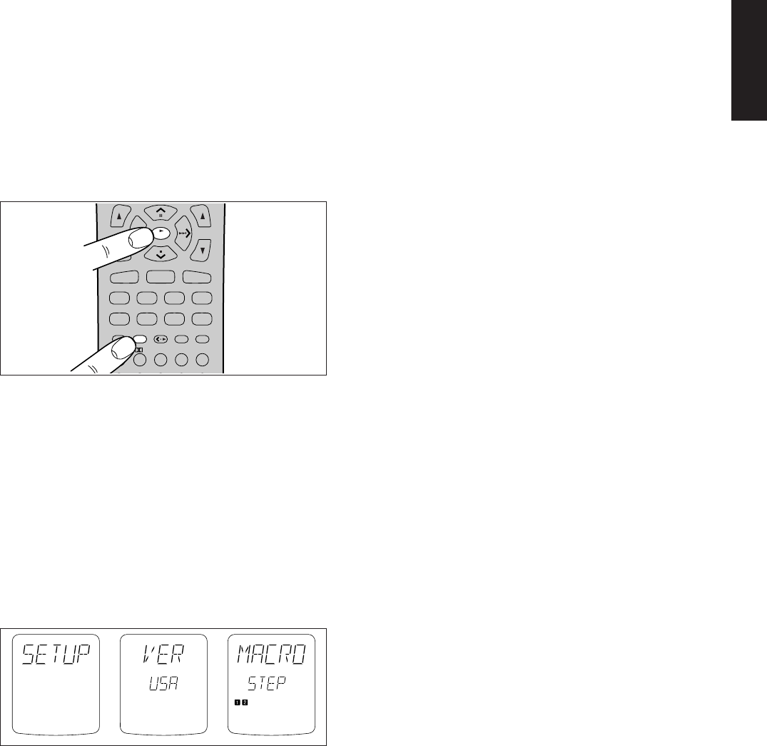
25
ENGLISH
OTHER FUNCTIONS
LUMINOUS BUTTONS
The buttons on this remote controller are designed to remain luminous
in dim lighting conditions. If the buttons are no longer luminous when
the remote controller is used in low light, recharge them by placing it
near a fluorescent or other light source for a sufficient amount of time.
This should return the buttons to their luminous condition.
SETUP
Switch the RC-5 destination or adjust the time interval between
transmissions of macro operations as follows:
1. While pressing the MEMO button ⁄6 , press the OK Cursor button
⁄0. This will switch the remote controller to the Setup mode.
The Setup mode includes the following items, which may be
accessed using the ^ and v Cursor buttons ⁄0.
•Switch destination (version) (VER)
•Adjust time interval between transmissions of macro
operations (MACRO)
VER: Switches the type of preset codes contained in the remote
controller .
LCD a displays VER, while LCD b displays either USA or REST.
USA means that the CD-R/MD Function button , is set to CD-R.
REST means that the CD-R/MD Function button , is set to MD.
Use the < and > Cursor buttons ⁄0 to select the desired version, then
press the OK Cursor button ⁄0. This will finish the operation and return
the LCD to its original state.
•To cancel the setting, press any button other than the Cursor
buttons ⁄0.
•To continue the setting, press the v Cursor button ⁄0.
Note:
Codes that have been programmed will not be erased even if the
VER setting is changed, however the NAME indicator displays
associated with the Jog Dial command will be changed. Also, the
Jog Dial commands for CD-R/MD functions that are contained
within macros will also change.
MACRO: Adjusts the time interval between transmissions of
macro operations
When the v Cursor button ⁄0 is pressed, LCD a displays MACRO,
while LCD b displays STEP.
One square (7) in LCD c is equivalent to an interval of 0.5 seconds,
allowing intervals of up to 5 seconds to be set. The remote controller is
set at the factory with an interval of 1 second, as indicated by
(77&&&&&&&&). Adjust the interval between transmission of
operation codes using the ^ and v Cursor buttons ⁄0, then press the
OK Cursor button ⁄0.
•To cancel the setting, press any button other than the Cursor button
⁄0.
•To continue the setting, press the v Cursor buttons ⁄0.
MEMO
CLEAR
GUIDE MUTE
CH
VOL
OK
1 23 4 5
CD DVD
CD-R/MD
DSS T V VCR
AMP
LD
TUNER
TAPE
AUX
2CH OSD SLEEP
AUTO DTS CS5.1 6.1
DSP 6-STEREO
OK
MEMO
BATTERY LIFE
•New batteries will last about 4 months assuming an average of 30
uses per day.
Note:
The batteries shipped with the remote controller are for the
purpose of checking function and may not last as long as new
batteries.
NUMBER OF LEARNABLE CODES
The remote controller (RC7200SR) uses 128-Kbyte large-capacity
non-volatile memory (EEPROM) and is therefore capable of learning a
maximum of 330 remote control codes. This applies only to Philips
RC-5 remote programming language codes, however, and depending
on the type of other codes that are programmed, the remote controller
can learn less than 330 codes.

26
ENGLISH
JOG DIAL COMMAND FUNCTIONS LISTING
Each of the 10 Jog Dial commands on the LCD has 5 character labels
attached for pre-programmed remote commands. These commands
can be used with various Marantz A/V components, or other
components using the Philips RC-5 remote control language.
You can easily replace the factory-supplied remote command codes
with different codes from other brands of component. Most of the
supplied functions apply to a wide variety of component from many
companies. The following list shows the remote code assignments for
the Jog Dial commands, for each of the 11 Function buttons, as
supplied from the factory. You can add or replace Jog Dial commands,
including re-naming them if you wish, in order to customize the remote
controller for your own particular selection of A/V components.
Function
Jog Dial command
Note
AMP 1 A/D switches analog/digital input
2 ATT switches attenuator for analog input
3 NIGHT selects NIGHT mode for Dolby Digital
4 MR-ON turns multi-room mode on
5 MR-OF turns multi-room mode off
6 7-DIR activates 7-channel input
7 TRB+ increases treble
8 TRB- decreases treble
9 BAS+ increases bass
0 BAS- decreases bass
TUNER 1 FM FM band
2 AM AM band
3 LW Long Wave band
4 T-MOD mono/stereo mode selector
5 SCAN programmed preset channel scan
6 STM selects station mode
7 F-DIR inputs a frequency directly
8 PTY selects PTY function
9 DISP selects display function
0 DWR selects DSR wave range
TV 1 A/CH alternate channel
2 100S 100's
3 VIDEO selects video
4 INFO information
5 S-PIC smart picture
6 S-SND smart sound
7 S-CH smart channel
8 ADV advance
9 OSD activates on-screen display
0 MENU menu
CD 1 DISC+ CD changer next disc
2 DISC- CD changer previous disc
3 TEXT activates text function
4 SHUFL shuffle play function
5 REPT repeat function
6 TRAY tray open/close
7 AMS automatic music scan
8 TIME time display elapsed/remaining/total
9 FF fast forward
0 REW rewind
⊗ LD 1 SID-A side A
2 SID-B side B
3 DISP display on/off
4 AMS automatic music scan
5 AUDIO selects audio mode
6 RPT-A repeat A start point
7 RPT-B repeat B stop point
8 CP/F selects chapter or frame
9 EDIT activates edit function
0 D/CX selects digital audio/analog audio/CX NR
TAPE 1 TP-A selects tape deck A
2 TP-B selects tape deck B
3 DIR auto reverse direction
4 TIME time display
5 TRAY tray open/close
6 AMS automatic music scan
7 REC record
8 PAUSE pause
9
0
Function
Jog Dial command
Note
VCR 1 REC record
2 SLCT selects TV or VCR
3 2XPLY twice normal playback speed
4 SLOW slower than normal playback speed
5 STIL still frame
6 OTR one touch recording
7 AUDIO audio track selector
8 SKIP skip to next program marker
9 VIS+ VHS index search next
0 VIS- VHS index search previous
DSS/V2 1 DISP brings up on-screen channel marker
2 PREV goes to previously selected channel
3 SELCT selects TV or VCR
4 AUDIO audio track selector
5 FAV favorite users and channel lists
6 ALT alternate audio channel, languages
7 FTCH brings up on-screen channel logos
8ANT select broadcast or cable antenna
9 REC record
0 OTR one touch recording
AUX 1 No pre code data
2 No pre code data
3 No pre code data
4 No pre code data
5 No pre code data
6 No pre code data
7 No pre code data
8 No pre code data
9 No pre code data
0 No pre code data
DVD 1 OSD activates on-screen display
2 TITLE selects title menu
3 ZOOM zoom mode on/off
4 MENU selects main menu
5 10+ digit entry +10
6 SETUP selects setup menu
7 ANGLE selects angle
8 SUB-T selects subtitle
9 RESUM resume function
0 AUDIO selects audio
For USA setups
Function
Jog Dial command
Note
CDR 1 INPUT selects input source
2 INCR increments track number
3 SYNC activates SYNCRO. recording
4 REC records pause
5 PROG activates program mode
6 TRAY tray open/close
7 DISP display mode
8 FINAL finalizes (writes TOC)
9 BLANK records blank
0 REPT activates repeat mode
For REST setups
Function
Jog Dial command
Note
MD 1 REC records pause
2 REPT selects repeat mode
3 RANDM random play
4 DISP selects display mode
5 EDIT selects edit mode
6 EJCT eject
7 LP selects SP/LP mode
8 DEL selects delete
9 ENTER selects enter
0 SYNC SYNCRO. recording
The marked “⊗” commands are not used for SR7200.
⊗
⊗
⊗

27
ENGLISH
SURROUND MODES
The SR7200 incorporates digital signal processors (DSP) which can reproduce various surround effects you experience in concert halls and movie
theaters, etc. These Surround Modes, are provided to reproduce a variety of surround sound effects, according to the content of the source to be played.
Surroud mode
1. AUTO
2. STEREO
3. 2
MOVIE
MUSIC
PRO
LOGIC
4. DTS
5. 6.1CH
Surround
6. MOVIE
HALL
STADIUN
MATRIX
7. VIRTUAL
8. CS5.1
9. 6CH
STEREO
Caution for 96kHz PCM-audio signal:
This signal can be played when a DVD-player or DAT-player
connected to the SR7200 is capable of 96 kHz PCM output. For
details, refer to the player’s operation manual.
The signal can be played when STEREO or AUTO has been selected
for the Surround mode.
Some DVD formatted discs featured copy protect. When use such
disc, 96 kHz PCM signal is not output from the DVD player. For
details, refer to the player's operation manual.
Caution for DTS signal:
This signal can be played when the connected DVD-player, laser-
disc player or CD-player is capable of DTS-digital output. For
details, refer to the player's operation manual.
Depending on the player used, DTS play may produce noise. If that
happens, set the Surround mode to DTS.
Playing a DTS-CD or DTS laser disc causes the player’s analog
output terminal to output noise. Before playing DTS sources, be
sure to connect the player’s digital output to the SR7200’s digital
input. Be careful when connecting the output of these players to
analog audio input.
Note that the SR7200 has the following restrictive functions built in
to reduce noise emission as much as possible.
If DTS is selected while in the Surround mode, digital input cannot
be switched to analog input. When the analog input function has
been selected, Surround mode cannot be switched to DTS.
While signals from DTS-laser disc or CD are playing in another
Surround mode, you cannot switch to digital input or from digital
input to analog input.
FEATURES
When this mode is selected, the receiver determines whether the digital input signal is Dolby Digital, PCM-audio or DTS.
Note:
When a Dolby Digital or DTS signal is input, the number of channels for which the corresponding signal is encoded will be
played.
Inputting a Dolby Digital two channel signal with Dolby surround status automatically subjects that signal to Pro-Logic
processing before play.
96 kHz source material can be playback in this mode.
This mode bypasses all surround processing.
Stereo program sources the left and right channels play normaly when PCM-audio or analog stereo is input.
With Dolby Digital and DTS sources, the 5.1 multi-channels are converted to two channel stereo. 96 kHz source material can be
playback in stereo mode.
This mode is used with source materials encoded in Dolby Digital and Dolby Surround.
Dolby Pro Logic II brings the excitement of surround sound to any stereo mix, while making existing Dolby Surround mixes
sound more like discrete 5.1 channels Surround sound.
Dolby Pro Logic II has below 3 modes.
This mode provides 5.1 channel surround sound from Dolby Surround encoded stereo movie sound tracks.
This mode provides 5.1 channel surround sound from conventional stereo sources, analog or digital, such as CD, tape, FM, TV,
stereo VCR, etc.
This mode emulated original Dolby Pro Logic decoding (3/1 surround) suit for Dolby Surround encoded stereo movie
soundtracks.
Note:
PCM-audio signals can be subjected to Pro Logic processing when the sampling frequency is 32 kHz, 44.1 kHz or 48 kHz.
When a signal in another format is input, output will be muted.
This mode is for DTS encoded source materials such as LASER DISC, CD, and DVD.
The DTS mode cannot be used when an Analog input has been selected. When the signal in another digital format is input,
output will be muted.
This mode reproduces 6.1 channel sound field by extracting the surround center information from surround left and surround
right channels.
This mode is suited for 6.1 channel encoded material such as Dolby Digital Surround EX and DTS-ES.
Note:
Dolby Digital 5.1ch and DTS source material can be playback in this mode.
These modes provide surround effect processing from each input source material.
They will produce theater, concert hall and stadium like atmospheres. Select as your taste desires.
Note:
PCM-audio (32 kHz, 44.1 kHz or 48 kHz) and analog source material can playback in this mode.
This mode create the virtual surround sound with the front right and left speakers.
Note:
The 96 kHz sampling frequency and DTS source material mutes output.
This mode is backward compatible, such that surround sound playback is possible from any stereo or passive matrix-encoded
material. Five full-bandwidth, discrete channels of information can be extracted from an enormous library of material not
encoded in Dolby Digital or DTS.
Note:
PCM-audio (32 kHz, 44.1 kHz or 48 kHz) and analog source material can play back in this mode.
This mode is used to create a wider, deeper and more natural soundstage from two channel source material.
This is done by feeding the left channel signal to both left front and left surround speaker and the right channel signal to both
right front and right surround speaker. Additionally, the center channel reproduces a mix of the right and left channel.
Note:
The 96 kHz sampling frequency mutes output.

28
ENGLISH
The relation between the selected surround mode and the input signal
The surround mode is selected with the surround mode selector knob of the SR7200 or the remote control unit. However, the sound from the
speakers depend upon the relationship between the selected surround mode and the input signal. They are as follows;
Note:
•Dolby Digital (2 ch: Lt/Rt): signal with Dolby Surround flag Speakers are full set.
•When DOLBY DIGITAL, DTS, PCM or ANALOG is blinking, the selected surround
mode is unavailable for input signal. Select the other appropriate surround mode to
playback.
•No sound outputs from the surround speaker, center speaker and subwoofer if
the DVD disc has no surround data.
L/R : Front speaker
SL/SR : Surround speaker
C : Center speaker
SC : Surround center speaker
SW : Sub woofer speaker
( ): The indicator blinks
Surround Input Signal Output Fluorescent Indicator
Mode L/R
SL/SR
C SC SW Input Indicator Format Status & Surround Mode Temporary Display Status Ch. Status
Auto Dolby Digital (5.1ch)
OOO
-
O
DIGITAL DOLBY, DIGITAL, AUTO >AUTO> L,C,R,SL,SR,LFE
Dolby Digital (2ch)
O
---
O
DIGITAL DOLBY, DIGITAL, AUTO >AUTO> L,R
Dolby Digital (2ch:Lt/Rt)
OOO
-
O
DIGITAL DOLBY, DIGITAL, PRO LOGIC, AUTO >AUTO> L,R, SC
96kHz PCM
O
- - - - DIGITAL PCM, STEREO, AUTO >AUTO>96kHz> L,R
PCM(Audio)
O
---
O
DIGITAL PCM, STEREO, AUTO >AUTO> L,R
Analog
O
---
O
ANALOG STEREO, AUTO >AUTO> -
DTS (5.1ch)
OOO
-
O
DIGITAL DTS, AUTO >AUTO> L,C,R,SL,SR,LFE
Stereo Dolby Digital (5.1ch)
O
---
O
DIGITAL DOLBY, DIGITAL, STEREO >STEREO> L,C,R,SL,SR,LFE
Dolby Digital (2ch)
O
---
O
DIGITAL DOLBY. DIGITAL, STEREO >STEREO> L,R
Dolby Digital (2ch:Lt/Rt)
O
---
O
DIGITAL DOLBY, DIGITAL, STEREO >STEREO> L,R, SC
96kHz PCM
O
- - - - DIGITAL PCM, STEREO >STEREO>96kHz> L,R
PCM(Audio)
O
---
O
DIGITAL PCM, STEREO >STEREO> L,R
Analog
O
---
O
ANALOG STEREO >STEREO> -
DTS (5.1ch) O - - -
O
DIGITAL DTS, STEREO >STEREO> L,C,R,SL,SR,LFE
2
Dolby Digital (5.1ch)
OOO
-
O
DIGITAL DOLBY, DIGITAL >DOLBY D> L,C,R,SL,SR,LFE
Movie Dolby Digital (2ch)
OOO
-
O
DIGITAL DOLBY, DIGITAL, PRO LOGIC >PLII MOVIE> L,R
Dolby Digital (2ch:Lt/Rt)
OOO
-
O
DIGITAL DOLBY, DIGITAL, PRO LOGIC >PLII MOVIE> L,R,SC
96kHz PCM - - - - - DIGITAL (PCM), DOLBY, PRO LOGIC >PLII MOVIE>96kHz> -
PCM(Audio)
OOO
-
O
DIGITAL PCM, DOLBY, PRO LOGIC >PLII MOVIE> L,R
Analog
OOO
-
O
ANALOG DOLBY, PRO LOGIC >PLII MOVIE> -
DTS (5.1ch) - - - - - DIGITAL (DTS), DOLBY, PRO LOGIC >PLII MOVIE> -
2
Dolby Digital (5.1ch)
OOO
-
O
DIGITAL DOLBY, DIGITAL >DOLBY D> L,C,R,SL,SR,LFE
Music Dolby Digital (2ch)
OOO
-
O
DIGITAL DOLBY, DIGITAL, PRO LOGIC >PLII MUSIC> L,R
Dolby Digital (2ch:Lt/Rt)
OOO
-
O
DIGITAL DOLBY, DIGITAL, PRO LOGIC >PLII MUSIC> L,R,SC
96kHz PCM - - - - - DIGITAL (PCM), DOLBY, PRO LOGIC >PLII MUSIC>96kHz> -
PCM(Audio)
OOO
-
O
DIGITAL PCM, DOLBY, PRO LOGIC >PLII MUSIC> L,R
Analog
OOO
-
O
ANALOG DOLBY, PRO LOGIC >PLII MUSIC> -
DTS (5.1ch) - - - - - DIGITAL (DTS), DOLBY, PRO LOGIC >PLII MUSIC> -
2
Dolby Digital (5.1ch)
OOO
-
O
DIGITAL DOLBY, DIGITAL >DOLBY D> L,C,R,SL,SR,LFE
Pro Logic Dolby Digital (2ch)
OOO
-
O
DIGITAL DOLBY, DIGITAL, PRO LOGIC >PRO LOGIC> L,R
Dolby Digital (2ch:Lt/Rt)
OOO
-
O
DIGITAL DOLBY, DIGITAL, PRO LOGIC >PRO LOGIC> L,R,SC
96kHz PCM - - - - - DIGITAL (PCM), DOLBY, PRO LOGIC >PRO LOGIC>96kHz> -
PCM(Audio)
OOO
-
O
DIGITAL PCM, DOLBY, PRO LOGIC >PRO LOGIC> L,R
Analog
OOO
-
O
ANALOG DOLBY, PRO LOGIC >PRO LOGIC> -
DTS (5.1ch) - - - - - DIGITAL (DTS), DOLBY, PRO LOGIC >PRO LOGIC> -
DTS Dolby Digital (5.1ch) - - - - - DIGITAL (DOLBY, DIGITAL), DTS >DTS> -
Dolby Digital (2ch) - - - - - DIGITAL (DOLBY, DIGITAL), DTS >DTS> -
Dolby Digital (2ch:Lt/Rt) - - - - - DIGITAL (DOLBY, DIGITAL), DTS >DTS> -
96kHz PCM - - - - - DIGITAL (PCM), DTS >DTS>96kHz> -
PCM(Audio) - - - - - DIGITAL (PCM), DTS >DTS> -
Analog - - - - - (ANALOG) DTS >DTS> -
DTS (5.1ch)
OOO
-
O
DIGITAL DTS >DTS> L,C,R,SL,SR,LFE
6.1Ch Dolby Digital (5.1ch)
OOOOO
DIGITAL DOLBY, DIGITAL >6.1 CH SURROUND> L,C,R,SL,SR,LFE
Surround Dolby Digital (2ch) - - - - - DIGITAL (DOLBY, DIGITAL) >6.1 CH SURROUND> -
Dolby Digital (2ch:Lt/Rt) - - - - - DIGITAL (DOLBY, DIGITAL) >6.1 CH SURROUND> -
96kHz PCM - - - - - DIGITAL (PCM) >6.1 CH SURROUND>96kHz> -
PCM(Audio) - - - - - DIGITAL (PCM) >6.1 CH SURROUND> -
Analog - - - - - (ANALOG) >6.1 CH SURROUND> -
DTS (5.1ch)
OOOOO
DIGITAL DTS >6.1 CH SURROUND> L,C,R,SL,SR,LFE
Movie Dolby Digital (5.1ch) - - - - - DIGITAL (DOLBY, DIGITAL), DSP SOUND >
MOVIE/HALL/ STADIUM/MATRIX
>-
Hall Dolby Digital (2ch) - - - - - DIGITAL (DOLBY, DIGITAL), DSP SOUND >
MOVIE/HALL/ STADIUM/MATRIX
>-
Stadium Dolby Digital (2ch:Lt/Rt) - - - - - DIGITAL (DOLBY, DIGITAL), DSP SOUND >
MOVIE/HALL/ STADIUM/MATRIX
>-
Matrix 96kHz PCM - - - - - DIGITAL (PCM), DSP SOUND >
MOVIE/HALL/ STADIUM/MATRIX
>-
PCM(Audio)
OOO
-
O
DIGITAL PCM, DSP SOUND >
MOVIE/HALL/ STADIUM/MATRIX
> L,R
Analog
OOO
-
O
ANALOG DSP SOUND >
MOVIE/HALL/ STADIUM/MATRIX
>-
DTS (5.1ch) - - - - - DIGITAL (DTS), DSP SOUND >
MOVIE/HALL/ STADIUM/MATRIX
>-
Virtual Dolby Digital (5.1ch)
O
- - - - DIGITAL DOLBY, DIGITAL, VIRTUAL >VIRTUAL> L,C,R,SL,SR,LFE
Dolby Digital (2ch)
O
- - - - DIGITAL DOLBY, DIGITAL, PROLOGIC, VIRTUAL >VIRTUAL> L,R
Dolby Digital (2ch:Lt/Rt)
O
- - - - DIGITAL DOLBY, DIGITAL, PROLOGIC, VIRTUAL >VIRTUAL> L,R, SC
96kHz PCM - - - - - DIGITAL (PCM) >VIRTUAL>96kHz> -
PCM(Audio)
O
- - - - DIGITAL PCM, DOLBY, PROLOGIC, VIRTUAL >VIRTUAL> L,R
Analog
O
- - - - ANALOG DOLBY, PROLOGIC, VIRTUAL >VIRTUAL> -
DTS (5.1ch) - - - - - DIGITAL (DTS), DOLBY, VIRTUAL >VIRTUAL> -
CS5.1 Dolby Digital (5.1ch) - - - - - DIGITAL (DOLBY, DIGITAL) >CS5.1> -
Dolby Digital (2ch) - - - - - DIGITAL (DOLBY, DIGITAL) >CS5.1> -
Dolby Digital (2ch:Lt/Rt) - - - - - DIGITAL (DOLBY, DIGITAL) >CS5.1> -
96kHz PCM - - - - - DIGITAL (PCM) >CS5.1>96kHz> -
PCM(Audio)
OOO
-
O
DIGITAL PCM >CS5.1> L,R
Analog
OOO
-
O
ANALOG >CS5.1> -
DTS (5.1ch) - - - - - DIGITAL (DTS) >CS5.1> -
6CH Dolby Digital (5.1ch)
OOO
-
O
DIGITAL DOLBY, DIGITAL >6CH STEREO> L,C,R,SL,SR,LFE
Stereo Dolby Digital (2ch)
OOOOO
DIGITAL DOLBY, DIGITAL >6CH STEREO> L,R
Dolby Digital (2ch:Lt/Rt)
OOOOO
DIGITAL DOLBY, DIGITAL >6CH STEREO> L,R, SC
96kHz PCM - - - - - DIGITAL (PCM) >6CH STEREO>96kHz> -
PCM(Audio)
OOOOO
DIGITAL PCM >6CH STEREO> L,R
Analog
OOOOO
ANALOG >6CH STEREO> -
DTS (5.1ch)
OOO
-
O
DIGITAL DTS >6CH STEREO> L,C,R,SL,SR,LFE
L : Left
R : Right
C : Center
SL : Surround Left
SR : Surround Right
SC : Mono Surround
LFE : Low Frequency Effect

29
ENGLISH
CAUSE
The power plug is not connected.
Mute is on.
The input cable is not connected correctly.
The master volume control is turned all the way down.
The function selector position is wrong.
Input cable connected incorrectly.
Speaker cable connected incorrectly.
The center speaker cable connection is incomplete.
STEREO has been selected for Surround mode.
Center = NONE has been selected in SETUP mode.
The surround speaker cable connection is incomplete.
STEREO has been selected for Surround mode.
Surround = NONE has been selected in SETUP mode.
Sub-woofer = NO has been selected in SETUP mode.
The headphones are connected to the jack.
Analog has been selected for input.
Surround mode is set to DOLBY.
The DVD or LD player is not DTS digital out capable.
Data error occurred during player skip.
The disc player is not 96kHz PCM digital out capable.
Surround mode is set to other than STEREO and AUTO.
Surround mode is set to DTS.
Surround mode is set to DTS
Nothing recorded on source.
Antenna connection is incomplete.
Reception is affected by other electrical fields.
The radio waves from the broadcasting station are weak.
Preset data has been erased.
Batteries are consumed.
Batteries are consumed..
Remote controller's function-key setting is wrong.
The distance between this SR7200 and the remote
commander is too far.
Something is blocking SR7200 and the remote
commander.
SYMPTOM
SR7200 cannot be turned up.
No sound and picture are output
even when power is on.
Sound and pictures from other
than equipment selected with the
function selector.
Sound from the wrong channel is
output from the speaker.
No sound is output from the center
speaker.
No sound is output from the
surround speakers.
No output to Sub Woofer Out.
Surround mode cannot be changed.
Noise is produced during DTS-
encoded CD or laser disc play.
DTS sources cannot be played.
Player skips during play of a DTS
source and produces noise.
A 96kHz PCM signal cannot be
played.
A normal PCM signal (CD or laser
disc) cannot be played.
A Dolby Digital signal cannot be
played.
A specific channel does not
produce output.
FM or AM reception fails.
Noise is heard during AM reception.
Noise is heard during FM reception.
Cannot get programmed station
when the PRESET button is
pressed.
Nothing appears on the remote
commander display.
Control with the remote control unit
fails.
REMEDY
Connect the power plug to the outlet.
Cancel mute using the remote control unit.
See the connection diagram and connect the cables correctly.
Adjust the master volume.
Select correct position.
Connect the cable correctly by referring to the connection diagram.
Connect the cable correctly by referring to the connection diagram.
Connect the cable correctly.
When STEREO is selected for Surround mode, no sound will be
output from the center speaker. Set another Surround mode.
Make the correct setting.
Connect the cable correctly.
When STEREO has been selected for Surround mode, no sound will
be output from the surround speaker. Set another Surround mode.
Make the correct setting.
Select Sub-woofer = YES.
Disconnect the headphones. (When headphones are connected,
Surround mode will be fixed to STEREO.)
Be sure to perform digital connection, select digital input, then play.
Select other mode.
Use a player which responds to DTS-digital out.
Set Surround mode to DTS.
Use a player that responds to 96kHz PCM digital out.
Set Surround mode to STEREO or AUTO.
Select other mode.
Select other mode.
Check the encoded channel on the source side.
Correctly connect the indoor FM and AM antennas to FM and AM
antenna outlets.
Try changing location where the AM indoor antenna is set up.
Install an FM outdoor antenna.
Disconnecting power plug for long periods of time will erase preset
data. If that happens, input the preset data again.
Replace all the batteries with new ones.
Replace all the batteries with new ones..
Select different position from which equipment will be controlled.
Move closer to this SR7200.
Remove offending object.
TROUBLESHOOTING
In case of trouble, check the following before calling for service:
1. Are the connections made properly ?
2. Are you operating the unit properly following user’s guide ?
3. Are the power amplifiers and speaker working properly ?
If the unit does not operate properly, check items shown in the following table.
If your trouble cannot be recovered with the remedy actions listed in
the following table, malfunction of the internal circuitry is suspected;
immediately unplug the power cable and contact your dealer, nearest
Marantz distributor or the Marantz Service Center in your country.

30
ENGLISH
GENERAL MALFUNCTION
If the equipment malfunctions, this may be because an electrostatic
discharge or AC line interference has corrupted the information in
the equipment memory circuits. Therefore:
- disconnect the plug from the AC line supply
- after waiting at least three minutes, reconnect the plug to the AC
line supply
- re-attempt to operate the equipment
Memory backup
•In case a power outage occurs or the power cord is
accidentally unplugged, the SR7200 is equipped with a
backup function to prevent memory data such as the preset
memory from being erased.
The memory functions are backed up for up to about one
week.
NOTE:
First of all keep SR7200 Standby or Powered-on more than 6
hours, to sufficient time for memory back up.
TECHNICAL SPECIFICATIONS
FM TUNER SECTION
Frequency Range ................................................................................................................................................. 87.5 - 108.0 MHz
Usable Sensitivity ............................................................................................................................................. IHF 1.8 µV/16.4 dBf
Signal to Noise Ratio .................................................................................................................................... Mono/Stereo 76/72 dB
Distortion ..................................................................................................................................................... Mono/Stereo 0.2/0.3 %
Stereo Separation ........................................................................................................................................................ 1 kHz 45 dB
Alternate Channel Selectivity ................................................................................................................................ ± 400 kHz 60 dB
Image Rejection ........................................................................................................................................................ 98 MHz 70 dB
Tuner Output Level ............................................................................................................................. 1 kHz, ± 75 kHz Dev 800 mV
AM TUNER SECTION
Frequency Range .............................................................................................................................................. AM: 520 - 1710 kHz
Signal to Noise Ratio .............................................................................................................................................................. 50 dB
Usable Sensitivity .................................................................................................................................................... Loop 400 µV/m
Distortion .................................................................................................................................................. 400 Hz, 30 % Mod. 0.5 %
Selectivity ................................................................................................................................................................ ± 20 kHz 60 dB
AUDIO SECTION
Continuous Power Output (8 ohms / 20 Hz - 20 kHz)
Front ................................................................................................................................................................................. 110 W
Center ............................................................................................................................................................................... 110 W
Surround ........................................................................................................................................................................... 110 W
THD Front (20 Hz - 20 kHz) ..................................................................................................................................... 8 ohms 0.05 %
Input Sensitivity/Impedance
Linear ........................................................................................................................................................... 340 mV/ 47 Kohms
Signal to Noise Ratio
Linear ............................................................................................................................................................................... 105 dB
VIDEO
Television Format ................................................................................................................................................................... NTSC
Input Level/Impedance .......................................................................................................................................... 1 Vp-p/ 75 ohms
Output Level/Impedance ....................................................................................................................................... 1 Vp-p/ 75 ohms
Video Frequency Response ........................................................................................................................ 5 Hz to 8 MHz (– 1 dB)
S/N .......................................................................................................................................................................................... 60 dB
GENERAL
Power Requirement ............................................................................................................................................... AC 120 V 60 Hz
Power Consumption ................................................................................................................................................................ 4.0 A
Dimension (MAX)
Width...................................................................................................................................................... 17-3/8 inches (440 mm)
Height ...................................................................................................................................................... 6-1/2 inches (164 mm)
Depth ..................................................................................................................................................... 15-3/4 inches (400 mm)
Weight............................................................................................................................................................ 32.7 lbs (14.9 Kg)
ACCESSORIES
Remote Control Unit RC7200SR .................................................................................................................................................... 1
AA-size batteries ............................................................................................................................................................................ 2
FM Feader Antenna ....................................................................................................................................................................... 1
FM Antenna Converter ................................................................................................................................................................... 1
AM Loop Antenna........................................................................................................................................................................... 1
Warranty Card (for USA) ................................................................................................................................................................ 1
Warranty Card (for CANADA) ........................................................................................................................................................ 1
User Guide ..................................................................................................................................................................................... 1
Specifications subject to change without prior notice.

Printed in Korea
COUNTRY COMPANY ADDRESS
ALGERIE Azur 2000 8, Lotissement Ben Hatadi, Alger, Algerie
ARMENIA NGYIG Ltd. 47 A/75 St. Lalaiants, 375000 Yerevan, Armenia
AUSTRALIA Jamo Australia Pty. Ltd., 24 Lionel Road, Mt. Waverley, VIC 3149, Australia
AUSTRIA Huber & Prohaska GmbH Taborstraße 95 / Ladestraße 1, Gebäude Hangartner, A-1200 Wien, Austria
BAHREIN Ambassador Stores P.O. Box 237,141, Government Avenue, Manama,Bahrein
BANGLADESH Target 1078, Ramjoy Mohanja Lane Asadgonj, Chittagong 4000, Bangladesh
BELGIUM Van der Heyden Audio N.V. Brusselbaan 278, 9320 Erembodegem, Belgium
BULGARIA Ariescommerce GmbH Makedonia Blvd. 16, 1606 Sofia, Bulgaria
CANADA Lenbrook Industries Limited 633 Granite Court, Pickering, Ontario
CHINA
Guang Chang Audio International Co., Ltd.
No.38 Yushan Road, ShiQiao, Pan Yu, Guang Dong, China
CYPRUS Empire Hifi systems Ltd. P.O. Box 5604, Nicosia, Cyprus
CZECH REPUBLIC Audio International Sokolska 41, 67902 Rajecko, OKR,Blansko, Czech Republic
DENMARK Audio Nord Dali Allé 1, 9610 Noerager, Denmark
DUBAI V.V.& SONS P.O. Box 105, Dubai, U.A.E.
EGYPT Solimco 9, El Attibaa St. Doki, Cairo, Egypt
ESTONIA HiFi Club Estonia Ehte 4, 90503 Haapsalu, Estonia
F.Y.R.O.M. T.P. KODI ul.Cedomir Kantargiev 21a, Skopje, Former Yugoslavian Republic of Macedonija
FINLAND Audio Nord Uudenmaankatu 4-6, Helsinki SF-00120, Finland
FRANCE Marantz France A division of Marantz Europe B.V., P.O. Box 301, 92 156 Suresnes Cedex, France
GERMANY Marantz Deutschland Hakenbusch 3, 49078 Osnabrück, Germany
GREECE Adamco S.A. 188, Hippocratous Street, 11471 Athens, Greece
HEADQUARTERS EUROPE: Marantz Europe B.V. Building SFF-2, P.O. Box 80002, 5600 JB Eindhoven, The Netherlands
HONG KONG Marantz Asia Ltd. Unit 1706, Metroplaza II, 223 Hing Fong Road, Kwai Fong, N.T., Kowloon, Hong Kong
HUNGARY Infovox Ltd. Terez Krt.31, 1067 Budapest, Hungary
ICELAND ID Electronics Ltd. Armula 38, 108 Reykjavik, Iceland
INDIA NOVA Audio Private 8,Punam Co-op.Society 29/30 Road#5, Union Park MUMBAI 400052, India
IRAN Home Co. 5th floor no 878 Philips Building Enghelab ave, P.O. 11365/7844 Tehran, Iran
IRELAND Marantz Ireland Clonskeagh, Dublin 14, Ireland
ISRAEL Elmor Ltd. 52 Heh Beiyar Street, Kikar Hamedina, Tel Aviv, Israel
ITALY Marantz Italy Via Casati 23, 20052 Monza (Milano), Italy, Servizio Consumatori 1678-20026, Numero Verde
IVORY COAST Hifivoir B.P. 2428, Abidjan 01, Ivory Coast
JAPAN Marantz Japan Inc. 35-1 Sagami Ohno 7-Chome, Sagamihara-shi, Kanagawa 228-8505, Japan
KOREA Mk Enterprises Ltd. 121-210, 2F Shinhan Bldg., 247-17 Seokyo-dong, Mapo-ku, Seoul, Korea
KUWAIT alAlamiah Electronics Intl. P.O. Box 8196, Salmiah 22052, Kuwait
LATVIA Ace Ltd. 61, LacPlesa Str., Riga LV 1011, Latvia
LEBANON AZ Electronics S.A., 1, P.O. Box 11 2833, Beirut, Lebanon
LITHUANIA Accapella Ltd. Ausros, Vartu G/5, Pasazo SKG., 2001 Vilnius, Lithuania
MALAYSIA Wo Kee Hong Electronics Sdn. Bhd. Suite 8.1, Level 8, Menara Genesis, No. 33, Jalan Sultan Ismail, 50250 Kuala Lumpur, Malaysia
MALTA Doneo Co Ltd. 78 The Strand, Sliema SLM07, Malta
MAURITIUS SKR Electronics Ltd. P.O. Box 685, Bell Village, Port Louis, Mauritius
MILITARY MARKET EUROPE PASCO GmbH PO BOX 1280, Sandhausen 69200, Germany
NETHERLANDS Marantz Domestic Sales
A division of Marantz Europe B.V., Building SFF2, P.O. Box 80002, 5600 JB Eindhoven, The Netherlands
NEW ZEALAND Wildash Audio Systems 14 Malvern Road, Mt. Albert, Auckland, New Zealand
NORWAY Audio Nord Sandkerveien 64, Oslo 0483, Norway
OMAN Mustafa & Jawad Trading CO. P.O. Box 1918, Ruwi, Oman
POLAND Philips Polska Sp. z.o.o. Al.Jerozolimskie 195b, 02 222 Warszawa, Poland
PORTUGAL Corel2 Comércio de Electrónica Lda., Av. Luís Bívar, No 85 A, 1050 Lisboa, Portugal
PROFESSIONAL EUROPE Marantz Professional Products Kingsbridge House, Padbury Oaks, 575-583 Bath Road, Longford, Middlesex UB7 0EH, U.K.
PROFESSIONAL U.S.A. Marantz Professional Products Distributed by: Superscope Technologies Inc., 1000 Corporate Blvd. Ste.D, Aurora, Illinois
QATAR Almana & Partners W.W.L. P.O. Box 49, Doha, Qatar
REUNION Vision + 180 Rue du Marechal Leclerc, 97400 Saint Denis, Ile de la Reunion
ROMANIA Nova Music Entertainment 5, Zagazului Str. Bl.1G,apt.18, sector 1,Bucharest, Romania
RUSSIA Absolute Audio 7/2, Montazhnaya Street, 107497 Moscow, Russia
SAUDI ARABIA Adawlia Univ. Electr. Apl P.O. Box 2154, Alkhobar 31952, Saudi Arabia
SINGAPORE Wo Kee Hong Distribution PTE Ltd. 130 Joo Seng Road, #03-02 Olivine Building, Singapore 368357
SLOVAKIA Bis Audio s.r.o. Nam. SNP 10, 96001 Zvolem, Slovakia
SLOVENIA Bofex Smartinska 152, HALA V/3, 61000 Ljubljana, Slovenia
SOUTH AFRICA Coherent Imports (PTY) Ltd. P.O. Box 1614, Alberton, 1450, South Africa
SPAIN Marantz Spain Martinez Villergas 2, Apartado 2065, Madrid 28027, Spain
SRI LANKA The listening Room Mezzanine Floor, The Landmark 385, Galle Road, Colombo - 3, Sri Lanka
SWEDEN Audio Nord Almedalsvagen 4, Gotenborg 402-23, Sweden
SWITZERLAND Sound Company AG Postfach, 8010 Zürich, Switzerland
SYRIA Hamzeh & Partners Hafez Ibrahim Str. No 117, Damascus Shalan, Syria
TAHITI Covecolor Av. Prince Hinoi, Cours de l'union sacré, P.O. Box 2334, Papeete, Tahiti
TAIWAN Pai-Yuing Co. Ltd. 6th No 148 Sung Kiang Road, Taipei 10429, Taiwan R.O.C.
THAILAND MRZ Standard Co. Ltd. 746-750 Mahachai Road, Wangburapa, Bangkok 10200, Thailand
TUNESIA Societe EDEVIG 40, Avenue du Golfe Arabe, El Menzah, 1004, Tunesia
TURKEY Türk Philips Ticaret A.S. Yukari Dudullu Organize sanayi Bolgesi, 2.Cadde no.28, 81260 Umraniye-Istanbul, Turkey
U.K. Marantz Hifi UK Ltd. Kingsbridge House, Padbury Oaks, 575-583 Bath Road, Longford, Middlesex UB7 0EH, U.K.
U.S.A. Marantz America Inc. 1100 Maplewood Drive Itasca, IL 60143, U.S.A.
YUGOSLAVIA ITM Company Omladinskih Brigada 86, 11070 Belgrade, Yugoslavia
EXPORT Marantz Domestic Sales
A division of Marantz Europe BV,Building SFF2, P.O. Box 80002, 5600 JB Eindhoven, The Netherlands
www.marantz.com
R is a registered trademark.
01/07 MITi 322W851250
Manufactured under license from Dolby Laboratories. “Dolby”, “Pro Logic”, and the double-D symbol are trademarks of Dolby Laboratories.
“DTS”, “ES” and “DTS Digital Surround” are trademarks of Digital Theater Systems, Inc.
Circle Surround and the symbol are trademarks of SRS Labs, Inc.
Circle Surround technology is incorporated under license from SRS Labs, Inc.
