Marconi Communications 05HAA00105AAT Point to Point Broadband Communication System User Manual ODU 24 GHz
Marconi Communications GmbH Point to Point Broadband Communication System ODU 24 GHz
Users Manual

Access Radio
ODU 24 GHz
User and Installation Manual
Doc number 05PHAxxxxxyyy
Version: DRAFT 08.2005
Marconi Communications GmbH
D-71520 Backnang
Telefon (07191) 13-0 Telefax (07191) 13-3212
http://www.marconi.com
Copyright 2005 by Marconi Communications GmbH
(hierin bezeichnet als Marconi)
Änderungen vorbehalten • Gedruckt in Deutschland
Marconi, Marconi Communications, das Marconi Logo,
MDRS, MDMS und ServiceOn Access sind
eingetragene Markenzeichen von
Marconi Communications GmbH.
Windows ist ein eingetragenes Markenzeichen der
Microsoft Corporation, Redmond.
Marconi Communications GmbH
D-71520 Backnang
Telephone +49 (7191) 13-0 Telefax +49 (7191) 13-3212
http://www.marconi.com
Copyright 2005 by Marconi Communications GmbH
(herein referred to as Marconi)
Specifications subject to change • Printed in Germany
Marconi, Marconi Communications, the Marconi logo,
MDRS, MDMS and ServiceOn Access are trademarks of
Marconi Communications GmbH.
Windows is a trademark of Microsoft Corporation,
Redmond

Doc number 05PHAxxxxxyyy Fehler! Verweisquelle konnte nicht gefunden werden.
Version: DRAFT Contents
Contents
1 General Design of Outdoor Units (ODU) ......................................... 3
1.1 Application .................................................................................................................................3
1.2 Information on intended use ....................................................................................................3
1.3 Safety instructions ....................................................................................................................4
1.3.1 Protective equipment ..........................................................................................................4
1.3.2 Voltage................................................................................................................................4
1.3.3 Grounding ...........................................................................................................................4
1.3.4 Lightning .............................................................................................................................4
1.3.5 Weight.................................................................................................................................5
1.3.6 Sources of Danger Through Microwaves ...........................................................................5
2 Mounting the Outdoor Units............................................................. 8
2.1 General information ..................................................................................................................8
2.2 Outdoor Unit mounting restrictions ........................................................................................9
2.2.1 Access Station ....................................................................................................................9
2.2.2 Load capacity of ODU mounts............................................................................................9
2.3 Mast mounting ........................................................................................................................ 10
2.3.1 Mast mounting on a flat roof ............................................................................................ 11
2.3.2 Mast mounting on a sloping roof...................................................................................... 12
2.4 Fixing the mounts................................................................................................................... 13
2.4.1 Mount (AN00074780) ...................................................................................................... 14
2.4.1.1 Mast mounting (76-114 mm mast diameter)........................................................... 14
2.4.1.2 Mast mounting (115-219 mm mast diameter)......................................................... 15
2.5 Mounting and alignment of Outdoor Units .......................................................................... 16
2.5.1 Mount for ODUs............................................................................................................... 16
2.5.1.1 Azimuth alignment................................................................................................... 16
2.5.1.2 Elevation alignment................................................................................................. 16
2.5.1.3 Adjusting the polarization........................................................................................ 17
2.5.1.4 Tuning the polarization............................................................................................ 17
2.5.1.5 Mounting the ODU .................................................................................................. 17
2.5.2 Installation with remote antenna...................................................................................... 19
2.5.3 Connecting the system cable to the ODU ....................................................................... 21
Labeling Outdoor Units................................................................................................................... 21
2.6 Polarization change with parabolic reflector (0.26 m, 0.3 m, 0.6 m antenna)................... 23
Page 1 Proprietary Information Marconi

Doc number 05PHAxxxxxyyy Fehler! Verweisquelle konnte nicht gefunden werden.
Version: DRAFT List of Figures
List of Figures
Figure 2-1 Obstacle-free azimuth angle .............................................................................................9
Figure 2-2 Obstacle-free elevation angle ...........................................................................................9
Figure 2-3 Mast mounting on a flat roof...........................................................................................11
Figure 2-4 Mast mounting on a sloping roof ...................................................................................12
Figure 2-5 Mast mounting (76 -114 mm) of mount MK3 .................................................................14
Figure 2-6 Mast mounting (115-219 mm) with mounting kit adapter ...........................................15
Figure 2-7 Mounting the parabolic antenna - side view .................................................................18
Figure 2-8 Mounting the parabolic antenna.....................................................................................19
Figure 2-9 Schematic drawing of setup with remote antenna .......................................................20
Figure 2-10 Sealing the plug-connector on the ODU......................................................................21
Figure 2-11 Potential location of Caution Label ..........................................................................22
Figure 2-12 Adjusting the vertical polarization ...............................................................................24
Figure 2-13 Adjusting the horizontal polarization...........................................................................25
List of Tables
Table 2-1 Recommended mast size..................................................................................................10
Table 2-2 IF cable lengths..................................................................................................................13
Page 2 Proprietary Information Marconi

Doc number 05PHAxxxxxyyy Fehler! Verweisquelle konnte nicht gefunden werden.
Version: DRAFT General Design of Outdoor Units (ODU)
1 General Design of Outdoor Units (ODU)
1.1 Application
The present document gives an overview of the technical characteristics of
AXR Outdoor Units (ODU) for the frequency range:
• 24.25 to 24.45 GHz paired with 25.05 to 25.25 GHz
In addition, it describes the installation of the Outdoor Units and the different
mounts and brackets required for this purpose.
1.2 Information on intended use
The radio unit may only be operated for the purposes defined in the operating
manual and within the parameters specified (such as transmit power,
transmission bit rate, frequency band, modulation procedure and safety
clearance from the antenna to avoid any damage to health from electro-
magnetic fields etc.).
Any change in the technical features and location may lead to the operating
permit becoming null and void.
Operation of the radio system is provided in many countries and is subject to
the operating conditions prevailing in each country. Operation is permitted only
with the approval of the authorities responsible for frequency management in
your country, in agreement with the operating regulations prevailing for a fixed
radio service in the frequency band (channel) intended. This permit must be
obtained prior to commissioning the system.
Note Only appropriately trained personnel may carry out installation and
operation work.
Page 3 Proprietary Information Marconi
Doc number 05PHAxxxxxyyy Fehler! Verweisquelle konnte nicht gefunden werden.
Version: DRAFT General Design of Outdoor Units (ODU)
1.3 Safety instructions
Installation and maintenance work may only be carried out by personnel with
the required technical qualification and experience. The installation and
maintenance personnel must be aware of possible sources of danger and take
the necessary measures to reduce possible risks to a minimum.
1.3.1 Protective equipment
Protect yourself and passers-by against dangers!
When installing the Outdoor Units, the service personnel must use
appropriate safety equipment to prevent units or equipment
(particularly the Outdoor Unit, and mounting set) from falling down,
thus preventing damage to units and injury to service personnel and
passers-by.
The recommended protective equipment (helmet, gloves, safety belt
etc.) must be worn during the installation. Observe the national and
regional regulations and requirements.
1.3.2 Voltage
CAUTION! Battery voltage!
The ODU is powered with the 48/60 V DC supply voltage via the inner
conductor of the system cable.
1.3.3 Grounding
Dangerous electrical voltage!
Improper grounding can apply dangerous electrical voltages to
housing parts!
1.3.4 Lightning
Lightning!
You may only install the ODUs if the mast is grounded according to
regulations. Grounding must comply with the relevant regional
regulations.
Mounting work must not be carried out during or directly before
thunderstorms and must be stopped immediately the storm
commences.
Page 4 Proprietary Information Marconi
Doc number 05PHAxxxxxyyy Fehler! Verweisquelle konnte nicht gefunden werden.
Version: DRAFT General Design of Outdoor Units (ODU)
1.3.5 Weight
Danger of injury!
The described units are very heavy. Handle them carefully and wear
suitable protective clothing (shoes).
1.3.6 Sources of Danger Through Microwaves
Danger due to electromagnetic radiation!
In order to avoid any hazards through electromagnetic radiation
caused by microwave radio Tx power, the transmitter must be
switched off before you start working at or near the antenna. If you
have to work for a longer period while transmission is active, please
stay only behind the antenna.
Possible hazards
Potential health hazards can occur due to exposure to electromagnetic fields if
the prescribed safety distances to the antenna are not observed in the main
beam direction and if the waveguide interfaces are opened while the Outdoor
Unit is on.
Protection measures
• If possible, switch the transmitter off before you disassemble the device or
waveguide interfaces.
• Do not look into open waveguide joints. Do not stand directly in front of
transmit antennas.
• Mind the prescribed safety distances in front of the antennas (specified
below).
• If the safety distances cannot be maintained, the power supply to the
antenna must be reduced or the transmitter switched off.
Page 5 Proprietary Information Marconi
Doc number 05PHAxxxxxyyy Fehler! Verweisquelle konnte nicht gefunden werden.
Version: DRAFT General Design of Outdoor Units (ODU)
Main beam direction
of antenna
∼
∼
Safety distance
in front of antenna
∼
∼
D/D'
Warning:
Do not open waveguide joints without switching off the
transmitters. Electormagnetic fields can be harmful to the
body (particulary to the eyes) and can also cause rf-interference.
Warning: Mind the safety distance
Permissible limiting values
In DIN VDE 0848 "Safety in Electromagnetic Fields", a distinction is made
between two exposure areas.
LIMITING VALUES AVERAGE POWER FLOW DENSITY
Exposure Area 1
50 W/m2
See also 47 CFR 1.1310
Table 1.A
Exposure Area 2
10 W/m2
See also 47 CFR 1.1310
Table 1.B
See also Official Gazette of the
European Communities
(1999/519/EC)
Exposure Area 1 includes:
• Controlled areas, e.g. operating areas and areas that can be monitored by
the operator.
• Generally accessible areas where, on account of the method of system
operation or the time spent by persons in these areas, it may be assured
that exposure will occur for short periods of time only (up to 6 hours per
day).
Exposure Area 2 includes:
• Residential districts or areas where sports and recreational facilities are
located;
Page 6 Proprietary Information Marconi

Doc number 05PHAxxxxxyyy Fehler! Verweisquelle konnte nicht gefunden werden.
Version: DRAFT General Design of Outdoor Units (ODU)
• General areas where long-term exposure (more than 6 hours per day) is
expected.
A sign or other safety precautions, at the access to the antenna system (e.g.
skylight), is not required if it can be assured that unauthorized persons cannot
approach within the safety distance in front of the antennas.
If this cannot be assured, a suitable sign (No unauthorized entry!) must be
located at the access to the antennas.
In addition, the safety precautions stipulated by the site proprietor for access
and presence in the area of transmitter systems shall be observed.
Safety distances in the area in front of antennas
The evaluation in accordance with the "OET Bulletin 65" (F.C.C.) and with the
"Safety Code 6" (Industry Canada) is performed in separate documents, which
can be provided on request.
Safety distances are not required according to these evaluations.
Page 7 Proprietary Information Marconi

Doc number 05PHAxxxxxyyy Fehler! Verweisquelle konnte nicht gefunden werden.
Version: DRAFT Mounting the Outdoor Units
2 Mounting the Outdoor Units
2.1 General information
Caution!
For all mounting works, please follow the safety instructions described
in the following chapters.
Note Please note that you should not install the Outdoor Unit and then leave it
for long periods of time without a power supply. This can lead to inner
corrosion and defects. It is therefore recommended to coordinate the
installation and commissioning process so that the unit is not left
without power supply for more than ten days.
The Outdoor Units can be mounted either to a mast or wall. The mounting
type required is defined during the planning stage.
Please note the following instructions:
• The Outdoor Units must be connected to a suitable lighting protection
grounding such as the existing lightning protection system.
• Please note that it is not permitted to ground the Outdoor Units to mains
sockets in the building.
• If you mount the ODU to a mast, it should not be positioned at its top, but
about 50 to 100 cm below the top of the mast (lightning protection).
• Carefully mount the Outdoor Unit in the correct position.
• If you mount several Outdoor Units close to each other, e.g. for adjacent
sectors in the Base Station, a spacing of at least 10 cm must be provided
between the individual units in order to avoid interference.
• Make sure that there are no obstacles, such as cables, walls, masts etc.
blocking the "free zone" in front of the Outdoor Unit. If you fear that this
might be possible, please contact the Marconi Network Planning Group.
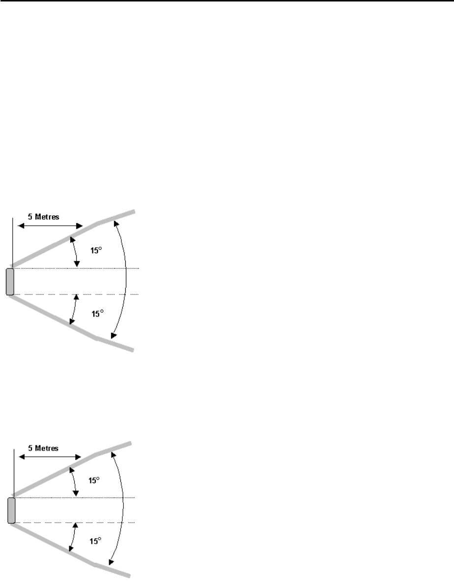
Describe your situation and ask for advice before you continue. Figure 2-1
and Figure 2-2 show the area which must be kept free in the elevation and
azimuth angle.
• Note the maximum load capacity and the operating conditions as indicated
in the technical characteristics.
Page 8 Proprietary Information Marconi
Doc number 05PHAxxxxxyyy Fehler! Verweisquelle konnte nicht gefunden werden.
Version: DRAFT Mounting the Outdoor Units
2.2 Outdoor Unit mounting restrictions
When choosing the mounting site, note the restrictions described in the
following chapters.
2.2.1 Access Station
The areas shown in Figure 2-1 and Figure 2-2 must be kept free from
obstacles such as trees, buildings or cables laid in front of the antenna.
This drawing shows the free zone required in
the azimuth angle for all Terminal ODUs,
measured from the ODU edges.
Figure 2-1 Obstacle-free azimuth angle
This drawing shows the free zone required in
the elevation angle for all Terminal ODUs,
measured from the ODU edges.
Figure 2-2 Obstacle-free elevation angle
2.2.2 Load capacity of ODU mounts
If the Outdoor Unit is installed using the recommended settings, the maximum
wind loads specified in the technical characteristics will be applicable.
Page 9 Proprietary Information Marconi

Doc number 05PHAxxxxxyyy Fehler! Verweisquelle konnte nicht gefunden werden.
Version: DRAFT Mounting the Outdoor Units
2.3 Mast mounting
Mast mounting primarily depends on the specific ODU installation. The
Outdoor Unit can either be mounted to an existing mast or to a mast to be
newly erected.
The procurement of the mast is normally within the responsibility of the
customer. The following instructions must be observed:
• The mast position is usually defined during the site inspection in the
planning process. When selecting the site, note the mounting restrictions
shown in Figure 2-1 and Figure 2-2.
• Make sure that all metallic parts of the mast construction are grounded by
means of a connection to the building lightning protection system.
In each individual case, please observe the national and regional
regulations!
• Fix the Outdoor Unit to the mast so that its top is below the top of the mast.
This considerably reduces the risk that the Outdoor Unit will be struck by
lightning.
• Make the mast as short and stiff as possible to minimize the sway of the
Outdoor Unit in case of strong wind.
Table 2-1 shows the different mast sizes which can be used for
unsupported Outdoor Unit masts under normal operating conditions.
These are only guidelines. Always select the stiffest possible pole.
However, it is recommended to use unsupported masts only up to the
heights indicated in the following table.
FREE MAST HEIGHT DIAMETER OF MAST
POLE
WALL THICKNESS
OF POLE
MAST DISPLACE-
MENT
76.1 mm 3.2 mm 0.06°
2 m 114.3 mm 3.6 mm 0.02°
139.7 mm 6.3 mm 0.08°
4 m 139.7 mm 10.0 mm 0.05°
168.3 mm 10.0 mm 0.11°
6 m 219.1 mm 6.3 mm 0.10°
Table 2-1 Recommended mast size
• Make sure that the mast is installed safely. Bolt through the roof or use a
straddling dowel in concrete or brick surfaces.
• Use a spirit level to verify that the mast is vertical. Use seals at the
mounting points to prevent the ingress of humidity.
Note The customer is responsible for mounting the mast. The following
diagrams only represent a general guideline for mast mounting.
Page 10 Proprietary Information Marconi
Doc number 05PHAxxxxxyyy Fehler! Verweisquelle konnte nicht gefunden werden.
Version: DRAFT Mounting the Outdoor Units
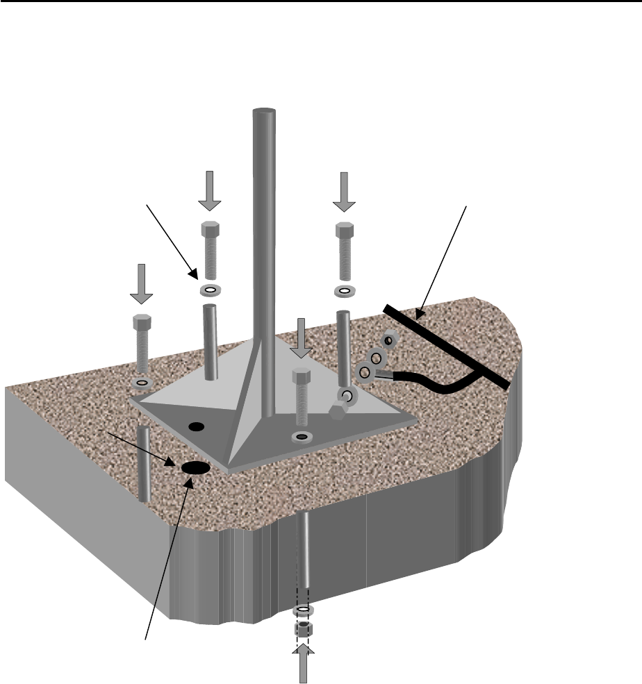
2.3.1 Mast mounting on a flat roof
Connect the mast to the
lightning protection system
(see text).
Fix the mast to the roof using
straddling dowels, or bolt
through the roof.
Seal the bolt openings against the ingress
of water.
Figure 2-3 Mast mounting on a flat roof
Normally, mounting on flat roofs should cause no problems. It is important to
fix the mast structure firmly to the roof, either by bolting through the roof or
using suitable straddling dowels depending on the structure of the roof. Seal
all bolt openings against water ingress.
Connect all metallic parts of the mast to the building lightning protection.
Should such lightning protection not exist in the building, connect the mast
separately to ground using a copper cable. This connection must have a
ground resistance of less than 2 Ohms.
Note When laying the ground connections, observe the local and national
regulations!
Page 11 Proprietary Information Marconi
Doc number 05PHAxxxxxyyy Fehler! Verweisquelle konnte nicht gefunden werden.
Version: DRAFT Mounting the Outdoor Units
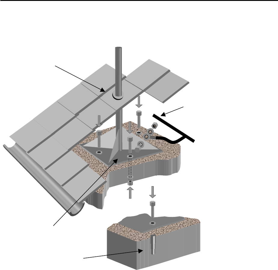
2.3.2 Mast mounting on a sloping roof
Seal the mast where
it passes through the
roof to prevent the
ingress of water.
Connect the mast to the
Lightning protection
system of the building
Bolt the mast to
the internal roof
structure. Make
sure that the
mast is vertical.
A
lternatively, you can use
straddling dowels or rawl
p
lu
g
s to secure the mast.
Figure 2-4 Mast mounting on a sloping roof
Normally, the roof is covered with roof tiles or a similar material which means
that mounting directly on the roof surface would be impossible. You must
therefore install the mast base on a supporting brace or surface beneath the
roof so that the mast protrudes above the roof as shown in the diagram. Then
you must seal the mast at the point it passes through the roof to make it
waterproof.
Connect the metallic parts of the mast to the building lightning protection.
Should such lightning protection not exist, connect the mast separately to
ground using a copper cable. This connection must have a ground resistance
of less than 2 Ohms.
Note When laying the ground connections, observe the local and national
regulations!
Page 12 Proprietary Information Marconi

Doc number 05PHAxxxxxyyy Fehler! Verweisquelle konnte nicht gefunden werden.
Version: DRAFT Mounting the Outdoor Units
2.4 Fixing the mounts
The followings mounts are available for ODU installation:
• Mount (AN00074780)
• Mounting kit adapter (AN00079891)
Mount (AN00074780) is provided for mounting ODUs with a parabolic
antenna. It is approriate only for mast mounting and offers a device required
for antenna fine alignment.
The mounting kit adapter is used together with the above mount for mast
diameters of 115 to 219 mm.
Mounting equipment and tools
We recommend to use the following special tools:
• 13 mm and 17 mm spanner or nut
• Spirit level with digital read-out (e.g. Marconi type DNM 60L)
• Torx screw driver
The installer should also possess the other standard tools for this type of work
(see list of tools).
Before fixing the mount, always ensure that the following conditions are met:
• The line of sight in the direction of the associated Base Station must be
free from obstacles (this should be indicated in the site mounting plans).
• The maximum length of the system cable between the Indoor and Outdoor
Unit must not exceed the lengths specified in the table below. In addition,
the cable route must be free from obstacles.
CABLE TYPE
MARCONI CODE
OUTER DIAMETER MINIMUM BENDING
RADIUS
(MULTIPLE BENDS)
MAX.
LENGTH
O2YS(ST)CH AN00226089 10.2 mm 135 mm 150 m
LCF 14 AN00080254 10.0 mm 120 mm 150 m
LCF 12 AN00087586 15.8 mm 125 mm 300 m
Table 2-2 IF cable lengths
• Make sure that the wall or mast used for attaching the mount must have
the required stability.
Page 13 Proprietary Information Marconi
Doc number 05PHAxxxxxyyy Fehler! Verweisquelle konnte nicht gefunden werden.
Version: DRAFT Mounting the Outdoor Units
2.4.1 Mount (AN00074780)
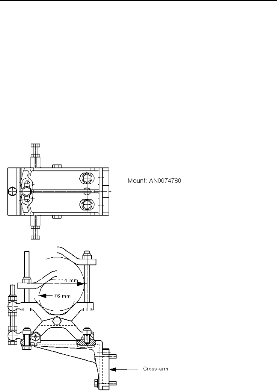
This mount (AN0074780) is provided only for being fixed to masts with
diameters between 76 and 114 mm.
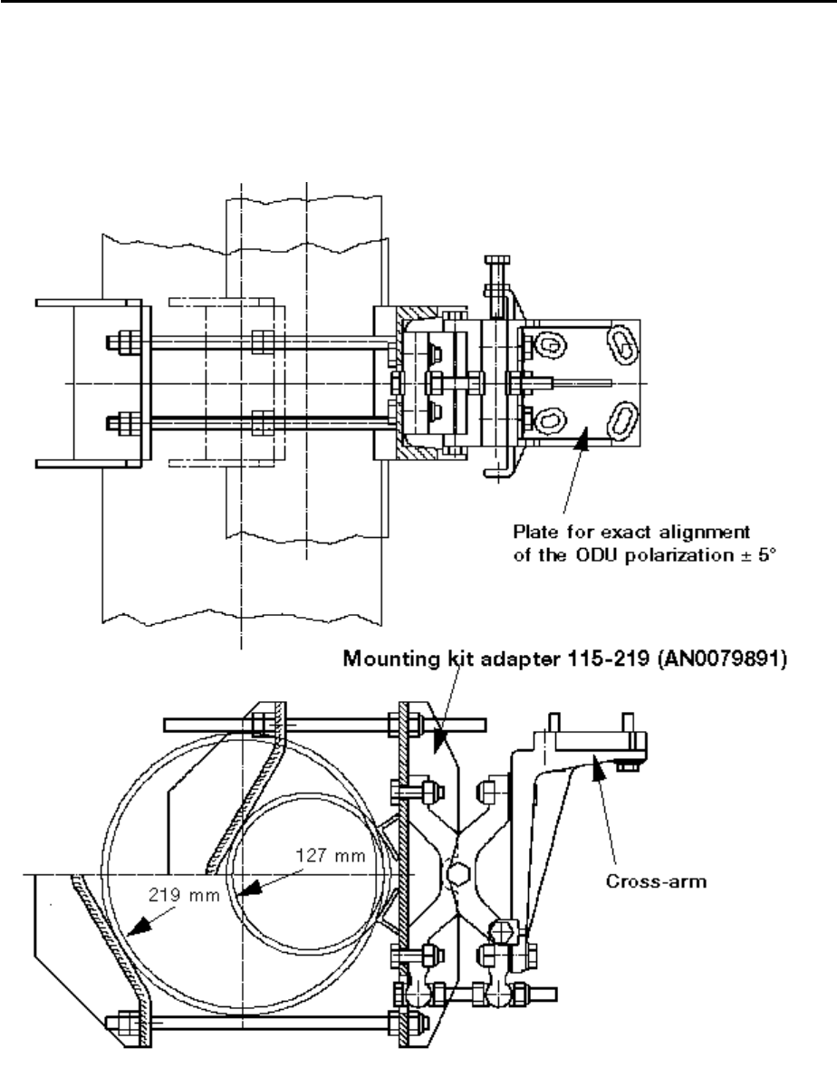
For mast diameters between 115 and 219 mm, an appropriate mounting kit
adapter (AN0079891) is available.
This mount is used to fix ODUs with a parabolic antenna. It offers a special
device required for antenna fine alignment.
2.4.1.1 Mast mounting (76-114 mm mast diameter)
Fix the mounting strap at the required height on the mast and swivel it so that
it is at 90° to the required radiation direction.
Figure 2-5 Mast mounting (76 -114 mm) of mount MK3
Page 14 Proprietary Information Marconi
Doc number 05PHAxxxxxyyy Fehler! Verweisquelle konnte nicht gefunden werden.
Version: DRAFT Mounting the Outdoor Units
2.4.1.2 Mast mounting (115-219 mm mast diameter)
First attach the mounting kit adapter (AN0079891) included in the pole kit
(115-219 mm) to the mast.
Then fix the mount.
Figure 2-6 Mast mounting (115-219 mm) with mounting kit adapter
Page 15 Proprietary Information Marconi
Doc number 05PHAxxxxxyyy Fehler! Verweisquelle konnte nicht gefunden werden.
Version: DRAFT Mounting the Outdoor Units
2.5 Mounting and alignment of Outdoor Units
2.5.1 Mount for ODUs
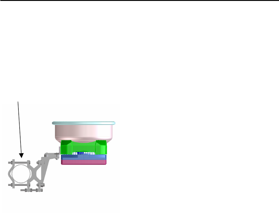
This mount (AN0074780) is used to install ODUs with a separate parabolic
antenna. It is provided for masts with diameters between 76 and 114 mm.
Using the additional mounting kit adapter (AN0079891), mast diameters of up
to 219 mm can be implemented.
Mount
AN0074780
Reflector 0.26m with radome
Antenna 0.3m 05MBH00063AAK
Antenna 0.6m 05MBH00060AAD
Feed
This mount is equipped with setting screws for the antenna fine alignment.
This special device is nessary since a parabolic antenna with its small
aperature angle requires a very high alignment accuracy.
The antenna feed is pre-mounted before the antenna is delivered.
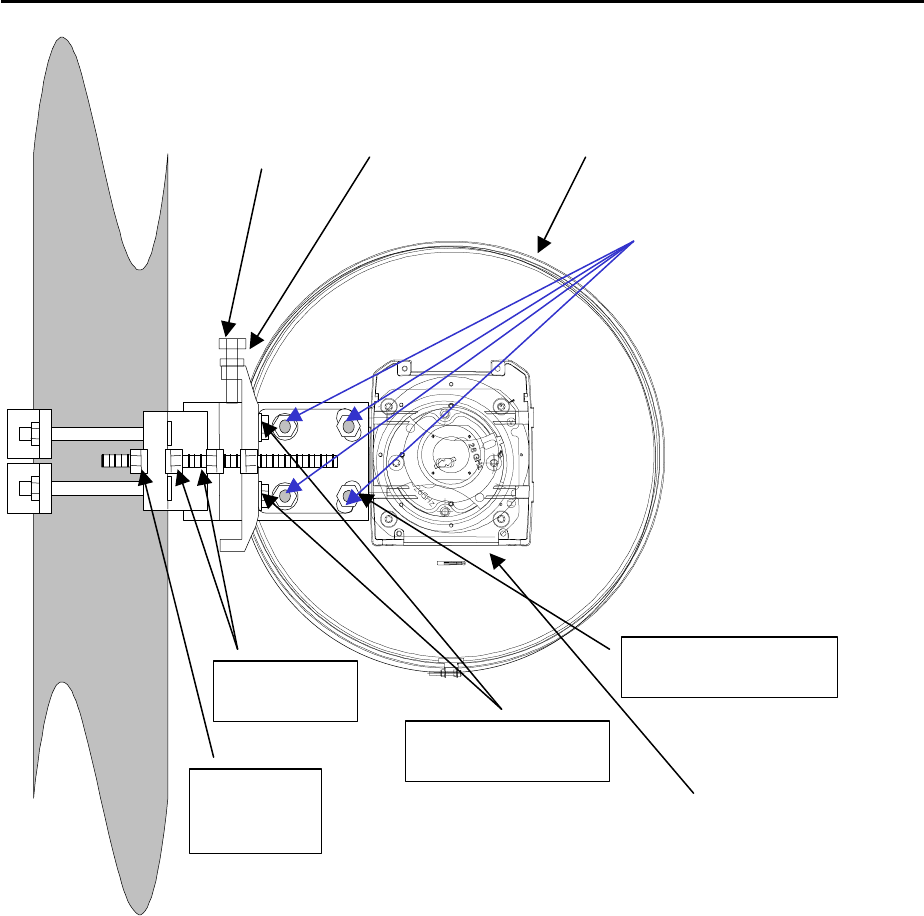
Mount the antenna onto the corresponding bracket by means of three screws
A (see Figure 2-7 and Figure 2-8).
2.5.1.1 Azimuth alignment
Attach a theodolite to the antenna to align the latter to the Base Station. The
Marconi Network Planning Group will specify the exact alignment.
Loosen locking nut B and adjust the position with tuning screw C. Each
rotation of screw C swivels the antenna by 0.9° in the azimuth to up to a
maximum of ± 5°. Tighten nut B when the antenna is correctly aligned.
2.5.1.2 Elevation alignment
Place an electronic spirit level (note length for 60 cm antenna) on the outer
edges of the front of the antenna to set the correct vertical (tilt) angle. The
Marconi Network Planning Group will inform you on the correct tilt angle. An
angle of 0° indicates the horizontal position; a negative angle indicates a
'downwards' tilt of the antenna.
Page 16 Proprietary Information Marconi

Doc number 05PHAxxxxxyyy Fehler! Verweisquelle konnte nicht gefunden werden.
Version: DRAFT Mounting the Outdoor Units
Loosen the three screws A on the antenna mounting bracket and locking nut
D. Then turn setting screw E until the spirit level shows the correct alignment.
One rotation of setting screw E moves the antenna by 0.5° to up to a
maximum of ± 7.5°. Retighten locking nut D and make sure that the angle has
not changed.
2.5.1.3 Adjusting the polarization
See Section Polarization change with parabolic reflector (0.26m, 0.3 m, 0.6 m
antenna).
2.5.1.4 Tuning the polarization
Loosen screws F. Place the spirit level on the lower edge of the rear side of
the antenna (see Figure 2-7). Turn the antenna until it is in the exact horizontal
position, a rotation angle of ± 5° being possible. Then retighen screws F.
Verify that the antenna has not been displaced.
2.5.1.5 Mounting the ODU
Now screw the ODU to the antenna by means of four fixing screws (allen
screw M6).
Page 17 Proprietary Information Marconi
Doc number 05PHAxxxxxyyy Fehler! Verweisquelle konnte nicht gefunden werden.
Version: DRAFT Mounting the Outdoor Units
Mast
Rear of parabolic antenna
Elevation angle adjustment
Screw E and locking nut D
Azimuth locking
nut B
Fix the ground cable
to one of these bolts G
Antenna mounting
screws A (3 pieces)
Azimuth
adjustment
screw C
Apply spirit level
Screws F
Figure 2-7 Mounting the parabolic antenna - side view
Page 18 Proprietary Information Marconi
Doc number 05PHAxxxxxyyy Fehler! Verweisquelle konnte nicht gefunden werden.
Version: DRAFT Mounting the Outdoor Units
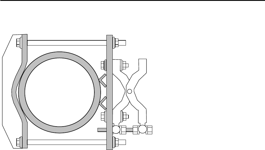
Alternative 115-219 mm mast mounting device with mounting kit adapter.
Mounting bracket and
azimuth setting as
described above
115 -219 mm ∅
Figure 2-8 Mounting the parabolic antenna
2.5.2 Installation with remote antenna
In certain cases of application (e.g. hardly accessible antenna installation
sites), it may be reasonable to install the antenna and transceiver in different
places.
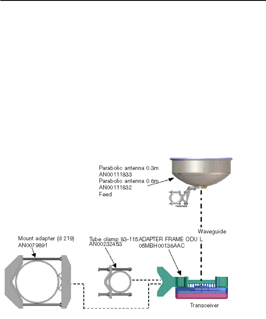
Recommended configuration:
• ODU for mounting with separate antenna
• ODU mount - Adapter frame ODU L (05MBH00136AAC)
• ALFORM 290 waveguides
• transition kits
• Parabolic antenna (including mount)
Optionally, you can use waveguide bends (R220 interface, 1 x H-bend, 1 x E
bend) to permit smaller bending radii for waveguides.
In addition, you require the standard mounting material for waveguides
(sealing rings, pressure window, mounting clamps) as well as the tools
necessary for laying ALFORM waveguides.
Mounting steps:
1. Install the ODU using mount AN00074780. It permits the ODU to be
mounted inside or outside the building.
2. Mount the ODU L adapter frame.
3. Mount the transition kits (note pressure window and seals).
Page 19 Proprietary Information Marconi
Doc number 05PHAxxxxxyyy Fehler! Verweisquelle konnte nicht gefunden werden.
Version: DRAFT Mounting the Outdoor Units
4. Mount the parabolic antenna (see section 2.5.1) and align it as precisely as
possible.
5. Attach the waveguide (normally ALFORM 290) to the transition kits and lay
it according to the standard guidelines.
6. Take the terminal into operation according to instructions. If required, the
fine alignment of the parabolic antenna can be facilitated by temporarily
inserting a short flexible waveguide between the ALFORM waveguide and
parabolic antenna.
Note The insertion loss of the waveguide is compensated by the higher gain
of the parabolic antenna (compared to standard planar antennas). Thus,
there are no restrictions regarding the link range, i.e. the alignment
procedure is still applicable without any modification.
The maximum insertion loss is therefore 5.5 dB.
When using ALFORM 290 waveguides, this corresponds to a maximum
waveguide length of 10 m.
Figure 2-9 Schematic drawing of setup with remote antenna
Page 20 Proprietary Information Marconi
Doc number 05PHAxxxxxyyy Fehler! Verweisquelle konnte nicht gefunden werden.
Version: DRAFT Mounting the Outdoor Units
2.5.3 Connecting the system cable to the ODU
CAUTION! Battery voltage!
The ODU is powered with the 48/60 V DC supply voltage via the
inner conductor of the system cable.
1. Make sure that the mast and ODU are correctly grounded.
Note The system cable may be connected only after the ODU has been
appropriately grounded.
Always connect the system cable to the ODU first and then to the IDU.
2. Connect the IF cable and overvoltage protection - if used - to the rear of the
ODU.
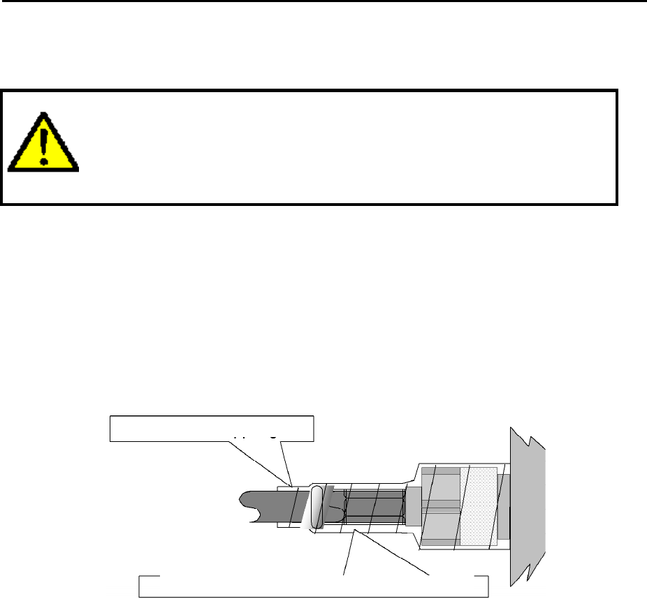
3. Seal the plug connector with self-vulcanizing tape as shown below.
1 cm overlappi ng
Self-vulcanizing Scotch ribbon
Figure 2-10 Sealing the plug-connector on the ODU
Note Please note that the unit should not be left longer than 10 days without
power supply, as this could lead to internal corrosion damage through
condensation.
If the ODU must be left without power for more than 10 days, remove it
from the antenna and store it in a closed room up to its final
commissioning.
2.5.4 Labeling Outdoor Units
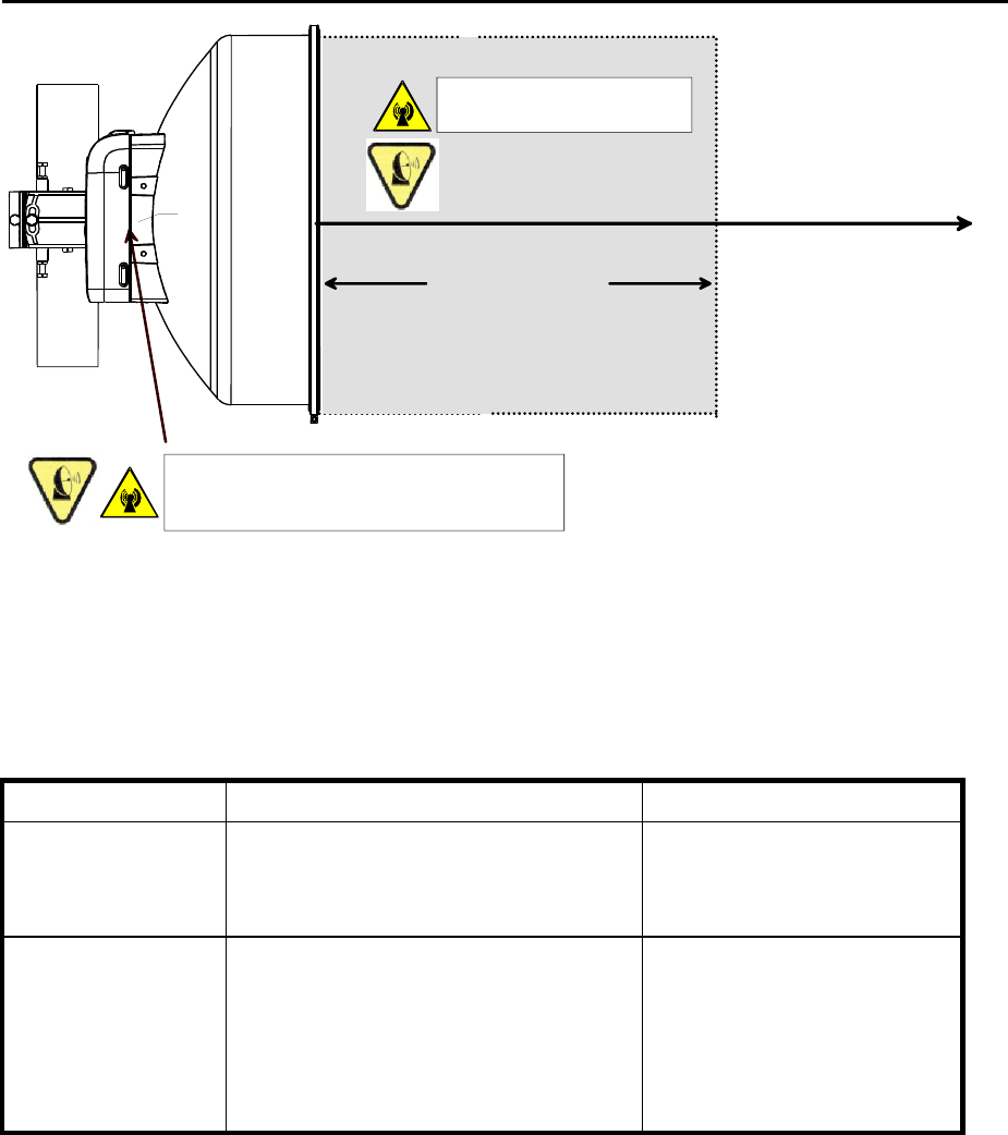
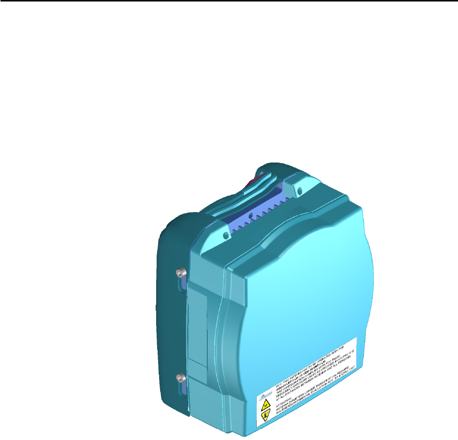
Caution Label for RF-Exposure
For all antennas having diameters larger then 1/2 ft (>15 cm), the maximum
power flux density in front of the antenna is less than 10 W/m² at all distances
(please refer to chapter 1.3.6).
Nevertheless, a Caution Label concerning rf-exposure has to be attached to
the antenna in good visibility.
Page 21 Proprietary Information Marconi
Doc number 05PHAxxxxxyyy Fehler! Verweisquelle konnte nicht gefunden werden.
Version: DRAFT Mounting the Outdoor Units
This Caution Label is delivered as adhesive label together with the ODU. After
having installed the antenna and the ODU, the Caution Label shall be
attached to the antenna. For long durability, please wipe clean the surface of
the mounting area of the antenna with a cleaner before attaching the label.
Use a cleaner designed for high-quality painted surfaces. The cleaner must be
wet, non-abrasive, without strong solvents, and have a pH value between 3
and 11 (neither strongly acidic nor strongly alkaline).
Location of the label shall be chosen for good visibility at unintended
approach. A possible location is shown in Figure 2-11
Figure 2-11 Potential location of Caution Label
Marking for local configuration
After mounting, it is recommended to label the Outdoor Units with their most
important installation data. For this purpose, you should use a waterproof
label.
In case of installations with more than one radio link, it is recommended to
label also the indoor components with the same code, in order to facilitate the
assignment between the Outdoor Unit and Indoor Unit. Due to their
dimensions, it may be difficult to attach the labels on some of the units. In this
case, we recommend to keep a schematic drawing of the subrack
configuration labeled accordingly near the installation site.
Page 22 Proprietary Information Marconi

Doc number 05PHAxxxxxyyy Fehler! Verweisquelle konnte nicht gefunden werden.
Version: DRAFT Mounting the Outdoor Units
2.6 Polarization change with parabolic reflector (0.26 m, 0.3 m, 0.6
m antenna)
A polarization change with parabolic reflectors having diameters of 0.26 m, 0.3
m and 0.6 m is possible by turning the feed by 90° and changing the mounting
position of the polarization plate.
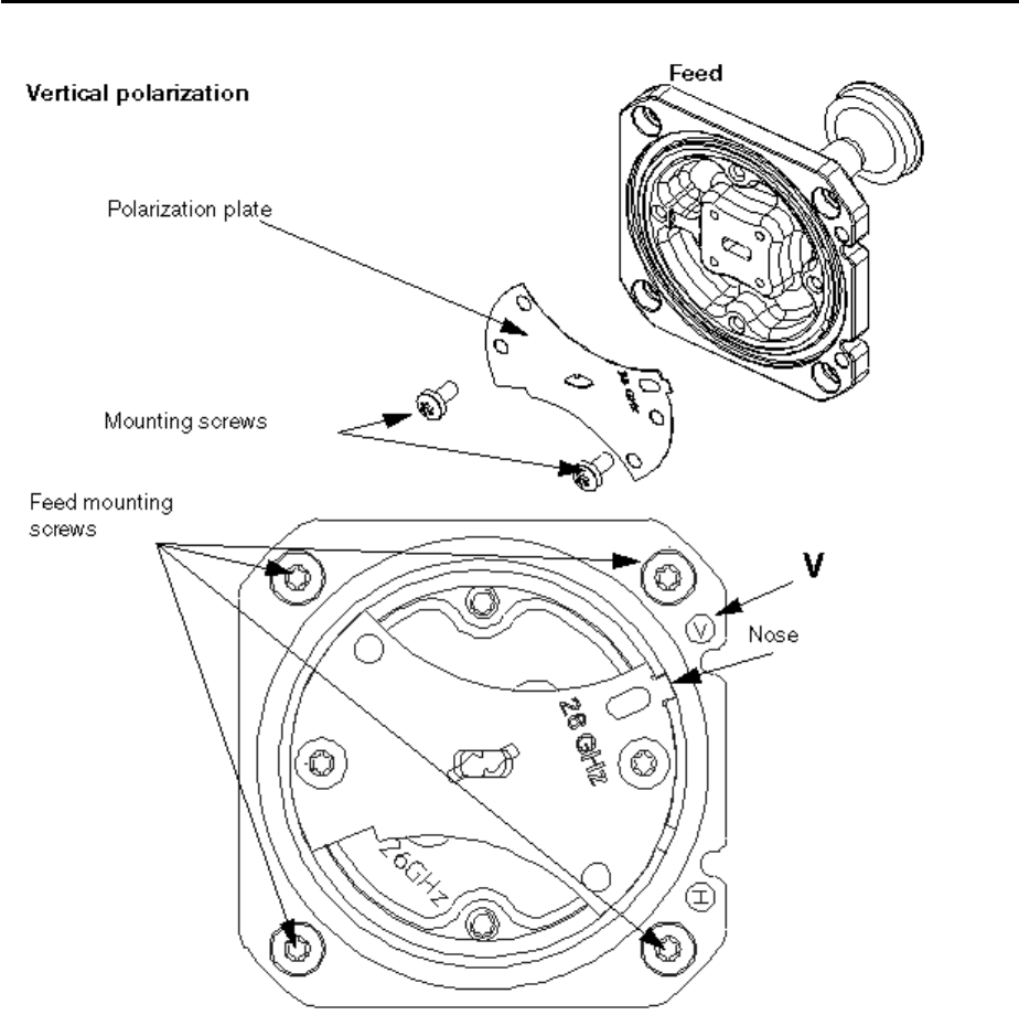
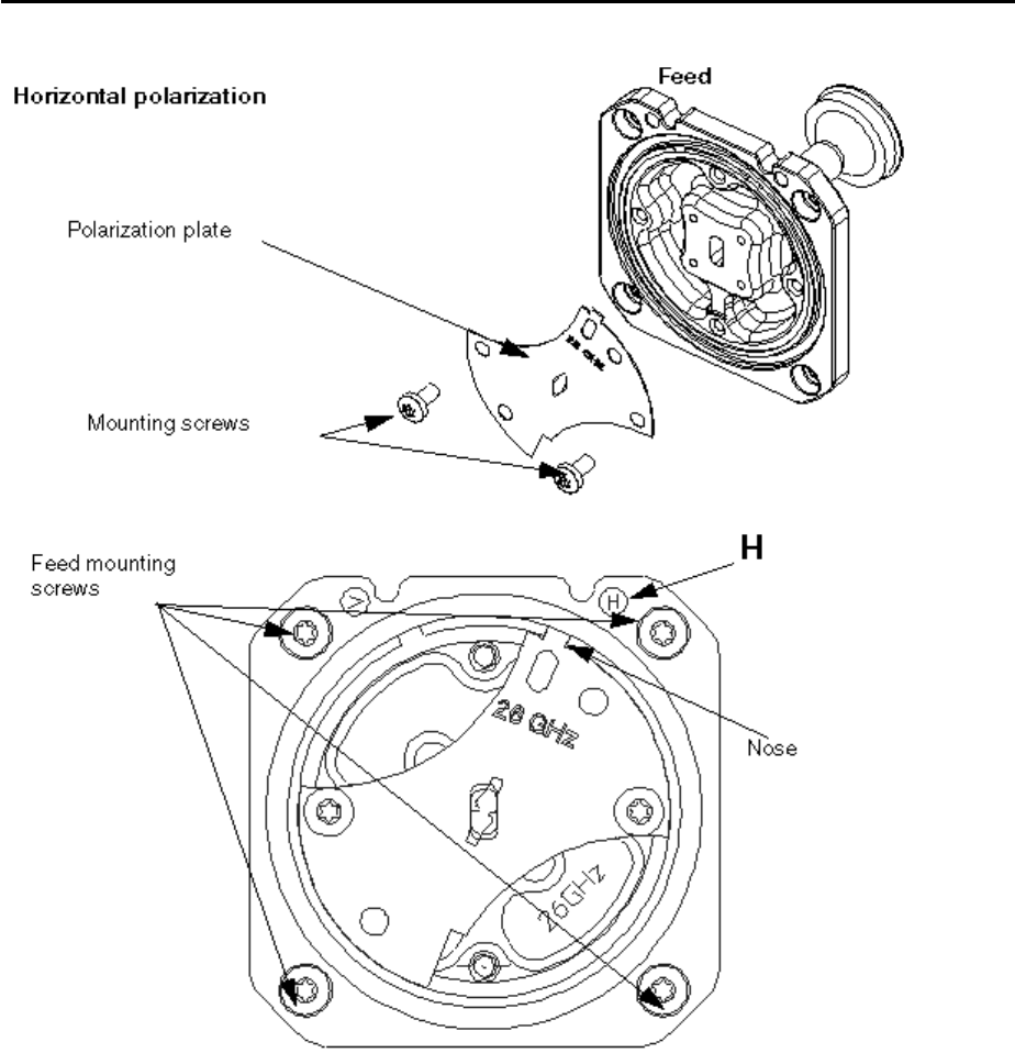
Figure 2-12 and Figure 2-13 shows the position of the polarization plate for
vertical and horizontal polarization.
To change the polarization, proceed as follows:
1. Loosen the four mounting screws of the feed. Then turn the feed to the
required position for a vertical or horizontal polarization.
2. Retighten the feed by means of the four mounting screws
(Torque: 190 Ncm).
3. Loosen the mounting screws of the polarization plate.
4. Remove the polarization plate.
5. Remount the polarization plate in the correct position for the required
polarization. The nose of the polarization plate must point to H or V.
6. Secure the polarization plate by means of its mounting screws
(torque: 190 Ncm).
Page 23 Proprietary Information Marconi
Doc number 05PHAxxxxxyyy Fehler! Verweisquelle konnte nicht gefunden werden.
Version: DRAFT Mounting the Outdoor Units
Figure 2-12 Adjusting the vertical polarization
Page 24 Proprietary Information Marconi
Doc number 05PHAxxxxxyyy Fehler! Verweisquelle konnte nicht gefunden werden.
Version: DRAFT Mounting the Outdoor Units
Page 25 Proprietary Information Marconi
Figure 2-13 Adjusting the horizontal polarization