Marelli Europe S p A 503-00-154 Vehicle Immobilizer User Manual 500 00 154 descrizione prodotto en
Magneti Marelli S.p.A. Vehicle Immobilizer 500 00 154 descrizione prodotto en
Users Manual

SITEMI ELETTRONICI
503.00.154
Page 1 of 3
Version 0 06.06.2007
Product description
and
Technical specification
Type
503.00.154
Panel instrument with integrated immobiliser for
VW group application
Abstract
This document summaries the technical characteristics of the device providing information
of both a specific and a general nature.

SITEMI ELETTRONICI
503.00.154
Page 1 of 3
Version 0 06.06.2007
1. Main Performance
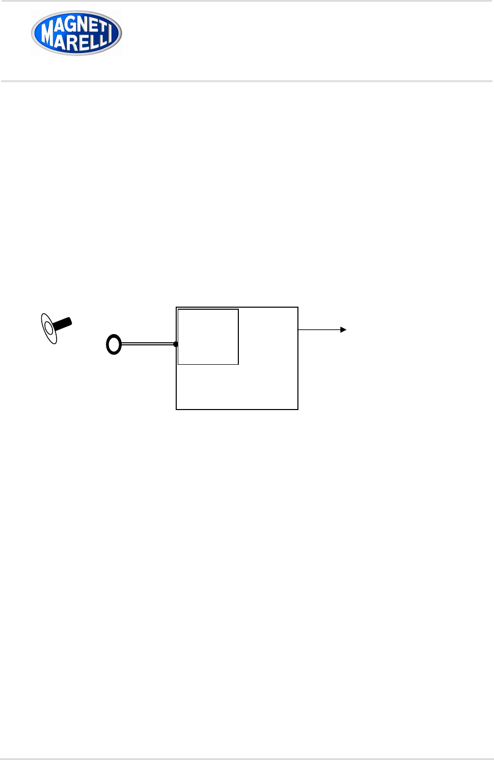
The Immobilizer built in the instrument panel has to read out the data code from a Transponder, located
inside the key, and checks whether that key is authorized to start the engine of the vehicle.
In case of an authorized key, a start-enable code is sent to the requested Engine Management System
(EMS) via CAN-line. Else, the starting of the engine is disabled by sending a negative answer to the request
of the EMS.
2. System Components
2.1 Transponder inside key
The Transponder is composed of a receiver/transmitter coil and an electronic circuit, featuring rectifier,
voltage regulator, sequencer and memory. The Transponder is power-supplied by means of the 125kHz
electro-magnetic field. The Crypt-(security)-Transponder is based on a bidirectional communication
(amplitude modulation and demodulation).
2.2 Transmitter/Receiver coil (Antenna) at the ignition lock
The Antenna supplies the transponder with energy, sends commands and data to the Transponder and
receives codes from the transponder.
2.3 Immobilizer part of the instrument panel
The Immobilizer unit of the instrument panel is directly connected to the Immobilizer Antenna and stores the
authorised key codes in a non-volatile memory. The instrument panel is permanently supplied with battery
voltage (KL30). The Immobilizer function operates with ignition (KL15) on.
3. Normal Starting Sequence
1. Initialize the immobilizer function of the immobiliser built in the instrument panel at the key on
(ignition, KL15 on)
2. The 125kHz electromagnetic field is switched on
3. The Immobilizer read out the fixcode of the Transponder
4. If the fixcode is recognized a bidirectional authentication protocol is proceeded with the engine
control unit (max. 300ms)
5. The received authentication code is verified
6. If the verification procedure is passed , wait for request from engine control unit

SITEMI ELETTRONICI
503.00.154
Page 1 of 3
Version 0 06.06.2007
4. Pinning of the instrument panel with immobilizer unit
P13-7 coil
P13-8 coil
P13-12 CAN (H)
P13-13 CAN (L)
P13-1 Ignition key (KL15)
P13-2 Battery Voltage (KL30)
P13-19 GND
Block diagram for the instrument panel with immobilizer unit
6. Electric specification’s
Clock frequency : 32 MHz
Power supply : 13,5V (vehicle battery)
Foundmental immobiliser frequency : 125 kHz
Antenna coil loop number : 131
Resistance : 40Ω @ 25°C 1kHz
Inductance : 1,613 mH @25°C 1kHz
Antenna for
Immobilizer
Instrument panel
Key with
Transponder
Immo-
bilizer
unit
To ECU