Marelli Europe S p A MFDPCC Car Radio with Bluetooth Transceiver User Manual
Magneti Marelli S.p.A. Car Radio with Bluetooth Transceiver
Users Manual

PACCAR Display
DRAFT 10/7/2010 12:03 PM Y53-6035 Page 1 of 30
INTRODUCTION
This manual describes the vehicle’s
interactive system located on your
dashboard.
SAFETY
In this operator manual
A number of alerting messages are in
this manual. Please read and follow
them. They are there for your
protection and information. These
messages can help you avoid injury to
yourself and others, as well as prevent
costly damages to the vehicle.
Key symbols and “signal words” are
used to indicate what kind of message
is going to follow. Pay special attention
to instructions prefaced by symbols
and the signal words “WARNING”,
“CAUTION”, and “NOTE”. Please do
not ignore any of these alerts.
WARNING
When you see this word, the message
that follows is especially vital. It signals
a potentially hazardous situation which,
if not avoided, could result in an injury
or death. This message will tell you
what the hazard is, what can happen if
you don't heed the warning, and how to
avoid it.
Example:
Never carry additional fuel containers
in the vehicle. Such containers, full or
empty, may leak, explode or cause a
fire in the event of a collision.
CAUTION
Signals a potentially hazardous
situation which, if not avoided, could
result in property or vehicle damage.
Example:
Continuing to operate your vehicle with
insufficient oil pressure will cause
serious engine damage.
NOTE
Provides general information: for
example, the note may suggest how to
operate the vehicle more efficiently.
Example:
Pumping the accelerator will not assist
in starting the engine.
Please take the time to read these
messages when you see them, and
remember:
WARNING Something that
could seriously injure or kill you
or others.
CAUTION Something that
could cause property or vehicle
damage.
NOTE Useful information.
General safety reminders
Certain functions are restricted to
operate only when the vehicle is

PACCAR Display
DRAFT 10/7/2010 12:03 PM Y53-6035 Page 2 of 30
stationary for your safety and the safety
of those not in the vehicle.
Safe driving is only possible with the
proper concentration on the driving
task. Keep distraction to a minimum to
improve your concentration. Examples
of distractions may include radio
controls, GPS navigation controls, cel-
lular telephone calls, cellular text
messages, reading or reaching for
something on the floor. Minimizing
your distractions will improve safe
driving and will help avoid an accident
involving death or personal injury.
WARNING: Only glance at the
display monitor while driving.
Prolonged periods of viewing while
driving could result in an accident
and death or possible personal
injury.
WARNING: Do not program the
System while driving. Always stop
your vehicle when programming or
changing the settings on the
System. Programming the system
while driving can cause you to take
your eyes off the road, which could
result in an accident. Failure to do
so could lead to death, serious
injury or equipment damage.
CAUTION: Do not rely on the
Navigation System to route you to the
closest emergency services. Not all
emergency services are in the
database.
NOTE: Regardless of how and where
the navigation system directs you, it is
your responsibility to operate the
vehicle in a safe and legal manner.
NOTE: Ensure the volume level of all
audio devices is set to a level that still
allows you to hear outside traffic and
emergency vehicles.
FCC Statement
This device complies with Part 15 of
the FCC rules subject to the
following two conditions:
This device may not cause
harmful interference.
This device must accept all
interference received,
including interference that may
cause undesired operation.
Changes or modifications not
expressly approved by the
party responsible for
compliance could void the
user’s authority to operate the
equipment
Dear customer, to ensure a healthy
RF exposure please keep a distance
of at least 20 cm from the device.
For any other request regarding RF
exposure compliance in Canada,
please refer to our local
representative:
Renaissance Consulting
11 Parsons Ridge Road,
Kanata, Ottawa
Ontario, Canada, K2L 2M1
PACCAR Display
DRAFT 10/7/2010 12:03 PM Y53-6035 Page 3 of 30
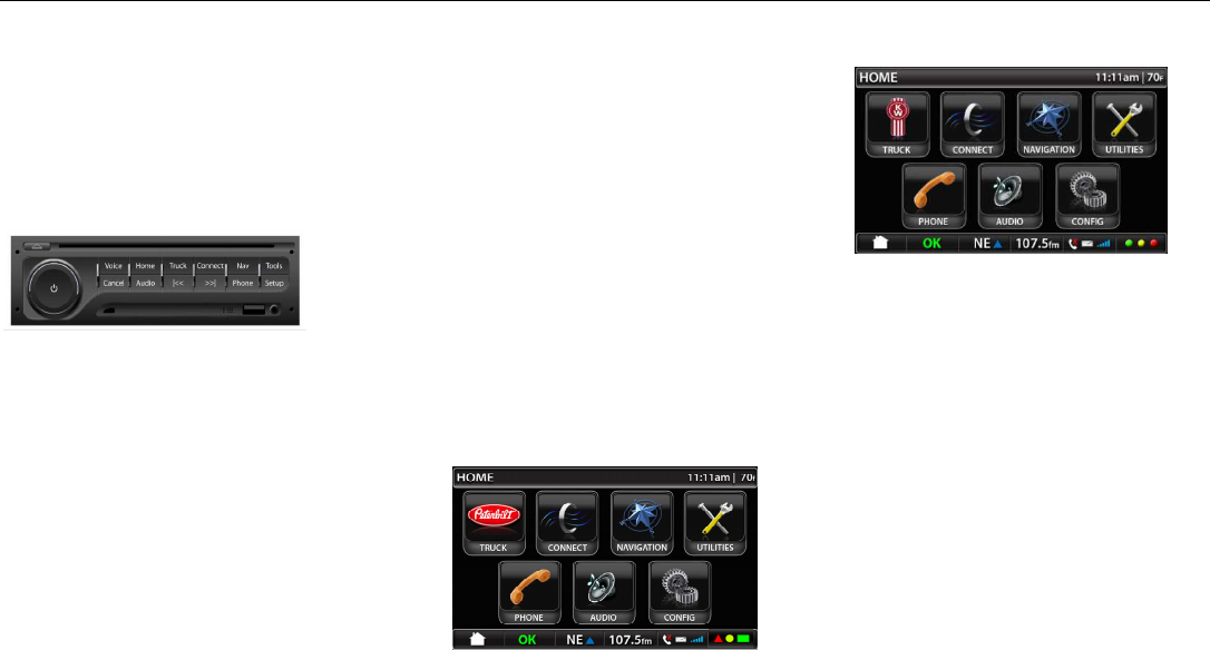
Description
The system is comprised of a remote
head unit and a display screen. The
remote head unit will be located in the
instrument panel and disassociated
from the display.
Image 1 – Remote Head Unit
The following buttons, knobs and
connectors are on the face of the head
unit • Power Button
• Volume Knob
• Eject Button
• Voice Button
• Home Button
• Truck Button
• Connect Button
• Nav Button
• Tools Button
• Cancel Button
• Audio Button
• RWD Button
• FWD Button
• Phone Button
• Setup Button
• USB jack
• 3.5 AUX jack
The buttons will be referred to as hard
keys or hard buttons in the rest of this
specification. The keys on the touch
screen will be referred to as soft keys
or soft buttons.
Image 10 - PB Main Menu
Image 11 – KW Main Menu
The display has three general areas for
information and interaction.
Center
The center of the display will have the
available functions and information for
the operator.
Title bar
The ‘Title Bar’ is placed at the very top
of the display. Not every screen will
have the title bar visible due to
graphics requirements of some third
PACCAR Display
DRAFT 10/7/2010 12:03 PM Y53-6035 Page 4 of 30
party applications. This will be noted in
the appropriate sections of the
document.
Image 6 – Title Bar Examples
Quick Jump Bar
The ‘Quick Jump Bar’ is placed at the
very bottom of the display.
Image 8 – Screen Bottom Example
How to care for your screen
1. QUICK SETUP
Before using the system for the first
time, you may need to program the
system for the home location, setup
any pairing devices or decide what
virtual gauges you want to display.
Set up home location
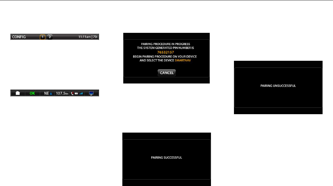
Pair a Bluetooth device
Image 81 – Adding Device Screen
The notation for SmartNav will be
replaced with NavPlus for Kenworth
devices.
Image 82 – Pairing Successful
Notification
Once the target device is paired, it will
take the user back to the Bluetooth
main screen (ref. image 80).
Image 83 – Pairing Unsuccessful
Notification
If the target device fails to pair, it will
take the user back to the Bluetooth
main screen (ref. image 80).
Program address book
PACCAR Display
DRAFT 10/7/2010 12:03 PM Y53-6035 Page 5 of 30
Virtual gauges
OPERATING THE
SYSTEM
The PACCAR Display shall operate in
two distinct modes for the purposes of
mitigating driver distraction. All
screens and features are functional
when the vehicle is stationary. While
moving, only certain screens will be
functional. The restricted functions are
visible as grey icons to let the operator
know that they are not functioning while
the vehicle is in motion. For example,
the system will allow a destination
location to be programmed while the
vehicle is in motion but will not allow
the home location to be programmed
while the vehicle is in motion.
NOTE: Camera – If the user setting for
camera is set to automatic,
then the cameras can
automatically function as
defined. If the user setting is
set to manual, the user would
have to go the Camera sub-
menu to view camera and
select from multiple installed
cameras.
Hands-Free Calling – The system shall
show the screens per the ASR tree
(section 9) but there shall be no touch
interaction with the screens – buttons
greyed out. When the call ends the
device will remain in the phone home
screen per the ASR tree. Upon the first
time the PACCAR Display is powered
on in a vehicle it will default to the
‘Home Menu’ screen. After all
subsequent power on events, the
PACCAR Display will automatically
launch into the screen/mode that was
last active during the previous power
down event.
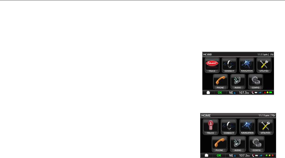
The PACCAR Home Menu screen
consists of the following:
<TRUCK> - Vehicle monitoring
functions (shows a Peterbilt or
Kenworth logo)
<CONNECT> – Model based
functions
<NAVIGATION>
<TOOLS> - Tools for the user
<PHONE>
<AUDIO>
<SETUP> - Setup of the system
Image 10 - PB Main Menu
PACCAR Display
DRAFT 10/7/2010 12:03 PM Y53-6035 Page 6 of 30
Image 11 – KW Main Menu
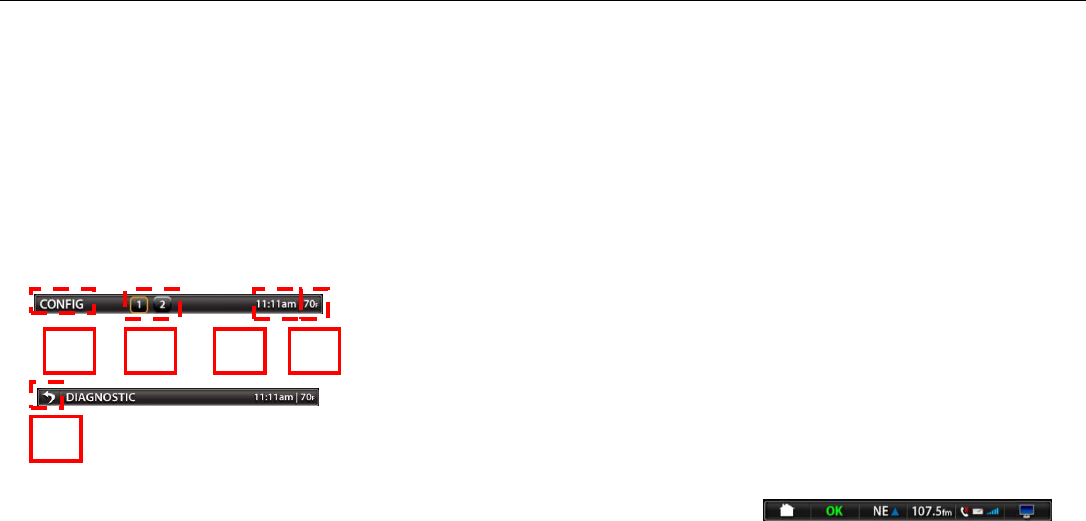
Title Bar
The ‘Title Bar’ is placed at the very top
of the display. Not every screen will
have the title bar visible due to
graphics requirements of some third
party applications. This will be noted in
the appropriate sections of the
document.
Image 6 – Title Bar Examples
The following items will be shown on
the ‘Title Bar’
1 – Identification of Screen/Function
The screen/function identification is
simply the screen the user is currently
in and is shown in subsequent sections
by image examples.
2 – Available Screen Pages
The screen pages serve the purpose of
notifying the user if multiple pages are
available in each menu and also
function as soft keys to select different
menu pages. This feature is only
available on menus where more than
one page is available.
3 – Time
The time display simply displays the
current system time. Settings are
defined in section 7.11.4.
4 – Temperature
The temperature display displays the
outside temperature as received from
the vehicle CAN. Settings are defined
in section 7.11.5.
5 – Back Button
The back button is a tool to allow the
user to go back up one level in the
menu structure. The back button is
only visible when the device is in a
lower sub menu. It will not be available
on the home screen or next level
menus where simply pressing the
home button will take the user back to
the previous screen.
Quick Jump Bar
The ‘Quick Jump Bar’ is placed at the
very bottom of the display. The font on
the ‘Quick Jump Bar’ is called out
further below.
Image 8 – Screen Bottom Example
1 2
5
3 4
PACCAR Display
DRAFT 10/7/2010 12:03 PM Y53-6035 Page 7 of 30
The following items will be shown on
the ‘Quick Jump Status Bar’
• <HOME MENU> soft button
• <VEHICLE STATUS
MONITOR> soft button
• <AUDIO MONITOR> soft
button
• <PHONE INDICATOR> and
soft button
• <DISPLAY SETTINGS> soft
button
Image 9 – Screen Bottom Detail
1 - The Home Menu
soft button is active on
all screens except for the Home Menu
screen. This graphic will be set to 70%
transparency and be rendered inactive
on the Home Menu screen. For all
other screen, the Home Menu icon will
be 100% opaque. Pressing the Home
Menu button returns the user to the
Home Menu.
2 - The ‘Vehicle Status
Monitor’ will display an
overall status message
for the vehicle systems the PACCAR
Display is monitoring.
A vibrantly colored green ‘OK’ icon is
displayed when all PACCAR Display
monitored vehicle systems are running
within specification. The Vehicle
Status Monitor button is rendered
inactive as no PACCAR Display
monitored vehicle systems require
monitoring by the operator.
Should a PACCAR Display monitored
vehicle system go out of specification,
the ‘OK’ graphic will change to a
vibrantly colored ‘!” warning icon.
The Vehicle Status Monitor soft button
will become active upon an PACCAR
Display detection of an out of
specification vehicle condition and is
kept active for as long as the out of
specification condition exists.
If only one ‘out of specification’ vehicle
condition exists, the PACCAR Display
will take the user directly to the specific
screen which will display the out of
specification information upon selection
of the Vehicle Status Monitor soft key.
Should more than one out of
specification condition exist when the
user selects the Vehicle Status Monitor
soft button, the PACCAR Display will
go to the ‘Faults Screen’ where all
PACCAR Display monitored out of
specification conditions will be listed.
The user will then select which fault he
or she wants to monitor further.
The Vehicle Status Monitor will be
detailed further in the ‘Fault Monitoring’
section of this document.
1 2 3 4 6 5

PACCAR Display
DRAFT 10/7/2010 12:03 PM Y53-6035 Page 8 of 30
3 - Navigation Monitor and Soft Button
(see section 7.7)
The navigation button allows the user
to go easily to the navigation
environment. The button shows the
compass heading the vehicle is
traveling: N, S, E, W, NE, NW, SE,
SW.
4 - Audio Monitor and Soft Button (see
secton 7.10)
The audio mode and audio
identification will be shown in this
section of the Quick Jump Status Bar.
Selecting the Audio Monitor soft button
will take the user directly to the display
screen of the currently active audio
source. The band will be listed as 24
point.
The audio modes that will be shown
are (depending on which mode was
last selected)
• Station frequency
• CD/USB/BT Track #
• Satellite station number
• Aux input
5 – Phone Button (see section 7.9)
If no phone is connected, phone is
greyed out. The red X shows up only if
a call is missed on Bluetooth
connected phone.
The envelope is greyed out if no text
message is received on Bluetooth
connected phone.
Cellular strength is only for optional
external modem, not Bluetooth
connected phone. This will be grayed
out if there is no modem or modem has
no signal strength.
6 – Display Settings
Soft Button (see
section 7.11)
The Display Settings soft button is
active on all screens. Selection of this
soft button will open up the ‘Display
Settings’ pop up window overlay on
any active screen. The programming
should support the future addition of a
Qualcomm green/yellow/red indicator
to take the place of the display button if
the vehicle is equipped with Qualcomm
MCP200 (Qualcomm functionality will
not be supported at product launch).
Truck Menu
The truck menu will host the vehicle
monitoring functions of the PACCAR
Display. Five vehicle monitoring
features are required at product launch
• Gauges
• Hybrid Mode (if equipped)
• Warnings
• Diagnostic Messages
• Camera
Image 12 – PB Truck Menu
PACCAR Display
DRAFT 10/7/2010 12:03 PM Y53-6035 Page 9 of 30
Image 13 – PB Hybrid Vehicle Menu
Image 14 – KW Truck Menu
Image 15 – KW Hybrid Truck
Gauges
Selecting the <GAUGES> soft button,
the screen will change to the virtual
gauge view. Please refer to the
vehicle’s operator manual for a
complete description of each gauge.
PACCAR Display
DRAFT 10/7/2010 12:03 PM Y53-6035 Page 10 of 30
Image 19 – PB Virtual Gauges
(Standard)
PB % Horsepower Gauge
This is engine flywheel horsepower,
calculated from torque and RPM
information from the engine computer.
PB % Torque Gauge
This is engine flywheel torque,
calculated from torque and RPM
information from the engine computer.
PB Idle Time Gauge
Show accumulated idle time elapsed
as reported by vehicle in Minutes
PB Idle Fuel Gauge
Show accumulated idle fuel burned as
reported by vehicle as whole digits with
no decimal places
PB Fuel Rate Gauge
Show current fuel flow rate reported by
vehicle as whole digits with no decimal
places
Hybrid Display
Pressing the Hybrid soft button will
launch the Hybrid monitoring
environment.
PACCAR Display
DRAFT 10/7/2010 12:03 PM Y53-6035 Page 11 of 30
When in the Hybrid monitoring
environment, the screens shown below
would consume the main screen area
in addition to the top bar area. The
bottom bar menu shall be maintained.
The screens have no touch screen
functionality or interaction. Only the
bottom bar will maintain the touch
control.
Please refer to Operator’s Manual
Supplement Y53-6031 for more details
about the hybrid display.
Diagnostic Messages
Image 36 – Diagnostic Message
Home Screen
The truck diagnostic screen will be
populated with active messages from
the following systems:
• Engine
• Engine Aftertreatment System
• Transmission
• Instrumentation System
• Anti-Lock Braking System (ABS)
• PACCAR Display Internal
Diagnostics
The messages will populate as long as
the fault remains published from the
system source. Once the fault is no
longer published, the message will be
removed from the screen. The
possible faults are listed in Appendix I.
The Diagnostic Message Home Screen
(Image 36) will show a maximum of 5
messages per screen and can be
paged up or down using the soft key
arrows on the right hand side of the
screen. Once a message is selected,
the system will go to the Diagnostic
Detail Screen (Image 37).
The <PAGE UP> and <PAGE DOWN>
soft button arrows on the right hand
side of the screen will be grayed out
unless the number of messages
require their use to page up or down
the list.
This feature is merely to show the user
the published diagnostic messages on
the vehicle and cannot be used as a
method to clear them. Clearing
messages will still have to be
accomplished via each publishing
systems diagnostic clearing processes.
PACCAR Display
DRAFT 10/7/2010 12:03 PM Y53-6035 Page 12 of 30
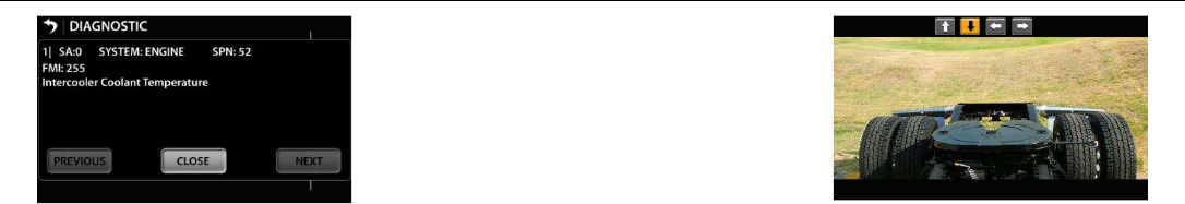
Image 37 – Truck Diagnostic Detail
Screen
The Diagnostic Detail Screen will give
more information on a selected
diagnostic message. The items
displayed include:
• Source Address
• Source of Diagnostic Code
• SPN
• FMI
• Text Description of Code
The user can page to a previous
message (if applicable) or next
message (if applicable) by selecting the
soft buttons at the bottom of the
screen.
The user can press the <CLOSE> soft
button at the bottom of the screen to
return to the Truck Diagnostic Home
Screen.
Cameras (Optional)
Cameras (when connected to video
input 1-4 in the head unit) can be
viewed in the display in two modes:
Automatic and Manual.
In the automatic mode, the cameras
are identified by the arrow keys. The
arrow keys indicate what direction the
operator wants to see.
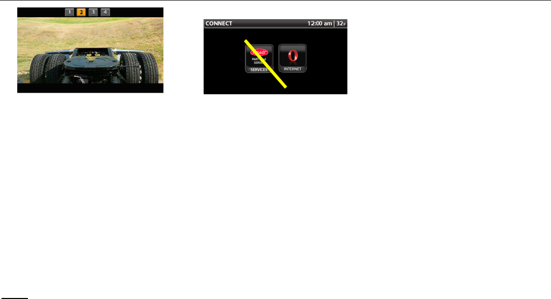
Image 38 – Automatic Camera Mode
(Image Example Only)
In the manual mode, the cameras are
identified by numbers. The number
icons 1-4 at the top of the screen
correspond with the camera that are
installed to video inputs 1-4 in the head
unit and are also soft buttons to select
different camera inputs These
numbers may or may not correspond to
any direction that the camera is
installed in.
PACCAR Display
DRAFT 10/7/2010 12:03 PM Y53-6035 Page 13 of 30
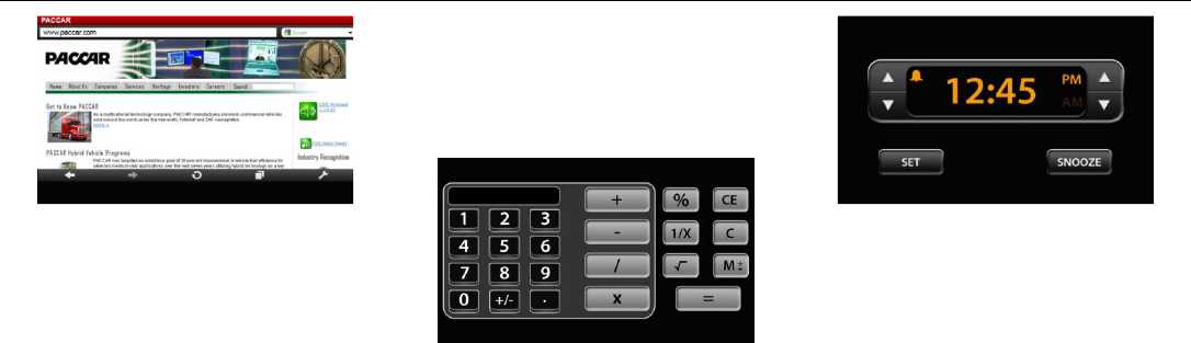
Image 39 – Manual Camera Mode
(Image Example Only)
The screen will be blank with the
number icons 1-4 at the top of the
screen for any cameras that are not
installed.
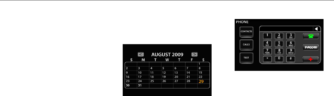
Connect
Connectivity and telematics
functionality will be found under the
Connect menu. Services and Internet
function keys will be present at launch.
These functions require a modem and
active subscription with a wireless
carrier (Sprint-US at launch).
Image 45 - Internet Default
Website Screen
Services and Internet features are
dependent on an external modem
connected to the PACCAR Display and
wireless communication service being
active.
Connection Manager
HMI for the Connection Manager shall
be similar to the FWS’s HMI with the
look and feel of the PACCAR Display.
Supplier and Sprint (US CDMA Carrier)
and Bell Canada (Canada CDMA
Carrier) will jointly develop the HMI.
Final design must be reviewed and
approved by PACCAR.
Sprint’s PACCAR Dedicated Phone #:
877-301-9874
Sprint’s PACCAR Dedicated URL:
TBD.
Bell Canada’s PACCAR Dedicated
Phone #: TBD
Bell Canada’s PACCAR Dedicated
URL: TBD.
Internet
Internet browsing is accomplished via
the Opera browser. Selecting the
Opera button on the Connect Menu
Screen (Image 40) will launch the
browser.
PACCAR Display
DRAFT 10/7/2010 12:03 PM Y53-6035 Page 14 of 30
Image 48 – Opera Browser Screen
The browser can occupy the main area
of the screen and the top bar area but
the bottom bar shall be maintained.
Tools
The Tools menu houses productivity
tools for the vehicle operator.
The following tools will be made
available
• Calculator
• Alarm Clock
• Video Player
• Calendar
Calculator
The Calculator function is a tool to
perform quick computations.
Image 51 – Calculator Screen
Alarm
Selecting the Alarm soft button opens
up the alarm clock function. The
operator can set the alarm and pick an
audio source/noise to play at the
designated time. The Alarm will only
provide for one alarm setting.
Image 52 – Alarm Screen
The alarm shall activate the PACCAR
Display if it is in sleep mode when it is
time for the alarm to sound.
The <↑> and <↓> soft keys on the left
hand side of the screen are used to set
the hour as the hour advances past 12,
the AM to PM transition will happen the
same hold true if the hours are
decreasing and go from 1 to 12 in the
downward direction. The <↑> and <↓>
soft keys on the right hand side of the
screen are used to set the minutes
advancing the minutes over 59 or
PACCAR Display
DRAFT 10/7/2010 12:03 PM Y53-6035 Page 15 of 30
decreasing below 1 do not affect the
hour setting.
Selecting the <SET> soft key sets the
alarm and the bell icon goes from 50%
intensity to full intensity. Selecting the
<SET> soft key again turns the alarm
off and the bell icon reduces back to
50% intensity.
Selecting the <SNOOZE> soft key will
gain the user X more minutes before
the next alarm.
Video
The video screen allows the user to
bring in video using the aux-in or usb
inputs on the front of the head unit.
When the video soft key is selected,
the screen will bring in video to the
main area of the screen. The top and
bottom bars will be maintained.
If no video signal is present from the
aux-in or usb inputs, the main area of
the screen will remain blacked out.
Calendar
Image 53 - Calendar
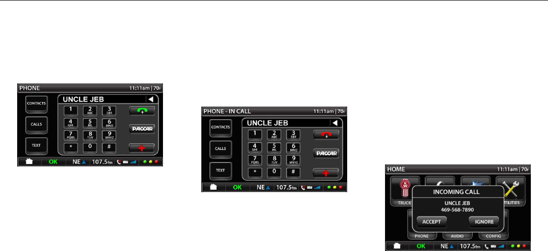
Phone
The Phone function provides the ability
for the user to place and receive calls
via a Bluetooth connected phone.
• Phone key pad
• Contacts
• Connect phone
• Call/Answer
• Hang up/Ignore
Image 54 – Phone Screen
The <PACCAR> soft key shall dial the
Peterbilt or Kenworth call center
depending on whether the device is a
Peterbilt or Kenworth. The call center
phone numbers are:
• Peterbilt Call Center: 1-800-
473-8372 (1-800-4-Peterbilt)
• Kenworth Call Center: 1-800-
592-7747 (1-800-KWASSIST)
PACCAR Display
DRAFT 10/7/2010 12:03 PM Y53-6035 Page 16 of 30
The emergency button (<RED
CROSS> in lower right half of screen)
shall be used to dial 911
Make Call
Image 55 – Make Call Screen
Phone number or contact shows up in
phone number field
User presses <GREEN PHONE> soft
key to make call
Phone turns red once dialing begins
PHONE title changes to PHONE – IN
CALL once dialing begins
Dialed call Contact/Number populates
CALLS → DIALED menu in PHONE
screen
In Call
Image 56 – In Call Screen
In CALL appears next to PHONE on
top bar.
Phone number or contact ID shows up
on the phone number field
Hang up icon is red
Press <HANG UP> soft key to end call
or <CANCEL> button on faceplate to
end call
Remaining phone buttons should be
rendered inactive while IN CALL
Any call received while IN CALL will
simply show missed call icon (‘X’) on
the bottom bar
Incoming Call
Image 57 – Incoming Call Popup
Incoming call popup with
<ACCEPT/IGNORE> option buttons

PACCAR Display
DRAFT 10/7/2010 12:03 PM Y53-6035 Page 17 of 30
Voice Recognition
Audio
The Audio screen gives the user
access to the entertainment audio
sources.
The audio sources are:
• AM/FM/WB
• CD
• Sirius Satellite Radio
• USB (including iPod)
• AUX
• Bluetooth audio streaming
device
If an audio source is not available, the
source soft button for that device will
be grayed out and rendered non-
functional. The soft button will activate
once the source becomes active.
Image 60 – Main Audio Screen
The audio main screen has selections
for:
• Band – FM/AM/WB
• Sirius – Satellite Radio
• CD
• USB – Memory Stick Input
• Aux – MP3 device input or
Ipod® input
• BT - Bluetooth® Paired Device
Input
Radio Band Select
Image 61 – Band Select
The band select screen allows the user
to select different control features of
the FM/AM/WB radio.
The first press of the <BAND> soft
button in the top left hand corner of the
audio main screen takes the user to the
band select screen. The screen will be
for the band last selected and the
default will be FM. By pressing the
<BAND> soft button again the user
can change audio bands in the

PACCAR Display
DRAFT 10/7/2010 12:03 PM Y53-6035 Page 18 of 30
following order: FM → AM → WB and
then starts over at FM.
The <SEEK↓> soft key allows the user
to select the next available station
down the band and the Seek↑ key
allows the user to advance to the next
available station up the band.
The <SCAN> soft key allows the user
to set the radio to automatically scan all
available stations by advancing up the
band until it reaches the end of the
band and then will start again at the
bottom of the band advancing upward.
The user can select a station by
pressing the <SCAN> soft key again.
The <TUNE↓> soft key allows the user
to manually tune down the dial while
the <TUNE↑> soft key allows the user
to manually tune up the dial. There is
no fast advancement by holding down
on either key.
The <PRESET> soft keys number 1-6
allow the user to store and access up
to 24 presets. The presets are divided
into four groups of 6 preset labeled 0-4.
Pressing on a <PRESET> soft key
takes the user to the assigned station.
The <PRESET SELECT> soft key
allows the user to select between
groups of presets and displays the
group currently available by the preset
keys. Example: PRESET 0 is the first
group of presets 1-6, PRESET 1 is the
next group of presets labeled 1-6 and
so on.
The information area shows what
preset the user is on, the station, the
band, and any station info that is
broadcast.
CD
Image 62 – CD
The CD screen is accessed by
pressing the <CD> soft key in the audio
main screen. The CD keys at the top
and bottom of the screen and
information on the CD inserted in the
middle of the screem.
When a CD is loaded the screen will
display the Artist Name, Album Title,
Song Title, Track Number out of Tracks
available (x/xx), and Time Elaspted.
The <RPT> soft key allows the user to
repeat the track.
PACCAR Display
DRAFT 10/7/2010 12:03 PM Y53-6035 Page 19 of 30
The <SHUF> soft key allows the user
to select shuffle play mode which
similates a random play order of the
available tracks on the CD.
The <GENRE> soft key allows the user
to page forward to the next genere of
music (if supported on the CD
information).
The <ARTIST> soft soft key allows the
user to page forward to the next artist
(if supported on the CD information).
Note: This feature is for CD’s that have
files loaded from numerous other
sources where the track maintains the
original artist information.
The <ALBUM> soft key allows the user
to page forward to the next album (if
supported on the CD information).
Note: This feature is for CD’s that have
files loaded from numerous other
albums where the track maintains the
original album information.
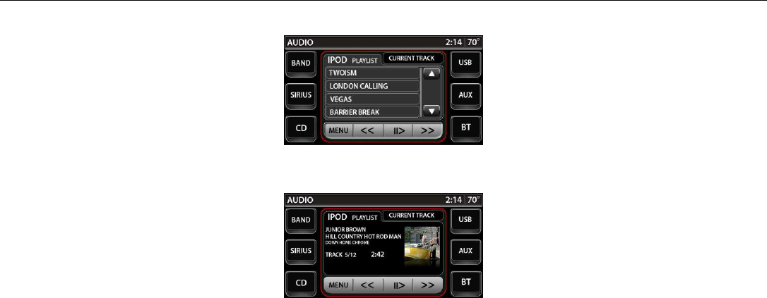
IPOD® Controls
Image 63 – IPOD Controls Screen
Image 64 – IPOD Playlist Control
The Ipod® controls screen allows the
user to access and play Ipod®
information when an Ipod® is
connected to the USB port.
The screen is intended to allow the
user to have similar controls available
to them on their Ipod®.
The <MENU> soft key allows the user
to access the menu in the same
manner as pressing the Menu portion
of their Ipod® control wheel.
The <UP> and <DOWN> arrows on the
right hand side of the screen allow the
user to move up and down the menu
list.
Selecting the menu line item on the
screen is the same as pressing the
select button in the center of the Ipod®
control wheel.
The <←←> soft key allows the user to
page backward in the playlist. The
<→→> allows the user to page forward
in the playlist.
PACCAR Display
DRAFT 10/7/2010 12:03 PM Y53-6035 Page 20 of 30
The <PAUSE/PLAY> soft key allows
the user to alternate between playing
an pausing the selected track.
The information screen displays the
Artist Name, Track Title, Album Title,
Track Number out of Tracks available
(x/xx), and Time Elapsed.
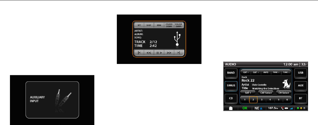
Aux Input
Image 65 – Aux In
By the user selecting the <AUX> soft
key from the audio main screen, the
system allows the operator to play
sound through their auxiliary system.
There is no control from the display for
this input device.
USB Input
Image 66 – USB In
In USB in mode the device will simply
play audio files in the MP3 format and
functions in the same manner as the
CD controls.
Bluetooth® Device Input
Selecting the <BT> soft key on the
audio main menu takes the user to the
Bluetooth® audio imput screen. The
screen functions similarly to the CD
screen in section. The screen only
displays information when a
Bluetooth® capable audio device has
been paired to the PACCAR Display.
(refer to QUICK SETUP) in this
manual.
Sirius
Selecting the <SIRIUS> soft key takes
the user to the Sirius Main Screen.
Image 67 – Sirius Main Screen
<CAT ↑> takes the user to the next
available category and <CAT ↓> on top
bar takes the user to the previously
available category.
<TUNE ↑> up takes the user to the
next available station and <TUNE ↓>
PACCAR Display
DRAFT 10/7/2010 12:03 PM Y53-6035 Page 21 of 30
on top bar takes the user t othe
previously available station.
<INFO> goes to the system information
screen below
Category text line added to audio
display text field – note “Rock” above
“Rock 22”
<CAT Select> takes user to Category
screen below (Image 68)
<CH Select> take user to Channel
Select screen below (Image 69)
Screen has 6 presets.
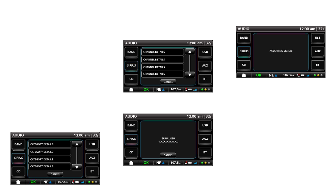
Image 68 – Sirius Category Select
Image 69 – Sirius Channel Select
Image 70 - Sirius Info
ESN screen is activated when the user
presses the information softkey on the
Sirius Main Screen.
Image 71 – Sirius Special Message
Special messages screen comes up
when the Sirius Mode needs to inform
user of status. The messages
available are:
• Acquiring Signal
• Antenna Error
• Channels Updating
• Firmware
PACCAR Display
DRAFT 10/7/2010 12:03 PM Y53-6035 Page 22 of 30
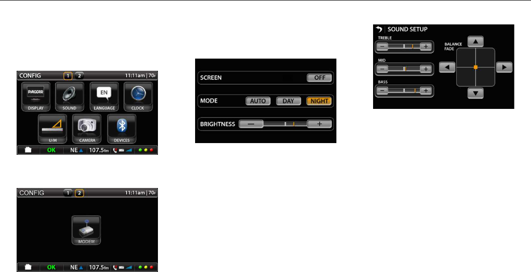
Setup
The Setup screen allows the user to
modify the product settings of the
PACCAR Display
Image 72 – First Setup Screen
Image 73 – Second Setup Screen
Display Setup
Image 74 – Display Setup
Within the display settings the screen
can be turned off, can be set to adjust
for daytime or nighttime display mode
and can be adjusted for brightness.
Turning the screen off will not turn off
the unit functionality. The screen will
light up to alert the operator of any
warning messages or incoming phone
calls.
Sound
Image 75 – Audio Setup
The sound setup screen allows the
user to adjust the audio settings of the
head unit. The settings are:
Treble – default is the median value
and allows to user to adjust to increase
using the <+> soft key and decrease
using the <–> soft key. The keys allow
for 10 incremental adjustments from
minimum to maximum.
Mid – default is the median value and
allows to user to adjust to increase
using the <+> key and decrease using
PACCAR Display
DRAFT 10/7/2010 12:03 PM Y53-6035 Page 23 of 30
the <–> soft key. The keys allow for 10
incremental adjustments from minimum
to maximum.
Bass – default is the median value and
allows to user to adjust to increase
using the <+> soft key and decrease
using the <–> soft key. The keys allow
for 10 incremental adjustments from
minimum to maximum.
The balance fade keys allow the user
to adjust the balance and fade of the
system while also receiveing a visual
feedback on the “center” of the audio
image. Pushing the <↓> arrow biases
the system towards the rear of the
vehicle while pressing the <↑> arrow
biases the system towards the front of
the vehicle. The buttons allow for 20
incremental adjustments from front to
rear.
Pressing the <←> arrow biases the
system towards the left hand side of
the vehicle (North American driver’s
side) whicle pressing the <→> arrow
biases the system towards the right
hand side of the vehicle (North
American passenger’s side). The
buttons allow for 20 incremental
adjustments from left to right.
All of the halos and buttons remain
default grey. The buttons will have an
amber halo while being selected but
will return to a default grey halo when
not selected.
The buttons in this menu only react
when they are touched. There is no
hold-down capability.
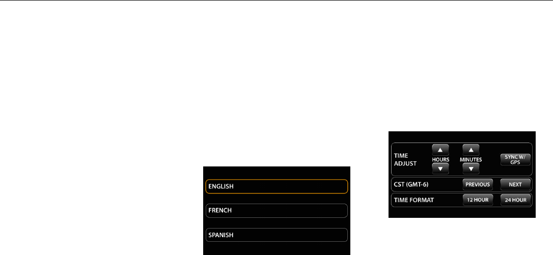
Language
Image 76 – Language Setup Screen
The language setup screen allows the
user to change the system language.
The language translation is defined in
Appendix 10.4 Language Translations
(except for the Garmin Navigation
environment).
The language setting that is currently
active will have the halo illuminated in
amber. The non-active settings will
have a default grey halo.
Clock
Image 77 – Clock Setup Screen

PACCAR Display
DRAFT 10/7/2010 12:03 PM Y53-6035 Page 24 of 30
Unit of Measure
Image 78 – Unit of Measure Setup
Screen
The units of measure can be changed
by the user such that any visible or
reported units of measure are affected.
Unit calculation and source information
from the vehicle cannot be changed in
this mode.
Camera
Image 79 – Camera Setup Screen
The Camera setup screen allows the
user to select between two modes:
Automatic Mode when selected allows
the user to have their cameras pre-
configured per Section 7.5.5:
Automatic mode also allows the user to
turn <ON> or <OFF> the auto reverse
camera.
Manual Mode allows the driver to
toggle between cameras by soft-key
press on the top of the screen as a
means to select the camera they want
to view (for functionality see section
7.5.5).
The user shall only be able to select
either Automatic or Manual. The
selected mode shall have the halo
highlighted noted as “– ON”. The unit
not selected shall be noted as “– OFF”.
The setting that is currently active will
have the halo illuminated in amber.
The non-active setting will have a
default grey halo. The button that is
currently selected shall have an amber
appearance to it while the non-selected
button shall have the default grey.
PACCAR Display
DRAFT 10/7/2010 12:03 PM Y53-6035 Page 25 of 30
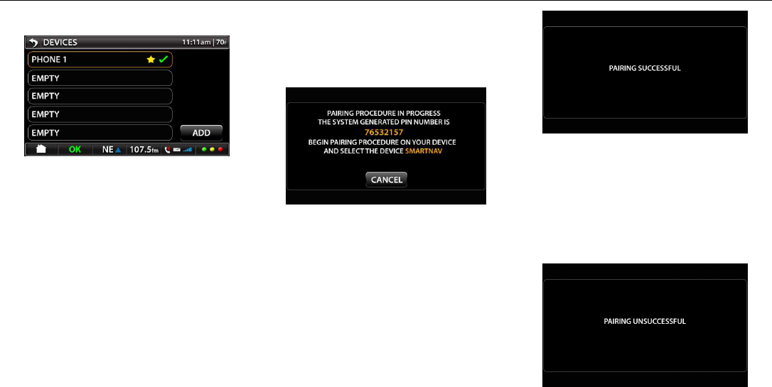
Bluetooth® Devices
Image 80 – Bluetooth® Main Screen
Favorite device indicated with star
Connected device indicated with green
check
Saved device ‘Phone 1’ box highlightes
upon selection and device options
window opens
Selecting <BACK> arrow returns user
to SETTINGS screen
The boxes that have phones paired to
them will have an amber halo. All
empty boxes shall have the defuault
grey halo.
Adding Device
Image 81 – Adding Device Screen
The notation for SmartNav will be
replaced with NavPlus for Kenworth
devices.
Image 82 – Pairing Successful
Notification
Once the target device is paired, it will
take the user back to the Bluetooth
main screen.
Image 83 – Pairing Unsuccessful
Notification
PACCAR Display
DRAFT 10/7/2010 12:03 PM Y53-6035 Page 26 of 30
If the target device fails to pair, it will
take the user back to the Bluetooth
main screen (ref. image 80).
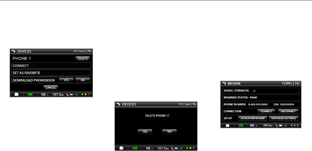
Options
Image 84 – Bluetooth® Options
Screen
Device name on top row with Delete
option
Connect, Set As Favorite, and
Download Phonebook need the halo to
be illuminated in amber or grayed out
as applicable.
In the Download Phonebook selection,
either the yes or no key needs to be
highlighted in amber depending on
which mode is selected. The non
selected button will remain default
grey.
Cancel button returns user to main
device screen
Selecting <BACK> arrow returns user
to CONFIG screen
Delete
Image 85 – Bluetooth® Delete
Screen
Selecting <YES> deletes device and
returns user to main BT devices screen
Selecting <NO> returns user to BT
devices options screen
Selecting <BACK>’ arrow returns user
to CONFIG screen
Modem
Image 86 – Modem Settings
SIGNAL STRENGTH: Field will be
blank if there is not signal.

PACCAR Display
DRAFT 10/7/2010 12:03 PM Y53-6035 Page 27 of 30
ROAMING STATUS: ROAM, HOME
or NO SERVICE (instead of “Error”)
PHONE NUMBER: Phone number
appears when device is activated.
Field will be blank if device is not
activated.
NOTE: It is a federal requirement to
display the phone number. Sprint
needs the Phone number and ESN #
when troubleshooting. To avoid
confusion for the user, Sprint will
include in the FAQ that this phone
number does not carry voice nor text
messaging functionality. This should
also be included in the PACCAR
Display Users Manual.
Phone Number = MDN (Mobile Device
Number) = MEID
ESN: ESN # from attached modem.
Field will be blank if modem is not
present.
CONNECTION: This feature may be
used to manually
CONNECT/DISCONNECT service
(assume service is activated).
If connected, the <CONNECT> soft
button will be grayed out.
If disconnected, <DISCONNECT> soft
button will be grayed out.
User may manually DISCONNECT to
avoid roaming to prevent unwanted
roaming charges.
Press <CONNECT> soft button
The system will connect to the wireless
network.
Press <DISCONNECT> soft button
The system will disconnect from the
wireless network.
NOTE: Sprint will include explanation
of this functionality in the FAQ. This
should also be included in the
PACCAR Display Users Manual.
SETUP:
Press <ACTIVATION WIZARD> soft
button
ACTIVATION WIZARD screen appears
Press <ADVANCED SETTINGS> soft
button
ADVANCED SETTINGS screen
appears
Image 87 – Modem Activation
Scenario 1: For Activated Modems
If the modem is already activated, the
<YES> and <NO> soft buttons will be
grayed out.
PACCAR Display
DRAFT 10/7/2010 12:03 PM Y53-6035 Page 28 of 30
Message says:
“Your modem has been
activated.”
Scenario 2: For Not Activated Modems
Message says:
“Your device is not activated.
Would you like to activate it?”
Press <YES> soft button.
The system runs an OMADM process.
If successful, message says:
“Activation completed
successfully.”
If failed, message for Sprint modem
says: For Kenworth device:
“Service update failed. Would
you like to try again?
If this problem persists, please
contact Sprint at 1-877-301-
9874 or visit
www.Sprint.com/NavPlus for
information about this service”
For Peterbilt device:
“Service update failed. Would
you like to try again?
If this problem persists, please
contact Sprint at 1-877-301-
9874 or visit
www.Sprint.com/SmartNav for
information about this service”
Press <NO> soft button
The screen returns to MODEM
screen
Press <CANCEL> soft button
The screen returns to MODEM
screen
PRL UPDATE: PRL =
Preferred Roaming List
(Verizon, T-Mobile, etc.)
Press <YES> soft button
System checks for updated
PRL and new network will be
pushed to the modem by
Sprint.
NOTE: An explanation needs
to be in the PACCAR Display
Users Manual and the FAQ on
what this is and why it would
be selected.
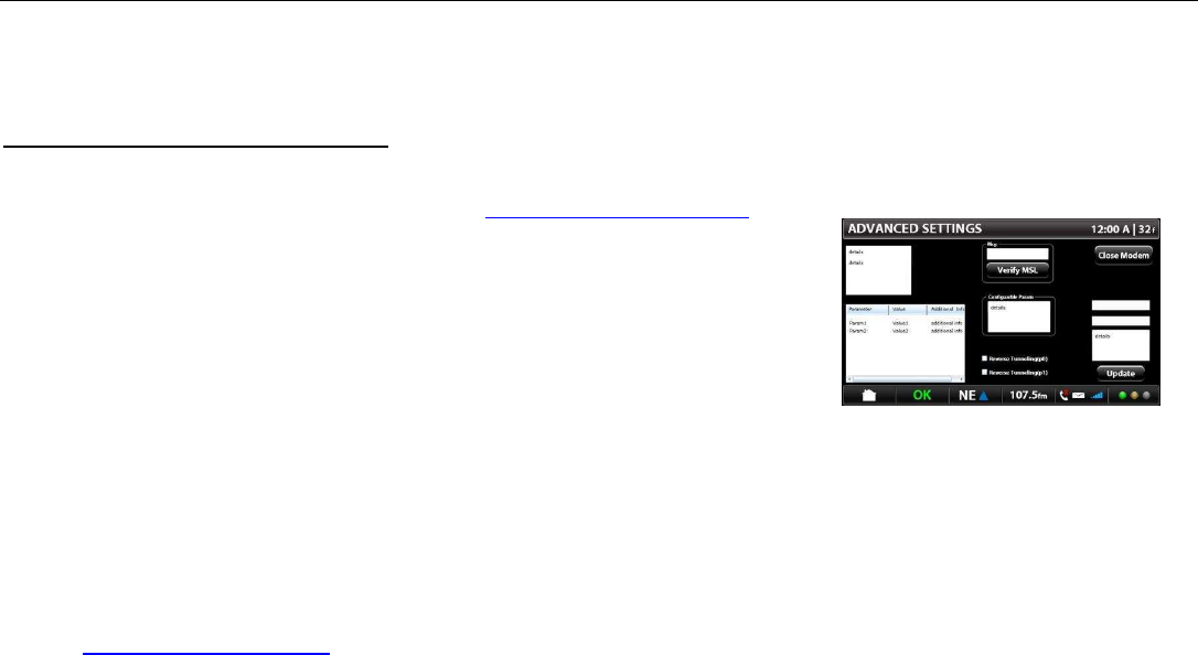
Image 88 – Advanced Settings
Screen
This is a Diagnostic screen for Sprint.
NOTE: Font size for the selectable
fields must be large enough for user to
select easily.
Upper Left Box:

PACCAR Display
DRAFT 10/7/2010 12:03 PM Y53-6035 Page 29 of 30
The selectable options are:
Modem Info
System Preferences
Connection & RF
Data Settings
Advanced
Factory Defaults
The values for the selected option will
appear in the Bottom Left Box.
The modem firmware version will be
display when Modem Info is selected.
In Configurable Parameters the
selectable options are based on valid
MSL: MDN
MSID
Home – SID & NID
When user selects one of the
Configurable Parameters options, two
text boxes and list box in the right side
will populate the respective data.
Press <UPDATE> button.
This will update any of those fields
above and is purely a diagnostician
step. The customer should never have
a need to go here without instruction
from a Sprint Tier 2 support person.
The <UPDATE> button will only be
active for certain configurable
parameters.
MSL Box:
MSL = Master Subsidiary Lock (Unlock
code; unique to ESN)
To perform manual activation:
1. Press the box above <VERIFY
MSL> soft button.
2. A keyboard will pop up.
3. Enter the MSL number and press <
VERIFY MSL> soft button.
4. The system will reach out to the
network and try to activate on the
network.
If MSL verifcation failed, a message
would appear. “Failed”
If the “Verify MSL” is successful, the
configurable fields will be filled in.
If failed, a message would appear.
“Failed”
If <VERIFY MSL> button is not
pressed, user will not be able to do
anything on this screen.
Reverse Tunneling: These check
boxes should not be used by
customers unless directed.
MEID and MSID will be populated in
the filed boxes directly right to the field
where they will show up in the dialogue
boxes below MSL field once the MSL is
correctly entered. This is a Tier 2
support activity.
Press <CANCEL> soft button.
The screen returns to MODEM screen
PACCAR Display
DRAFT 10/7/2010 12:03 PM Y53-6035 Page 30 of 30
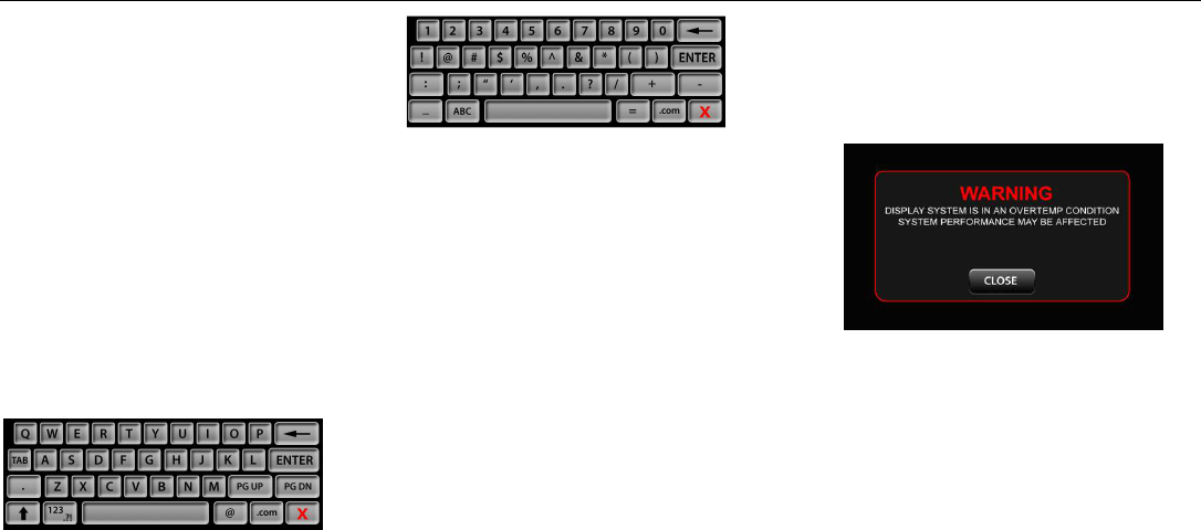
Keyboard
The display has a keyboard available in
the following screens:
• Phone Text Message
• Navigation
• Internet Browser
There are two keyboards available:
Alpha and Symbol Charactors pressing
in an area that needs text entered. The
user can toggle between the two
keyboards by selecting the keyboard
selector toggle key.
Image 91 – Alpha Characters
Image 92 – Symbol Charactors
The user enters the keyboard mode by
selecting a botton on the screen that
says keyboard or when selecting an
area that need text entry.
The keyboard overlays the bottom
portion of the screen such that the user
can see what they are typing in the top
half.
Pressing the red <X> on the keyboard
allows the user to exit the keyboard
and it will disappear from view.
The user nust not be allowed to use the
keyboard when the vehicle is in motion.
Troubleshooting
Overtemp Warning
Image 93 – Overtemp Warning
Screen
The PACCAR display will notify the
when the unit becomes too hot. The
unit will shut off and will turn back on
when the temperature returns to an
acceptable level.