Marelli Europe S p A NBCL3 Vehicle Immobilizer User Manual M139 UM usa1 3
Magneti Marelli S.p.A. Vehicle Immobilizer M139 UM usa1 3
Users Manual
1
Owner's Manual

2
Dear Customer,
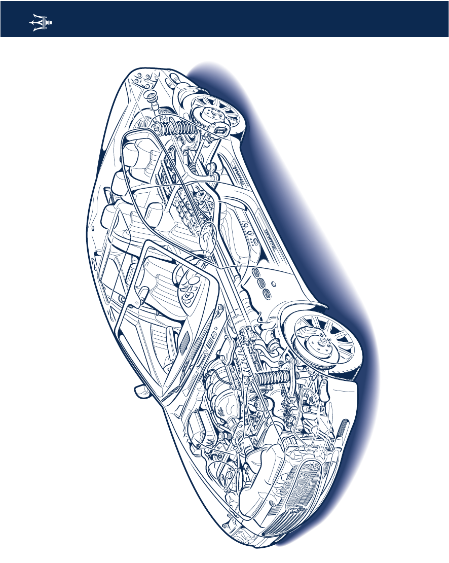
We thank you for choosing a MASERATI Quattroporte
This vehicle represents the result of MASERATI's great experience in the design and construction of sports cars for both
touring and racing.
The purpose of this manual is to provide you with an understanding of the equipment, systems and controls in the vehicle
and to explain how they work.
In the final section of this manual you will also find instructions for basic maintenance procedures and the complete Service
Time Schedule, which are needed to help ensure steady levels of performance, quality and driving safety. In addition, keep
in mind that proper maintenance is an essential factor contributing to the value of the vehicle over time and to protection
of the environment.
For Scheduled Maintenance or any other service, simply contact your local
Authorized Maserati Dealer
. Their technical staff
has the proper training and equipment to help ensure that all service work is carried out properly and reliably.
For your own safety and the safety of others, we recommend that you read this manual carefully before driving the vehicle.
The Owner's Manual is an integral part of the vehicle and therefore it must always be kept on board.
3

4
Historical info
Historical info
1914
The Alfieri Maserati garage is founded
in Bologna.
1926
Targa Florio, Tipo 26: debut and victory
of a vehicle sporting the Trident
symbol on the hood, inspired by the
statue of Neptune in Bologna.
1927
Emilio Maserati becomes the outright
Italian champion with the Type 26.
1929
Baconin Borzacchini in the Type V4:
World land speed record over 10 km at
246 kph.
1930
Borzacchini in the Type V4: first Grand
Prix victory in Tripoli.
1933
Maserati, the most prestigious
European manufacturer introduces the
hydraulic brake control in its racing
vehicles. Giuseppe Campari in a Type
8CM wins the French Grand Prix and
Tazio Nuvolari those in Belgium and
Nice.
1934
Giuseppe Furmanik in a Type 4CM:
World land speed record in the class
1100 at 222 kph.
1939
Wilbur Shaw on a 8CTF wins the
Indianapolis 500: Maserati is to remain
the first and only Italian manufacturer
to win on the legendary Indy motor
speedway.
1940
The company moves headquarters to
Modena.
1947
The first Granturismo is built: the A6
1500 with bodywork by Pininfarina.
The A6GCS racing version debuts
victoriously with Alberto Ascari on the
Modena circuit.
1954
The 250F, the single-seater which will
allow the Maserati to win the Formula
1 World Championships, makes its first
appearance winning in Argentina.
1957
Fangio in the 250F wins the world title.
At the end of the season, Maserati
officially withdraws from racing.
1961
The 3500 GT is the first Italian vehicle
to adopt fuel injection.
1963
Production begins of the Mistral and
the Quattroporte, the fastest sedan car
in the world.
1966
The Ghibli is presented, a coupé
designed by Giugiaro.
1968
The Citrôen becomes a partner in the
company and the V6 engine goes into
production.
The 2+2 Indy is presented.
1971
The Bora is presented, the first
Maserati Granturismo with a central
engine.
Followed a year later by the Merak.
1973
The Khamsin, designed by Bertone,
replaces the Ghibli.
1975
Citrôen leaves the company, which is
then bought out by Alejandro De
Tomaso.
1976
The new Quattroporte is presented,
designed by Giugiaro,
which will go on to be used as the
official car of the President of the
Italian Republic.
1981
De Tomaso changes marketing
strategy and starts production of the
Biturbo, a two-door sedan with a six-
cylinder engine.
5
Historical info
1989
The Shamal is the first vehicle to adopt
the new biturbo eight-cylinder engine.
1993
Fiat Auto buys out the entire Maserati
share package and in 1998 presents the
Quattroporte.
1997
Ferrari acquires the majority of
Maserati shareholding.
1998
Quattroporte Evoluzione V8 3.2 - V6
2.8.
3200 GT V8.
1999
3200 GT V8 Automatica.
2000
Alfieri Maserati Garage Customization
Program.
2001
Production begins of the Spyder with
4200 eight-cylinder engine and the
electro-hydraulic steering-wheel
mounted gearbox "Cambiocorsa".
Alfieri Maserati garages.
2002
The 2+2 Coupè is presented.
2003
A return to racing with the TROFEO.
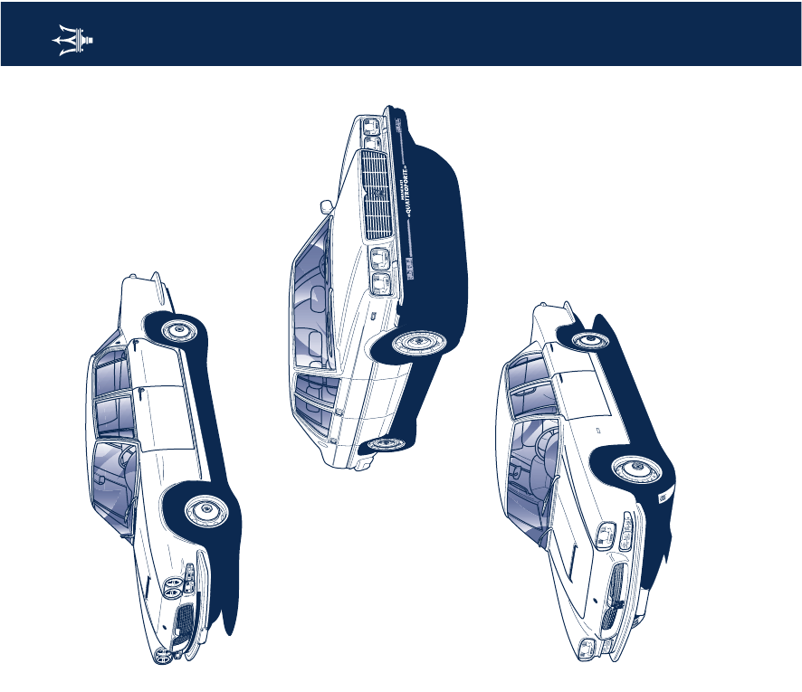
Quattroporte 1963
Quattroporte 1976
Quattroporte 1965
6
Introduction
Introduction
Consulting the Manual
To facilitate reading and rapid use, the
topics are sub-divided into SECTIONS
and CHAPTERS.
The important parts requiring
particular attention are easily
identifiable in the sections and
chapters:
EXTREME CAUTION
REQUIRED: failure to comply
with the instructions could
cause hazardous situations involving
personal and vehicle safety!
WARNING: aimed at preventing any
damage to the vehicle and thus
hazards involving the safety of
persons.
Abbreviations
Some descriptions and terms with
particular meanings are found in this
manual in an abbreviated form:
A.C.
- AIR CONDITIONING SYSTEM
ABS
- ANTI-LOCK BRAKING SYSTEM -
Wheel locking prevention
system during braking
ASR
- ANTI-SLIP REGULATION -
Prevention of skidding during
acceleration
EBD
- ELECTRONIC BRAKE-FORCE
DISTRIBUTION - Electronically
controlled distributor of
braking force
ECU
- ELECTRONIC CONTROL UNIT
MSP
- MASERATI STABILITY PROGRAM
Yaw prevention monitoring
system
Updating
The vehicle's high quality level is
enhanced by constant improvements.
Therefore, there may prove to be
differences between this manual and
your vehicle.
All specifications and illustrations
contained in this manual refer to those
resulting as of the printing date, and
are subject to change without notice.

7
Introduction
Service
The information contained in this
manual is limited to those instructions
and indications that are strictly
required for the use and good
preservation of the vehicle.
The Owner will certainly obtain
greater satisfaction and the best
results from the vehicle by following
these instructions carefully.
We also advise you to have all the
maintenance services and inspections
carried out at your local
Authorized
Maserati Dealer
, where you will find
specialized staff and suitable
equipment.
See the "SALES AND SERVICE
ORGANIZATION" manual for locations
of AUTHORISED MASERATI DEALERS
AND SERVICE CENTRES.
Your local
Authorized Maserati Dealer
is at your complete disposal for any
information and suggestions.
“DuoSelect”
The vehicle is equipped with a manual
gearbox system with double-plate dry
clutch, controlled by an electro-
hydraulic system by means of the levers
on the steering wheel.
Although the system can be used in
"automatic" mode, the "DuoSelect"
should not be considered as an
automatic transmission. Therefore, for
correct use, carefully follow the
instructions in the respective section of
this manual.
NHTSA’s Toll-free
Auto Safety Hotline
If you believe that your vehicle has a
defect which could cause a crash, injury
or death, you should immediately
inform the National Highway Traffic
Safety Administration (NHTSA) in
addition to notifying Maserati S.p.A.
or Maserati North America, Inc.
If NHTSA receives similar complaints, it
may open an investigation, and if it
finds that a safety defect exists in a
group of vehicles, it may order a recall
and remedy campaign. However,
NHTSA cannot become involved in
individual problems between you,
your dealer, or Maserati North
America, Inc.
To contact NHTSA, you may either call
the Auto Safety Hotline toll-free at 1-
800-424-9393 (or 1-703-366-0123 in
Washington, D.C. area) or write to:
NHTSA, U.S. Department of
Transportation, Washington, D.C.
20590. You can also obtain other
information about motor vehicle
safety by calling the Hotline.
Multi Media System
The vehicle is equipped with the
Maserati IT “Multi Media System”
which includes the following standard
features:
– on-board computer;
– satellite navigation system (where
digital maps are available);
– Bose Sound System;
– single CD-reader.
On request, the range of functions can
be further enhanced with the addition
of an optional GSM telephone (where
this standard is available), the CD-
changer, the TV module and the on-
board IT "CALL" services.
8
Introduction
“Run Flat” tires (optional)
The vehicle can be fitted with “Run
Flat” tires. This kind of tire is equipped
with reinforced sidewalls which
permit the vehicle to continue
traveling at moderate speed (50 mph -
80 km/h), even in the event of a
puncture, for a set distance.
When the control panel receives the
“punctured tire” information from the
tire pressure ECU, it monitors the
residual tire life by showing a warning
signal in the relevant area on the
display after 31 mi (50 km) and 62 mi
(100 km).
After 75 mi (120 km), the warning not
to continue will be displayed.
For further information on the display,
please refer to chapter: “Tire pressure
monitoring system” on Page 42.
WARNING: Always comply with the
specified wheel alignment values, as
this is fundamental to obtain the best
performance from and the longest life
of your tires.
Towing the vehicle
The vehicle has not been designed,
developed and homologated to be
used as towing vehicle of other means
(e.g. trailers, caravans, etc.) and
nothing may be loaded on the roof;
fitting structures such as bars or roof-
racks may damage the vehicle.
0 psi - 0 bar
Standard Run flat
0 psi - 0 bar
9
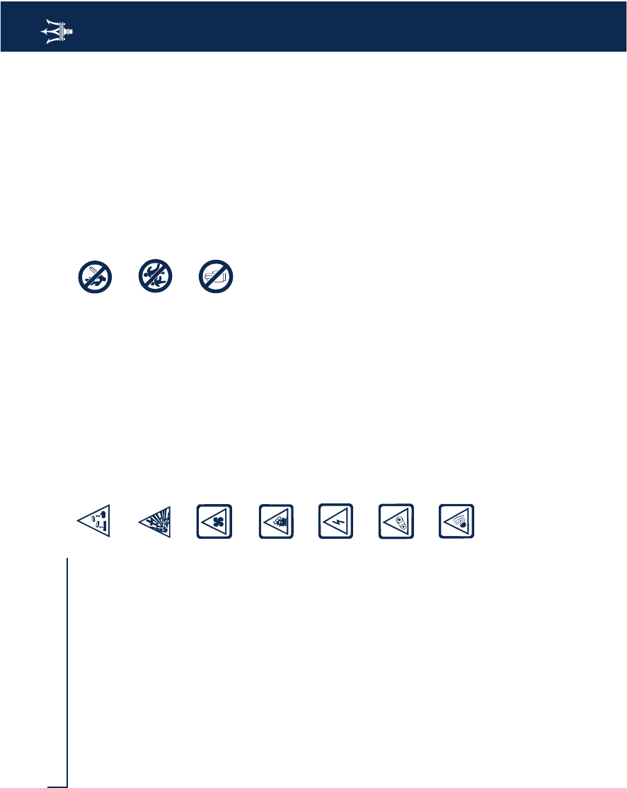
Symbols
Symbols
There are specific colored plates on or
near some of the components on your
MASERATI. The related symbols are
important warnings that the user must
follow when using the component
involved.
All of the symbols included in the
labelling on your MASERATI are listed
concisely here below, along with the
component involved with that symbol.
In addition, the meaning of the symbol
shown is also indicated in terms of the
following sub-division: danger,
prohibition, warning, compulsory -
with respect to that same symbol.
Danger symbols
Battery
Corrosive liquid.
Battery
Explosion
Fan
It can start up automatically
even with the engine stopped.
Expansion tank
Do not remove the cap when
the coolant is hot.
Coil
High voltage.
Belts and pulleys
Moving devices: keep body
parts and clothing away.
Air-conditioning lines
Do not open. Gas under high
pressure.
Symbols of prohibitions
Battery
Do not approach with naked
flames.
Battery
Keep children at a safe
distance.
Heat guards - belts - pulleys
- fans
Do not rest your hands on
these parts.
10
Symbols
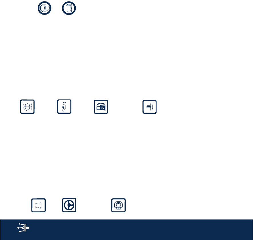
Warning symbols
Catalytic muffler
Do not park or stop over
flammable surfaces. Refer to
chapter: “Air Quality devices”.
Hydraulic steering
Do not exceed the maximum
level of fluid in the tank. Only
use fluid of the type
prescribed in then section
“Capacities and technical
specifications”.
Brake circuit
Do not exceed the maximum
level of fluid in the tank. Only
use fluid of the type
prescribed in the section
“Capacities and technical
specifications”.
Windshield
wipers
Only use fluid of the type
prescribed in the section
“Capacities and technical
specifications”.
Engine
Use only the lubricant
recommended in the section
“Capacities and Technical
specifications”.
Vehicle using lead-free
gasoline
Only “Premium gasoline” with
an AKI (Anti Knock Index)
rating no lower than 91
(approximately 96 R.O.N.)
must be used.
Expansion tank
Only use fluid of the type
prescribed in the section
“Capacities and technical
specifications”.
Symbols indicating compulsory
measures
Battery
Protect your eyes.
Battery - Jack
Refer to the Owner's Manual.

1
2
3
4
5
6
7
8
9
11
Symbols
Contents
Vehicle identification data
Active and passive safety
Instruments and controls
Before you drive
Using the vehicle
In an emergency
Capacities and technical specifications
Maintenance
Table of contents

12
Symbols

1
Symbols
13
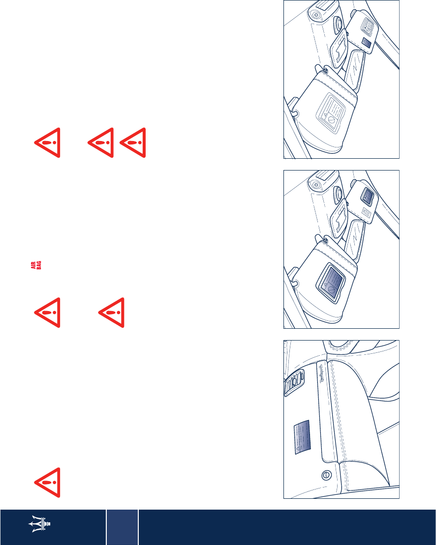
Vehicle identification data
Identification plates 14
Homologation plates 15
Instructions plates 17
Key codes 19
1
14
Identification plates
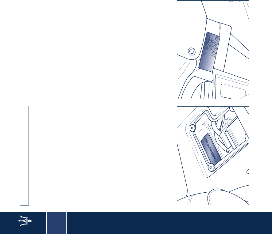
Identification plates
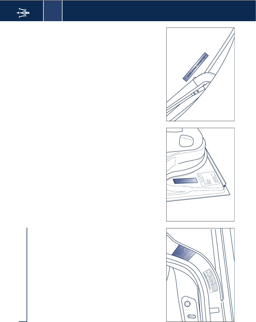
Chassis marking
The vehicle's registration number is
punched on the underfloor, in front of
the right-hand front seat.
To read the number, lift the mat and
remove the guard.
Engine marking
The identification number is punched
on the cylinder block and includes type
and serial number.
The engine type is also indicated on
the plate positioned on the front, left-
hand door's jamb.
1
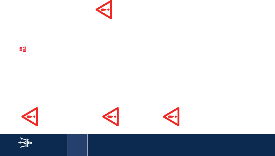
Homologation plates
15
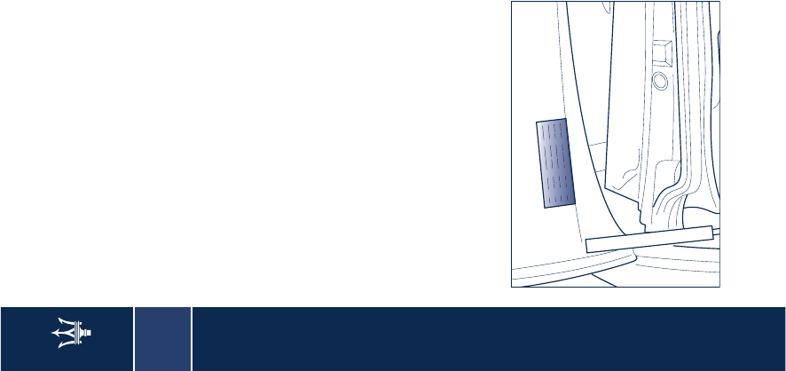
Homologation plates
– Plate for compliance with safety
standards;
– V.I.N. plate; – Chassis type and number;
1
16
Homologation plates
– Emission control data plate.
1
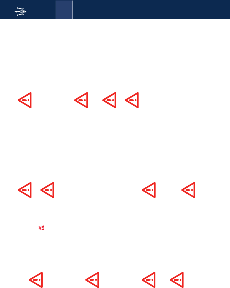
Instructions plates
17
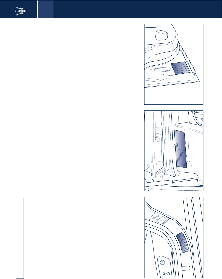
Instructions plates
– Tire specification plate;
– Lubricant plate; – Mercury content warning plate;
1
18
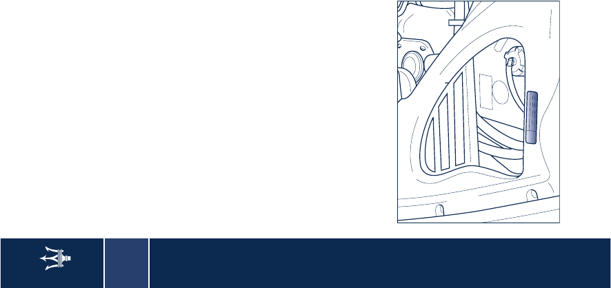
Instructions plates
– Anti-freeze plate.
1
Key codes
19
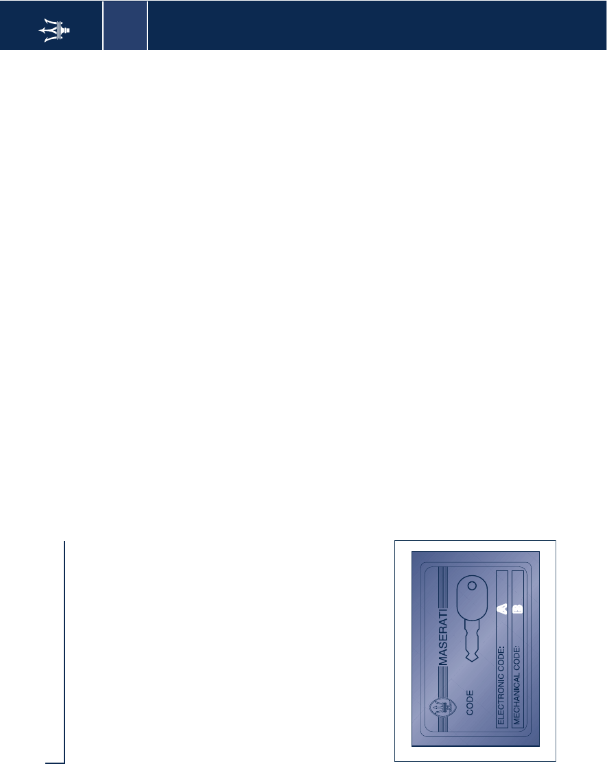
Key codes
A CODE CARD is supplied with the
keys. This card indicates the following:
– the electronic code
A
to be used in
the procedure for “emergency
starts”
– the mechanical key code
B
to be
given your local
Authorized
Maserati Dealer
when ordering
duplicate keys.
WARNING: The code numbers shown
on the CODE CARD should be kept in a
safe place.
WARNING: You are advised to always
keep the CODE CARD number with
you, as this is absolutely necessary in
the event of an “emergency start”.
WARNING: In the event of a vehicle
ownership transfer, it is essential that
the new owner is provided with all the
keys and with the CODE CARD.
WARNING: It is advisable to write
down and keep the codes listed on the
plates delivered with the keys and the
remote control in a safe place (not in
the car) in order to request duplicates
if needed.
A
B
7KLVGHYLFHFRPSOHVZLWK3DUWRIWKH)&&5XOHV
2SHUDWLRQLVVXEMHFWWRWKHIROORZLQJWZRFRQGLWLRQV
WKLVGHYLFHPD\QRWFDXVHKDUPIXOLQWHUIHUHQFH
WKLVGHYLFHPXVWDFFHSWDQ\LQWHUIHUQFHUHFHLYHG
LQFOXGLQJLQWHUIHUHQFHWKDWPD\FDXVHXQGHVLUHG
RSHUDWLRQ
)&&,'5;1%&/
,&$1%&/

20
Key codes

2
21
Active and passive safety
Seat belts 22
Safe transport of children 27
Front and side airbags 31
MSP System 38
ASR system (electronic anti-skid device) 39
ABS and EBD systems 40
Tire pressure monitoring system (optional) 42
Parking sensors (optional) 49
Fuel cut-out inertia switch 52
2
22
Seat belts
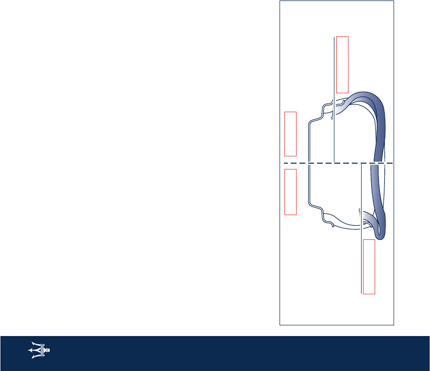
Seat belts
The vehicle is equipped with seat belts
with automatic retractor designed for
maximum freedom of movement.
The seat belts are provided with
electronically-operated pretensioners.
Moreover, the lower attachment
points are connected directly to the
seat to help provide maximum
protection.
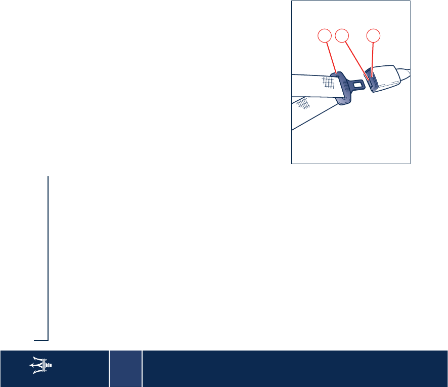
Fastening the seat belts
Extract the lower section of the seat
belt from the outer side of the seat and
secure it by holding the fastening tang
A,
and pulling out the belt until the
tang inserts into the buckle lock
B
.
The belt is correctly engaged when the
lock clicks into position. To release the
belts, press button
C
.
If the driver’s belt is not fastened,
when the ignition key is turned to
MAR
the warning light <
on the
instrument panel comes on and a
buzzer sounds for about 8 seconds.
The retractor locking device is
activated whenever the belt is pulled
out too rapidly or in case of sudden
braking or collision.
If the belt locks due to too rapid
extraction, allow it to retract a short
distance to disengage the locking
device.
The retractor allows the belt to
automatically fit to the passenger’s
body, allowing free movement.
When the vehicle is parked on a steep
slope, the retractor may lock: this is
normal.
WARNING: Feed the belt back into the
retractor by hand to avoid twisting and
snagging.
A
C
B
2
Seat belts
23
Adjusting the front seat belts
height (front seats only)
The seat belts height must be
adjusted with the vehicle
stationary.
Always adjust the height of the front
seat belts so that they suit the driver's
and passenger's height. This
precaution can reduce the risk of injury
in a collision substantially.
The correct adjustment is achieved
when the belt passes about mid-way
between the end of the shoulder and
the neck.
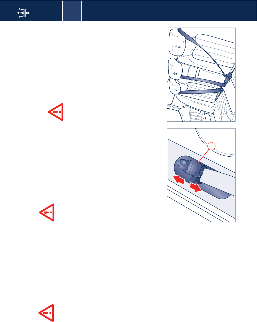
The upper attachment point of the
seat belts is equipped with an
oscillating ring capable of moving into
4 different positions, allowing the
belts position to be adjusted.
To move the attachment fitting, press
control
D
.
After the adjustment, always
check that the cursor to which
the oscillating ring is fixed, is
locked into one of the positions
provided. Therefore, with the
handgrip released, push again
downward to allow the anchoring
device to click into place, in the event
that it has not been released in one of
the positions provided.
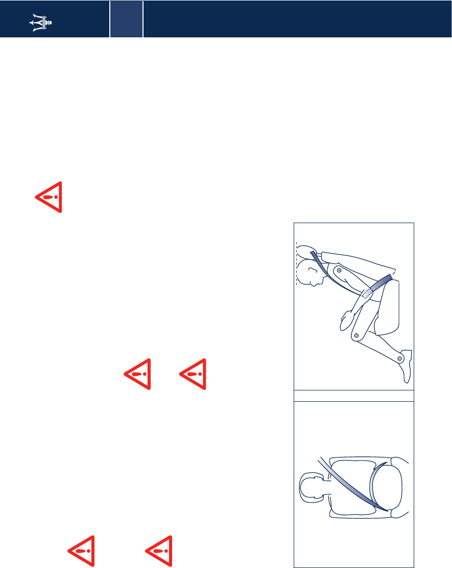
Using the rear seat belts
The belts for the rear seats must be
worn as shown in the figure.
Remember that, in the event
of a violent impact, the
passengers on the rear seats
that are not wearing the seat belts are
not only subject to personal injury but
they also represent a danger for
passengers sitting in the front seats.
The seat belts must be worn keeping
your chest in the upright position and
lying against the backrest.
When the rear seats are not occupied,
place the seat belt buckles in their
respective seatings.
D
2
24
Seat belts
Load limiting devices
To increase passive safety levels, the
front seat belt retractors are equipped
with a load limiting device designed to
control the belt reeling out, so that the
force exerted on the shoulders while
the seat belt is in restraining mode can
be suitably adjusted.
Pretensioners
To make the front seat belts still more
efficient, the vehicle is equipped with
pretensioners.
These devices are designed to
"detect", by means of a sensor, that
the vehicle is in a collision and retract
the belts by a few centimetres. This
helps ensure that the belt perfectly
adheres to the occupants’ bodies
before starting its restraining action.
The belt locking indicates that the
device has been activated; a small
amount of smoke may be visible.
The smoke is not toxic and is not
indicative of fire.
After the pretensioner activation, the
seat belt can be unfastened as usual,
by pressing the button on the buckle.
The pretensioner does not require any
maintenance or lubrication.
WARNING: Tampering with the device
will compromise its efficient operation.
If, as a result of exceptional natural
circumstances (floods, heavy seas, etc.),
the device has been in contact with
water and sludge, it is absolutely
essential to replace it.
To ensure the best protection from the
pretensioner, secure the belt snugly
across your chest and pelvis.
The pretensioners will
operate only once, and will
activate even if the belts are
not fastened. Therefore, they must be
replaced by your local Authorized
Maserati Dealer after operation. The
units have a ten year service life from
the date of manufacture; they must
be replaced when their service life is
near to expiry.
WARNING: Work on the vehicle which
involves blows, vibrations or localized
heating (over 100°C for 6 hours max.)
in the area of the pretensioners may
damage or activate them: vibrations
due to uneven road surfaces or
mounting the pavement
unintentionally, for instance, should
not affect the units. Contact your local
Authorized Maserati Dealer
for any
intervention that may be required.
It is strictly forbidden to
remove or tamper with the
pretensioner components.
Any intervention must be carried out
only by qualified and authorized
personnel. Always contact your local
Authorized Maserati Dealer.
2
Seat belts
25
General warnings for using the
seat belts
The driver is obliged by law to
respect and obey, also in
relation with the passengers
carried, the provisions of local
legislation regarding the compulsory
use of seat belts.
To help provide maximum
protection, you are advised to
keep the seatback in the most
upright position possible and the seat
belt close to your chest and pelvis. If
the seat belt is loose, in the event of
an accident you could move too far
forward and could be injured.
Travelling with the seatback too far
reclined could also be dangerous: even
if the seat belts are fastened, they may
not work correctly. In fact, the belt
itself may not be close enough to your
body and, if it is in front of you, it
could cause neck wounds or other
injuries in an accident. Additionally, in
an accident, the lower section of the
belt could press against the upper part
of your stomach rather than the pelvic
area, causing serious internal injuries.
When travelling with one or
more child seats fitted on the
rear seat of the vehicle, the
tables must be in closed position.
When the vehicle is moving
and the table/s is/are open,
passengers traveling in the
rear seats must fasten their seat belts.
Travelling without the seat belt
fastened increases the risk of injury in
the event of a collision.
Always fasten the seat belts.
Travelling without the seat
belts fastened increases the
risk of serious injury in the event of a
collision, even with the airbags. In the
event of a collision, the seat belts
reduce the possibility of the vehicle's
occupants being thrown against the
structures of the passenger
compartment or out of the vehicle.
The airbags are designed to work
together with the seat belts, not to
substitute them. The front airbags
only intervene in the event of certain
head-on collisions of medium or high
intensity. They will not be activated if
the vehicle rolls over, or in the event of
rear bumps or minor frontal collisions.
2
26
Seat belts
Do not fasten your seat belt
using the buckle lock for the
other seat: in the event of an
accident, the lower section of the belt
could press against the upper part of
your stomach rather than the pelvic
area, causing serious internal injuries.
It is extremely dangerous to
travel with the belt positioned
underneath your arm. In the
event of an accident, you would be
thrown forward and would likely
suffer head and neck injuries.
Additionally, if the belt presses against
your ribs, it could cause serious
internal injuries.
The belt must not be twisted;
make sure that it is snugly
fitted to the driver's and
passenger's bodies. In fact, in an
accident, the restraining force would
not be distributed evenly along the
belt and would consequently cause
injuries. The upper part of the belt
must pass over the shoulder and
diagonally across the chest. The lower
section must adhere to your pelvis, not
the stomach, to avoid that you slide
forward in the event of a collision. Do
not use devices (clips, fastenings etc.)
that prevent the seat belts from laying
close to the passengers' bodies.
Do not carry children on a
passenger’s lap using only one
seat belt for protecting both
of them.
If the seat belt has been
suffered a heavy mechanical
stress, for example during a
collision, it must be completely
replaced together with its anchorages,
the screws fastening the said
anchorages and the pretensioner. In
fact, even if there are no visible
defects, the resistance level offered by
the seat belt could be reduced.
Pregnant women must
scrupulously observe local
legislation regarding the use
of seat belts. Make sure, in any case,
that the lower section of the belt is
positioned well down on the hips,
below the abdominal region of the
body.
How to keep seat belts efficient
1)
Always use the seat belts keeping
the belt perfectly flat, not twisted;
make sure the belt can slide freely,
without jamming.
2)
The seat belts must be replaced
following every pretensioner
activation and whenever the belt itself
shows visible damages or abrasions.
3)
Wash the seat belts by hand using
water and neutral soap, rinse them
and let them dry in the shade. Do not
use strong detergents, bleaches or
colourants and any other chemical
substance that could weaken the belt
fibers.
4)
Make sure the retractors do not get
wet: as they will not operate properly.
2
Safe transport of children
27
Safe transport of children
For the best protection in the event of
a collision, all the vehicle's occupants
must travel seated and protected by all
the suitable restraining systems. The
seat belts are designed to be used by
persons whose physical characteristics
(age, height, weight) are provided for
by established legislation in each
country. Anyone who does not comply
with these provisions may not travel in
the front passenger seat. This also
applies to children. Their heads are
proportionally heavier and larger than
those of adults, while their bones and
muscles are relatively undeveloped. To
help protect them in case of a collision,
they must use special restraint or safety
systems.
We recommend that you
always carry children in the
specific restraining systems
installed on the rear side seats, as this
is the best place in the event of a
collision.
No child under 12 should
travel in the passenger seat.
No child seat can be installed
in the rear, central seat.
When travelling with one or
more child seats fitted on the
rear seat of the vehicle, the
tables must be in closed position.
Children must never travel
seated on a passenger's lap. A
child weighs very little until a
collision occurs! In a collision, a child
becomes so heavy that it is impossible
to hold onto him or her. For example,
in the event of a collision at only 25
mph (40 km/h), a child weighing 12 lb
(5.5 kg) exerts a force equal to 240 lb
(110 kg) on the arms of the person
carrying him/her. Children must
always be protected by a suitable
restraining system when travelling.
Children who are resting on
the airbag or are too close to it
when it is activated, may be
seriously injured. The airbags and
pretensioners are designed to offer
suitable protection for adults and
teenagers, but not for children and
babies. Neither the seat belts or the
airbags are designed for them.
Children and babies must travel in
suitable restraining systems.
Babies must be supported
completely, including their
head and neck. This is
necessary since the babies' neck is
weak while their head is
proportionally bigger and heavier in
relation to their body. In a collision, if
a baby is travelling in a rearward-
facing seat, the forces of an impact are
distributed throughout the strongest
parts of the body, i.e. the back and
shoulders. Babies must always be
protected by a suitable restraining
system when travelling.
Babies travelling in a
rearward-facing seat or
children travelling in a child
seat may be seriously injured in the
event of airbag activation. This could
happen because the seatback of the
child's seat may be positioned
extremely close to the airbag at the
moment it is inflated. Do not place an
infant or a child in the front passenger
seat at any time.
2
28
Safe transport of children
The structure of a child's body
is completely different from
that of an adult or a teenager
(whom the seat belts are designed
for). Children's hips are so small that
the seat belt will not stay in the correct
position on them. The belt may rise up
on the child's stomach and, in the
event of a collision, can cause serious
internal injuries. Children must always
be protected by suitable restraining
systems.
All minors whose physical
characteristics (age, height, weight)
fall within the value ranges/limits
provided by the established legislation
in each country must be protected by
special restraint or safety systems
(certified child seats, booster seats).
Make sure to always use approved
universal child restraining systems.
Follow the instructions that the
manufacturer of the devices is
compulsorily required to supply
together with the child restraint
systems.
To ensure the best restraining action of
the child seats, we recommend that
you choose the model that best suits
the shape of your seats. If possible, try
to install the seat on the vehicle before
purchasing it.
To guarantee the best
restraining action of the child
seat, we recommend that you
choose the seat that best suits the
shape of your vehicle's seat and that
you try to install the child seat before
purchasing it.
In the event of an accident, an
improperly fastened child
restraining system can
increase the risk of injury.
Rearward-mounting child
seats must not be used on
front passenger seats
equipped with active airbags, as these
could cause serious injuries during
inflation, even in minor collisions.
No modifications can be made
to the seat belts and the child
restraining systems.
Established legislation in some
countries already provides that
children under 12 years of age may not
travel in the front passenger seat.
Below is a summary of the safety
regulations applying to the transport
of children:
We recommend that you always carry
children in the specific restraining
systems installed in the rear outbound
seats, as this is the safest place in the
event of a collision.
Always and strictly follow the
instructions that the manufacturer
provides with the seat.
Keep the instructions in the vehicle
together with the documents and this
handbook. Do not use a seat which
does not have any instructions for use.
WARNING: We recommend that you
choose the seat that best suits the
shape of your vehicle's seat and that
you try to install the seat before
purchasing it.
Always pull on the seat belt to check
that it is locked in.
All restraint system must be used by a
single passenger only: never carry two
children in the same seat.
Always check that the seat belts are
not resting against the child's neck.
Do not allow the child to assume
incorrect positions or undo the seat
belt /child seat safety harness during
travel.
2
Safe transport of children
29
Do not carry children in your arms,
even new born children. Nobody,
however strong, can hold on to a child
in the event of a collision.
After an accident, always replace the
child seat with a new one.
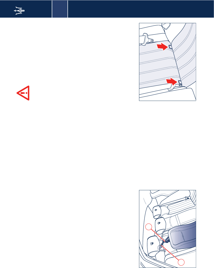
The vehicle outfitting is designed for
mounting child seats with top
anchoring.
To fit the child seat, run the belt
A
through the support pins of the
headrest and anchor it on one side to
the backrest of the child seat and on
the other side to the bracket
B
on the
car body.
Isofix seats
The rear side seats of the vehicle are
equipped with anchoring points for
Isofix child seats. This is a new system
complying with European standards
for carrying children.
This system offers a special anchoring
system for child seats, which uses two
metal brackets positioned between
the seat cushion and backrest.
The seats designed for Isofix child seats
installation can however be fitted with
standard child seats;
as a matter of fact, you can install a
standard and an Isofix child seat at the
same time.
No more than two standard child seats
and two Isofix type child seats can be
installed on the rear seats.
Only standard type child seats can be
mounted on the front passenger seat.
Fit the child seat only when
the vehicle is stationary. The
child seat is correctly anchored
to the provided brackets when a click
indicates it is locked in place. Follow
the mounting, removal and
positioning instructions provided by
the child seat Manufacturer.
A
B
2
30 Safe transport of children
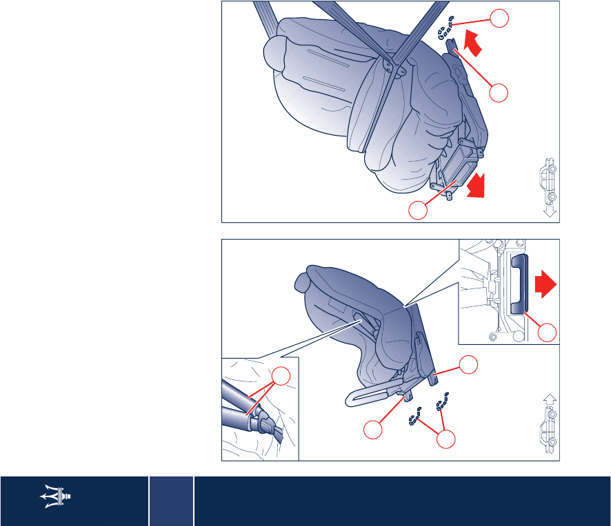
Fitting the child seat in
rearward-facing position
To fit the child seat in a rearward-
facing position, be particularly careful
that the brackets C are properly
inserted in their seatings E.
The baby is then secured by the child
seat's harness F.
Fitting the child seat in
frontward-facing position
For installation, proceed as follows:
– make sure that the release lever D is
in the standby position (retracted);
– align the anchoring points C with
the brackets E, then push the seat
until you hear it click into place,
which indicates it is secured
– check for correct locking by trying to
move the child seat with strength;
the safety mechanisms in fact, help
prevent the child seat from being
improperly fitted if only one of the
attachment fittings is locked.
With this type of configuration, the
child is also restrained by the vehicle
seat belts and by the upper belt.
In any case, see the instruction booklet
provided with the child seat for fitting
the vehicle belts into the seat correctly.
C
D
E
F
E
C
E
D
2
Front and side airbags 31
Front and side airbags
18 17
2
5
3
7
8
1
14
13 12 9
11
10
15
9
4
6
16 5

2
32 Front and side airbags
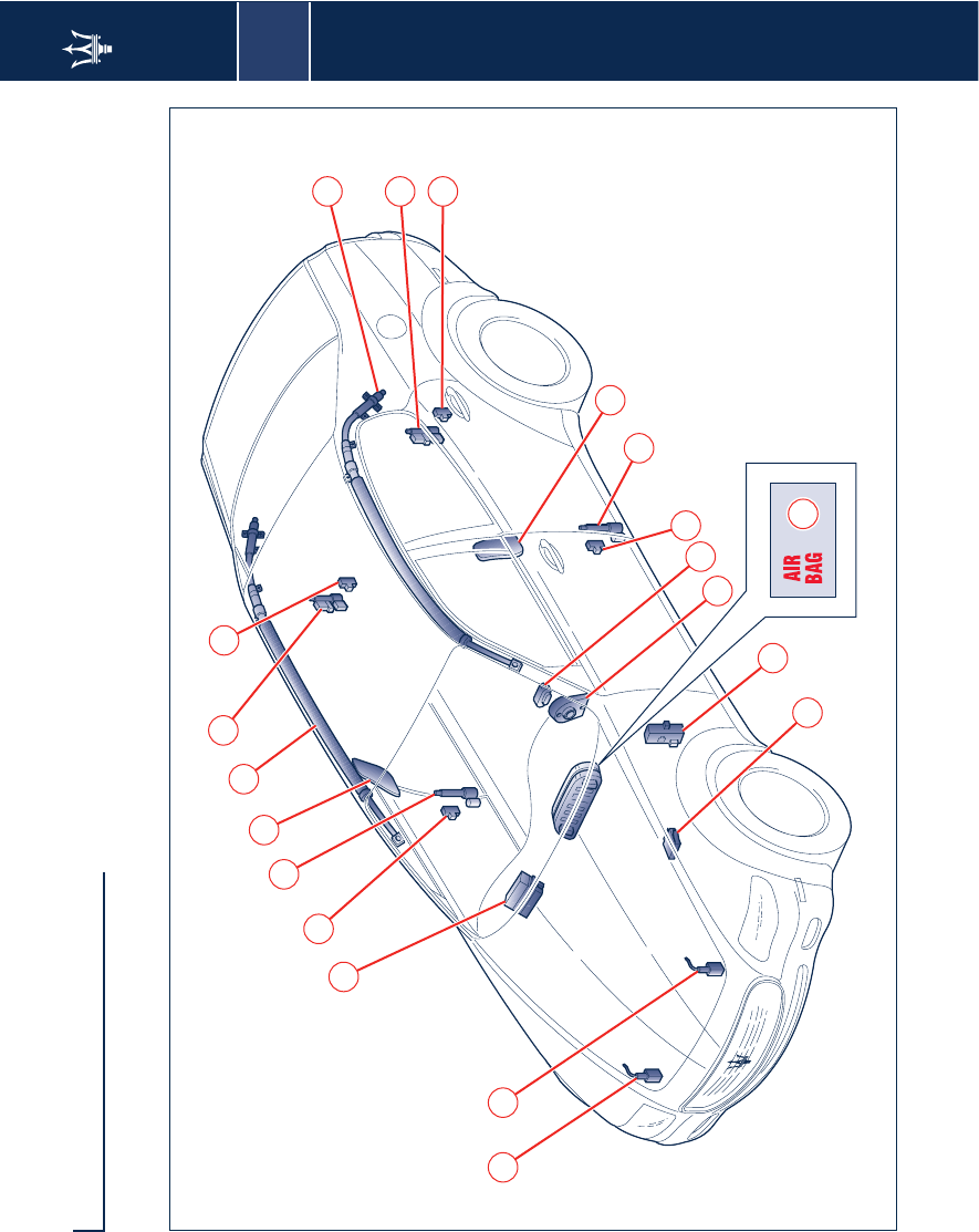
The vehicle is equipped with 6 airbags
(2 front and 4 lateral ones) and
electronically-operated pretensioners
for all of the seat belts.
The system components are the
following:
1) Electronic control unit
2) Passenger's front airbag
3) Front passenger seat belt
pretensioner
4) Passenger side bag
5) Satellite collision sensor on
passenger side
6) Passenger’s window bag
7) Driver’s window bag
8) Driver side bag
9) Satellite collision sensor on driver
side
10) Front, driver seat belt's
pretensioner
11) Airbag system failure warning light
12) Driver's lateral airbag
13) Clock Spring
14) Diagnostics socket
15) Rear left-hand pretensioner
16) Rear right-hand pretensioner
17) Front left-hand Crash Zone Sensor
18) Front right-hand Crash Zone
Sensor.
Front airbags
The front airbags (for the driver and
passenger) are safety devices which are
designed to intervene in the event of
certain head-on collision of sufficient
impact.
They consist of an instantaneously
inflating bag housed in a special
compartment:
– in the center of the steering wheel
on the driver side;
– in the dashboard and with a larger
size bag (full size airbag) on the
passenger side.
The front airbags (for the driver and
passenger) are safety devices designed
to protect the occupants in the event
of a medium or high intensity head-on
collision, which act by placing a
cushion (bag) between the occupant
and the steering wheel or the
instrument panel dashboard.
In the event of a collision, an ECU
processes the signals coming from a
deceleration sensor and triggers,
whenever necessary, the inflation of
the bag.
The bag inflates instantaneously
between the front passengers and
potentially harmful structures. The
bags deflate immediately afterwards.
2
Front and side airbags 33
In the event of a collision,
anyone not wearing a seat
belt will be thrown forward
and will come into contact with the
bag before it is fully inflated. This
reduces the protection offered by the
bag. It follows that the front airbags
(driver and passenger side) do not
replace or substitute the seat belts but
supplement them, and hence the seat
belts must always be worn as
provided by established legislation in
most other parts of the world.
Remember that, in the event
of a violent impact, the
passengers on the rear seats
that are not wearing the seat belts are
not only subject to personal injuries
but they also represent a danger for
passengers sitting in the front seats.
Never remove the steering
wheel! If necessary, this
operation should only be
performed by your local Authorized
Maserati Dealer.
In the case of low intensity head on
collisions (in which the retaining action
of the seat belts provides adequate
protection), the airbags do not inflate.
The airbag does not activate in the
event of rear or side collisions, and it
does not provide supplementary
protection.
Therefore non-activation of the
airbags in these cases is not an
indication of a system malfunction.
Passenger's airbag
(full size airbag)
The passenger airbag is designed to
afford supplementary protection to a
person wearing the seat belt.
When fully inflated, it will fill most of
the space between the passenger and
the dashboard.
SERIOUS DANGER: the
vehicle is fitted with an
airbag on the
passenger side. Do not allow infants
or children to travel in the front
passenger seat. Do not install an
infant or child safety seat in the front
passenger seat. If the passenger side
airbag is deployed, serious injuries or
death could result.
2
34 Front and side airbags
The vehicle is not provided
with a manual deactivation
switch for the passenger side
airbag; it is prohibited to carry children
on a rearward facing child-seat
mounted on the passenger seat. This
regulation is also indicated on the
plates attached on the visors and
inside the glove compartment.
If the warning light comes
on while driving (fault signal)
stop the vehicle and contact
the local Maserati Dealer to have the
system checked.
Rearward-mounting child
seats must not be used on
front passenger seats
equipped with active airbags, as these
could cause serious injury during
inflation, even in minor collision.
We recommend that you
always carry children in the
specific restraining systems
installed on the rear out bound seats.
No child seat can be installed
in the rear, central seat.
The plate on the right-hand
sun visor, near the courtesy
mirror, shows the instructions
for the replacement of the airbag
system. Contact the local Authorized
Maserati Dealer to replace the system
when the related expiry date
approaches.

2
Front and side airbags 35
Front and rear lateral airbags
The lateral airbags are designed to
enhance the protection offered to
passengers travelling in the front seats
in case of moderate to severe lateral
collision.
They consist of two types of
instantaneous inflation bags:
– Side Bags housed in the front seats'
backrests; this solution allows the
airbag to be always on approximate
position with respect to the
occupant, regardless of the seat
position.
– Window bags housed behind the
roof lateral panels and covered by
special trim panels that do not
interfere with the bags' unfolding
downwards during inflation. This
solution, designed to help protect
the head region, offers passengers
sitting in the front and in the rear
appropiate protection in the case of
a side impact, thanks to the large
area covered by the bags.
In the event of a side impact, an
electronic control unit processes the
signals coming from a deceleration
sensor and deploys the side airbags if
necessary.
The bags inflate instantaneously,
acting as a protection between the
occupants' body and the side of the
vehicle. The bags deflate immediately
afterwards.
WARNING: The electronic control unit
provides for the activation of the
pretensioners, front airbags or side
airbags (front and rear) based on
different criteria, according to the type
of impact.
The fact that one or more systems do
not activate is not indicative of a
system malfunction.
In the case of low impact lateral
collisions (for which the retaining
action of the seat belts affords
adequate protection), the airbags are
not designed to inflate.
It follows that the front airbags (on
driver and passenger side) do not
replace or substitute the seat belts but
supplement them, and hence the seat
belts must always be worn as provided
by established legislation in most
countries.
WARNING: The front and/or lateral
airbags may inflate if the vehicle
suffers a violent impact beneath the
car body, for example when mounting
the pavement, colliding with steps or
speed bumps, potholes etc.
WARNING: Airbag inflation releases a
small amount of powder. This powder
is not harmful and does not indicate
the presence of fire; furthermore the
surface of the deployed bag and the
interior of the vehicle may be covered
with a powdery residue: this powder
may irritate skin and eyes. If contact
occurs, wash with a pH neutral soap
and water.
2
36 Front and side airbags
If the warning light
switches on when the vehicle
is running (indicating a fault),
contact your local Authorized
Maserati Dealer as soon as possible to
have the system checked.
WARNING: The airbag system has a
service life of 10 years. Contact your
local Authorized Maserati Dealer
when this period is near to expiration
In the event of a collision with
consequent airbag inflation,
contact your local Authorized
Maserati Dealer for replacement of the
entire safety system, electronic control
unit, seat belts, pretensioners, and to
have the vehicle’s electrical system
checked.
All testing, repairs and
replacements of the airbag
system must be done by a
Maserati Service Network Center.
WARNING: In case of scrapping of the
vehicle, contact your local Authorized
Maserati Dealer to have the system
deactivated.
WARNING: If the vehicle is sold, the
new owner must be informed of the
aforesaid instructions for use warnings
and he/she must also be provided with
the "Owner's Manual".
The electronic control unit
activates the pretensioners
and front/lateral airbags
based on different criteria, according
to the type of collision. The fact that
one or more systems do not to activate
is not indicative of a system
malfunction.
2
Front and side airbags 37
General warnings
When the ignition key is
turned to the MAR position,
the warning light comes
on, but it must switch off after approx.
5 seconds. If the warning light fails to
come on at this time, or stays on, or
lights up when driving, contact your
local Authorized Maserati Dealer
immediately.
Drive with both hands on the
steering wheel rim, so that if
the airbag inflates it can do so
freely, without encountering obstacles
which can cause serious injuries. Do
not drive with your body curved
forwards but keep the seatback
upright, with your back fully against
it.
Do not apply stickers or other
objects to the steering wheel
or the passenger’s airbag
compartment.
Do not travel with objects in
your lap, in front of your chest
or especially with a pipe,
pencil or other objects held in your
mouth. In the event of a collision, the
intervention of the airbag could result
in serious injury.
Do not cover the front
seatbacks with clothing or
covers.
Note that with the ignition
key inserted and turned to the
MAR position, even with the
engine switched off, the airbags can
inflate even if the vehicle is stationary,
if it is run into by another vehicle.
Therefore, even with the vehicle
stationary, children must be secured
by the specific child restraint systems
installed on the passenger seat. On the
other hand, the airbags will not inflate
in case of collision with the vehicle
stationary and the key removed from
the ignition block; failure of the
airbags to inflate in these
circumstances is not indicative of a
system malfunction.
If the vehicle has been the
object of theft or attempted
theft, if it has been vandalized
or involved in flooding, contact your
local Authorized Maserati Dealer to
have the airbag system checked.
If interventions are carried out
on the electrical system
incorrectly, the airbag could
be activated, thereby causing injuries
to anyone in the vicinity.
The airbags do not substitute
the seat belts but afford
supplementary protection.
Moreover, in the event of head-on
collisions at low speed, side impacts,
rear bumps or roll-overs, the
passengers are protected by the seat
belts only, that must always be
fastened.
Do not wash the seats with
water or pressurised steam
(by hand or in the automatic
seat wash stations).
Do not hang rigid objects onto
the clothing hooks or onto the
handholds.
The airbags do not substitute
the seat belts but afford
supplementary protection.
Moreover, since the front airbags do
not intervene in the event of head-on
collisions at low speeds, side impacts,
rear bumps or roll-overs, in these cases
passengers are protected by the seat
belts only, that must always be
fastened.
2
38 MSP System
MSP System
The vehicle is equipped with the MSP
(Maserati Stability Program) yaw
prevention monitoring system,
encompassing all of the vehicle's
control systems: ABS, EBD, ASR and
MSR. The system is fitted with a unit
that is designed to predict the vehicle's
behavior accurately. The system is
capable of detecting whether the
driver is about to lose control of the
vehicle. In this case, it can activate the
brake calipers individually and the
engine control, in order to create a
torque sufficient to resist the vehicle's
yawing movement.
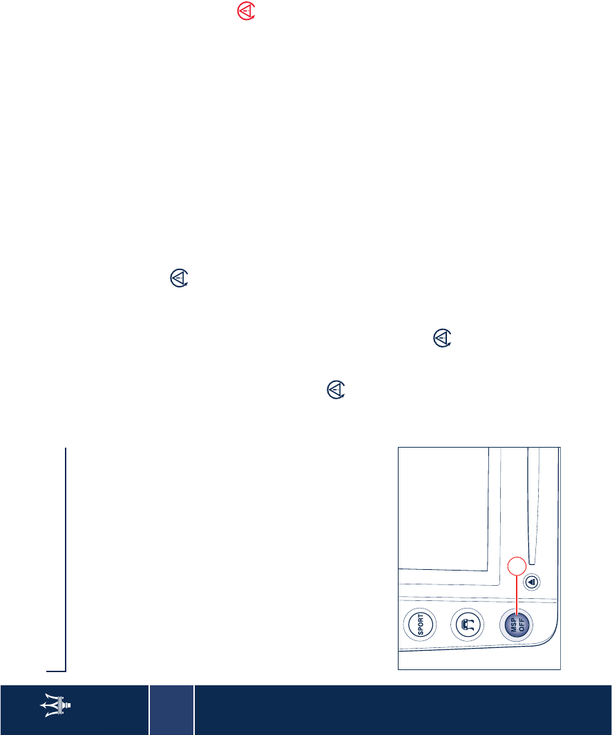
Activation
The MSP system is activated
automatically every time the engine is
started, and it can be disengaged by
pressing button A for approx. 2
seconds. Press button A again to
reactivate the system.
During all the system operating stages,
the green warning light
accompanied by the message “MSP
system active” will be lit up on the
display.
Fault indicators
In the event of a fault, the system is
automatically disabled and cannot be
reactivated. This condition is signalled,
while driving, by the amber warning
light that comes on both on the
instrument panel and on the multi-
function display. On the latter, the
warning light is accompanied by the
message “MSP system failure”.
When the engine is started, the system
malfunction is indicated by the
warning light switching on.
WARNING: In the event of a fault with
the MSP disabled, the vehicle will react
as if it were not equipped with this
system: have the system checked by
your local Authorized Maserati Dealer
as soon as possible.
WARNING: Make sure that the ignition
key is turned to STOP if you have to
tow the car with 2 wheels raised off
the ground. Otherwise, with the MSP
switched on, the respective control
unit will store a malfunction, resulting
in the warning lights coming on
the instrument panel and on the
display: this requires the intervention
of your local Authorized Maserati
Dealer to restore the system.
WARNING: In low grip conditions (ice,
snow, sand, etc.) it is advisable not to
use the SPORT mode function, even
with the MSP system active.
WARNING: Driving on parabolic curves
will deactivate the system.
A
2
ASR system (electronic anti-skid device) 39
ASR system (electronic
anti-skid device)
The ASR system is designed to help
prevent skidding of the driving wheels
during acceleration by means of the
engine control unit (spark advance
delay, engine throttle opening
reduction and fuel injection cut-out)
and of the rear brakes.
The ASR system enhances the vehicle
stability and improves active safety
while driving, especially under the
following conditions:
– internal wheel skidding on curves
because of the dynamic load
variations or excessive acceleration
– excessive power transmitted to the
wheels, also in relation to the road
conditions
– acceleration on slippery, snowy or icy
roadbeds
– loss of road grip on wet roads
(aquaplaning).
The ASR system works jointly with the
electronic suspension adjusting
system: under normal conditions
(SPORT mode off), stability in low and
medium grip conditions has priority,
while with the SPORT mode active,
the system favors traction, thereby
optimising vehicle's performance.
Activation
The ASR system is automatically
activated every time the engine is
started and can be cut-out by pressing
button A for about 2 seconds.
Press button A again to reactivate the
system.
During all the system operating stages,
the green warning light,
accompanied by the message “ASR
system intervention” will be lit up on
the display.
Fault indicators
In the event of a fault, the system is
automatically disabled and cannot be
reactivated. This condition is signalled,
while driving, by the amber warning
light, that comes on both on the
instrument panel and on the multi-
function display, accompanied by the
message "ASR system failure.
MSR function (engine braking
torque adjustment)
The ASR system is also desined to
controls the engine braking torque
when the accelerator pedal is released
under low grip conditions (snow, ice,
etc.): in these conditions, in fact, the
engine's high braking torque may
cause instability of the vehicle.
The system, using the same sensors as
the ABS, detects the skidding arising
on one or both of the driving wheels
when the accelerator is released and
opens the motor driven throttle for the
engine supply system, thereby
reducing the braking torque and
restoring the driving wheels'
maximum grip conditions.
WARNING: The maximum deceleration
that can be obtained with the engine
braking always depends on the tire
grip on the roadbed. Snow or ice
obviously reduce grip levels.
2
40 ABS and EBD systems
ABS and EBD systems
The vehicle is equipped with ABS (Anti-
lock Brake System) and EBD (Electronic
Brakeforce Distribution) systems
which, by means of the ABS system
sensors and the ECU, are designed to
improve the braking system’s
performance.
In the event of an emergency stop or
braking on slippery surfaces (e.g.
snowy or icy roadbeds), the ABS,
together with the standard braking
system, allows the driver to apply
maximum braking force without
causing the wheels to lock and
consequently losing control of the
vehicle.
The system is based on an electronic
control unit that processes the signals
coming from sensors fitted on the 4
wheels.
When a wheel tends to lock, the sensor
warns the unit which, in turn, request
to an electro-hydraulic unit to
intervene by modulating the pressure
exerted on the brake; the driver will
perceive a “pulsation” on the brake
pedal which is completely normal.
In the event of a failure, the system will
be deactivated, but this will not affect
the efficiency of the standard braking
system.
The failure will be indicated through
the lighting up of the red warning
light with the letters ABS > on the
instrument panel.
In this case, we recommend you
contact the nearest your local
Authorized Maserati Dealer centre,
which, thanks to the self-diagnostics
system the vehicle is equipped with,
should be able to quickly identify the
problem immediately.
The vehicles must be fitted
with wheel rims, tires and
brake pads of the type and
make approved by the Manufacturer
for the model concerned.
Despite the fact that this
device makes a considerable
contribution to safety, it is still
essential to drive particularly carefully,
especially when the road surface is
wet, covered with snow or ice.
The vehicle is equipped with
Electronic Brakeforce
Distributor (EBD). The
warning lights > “BRAKE” comes
when the engine is running to indicate
a fault in the EBD system; in this case,
sharp braking could lead to early
locking of the rear wheels, and
consequent possible skidding of the
vehicle. Drive with the utmost care
and immediately go to the nearest
your local Authorized Maserati Dealer
to have the system checked.
2
ABS and EBD systems 41
The warning light > usually
comes on when the engine is
running to indicate a fault in
the ABS system only. In this case, the
braking system is designed to will be
still efficient, but it will not make use
of the anti-locking device. Under these
conditions, the EBD system efficiency
can also be reduced. Drive with the
utmost care to avoid abrupt braking
and consult the nearest your local
Authorized Maserati Dealer
immediately.
If the low brake fluid warning
light BRAKE comes on, stop
the vehicle and check the
brake fluid level immediately. If the
fluid level is below the minimum
notch, top up with the recommended
fluid and contact your local
Authorized Maserati Dealer
immediately to have the system
checked. Brake fluid leaks impair the
operation of the entire.
System performance in terms
of active safety is not a reason
for the driver to take
unnecessary risks. The driving style
must always be suited to weather
conditions, range of visibility and road
traffic conditions.
The maximum obtainable
deceleration is always
dependent on the grip
between tire and road. With snowy or
icy roadbeds, grip levels are obviously
reduced and the braking distance is
very high, even with the ABS system.
2
42 Tire pressure monitoring system (optional)
Tire pressure monitoring
system (optional)
The vehicle is equipped with a system
that monitors the tire pressure by
means of special sensors that are
secured inside the wheel rims, in
position with the inflation valve. These
sensors transmit a signal that is
detected by the aerials fastened on the
car body, behind the fenders, and
connected to the ECU.
WARNING: The system can
momentarily experience radio-electric
interference emitted by devices using
similar frequencies.
The ECU processes this information
and, via the CAN line, transmits a series
of tire pressure data and system errors,
if any, to the on-board instrument
panel.
The signal transmitted by the ECU
activates some icons on the display.
The system is equipped with a specific
wiring that connects the aerials, the
control unit and the calibration button
to the vehicle's electrical system.
The system warns the driver
that there is a drop in tire
pressure. This warning does
not exempt the driver from
periodically checking the tires and
from complying with the prescribed
tire pressure levels.
WARNING: The system stores the tire
pressures as a reference rate, therefore
tires must be inflated to the prescribed
pressure.
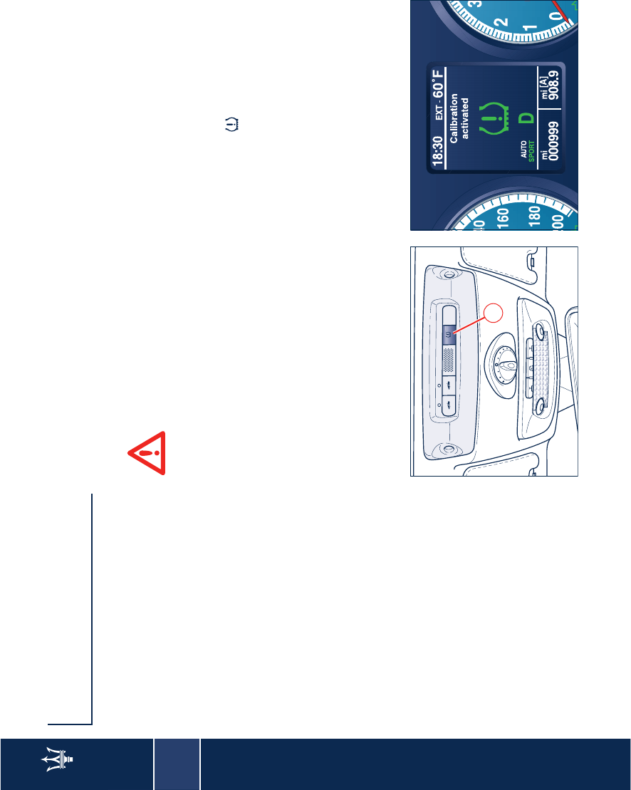
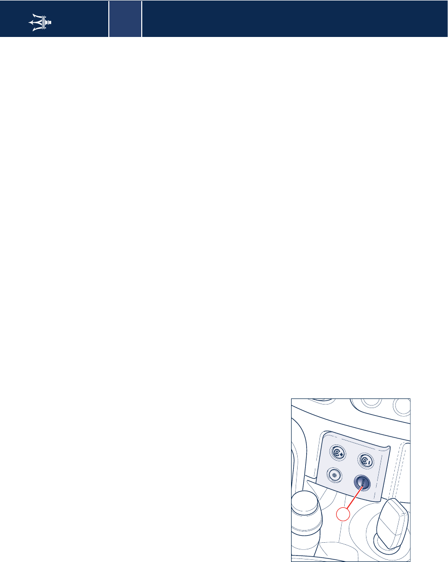
System calibration
After replacing or inflating one or
more tires, the system must be
calibrated once again.
To calibrate the system keep button A,
located on the inside roof, pressed
down for a time ranging between 4
and 10 seconds. The system takes a
maximum of 20 minutes to complete
the calibration procedure with the
vehicle in motion.
A green symbol will appear on the
display together with the message
"Calibration started".
If the user recalls the information page
showing the pressure levels of each
tire, dashes “–.–” will be viewed in the
place of the values.
A
2
Tire pressure monitoring system (optional) 43
Viewing messages on the display
By pressing the specific "Mode"
button B, (see page 69), the user can
access the information page showing
the pressure values for each tire.
When indication by event occurs, the
malfunction is viewed in the place of
the information on tire pressure levels.
The malfunction is displayed for a time
equal to its entire display cycle (20
seconds). When the display cycle ends,
the tire pressure screen page becomes
available again and the multi-function
symbol indicating the malfunction is
displayed in the specific area until the
malfunction is rectified.
B
2
44 Tire pressure monitoring system (optional)
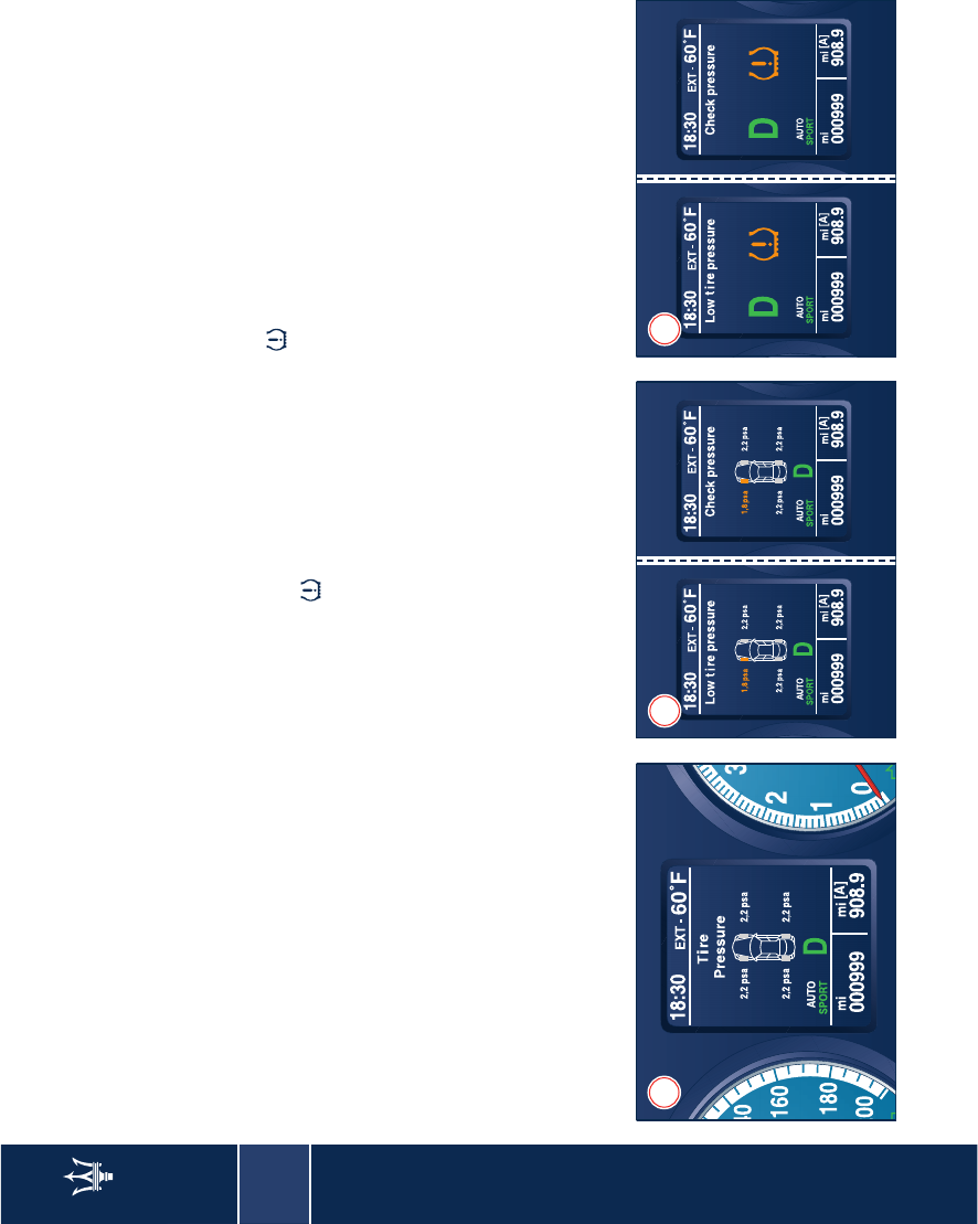
Normal conditions
By pressing the specific button for
quick information display ("Mode"
button pressed briefly), the user can
access the information page (screen
page 1), which displays the pressure
levels for each tire.
Low pressure
When the on-board instrument panel
receives a message from the tire
pressure ECU indicating that one or
more tires have pressure levels below
the control threshold, screen pages 2
will alternate for 20 seconds on the
display. After this interval, the system
will display only the amber color
warning light .
After 10 minutes, the warning cycle
displays screen pages 2 for other 5
seconds. Upon the following key-on, if
the malfunction persists, the display
will alternate, once again, between
screen pages 2.
It may happen that the system does
not know what wheel is originating
the malfunction indication and
therefore is not capable of specifying
the wheel involved. In this case, screen
pages 3 will alternate on the display
for 20 seconds.
Subsequently, the amber color symbol
will be displayed in the area
dedicated to the warning lights, until
the correct situation is restored.
12 3

2
Tire pressure monitoring system (optional) 45
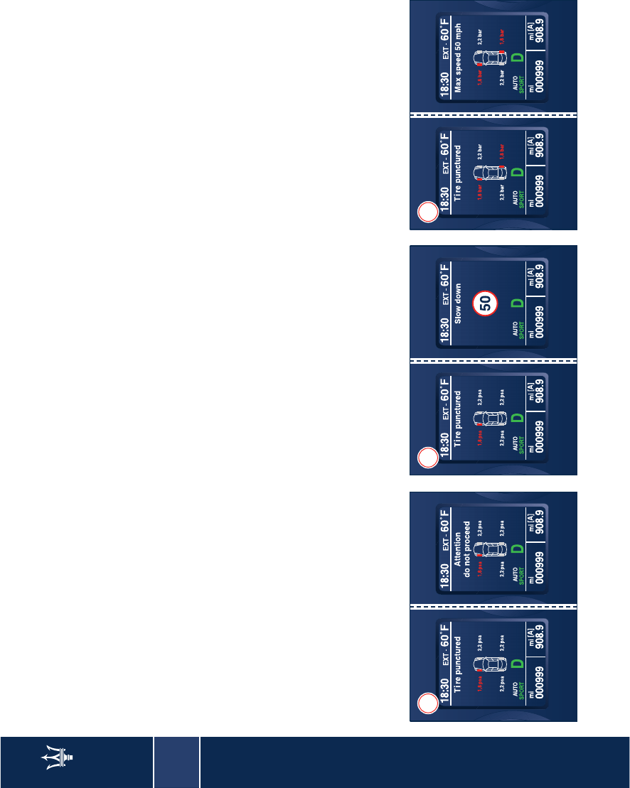
Tire punctures
When the tire pressure ECU informs
the on-board control panel that the
pressure level of one or more tires is
below the alarm threshold, screen
pages 4 will alternate on the display.
The malfunction is displayed following
the same logic as for the other
malfunctions with hw priority level,
until the correct situation is restored
and the system is calibrated again, as
required by the system itself.
It may happen that the system does
not know what wheel is originating
the malfunction indication and
therefore is not capable of specifying
the wheel involved. In this case, screen
pages 5 will alternate on the display.
Subsequently, the red color symbol
will be displayed in the area dedicated
to the warning lights, until the correct
situation is restored.
“Run Flat” tire puncture
If the vehicle is equipped with Run Flat
type tires, in the event of a tire
puncture screen pages 6 will alternate
on the display for 20 seconds.
The system calculates the residual tire
life in miles (or km) and repeats the
display cycle a first time after 31 mi (50
km) and a second time after 62 mi (100
km) driving.
4 5 6
2
46 Tire pressure monitoring system (optional)
During the “tire punctured” condition,
if more than 75 mi (120 km) are
traveled or if the vehicle speed exceeds
50 mph (80 km/h), screen pages 7 or 8,
respectively, are displayed according to
the above described logic.
If another tire is punctured, the system
calculates (without displaying it) the
updated value of the miles (km) that
can still be driven, depending on the
distance covered from the previous
puncture, and displays screen pages 9
alternately.
If in the meantime the control panel is
switched off, the next time the key is
turned to ON, the screen page
indicating that the system is not
calibrated will be displayed.
If the driver presses the MODE button
with "Escape" function, with a tire
punctured and the vehicle not running
at the max. speed - provided the tires
are still in the condition to continue
driving - the summary symbol will be
displayed in the dedicated warning
light area, until the correct condition is
restored and after subsequent
calibration requested by the system.
7 8 9
2
Tire pressure monitoring system (optional) 47
It may occur that the system does not
know which wheel is signaling the
fault and it is hence unable to display
it: screen pages 10 will alternately
appear on the display for 20 seconds.
The system calculates the residual tire
life and repeats the display cycle a first
time after 31 mi (50 km) and a second
time after 62 mi (100 km) driving. It
also monitors that the max. miles (km)
driven or the permitted speed is not
exceeded in these conditions.
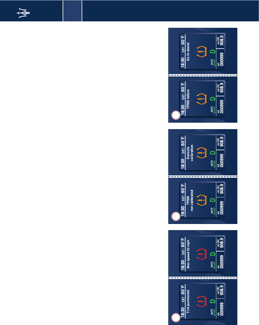
System not calibrated
If the system has not been calibrated
or following a tire replacement, screen
pages 11 will alternate on the display.
Subsequently, the screen page with the
icon symbol will be displayed once
again in the area dedicated to the
warning lights.
The system can be calibrated by means
of the specific button (see page 42).
Tire pressure monitoring system
failure
Screen pages 12 alternate in the
following cases:
• malfunction in the circuit and/or
wiring leading to the ECU;
• no signal reception by one or more
sensors due to malfunction,
breakage or flat battery;
• ECU malfunction.
The display sequence follows the usual
logic of malfunctions. Therefore, after
10 seconds, the symbol will appear in
the dedicated area.
10 11 12
2
48 Tire pressure monitoring system (optional)
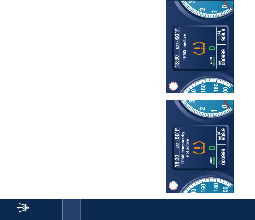
System temporarily not active
When one of the following conditions
arises:
• excessively high temperature;
• during the first calibration
procedure;
screen page 13 will appear.
System not active
After Key-on, in the case that the
system has been deactivated by means
of the diagnosis tester, screen page 14
will appear for several seconds.
13 14
2
Parking sensors (optional) 49
Parking sensors
(optional)
During parking maneuvers, the
parking sensors are designed to
provide the driver with information on
the distance between obstacles found
in front or behind the vehicle.
The driver is informed of the presence
and of the distance of any obstacle by
means of acoustic signals (beeps).
By supplementing his/her direct visual
information with that provided by the
system's acoustic signals, the driver can
avoid potential collisions.
The driver is fully responsible
for parking and other
potentially dangerous
manoeuvres. The system has actually
been designed only as a
supplementary aid during parking
manoeuvers, since it helps the driver
to detect obstacles outside his/her
field of vision.
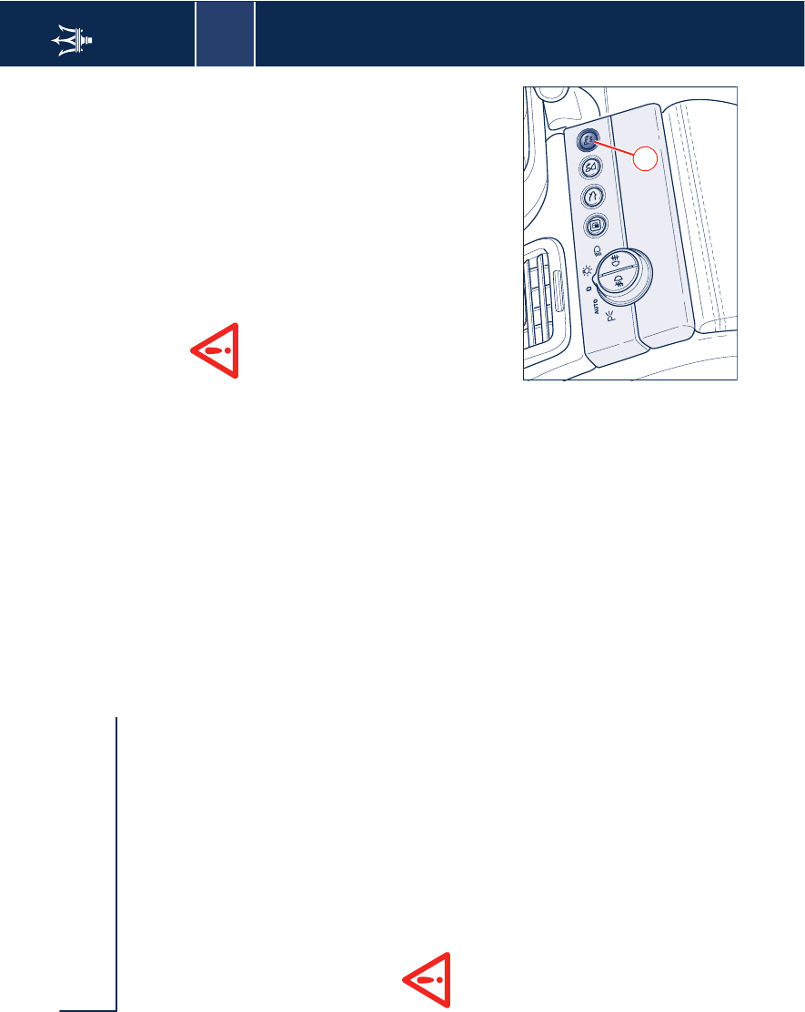
The front and rear sensors for the
parking system are housed in the
bumper. The rear sensors are activated
automatically with the key turned to
MAR, when the reverse gear is
engaged, whilst the front sensors can
be activated by pressing button A on
the dashboard, on the left of the
steering wheel. When the front
sensors are active, the button LED
turns on. To cut out the sensors, press
button A once again.
By disengaging the reverse gear, the
rear sensors will deactivate, while the
front sensors will remain active until a
speed of approx. 9.5 mph (15 km/h) is
exceeded.
When the sensors are activated, the
system begins to beep as soon as an
obstacle is detected, and the tone
frequency increases as the vehicle
approaches the obstacle. When the
obstacle is located at a distance of less
than 12 in (30 cm), the beep is
continuous. The signal stops
immediately if the distance from the
obstacle increases. The tone cycle is
constant if the distance measured by
the central sensors remains unaltered,
while if this occurs with the side
sensors, the signal stops after
approximately 3 seconds, to prevent
for example continuous beeps in the
event of maneuvers alongside walls.
Sensors
To measure the distance from the
obstacles, the system uses 4 sensors
fitted in the front bumper and 4
sensors fitted in the rear one.
For the system to operate
correctly, the sensors
positioned on the bumper
must be kept clean (remove any mud,
dirt, snow or ice).
WARNING: Should you need to repaint
the bumper or in case of paint touch-
ups in the sensors' area, please contact
exclusively your local Authorized
Maserati Dealer. Incorrect painting/
touch-ups could jeopardize the
parking sensors' operation.
A
2
50 Parking sensors (optional)
WARNING: When cleaning the sensors,
take special care not to scratch or
damage them; therefore, do not use
dry, rough or hard cloths. The sensors
must be washed with clean water,
possibly with car shampoo added. In
car-washes which use steam jet or high
pressure cleaning machines, keep the
nozzle at least 4 in. (10 cm) away from
the sensors.
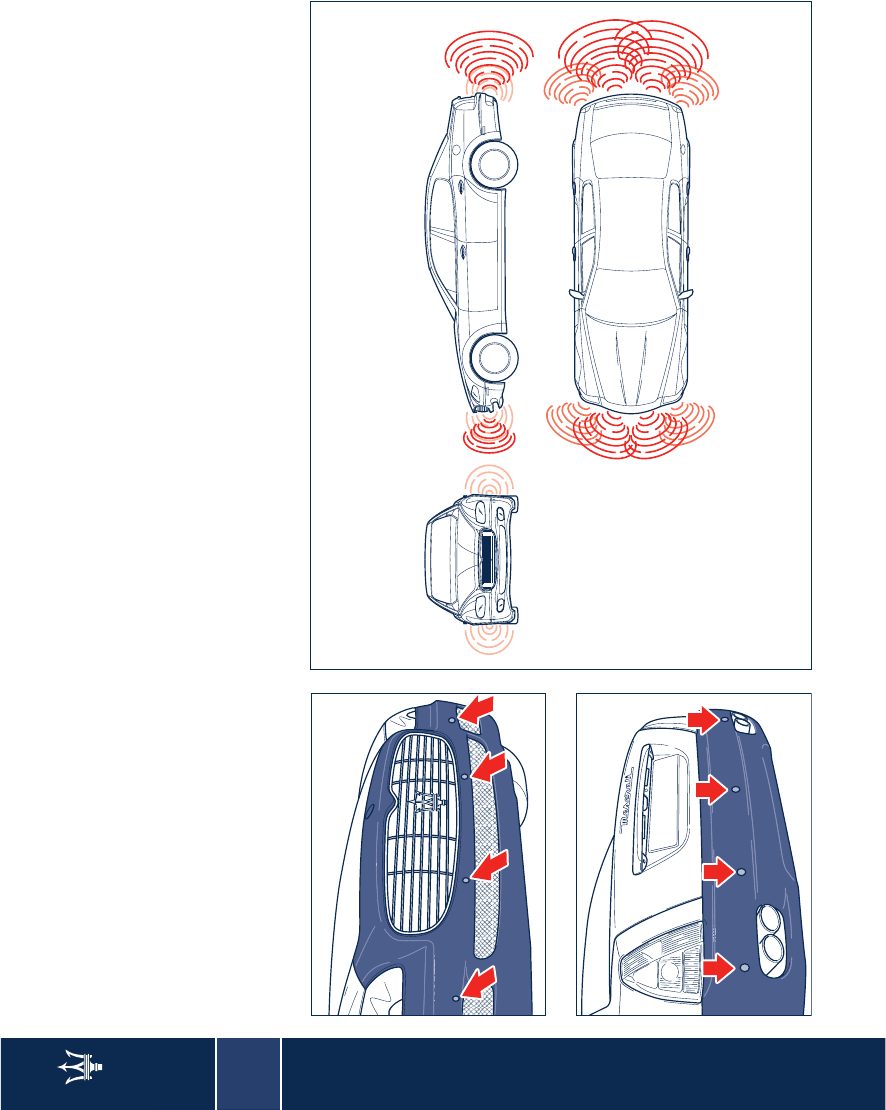
Sensor range
The sensors allow the system to
monitor the front and rear of the
vehicle.
In fact, their position covers the central
and lateral zones at the front and at
the rear of the vehicle.
If the obstacle is located in the central
area, this is detected at distances of
less than 35 in. (0.9 m) (front) and 59
in. (1.50 m) (rear). If the obstacle is
located in a lateral position, it will be
detected at distances of less than 24 in
(0.6 m).
2
Parking sensors (optional) 51
Failure indicators
The ECU checks all of the system
components every time the ignition
key is turned to MAR. The sensors and
the respective electric connections are
then constantly monitored throughout
the the system operation.
The failure of the parking system
sensors is indicated by the symbol
that switches on on the multi-function
display accompanied by the message
"Parking Sensors Failure".
In the event of a failure signal, stop the
vehicle and turn the ignition key to the
Stop position. Try to clean the sensors
and make sure that you are not near
ultrasound emitting sources (e.g. truck
pneumatic brakes or pneumatic
hammers). If the cause that originated
the malfunction has been removed by
turning the key back to MAR the
system will start working fully
efficiently once again and the failure
symbol on the multi-function display
with the relative message will turn off.
If, instead, the warning light remains
lit, contact your local Authorized
Maserati Dealer to have the system
checked, even if it is still working.
As a matter of fact, if the failure
detected by the ECU does not
jeopardize its operation, the system
will continue working but the
malfunction will be stored so as to be
checked by your local Authorized
Maserati Dealer upon a subsequent
inspection.
WARNING: During parking
manoeuvres, always take the utmost
care over obstacles that could be
located above or underneath the
sensors. In fact, in certain
circumstances, objects located near the
rear of the vehicle are not detected by
the system and therefore could
damage the vehicle or be damaged
themselves.
WARNING: The signals transmitted by
the sensors can also be altered by
damage to the sensors or by dirt, snow
or ice on the latter or even by
ultrasound systems (e.g. pneumatic
truck brakes or pneumatic hammers) in
the vicinity.
The driver is fully responsible
for parking and other
potentially dangerous
maneuvers. During these maneuvers,
always make sure there are no people
(especially children) or animals in the
maneuvering area. The parking
sensors must be considered an aid for
the driver who, in any case, must
never take less care during potentially
dangerous manoeuvres, even if they
are carried out at low speeds.
2
52 Fuel cut-out inertia switch
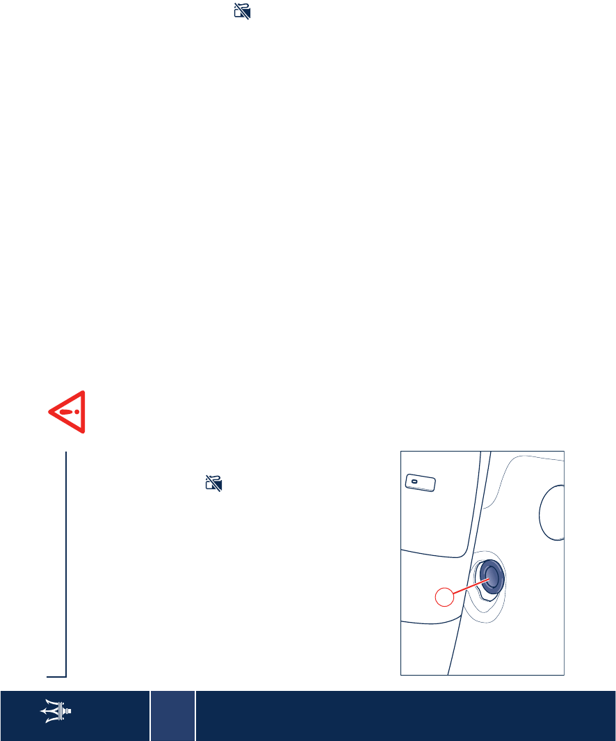
Fuel cut-out inertia switch
The vehicle is equipped with a safety
switch which is designed to intervene
in the event of a collision, cutting off
the fuel supply and consequently
causing the engine to stop. It also
prevents fuel leakage if the fuel lines
are damaged during the accident.
The intervention of the safety switch is
indicated by the warning light
coming up on the instrument panel.
The switch is positioned underneath
the front left-hand seat.
After impact, if you smell fuel
or note any leakage from the
fuel supply system, do not
reactivate the switch to help prevent
any risk of fire.
The activation of the inertia switch
results in all the doors and the luggage
compartment unlocking and in the
internal dome lamp and the four
direction indicators switching on.
Resetting the switch
Turn the ignition key to the STOP
position.
Check that there is no leakage from
the fuel system.
If no leaks are found, reset the inertia
switch which stops the fuel pump
operation, by pressing button A on the
switch.
Turn the ignition key to the MAR
position, wait a few seconds and then
move it to the ACC. position.
Check that the warning light on
the instrument panel is switched off.
Check once again that there are no
fuel leaks.
A

3
53
Instruments and controls
Dashboard 54
Instrument panel 60
Indicators and warning lights 61
Instruments and gauges 67
Controls 72
Internal outfits 78
3
54 Dashboard
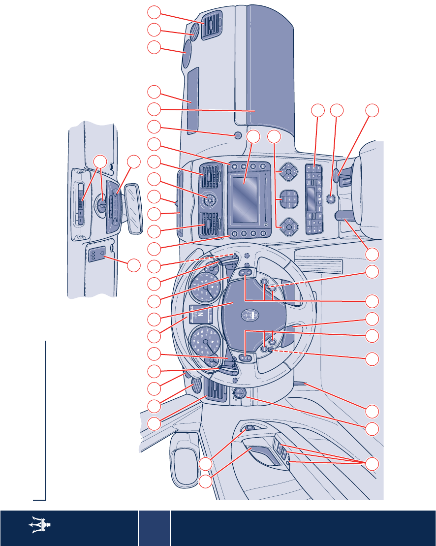
Dashboard
1 2
34 33
3 4 5 6 87 9 10 11 12 13 14 15 12
3637
35
16 17 18 19
32 31 30 2829 27 27 26 25 24
23
22
20
21
321

3
Dashboard 55
1) Air conditioning and heating system
vents
2) Side windows vents
3) Speaker
4) DOWN-gearshift lever
5) Cruise Control, Direction indicators
control lever
6) Instrument panel
7) Driver’s airbag and horn
8) Windshield/headlight wiper/washer
control lever
9) UP-gearshift lever
10) Controls to the right of the steering
wheel
11) Side buttons, to the left of the
Multi Media System Display
12) Central air-conditioning and
heating system vents
13) Upper air conditioning and heating
system vent
14) Sun radiation sensor
15) Clock
16) Side buttons, to the right of the
Multi Media System Display
17) Glove compartment opening
button
18) Glove compartment
19) Passenger’s airbag
20) Multi Media System Display
21) Multi Media System Controls
22) Air conditioning and heating
system controls
23) Hazard button
24) Joystick for shifting to 1st and
reverse gears
25) Handbrake lever
26) Ignition/steering lock switch
27) Multi Media System Controls
repeated on the steering wheel
28) CD-changer compartment
29) Steering wheel height and depth
adjustment control
30) Engine compartment lid opening
lever
31) Controls to the left of the steering
wheel
32) Controls on driver's door
33) External rear-view mirror controls
34) Internal door opening handle
35) Roof controls
36) Front dome lamp
37) Home link
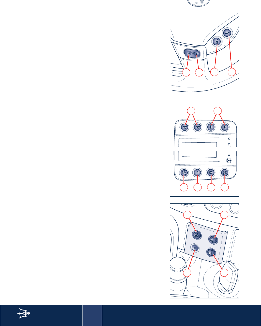
3
56 Dashboard
Ref.10 Controls to the right of the
steering wheel
A - Audio Pilot Sensor (see page 136)
B - Instrument panel brightness
increase
C - Instrument panel brightness
decrease
D - Trip and odometer reset control.
Ref. 11 and 16 Side buttons on the
Multi Media System display
A - gearbox deactivation button
B - SPORT mode button
C - Low grip function button
D - MSP System deactivation button
E - Door lock/unlock button
F - Sunshade raising/lowering button.
Ref. 27 Multi Media System Controls
repeated on the steering wheel
A - Increases the sound volume.
B - Decreases the sound volume.
C - Activates the guiding voice during
the trip navigation, and shows the
information pertaining to the
navigation session.
D - Calling the telephone number set;
accepting an incoming telephone
call; ending a telephone call in
progress by keeping the "refuse
incoming call" button pressed
down.
B
C
D
AA
B
C
D
E
F
B
A
C
D
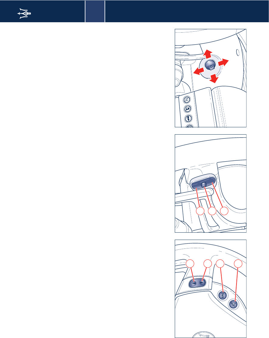
3
Dashboard 57
E - Radio mode: search for the first
tunable station with a higher
frequency; CD mode: next track
selection.
F - Radio mode: search for the first
tunable station with a lower
frequency; CD mode: previous track
selection.
G - Operating mode selection: FM, FM
TS, AM, AM TS, CD-C.
H - Mute function on/off.
I - Radio mode: recalling of stored
stations in increasing order; CD
mode: next CD selection;
Telephone mode: selection of
menu functions up.
J - Radio mode: recalling of stored
stations in decreasing order; CD
mode: last CD selection; Telephone
mode: selection of menu functions
down.
K - Displaying the navigation maps
Ref. 29 Steering wheel height and
depth adjustment control
E
F
G
H
I
K
J
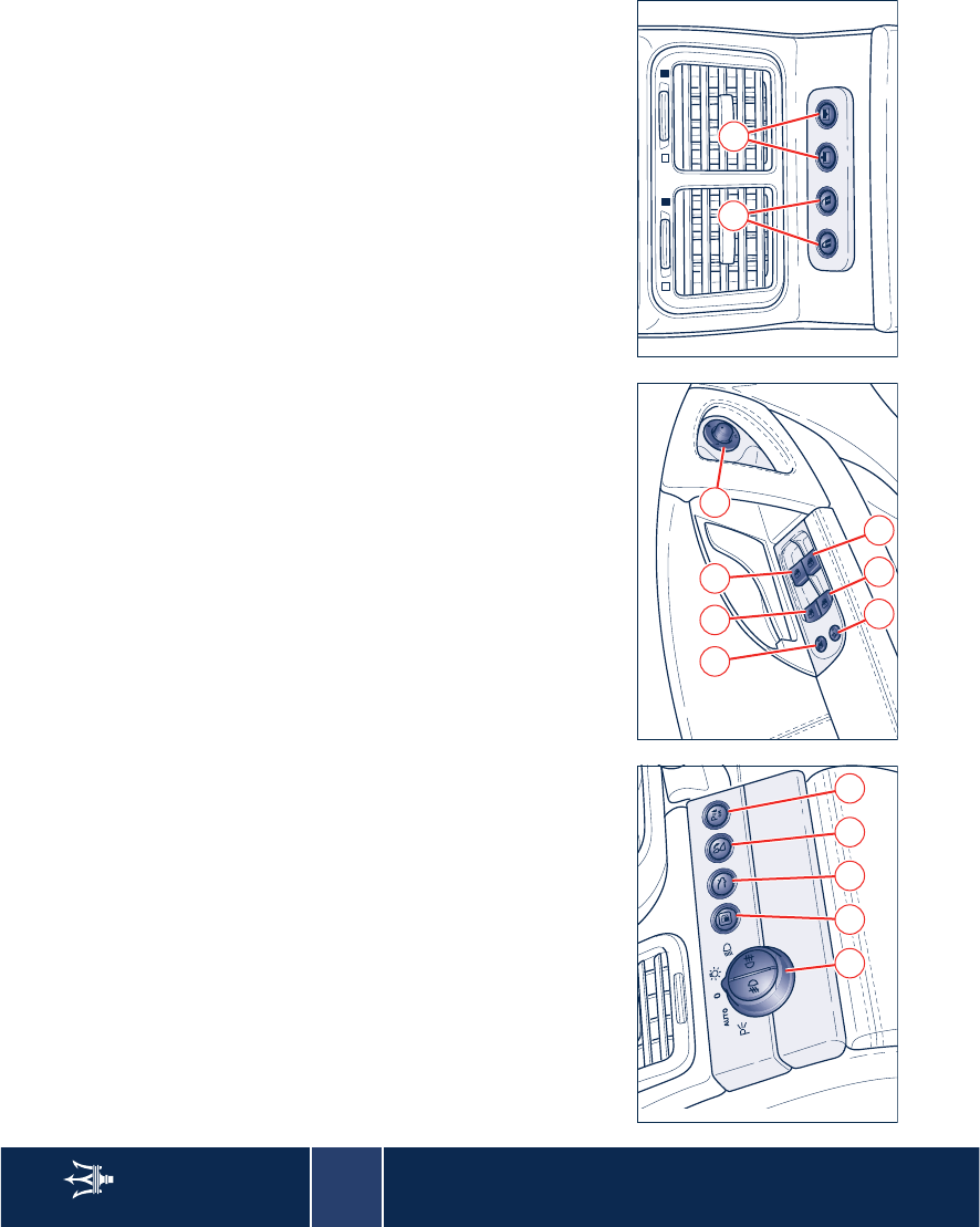
3
58 Dashboard
Ref. 32 Controls to the left of the
steering wheel
A - Light switch
B - Fuel tank flap opening button
C - Luggage compartment lid opening
button
D - Rear central headrest tilting button
E - Front parking sensors activation.
Ref. 33 Controls on driver's door
A - Rear power windows lock/unlock
button
B - EASY ENTRY activation/
deactivation
C - Rear left-hand power window
control
D - Rear right-hand power window
control
E - Front left-hand power window
control
F - Front right-hand power window
control
G - External rear-view mirror
adjustment control.
Rear tunnel controls
A - Door lock/unlock buttons
B - Sunshade raising/lowering buttons
A B C D E
E GC
FDB
AAB
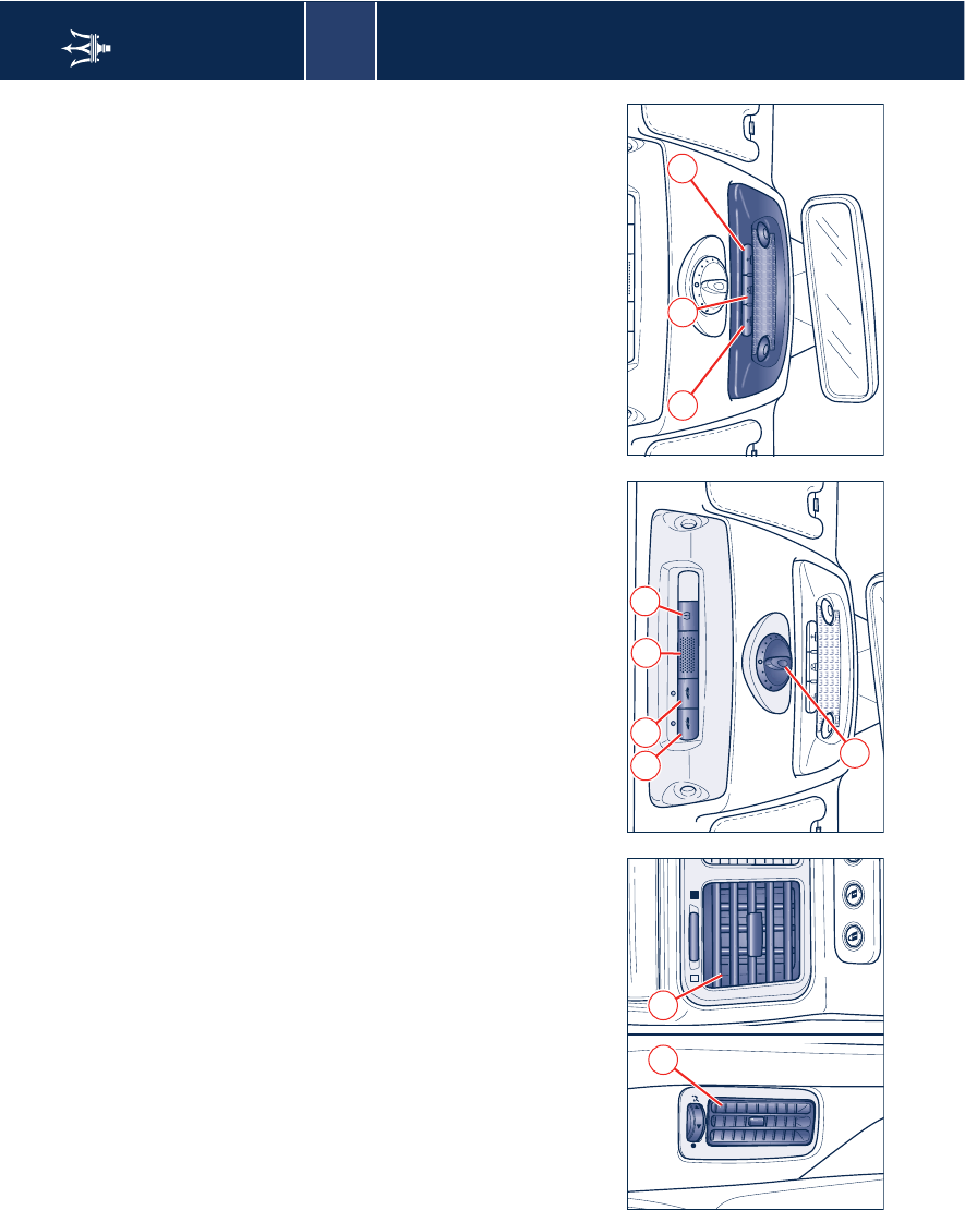
3
Dashboard 59
Rear vents
A - Central vents on tunnel
B - Side vents on pillars
Ref. 36 Roof controls
A - Alarm system motion sensors cut-
out
B - Alarm system anti-lift feature cut-
out
C - Telephone handsfree microphone
D - Tire pressure calibration control
E - Sunroof opening/closing control
Ref. 37 Controls on front dome lamp
fixture
F - LH side light switch
G - Central light switch
H - RH side light switch.
AB
E
A B CD
H
F G
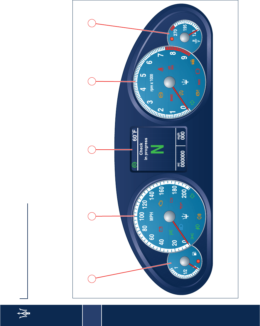
3
60 Instrument panel
Instrument panel
1) Fuel level gauge and low fuel
warning light
2) Speedometer with total and trip
odometer
3) Display
4) Tachometer
5) Coolant temperature gauge and
high temperature warning light
1 2 3 4 5
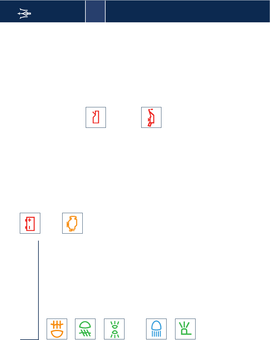
3
Indicators and warning lights 61
Indicators and warning
lights
Rear fog lights
When the rear fog lights are
turned on.
Fog lights
When the fog lights are
turned on.
Position lights/low
beams
This switches on when the
position lights, low beams or parking
lights are turned on.
High beams
When the high beams are
turned on or flashing.
Parking lights
With the key removed, this
indicates the parking lights
are turned on.
Alternator failure (*)
If there is a fault in the
recharging system.
When the battery is insufficiently
charged or overcharged (flashing).
Engine diagnosis system
failure (OBDII)
Under normal conditions, this
warning light should switch on when
the ignition key is turned to the MAR
position, and should turn off 18
seconds after engine starts. This will
show that the warning light is working
properly.
If the warning light remains on or
switches on while driving, it indicates
that there is a failure in the fuel supply/
ignition and emission control systems.
The failure could cause high exhaust
emissions, loss of performance, poor
vehicle handling and high consumption
levels.
In these conditions you can drive
slowly without demanding engine
performance or high speeds.
Prolonged use of the vehicle when the
warning light is on can cause damages.
For this reason, you should contact
your local Authorized Maserati Dealer
as soon as possible. The warning light
will go out if the problem disappears.
The error will be stored by the system
in any case.
WARNING: When the ignition key is
turned to the MAR position, if the
warning light UU
UU does not switch on
or if it switches on while driving,
contact your local Authorized Maserati
Dealer as soon as possible.
DuoSelect gearbox
failure (*)
If the failure still permits it,
free the road and contact your local
Authorized Maserati Dealer.
Flashing warning light: low pressure in
the system.
Low oil pressure (*)
Under normal conditions, the
warning light should switch
on when the ignition key is turned to
the MAR position and switch off as
soon as the engine is started.
If the warning light remains on or
turns on while driving, this indicates a
too low engine oil pressure. In this
case, turn the engine off immediately
and carry out the necessary checks.
If the problem persists, contact your
local Authorized Maserati Dealer.
3
62 Indicators and warning lights
Low brake fluid warning
light (*)
This switches on when the
brake fluid level drops below the
minimum level. The operation of the
warning light can be checked by
pressing the button on the brake fluid
tank cap located in the engine
compartment.
If the warning light comes on
while driving, check the brake
fluid level immediately. If the
fluid level is below the minimum level
there could be a leakage in the circuit:
in this case, contact your local
Authorized Maserati Dealer before
continuing your trip.
Defective wheel anti-lock
system (ABS) (*)
This switches on when the
ABS system is inefficient. The normal
brake system remains operational, but
it is advisable to contact your local
Authorized Maserati Dealer as soon as
possible.
Seat belts (*)
This switches on when the
driver’s seat belt is not
fastened or fastened improperly. A
buzzer is also activated for
approximately 8 seconds when the
light is on.
Airbag/pre-tensioner
failure (*)
This turns on to indicate that
the pre-tensioner and/or airbag system
is/are inefficient.
Turning the key to MAR, the
light comes on but it should
go out after a few seconds
with the engine running.
If the warning light stays on
or if it does not come on, or if
it comes on while driving,
stop immediately and consult your
local Authorized Maserati Dealer.
Maserati CODE (*)
When the ignition key is
turned to MAR, the warning
light switches on in three different
ways:
– One flash - key code acknowledged.
The engine can be started.
– Permanently lit - key code not
acknowledged. To start the engine,
follow the emergency starting
procedure as specified in the section
"In an emergency", after having
attempted to start it with other keys.
– Flashing light - vehicle not protected
by the Maserati CODE system. The
engine can, however, be started but
contact your local Authorized
Maserati Dealer as soon as possible
since the vehicle is not protected
against theft attempts.

3
Indicators and warning lights 63
Brake pads worn (*)
This lights up when the front
brake pads have reached the
wear limit.
Contact your local Authorized
Maserati Dealer.
Handbrake engaged (*)
The warning light comes on
when the handbrake is
operated.
Handbrake failure
This indicates that the
handbrake system is
inefficient.
MSP system failure (*)
This indicates a malfunction
or the deactivation of the
MSP system.
(*) Viewed on the display as well
Right-hand direction
indicators
This lights up when the right-
hand direction indicators or the hazard
lights are turned on.
Left-hand direction
indicators
This lights up when the left-
hand direction indicators or the hazard
lights are turned on.
3
64 Indicators and warning lights
Warning lights on the display
Inertia switch, fuel cut-
out enabled
This switches on when a
collision triggers the inertia switch,
thus cutting off the fuel supply.
After impact, if fuel is smelt or
leakage is noted from the fuel
system, do not reactivate the
switch in order to help prevent the risk
of fire.
Windshield washer fluid
This signals a low level of
washer fluid in the
windscreen washer tank.
Cruise Control
This indicates that the
constant speed regulator,
Cruise Control is active.
Lights failure
This switches on in the case of
a system failure or burning-
out of the bulbs for the position,
direction indicators or rear fog lights.
License plate lights
failure
This switches on in the case of
a system failure or burning-out of the
number plate lights bulb.
Stop lights failure
This switches on in the case of
a system failure or burning-
out of the stop lights bulb.
Twilight sensor failure
This switches on in the case of
a failure of the twilight
sensor.
Too high catalytic
converter temperature
This warning light starts
flashing or comes on permanently
when engine failure results in high
exhaust system temperature.
IF THE WARNING LIGHT IS
FLASHING: the catalytic
converters' temperature is too
high. Slow down immediately until
the warning light goes out.
IF THE WARNING LIGHT TURNS
ON PERMANENTLY: the
catalytic converter
temperature is at a dangerous level
and the catalytic converters
themselves may be damaged. Slow
down immediately until it turns off,
and slowly drive to the nearest service
centre.
WARNING: If the light turns on
permanently 3 times the engine will
stop.
Will be possible to restart only by key-
off - key-on and recarsi lentamente in
officina.
Maserati declines all
responsibility for whatever
damage deriving from non
compliance with the above mentioned
warnings.
3
Indicators and warning lights 65
Power steering failure
This indicates a fault in the
power steering system.
Slowly drive to the nearest Maserati
Service Centre paying attention to
stiffening of the steering.
DuoSelect gearbox oil
level
The red icon indicates that
the DuoSelect gearbox oil level is too
low.
Stop driving and contact your local
Authorized Maserati Dealer to have
the vehicle checked over.
Electronic Brakeforce
Distributor (EBD)
warning light
This lights up when the EBD
system is inefficient. In this case,
abrupt braking can cause early locking
of the rear wheels and possible side
skidding of the vehicle. Drive with the
utmost care and consult your local
Authorized Maserati Dealer
immediately.
Headlight aiming system
failure
This indicates that the
automatic system for aiming the
headlights is faulty.
ASR system failure
This indicates the
deactivation or failure of the
ASR system.
In the event of a failure, contact your
local Authorized Maserati Dealer.
ASR system activation
This indicates that the ASR
system has tripped.
Rain sensor failure
This indicates that the rain
sensor is faulty.
Contact your local Authorized
Maserati Dealer.
Parking sensors failure
This indicates a failure in the
parking sensors system.
Shock absorber failure
When driving, it indicates a
malfunction in the suspension
system.
Slowly drive to the nearest Maserati
Service Centre paying attention to
stiffening of the steering.
Finger-trap prevention
system failure
This indicates a failure in the
windows’ finger-trap prevention
system.
Before and during activation
of the power window, always
check that the passengers are
not exposed to the risk of injury both
by the moving window and by
personal objects dragged or hit by it.
Generic failure
This indicates a malfunction.
The degree of the latter is
specified in the relative text.
3
66 Indicators and warning lights
MSP system failure
This indicates the
deactivation or failure of the
MSP system.
MSP system activation
This indicates that the MSP
system has tripped.
Tire pressure
This warning light is
connected to the tire pressure
monitoring system (see page 42).
When the icon is red, stop the
vehicle and contact your local
Maserati Dealer. If Run Flat
tires are fitted on the vehicle, drive
slowly to the nearest Maserati Service
Centre.
Doors and lids open
This indicates that the doors
or lids are open or improperly
closed: the part not closed is
highlighted in red.
WARNING: Before driving off, close
any open or not properly closed doors
and lids.
Ice hazard
This switches on when the
outside temperature is 37,4° F
(3° C) or lower, in order to indicate the
risk of icy roadbed. Under such
conditions, drive carefully and slow
down as the grip of the tires will prove
to be markedly reduced.
Do not activate the "SPORT"
mode in this situation.
Vehicle “SPORT” setting
When the button that sets
the vehicle to the "SPORT"
mode is pressed.
WARNING: The "SPORT" mode
changes the vehicle driving features.
Automatic gearbox
setting
This indicates that the
automatic gearbox feature is active.
"Low grip" function
This indicates that the low
grip function is active
Seat heating
This indicates that one or
more seats are being heated.
Scheduled maintenance
Depending on the
accompanying message, this
indicates that service schedule
deadlines are either approaching or
due on that day.
Upon reaching a deadline, contact
your local Authorized Maserati Dealer.
SPORT
AUTO
ICE
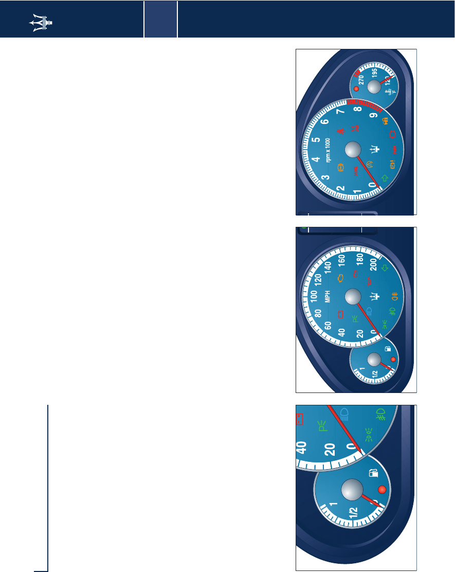
3
Instruments and gauges 67
Instruments and gauges
1 – Fuel level gauge
The lighting up of the warning light
inside the gauge indicates that there
are approx. 3.7 Us. gal (14 litres) of fuel
in the tank.
2 – Tachometer
It indicates the vehicle speed. The
gauge starts providing data when 2.5
mph (4 km/h) are exceeded.
4 – Tachometer
It indicates the engine's r.p.m. Correct
driving allows the driver to achieve
proper engine performance, without
the need of over-revving.
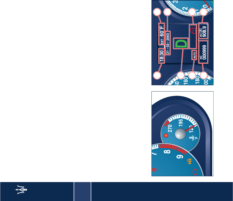
3
68 Instruments and gauges
5 - Coolant temperature gauge
It indicates the temperature of the
coolant. If the needle indicates high
temperatures and at the same time the
warning light switches on, stop the
vehicle immediately and have the
cooling system checked by your local
Authorized Maserati Dealer.
3 – Display
Incorporated in the instrument panel,
it performs the following functions:
– it provides general information
while driving;
– it signals of any failures and
warnings;
The user can interact with the system
by setting the parameters for the
information that can be recalled.
The screen page appearing on the
display following the initial check
cycle, in normal working conditions,
contains the following information:
A - Date
B - Time
C - Gear engaged
D - Driving mode
E - Total odometer,
F - Trip odometer A, B or vehicle speed
repetition.
G - Other symbols that may be
displayed in icon form
H - Outside temperature
From the set-up menu in the Multi
Media System, the user can also choose
to have the information displayed for
the Audio, Navigator and Telephone
repeated on the dashboard. For the
relevant procedures and instructions,
see the “Multi Media System” manual.
AIR
BAG
B H
A
C
G
D
EF
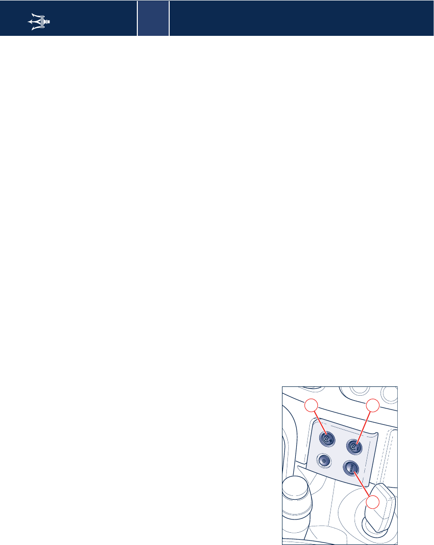
3
Instruments and gauges 69
Controls
MODE
The screen page activation and setting
is controlled by pressing the MODE (J),
“+” (K) and “-” (L) buttons.
Pressing the MODE button briefly will
switch to the following screens in
sequence:
– Trip A
– Trip B
– Tire pressure
– Option Selection.
Each of these has a 10-second timing,
after which the non-flashing
information previously viewed is
restored.
Pressing the MODE button for more
than 2 seconds the user will select the
Trip Odometer information currently
displayed, or the Trip Odometer A if
the tachometric repetition is active.
This piece of information will flash for
10 seconds, after which the non-
flashing information previously
viewed is restored.
“+ “ and “-”
By means of the “+ “(K) and “-” (L)
buttons, the user can adjust the
instrument panel brightness.
When the "Option Selection" screen
page is viewed, these buttons can be
used to select, choosing between Trip
Odometer A and Trip Odometer B, the
information to be repeated on the
display. In fact, by selecting , Odo A or
Odo B, with the MODE (J) button and
then pressing buttons “+ “ and “-”, the
user will display the trip information
selected (flashing) alternately.
Trip Odometer reset
In all these cases, and before the 10
seconds are up, pressing the MODE (J)
button briefly (less than 2 seconds) will
result in the trip information relating
to the flashing Odometer (A or B)
being reset.
Setting the date
The date can be set by means of the set
up menu of the Multi Media System
(see Multi Media System Manual).
K
L
J
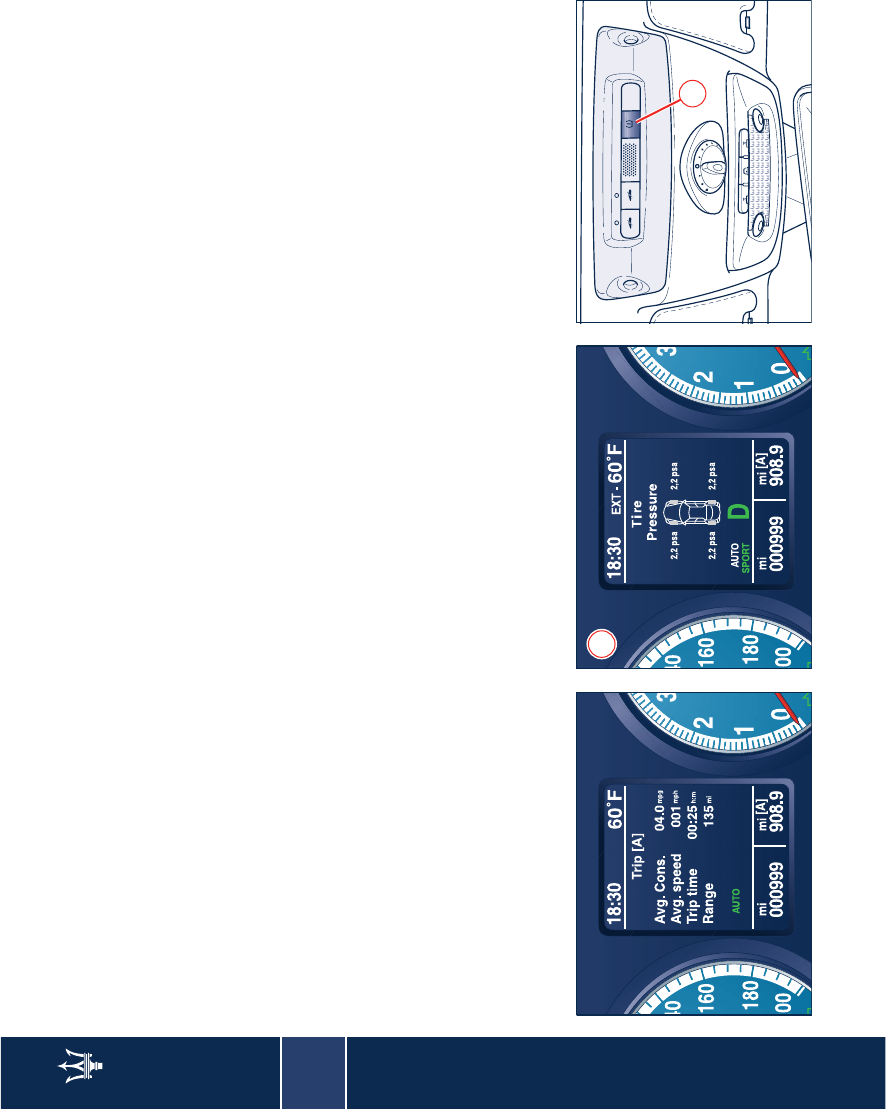
3
70 Instruments and gauges
TRIP screen page
The Trip screen page is recalled by
pressing the MODE (J) button. Each
TRIP screen page (A or B) is timed, i.e.,
it is displayed for a maximum of 10
seconds, after which the screen
previously active is restored.
When the TRIP A or TRIP B feature is
active, the following information is
viewed on the display:
– travelled distance (km - miles)
– average fuel consumption (km/L –
mpg)
– average travelling speed (km/h -
mph)
– trip time (hh:mm)
– fuel range (km - miles)
The unit of measurement can be set via
the set up menu of the Multi Media
System.
Tire pressure screen page
If the vehicle is equipped with the tire
pressure monitoring system (optional),
pressing the MODE (J) button the user
will display information about the
"Tire Pressure".
This screen page is displayed for 10
seconds and, in normal conditions, it
will appear as shown in figure 1
– furthermore, the system
acknowledges the following
conditions:
– system temporarily not active (es.
external radio interference)
– system not calibrated (e.g., a tire was
replaced)
– system failure
– system not active (if it is disabled by
the diagnostics system)
– low pressure or puncture in front LH,
front RH tires or rear LH and rear RH
tires
– low pressure or puncture in
unidentified tire.
The system can be calibrated by
pressing button M, on the front dome
light fixture. The initialisation of the
procedure is indicated on the display
by the message “Calibration started”.
For more information, please see the
“Tire pressure monitoring system”
chapter on page 42.
1
M

3
Instruments and gauges 71
Multi Media System set-up menu
By accessing the on-board Computer
mode (TRIP) the user can set the
vehicle configuration.
The settable parameters are the
following:
– Twilight Sensor's sensing range: 3
setting levels;
– Clock: time setting;
– Time mode: choose between the 0-
12 hour or 0-24 hour format;
– Date: day/month/year or month/day/
year format;
– Language: Italian, German, English
(metric or imperial), Spanish, French,
Dutch, U.S. English (metric or not
metric).
– Warning buzzer volume:
Buzzer volume setting;
– Unit of measurement: choose
between the following units of
measurement:
• temperature: ˚C, ˚F;
• distance: km, miles;
• consumption: litres/100km, km/litre,
mpgUK; mpgUS;
• tire pressure: bar - psi
– Repetition of instrument panel
information on the display:
repetition enabled/disabled;
– Door unlock: sets the following
functions:
• door and luggage compartment
locking upon exceeding 12.5 mph (20
km/h);
• only front driver's door unlocked or
all doors unlocked;
• luggage compartment lid unlocked
together with the doors.
– Easy Entry/Exit: feature enabled.
For more information, please see the
“Multi Media System” manual.
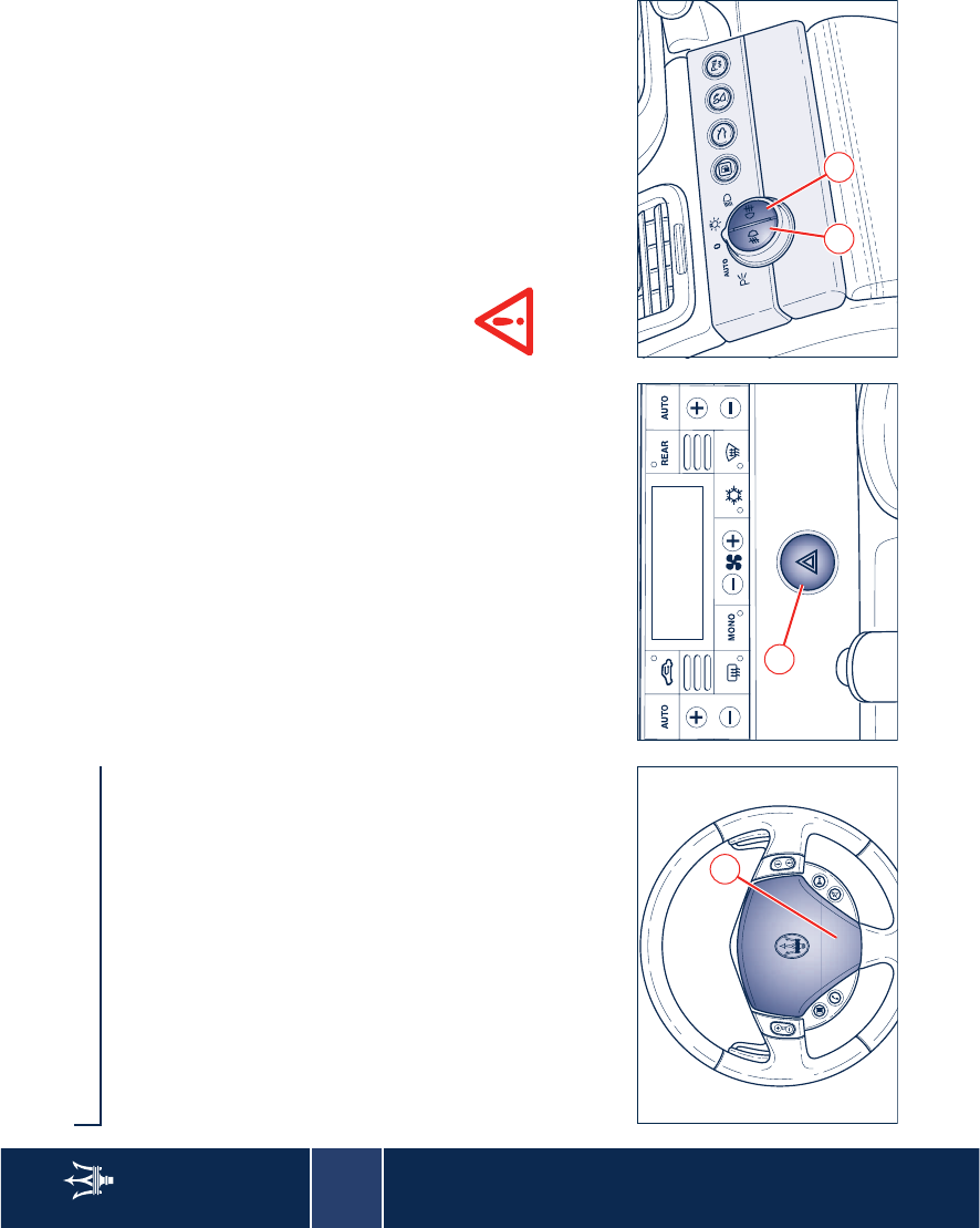
3
72 Controls
Controls
Horn
Pressing the horn symbol A, the horn is
activated.
Hazard warning lights
Press button B to turn on the hazard
warning lights. Their operation is
independent of the ignition key
position. Press the button again to turn
them off.
When these lights are on, the direction
indicators, the related warning lights
on the instrument panel and the
button are flashing.
WARNING: When the hazard warning
lights are activated, the direction
indicators control is disabled.
Controls to the left of the
steering wheel
Front fog lights
Press button C to switch on the front
fog lights. They only work with the
position lights or low beams on. The
LED on the button switches on when
the lights are on.
Rear fog lights
Press button D to switch on the rear
fog lights. They only work with the
front fog lights or low beams on. The
LED on the pushbutton switches on
when the lights are on.
Do not use the rear fog lights
in normal visibility conditions
to avoid dazzling vehicles
behind.
A
B
C D
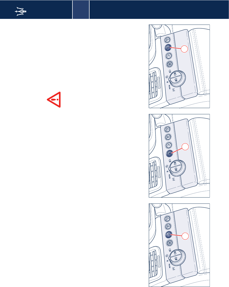
3
Controls 73
Opening the luggage compartment
Press button E to open the luggage
compartment lid.
This can be operated only with the
ignition key removed or turned to
STOP and ACC.
Vehicles are also equipped with a lever
inside the luggage compartment,
which permits opening from the
inside.
Opening the fuel tank flap
Press button F to open the fuel tank
flap on the rear right-hand side of the
vehicle.
This button can be operated only when
the ignition key is removed or in the
STOP position.
Rear central headrest tilting
Press button G to tilt the rear central
headrest. The headrest can be then
repositioned manually.
Before tilting the headrest,
always check that the
passengers are not exposed to
the risk of injury both by the moving
headrest and by personal objects hit
by it.
E F G
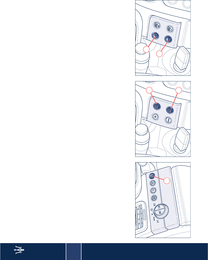
3
74 Controls
Deactivation the front parking
sensors
The front parking sensors can be
deactivated by pressing button H.
When these sensors are cut-out, the
LED on the button turns on. To
reactivate the sensors, press button H
again.
Controls to the right of the
steering wheel
Instrument panel display controls (see
page 69).
Setting the instruments and gauges'
brightness
With the external lights turned on,
press button J or K to increase or
decrease the brightness for the
instruments and gauges.
Mode
Pressing button L will select the screen
pages to be viewed on the instrument
panel display.
Audio Pilot Sensor
The sensor M detects the surrounding
noise and consequently adjusts the
stereo equalizer (see page 136).
H
J
K
L
M
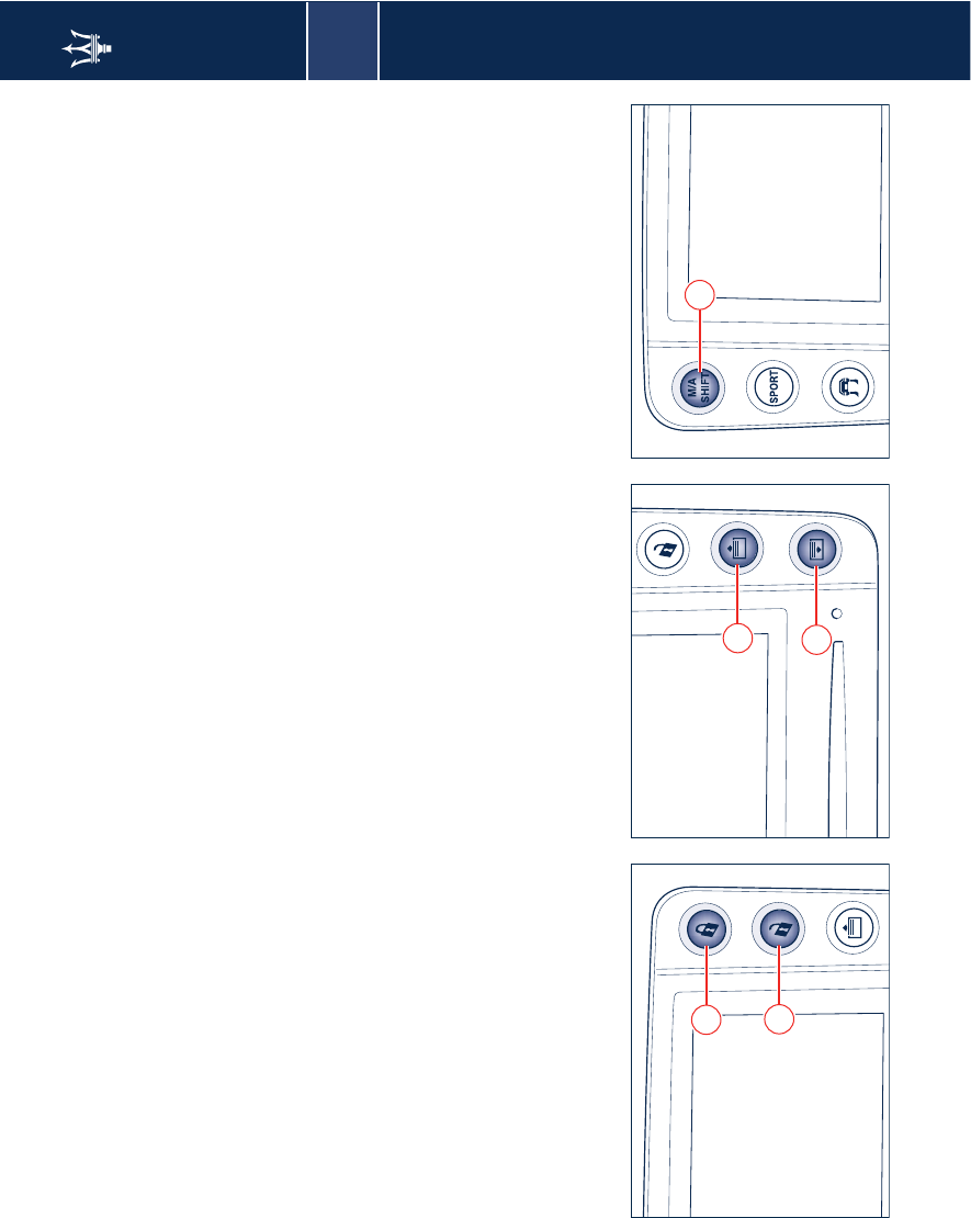
3
Controls 75
Side buttons on the Multi Media
System display
Lock set release and locking
Buttons N and O, on the front and rear
dashboards, control the locking and
unlocking of the lock sets respectively.
Sunshade movement
Press button P to raise the sunshade
and button Q to lower it.
The buttons are found both on the
front and on the rear dashboard.
WARNING: If the sunshade guide
needs to be cleaned with solvents, it
must then be greased in the area
where the sunshade slides using Teflon
based grease.
WARNING: If, within a time period of
25 seconds, the sunshades are raised
and lowered at least 4 times, the
relative control will disable them for 30
seconds. Before disabling the
sunshade, the system will complete the
movement in progress. The last
movement accepted will be opposite
to the starting movement.
WARNING: Before activating the
sunshade, make sure that there are no
objects that may interfere with its
travel.
DuoSelect Control
This is activated pressing switch R,
pressing the switch again will
deactivate it. The word AUTO will light
up on the display (see chapter
“DuoSelect” on page 142).
N
O
P
Q
R
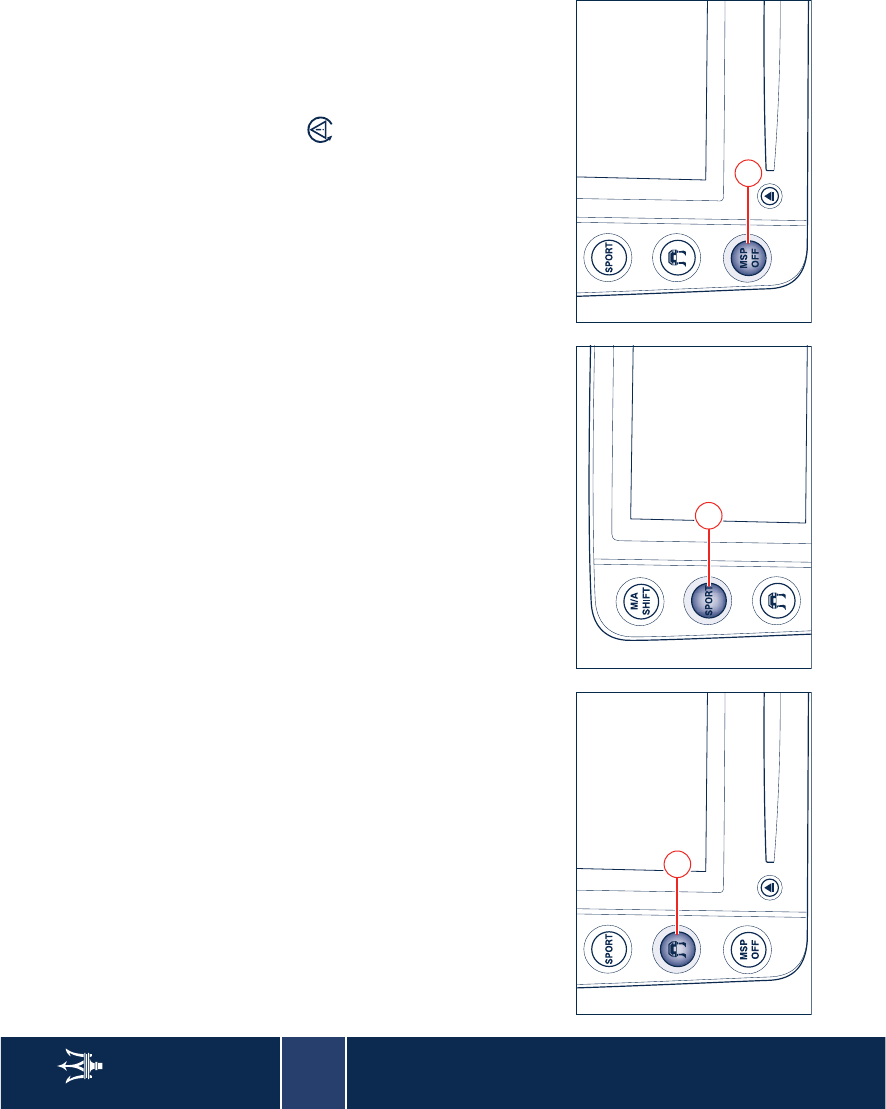
3
76 Controls
Low grip
This mode can be used on particularly
slippery roadbeds (snow, ice) and it is
activated/deactivated by pressing
switch S.
When the function is active, the word
ICE lights up on the display (see
chapter “Other system functions” on
page 147).
SPORT setting
Button T selects the SPORT mode,
which sets suspensions, traction
control and the "DuoSelect" gearbox
feature for a racing style driving.
Please notice that selecting the SPORT
mode will decrease driving comfort
markedly. Especially in city traffic and
on uneven road surfaces.
MSP System
The MSP system is designed to activate
automatically every time the engine is
started.
It is possible to disconnect or reconnect
the system while driving by pressing
button U. To avoid deactivating the
system inadvertently, the button must
be pressed for about 2 seconds to turn
the MSP system off.
When the system is deactivated, the
amber warning light on the
instrument panel lights up (see chapter
“MSP System” on page 38).
S
T
U
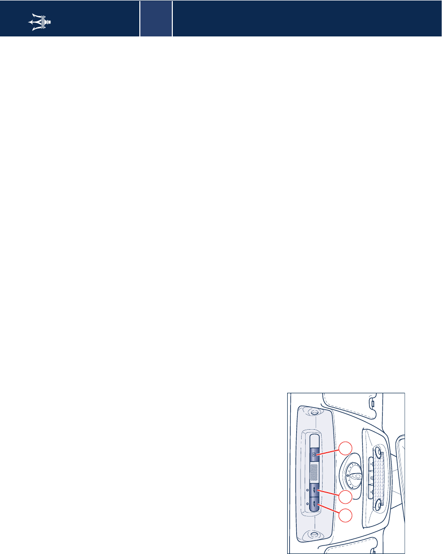
3
Controls 77
Roof controls
Deactivating the alarm system
motion sensors
Pressing button V will deactivate the
alarm motion sensing system. When
this function is deactivated, the LED on
the button will flash for 3 seconds and
then will turn off.
Deactivating the anti-lift alarm
system
Pressing button W will deactivate the
anti-lift alarm system. When this
function is deactivated, the led on the
button will flash for 3 seconds and
then turn off.
Tire calibration button
To calibrate the system, with the
ignition key in position MAR, press
button X for a time ranging from 4 to
10 seconds.
The system will take a maximum of 20
minutes to complete the calibration
procedure with the vehicle in motion.
The detected situation will then be
shown on the display.
For further information, see the “Tire
pressure monitoring system” on page
42.
V W X
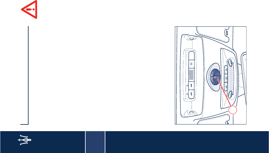
3
78 Internal outfits
Internal outfits
Sunroof (optional)
The sunroof is electrically controlled
and can only be operated with the
ignition key in the MAR position. It can
slide lengthways and be raised at the
rear (tilting).
The sunroof is equipped with a finger-
trap prevention system designed to
controls lengthways sliding when the
roof is being closed or tilted. If an
obstacle interferes with the roof travel
during the closing stage, the sunroof
stops and reverses its travel a short way
back.
WARNING: In the event of rain, always
close the sunroof to prevent the water
from staining the fabric/leather
upholstery.
Improper use of the sunroof
can however be dangerous,
even if the finger-trap
prevention system is fitted. Before and
during the sunroof operation, always
make sure that passengers are not
exposed to the risk of injuries caused
both by the moving roof and by
personal objects dragged or hit by the
sunroof itself. When you exit the
vehicle, always remove the ignition
key to avoid that the sunroof if
operated inadvertently, becomes a
danger for passengers remaining
onboard.
WARNING: Do not open the sunroof if
there is ice on it: risk of damage.
Opening and closing
The selector switch A controls all the
roof's movements.
There are 6 positions to open the
sliding roof lengthways and 3 three
positions for the tilted opening.
When the selector switch position has
been chosen, the sunroof moves until
it stops automatically in the position
chosen.
Upon opening the sunroof a front flap
rises automatically in order to deviate
the air flow.
WARNING: If the guide needs to be
cleaned with solvents, the
mechanisms, Bowden cables and
sliding parts, such as the water channel
slide, must be then greased.
A
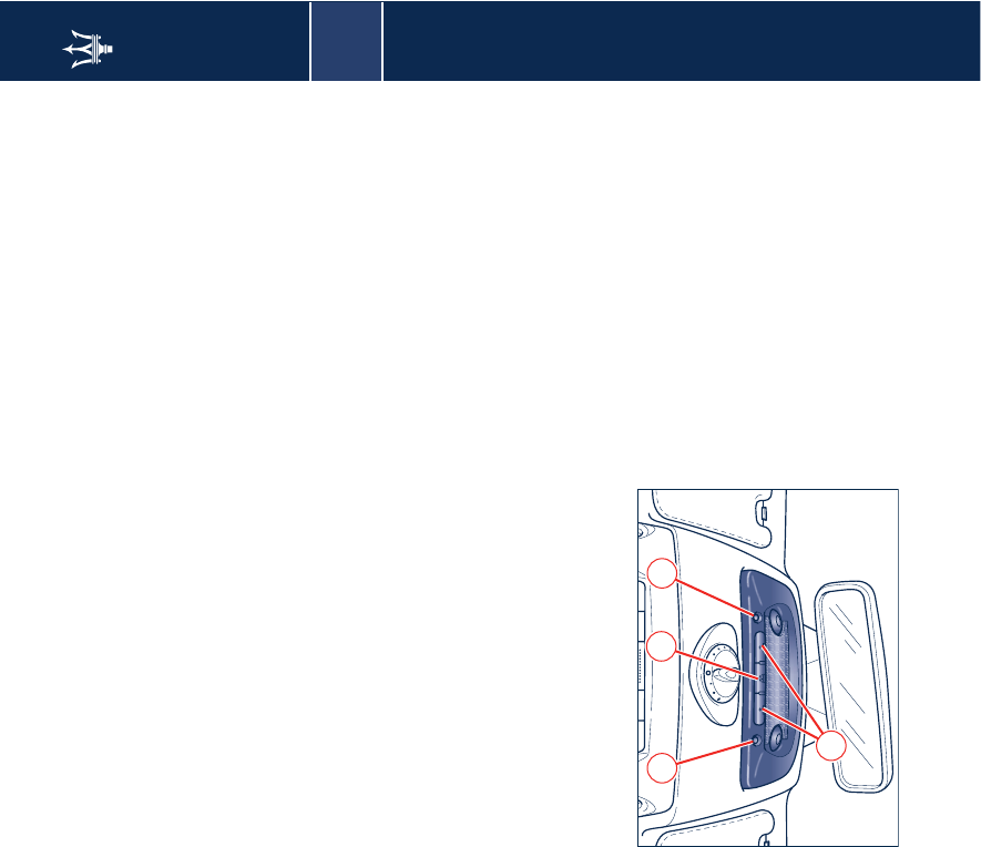
3
Internal outfits 79
System initialization
Following the battery disconnection or
the replacement of a specific fuse, the
finger-trap prevention system must be
initialized proceeding as follows:
– rotate selector switch A anti-
clockwise until reaching the limit
position, that is the maximum tilt
position.
– keep the selector switch pressed
down after the sunroof has stopped.
– release the selector switch
– within 5 seconds, press and keep the
selector switch pressed again
– the sunroof will start moving,
running a complete opening and
closing cycle and stopping in the
closed position: always keep the
selector switch pressed during this
stage
– release the selector waiting at least 2
seconds after the roof has stopped.
The system will start working normally
once again. If this is not the case,
contact your local Authorized Maserati
Dealer.
If the operation is interrupted before
its completion, repeat the procedure
from the beginning.
Periodically check that the water
draining holes in the roof
compartment are not clogged.
Front dome light
The dome light includes a central light
and two reading lights. The central
light, which turns on automatically
when one of the doors is opened and
turns off following the door closing
(timed switching off) may be switched
on manually by pressing button B.
The reading lights are controlled by
the respective buttons C.
If they are turned on pressing the
button, both the central and reading
lights will remain on for about 15
minutes after turning the engine off,
and then will turn off.
When the exterior lights are switched
on, the two night LEDs D light up.
Opening one or more doors, the front
and rear dome lights will turn on for
approx. 3 minutes. If the door is closed
before this time has elapsed, the lights
will switch off after about 10 seconds.
Upon removing the key from the
switch and activating the centralized
door lock with the remote control, the
dome lamps turn on for about 10
seconds.
In the event of a collision causing the
inertia switch to turn on, the dome
lights switch on automatically for
approx. 15 minutes.
B
D D
C
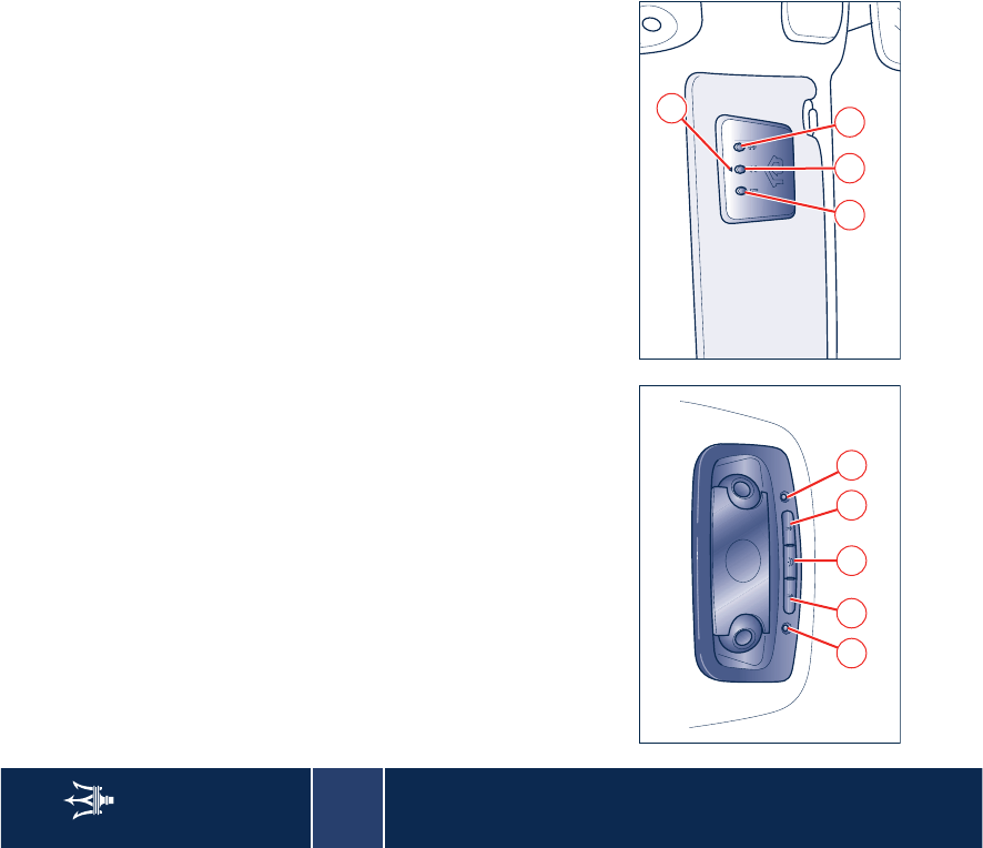
3
80 Internal outfits
Rear dome light
The dome light includes a central light
and two reading lights. The central
light, which turns on automatically
when one of the doors is opened and
turns off following the door closing
(timed switching off) may be switched
on manually by pressing button E.
The reading lights are controlled by
the respective buttons F.
If they are turned on pressing the
button, the reading light will remain
on for about 15 minutes after turning
the engine off, and then will turn off.
When the exterior lights are switched
on, the two night LEDs G light up.
Home link
This system allows you to control
automatic gate and garage door
opening devices, as well as lighting or
alarm systems from inside the vehicle.
Programmable directly on the
transmitting station by means of the
original remote controls for the
devices to be controlled, it adapts to
the existing systems.
The control and programming panel is
composed of three keys: H, I, J and a
LED K.
Programming
– Press and hold down the keys H and
J;
– after about 20 seconds, the LED K
starts flashing;
– release the keys;
– hold the remote control for the
device to be controlled close to the
Home Link control panel (12 in);
– simultaneously press and hold down
the key of the hand-held remote
control and one of the three Home
Link keys H, I or J;
– successful programming is signaled
by the LED K flashing faster
– release the keys.
To program the other keys, repeat the
operations skipping the first three
steps.
EFG F G H I J
K

3
Internal outfits 81
Use
– When the signal of the device to be
activated reaches its operating
range, press the dedicated Home
Link key.
– The LED K remains on while the
signal is being transmitted.
The devices controlled via the Home
Link function can, in any case, still be
activated from the original remote
controls.
Should the thus programmed Home
Link not activate the system to be
controlled, it may be that the latter is
controlled by a remote control with an
alternate code.
An alternate activation code can be
recognized in the following ways:
– consulting the instruction manual
provided with the device to be
controlled;
– despite the Home Link programming
procedure having been carried out
correctly, the Home Link function
does not activate the device;
– holding the dedicated Home Link
key pressed down, the LED K briefly
flashes fast and then stays on for 2
seconds; this sequence is repeated
for about 20 seconds.
Programming for devices controlled
by alternate code
– Locate the specific setting key by
consulting the user manual of the
system to be controlled. This is
normally located on the motor
which drives the device.
– Press the key and, in normal
conditions, a LED will come on.
WARNING: Normally, after this
operation you have 30 seconds to start
the next one.
– Briefly press the Home Link key you
have chosen to control the device (H,
I, J).
– Press it a second time; when it is
released the operation should be
completed. For some types of
motors, the key might have to be
pressed a third time.
Reprogramming a single key
If you want to program activation of a
new system on an already used Home
Link key, proceed as follows:
– press and hold down the Home Link
key selected;
– after about 20 seconds, the LED K
starts flashing; keep the key pressed
down;
– hold the original remote control of
the device to be controlled close to
the Home Link control panel (12 in);
– press and hold down the original
remote control key;
– successful programming is signaled
by the LED K flashing faster;
– release both keys.
The system previously programmed on
Home Link has thus been replaced with
the new programming and is ready to
be used.
This operation has no impact on the
other Home Link keys.
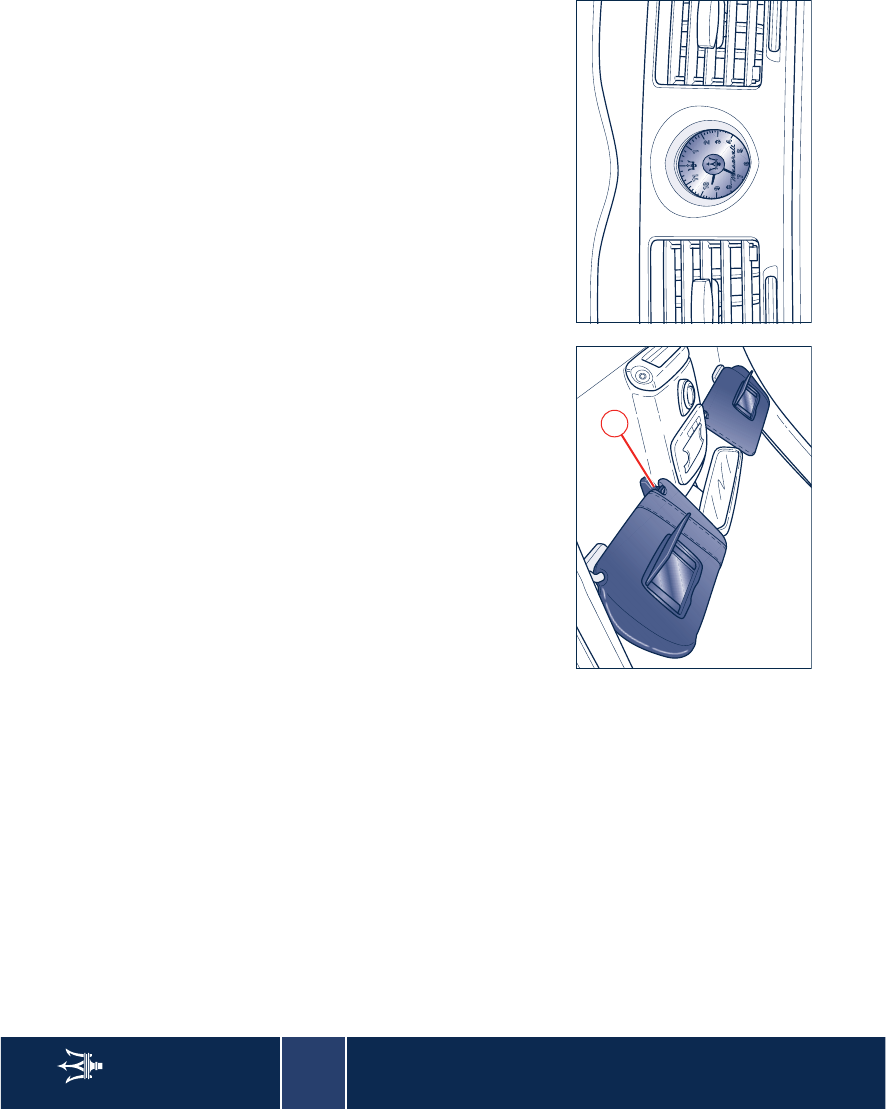
3
82 Internal outfits
Deleting the programmed keys
Unlike programming which is done for
each individual key, deletion is done
for all three keys simultaneously.
To delete proceed as follows:
– press and hold down the keys H and
J;
– after about 20 seconds, the LED K
starts flashing;
– release the keys.
WARNING: It is advisable to carry out
the Home Link deletion procedure
when selling the vehicle.
Sun visors
They can be folded to the front and to
the side of the vehicle. To move the
visor to the sides, lower and release it
from the catch L.
By lowering the visor on the
passenger's side you can access the
courtesy mirror with incorporated
light; the latter switches on
automatically (with the ignition key in
the MAR position) raising the mirror
protective cover. Before raising the
visor, close the mirror cover.
Clock
The clock is adjusted automatically by
setting the time with the Multi Media
System.
The clock lights up when the external
lights are turned on.
L
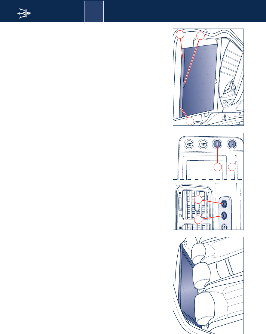
3
Internal outfits 83
Rear window sunshade
The electrical sun shade works with the
ignition key in the MAR position.
The switch buttons are located both on
the front and on the rear dashboard.
WARNING: Before activating the
sunshade, make sure that there are no
objects that may interfere with its
travel.
Press button M to raise the sunshade
and button N to lower it.
WARNING: If the sunshade guide
needs to be cleaned with solvents, it
must then be greased in the area
where the sunshade slides using Teflon
based grease.
WARNING: If, within a time period of
25 seconds, the sunshades are raised
and lowered at least 4 times, the
relative control will disable them for 30
seconds. Before disabling the
sunshade, the system will complete the
movement in progress. The last
movement accepted will be opposite
to the starting movement.
Rear door sunshades
Housed on the rear doors, they wind
up automatically. To pull out the
sunshade, pull on the grip O and latch
it into the catches P located on the top
edge of the door.
M N
M
N
P
P
O
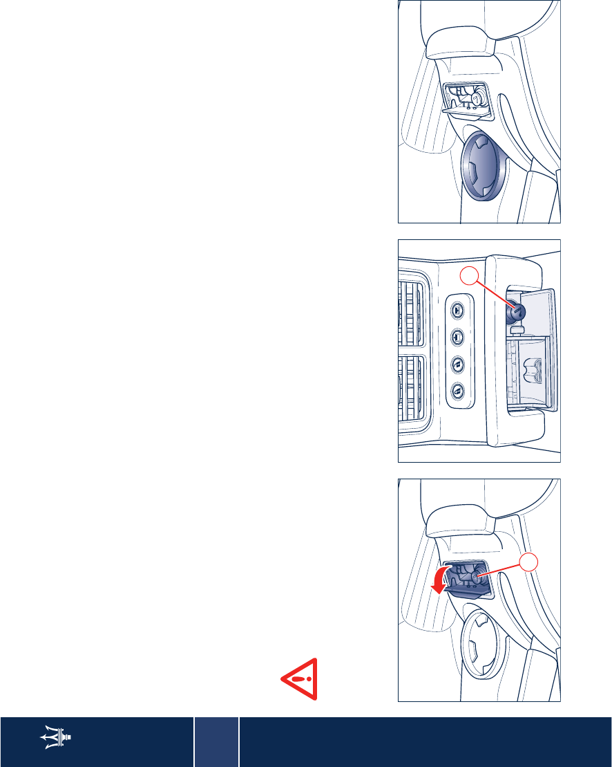
3
84 Internal outfits
Front ashtray and cigarette
lighter
They are found on the central console,
hidden by a cover. Press the rear part to
open the cover.
Pressing button Q operates the
cigarette lighter. After about 20
seconds this returns automatically to
the initial position and is ready for use.
Remove the tray in order to clean the
ashtray.
WARNING: Always make sure that the
cigarette lighter has been switched off.
The cigarette lighter reaches
high temperatures. Handle it
carefully and do not allow
children to use it: risk of fire and
burns!
Rear ashtray
It is located on the rear central console,
hidden by a cover. To open the cover,
hold and pull it from the protruding
part.
Pressing button R fully down operates
the cigarette lighter. After about 20
seconds this returns automatically to
the initial position and is ready for use.
Remove the tray in order to clean the
ashtray.
Glass compartment
This is positioned on the tunnel, near
the handbrake lever, and it can contain
either a glass or a can.
Q
R
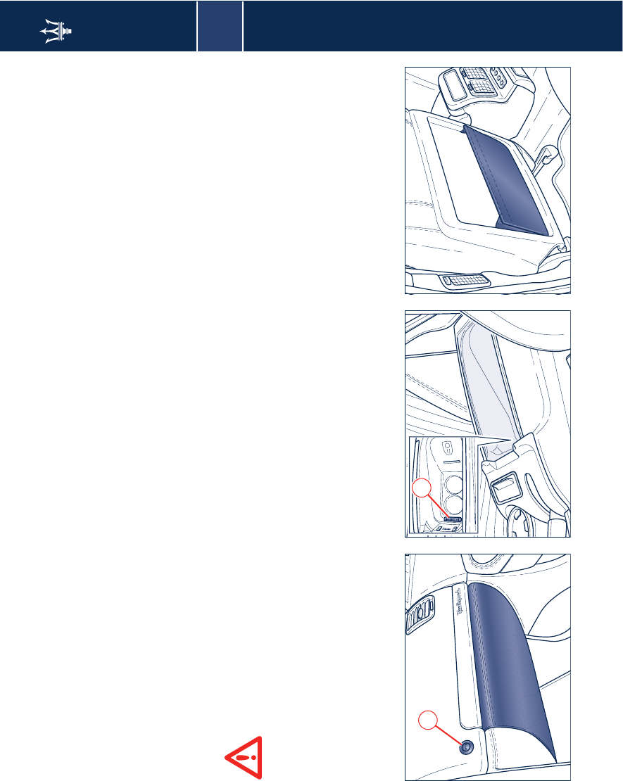
3
Internal outfits 85
Glove compartment
Positioned in the lower part of the
dashboard, on the passenger side, it
can be opened pressing button S. The
latter only works with the ignition key
turned to MAR and for about 10
minutes after having extracted the key
or rotated it to the STOP position.
The compartment is lit by a courtesy
light when it is open.
To ensure passenger safety,
the compartment must always
remain closed while driving.
If the button controlled opening is
faulty, the compartment can be
opened by pulling the emergency
cable behind the compartment itself.
WARNING: It is unadvisable to place
particularly heavy objects in the glove
compartment.
Beverage cooler
The front armrest houses a lit beverage
holder into which air is conveyed
directly from the air conditioning
system.
To access the compartment, pull the
armrest holding it from the handgrip.
To activate the air-conditioning/
ventilation inside the compartment,
move control T upwards. To stop it,
lower back the control.
WARNING: The temperature of the air
inside the beverage cooler is the same
that as that coming out from the air
conditioning/heating vents, it
therefore depends on the temperature
set via the relative control panel.
Map pockets
The front seats are fitted with map
pockets located on the rear of the
seatbacks.
WARNING: Do not put heavy or sharp
objects in the map pockets.
ST
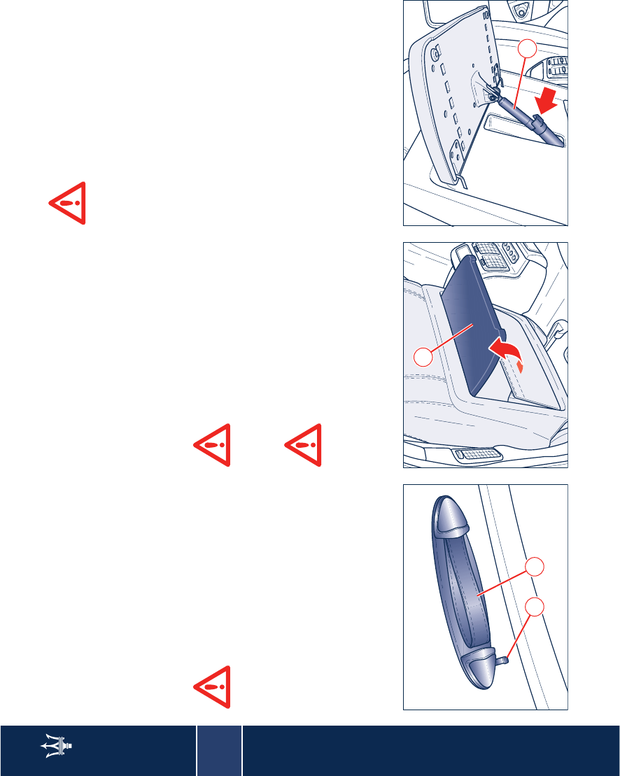
3
86 Internal outfits
Handholds
Usually laying in a horizontal position,
the handhold U can rotate until
reaching a vertical position. A return
spring automatically repositions the
handhold in the horizontal position.
The rear handholds also include a
clothing hook, V.
Turn the hooks to the clothes
position when not used.
Tables (optional)
They are installed on the back of the
front seats.
Opening: lift the table W until the
supporting mechanism clicks in place.
Closing: press the support bracket X to
release the mechanism and then lower
the table W.
When one or more tables are
open, passengers traveling in
the rear seats must fasten
their seat belts as indicated on the
table.
When travelling with one or
more child seats fitted on the
rear seat of the vehicle, the
tables must be in closed position.
When closing the table always
guide it down: risk of
crushing!
WARNING: As the table is not
equipped with holding devices, do not
place open containers of drinks on the
tables during the journey as the
surrounding upholstery could be
stained or damaged if they fall over.
UV
W
X