Marine Data Systems MIV30 Shipboum Automatic Identification System (AIS) User Manual MIV installation manual rev11g
Marine Data Systems Shipboum Automatic Identification System (AIS) MIV installation manual rev11g
Installation Manual

AIMS MIV
AIS 1371-1 Technology
TECHNICAL USER MANUAL
Revision 01

IMPORTANT WARNINGS
DANGER: HIGH VOLTAGE!
RISK OF ELECTRICAL SHOCK!
This unit has a high voltage source inside.
Disconnect from the power before opening.
DO NOT remove the covers while the unit is switched on.
5 Volt electrical power on GPS and DBR (when fitted) antenna ports.
NOTICE
Compass safe distance is 1 meter.
NOTICE
No user serviceable parts inside, servicing only by properly
qualified and certified technical staff.
NOTICE
The GPS module uses a back-up battery to ensure quick start-up
of the GPS unit. This battery must be replaced every 5 years.
NOTICE
This manual is for informational use only, and may be changed without notice. This manual
should not be construed as a commitment of Marine Data Systems. Under no
circumstances does Marine Data Systems assume any responsibility or liability for any
errors or inaccuracies that may appear in this document. The equipment should only be
used for the purposes intended by the manufacturer; any deviation from this will void the
warranty of the product.
Document No. 1101-0010-AA-00-TM
Issue: 10
Marine Data Systems (Pty.) Ltd.
AIMS MIV Manual Table of Contents
AIS 3
TABLE OF CONTENTS
1. INTRODUCTION.............................................................................................. 7
1.1. Automatic Identification System (AIS) Overview .........................................7
1.2. AIS Unit Overview......................................................................................7
1.2.1. Data Interfaces..............................................................................................................7
1.2.2. RF Interfaces.................................................................................................................8
1.2.3. Technical data...............................................................................................................8
1.2.4. Dimensions And Weights..............................................................................................8
1.2.5. Receiver Default Frequencies.......................................................................................9
1.2.6. AIS Receivers ...............................................................................................................9
1.2.7. AIS Transmitter .............................................................................................................9
1.2.8. DSC Receiver................................................................................................................9
1.2.9. Alarm Relay.................................................................................................................10
1.2.10. Compass Safe Distance..............................................................................................10
1.2.11. Navigation Specifications (Internal Sensors) ..............................................................10
1.2.12. Listener and Talker Specifications ..............................................................................11
2. INSTALLATION ............................................................................................. 13
2.1. Unpacking the Unit....................................................................................13
2.2. Mounting the Unit......................................................................................13
2.3. External Interfaces....................................................................................15
2.4. Grounding the AIS unit..............................................................................16
2.5. AIS VHF Antenna installation....................................................................17
2.5.1 Alternative VHF antenna installation options...................................................................18
2.5.1.1. Option 1 ..............................................................................................................................18
2.5.1.2. Option 2 ..............................................................................................................................19
2.5.2. Minimising Interference: Additional Guidelines ...........................................................19
2.6. AIS GPS Antenna Installation ...................................................................19
2.7. Cable and Plug Connection Specifications................................................20
2.7.1. RF Cables ...................................................................................................................20
2.7.1.1. GPS Antenna (Cable type E)...............................................................................................20
2.7.1.2. VHF Antenna (Cable type F) ...............................................................................................21
2.7.1.3. DBR Antenna (Cable Type L).............................................................................................. 21
2.7.2. Data Interface Connections.........................................................................................21
2.7.2.1. Presentation Interface ......................................................................................................... 21
2.7.2.2. Pilot Port .............................................................................................................................23
2.7.2.3. KDU (Keyboard Display Unit) .............................................................................................. 23
2.7.2.4. Long-Range Communication Port (L/RANGE I/O)...............................................................24
2.7.2.5. Sensor Input Ports (SENS 1, SENS 2, SENS 3) .................................................................24
2.7.2.6. DGNSS Port........................................................................................................................ 25
2.7.2.7. Service Port......................................................................................................................... 26
2.7.3. Power Supply Input .....................................................................................................27
2.7.4. Alarm Relay Connection .............................................................................................27
2.7.5. Cable Assemblies .......................................................................................................28
2.7.5.1. Cable Types A, B, C, D ...................................................................................................... 28
2.7.5.2. Cable Type G Assembly – Power cable ..............................................................................29

Table of Contents AIMS MIV Manual
4AIS
2.7.5.3. Cable Type H Assembly – Alarm cable ...............................................................................29
2.7.5.4. Cable Type J Assembly....................................................................................................... 30
2.7.5.5. Cable Type E, F and L Assembly ........................................................................................31
2.8. Installation Check......................................................................................32
3. TECHNICAL DESCRIPTION.......................................................................... 33
3.1. AIS unit Overview .....................................................................................33
3.2. System Modes of Operation......................................................................34
3.2.1. Mobile Station .............................................................................................................34
3.3. Serial Communications .............................................................................34
3.3.1. Presentation, Pilot and KDU ports ..............................................................................34
3.3.2. Sensor ports (input sentences only)............................................................................38
3.3.2.1. Position and Time: ..............................................................................................................38
3.3.2.2. Speed over ground:............................................................................................................. 39
3.3.2.3. Course over ground:............................................................................................................ 40
3.3.2.4. Heading:.............................................................................................................................. 40
3.3.2.5. RAIM indicator:....................................................................................................................40
3.3.2.6. Rate of turn: ........................................................................................................................40
3.3.3. Service port.................................................................................................................41
3.3.4. Long Range port .........................................................................................................41
3.4. Alarm messages.......................................................................................41
3.5. Status messages ......................................................................................44
3.6. AIS Receiver Module (RCM 1 or 2)...........................................................44
3.7. Usage of NMEA sentences.......................................................................44
4. SERVICE........................................................................................................ 49
4.1. Explanation of the LEDs............................................................................49
4.2. System Indicators (additional information) ................................................50
4.2.1. DIFF. FIX.....................................................................................................................50
4.2.2. Receiver failure ...........................................................................................................50
4.3. Alarm relay................................................................................................50
4.4. Troubleshooting ........................................................................................50
4.5. Security log retreival .................................................................................50
4.6. Replacing the Modules..............................................................................52
5. APPENDICES ................................................................................................ 54
5.1. Abbreviations ............................................................................................54
5.2. Reference Documents ..............................................................................56
5.2.1. List of standards and specifications: ...........................................................................56
5.2.2. List of Related Software and Manuals:........................................................................57
5.3. AIMS Serial interface “Listener” and “Talker” circuit diagrams ..................58
LIST OF FIGURES
Figure 1: AIS Unit Dimensions..................................................................................... 14
AIMS MIV Manual Table of Contents
AIS 5
Figure 2: Mounting the AIS Unit................................................................................... 14
Figure 3: External Interface Block Diagram ................................................................. 15
Figure 4: External Interfaces on the rear panel of the AIS unit..................................... 15
Figure 5: Grounding the AIS unit ................................................................................. 17
Figure 6: AIS Antenna and Ship’s VHF Placement ...................................................... 18
Figure 7: Alternative AIS Antenna and Ship’s VHF Placement..................................... 19
Figure 8: Data Cable Terminations (AIS unit Side) ...................................................... 28
Figure 9: Cable Type G Assembly (AIS unit Side) ....................................................... 29
Figure 10: Cable Type H Assembly (AIS unit Side)...................................................... 29
Figure 11: Cable Type J Assembly .............................................................................. 30
Figure 12: Cable type E, F and L Assembly................................................................. 31
Figure 13: AIS unit Block Schematic............................................................................ 33
Figure 14: Ship dimensions and related fields ............................................................. 38
Figure 15: AIS unit Module Layout (bottom view)......................................................... 52
Figure 16: AIS unit Module Layout (top view)............................................................... 52
Figure 17. RS422 General “Listener” circuit diagram................................................... 58
Figure 18. RS422 General “Talker” circuit diagram...................................................... 58
LIST OF TABLES
Table 1: Presentation Interface Messages................................................................... 36
Table 2: Vessel and Cargo type................................................................................... 37
Table 3: Position Sensor Precedence.......................................................................... 39
Table 4: Rate of Turn Sensor Precedence................................................................... 40
Table 5: AIS Standard alarm messages ...................................................................... 42
Table 6: Proprietary alarm definitions .......................................................................... 43
Table 7: Proprietary status messages.......................................................................... 44
Table 8 : NMEA message usage .................................................................................. 48
Table 9: LED Operation................................................................................................ 49

Table of Contents AIMS MIV Manual
6AIS
Marine Data Systems would like to take this opportunity to congratulate you on
the purchase of your AIS unit. We want to assure you that this product is manufactured
from only the highest quality components and thoroughly tested to ensure your complete
satisfaction.
If you have any questions, or queries related to this product, please do not hesitate to
contact us:
Physical Address:
580 Kyalami Boulevard
Kyalami Business Park
Kyalami
Midrand
South Africa
Postal Address:
PostNet Suite #4
Private Bag X11
Halfway House
1685
South Africa
Email: support@marinedata.co.za
Website:
www.marinedata.co.za
Telephone:
+27 11 549 1800
Fax: +27 11 549 1867
Thanking you,
THE MDS TEAM
AIMS MIV Manual Introduction
AIS 7
1. INTRODUCTION
1.1. Automatic Identification System (AIS) Overview
AIS is a radio data system where two or more stations operate on one or more radio
channels using Time Division Multiple Access (TDMA). These units can be mobile, base or
repeater stations. Mobile stations are installed onboard vessels and integrated to the
vessel’s sensors and display systems. Base stations, on the other hand, are installed on the
shore side and allow remote monitoring of vessel traffic within the VHF coverage area of the
base station. Base stations can be interconnected via an AIS Network to cover a larger
area. Repeater stations can be used to extend the required coverage area, preferably
where the traffic load is low and there is a lack of suitable communications infrastructure.
The main objective of the system is to assist in safer navigation; that is, sharing ship-to-ship,
positional information, speed over ground, course over ground, heading, rate of turn, static
and voyage information, as well as safety-related messages.
The Automatic Identification System (AIS Class A) is defined by the IMO and has been
made a carriage requirement by the latest revision of SOLAS Chapter V. This does not only
require the AIS to be installed, but also to provide information used for ship navigation.
The AIS has been standardised by the ITU and IEC and is subject to type approval. In order
to fulfil the reliability requirements of information exchange, care must be taken to ensure
the AIS unit is correctly installed.
1.2. AIS Unit Overview
The AIS Unit operates in the VHF Maritime Mobile Band and, according to its programmed
mode, operates:
• Ship to ship,
• Ship to shore,
• Shore to ship.
The AIS Unit operates autonomously with minimum user intervention and has a built-in
display that monitors system health and activity. It is made up of a set of easily removable
modules that can be replaced without any system adjustment or calibration.
It also incorporates those features of Digital Selective Calling (DSC) required by the AIS
specifications. This means that the AIS Unit transmits and receives specified AIS related
DSC messages on the maritime VHF DSC channel 70.
1.2.1. Data Interfaces
The AIS Unit is equipped with external interfaces that allow connection to:
• Keyboard Display Unit (KDU)
• Pilot’s Display Unit (PDU)
• 3 Ship’s Sensors Inputs (Typically Gyro, GPS and ROT Sensor)
• Ship’s ARPA Radar
Introduction AIMS MIV Manual
8AIS
• Ship’s ECDIS/ECS
• Other NMEA-compliant ship’s navigation equipment
Displaying of incoming messages requires the connection of an external terminal to at least
one of the specified interfaces, such as a Keyboard Display Unit.
1.2.2. RF Interfaces
The AIS Unit has three RF interfaces:
• VHF Antenna
• GPS Antenna
• Differential Beacon Receiver Antenna (DBR port) for optional internal DBR
1.2.3. Technical data
Classification Class A shipborne equipment of the Universal Automatic Identification
system (AIS). Complies with recommendation ITU.R M.1371-1, IEC 61993-
2, IEC 61162-2, IEC 60945 and IMO resolution MSC.74 (69) Annex 3.
AIS Unit Presentation Interface According to Specification IEC 61993-2, IEC 61162-1, IEC 61162-2*.
RS422 interface 2 pair cable (shielded) up to 100m carrying TX/RX data
Or
RS232 interface Multi-conductor cable (shielded) up to 15m carrying TX/RX data.
Services
• GPS Position reporting
• Short message services.
• BIT display.
• AIS related DSC
AIS Modulation TX/RX 9.6kbits/s GMSK
AIS Coding HDLC with bit stuffing
Supply Voltage 24VDC (+30% to -10%)
Supply Switched mode with Galvanic Isolation
Power consumption Maximum 4A at 24VDC in transmit; Nominal 2A at 24V
Operating Temperature range -15 to +55°C.
Heat Dissipation 100W (during transmit)
Power Fuse 6.3A
* The AIS unit is compliant with IEC 61162-1 and available in IEC 61162-2 on the physical level at customer request for early
versions of this product. Later versions of the product are IEC 61162-2 compliant by default.
NOTE: The input power to the AIS unit has reverse and over-voltage protection. If the polarity of the input power is
incorrect, the unit will not switch on. Correct the polarity to restore operation. If the voltage to the AIS unit
goes over 32V to 35V, the unit will protect it by blowing the fuse on the rear panel of the unit. Correct the
voltage and replace the fuse to restore operation.
1.2.4. Dimensions And Weights
Width 445mm
Height 80mm
Depth 360mm
Weight 8.5kg
AIMS MIV Manual Introduction
AIS 9
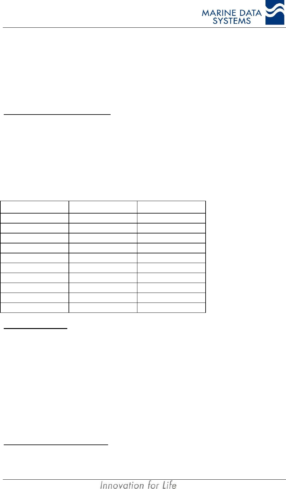
1.2.5. Receiver Default Frequencies
Designation Channel Frequency (MHz)
AIS1 87B 161.975
AIS2 88B 162.025
DSC 70 156.525
1.2.6. AIS Receivers
Frequency range 156.025MHz to 162.025MHz
Channel spacing 12.5kHz and 25kHz
AIS Modulation 25kHz Channels: GMSK
AIS Modulation 12.5kHz Channels: GMSK
AIS Data Rate 9,600bits/s
10% or better at -107dBm (25kHz)
Packet Error Rate (PER) 20% or better at -98dBm (12.5kHz)
70dB (25kHz)
Adjacent Channel Rejection 50dB (12.5kHz)
Blocking and Intermodulation PER 20% for 1 tone -15dBm at Fo ±5.725MHz and
2 tones of -27dBm at Fo +500kHz and Fo +1MHz.
Large Signal PER (-7dBm) 1% or better
Image Rejection ≥ 70dB for 20% PER
IF Rejection ≥ 70dB for 20% PER
Spurious Rejection ≥ 70dB for 20% PER
Frequency Stability ±1ppm
1.2.7. AIS Transmitter
Frequency Range 156.025MHz to 162.025MHz
Output Power 12.5W or 2W
Harmonic Emission ≤ -77dBc (≤ 0.25µW)
Spurious Emission ≤ -77dBc (≤ 0.25µW)
Ramp Up ≤ 1ms
Ramp Down ≤ 1ms
Antenna Output Impedance 50Ω
Channel Protection 1 second max on air
Frequency Accuracy ±0.5kHz (Normal temperature conditions 15°C to 35°C)
±1kHz (Extreme temperature conditions –15°C to15°C and 35°C to 55°C)
1.2.8. DSC Receiver
Frequency Range Always fixed to Channel 70
Channel Spacing 25kHz
Modulation 1300Hz/2100Hz 2 Tone FSK
Data Rate 1,200bits/s
BER ≤ 10-4 at –107dBm
Introduction AIMS MIV Manual
10 AIS
Adjacent Channel Rejection 70dB (25kHz)
Blocking ≥ 84dB
Image Rejection ≥ 70dB
IF Rejection ≥ 70dB
Frequency Stability ±1ppm
NOTE: When required, the AIS Unit may be equipped with a 4th receiver. This can be used where it is required to
receive additional data such as radar footprint broadcasts from a shore station without interfering with
normal AIS operation. It is also possible to replace the DSC receiver with another AIS receiver when DSC
is not required. Contact your distributor for more details.
1.2.9. Alarm Relay
The AIS unit has an alarm relay built-in as a standard feature. It is accessible using the
alarm interface connector, located on the rear panel.
Contact rating
Voltage (Average) 24VDC
Current (Maximum) 1A
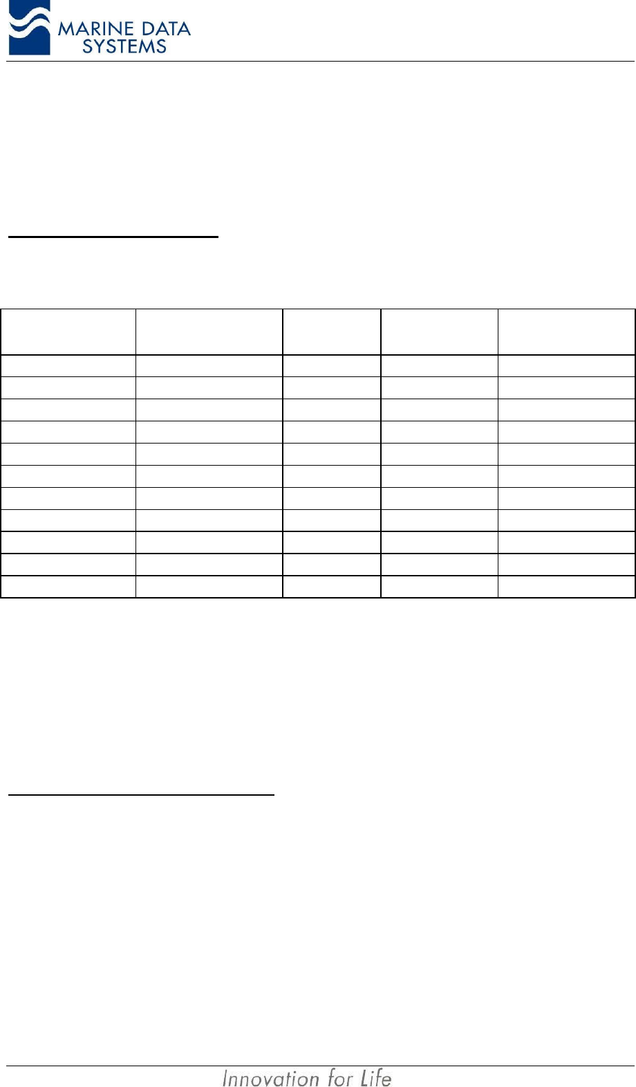
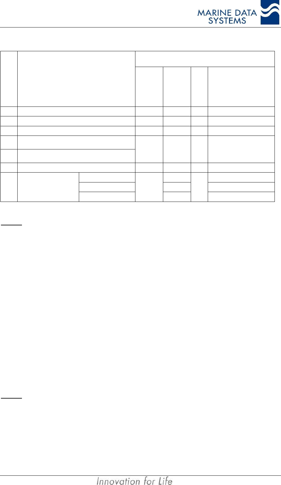
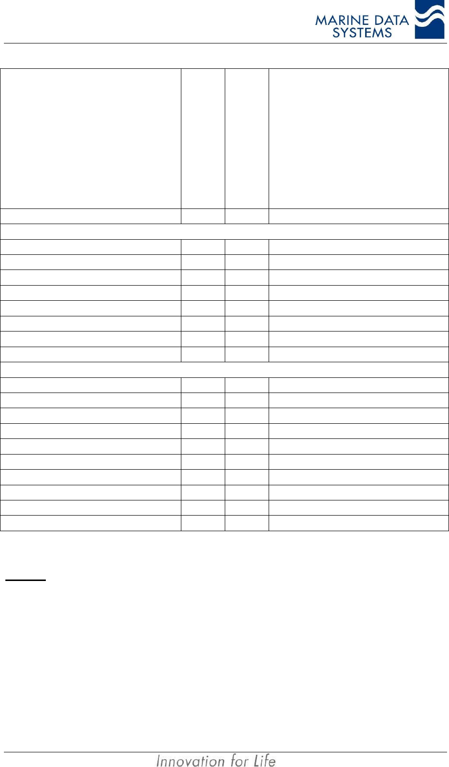
1.2.10. Compass Safe Distance
Compass Safe measurements, in accordance with IEC 60945, are given below in metres:
Distance from Compass
(m) Compass Reading (Degrees) Compass Deviation (Reading-Background)
(Degrees)
Background (No EUT
Present) 270.00 -
0.1 276.7 6.7
0.2 271.1 1.1
0.3 270.2 0.2
0.4 270.0 0.0
0.5 270.0 0.0
0.6 270.0 0.0
It is recommended to mount the AIS unit more than 1m from the compass to prevent any
interference.
1.2.11. Navigation Specifications (Internal Sensors)
8/12 Channel Internal Global Positioning System (GPS) [Standard].
Internal Differential Beacon Receiver (DBR) [Optional].
NOTE:The ship’s GPS/DGPS NMEA sensor will normally be connected to any of the three sensor input ports
(Sensor 1, Sensor 2 or Sensor 3). The internal GPS is always present but is only used for acquiring
position data when it is differentially corrected and an external differentially corrected GPS is not available.
Refer to Table 3: Position Sensor Precedence, on page 39, for a full position sensor precedence listing.
AIMS MIV Manual Introduction
AIS 11
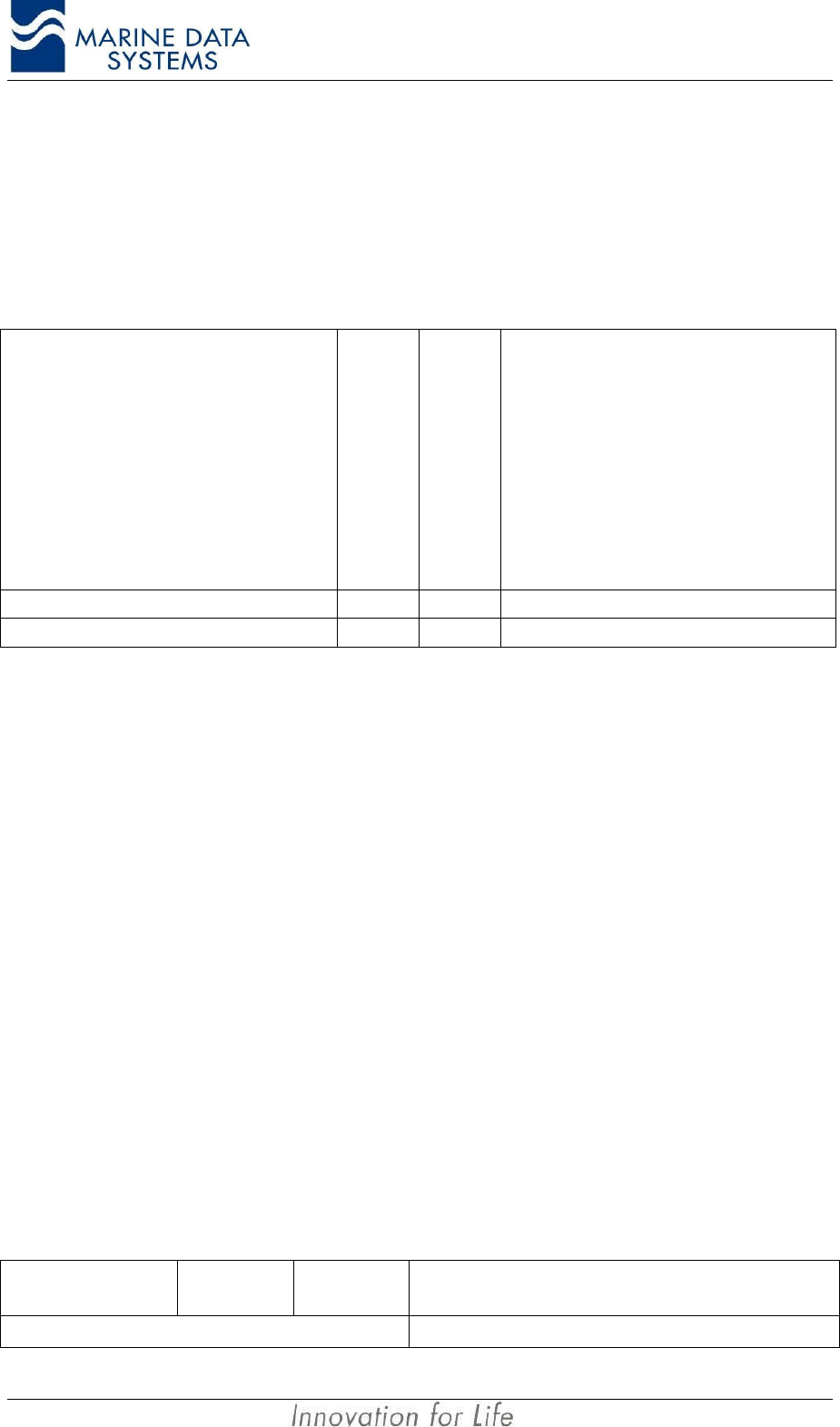
1.2.12. Listener and Talker Specifications
Listener load
Vin = +10V, other input = GND 1.8mA (typical)
Vin = -10V, other input = GND -2.7mA (typical)
Differential input voltage sensitivity 200mV (typical)
Talker drive capability
Current drawn Differential Output Voltage
25mA (typical) 3V differential output
48mA (typical) 2V differential output
58mA (typical) 1.5V differential output

AIMS MIV Manual Installation
AIS 13
2. INSTALLATION
Since the installation of an AIS unit is complex, an initial installation configuration report,
made during installation, should be kept on board the vessel. This should include at least
the following:
• AIS configuration data (i.e. MMSI, ship name, etc.)
• Antenna layout
• AIS arrangement drawing
• Interconnection diagram
2.1. Unpacking the Unit
The AIS Unit package includes the following:
• AIS Unit
• Power connector
• Mounting bracket set with mounting screws
• 2 x Spare fuses
• This technical manual
• Alarm output connector
• Declaration of Conformance
• Factory test result sheet
• CD with AIMS utility and manual (Optional)
2.2. Mounting the Unit
The AIS Unit should be mounted to a bulkhead, either on the bridge, in the chart room or the
radio room. It may also be mounted to any suitable flat surface, where the unit will not be
exposed to the elements and with access to all the relevant sensors and interfaces. AIS
equipment is categorised as “Protected Equipment” under IEC 60945 (an environmental
standard for equipment).
To prevent the build-up of heat, the AIS Unit should be mounted in a space with good
ventilation.
Care must be taken when mounting the AIS Unit to ensure that there is sufficient space for
the cables and connectors. In particular, sharp bending of the RF cables must be avoided.
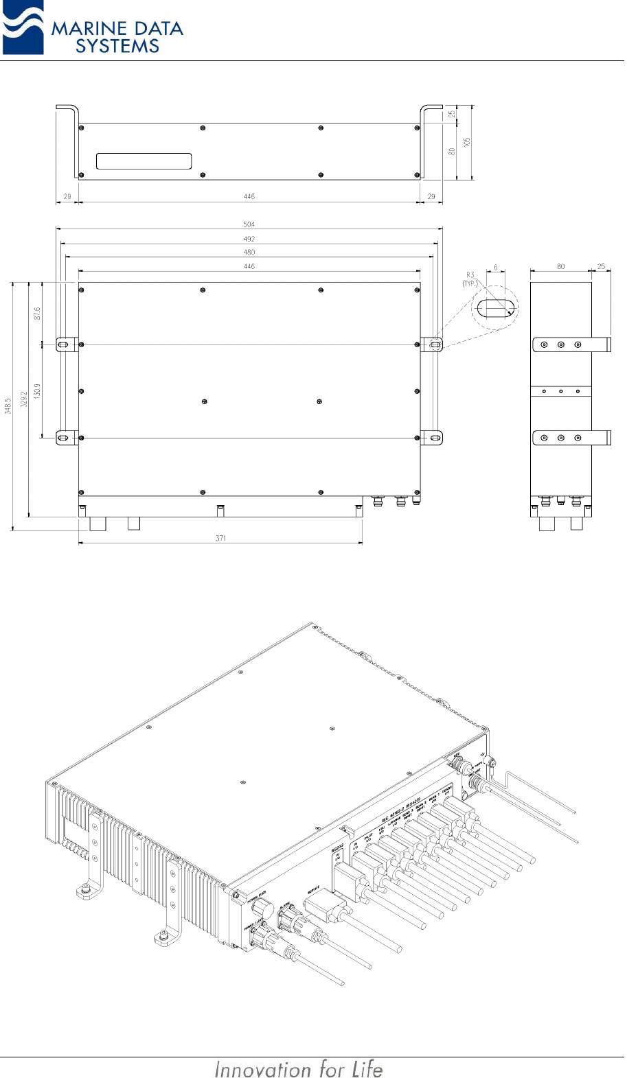
• Attach the bracket assemblies to the unit, using the screws supplied, see Figure
2: Mounting the AIS Unit.
• Mount the unit to a suitable surface (as explained above), using the mounting
brackets and some mounting screws.
• Ensure that the unit is mounted so that the display can easily be read for
diagnostic and maintenance purposes.
Installation AIMS MIV Manual
14 AIS
Figure 1: AIS Unit Dimensions
Figure 2: Mounting the AIS Unit
AIMS MIV Manual Installation
AIS 15
2.3. External Interfaces
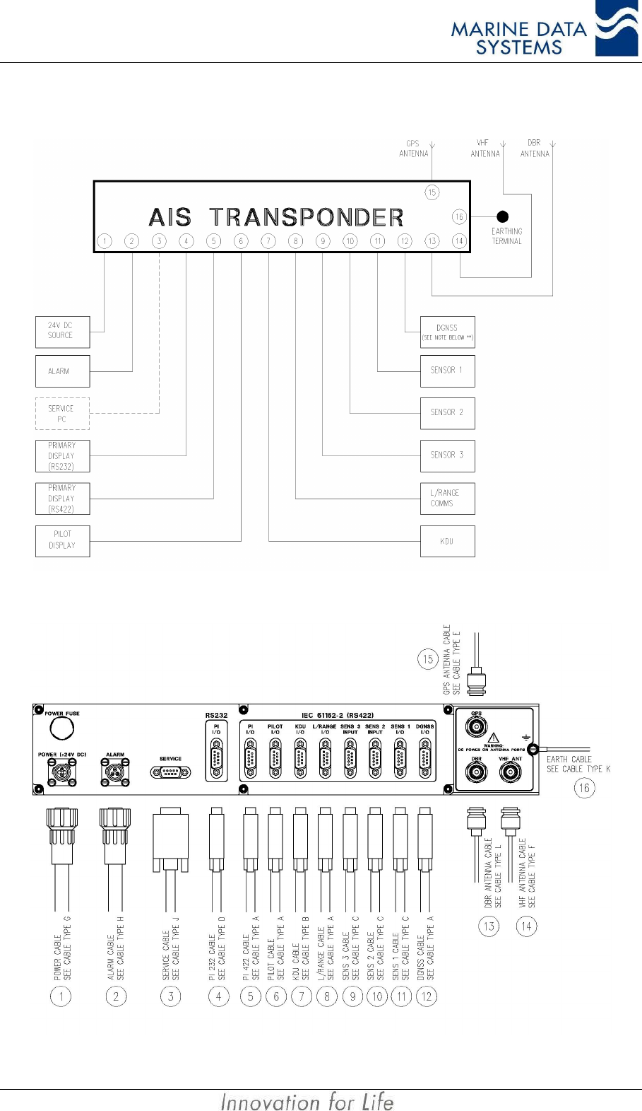
Figure 3: External Interface Block Diagram
Figure 4: External Interfaces on the rear panel of the AIS unit
Installation AIMS MIV Manual
16 AIS
External Interface Legend (refers to Figure 3 and Figure 4)
Interface
Reference Designation Details
1Power +24VDC Input. Connector Type G
2Alarm Alarm Relay Output. Connector Type H
3Service Port For download of software upgrades. Cable Type J. Only used by
service personnel.
4,5 Presentation Port (Primary
Display) Primary Display port. Cable Type D or A (*)
6Pilot Port Pilot’s Display Port. Cable Type A.
7KDU Keyboard Display Unit. Cable Type B.
8Long Range Port For Log Range Communications Terminal. Cable Type A.
9Sensor 3 For Navigation Sensor Input. Cable Type C.
10 Sensor 2 For Navigation Sensor Input. Cable Type C.
11 Sensor 1 For Navigation Sensor Input. Cable Type C.
12 DGNSS
Output of GPS Differential Correction Data (when Beacon Receiver
fitted as option or differential data is received on VDL). Input of
externally derived Differential Correction Data. Cable Type A.
Otherwise unused) (**).
13 DBR Antenna TNC DBR Antenna Port. Cable type L.
14 VHF Antenna TNC VHF Antenna Port. Cable Type F.
15 GPS Antenna TNC GPS Antenna Port. Cable Type E.
16 Earth Chassis Earthing Terminal. Cable Type K.
For cable type definitions, refer to section 2.7
NOTES: *The RS232 port may not be used on ship installations, because it will cause currents to flow
through the ship’s hull and cause corrosion. RS232 ports also causes unwanted electromagnetic
emissions.
** This is a non-mandatory port to provide for situations where an external differential data source
is available and GPS Differential correction data can be fed to the GPS in the AIS unit. Also,
when the AIS unit is fitted with the optional internal Differential Beacon Receiver, the Differential
Correction Data from that Beacon Receiver will be output from this port for application to an
external GPS. This port may only be used with the correct software options. Consult your
supplier.
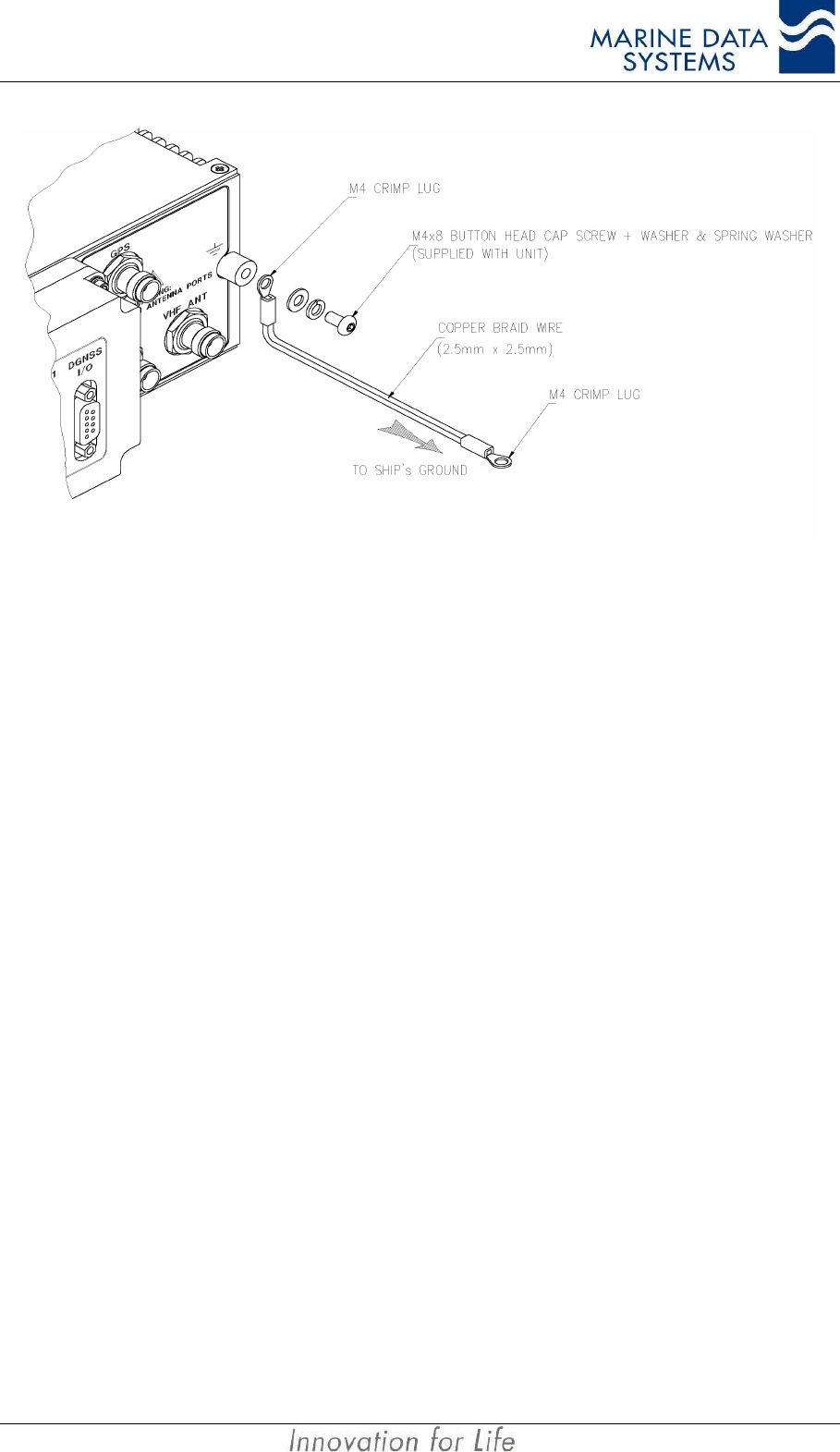
2.4. Grounding the AIS unit
Using a crimp lug and 2.5mm x 2.5mm copper earth strap, the AIS unit should be connected
to the ship’s ground directly with an earth strap as shown below. The earth strap should not
be more than 1m. If a longer earth strap is required, thicker wire should be used.
The copper earth strap and the steel bulkhead connection should be brazed soldered (i.e.
hard solder), for vibration and anti-corrosion purposes. Protective paint can be applied over
the earth lug to prevent any degradation in connectivity due to salt corrosion.
AIMS MIV Manual Installation
AIS 17
Figure 5: Grounding the AIS unit
2.5. AIS VHF Antenna installation
The AIS unit is a low-noise device, but as it transmits short bursts of energy on a continuous
basis, the possibility of interference with other VHF radios must be minimised by following
the guidelines provided below. The interference will be heard as a periodic soft clicking
noise on the VHF radiotelephone. This effect may become more noticeable when the
radiotelephone is operating on channels near the AIS operating channels.
Location of the mandatory AIS VHF antenna should have first priority, since digital
communications are more sensitive than analogue voice radios to interference created by
reflections from obstructions such as masts and booms. To minimise interference, the
following guidelines should apply:
• The AIS VHF antenna should have omni-directional vertical polarisation.
• The AIS VHF antenna should be placed in an elevated position that is as free as
possible from constructions made of conductive materials, with a minimum of 2
metres in horizontal direction. The antenna should not be installed close to any
large vertical obstruction. The objective is for the AIS VHF antenna to see the
horizon freely through 360 degrees.
• The AIS VHF antenna should be installed safely away from interfering high-
power energy sources such as radar and other transmitting radio antennas -
preferably at least 3 meters away from, and outside of the transmitting beam.
• There should not be more than one antenna on the same level. The AIS VHF
antenna should be mounted directly above or below the ship’s primary VHF
radiotelephone antenna, with no horizontal separation and with a minimum of 5
metres vertical separation. If it is located on the same level as other antennas,
the distance apart should be at least 10 metres.
Installation AIMS MIV Manual
18 AIS
2.5.1 Alternative VHF antenna installation options
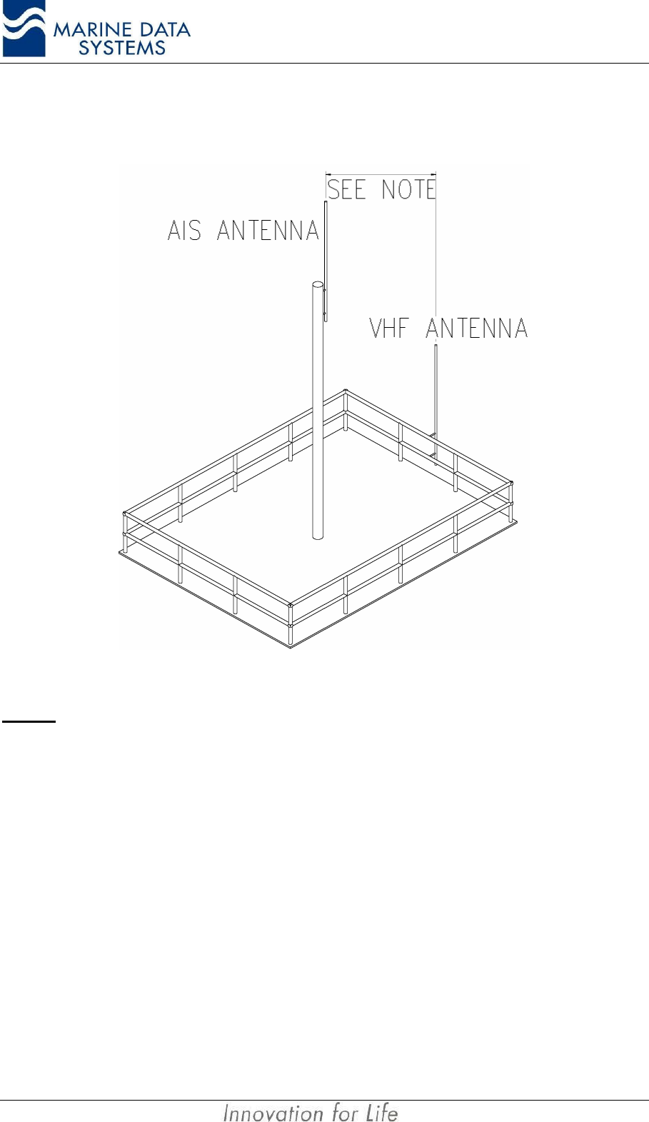
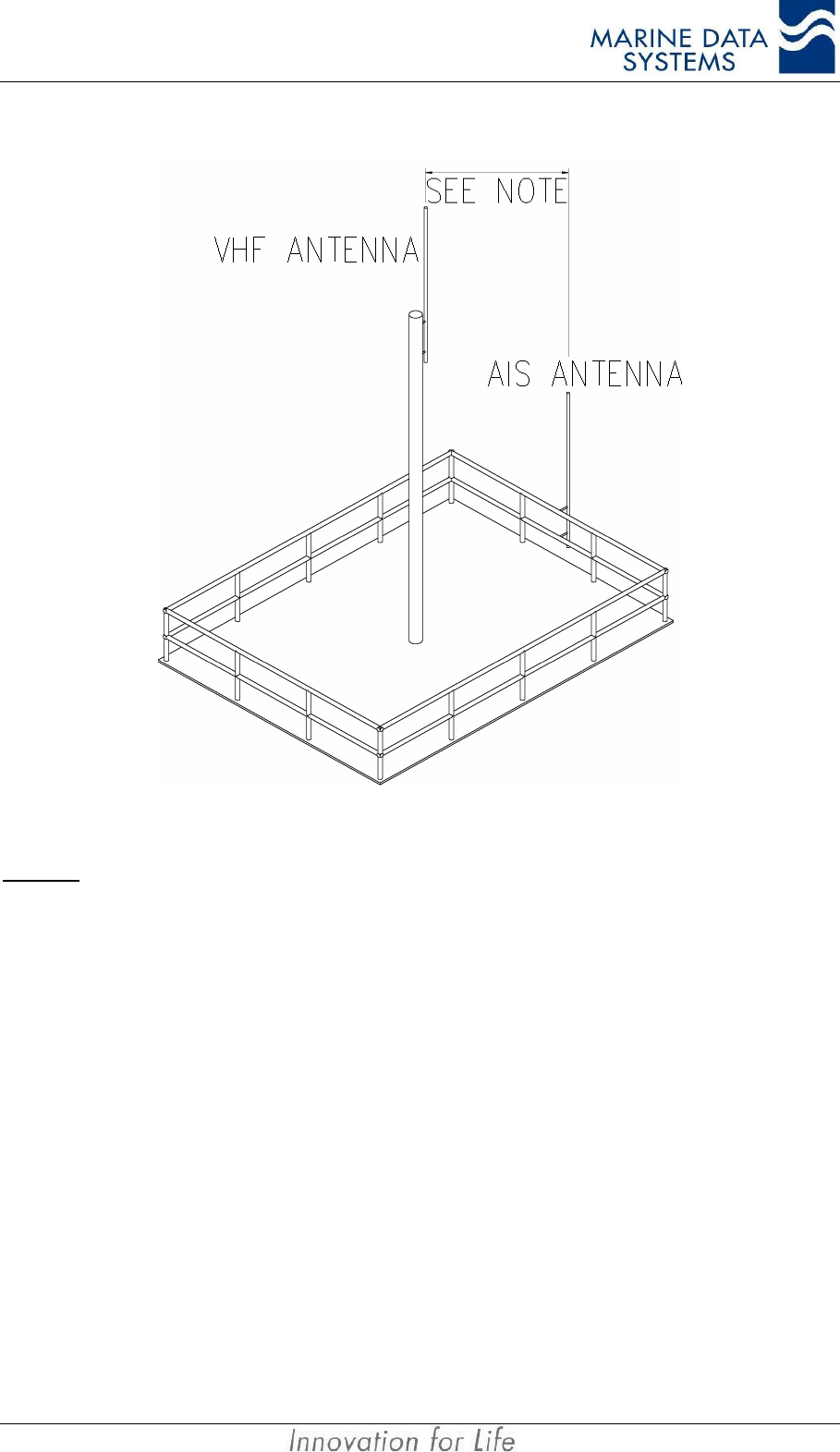
2.5.1.1. Option 1
Figure 6: AIS Antenna and Ship’s VHF Placement
NOTES:• This arrangement should only be used when it is not possible to mount the antenna on a mast with
suitable vertical antenna separation. Maximum separation of the antennas is essential.
• When this arrangement is used, great care must be taken to ensure that minimum interference is
caused to other VHF equipment.
AIMS MIV Manual Installation
AIS 19
2.5.1.2. Option 2
Figure 7: Alternative AIS Antenna and Ship’s VHF Placement
NOTES: • This arrangement should only be used when it is not possible to mount the AIS antenna on the
highest possible position with suitable vertical antenna separation. Maximum separation of the
antennas is essential.
• When this arrangement is used, great care must be taken to ensure that minimum interference is
caused to other VHF equipment.
2.5.2. Minimising Interference: Additional Guidelines
When mounting the AIS antenna away from a mast that carries ship’s VHF Antennas,
always keep the AIS antenna as far away from the other VHF Antennas as possible
After installing and commissioning the AIS unit, remember to listen to the ship’s VHF radios
while the AIS unit is operating. In the unlikely event of interference, you will have to make
changes to the antenna installation.
2.6. AIS GPS Antenna Installation
The AIS GPS antenna installation position is critical to the working of the AIS system. The
AIS GPS antenna must be installed so that it has a clear view of the sky. The antenna must
see the horizon through 360 degrees, horizontally, and 5 to 90 degrees, vertically, above the
horizon. Small diameter obstructions, such as masts and booms, will not seriously affect

Installation AIMS MIV Manual
20 AIS
GPS working. Such objects should not obstruct more than a few degrees of the sky for any
given bearing.
The AIS GPS antenna should be at least 3 meters away from high power transmitters, and
out of their transmitting beam. Such transmitters include the AIS VHF antenna, S-Band
radars and Inmarsat-C.
If a DGNSS system is part of the AIS system, the installations shall be in accordance with
IEC 61108-4 Ed1, Annex D.
To overcome the losses due to antenna cables, the GPS antenna pre-amplifier should be
0dB to 10dB more than the antenna cable loss.
2.7. Cable and Plug Connection Specifications
2.7.1. RF Cables
All outdoor-installed coaxial cable connectors should be fitted with preventative insulation
such as shrink-stocking with silicone to protect against penetration of water into the antenna
cable.
Coaxial cables should be installed in separate cable channels, at least 100mm away from
power cables. Where cables cross each other, this should be done at right angles (90°). The
installation of RF cables should take into account that RF-cables’ impedance may change if
subjected to sharp turns. As a rule of thumb, coaxial cables should not turn with a radius of
less than 5 times the cable outside diameter.
NOTE: • Coaxial antennas and cables should be properly earthed.
2.7.1.1. GPS Antenna (Cable type E)
The cable between the GNSS antenna and the AIS unit should be routed directly to reduce
electromagnetic interference effects. The RF cable should not be installed close to high-
power lines, such as radar or radio-transmitter lines or the AIS VHF antenna cable. A
separation of one meter or more is recommended to avoid degradation due to RF-coupling.
Crossing of antenna cables should be done at 90 degrees to minimise magnetic field
coupling.
Cable: RG213 is recommended
Maximum recommended cable length: 20m (with an active GPS antenna)
Cable connector: TNC male connector at AIS unit side.
NOTE: • An excessively long cable will degrade AIS unit performance and possibly cause the GPS to not lock
onto GPS satellites.
• The GPS antenna centre conductor carries a 5VDC output for powering an active GPS antenna. The
maximum current driving capability of this 5V output is 150mA
AIMS MIV Manual Installation
AIS 21
2.7.1.2. VHF Antenna (Cable type F)
Cable: RG214 is recommended.
Maximum cable length: The cable should be kept as short as possible
to minimise attenuation of the signals. An
attenuation of 0.8dB per 10 meter is normal for
RG214 at 160MHz. Thus, for 50m, the
attenuation will be 4dB.
Cable connector: TNC male connector at AIS unit side.
NOTE: • An excessively long cable will degrade AIS unit performance and result in reduced range of
operation.
2.7.1.3. DBR Antenna (Cable Type L)
Cable: RG 213 is recommended
Maximum recommended cable length: 75m
Cable connector: TNC male connector at AIS unit side.
NOTE: • An excessively long cable will degrade AIS unit performance and possibly cause the DBR to not lock
onto beacon transmitters.
• The DBR antenna centre conductor carries a 5VDC output on the centre conductor for powering an
active GPS antenna when a DBR is fitted and a combined GPS/DBR antenna is used. The maximum
current driving capability of this 5V output is 150mA
2.7.2. Data Interface Connections
2.7.2.1. Presentation Interface
There are two physical connector ports: RS232 or RS422. The RS232 and RS422 ports
cannot be used simultaneously. The RS232 port may not be used for ship installations. This
port is used to connect the primary AIS display unit. All received messages (AIS) are sent
out via this port; there is also a software user interface on this port. The data rate for this
port is 38,400 bits/s. It operates on a protocol compliant with IEC 61162-2.
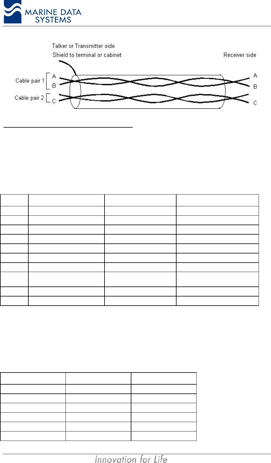
IEC 61162 places certain constraints on the shielding and isolation requirements with
regards to the termination of the duplex Presentation Interface, Pilot, KDU and Long Range
ports. The transmit and receive portions of the IEC 61162 ports must have separate shields.
For this reason, it is recommended to use two separate shielded cables - one for the
transmit section of the port and one for the receive section. For the transmit portion of the
port, the shield of the cable must be connected to the connector shell. The shield for the
receive portion of the port may not be connected at the AIS unit side.
The following general configuration must be followed:
Installation AIMS MIV Manual
22 AIS
Connections to the Presentation Interface
Cable type A
Cable: Two Shielded twisted-cable 2 x 2 pair 0.5mm2.
Maximum cable length: 100m
Cable connector: 9 way D-sub male.
PIN Description TX Cable pair RX Cable pair
1
2
3Input Line A (RX A) 1
4Output Line A (TX A) 1
5Output ground (TX C) 2
6Output Line B (TX B) 1
7
8Input Ground (RX C) 2 (Can also be the shield of the
cable if no Common is available)
9Input Line B (RX B) 1
Shell Shielding Shield of cable Not connected
Cable type D for RS232 connection
Cable: Multi-cable 3 x 0.5mm2 shielded.
Maximum cable length: 15m
Cable connector: 9 way D-sub male.
PIN (AIS unit) Description PC (DTE device)
1No Connection
2Receive Data 2
3Transmit Data 3
4No Connection
5Signal Ground 5
6No Connection
AIMS MIV Manual Installation
AIS 23
PIN (AIS unit) Description PC (DTE device)
7No Connection
8No Connection
9No Connection
Shell of connector Shield Shell of connector
Connect the shield of the cable to the shell of the connector at both sides.
2.7.2.2. Pilot Port
The Pilot Port is electrically identical to the RS 422 Presentation Port. The default data rate
is 38,400 bits/s. It operates on a protocol compliant with IEC 61162-2.
Connections to the Pilot Port
Use Cable type A as described under the Presentation port.
In accordance with the document “Guidelines relating to SOLAS chapter V: Guidelines for
installation of Shipborne Automatic Identification System (AIS)”, the Pilot port shall be
installed on the bridge near the pilot’s operating position, so that the Pilot can connect his
Personal Pilot Unit (PPU) to this point.
This Pilot plug must have the following characteristics:
• Type of plug: AMP/Receptacle. It can be made up to be mounted
permanently to a position or it can be free-hanging.
• The shell size must be 11, 9-pin, Std. Sex 206486-1/2 or equivalent.
The cable connection is as follows:
Pin (AIS DB 9
connector) Connection Pin (AMP Pilot
plug)
1
2
3RX A (Input line A) 5
4TX A (Output line A) 1
5
6TX B (Output line B) 4
7
8
9RX B (Input line B) 6
NC Shield of cable NC
2.7.2.3. KDU (Keyboard Display Unit)
Installation AIMS MIV Manual
24 AIS
The KDU port is electrically identical to the RS 422 Presentation Port and the Pilot Port as
described above. The default data rate is 38,400 bits/s. It operates on a protocol compliant
with IEC 61162-2.
For the layout of the connection at the KDU side, it is advised that the user/installer refer to
the KDU manual (AIMS K1).
Connections to the KDU Port
Use Cable type A as detailed above under Presentation Interface. The cable for connecting
the AIMS M4 to the AIMS K1 would be as follows:
PIN (AIS DE 9
connector) Description TX Cable
pair RX Cable pair PIN (AIMS K1 –
KDU)
1
2
3Input Line A (RX A) 1 9
4Output Line A (TX A) 1 4
5Output ground (TX C) 2 8
6Output Line B (TX B) 1 6
7
8Input Ground (RX C) 2 5
9Input Line B (RX B) 1 3
Shell of DE9 Shield Shield of cable NC
NC Shield Shell of connector
2.7.2.4. Long-Range Communication Port (L/RANGE I/O)
The port is used for connection to a long-range communications terminal, for example
Inmarsat-C. The protocol is according to IEC 61162-2. A conversion may be required
between the Inmarsat C terminal and the AIS unit, depending on the interfaces required.
The port is configured to work at 38,400 bits/s.
Connections to the Long-Range Port
Use Cable type A as detailed above under Presentation Interface.
2.7.2.5. Sensor Input Ports (SENS 1, SENS 2, SENS 3)
The AIS unit is equipped with sensor inputs for position, speed, heading and rate-of-turn.
These ports are input ports only. They are RS 422 IEC 61162-2 protocol and operate at a
default data rate of 4,800 bits/s, but will also auto configure to 38,400 bits/s if equipment
that is connected to these ports has that bit rate. Sensors installed on board the ship for
SOLAS Chapter V shall be connected to the AIS unit. The information that the AIS must
transmit should be the information used for the navigation of the ship. When these sensors
do not have outputs that comply with IEC 61162, the installer will experience interfacing
problems.
AIMS MIV Manual Installation
AIS 25
The ports are used for connecting navigation sensors in accordance with NMEA 0183
standards.
Normally, one of the ports will be connected to the ship’s GPS or other position-fixing
system. The other two sensor ports will normally be connected to the ship’s gyro and ROT
sensor. The sensor ports are interchangeable.
Connections to the Sensor Ports
Cable type C
Cable: Multi-cable 2 x 2 x 0.5mm2 shielded.
Twisted pairs: 3 and 9, 8 and spare
Maximum cable length: 100m
Cable connector: 9 way D-sub male.
PIN Description Cable pair
1
2
3Input Line A (RX A) 1
4
5
6
7
8Input Ground (RX C) 2
9Input Line B (RX B) 1
Shell of connector Shield of cable NC
IMPORTANT NOTE: Do not connect the shield of the cable to any pin on the connector or to the backshell
of the connector. Where a common is not available in the cable, the shield of the
cable may be connected to pin 8 of the connector on the AIMS MIV.
2.7.2.6. DGNSS Port
This is a non-mandatory port provided on the AIS unit that can provide GPS differential
correction data output where an internal Beacon Receiver is fitted (as an option) as well as
providing for an input when an external correction source is available. If will also output
differential data to this port when a differential correction message (message 17) is received
on the VDL.
The default data rate for this port is 4,800 bits/s. The port will operate to recommendation
ITU R.M 823-3 protocol.
Connections to the DGNSS Port
Connection to this port is per Cable Type A.
Installation AIMS MIV Manual
26 AIS
2.7.2.7. Service Port
The service serial port is used to upload software upgrades to the AIS unit. It is a RS232
level three-wire connection operating on a proprietary protocol at various data rates, as it is
driven from the external application.
Refer to Figure 11: Cable Type J Assembly for connector assembly details.
WARNING: This port may only be used by qualified personnel. Permanent connection to
this port is not allowed. The pin assignments on this port is not according to the RS232
specification, since there is a custom pin assignment made.
Connections to the Service Port
Cable type J
Cable: 2 x Multi-cable 5 x 0.5mm2 shielded.
Maximum cable length: 2m
Cable connector: 9 way D-sub male at AIS unit. 2 x 9 way D-sub
female at PC side.
Uploading new software to the AIS unit requires that the connector cable has two multi-core
terminations for programming different sections of the system (the MCM and the SCM) as
illustrated in Figure 11. The two cable terminations are therefore described separately as
follows:
SCM Termination:
AIS unit PIN Description PC PIN
1DSR 4
2Transmit 2
3Receive 3
4CTS 7
5Signal Ground 5
6No Connection
7No Connection
8No Connection
9No Connection
MCM Termination:
AIS unit PIN Description PC PIN
1No Connection
2No Connection
3No Connection
4No Connection
5Signal ground 5
6DSR 4
7Transmit 2
AIMS MIV Manual Installation
AIS 27
AIS unit PIN Description PC PIN
8Receive 3
9CTS 7
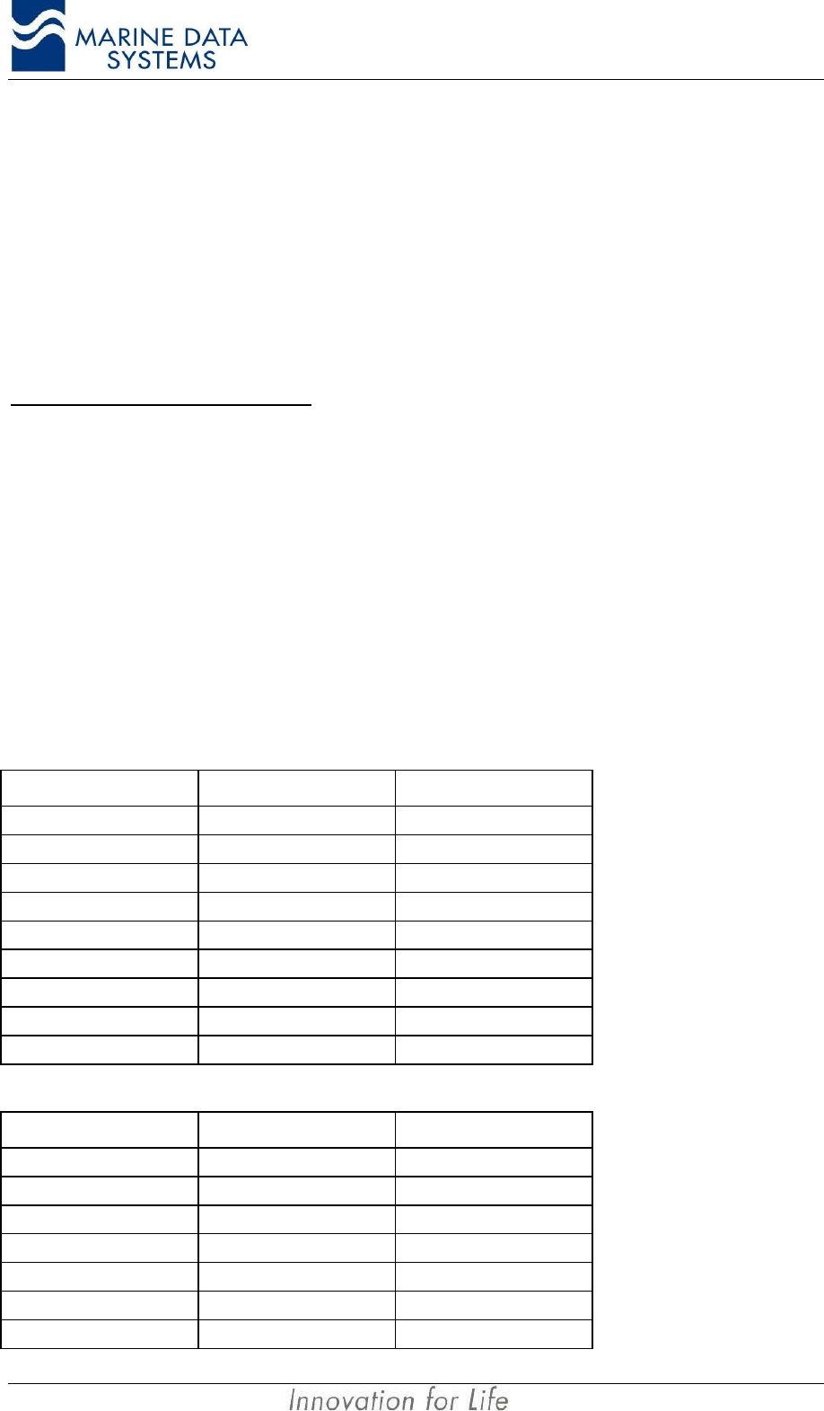
2.7.3. Power Supply Input
The power port will accept a +24VDC supply input. It is internally fused with a 6.3A fuse.
It is recommended that the cable length should not exceed 3m.
Cable type G
A twin core cable with a rated capacity of 10A should be used. The cable must have an
outer diameter of either 5mm or 8mm to fit the power plug supplied with the AIS unit.
24V Power Supply Input Cable
Cable Type Suggested Maximum Length (m)
2 x 0.75mm23
2 x 1.5mm210
2 x 2.5mm215
Power Supply Connector
The connector is a FCI (full plastic Bantam) UTP6104S female. The connector has 4 pins, of
which 2 are used as shown in Figure 9. The supply is galvanically isolated.
Supply Voltage: +24VDC
Fuse: 6.3A.
2.7.4. Alarm Relay Connection
The connector is a FCI (full plastic Bantam) UTP6103S female. The connector has three
pins: 1, 2 and Common as shown in Figure 10. The Common pin is the common connection
for normally open and normally closed connections and the “No Alarm” condition shall be:
• Normally open to pin 1
• Normally closed to pin 2
IMPORTANT NOTE! The common connection must not be connected to the
unit’s ground.
Alarm Relay characteristics
The Alarm changes from “No Alarm” to “Alarm” on the malfunction of any part of the unit.
This alarm connection is designed to be “failsafe”; that is, to activate whenever it is not
Installation AIMS MIV Manual
28 AIS
updated with a “no alarm” for more than 1 minute. The alarm relay will also report an “Alarm”
condition then the AIS unit is powered down.
The relay contacts are rated at 24V, 1A. The relay contacts are galvanically isolated from
the AIS unit housing.
Cable Type H
PIN Description
1Normally Open
2Normally Closed
Ground Common
2.7.5. Cable Assemblies
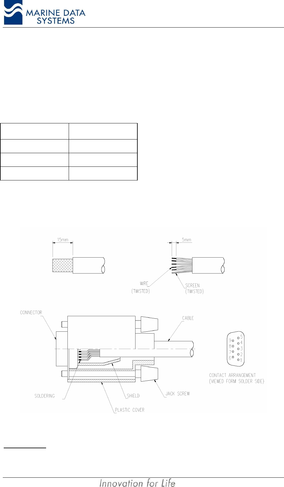
2.7.5.1. Cable Types A, B, C, D
Figure 8: Data Cable Terminations (AIS unit Side)
IMPORTANT: Do not connect the shield of the cable to the shell of the connector for any receiving circuits.
AIMS MIV Manual Installation
AIS 29
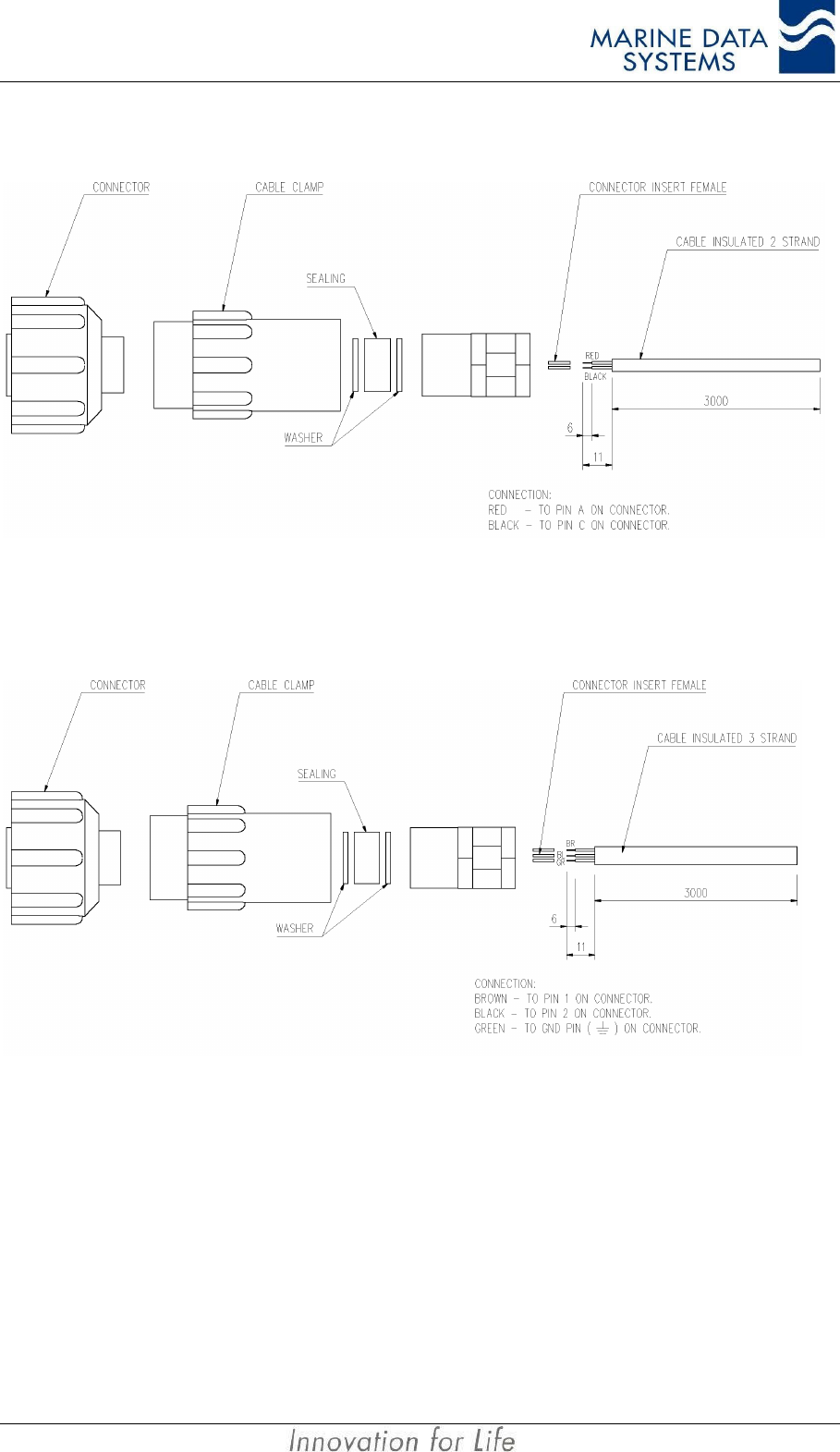
2.7.5.2. Cable Type G Assembly – Power cable
Figure 9: Cable Type G Assembly (AIS unit Side)
2.7.5.3. Cable Type H Assembly – Alarm cable
Figure 10: Cable Type H Assembly (AIS unit Side)
IMPORTANT NOTE: Slide the cable clamps, metal washers and sealing washer over the cable
before pushing the pins into the connector socket portion. The connector
inserts can only be removed from the connector socket with a special tool.
Installation AIMS MIV Manual
30 AIS
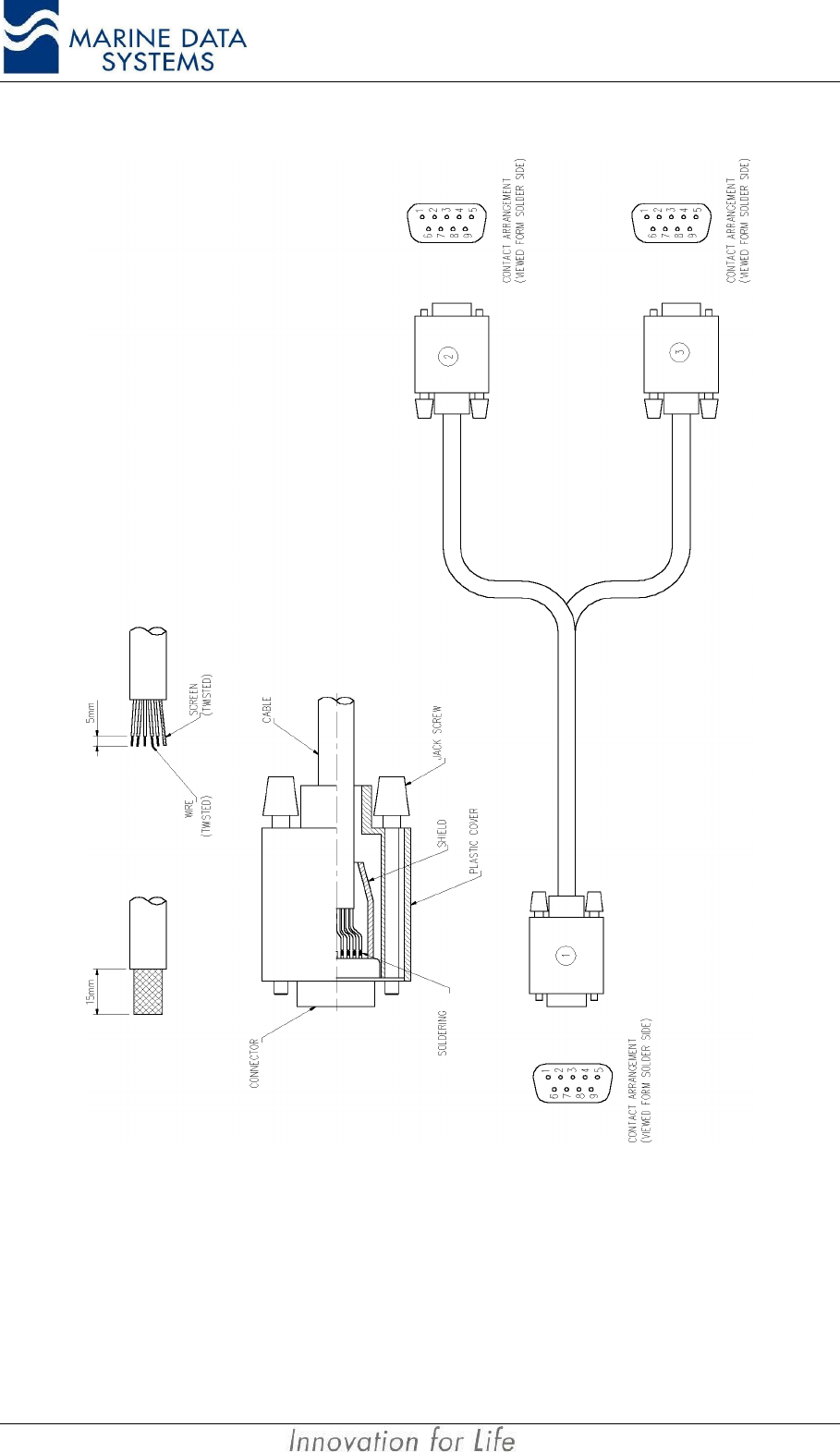
2.7.5.4. Cable Type J Assembly
Figure 11: Cable Type J Assembly
AIMS MIV Manual Installation
AIS 31
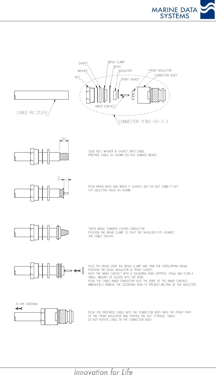
2.7.5.5. Cable Type E, F and L Assembly
Figure 12: Cable type E, F and L Assembly
The drawing shows the fitting of RG 213, but is also valid for RG 214.

Installation AIMS MIV Manual
32 AIS
2.8. Installation Check
Before powering on the AIS unit, the alarm relay must indicate an “Alarm” condition.
Connect the 24 VDC source to the unit. Power on the unit.
The unit will be operational within 2 minutes after switch-on. Sensors will be allowed their
permissible start-up time, that is, 30 minutes for GPS when there is no almanac data
available; this is usually on first time power-up, or power-up in a different geographical
region to that from which the system was shipped.
On boot-up, the system receivers and transmitter are set up for the default AIS and DSC
frequencies.
All LEDs will illuminate when switched on, and the unit will run a self-test. Faults will be
displayed on the LEDs. During the self test, all LED’s (except RS4 if not fitted) will illuminate
red for 2 seconds, then Green for 2 seconds, then the normal status indication will start.
During normal operation, the SCM and MCM LED’s will blink on and off continuously to
indicate normal operation.
Check that the LEDs illuminate in green, and that the alarm does not sound (refer to section
4.1 on page 49).
The alarm relay must have changed to the “No Alarm” condition by now.
AIMS MIV Manual Technical Description
AIS 33
3. TECHNICAL DESCRIPTION
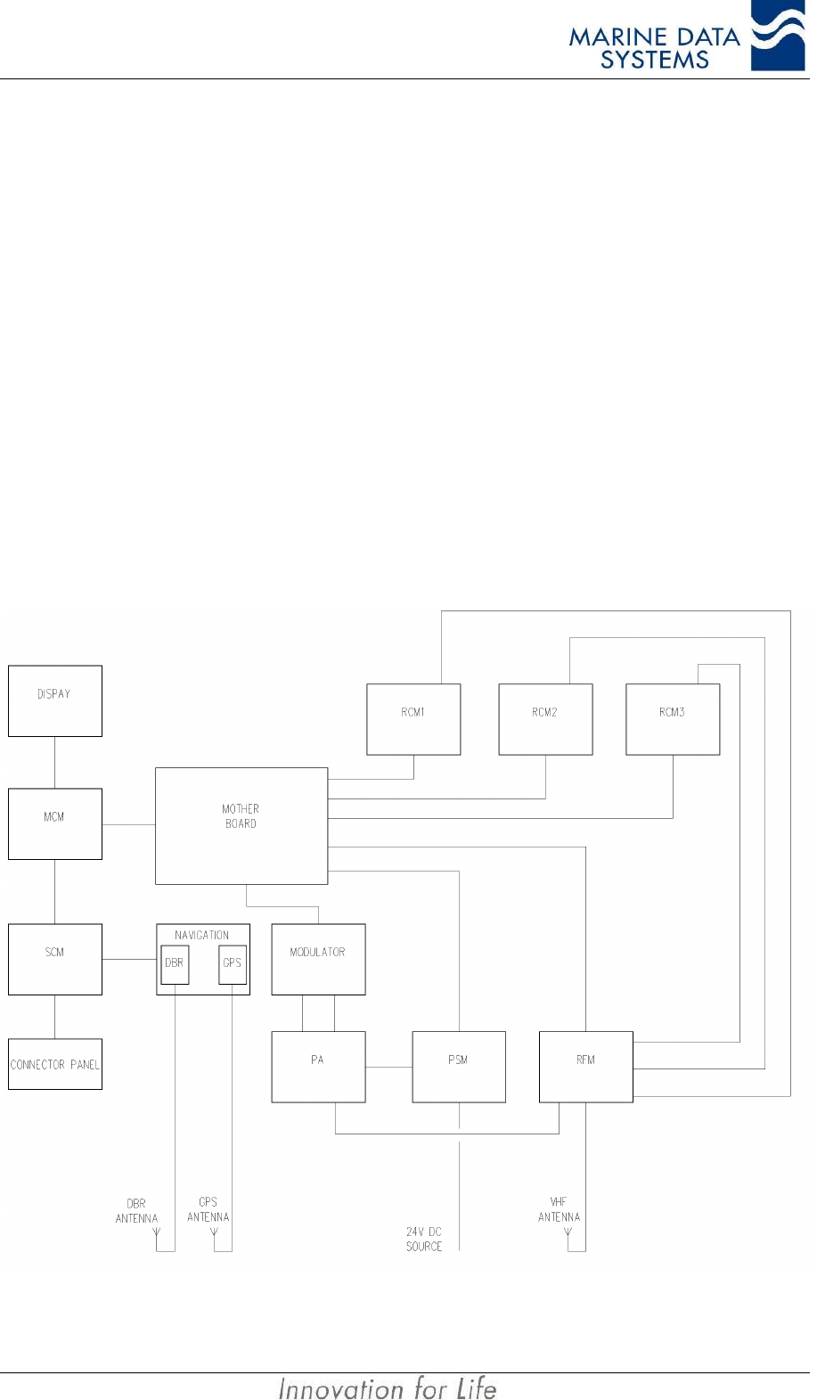
3.1. AIS unit Overview
Each AIS unit consist of:
• Two AIS radio receivers (RCM1 and RCM2)
• One Digital Selective Calling radio receiver (RCM3)
• A Radio Frequency Module (RFM)
• A Power Amplifier Module (PA)
• A Modulator Module (MOD)
• A Power Supply Module (PSM)
• A Main Controller Module (MCM)
• A Serial Communications Module (SCM)
• A Navigation Module with GPS and (optional) Differential Beacon Receiver
• A Motherboard
• A Connector Panel Module,
• A Display Module.
Figure 13: AIS unit Block Schematic

Installation AIMS MIV Manual
34 AIS
3.2. System Modes of Operation
3.2.1. Mobile Station
In this mode, the AIS unit automatically sends out position reports at intervals determined by
the ship’s navigational status and speed. It can send/receive text and binary messages
to/from other AIS units and operates on the AIS and DSC frequencies.
3.3. Serial Communications
3.3.1. Presentation, Pilot and KDU ports
These ports represent 3 different types of display systems that can be used for displaying
AIS target information. The information transmitted by the AIS to external interfaces, will be
available on each of these ports. The roles of the three are as follows:
• Presentation port (RS422 or RS232 ports): Mainly used for connection to display
systems onboard the vessel, such as ECDIS or ECS type systems. It’s also used in
the process of configuring the AIS unit.
• Pilot port (RS422 only): An additional port reserved for use by pilots. This can also
be used to configure the AIS unit.
• KDU port (RS422 only): This port is dedicated for connection of a Keyboard Display
Unit (AIMS K1), as dictated by the AIS specifications. This port can be used to
configure the AIS unit.
Configuration of the AIS unit will require the use of passwords to “unlock” certain areas for
configuration. The correct password will only “unlock” the specified area for 10 seconds,
after which it will return to the “locked” state.
NOTE: All the password values are set to “00000” upon release from the factory. They must be set to
other values by the installer.
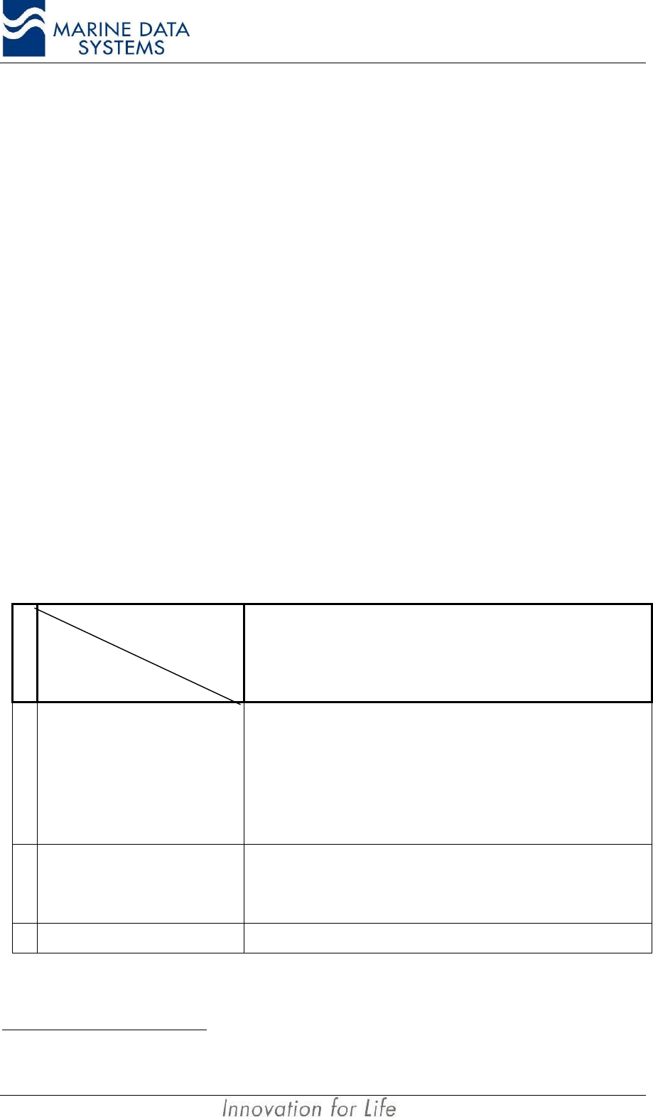
The following is a table of all the international and proprietary sentences that you can expect
to “send to“ and “receive from“ these 3 ports. Additional information on these messages can
be found on the MDS website.
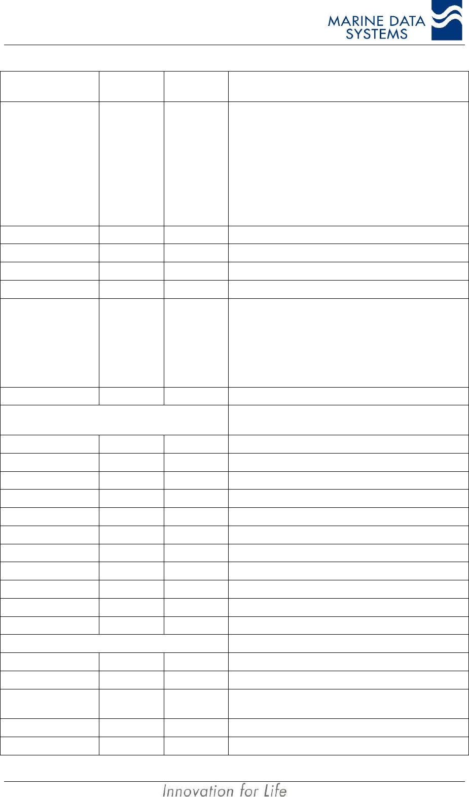
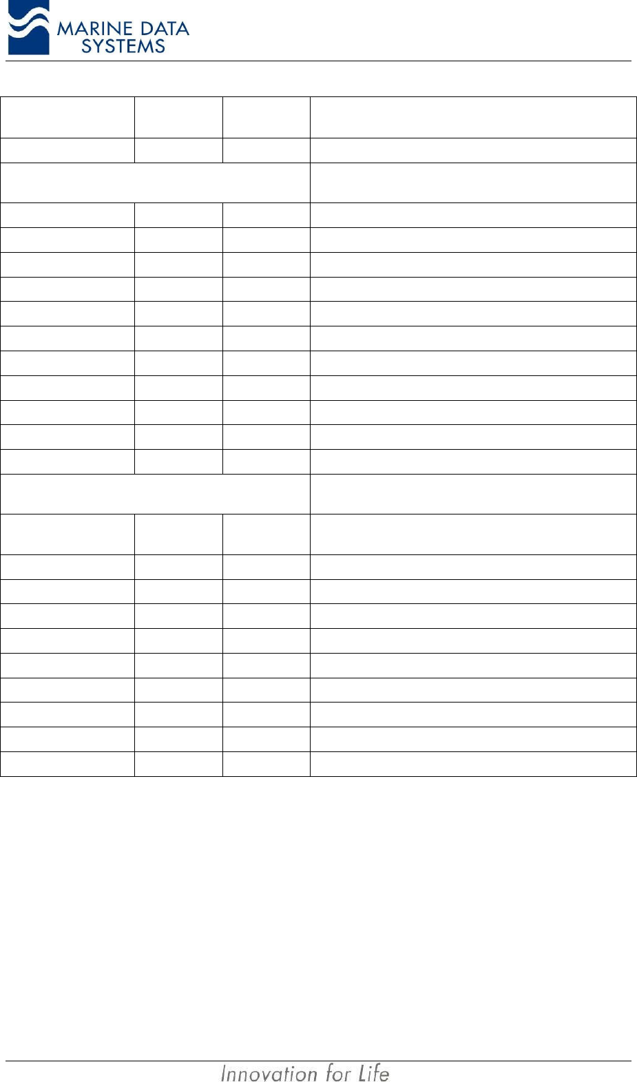
Message
header Message description Reaction of the
system Message
direction
International Sentences
$--VSD
Voyage static data
• Type of ship and cargo
• Maximum present draught
• Persons on board
• Destination
• ETA
• Navigational status
• Regional application flags
Re-program configuration.
Send updated VDL Message 5
and generate VDO message.
Input and Output on
Query
AIMS MIV Manual Technical Description
AIS 35
Message
header Message description Reaction of the
system Message
direction
$--SSD
Ship static data
• Ship’s name
• Call sign
• External GPS source antenna
position
• DTE connected flag
SEE ALSO $PMDSSSD for internal
GPS source antenna position
Re-program configuration
Send updated VDL Message 5
and generate VDO message
Input
Output on Query
!--ABM Addressed Binary Message Send either VDL message 6 or
12, depending on type
requested Input
!--BBM Broadcast Binary Message Send either VDL message 8 or
14, depending on type
requested Input
$--AIR Interrogation message for mobile
stations Send VDL message 15 Input
$--ACK AIS acknowledge message Input
$--ACS Channel Management Information
source Output
$--ACA Channel management message
Input
Output on region
change
$AIABK Addressed binary VDL
acknowledgement Output
!AIVDO Output VDL messages broadcast by
local station Output every one second Output
$AIALR Alarm status Output
$AITXT Sensor and alarm status Output
!AIVDM Output VDL messages received by local
station Output
$--AIQ System information request message Input
Proprietary Sentences
$PMDSACK Proprietary acknowledge message Output
$PMDSCFI Program IMO number Input / Output
$PMDSCFM Program MMSI number Input / Output
$PMDSKDU Input by KDU to indicate it is present
every 10 sec.
Used by AIS unit to
automatically set the DTE flag in
ship static data if so configured Input
$PMDSLED Input to the AIS unit to adjust LED
brightness on display panel. AIS unit adjust LED brightness
to the value in message Input / Output
$PMDSLRC Configure Long-range response. Input / Output
$PMDSLRM Long range manual response. Input
$PMDSLRP Long range poll notification. Initiated from AIS Unit Output
$PMDSMOD Range, model and serial number
request Send in response to RQS Output
$PMDSPRP Output by AIS unit in response to
$PMDSPWD. Output only message, cannot be
queried for Output

Installation AIMS MIV Manual
36 AIS
Message
header Message description Reaction of the
system Message
direction
$PMDSPUP Output by AIS unit after power up Automatically output after power
up Output
$PMDSPWD Input into AIS unit to open security
system or update passwords AIS unit responds with
$PMDSPRP message Input
$PMDSRQS System information request message
More information on retrieval of the
security log in section 4.5.Requested information via the PI Input
$PMDSSEN Output on query by the AIS unit to
indicate the current sensors in use, also
sent out on change of used sensors.
An external unit queries for this
message. Also output when
change of sensors in use occur. Output
$PMDSSLI Security log information Sent on request by $PMDSRQS Output
$PMDSSMC Static Main Controller Module
Configuration Input / Output
$PMDSSSD Ship static data containing the internal
GPS’s antenna position Input / Output
$PMDSTST Input into the AIS unit to switch on/off
output of sensor data Unit output all sensor data on PI
port. Input
$PMDSVDL Used to program default channel
parameters When input, send proprietary
ACK Input / Output
$PMDSVER Output on request, module software
version and serial numbers
Output one message per
module with the appropriate
information Output
$PMDSZDA Output current time and date to KDU Automatically output by AIS unit
every 1 minute during second 0
or when polled for. Output
Table 1: Presentation Interface Messages
During commissioning of the AIS unit, the unit will need to be configured with the ship’s
MMSI and IMO numbers, static and voyage information and other related data. This is done
via the AIMS Utility software or the Keyboard Display Unit (KDU). Only a reduced number of
parameters can be changed via the KDU. Refer to the KDU and Utility Software manuals for
this information. A number of these messages are proprietary see Table 1, for a list of all
the messages.
For the output drive capability and input load see Section 1.2.12. The block diagrams for
the input/output circuits can be found in Figure 17 and Figure 18 on page 58.
The security information can be accessed using the AIMS Utility software supplied with
every unit. Please see the AIMS Utility documentation for more information. The security
log can also be retrieved using a text terminal. Refer to section 4.5 for more details.
If you do not have this software please contact MDS, your local MDS agent or see our
website.
The ship type, as found in the $--VSD message, must be set according to the following
table:
Identifiers to be used by ships to report their type
Identifier
No. Special craft
AIMS MIV Manual Technical Description
AIS 37
50 Pilot vessel
51 Search and rescue vessels
52 Tugs
53 Port tenders
54 Vessels with anti-pollution facilities or equipment
55 Law enforcement vessels
56 Spare – for assignments to local vessels
57 Spare – for assignments to local vessels
58 Medical transports (as defined in the 1949 Geneva Conventions and Additional Protocols)
59 Ships according to Resolution No 18 (Mob-83)
Other ships
First digit (*) Second digit (*) First digit (*) Second digit (*)
1 - reserved for
future use 0 - All ships of this type -0 - Fishing
2 - WIG 1 - Carrying DG, HS, or MP
IMO hazard or pollutant category A -1 - Towing
3 - see right
column 2 - Carrying DG, HS, or MP
IMO hazard or pollutant category B 3 - Vessel 2 - Towing and length of the tow
exceeds 200 m or breadth
exceeds 25 m
4 - HSC 3 - Carrying DG, HS, or MP
IMO hazard or pollutant category C -3 - Engaged in dredging or
underwater operations
5 - see above 4 - Carrying DG, HS, or MP
IMO hazard or pollutant category D -4 - Engaged in diving operations
-5 - reserved for future use -5 - Engaged in military
operations
6 - Passenger
ships 6 - reserved for future use -6 - Sailing
7 - Cargo ships 7 - reserved for future use -7 - Pleasure Craft
8 - Tanker(s) 8 - reserved for future use -8 - reserved for future use
9 - Other types of
ship 9 - No additional information -9 - reserved for future use
Table 2: Vessel and Cargo type
NOTES: DG: Dangerous Goods
HS: Harmful Substances.
MP: Marine Pollutants.
*The identifier should be constructed by selecting the appropriate first and second digits.
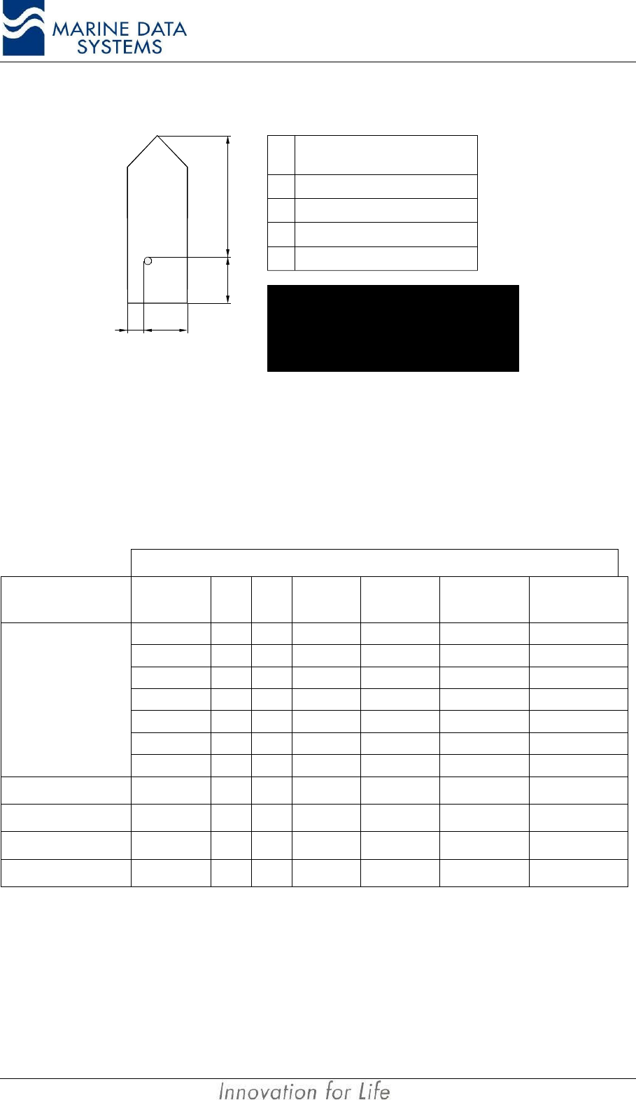
The following figure describes how the position of the EPFS / GPS antenna must be
entered.
Installation AIMS MIV Manual
38 AIS
A
B
DC
A
B
C
D
Distance
(m)
0-511
0-511
0-63;
63 = 63 m or greater
0-63;
63 = 63 m or greater
Reference point of reported position not available, but dimensions
of ship are available: A = C = 0 and B ≠ 0 and D ≠ 0.
Neither reference point of reported position nor dimensions of
ship available; A = B = C = D = 0 (= default)
For use in the message table, A = most significant field,
D = least significant field
Figure 14: Ship dimensions and related fields
3.3.2. Sensor ports (input sentences only)
The AIS Unit must be able to accept various NMEA type sentences from a number of
sensors onboard the vessel. The following section gives detail on how the AIS unit handles
these messages. The AIMS MIV AIS Unit can accept the following messages:
Message Content
Sensor Position SOG COG Heading Rate of
Turn RAIM
Indicator Reference
Datum
GNS
GLL
GGA
RMC RMC RMC
VTG VTG
GBS
GPS
DTM
Gyro HDT
Rate of turn ROT
Radar OSD OSD OSD
Log VBW
When any of the above messages are used, it must be input to the AIS unit at intervals of 1
second.
3.3.2.1. Position and Time:
For position and time information, the GNS and GLL sentences should be used. Optionally
GGA and RMC may be used. All four of these sentences are implemented.
The priority for these sensors is tabulated below:
AIMS MIV Manual Technical Description
AIS 39
Affected data in message 1,2 and 3
Priority
Position Sensor Status
Position
accuracy
flag
Time stamp
RAIM-flag
Position
Longitude/Latitude
1external DGNSS in use (corrected) 1UTC-sec 1/0 Lat/Lon (external)
2internal DGNSS in use (corrected over air: msg 17) 1UTC-sec 1/0 Lat/Lon (internal)
3internal DGNSS in use (corrected; beacon) 1UTC-sec 1/0 Lat/Lon (internal)
4 a external GPS in use (uncorrected)
4 b external non-GPS EPFS in use
0UTC-sec 1/0 Lat/Lon (external)
5internal GNSS in use (uncorrected) 0UTC-sec 1/0 Lat/Lon (internal)
manual pos. input 61 Lat/Lon (manual)
dead reckoning pos. 62 Lat/Lon (dead-reckoning)6no sensor position in use
no position
0
63
0
not available=181/91
Table 3: Position Sensor Precedence
NOTE: * See description of RAIM flag in section RAIM indicator:on page 40
When configuring the position sensor, it must be kept in mind that the Geodatic Datum of
the data transmitted by the sensor is switched to WGS84 and the IEC 61162 DTM sentence
is configured. The AIS assumes WGS84 format if no DTM message is received.
Since AIS is able to process two reference points for the antenna position, one for external
and one for internal, both of them must be configured during installation. If more than one
external reference point is used, the appropriate information must be transmitted to the AIS
unit to adjust the external reference point. This must be done manually via the Presentation
Interface, Pilot Port or KDU port. The $--SSD message must be used for the external
reference point and the proprietary $PMDSSSD message must be used for the internal
reference point.
More than one external GPS (NMEA source with ID = GP, GN or GL) may not be connected
to the AIS unit at the same time. The AIS unit will not be able to distinguish between them
and will assume that they are the same GPS, and use all of them for position fixing. Since
their antennas will probably be at different positions on the ship, it will look to other ships as
if the ship is “jumping around”. There may, however, be one GPS source and one non-GPS
source connected at the same time. This non-GPS source will be used for positioning
according to the priority table, Table 3: Position Sensor Precedence.
NOTE: If a NMEA sentence from a position sensor does not have a checksum, it will be accepted regardless. If,
however the checksum is included, it has to be correct for the message to be used.
3.3.2.2. Speed over ground:
The VBW, VTG, OSD or RMC NMEA sentences are implemented. The Sensor precedence
will give priority to the external sensor for SOG information. Thereafter it will use the active
GPS as source.
Installation AIMS MIV Manual
40 AIS
3.3.2.3. Course over ground:
For COG the RMC, VTG or OSD NMEA sentences are implemented.
3.3.2.4. Heading:
The HDT and OSD NMEA sentences are implemented. A gyrocompass providing heading
information is a mandatory sensor input to the AIS. A converter unit (e.g. stepper to NMEA)
will be needed to connect to the AIS unit if the ship’s gyrocompass does not provide an IEC
61162 output. Only 1 source for heading (HDT) information may be connected to the AIS
unit, e.g. TIHDT or HEHDT. If more than one source is connected it may supply different
information, which will cause the heading information to seem erratic.
3.3.2.5. RAIM indicator:
The GBS NMEA sentence is implemented for this. The error fields indicated are checked to
be non-zero before RAIM active flag is set.
3.3.2.6. Rate of turn:
Some ships do not carry a Rate-Of-Turn (ROT) Indicator according to IMO A.526. However,
if a rate-of-turn indicator is available and it includes an IEC 61162 interface, it shall be
connected to the AIS.
The ROT sentence is implemented for this. ROT is also calculated from heading when ROT
is not available. Refer to Table 4 for an explanation of the precedence used.
Priority
Affected data in
msg 1, 2, 3 ⇒
Position Sensor status
contents of ROT field
1. Rate of Turn Indicator in use 10...+ 126 = turning right at up to 708 degrees per minute or higher;
0...- 126 = turning left at up to 708 degrees per minute or higher
Values between 0 and 708 degrees/min shall be coded by
ROTAIS=4.733 SQRT(ROTsensor) degrees/min
where ROTsensor is the Rate of Turn as input by the external Rate of
Turn Indicator (TI).
Values of 709 degrees per minute and above shall be cut to
708 degrees per minute .
2. other ROT source in use 2+ 127 = turning right at more than 50/30s (No TI available)
0 = no turn
- 127 = turning Left at more than 50/30s (No TI available)
3. no valid ROT information available –128 (80 hex) indicates no turn information available (default)
Table 4: Rate of Turn Sensor Precedence
1 Rate of Turn Indicator according to IMO A.526(13); determined by talker ID
2 i.e. based on HDG information
AIMS MIV Manual Technical Description
AIS 41
3.3.3. Service port
Only service personnel may use this port. It is used for uploading new software to the unit
and for diagnostic purposes.
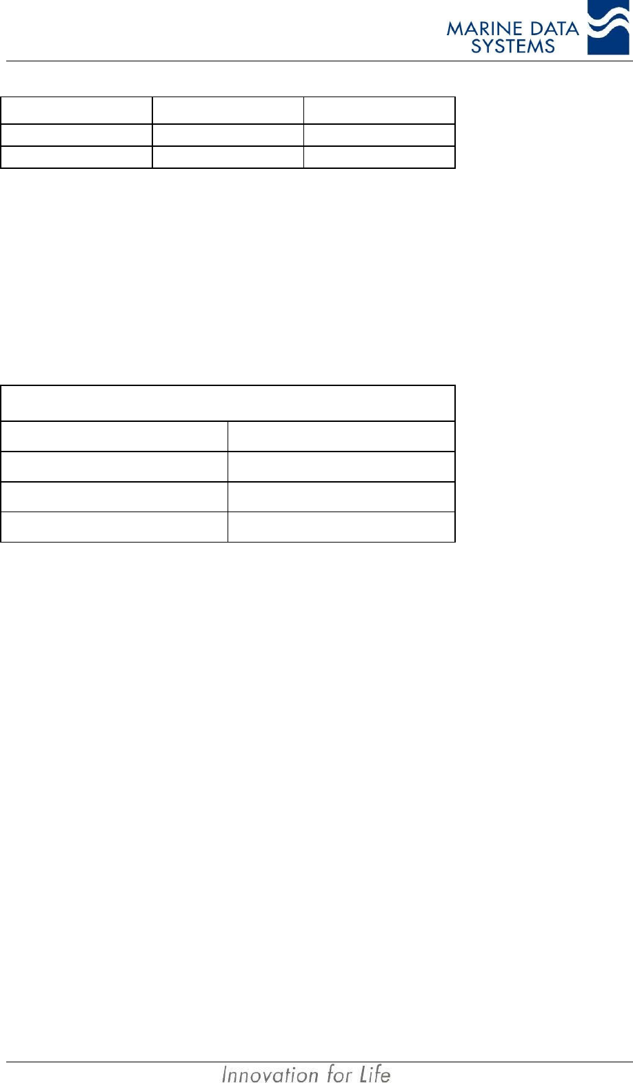
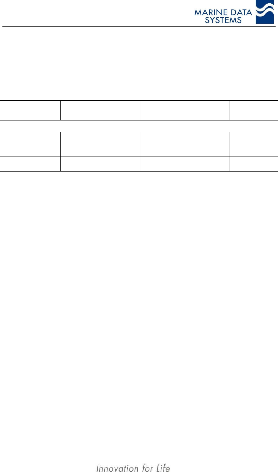
3.3.4. Long Range port
Message header Message description Reaction of the system Message
direction
International Sentences
$--LRF Long range function
message Input/Output
$--LRI Long range interrogation Input
$AILR1, $AILR2 and
$AILR3 Long range responses Output
3.4. Alarm messages
The AIS specification has various standard alarm messages that have been defined. The
AIS unit use all these alarms as well as a number of proprietary alarms.
These alarms and indicators will give the operator a basic idea of what is happening with the
unit itself, as well as with the sensors that are connected to the unit. These messages are
made available on the following interfaces:
• Presentation port,
• Pilot port,
• KDU port.
When using a Terminal emulator the messages would typically be in the following format:
$AIALR,000000,4,V,V,AIS:Rx channel 2 malfunction*37
The alarm ID and description can be found in the following table.
Installation AIMS MIV Manual
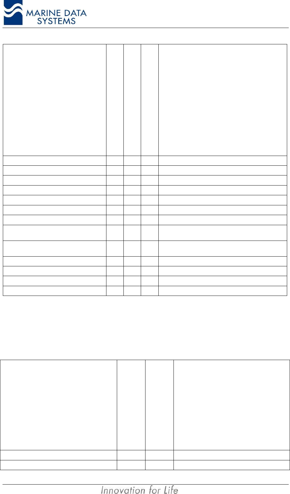
42 AIS
Alarm's description text
Alarm condition threshold
exceeded
Alarm condition not exceeded
Alarm ID or Text Identifier
Reaction of the system to the alarm
condition threshold exceeded
AIS: Tx malfunction A V 001 Stop transmission
AIS: Antenna VSWR exceeds limit A V 002 Continue operation
AIS: Rx channel 1 malfunction A V 003 Stop transmission on affected channel
AIS: Rx channel 2 malfunction A V 004 Stop transmission on affected channel
AIS: Rx channel 70 malfunction A V 005 Stop transmission on affected channel
AIS: General failure A V 006 Stop transmission
AIS: MKD connection lost A V 008 Continue operation with "DTE" set to "1"
AIS: External EPFS lost A V 025 Continue operation (see Table 3: Position Sensor
Precedence on page 39)
AIS: no sensor position in use A V 026 Continue operation (see Table 3: Position Sensor
Precedence on page 39)
AIS: no valid SOG information A V 029 Continue operation using default data
AIS: no valid COG information A V 030 Continue operation using default data
AIS: Heading lost/invalid A V 032 Continue operation using default data
AIS: no valid ROT information A V 035 Continue operation using default data
Table 5: AIS Standard alarm messages
These standard alarm messages does not provide all the information necessary for
technical staff to assess the problem, so a proprietary set of Alarms were defined.
Proprietary alarm numbers are reported by using the international NMEA alarm message
with alarm ID’s in the range 51 to 99 as defined below.
Alarm’s description text
Alarm or text message
Message ID
Reaction of the system
AIS: Power supply BIT failure ALR 51 Stop transmission
AIS: SCM BIT failure ALR 52 Stop transmission
AIMS MIV Manual Technical Description
AIS 43
Alarm’s description text
Alarm or text message
Message ID
Reaction of the system
AIS: MCM BIT failure ALR 53 Stop transmission
AIS: RCMx GMSK modem faulty TXT 60 Stop transmission on this channel
AIS: RCMx FSK modem faulty TXT 61 Stop transmission on this channel
AIS: RCMx correlator faulty TXT 62 Stop transmission on this channel
AIS: RCMx Lock detect 1 faulty TXT 63 Stop transmission on this channel
AIS: RCMx Lock detect 2 faulty TXT 64 Stop transmission on this channel
AIS: RCMx modem in wrong slot TXT 65 Stop transmission on this channel
AIS: RCMx slot clock absent TXT 66 Stop transmission on this channel
AIS: RCMx code checksum failed TXT 67 Stop transmission on this channel
AIS: TCM GMSK modem faulty TXT 76 Stop transmission
AIS: TCM FSK modem faulty TXT 77 Stop transmission
AIS: TCM PA is shut down TXT 78 Stop transmission
AIS: TCM lock detect 2 faulty TXT 79 Stop transmission
AIS: TCM forward power over threshold TXT 80 Continue operation
AIS: TCM reflected power over threshold TXT 81 Continue operation
AIS: TCM PA temperature shutdown TXT 82 Stop transmission
AIS: TCM PA temperature forced low power TXT 83 Continue operation
AIS: TCM slot clock absent TXT 84 Stop transmission
AIS: TCM code checksum failed TXT 86 Stop transmission
Table 6: Proprietary alarm definitions
NOTES:
• For alarm numbers 60 to 67 valid values for RCMx are x=1 to x=4. When a message is output for
alarm 60 to 67, the text string will indicate from which RCM the alarm originated. I.e. an alarm for
RCM 1 will show the alarm string “AIS: RCM1 GMSK modem faulty”. These text string are output to
give additional information on ALR id’s 003 to 005.
• Text messages 80 and 81 above are output together with ALR 002.
• Text messages 76 to 79, 82, 84 and 86 are output as additional info with ALR 001.
• Text id 83 is output by itself – cause no ALR message.
• On alarm event - an ALR sentence will be output with 'Alarm condition' set to 'A' and 'Alarm ack state'
set to 'V' indicating alarm activated - not acknowledged. When the ACK message is used to
acknowledge and alarm (with corresponding ID) the alarm output every 30 sec will change to 'Alarm
condition' set to 'A' and 'Alarm ack state' set to 'A' indicating alarm and acknowledged. When the
alarm condition is cleared an ALR sentence will be output once with 'Alarm condition' set to 'V' to
Installation AIMS MIV Manual
44 AIS
indicate that the alarm condition is cleared. The 'Alarm acknowledge state' will be set to it's current
condition and can be ignored.
All text messages in the table above will be output once, when the alarm activates – they will
not be output every 30 seconds with the alarm.
3.5. Status messages
Alarm’s description text
Alarm or text message
Message ID
Reaction of the system
System status TXT 90 Outputs system status
Channel settings TXT 91 Outputs VDL channel settings
Table 7: Proprietary status messages
These messages are output to the Presentation ports once every 10 seconds. The
information on these messages can be requested from MDS or refer to the MDS website.
3.6. AIS Receiver Module (RCM 1 or 2)
The AIS receiver modules receive the VDL transmissions from other AIS units. These
modules form an integral and important part of the operation of an AIS unit. It is therefore
important that these units perform self-testing procedures in order to ensure proper
functionality.
An alarm message relating to the specific receiver will be generated as follows:
• Receiver 1 failed – ALR with ID 3
• Receiver 2 failed – ALR with ID 4
• Receiver channel 70 failed – ALR with ID 5
For more detail about the additional information that is supplied also see Table 6 on page
43.
3.7. Usage of NMEA sentences
The following table describes the NMEA sentences as implemented in the AIMS MIV unit:
Message Header Message
Field Not Used /
Used Description
$--DTM, ccc, a, x.x, a, x.x, a, x.x, ccc, Datum Reference
AIMS MIV Manual Technical Description
AIS 45
Message Header Message
Field Not Used /
Used Description
ccc, Not Used Local datum code
WGS84=W84
WGS72=W72
SGS85=S85
PE90=P90
User defined=999
IHO datum code
a, Not Used Local datum subdivision code
x.x,a, Not Used Latitude offset (minutes)
x.x,a, Not Used Longitude offset (minutes)
x.x, Not Used Altitude offset (meters)
ccc, Used Reference datum code
WGS84=W84
WGS72=W72
SGS85=S85
PE90=P90
$--GNS, hhmmss.ss, llll.ll, a, yyyyy.yy, a, c--c,
xx, x.x, x.x, x.x, x.x, x.x, GNSS Fix Data
hhmmss.ss Not Used UTC
llll.ll,a Used Latitude
yyyyy.yy,a Used Longitude
c--c, Used Mode indicator
xx, Not Used Nr of satellites in use
xx, Not Used HDOP
x.x, Not Used Antenna altitude (meters)
x.x, Not Used Geoidal separation (meters)
x.x, Not Used Age of differential data
x.x Not Used Diff reference station ID
$--GLL, lll.ll, a, yyyyy, a, hhmmss.ss, A, a, Geographic Position - Latitude / Longitude
llll.ll,a Used Latitude
yyyyy,yy,a Used Longitude
hhmmss.ss
,Used UTC of position
A, Used Status
a, Used Mode
Installation AIMS MIV Manual
46 AIS
Message Header Message
Field Not Used /
Used Description
$--GGA, hhmmss.ss, llll.ll, a, yyyyy.yy, a, x, xx,
x.x, x.x, M, x.x, M, x.x, xxxx Global Positioning System Fix Data
hhmmss.ss Used UTC of position
llll.ll,a Used Latitude
yyyyy.yy,a Used Longitude
x, Used GPS quality indicator
xx Not Used Number of satellites in use
x.x, Not Used Horizontal dilution of precision
x.x,M, Not Used Altitude (meters)
x.x,M, Not Used Geoidal separation (meters)
x.x, Not Used Age of differential GPS data
xxxx, Not Used Differential reference station ID
$--RMC, hhmmss.ss, A, llll.ll, a, yyyyy, a, x.x,
x.x, xxxxxx, x.x, a, a, Recommended Minimum Specific GNSS Data
hhmmss.ss
,Used UTC (used to sync 1PPS time - odd even second)
A, Used status
llll.ll,a, Used Latitude
yyyyy.yy,a, Used Longitude
x.x, Used Speed Over Ground
x.x, Used Course Over Ground
xxxxxx, Used Date ddmmyy
x.x,a, Not Used Magnetic variation (degrees)
a, Used Mode indicator
AIMS MIV Manual Technical Description
AIS 47
Message Header Message
Field Not Used /
Used Description
$--VBW, x.x, x.x, A, x.x, x.x, A, x.x, A, x.x, A, Dual Ground/Water Speed
x.x, Not Used Longitudinal water speed (knots)
x.x, Not Used Transverse water speed (knots)
A, Not Used Status, water speed
x.x, Used Longitudinal ground speed (knots)
x.x, Used Transverse ground speed (knots)
A, Used Status, ground speed
x.x, Not Used Stern transverse water speed (knots)
A, Not Used Status stern water speed
x.x, Not Used Stern transverse ground speed (knots)
A, Not Used Status stern ground speed
$--VTG x.x, T, x.x, M, x.x, N, x.x, K, a, Course Over Ground and Ground Speed
x.x,T, Used Course over ground, degrees True
x.x,M, Not Used Course over ground, degrees Magnetic
x.x,N, Used Speed over ground (knots)
x.x,K, Used Speed over ground (km/hr)
a, Used Mode indicator
$--OSD, x.x, A, x.x, a, x.x, a, x.x, x.x, a, Own Ship Data
x.x, Used Heading, degrees True
A, Used Heading status
x.x, Used Vessel course, degrees True
a, Used Course reference
x.x, Used Vessel speed
a, Used Speed reference
x.x, Not Used Vessel set, degrees True
x.x, Not Used Vessel drift (speed)
a, Used Speed units, K/N/S
$--HDT, x.x, T Heading, True
x.x,T Used Heading, degrees True
Installation AIMS MIV Manual
48 AIS
Message Header Message
Field Not Used /
Used Description
$--GBS, hhmmss.ss, x.x, x.x, x.x, xx, x.x, x.x,
x.x, Global Satellite Fault Detection
hhmmss.ss
,Not Used UTC time of GGA or GNS fix associated with this
sentence
x.x, Used Expected error in Latitude
x.x, Used Expected error in Longitude
x.x, Not Used Expected error in altitude
xx, Not Used ID nimber of most likely failed satellite
x.x, Not Used Probability of missed detection of most likely failed
satellite
x.x, Not Used Estimate of bias in meters of most likely failed
satellite
x.x, Not Used Standard deviation of bias estimate
$--ROT,x.x,A Rate Of Turn
x.x, Used Rate of turn
A, Used Status
Table 8 : NMEA message usage
AIMS MIV Manual Service
AIS 49
4. SERVICE
4.1. Explanation of the LEDs
The status LED’s are located on the front panel of the AIS unit. This gives the operator or
user a basic indication of the status of each of the modules within the unit. Use the
following table as a guide to understanding what each LED indication means.
RX
BASE
MODE
REPEATER
MODE
MAIN
CONTR.
AIS
RX1
DSC
RX3 ANT
POSITION
FIX
DIFF.
FIX
TRANSM.
RX4
AIS
RX2
SERIAL
CONTR.
POWER
SUPPLY
MOBILE
MODE
TX
Figure 7: AIS unit Front Panel LEDs
Function Indicators
LED Explanation
RX This LED flashes Green when a message is received
TX This LED flashes Green when a message is transmitted
Base Mode This LED is illuminated when the AIS unit is operated as a base unit
Mobile Mode This LED is illuminated when the AIS unit is operated as a mobile unit, that is, on a ship
Repeater Mode This LED is illuminated when the AIS unit is operated as a repeater unit
System Indicators
LED Description Normal operation Fault condition
Power Supply This LED is illuminated when the AIS unit is switched on and Power Supply is working.
Main Contr Main Controller Flashing green Fixed red
Serial Contr Serial Controller Flashing green Fixed red
AIS RX1 AIS Receiver number 1 Fixed green Fixed red
AIS RX2 AIS Receiver number 2 Fixed green Fixed red
DSC RX3 DSC Receiver Fixed green Fixed red
RX4 (*) Optional AIS Receiver Fixed green (*) Fixed red (*)
TRANSM Transmitter Fixed green Fixed red
ANT Antenna (VSWR indicator) Fixed green Fixed red
POSITION FIX Internal GPS receiver Fixed green while in GPS
lock Fixed red when no GPS
lock
DIFF. FIX (*) Optional Internal DBR
receiver Fixed green (*) Fixed red (*)
Table 9: LED Operation
NOTES: *When this option is not fitted, the LED will be off.

Service AIMS MIV Manual
50 AIS
4.2. System Indicators (additional information)
4.2.1. DIFF. FIX
If the AIS unit is functioning with differentially corrected data from an internal or external
sourse, this LED will be green, otherwise it will be red.
4.2.2. Receiver failure
The AIS unit can detect a receiver failure using the methods described in section 3.6 on
page 44.
Once the AIS unit has determined that there has been a receiver failure, it will raise an
alarm. The type of alarm will relate to the specific receiver that has failed (please see
section 3.4 on page 41 for more detail of the various alarm messages.
4.3. Alarm relay
The alarm output is a double throw relay contact. This can be used to activate an external
alarm when the unit malfunctions. The alarm can be de-activated by user intervention on
the Keyboard Display Unit or Primary Display Unit.
The alarm will sound if there is:
• no GPS lock,
• a faulty module,
• a faulty antenna,
• a power failure,
• loss of sensor data,
• no communication with KDU.
See Table 5 in Section 3.4 on page 41 for more detail of the various alarm messages.
4.4. Troubleshooting
IMPORTANT NOTE: The unit should only be opened by qualified personnel.
When a fault occurs, switch off the unit and have the faulty module replaced by a suitably
qualified technician.
4.5. Security log retreival
The AIMS MIV unit keeps track of how often the unit has been switched off for more than10
minutes. This log can be retrieved from the AIS unit using a text terminal or the AIMS utility
software.
To retrieve the message using a text terminal, a serial cable must be connected to the
Presentation , KDU or Pilot Port. The following message is sent into the port to activate the
retrieval:
$PMDSRQS,5000,MDSSLI

AIMS MIV Manual Service
AIS 51
There must be a <cr><lf> at the end of the line above. (Entered by pressing ENTER on a
PC)
The output data from the port will look like this:
$PMDSSLI,5000,02,11,05,111821,02,11,05,133644,2559.8425,S,02803.6809,E*50
$PMDSSLI,5000,02,11,08,094409,02,11,08,100058,2559.8446,S,02803.6901,E*5D
$PMDSSLI,5000,02,11,08,133327,02,11,11,121708,5330.7792,N,01000.9818,E*4B
$PMDSSLI,5000,02,11,14,112833,02,11,14,115441,2559.8464,S,02803.6901,E*5F
$PMDSSLI,5000,02,11,18,100628,02,11,18,120032,9100.0000,N,18100.0000,E*41
$PMDSSLI,5000,02,11,22,093855,02,11,22,095852,2550.7792,S,02814.9818,E*5C
$PMDSSLI,5000,02,11,22,150124,02,11,26,123426,2550.7792,S,02814.9818,E*5A
There is one line for every entry in the security log. As an example, the first line is explained
below:
5000 - Message sequence number
02 - Number of years since the year 2000 at power off for this data entry
11 - Month at power off for this entry
05 - Day at power off for this entry
111821 - UTC time at power off for this data entry
02 - Years since year 2000 at power on for this entry
11 - Month at power on for this entry
05 - Day at power on for this entry
133644 - UTC time at power on for this entry
2559.8425,S - Switch off Latitude if available for this entry
02803.6809.E - Switch off Longitude if available for this entry
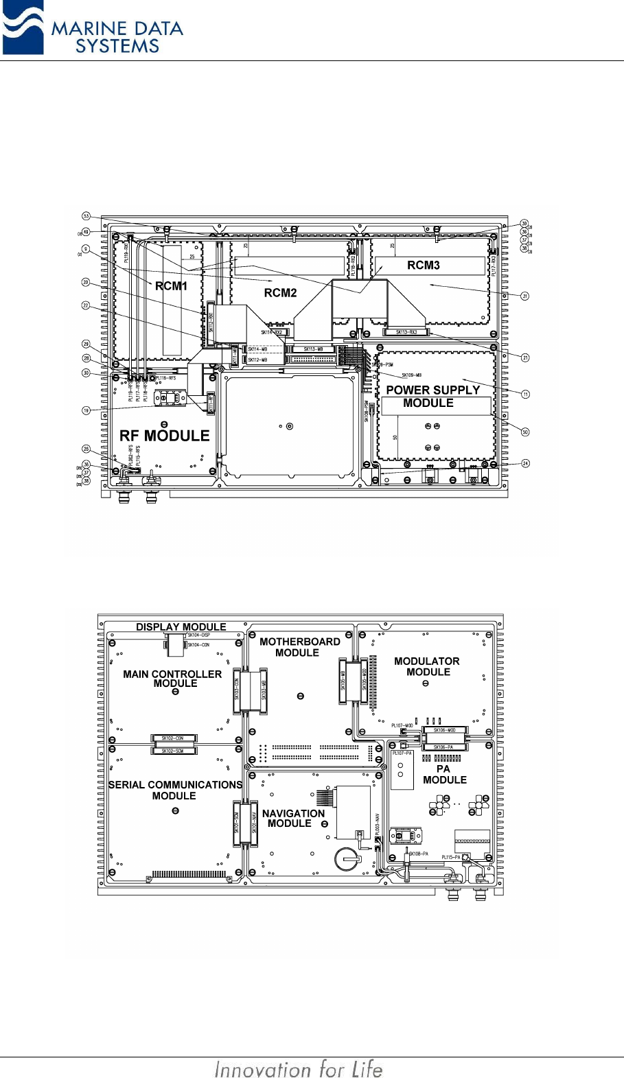
Service AIMS MIV Manual
52 AIS
4.6. Replacing the Modules
Modules may be replaced by removing the top or bottom cover and unplugging the module
from its position after removal of the fixing screws and washers.
Figure 15: AIS unit Module Layout (bottom view)
Figure 16: AIS unit Module Layout (top view)
AIMS MIV Manual Service
AIS 53
IMPORTANT NOTICE:
If modules have been changed, please observe the following:
• If the MCM has to be replaced, the module will need to be reprogrammed
with the ship’s static, voyage and other configuration data.
• If the NAV module has to be replaced, there will be a waiting period of up to
30 minutes for the GPS to lock onto the satellites.
• The SCM and MCM modules can only be replaced if the replacement
modules have software preloaded, otherwise new software must be uploaded
via the Service Port using the ‘AMDT AIS unit Flash Utility’.
Appendices AIMS MIV Manual
54 AIS
5. APPENDICES
5.1. Abbreviations
The following is a list of abbreviations use in this technical manual:
1pps 1 pulse per second
ACK Acknowledge
AIMS Automatic Identification and Data Management System
AIS Automatic Identification System
AIS1 Automatic Identification System channel 1 (161.975 MHz)
AIS2 Automatic Identification System channel 2 (162.025 MHz)
ANT Antenna
BER Bit Error Rate
BIT Built In Self Test
BS Base Station
BSM Base Station Mode
BT Bandwidth Time product
COG Course over Ground
DBR Differential Beacon Receiver
DSC Digital Selective-Calling
DTE Data Terminal Equipment
ECDIS Electronic Chart Display and Information System
ECS Electronic Chart System
EPFS Electronic Position Fixing System
ETA Estimated Time of Arrival
GPS Global Positioning System
HDLC High-level Data Link Control
HSC High Speed Craft
IEC International Electro-technical Commission
IO Input-Output
ISO International Organisation for Standardisation
AIMS MIV Manual Appendices
AIS 55
ITU International Telecommunication Union
KDU Keyboard Display Unit
LR Long Range
MCM Main Controller Module
MDS Marine Data Systems
MMSI Maritime Mobile Service Identities
NU Not Used
PA Power Amplifier
PC Personal Computer
PER Packet Error Rate
PI Presentation Interface
PSM Power Supply Module
RCM Receive Channel Module
RF Radio Frequency
RFM Radio Frequency Module
ROT Rate of Turn
RX Receive
SCM Serial Communications Module
SOG Speed over Ground
TCM Transmit Channel Module
TDMA Time Division Multiple Access
TX Transmit
UTC Coordinated Universal Time
VDL VHF Data Link
VHF Very High Frequency
VSWR Voltage Standing Wave Ratio

Appendices AIMS MIV Manual
56 AIS
5.2. Reference Documents
5.2.1. List of standards and specifications:
Document Number Title
IEC 61162-1 Maritime Navigation and Radio Communication Equipment and Systems - Digital
Interfaces: Part 1 - Single Talker and Multiple Listeners.
IEC 61162-2 Maritime Navigation and Radio Communication Equipment and Systems - Digital
Interfaces: Part 2 - Single Talker and Multiple Listeners High Speed Transmission.
IEC 61993-2 IS Universal Shipborne Automatic Identification System (AIS).
ISO/IEC 3309, 1993 Information Technology telecommunication and informational exchange between
systems - HDLC procedures - Frame Structure.
ITU-R M.1084-2 Interim solutions for improved efficiency in the use of Band 156-174 MH by
stations in the Maritime Mobile Service.
ITU-R M.1371-1 Technical characteristics for a universal ship-borne automatic identification system
using time division multiple access in the maritime mobile band.
ITU-R M.493 Digital Selective Calling (DSC) system for use in the Maritime Mobile Service.
ITU-R M.823-2 Technical characteristics of differential transmissions for global navigation satellite
systems from maritime radio beacons in the frequency band 283.5 - 315 kHz in
region 1 and 285-325 kHz in regions 2 and 3.
ITU-R M.825-3 Characteristics of a transponder system using DSC techniques for use with vessel
traffic services and ship-to-ship identification.
ITU Manual ITU Manual for use by the Maritime mobile and Maritime Mobile-Satellite Services.
IEC 61108-1 Global navigation satellite systems (GNSS) - Part 1: Global positioning system
(GPS) - Receiver equipment - Performance standards, methods of testing and
required test results.
ISO 9000-3 Guidelines for the development, supply, installation and maintenance of computer
software.
IEC/EN 60945 Maritime Navigation and Radiocommunication equipment and systems – General
requirements-methods of testing and required results

AIMS MIV Manual Appendices
AIS 57
5.2.2. List of Related Software and Manuals:
Module Description Part number
AIMS Utility Software for Windows A Windows based utility for configuring and testing the
AIMS range of products. Various levels of user access
available.
AIMS Utility Software User Manual User Manual
AIMS Utility for PalmOS A PalmOS based utility for configuring the AIMS range
of products
AIMS Utility for PocketPC 2002 A PocketPC based utility for configuring the AIMS range
of products
AIMS Utility for PDA User Manual User Manual
AIMS K1 User Manual A Keyboard Display Unit that conforms to the
requirements as laid out by the IMO
AMDT AIS Unit Flash Utility A utility for upgrading the AIMS MIV unit software
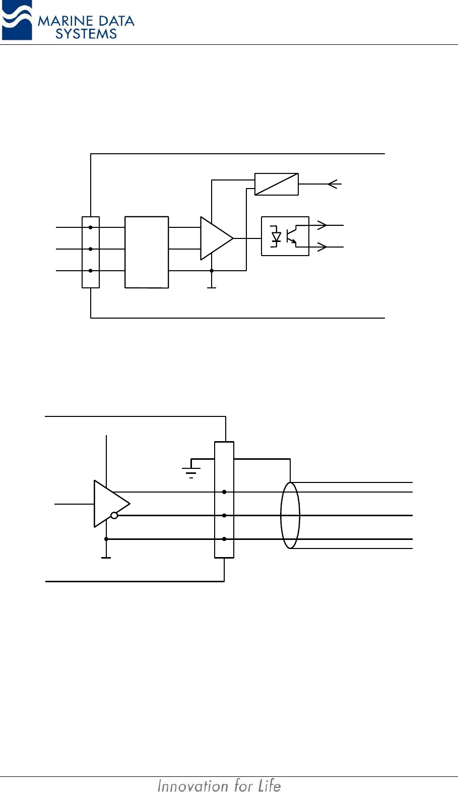
Appendices AIMS MIV Manual
58 AIS
5.3. AIMS Serial interface “Listener” and “Talker” circuit diagrams
This section will give a basic circuit diagram of the RS422 input and output circuits of the
AIS Unit.
Protec-
tion
Common
(isolated)
Opto
isolator
Isolating
power supply
To internal
electronics
A
B
C
Listener
Figure 17. RS422 General “Listener” circuit diagram
Common
A
B
C
Talker
VCC
SHIELD
Figure 18. RS422 General “Talker” circuit diagram

NOTES:
AIS 59

580 Kyalami Boulevard
Kyalami Business Park
Kyalami
Midrand
South Africa
Tel: +27 11 549 1800
www.marinedata.co.za
email: support@marinedata.co.za