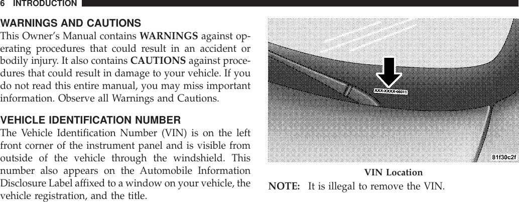
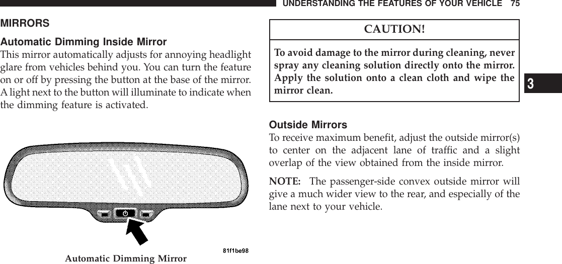
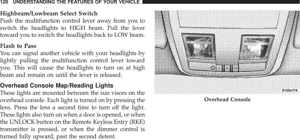
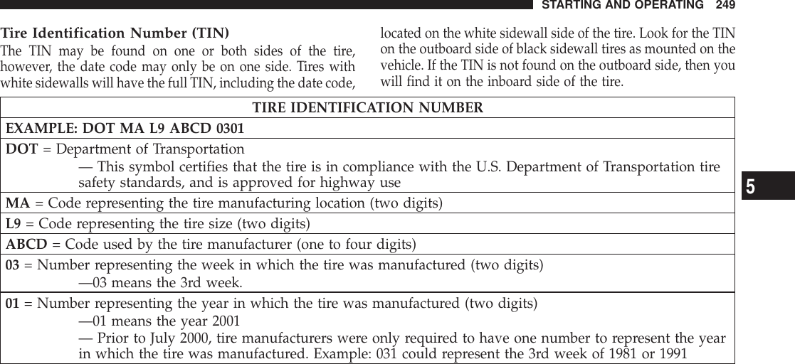
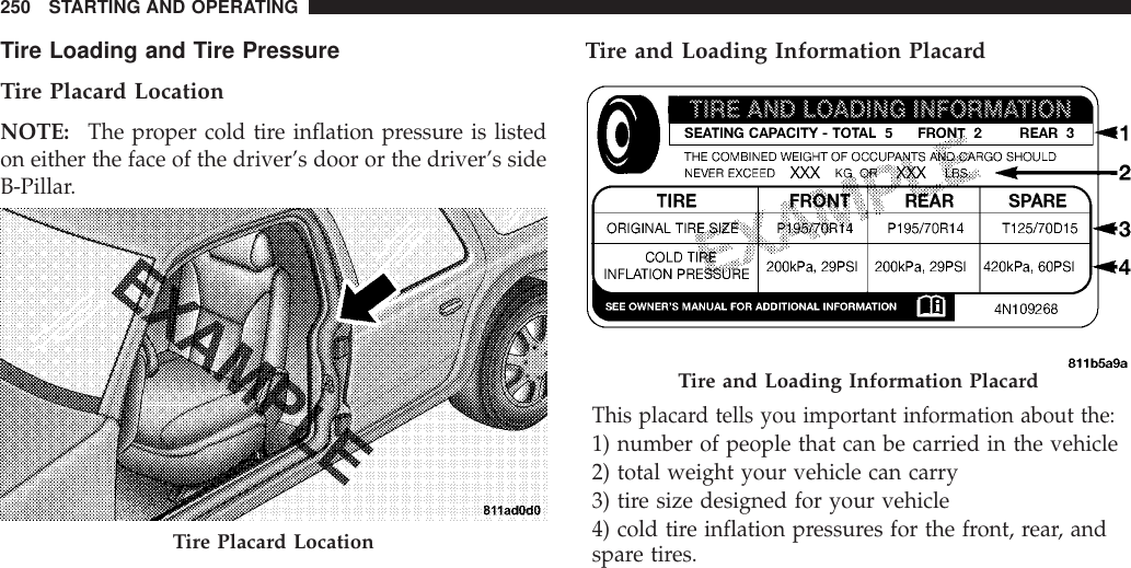
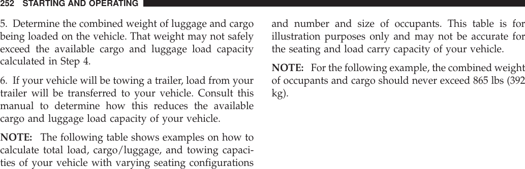
Marquardt C01B Remote Keyless Entry Device and Integrated Vehicular Receiver User Manual 2008 Dodge LC22 Challenger SRT8
Marquardt GmbH Remote Keyless Entry Device and Integrated Vehicular Receiver 2008 Dodge LC22 Challenger SRT8
UserManual.wiki
>
Marquardt
>
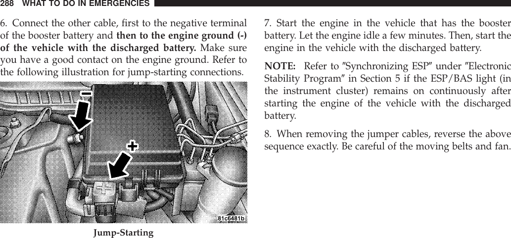
C01B User Manual
User Manual
Navigation menu
Upload a User Manual
Namespaces
Wiki Guide
HTML
PDF
Info
Views
User Manual
Discussion / Help
Navigation
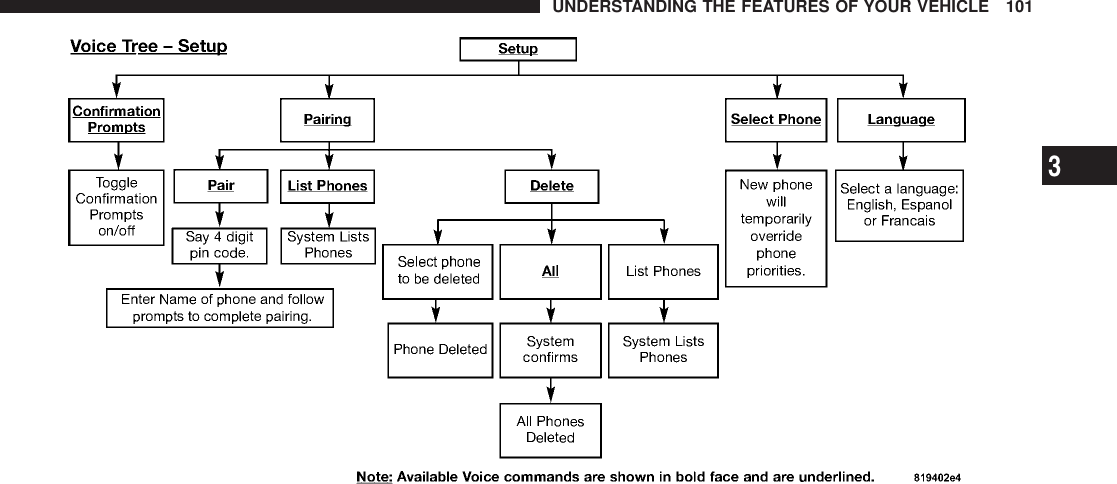
![•When prompted, say 9List Phones.9•The UConnecttsystem will play the phone names ofall paired cellular phones in order from the highest tothe lowest priority. To “select” or “delete” a pairedphone being announced, press the “Voice Recogni-tion” button and say “Select” or “Delete.”Also, see thenext two sections for an alternate way to “select” or“delete” a paired phone.Select Another Cellular PhoneThis feature allows you to select and start using anotherphone paired with the UConnecttsystem.•Press the PHONE button to begin.•After the 9Ready9prompt and the following beep, say9Setup Select Phone9and follow the prompts.•You can also press the “Voice Recognition” button atany time while the list is being played, and thenchoose the phone that you wish to select.•The selected phone will be used for the next phonecall. If the selected phone is not available, theUConnecttsystem will return to using the highestpriority phone present in or near (approximatelywithin 30 ft [9 m]) the vehicle.Delete UConnecttPaired Cellular Phones•Press the PHONE button to begin.•After the 9Ready9prompt and the following beep, say9Setup Phone Pairing.9•At the next prompt, say 9Delete9and follow theprompts.•You can also press the “Voice Recognition” button atany time while the list is being played, and thenchoose the phone you wish to delete.UNDERSTANDING THE FEATURES OF YOUR VEHICLE 953](https://usermanual.wiki/Marquardt/C01B/User-Guide-1046980-Page-97.png)
![•Surround Sound Modes (If Equipped with Driver-Selectable Surround [DSS])•Performance FeaturesThe system allows the driver to select information bypressing the following buttons mounted on the steeringwheel.MENU ButtonPress and release the MENU button and themode displayed will change between TripFunctions, Performance Pages, Navigation (IfEquipped), System Warnings, System Status,Personal Settings, Telephone (If Equipped), and Sur-round Sound (If Equipped).FUNCTION SELECT ButtonPress the FUNCTION SELECT button to accepta selection. The FUNCTION SELECT buttonalso functions as a remote sound system control. Refer to“Remote Sound System Controls” in this section.SCROLL ButtonPress the SCROLLbutton to scroll through TripFunctions, Performance Pages, Navigation (IfEquipped), System Status Messages, and Per-sonal Settings (Customer Programmable Fea-tures). The SCROLL button also functions as a remotesound system control. Refer to “Remote Sound SystemControls” in this section.AUDIO MODE ButtonPress the AUDIO MODE button to select theCompass/Temp/Audio screen. Along withcompass reading and outside temperature, thisscreen will display radio and media modeinformation depending on which radio is in the vehicle.Refer to “Remote Sound System Controls” in this section.160 UNDERSTANDING YOUR INSTRUMENT PANEL](https://usermanual.wiki/Marquardt/C01B/User-Guide-1046980-Page-162.png)
![Electronic Vehicle Information Center (EVIC)DisplaysWhen the appropriate conditions exist, the ElectronicVehicle Information Center (EVIC) displays the followingmessages:•Turn Signal On (with a continuous warning chime ifthe vehicle is driven more than 1 mi [1.6 km] witheither turn signal on)•Left Front Turn Signal Light Out (with a single chime)•Left Rear Turn Signal Light Out (with a single chime)•Right Front Turn Signal Light Out (with a singlechime)•Right Rear Turn Signal Light Out (with a single chime)•RKE Battery Low (with a single chime)•Personal Settings NotAvailable – Vehicle Not in PARK•Left/Right Door Ajar•Door(s) Ajar (with a single chime if vehicle is inmotion)•Trunk Ajar (with a single chime)•Oil Change Required•Low Washer Fluid (with a single chime)•Channel # Transmit•Channel # Training•Channel # Trained•Clearing Channels•Channels Cleared•Did Not Train•Left Front Low Pressure (with a single chime)UNDERSTANDING YOUR INSTRUMENT PANEL 1614](https://usermanual.wiki/Marquardt/C01B/User-Guide-1046980-Page-163.png)
![•Left Rear Low Pressure (with a single chime)•Right Front Low Pressure (with a single chime)•Right Rear Low Pressure (with a single chime)•Check TPM System (with a single chime)•ESP Off•Check Gascap•Insert Key/Turn To Run•Upshift•Stereo (If Equipped with Driver-Selectable SurroundSound [DSS])•Audio Surround (If Equipped with Driver-SelectableSurround Sound [DSS])•0-60 mph (0-100 km/h)•Braking Distance•1/8 Mile•1/4 Mile•Instantaneous G-Force•Peak G-Force•Digital SpeedometerEngine Oil Change Indicator SystemOil Change RequiredYour vehicle is equipped with an engine oil changeindicator system. The “Oil Change Required” messagewill flash in the EVIC display for approximately 10seconds after a single chime has sounded, to indicate thenext scheduled oil change interval. The engine oil changeindicator system is duty cycle based, which means theengine oil change interval may fluctuate, dependentupon your personal driving style.162 UNDERSTANDING YOUR INSTRUMENT PANEL](https://usermanual.wiki/Marquardt/C01B/User-Guide-1046980-Page-164.png)


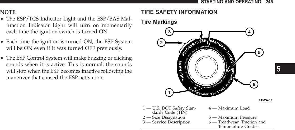
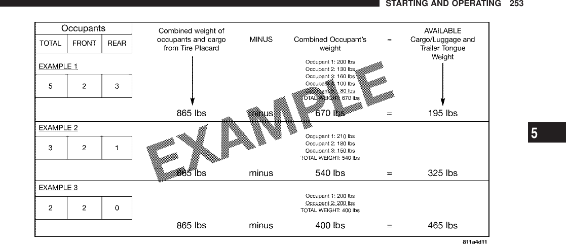
![LoadingThe vehicle maximum load on the tire must not exceedthe load carrying capacity of the tire on your vehicle. Youwill not exceed the tire’s load carrying capacity if youadhere to the loading conditions, tire size, and cold tireinflation pressures specified on the Tire and LoadingInformation placard and in the “Vehicle Loading” sectionof this manual.NOTE: Under a maximum loaded vehicle condition,gross axle weight ratings (GAWRs) for the front and rearaxles must not be exceeded. For further information onGAWRs, vehicle loading, and trailer towing, refer to“Vehicle Loading” in this section.To determine the maximum loading conditions of yourvehicle, locate the statement “The combined weight ofoccupants and cargo should never exceed XXX kg or XXXlbs.” on the Tire and Loading Information placard. Thecombined weight of occupants, cargo/luggage andtrailer tongue weight (if applicable) should never exceedthe weight referenced here.Steps for Determining Correct Load Limit1. Locate the statement “The combined weight of occu-pants and cargo should never exceed XXX kg or XXX lbs”on your vehicle’s placard.2. Determine the combined weight of the driver andpassengers that will be riding in your vehicle.3. Subtract the combined weight of the driver and pas-sengers from XXX kg or XXX lbs.4. The resulting figure equals the available amount ofcargo and luggage load capacity. For example, if “XXX”amount equals 1,400 lbs (635 kg) and there will be five150 lb (68 kg) passengers in your vehicle, the amount ofavailable cargo and luggage load capacity is 650 lbs (295kg) (since 5 x 150 = 750, and 1400 – 750 = 650 lbs [295 kg]).STARTING AND OPERATING 2515](https://usermanual.wiki/Marquardt/C01B/User-Guide-1046980-Page-253.png)
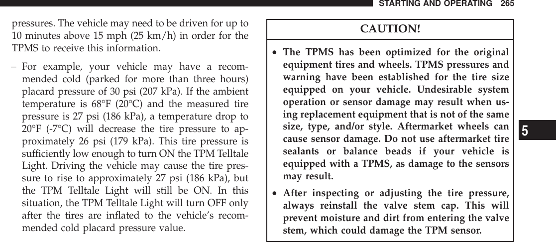
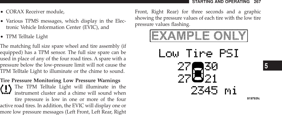
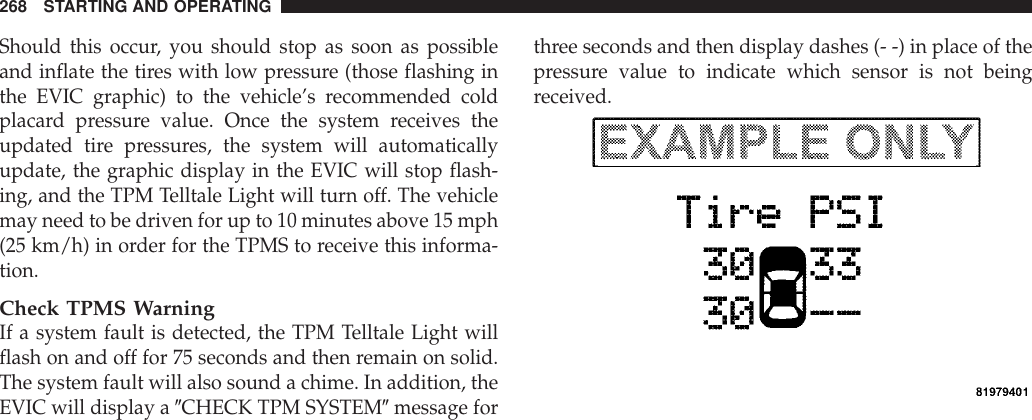
![TIRE PRESSURE MONITOR SYSTEM (TPMS)•The Tire Pressure Monitor System (TPMS) will warnthe driver of a low tire pressure based on the vehiclerecommended cold placard pressure.•The tire pressure will vary with temperature by about1 psi (6.9 kPa) for every 12°F (6.5°C). This means thatwhen the outside temperature decreases, the tire pres-sure will decrease. Tire pressure should always be setbased on cold inflation tire pressure. This is defined asthe tire pressure after the vehicle has not been drivenfor at least three hours, or driven less than 1 mi (1 km)after a three hour period. The cold tire inflationpressure must not exceed the maximum inflationpressure molded into the tire sidewall. Refer to “Tires– General Information” in this section for informationon how to properly inflate the vehicle’s tires. The tirepressure will also increase as the vehicle is driven - thisis normal and there should be no adjustment for thisincreased pressure.•The TPMS will warn the driver of a low tire pressureif the tire pressure falls below the low-pressure warn-ing limit for any reason, including low temperatureeffects and natural pressure loss through the tire.•The TPMS will continue to warn the driver of low tirepressure as long as the condition exists, and will notturn off until the tire pressure is at or above therecommended cold placard pressure. Once the low tirepressure warning (Tire Pressure Monitoring [TPM]Telltale Light) illuminates, you must increase the tirepressure to the recommended cold placard pressure inorder for the TPM Telltale Light to turn off. The systemwill automatically update and the TPM Telltale Lightwill turn off once the system receives the updated tire264 STARTING AND OPERATING](https://usermanual.wiki/Marquardt/C01B/User-Guide-1046980-Page-266.png)

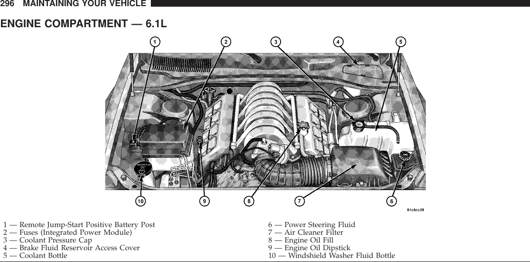
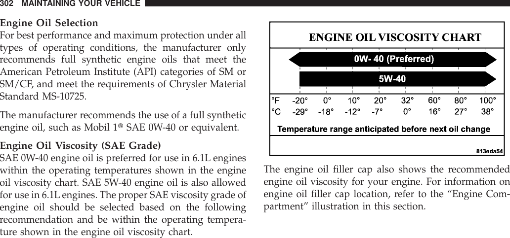
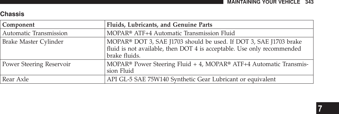
![FLUIDS, LUBRICANTS, AND GENUINE PARTSEngineComponent Fluids, Lubricants, and Genuine PartsEngine Coolant MOPARtAntifreeze/Coolant 5 Year/100,000 Mile Formula HOAT (HybridOrganic Additive Technology) or equivalentEngine Oil (6.1L) For best performance and maximum protection under all types of operatingconditions, the manufacturer only recommends full synthetic engine oils thatmeet the American Petroleum Institute (API) categories of SM or SM/CF, andmeet the requirements of Chrysler Material Standard MS-10725. The manu-facturer recommends the use of a full synthetic engine oil, such as Mobil 1tSAE 0W-40 or equivalent. For additional information, refer to the “Engine OilSelection” and “Engine Oil Viscosity (SAE Grade)” in the “Maintenance Pro-cedures” section of this manual.Oil Filter (6.1L) MOPARt05281090 or equivalentSpark Plugs (6.1L) PLZTR5A-13 (Gap.050 in [1.27 mm])Fuel Selection (6.1L) Premium Unleaded 91 Octane Only or higher342 MAINTAINING YOUR VEHICLE](https://usermanual.wiki/Marquardt/C01B/User-Guide-1046980-Page-344.png)