Marshall 1923 Users Manual
1923C to the manual e6749125-1cc0-4272-b5f0-f31972fc0992
2015-02-03
: Marshall Marshall-1923-Users-Manual-469095 marshall-1923-users-manual-469095 marshall pdf
Open the PDF directly: View PDF ![]() .
.
Page Count: 4


1
From the Chairman
Congratulations on your purchase of this very special Marshall
amplifier – the 1923.
Firstly, I must say that I feel very honoured that the team at
Marshall have created this amplifier to commemorate my 85th
birthday. I am simply thrilled with the design, the quality of
craftsmanship and of course the way it sounds – big, bold and
brimming full of Marshall tone.
Throughout my 85 years and in particular my past five decades in
the amplifier business, I have witnessed many changes in the
world of music. I have seen trends come and go, whole new
genres created and old ones revived. But whatever the musical
style of the last 46 years there has always been a Marshall amp to
suit – and there’s a good reason for this. When I made the first
Marshall amplifier in the early 1960s it was built to satisfy the
demands from guitarists for a ‘bigger sound’. I’m pleased to say
that this ethos of listening to the requirements and aspirations of
guitarists is as important today as it has ever been, remaining an
integral part of our continuing amplifier development.
I would like to thank the whole Marshall team for marking my 85th
year in such a poignant way and extend my gratitude to all
Marshall staff, past and present, for their hard work, skill and
craftsmanship. I have been privileged to have met many talented
musicians over the years, some of whom have become close
friends, and to them I would like to extend my gratitude for their
inspiration and friendship. I would also like to thank my family for
the years of love and support they have shown me, and last, but
by no means least, you the guitarist . . . it’s your passion for music
that drives me and the Marshall team to carry on creating new
innovative amplifiers and speaker cabinets.
I sincerely hope that this Limited Special Edition 1923 brings you
countless hours of playing pleasure and I would like to welcome
you to the ever increasing Marshall family.
Yours Sincerely
Dr. Jim Marshall OBE
ENGLISH
32
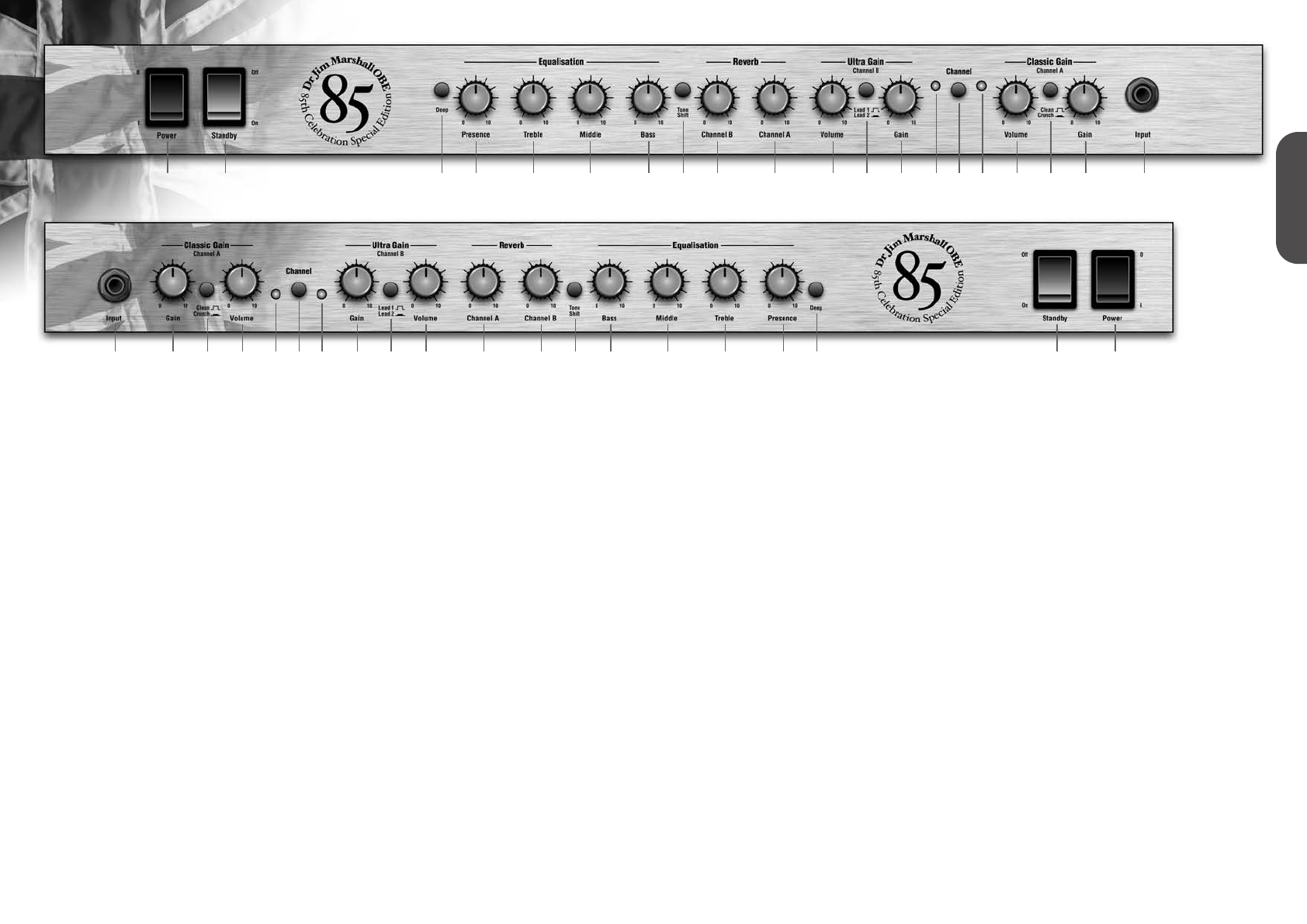
1. Power Switch
This is the On/Off switch for the mains electric
power to the amplifier.
Note: Please ensure the amplifier is switched off
and unplugged from the mains electricity supply
whenever it is moved!
2. Standby Switch
The Standby Switch is used in conjunction with
the Power Switch (1) to ‘warm up’ the amplifier
before use and to prolong the life of the valves.
When powering up the amplifier always engage
the Power Switch (1) first, leaving the Standby
switch in the ‘OFF’ position. This enables the
heater voltage, allowing the valves to come up
to their correct operating temperature. After
approximately two minutes the valves will have
reached their correct operating temperature and
the Standby Switch can be engaged, enabling
the HT. In order to prolong valve life, the
Standby Switch alone should also be used to
turn the amplifier on and off during breaks in a
performance. Also, when switching the amplifier
off, always disengage the Standby Switch prior
to the main Power Switch.
3. Deep Switch
The Deep Switch adds a tuned or resonant bass
boost to your sound, increasing bottom end
thud, without making your tone woolly around
the all important low end.
4. Presence Control
Adds higher frequencies to the guitar tone,
creating crispness and bite. Turning this up will
make the sound more cutting and in your face.
5.Treble Control
Controls the high frequencies of the guitar tone,
making your guitar sound brighter when
increased.
6. Middle Control
Dictates the middle register of the amplifier.
Turning this up will make your guitar sound
fatter. Conversely reducing the amount of middle
in your tone will result in a sharper and thinner
guitar sound for the classic “scooped” tone.
7. Bass Control
Controls the amount of low frequencies or
bottom end in your tone.
8.Tone Shift
The Tone Shift Switch reconfigures the tone
network components to give a new dimension to
passive tone shaping. With the switch selected
to the ‘in’ position and the Middle Control (item
6) turned down the result is a scooped mid
sound ideal for certain classic metal styles.
Reverb
9. Channel B
Controls the reverb level on Channel B.
10. Channel A
Controls the reverb level on Channel A.
Ultra Gain / Channel B
11. Volume
Governs the volume level of Channel B.
12. Lead 1 / Lead 2 Switch
The Channel B features two modes. The first,
Lead 1, gives an open high gain crunch, with
traditional Marshall characteristics, similar to a
hot-rodded JCM 800 2203 master volume. The
Lead 2 mode however gives a mid-boosted tone
coupled with even higher gain possibilities.
13. Gain
Controls the gain level for Channel B. As the
amount of gain increases so will the distortion
level in your sound.
14. LED
Indicates when Channel B has been selected.
15. Channel Switch
Selects Channel A or Channel B.
16. LED
Indicates when Channel A has been selected.
Classic Gain / Channel A
17. Volume
Governs the volume level of Channel A
18. Clean / Crunch
As with Channel B, Channel A features two
modes. The first, Clean, is reminiscent of an
early 1959 Plexi Super Lead head. Depending
on Gain settings (item 19) this mode will take
you from clean to a controlled Plexi style crunch.
Crunch will take you up to a JCM 800 2203 style
grind.
19. Gain
Controls the gain level for Channel A. As the
amount of gain increases so will the distortion
level in your tone.
20. Input Jack Socket
This high impedance input is where you plug
your guitar into the amp. You must use a
screened (shielded) guitar cable. Never use an
unscreened (unshielded) speaker cable
because you will find it very noisy to the point of
annoyance. The input to any guitar amplifier is a
very sensitive part of the signal path and is
therefore susceptible to air born radio
interference, hence the need for a screened
guitar cable. This screened cable should
preferably be of good quality. If you are in any
doubt regarding this, your Marshall dealer will
be more than happy to help, advise and supply
you.
1
20 19 17 13 11 10 9 7 6 5 4 2 116 141518 12 8 3
2 3 4 5 6 7 9 10 11 13 17 19 208 12 1514 16 18
ENGLISH
ENGLISH
54
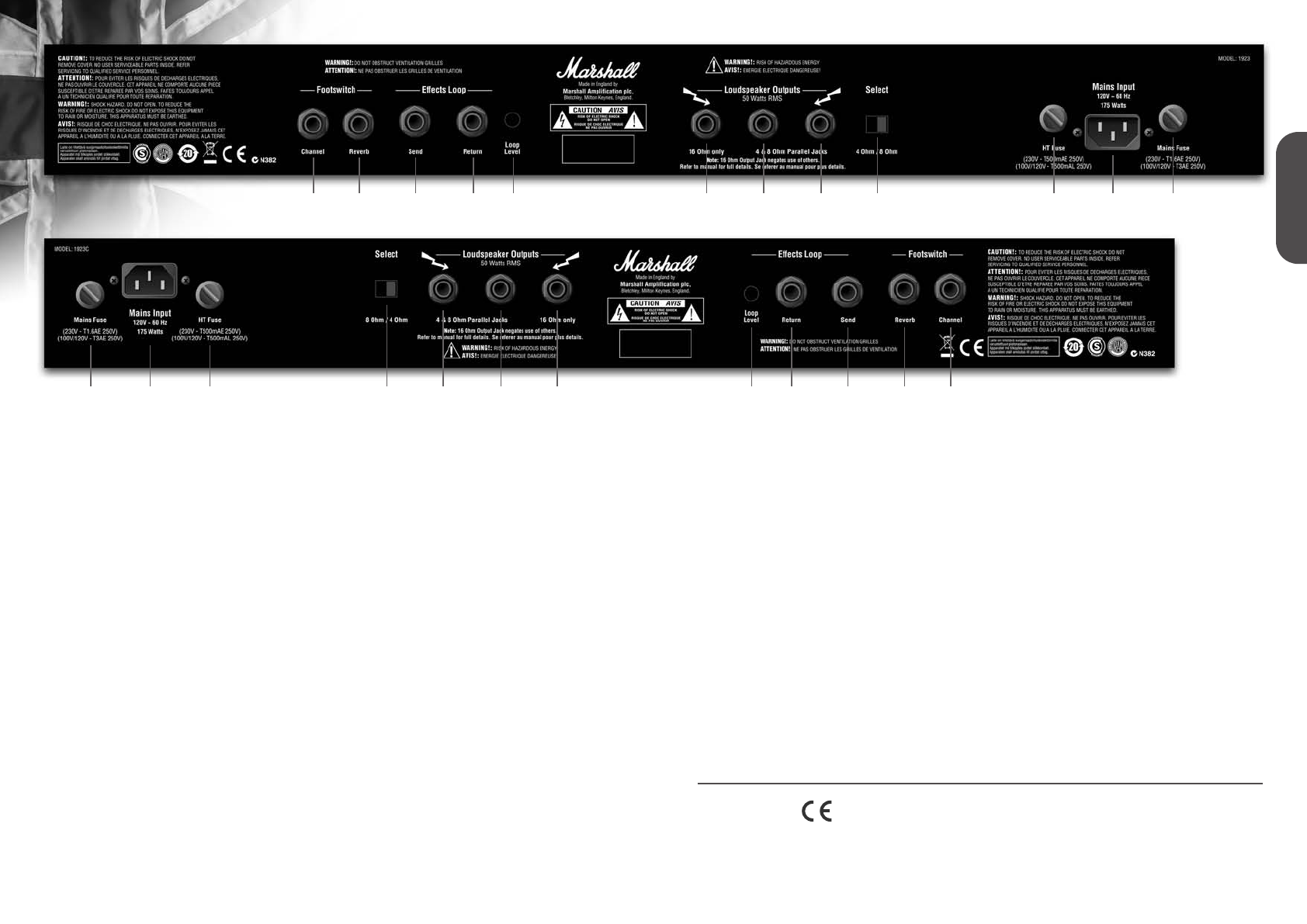
Footswitch
1. Channel
By connecting the supplied PEDL10001
footswitch to this jack it is possible to switch
between Channel A and Channel B. The
footswitch will override the front panel Channel
switch position (item 15).
2. Reverb Footswitch
By connecting another PEDL10001 footswitch
(optional) to this jack it is possible to remotely
switch reverb on and off.
Effects Loop
3. Send
For connection to the input of an external effects
processor.
4. Return
For connection from the output of an external
effects processor.
5. Loop Level
The loop level can be adjusted to match either
floor pedals, requiring a low level or effects
processors which require a high level.
Loudspeaker Outputs
With all valve amplifiers it is imperative that the
amp is connected to a load whilst in operation
and that the impedance selected on the amp
matches the total impedance of the speaker
cabinet(s) being used.
Failure to comply with these points will result in
damage to the amplifier.
The three outputs, a dedicated 16 Ohm output
and two outputs selectable between 4 and 8
Ohms.
The amp should not be run into an impedance
less than 4 Ohms.
6. 16 Ohm Output
For the connection of a 16 Ohm speaker
cabinet. It should be noted that when this
Speaker Output is in use the remaining Speaker
Outputs, items 7 and 8, will become
inoperational.
7 & 8. 4 & 8 Ohm Outputs
For use when the total impedance of speaker
cabinets used is either 4 or 8 Ohms. That is,
when using either a single 4 Ohm cab, a single
8 Ohm, two 8 Ohm cabs or two 16 Ohm cabs.
9. Impedance Selector
Allows selection of 4 or 8 Ohms impedance for
items 7 & 8. See Loading Points.
10. H.T. fuse
See rear panel for correct value.
11. Mains Input
Your amp is provided with a detachable mains
(power) lead which is connected here. The
specific mains input voltage rating that your
amplifier has been built for is shown on the back
panel. Before connecting for the first time,
please ensure that your amplifier is compatible
with your electricity supply. If you have any
doubt, please get advice from a qualified
person. Your Marshall dealer will help in this
respect.
12. Mains fuse
See rear panel for correct value.
Loading Points
One 4 Ohm cabinet, set to 4 Ohms
One 8 Ohm cabinet, set to 8 Ohms
Two 8 Ohm cabinets, set to 4 Ohms
Two 16 Ohm cabinets, set to 8 Ohms
N.B. Always ensure that proper speaker leads
are used to connect speakers, not guitar leads!
WARNING!
If loudspeaker is disconnected a high voltage
can be present at these output terminals.
Operation in this manner can damage your
amplifier, therefore ensure that loudspeaker is
properly connected.
Your amp should be completely powered down
before changing loads.
1
12 11 10 9 8 7 6 5 4 3 2 1
2 3 4 5 6 7 8 9 10 11 12
* EUROPE ONLY - Note: This equipment has been tested and found to comply with the
requirements of the EMC Directive (Environments E1, E2 and E3 EN 55103-1/2) and the Low Voltage
Directive in the E.U.
* EUROPE ONLY - Note: The Peak Inrush current for the 1923 and 1923C is 33 amps.
Follow all instructions and heed all warnings
KEEP THESE INSTRUCTIONS !
