Marvell Semiconductor K402 IoT Development Kit User Manual Print
Marvell Semiconductor, Inc. IoT Development Kit Print
UserManual.wiki
>
Marvell Semiconductor
>
K402 User Manual
Users Manual
Navigation menu
Upload a User Manual
Namespaces
Wiki Guide
HTML
PDF
Info
Views
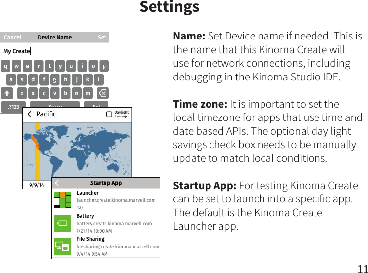
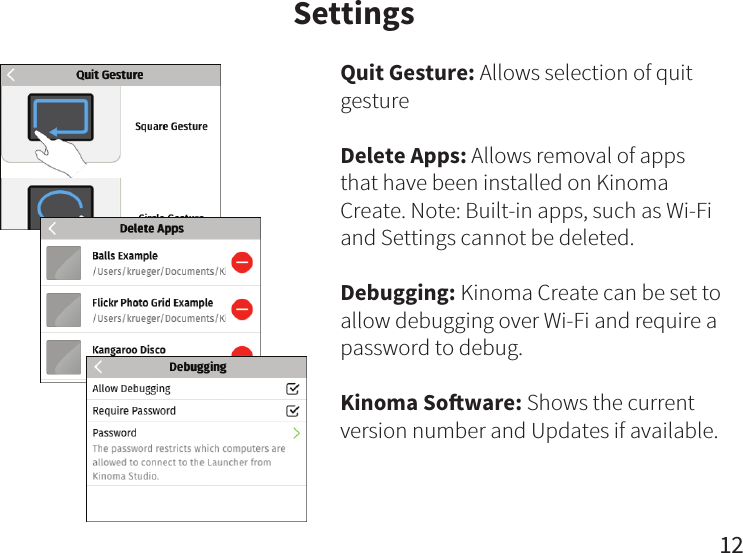
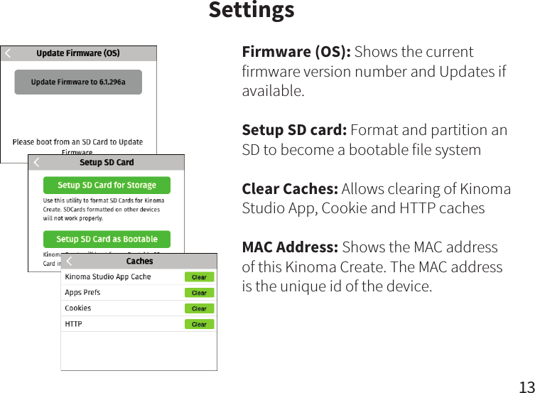
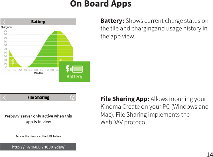
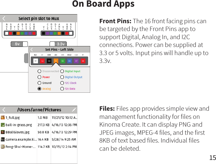
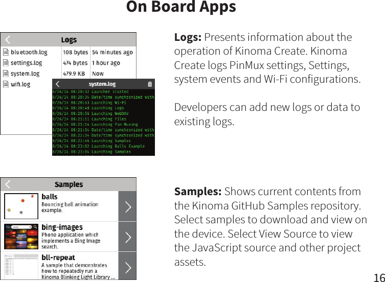
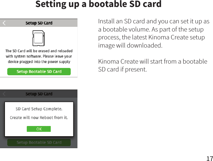
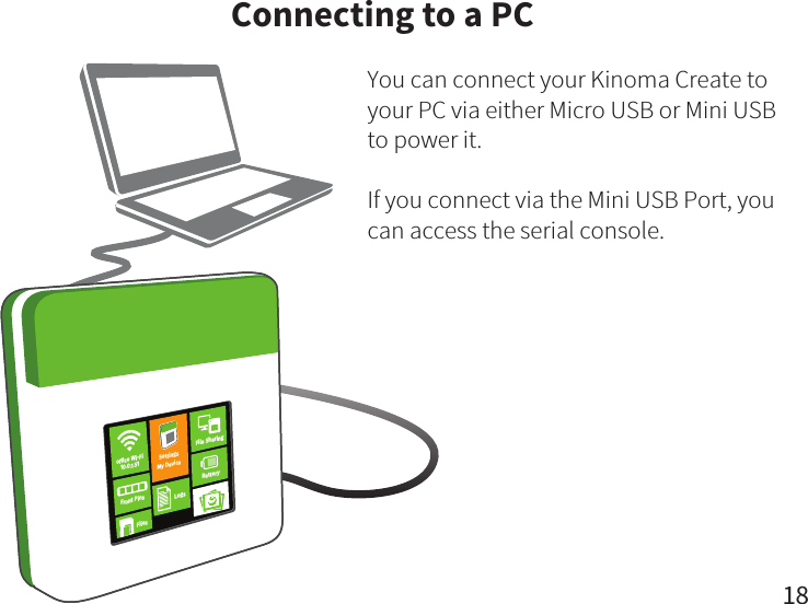
User Manual
Discussion / Help
Navigation