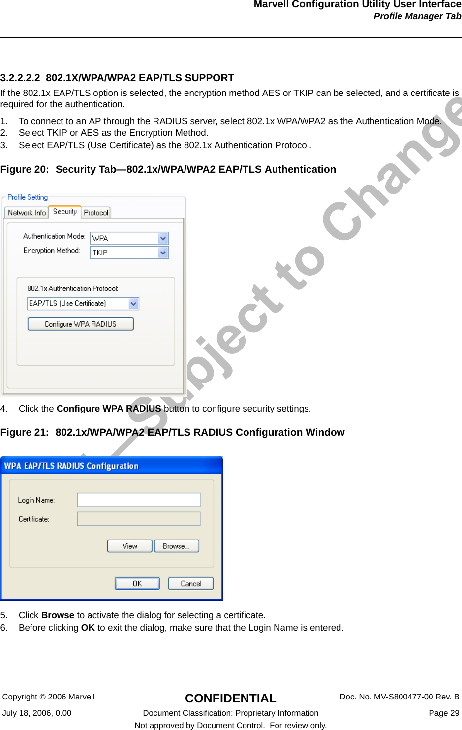
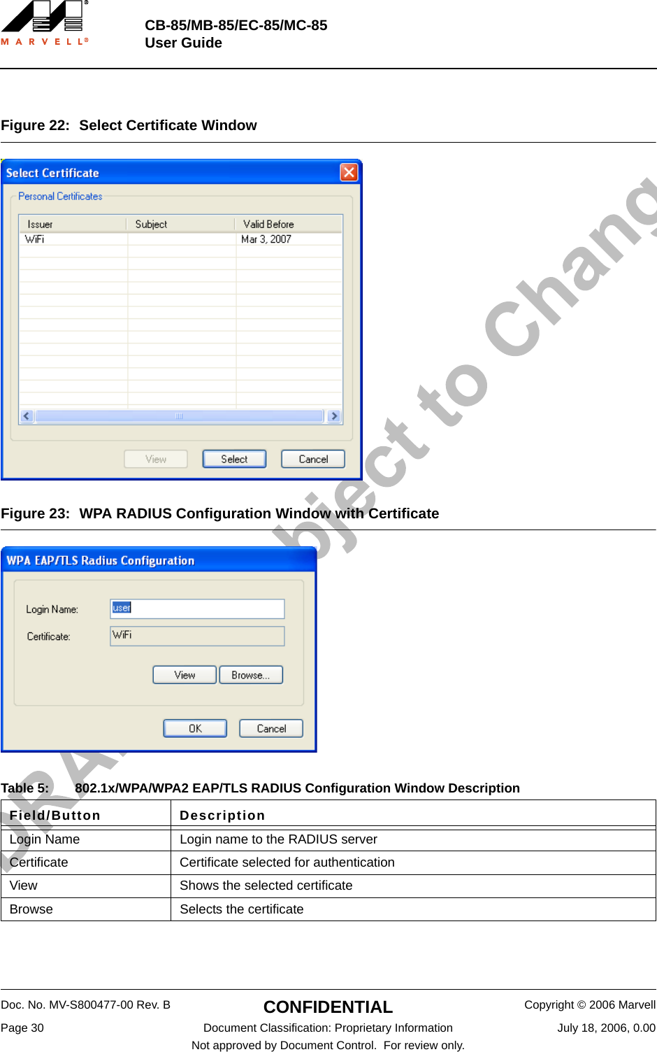
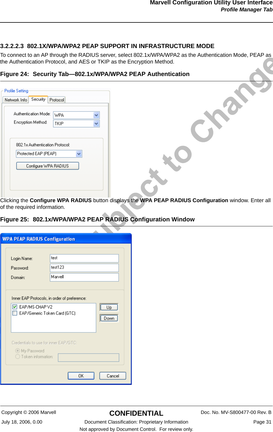
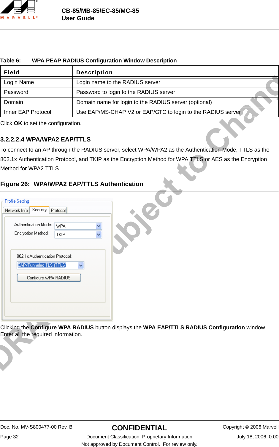
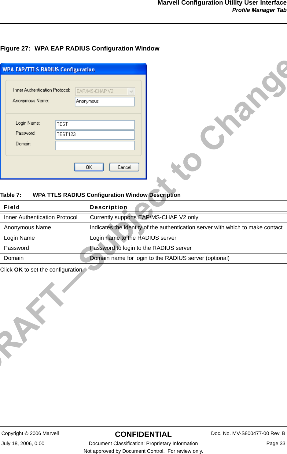
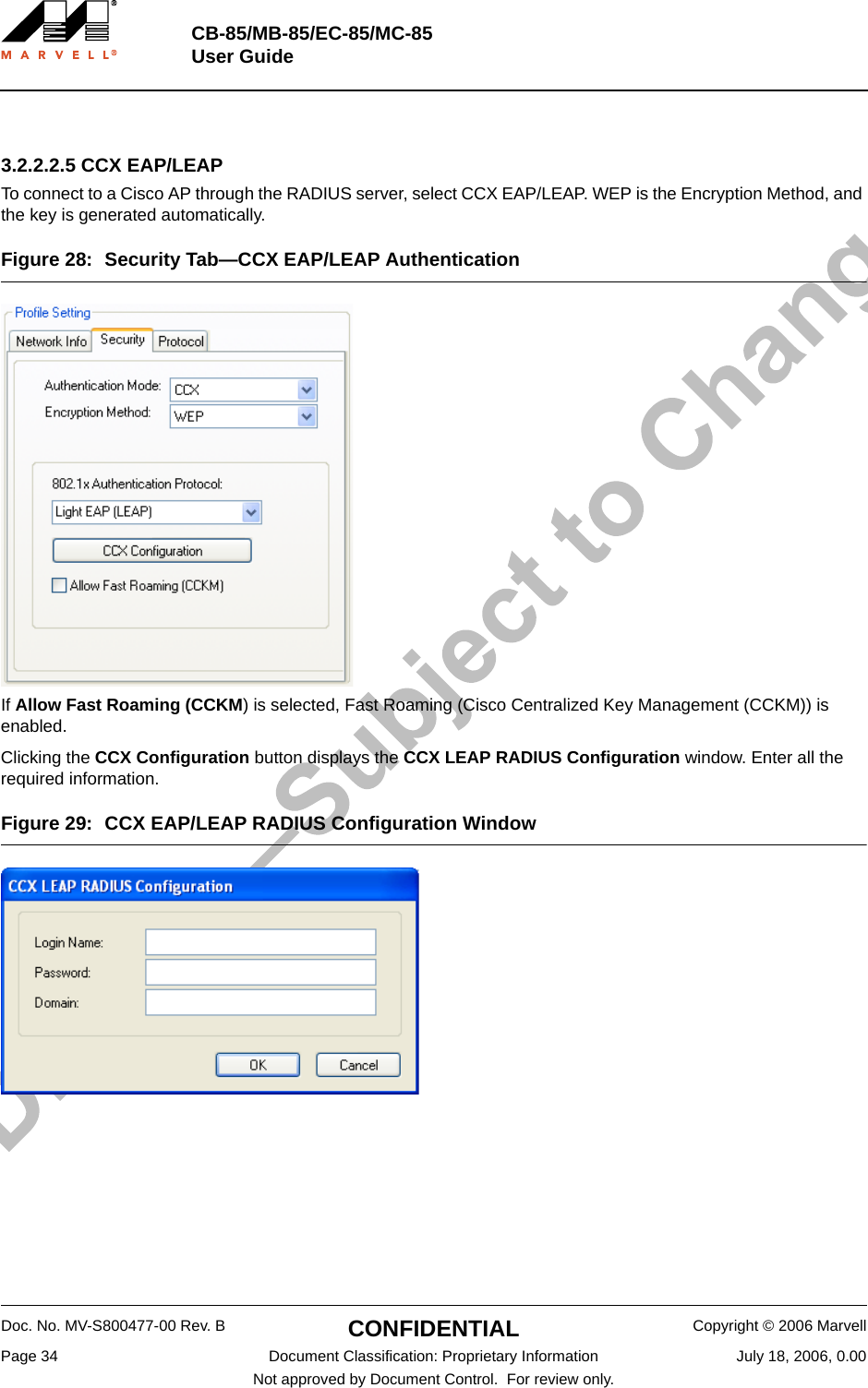
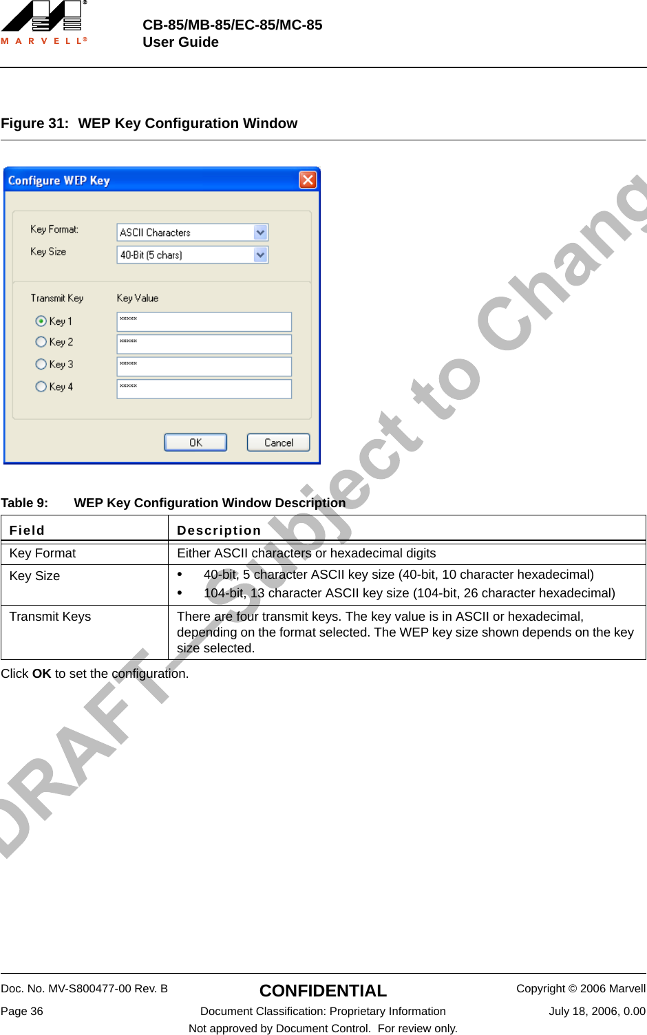
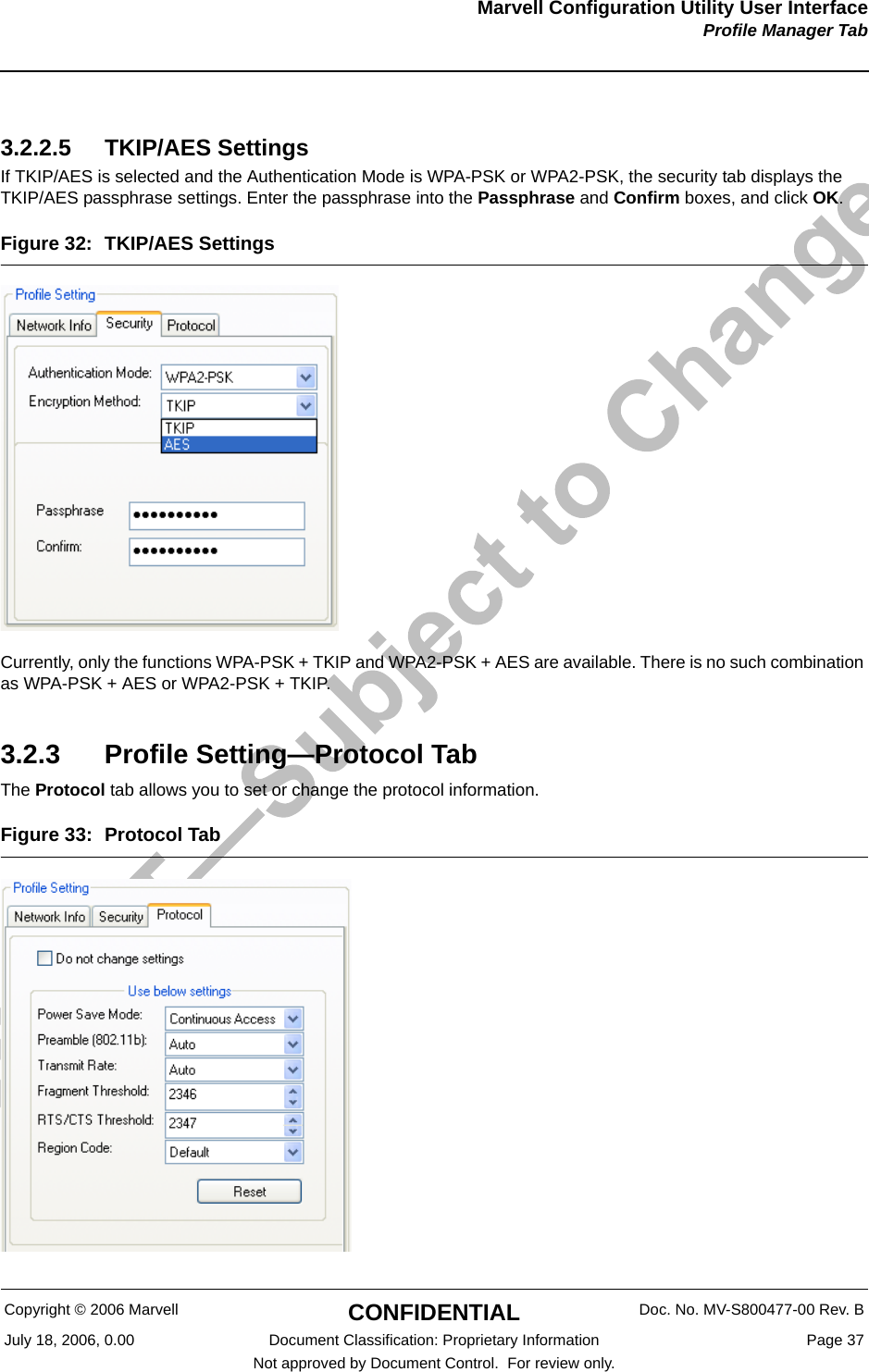
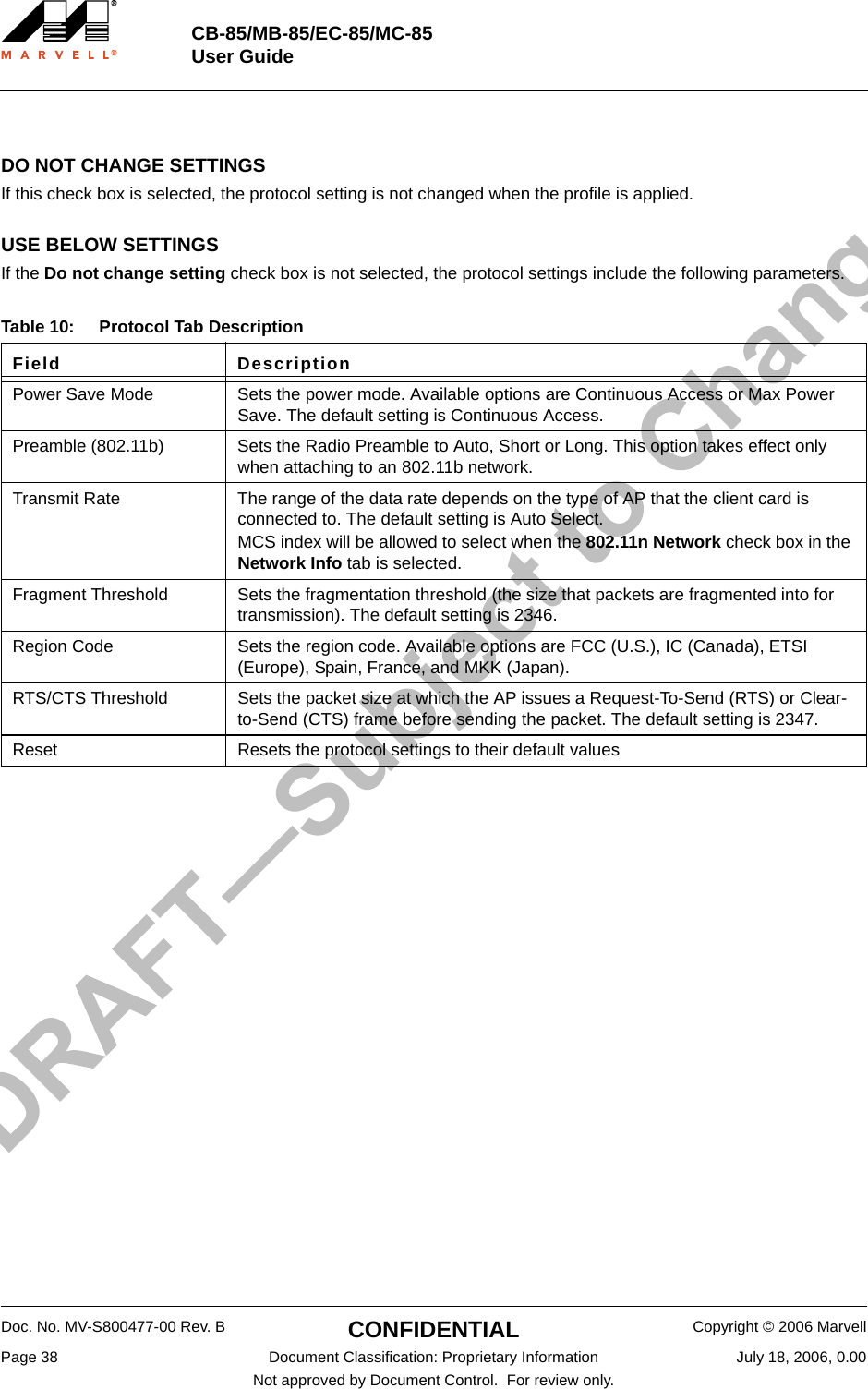
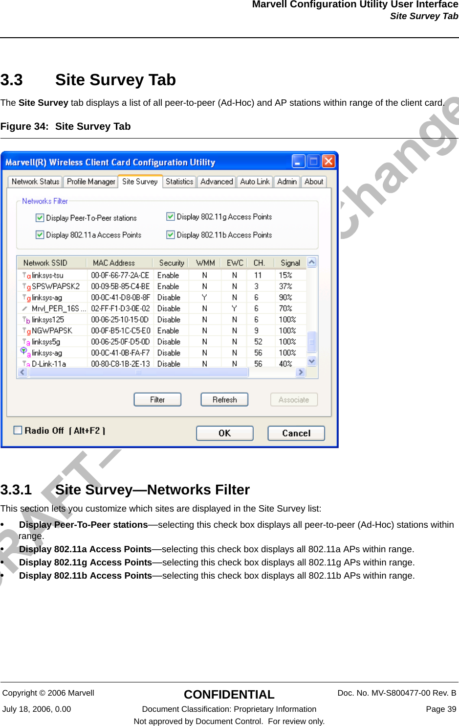
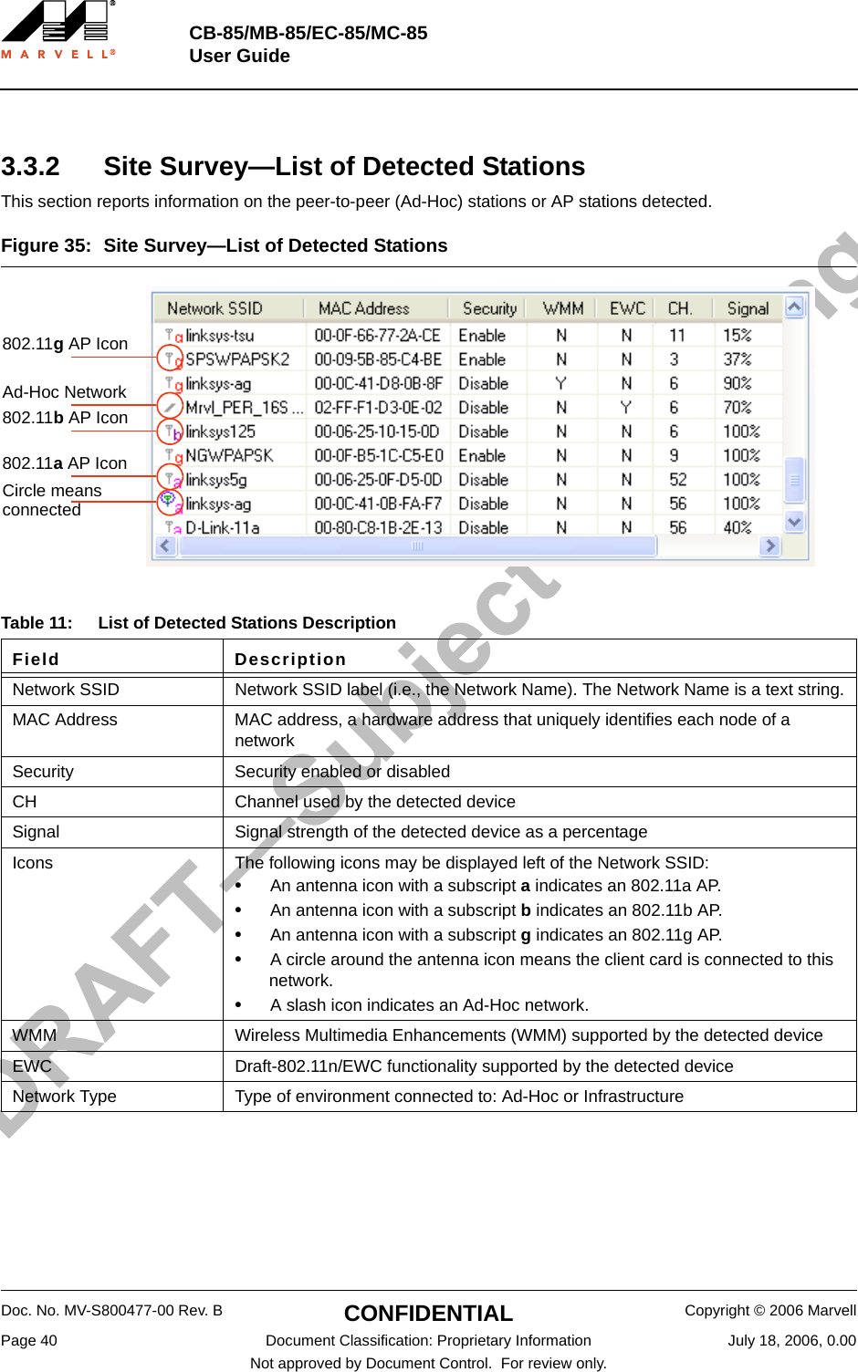
Marvell Semiconductor MMC85M MC85 Mini Card 11b/g/a/n Radio Card User Manual
Marvell Semiconductor, Inc. MC85 Mini Card 11b/g/a/n Radio Card
UserManual.wiki
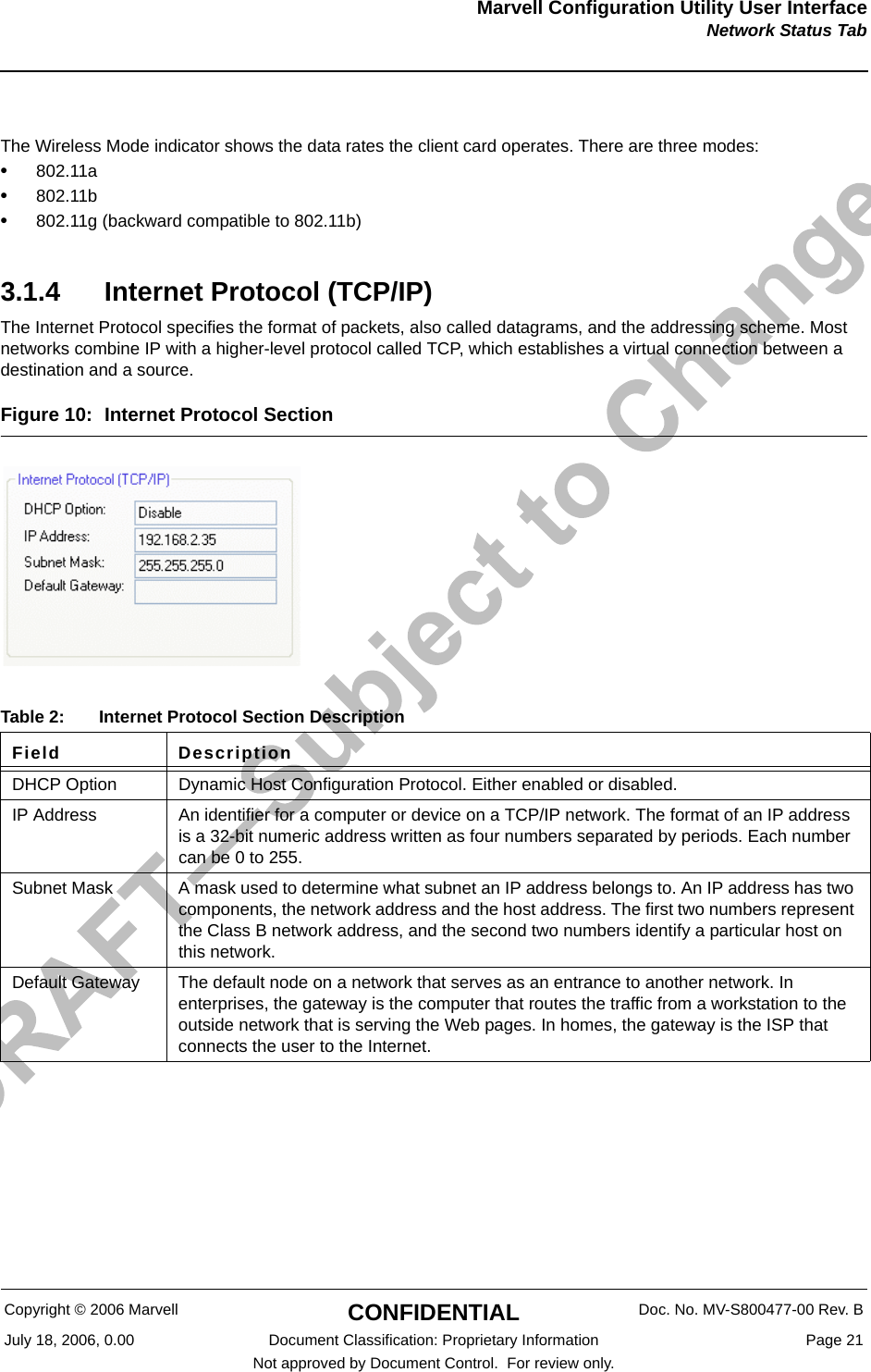
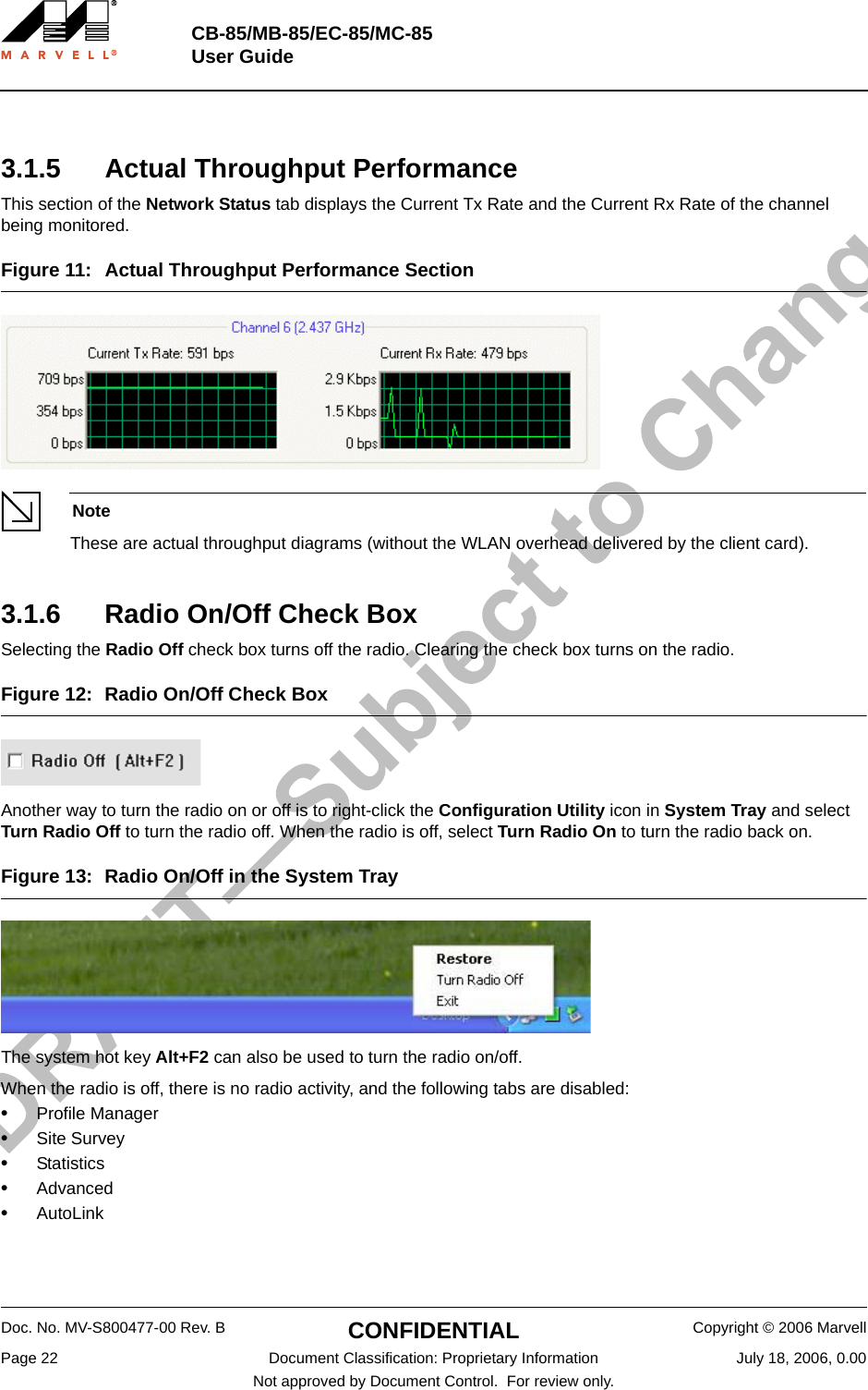
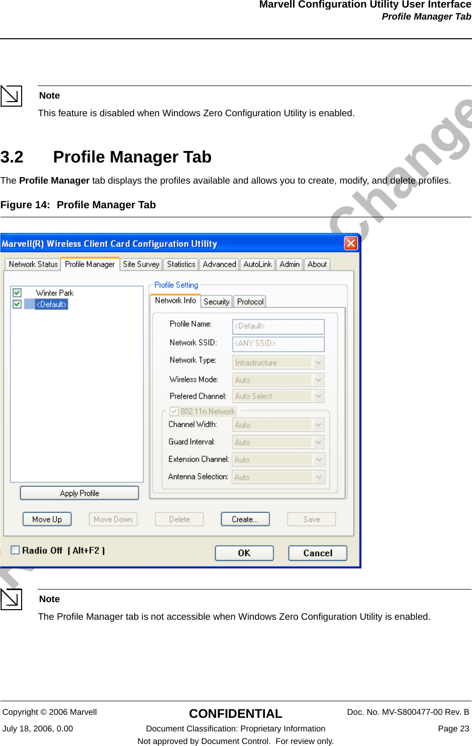
>
Marvell Semiconductor
>
MMC85M User Manual
>
User Manual
Contents
1.
User Manual
2.
USer Manual
3.
Users Manual
User Manual
Navigation menu
Upload a User Manual
Namespaces
Wiki Guide
HTML
PDF
Info
Views
User Manual
Discussion / Help
Navigation