Marvelmind Robotics 915MHZM Modem 915MHz v4.95 User Manual Marvelmind Indoor Navigation System manual
Marvelmind Robotics Modem 915MHz v4.95 Marvelmind Indoor Navigation System manual
UserManual.wiki
>
Marvelmind Robotics
>
915MHZM User Manual
>
User Manual
Contents
1.
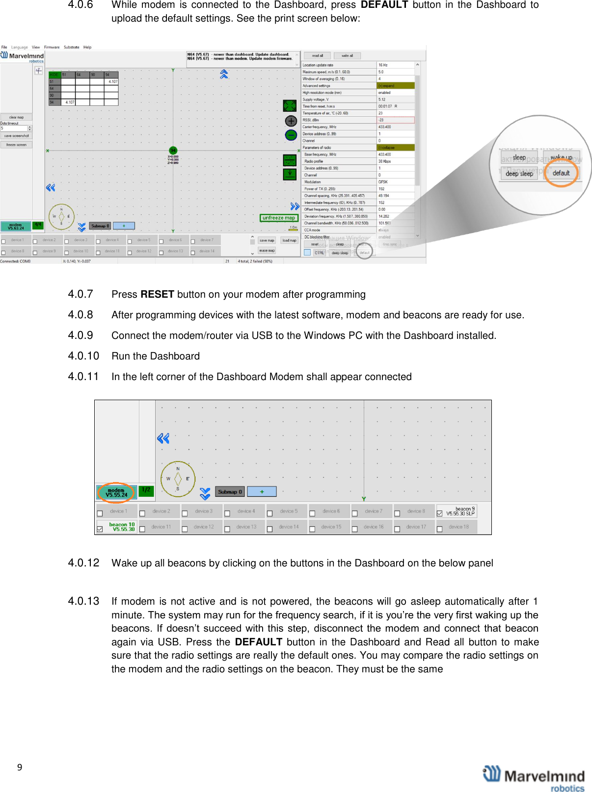
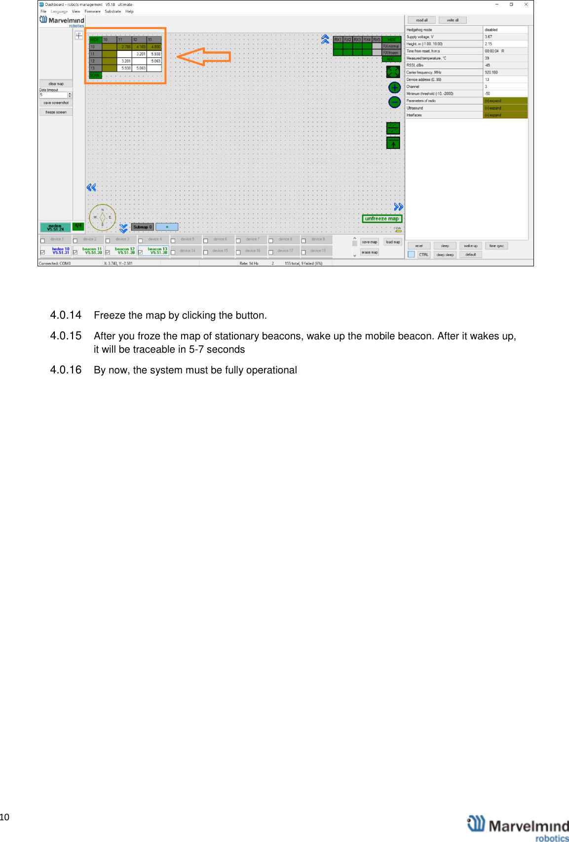
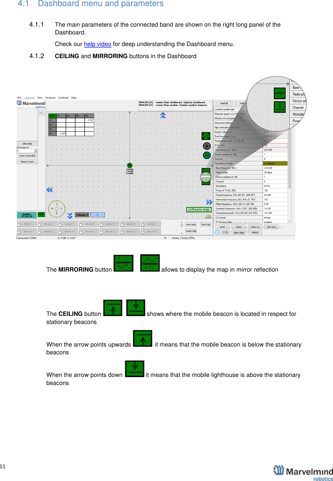
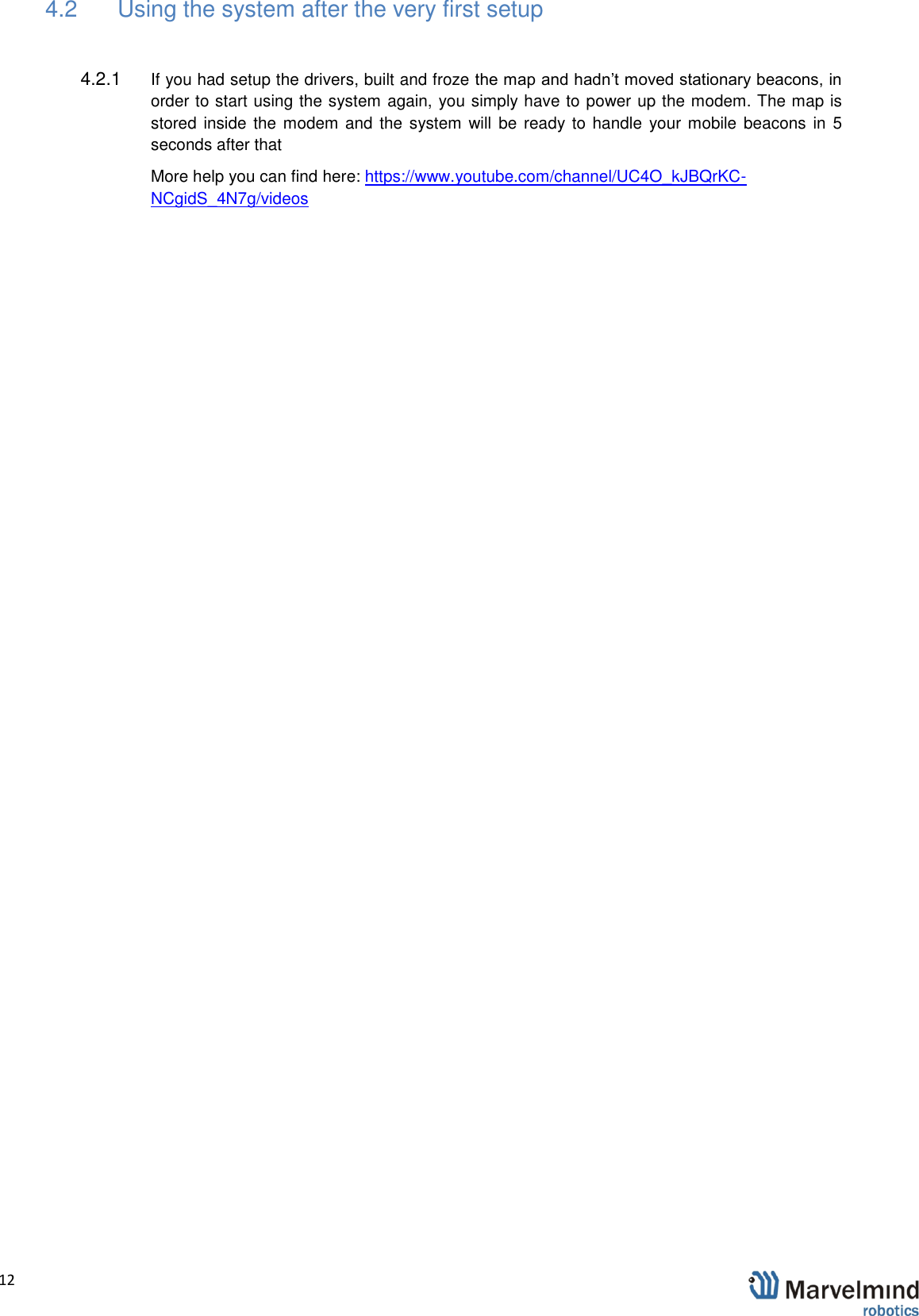
User Manual
2.
Users Manual
User Manual
Navigation menu
Upload a User Manual
Namespaces
Wiki Guide
HTML
PDF
Info
Views
User Manual
Discussion / Help
Navigation