Mascot Electric IEM-168 UHF Transmitter User Manual IEM168menu
Mascot Electric Co., Ltd. UHF Transmitter IEM168menu
Users Manual
RF LEVE L
RF LEVEL
DIVERSITY
AF
OPEN
OPEN
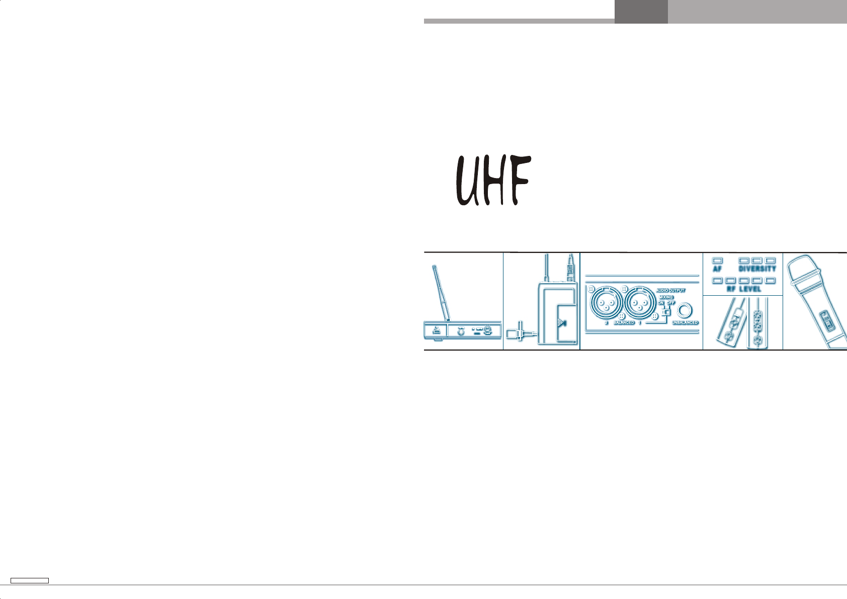
U H F
P LL S Y N T H E S I Z E D
IN-EAR MONITOR SYSTEM
USER'S MANUAL
440-0 168-0
BAND DIVERSITY
PRODUCT DESCRIPTION
INTRODUCTION
12
Wireless Wireless
1
23
3
456789
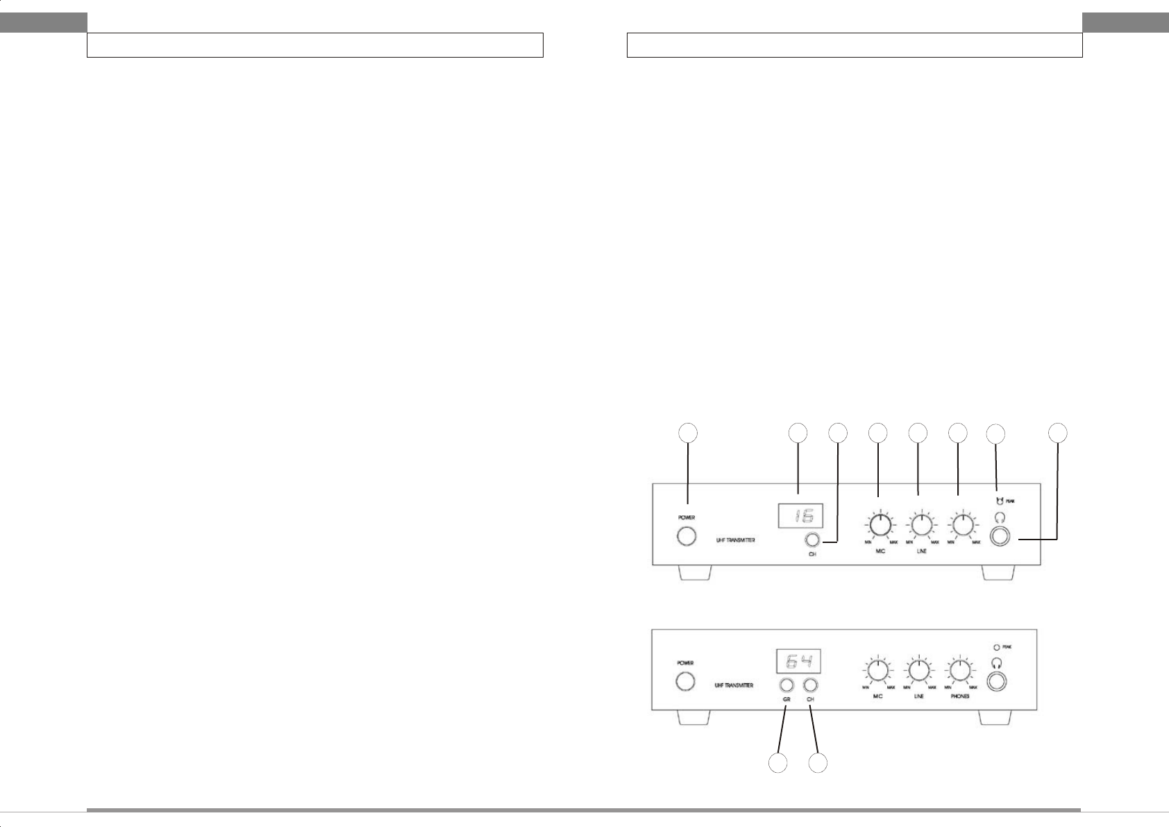
Fig.1 16 channels model
Fro nt pa nel
Fig.2 64 channels model
Fro nt pa nel
1. Introduction
Thank you for purchasing our product. This in-ear monitor system operates in
UHF band frequency with Phase Locked Loop (PLL) synthesizer controlled. The
system with 16 or 64 selectable frequencies via PLL circuitry makes it easy to
choose non-interfered channels. Please read this instruction manual carefully before
operating the system. This manual covers the function and operation of the in-ear
monitor system.
2. Safety
Do not spill liquid on the appliance and do not drop it on a hard surface.
Do not place the appliance near heat sources, such as radiators, amplifier, etc..
Do not expose it directly to sunlight, extremely dust, excessive moisture, or
vibration.
Unplug the power if the appliance has been not used for a long period. This
will avoid the damage resulted by surge electricity.
3. Feature
IEM-168 is a Low-Power FM broadcasting transmitter. At the same time, it can
send out stereo music (work with CD player, MP3, etc.) and vocal
broadcasting (works with wired or wireless microphone system).
There are up to 16 or 64 selectable channels to set up a multi-channels
broadcasting system and to avoid the frequency inference. Also, the LED
displayer gives us a clear channel indication. And, user can select channels or
groups easily by using rotary switch.
The stereo audio signal (works with CD player, MP3, etc.) can be input easily
through the RCA jack.
The wired microphone can be connected to the 6.3Φ jack or to the XLR
connector.
The Peak LED indicator can help avoiding the audio distortion.
User can plug a headphone into the headphone jack on the front panel to
monitor the sending out audio signal.
IEM-168’s antenna is a high efficiency antenna. The service area can be
improved when the antenna is placed at higher location.
IEM-168 can combine with a RF power booster (AB-168, which is 1Watt max)
to used for an over 1 km area service.
4. Product Description
1. Power: push bottom to power on and push again to power off.
2. Group Rotary: adjust rotary to select frequency group.
3. Channel Rotary: adjust rotary to select frequency channel.
4. Channels LED display: indicate the current channel number. The number
would show up when the power is on.
5. MIC Volume Control: adjust the volume of MIC input level.
6. Line Volume Control: adjust the volume of Line In input level.
7. Monitoring Headphone Volume Control: adjust the volume of monitoring
headphone.
8. Peak Indicator: indicate the input audio signal is too high and may cause
distortion.
9. Headphone Jack: 6.3Φ headphone jack stereo type.
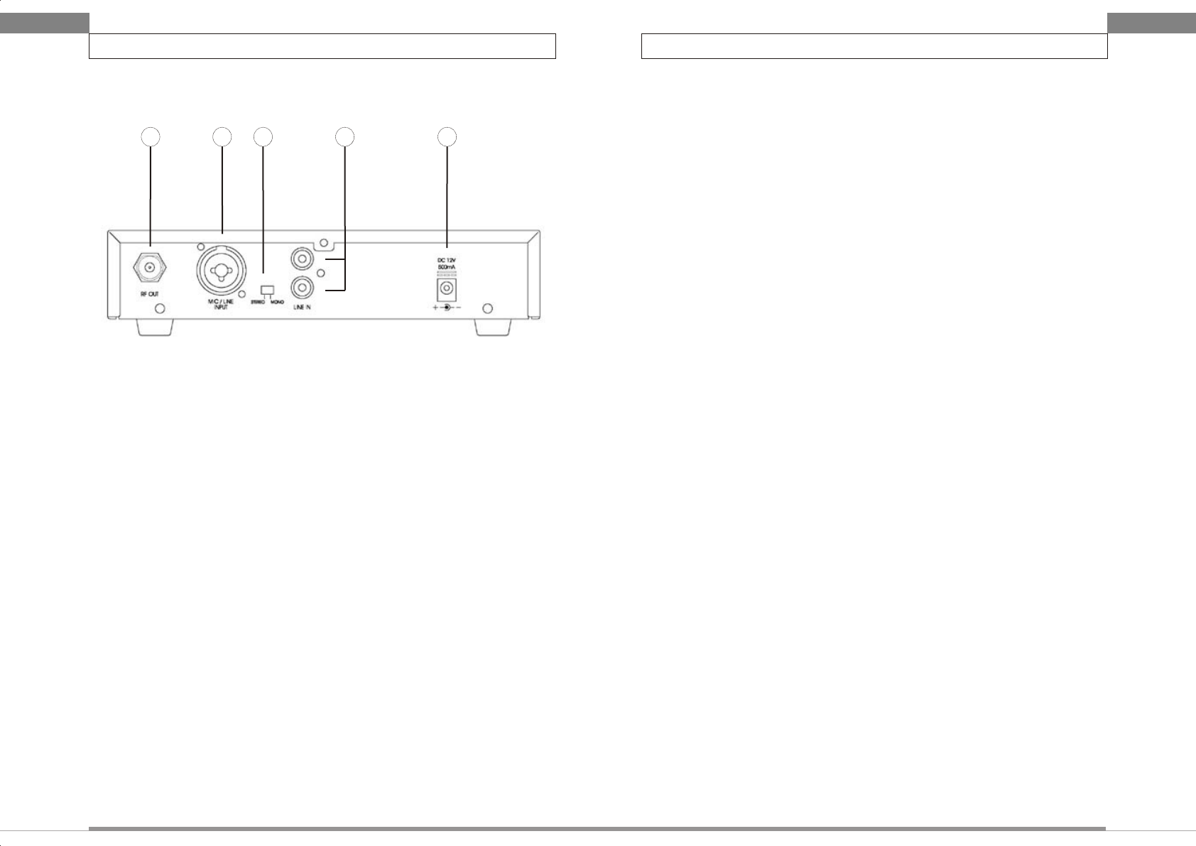
10. Antenna Socket: TNC socket for antenna.
11. MIC IN: 6.3Φ / XLR jack for wired microphone.
12. Stereo/Mono Switch: switch the stereo or mono mode of audio signal.
13. Line IN: RCA jack for stereo audio input.
14. DC Power Jack: DC input connector for the supplied AC adapter.
SETTING-UP
3
Wireless Wireless
SETTING-UP
4
10 1 1 12 13 14
5.2 Setting up the transmitter
Connect 6.3Φ plug or XLR plug of the wired microphone in MIC IN jack on
the transmitter rear panel. Turn the MIC Volume Control on the transmitter
clockwise to set the transmitter input to receiver level.
Use the RCA plug to connect the Audio In jack on the transmitter rear panel.
Turn the Line Volume control on the transmitter clockwise to set the
transmitter input to receiver level.
For monitoring purpose, plug the headphone into the monitoring headphone
jack on the front panel of transmitter. Turn the Monitoring Headphone Volume
on the transmitter clockwise to set the headphone volume.
5.3 Setting up the frequency
For 16 channels model, adjust channel rotary to select channel to set up
frequency.
For 64 channels model, frequency is divided into 8 groups, which there are 8
channels in each group. Adjust group rotary to setup group number. Adjust
channel rotary to setup channel number.
Fi g.3 r ear p ane l
5. Setting-Up
NOTICE: Prior to setting up, please make sure the microphone and the
receiver are turned to the same frequency. Two or above wireless
microphones operating in the same frequency can not be used at the same
time and area. So please select the different frequencies which cam be used
simultaneously at the same area.
5.1 Connecting the transmitter to power
Attach the UHF antenna to the TNC connector on the rear panel.
Please check the voltage of the supplied AC adapter conforms to the voltage
available in local area. Using the wrong AC adapter may cause irreparable
damage to the unit.
Plug the feeder cable of the supplied AC adapter into DC IN socket on the
transmitter. Then plug the AC adapter into a power outlet.
THIS DEVICE COMPLIES WITH PART 15 OF THE FCC RULES. OPERATION IS SUBJECT
TO THE FOLLOWING TWO CONDITIONS: (1) THIS DEVICE MAY NOT CAUSE HARMFUL
INTERFERENCE AND (2) THIS DEVICE MUST ACCEPT ANY INTERFERENCE RECEIVED,
INCLUDING INTERFERENCE THAT MAY CAUSE UNDESIRED OPERATION.
Notice : The changes or modifications not expressly approved by the party responsible
for compliance could void the user’s authority to operate the equipment.
IMPORTANT NOTE: To comply with the FCC RF exposure compliance requirements, no
change to the antenna or the device is permitted. Any change to the antenna or the device
could result in the device exceeding the RF exposure requirements and void user’s
authority to operate the device.
SPECIFICATION
TROUBLE-SHOOTING
56
Wireless Wireless
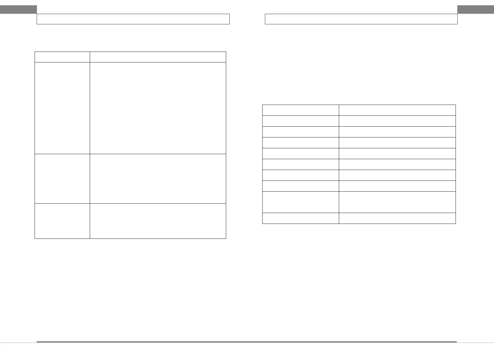
6. Trouble-shooting
Problem Solution
No sound Check the power supply of the
transmitter and receiver.
Check that the transmitter and receiver
are turned to the same frequency.
Check whether the Hi-Fi appliance is
switched on and the transmitter output is
connected to mixer or amplifier input.
Check whether receiver is too far away
from transmitter.
Check whether transmitter is located too
near metal object or there are
obstructions between transmitter and
receiver.
Sound
interference
Check the antenna location.
When using 2 or above transmitters
simultaneously, make sure that the
chosen frequencies are not interfered.
Check whether the interference comes
from other wireless microphone, TV,
radio and etc..
Distortion Check the volume control for transmitter
is adjusted too high or too low.
Check whether the interference comes
from other wireless microphone, TV,
radio and etc..
7. Environment
When disposing the equipment, remove the screws, separate the case, circuit
boards, and cables, and dispose of all components according to local waste
disposal rules.
8. System Specification
Frequency range UHF 630 ~ 806MHz
RF power output 10mW or 100mW
Frequency stability ±0.005%
Maximum deviation ±48KHz with limiting compressor
Spurious emission >60dB below carrier frequency
T.H.D. <1% (at 1KHz)
Power supply DC12 ~18V
Tone key 32.768 KHz
Current consumption 85mA ±10mA(10mW) ; 140mA
±10mA(100mW)
Dimension(mm)WxHxD 211x44x180