Mascot Electric UF-18HE Wireless Microphone system User Manual 01
Mascot Electric Co., Ltd. Wireless Microphone system 01
Users Manual

- Connecting the Receiver
- Set up the Handheld Microphone / Bodypack transmitter
- Receiver
- Handheld Microphone
- Bodypack transmitter
- FCC Statement
- Safety
- Environment
z Product Description.................................................................. 2
z Introduction............................................................................. 1
z System Operation..................................................................... 6
z Trouble Shooting...................................................................... 8
z System Feature........................................................................ 8
z System Specification............................................................... 9

WIRELESS
INTRODUCTION
FCC Statement
This device complies with part 15 of the FCC rules. Operation is subject to the following two
conditions: (1)This device may not cause harmful interference and (2) This device must
accept any interference received, including interference that may cause undesired operation
Notice : The changes or modifications not expressly approved by the party responsible for
compliance could void the user’s authority to operate the equipment.
IMPORTANT NOTE: To comply with the FCC RF exposure compliance requirements, no
change to the antenna or the device is permitted. Any change to the antenna or the device
could result in the device exceeding the RF exposure requirements and void user’s authority
to operate the device.
zIntroduction
Thank you for purchasing our product. This PLL synthesized wireless microphone system
operates in UHF band frequency with 16 selectable channels. Please read this instruction
manual carefully before operating the system. This manual covers the function and
operation of the wireless microphone system.
Safety
¾Do not spill liquid on the appliance and do not drop it on a hard concrete floor.
¾Do not place the equipment near heat sources such as radiators, heating ducts, amplifier, etc.
¾If the equipment is not going to be used for a long time, disconnect the AC adapter from
the power outlet. Please note that if you turn the equipment off while leaving the AC
adapter plugged in, it is not fully isolated from the power supply.
¾Do not expose the equipment to direct sunlight, extremely dust, excessive moisture, rain,
mechanical vibrations, or shock.
¾Take out the battery from transmitter, if the appliance has been not used for a longer period.
This will avoid the damage resulting from a defective leaking battery.
¾WARNING: To reduce the risk of fire or electric shock, do not use the products near water
and do not expose them to rain or moisture.
¾No guarantee claims for the equipment and no liability for any resulting personal damage
or material damage will be accepted if the equipment are used for other purpose than
originally intended, if the equipment are not correctly connected or operated, or if the
equipment are not repaired in an expert way.
Environment
¾Do not throw used batteries into a fire or garbage bin with domestic rubbish. Be sure to
dispose of used batteries in accordance with local waste disposal rules.
¾When disposing the equipment, remove the batteries, separate the case, circuit boards,
and cables, and dispose of all components in accordance with local waste disposal rules.
1
WIRELESS PRODUCT DESCRIPTION
z
Product Description
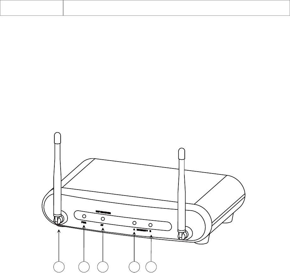
¾ Receivers
The receivers are used with our 16-channel selectable channels transmitters. (The
number of frequency channels depends on local regulations.) The receiver operates in UHF
band frequency with PLL synthesized control. Powered by 12V DC. !
¾ Single Channel
Switching Diversity, Front Fixed Antenna
1 2 3 44
1.Antenna
2.Power Indicator: The LED lights up to show the receiver is ready to operate.
3.AF Indicator: The LED lights up to show the reception of AF signal.
4.Diversity A/B Indicator: The LED lights up to show the reception of RF signal.
2
WIRELESS
PRODUCT DESCRIPTION
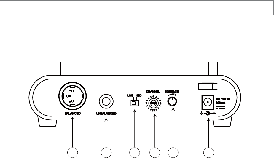
1. Balanced XLR Audio Output
2. Unbalance 6.35mm Audio Output
3. MIC/LINE Switch: Use this to adjust the audio output level for MIC level (-20dB) or
LINE level (0dB).
4. Squelch: Turn the switch to adjust or decrease the noise floor level.
5. Power Adapter Connector
1 2 3 4 5 6
3
WIRELESS PRODUCT DESCRIPTION
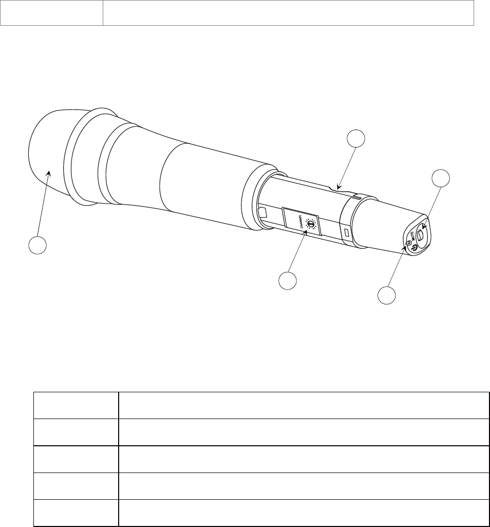
¾ Handheld Microphone
1. Grille: Protects the microphone capsule and helps reduce breath sounds and wind noise.
2. Power LED: Indicate the power / mute / low battery level status.
3. Power Button
4. Battery Compartment: Insert two AA dry or rechargeable batteries into the compartment
and make sure that the polarity of batteries is correct.
5. Channel Selector: Change the channel setting from 1 to 16.
4
1
5
3
4
2
LED Indicator Status
Red Ready
Flashing Red Low battery power when less than 10 minutes operation
Blue MUTE
Flashing Blue MUTE on and low battery power when less than 10 minutes operation
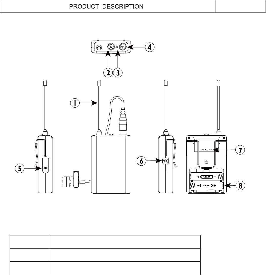
¾ Bodypack Transmitter
WIRELESS
5
1. Antenna
2. Power Button
3. Power / LED: Indicate the power / low battery level status.
4. Mini XLR Connector: Connect to the lapel microphone or headset microphone.
5. Channel Selector: Changes the Channel setting from 1 to 16.
6. Gain: The rotary control adjusts the input audio level of the transmitter. The gain
adjustment range is 10dB.
7. MIC/LINE Switch: The switch set the audio input to MIC level or LINE level.
8. Battery component: Insert two AA dry or rechargeable batteries into the compartment
and make sure that the polarity of batteries is correct.
LED Indicator Status
Red Ready
Flashing Red Low Battery power when less than 10 minutes operation
6
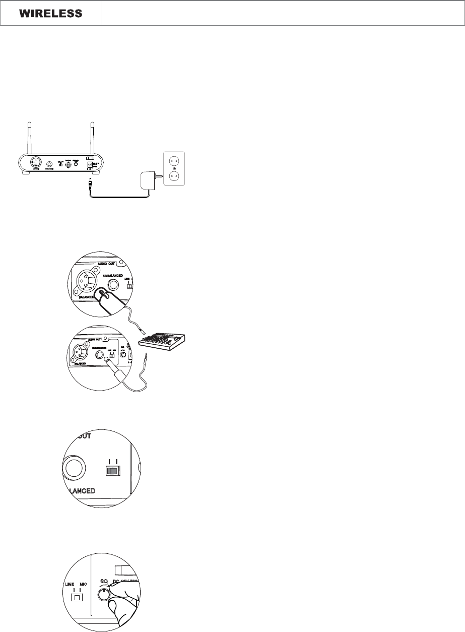
Connected the provided DC power supply to the
receiver power input with an appropriate AC
power source. The power LED will light
and the receiver is on.
¾
Using a standard audio cable with 3-pin XLR
connectors or 6.3mm phone plugs to connect
the mixer or amplifier.
¾
Set the audio output level for
MIC: -20dB
LINE: 0dB
¾
Never use the balanced and unbalanced audio
outputs at the same time! This may cause
signal loss or increased noise.
zConnecting the receiver
Prior to setting up, please check that the transmitter and receiver are tuned to the same
frequency or channel. Two or more transmitters operating in the same frequency can
not be used at the same time and area.
1
2
3
4
AC/DC
ADAPTER
LINE MIC
Use squelch to avoid reproducing noise when
the receiver does not receive enough signal from
the transmitter.
¾
Turn clockwise to increase squelch and reduce
noise. When turning the squelch knob clockwise,
it begins to eliminate background noise.
-
When the squelch is all the way to the left, the
squelch is off and the ambient RF noise will be
easily to receive.
-
SYSTEM OPERATION
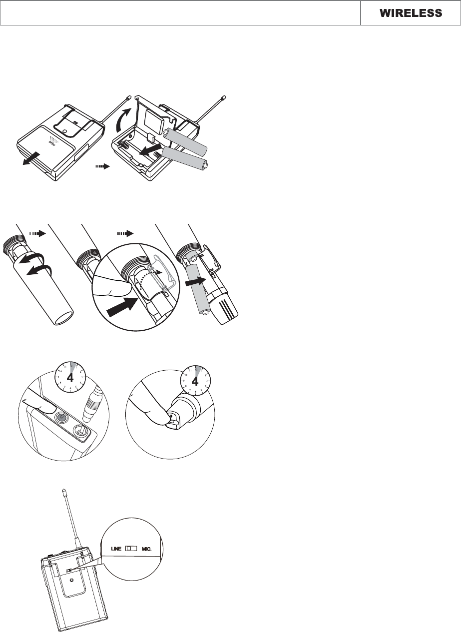
Open the battery cover and insert batteries
into the battery compartment conforming
to the polarity (+)(-) marks.
¾
Unscrew the handheld Mic and open the
battery cover to insert the battery into the
battery compartment and confirm the
marks of the polarity (+) (-).
¾
Press for 4 seconds to turn the Handheld/
Bodypack transmitter on.
¾
If the LED stays flashing , it indicates that
the battery will out of power soon and
should be changed.
zSet up the handheld microphone / bodypack transmitter
NOTE: When you don’t use this device for a long term period, please switch the power
switch to “off” mode to save more electric power.
SYSTEM OPERATION
Adjust the audio input level.
¾
7

WIRELESS TROUBLE SHOOTING
z
Troubleshooting
Problem Solution
No sound ¾ Check the power supply of the microphone and receiver.
¾ Check that the transmitter and receiver are tuned to the same
frequency.
¾ Check whether the hi-fi appliance is switched on and the receiver
output is connected to audio mixer or amplifier input.
¾ Check whether transmitter is too far away from receiver or
SQUELCH control set too high.
¾ Check whether receiver is located too near metal object or there
are obstructions between transmitter and receiver.
Sound interference ¾ Check the antenna location.
¾ When using 2 or above microphone sets simultaneously, make
sure that the chosen frequencies are not interfered.
¾ Check whether the interference comes from other wireless
microphones, TV, radio and etc.
Distortion ¾ Check the receiver volume level is set too high or too low.
¾ Check whether the interference comes from other wireless
microphones, TV, radio and etc.
z
System Feature
¾ Operating in UHF band frequency with synthesizer controlled.
¾The wireless microphone system with 16 selectable frequencies via Phase Locked Loop (PLL)
circuitry makes it easy to choose non-interfered channels.
¾ Diversity with two antennas to ensure the reception quality.
¾Super high sensitivity, extremely low noise transmission and reception.
¾ SMT assembled PCB module ensures the quality and stability.
8

WIRELESS
FEATURES & SPECIFICATION
z
System Specification
Receiver
Handheld Microphone/Bodypack Transmitter
DESIGN AND SPECIFICATIONS SUBJECT TO CHANGE WITHOUT NOTICE.
: UHF 520 - 698MHz
: Mini case
: PLL Synthesized
: FM ±20KHz
: ±0.005%
: >
: >50dB
: 80Hz to 18KHz
: <1% (at 1KHz)
: 1st: 243.95MHz 2nd:10.7MHz
: >100dB
: 32.768KHz
: Balanced & Unbalanced
: 120mA ± 10mA
: 170×42×106
¾
¾Case
¾
¾
¾
¾
¾
¾
¾ Selectivity
¾
¾ T.H.D.
¾
¾
¾
¾
¾
¾
¾Dimension (mm)W×H×D
¾
¾ Channel Select
¾
¾
¾
¾ Deviation
¾
¾ T.H.D.
¾
¾ Tone Key
¾ Mic Unit
¾
¾Dimension (mm)W×H×D
: UHF 520 -698 MHz
: 10mW (MAX)
: PLL Synthesized
: ± 0.005%
: <1% (at 1KHz)
: 32.768KHz
: 120mA ± 10mA
9

440-0083-0
FCC Caution: To assure continued compliance, any changes or modifications not expressly approved by
the party responsible for compliance could void the user's authority to operate this equipment. (Example -
use only shielded interface cables when connecting to computer or peripheral devices).