Mascot Electric UF-9R Wireless Handheld Transmitter Microphone User Manual UR UF 9R
Mascot Electric Co., Ltd. Wireless Handheld Transmitter Microphone UR UF 9R
User Manual
DC OUT
M
U
T
E
O
N
O
F
F
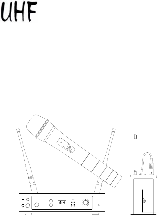
WIRELESS
MICROPHONE
SYSTEM
USER’S MANUAL
BAND

WIRELESS MICROPHONE SYSTEM
1. Introduction
………………………………………….……….……….……
1
2. Safety …………………………………………………………………………
1
3. Environment
………………………………………………………………...
1
4. Wireless Note……………………………………………….……………...
1
5. Product Description ………………………………..………….………..…
5.1 Receivers
5.1.1 True-diversity type
5.1.2 Switching-diversity type
5.1.3 Non-diversity type
5.3 Handheld Microphone
5.4 Bodypack Transmitter
2
6. Basic Connections……………….…………………..……….…..……..…
7. Setting Up ………………………………………………….………...……
7.1 Connecting the receiver to power
7.2 Connecting the receiver to an audio mixer or an amplifier
7.3 Inserting batteries into the handheld / bodypack transmitter
7.4 Setting up the handheld transmitter
7.5 Setting up the bodypack transmitter
8. Trouble-shooting ……………………………………..………….…….….
9. System Feature……………………………………….…………………...
10. System Specification…………………………………………..……….
10
Table of Contents

WIRELESS WIRELESS NOTE
1
Wireless Microphone
FCC Statement
This device complies with part 15 of the FCC rules. Operation is subject to the following two
conditions: (1)This device may not cause harmful interference and (2) This device must accept
any interference received, including interference that may cause undesired operation
Notice : The changes or modifications not expressly approved by the party responsible for
compliance could void the user’s authority to operate the equipment.
IMPORTANT NOTE: To comply with the FCC RF exposure compliance requirements, no
change to the antenna or the device is permitted. Any change to the antenna or the device
could result in the device exceeding the RF exposure requirements and void user’s authority to
operate the device.
1. Introduction
Thank you for purchasing our product. This wireless microphone system operates in UHF
band frequency with synthesizer controlled. Each system with 16 or 64 selectable frequencies
via Phase Locked Loop (PLL) circuitry makes it easy to choose non-interfered channels.
Please read this instruction manual carefully before operating the system. This manual covers
the function and operation of the wireless microphone system.
2. Safety
Ø Do not spill liquid on the appliance and do not drop it on a hard concrete floor.
Ø Do not place the appliance near heat sources such as radiators, amplifier, or etc. Do not
expose it to direct sunlight, extremely dust, excessive moisture, or vibration.
Ø
Take out the battery from transmitter, if the appliance has been not used for a longer period.
This will avoid the damage resulting from a defective leaking battery
3. Environment
Ø Do not throw used batteries into a fire or garbage bin with domestic rubbish. Be sure to
dispose of used batteries in accordance with local waste disposal rules.
Ø When disposing the equipment, remove the batteries, separate the case, circuit boards,
and cables, and dispose of all components in accordance with local waste disposal rules.
4. Wireless Note
Ø Before setting up, make sure that the transmitter and receiver are tuned to the same
frequency.
Ø Do not use two transmitters in the same frequency.
Ø Use good quality batteries to avoid the damage resulting from a defective leaking battery.
Ø Turn the volume control on the receiver to adjust receiver output level to match input level
requirements of an audio mixer or an amplifier. (Refer to 7.2)
Ø To avoid interference, do not put the receiver too near metal object and avoid obstructions
between transmitter and receiver.
Ø Avoid the interference from TV, radio, other wireless appliances and etc.
AUDIO OUTPUT
UNBALANCED
ANT B
BALANCED
DC OUT
8V/80mA
ANT A
8V/80mA
DC OUT
DC ONLY
12V 1A
SQUELCH
DC OUT
8V/80mA
ANT A
DC OUT
8V/80mA
DC OUT
ANT B
SQUELCH
BALANCED
UNBALANCED
AUDIO OUTPUT
SQUELCH
BALANCED
AUDIO OUTPUT
UNBALANCED
DC OUT
12V 1A
DC ONLY
2
Wireless Microphone
WIRELESS PRODUCT DESCRIPTION
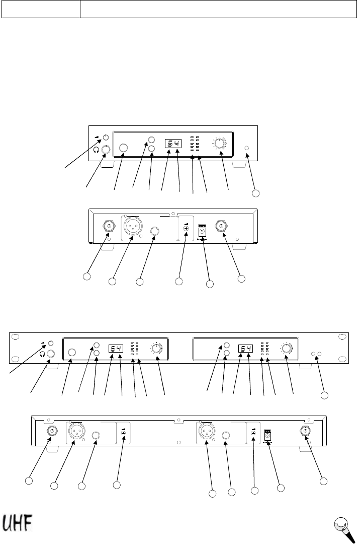
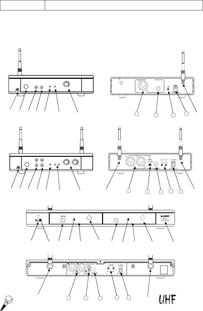
5. Product Description
5.1 Receivers
The receiver operates in UHF band frequency with PLL synthesizer control. They are used with all
our 16- or 64-selectable channels transmitters. Powered by 12V DC.
5.1.1 Diversity Type Receiver
¬
-
®
¯
°
±
²
11
13
14
´
µ
12
Single channel, 1/2 rack
Dual channel, full rack
³
12
1 5
1 6
¬
-
®
¯
°
±
²
11
´
µ
¯
°
±
´
µ
²
³
13
14
12
12
1 5
1 6
13
14
1 5

WIRELESS PRODUCT DESCRIPTION
1.
Headphone Monitor Volume Control:
Rotate this knob to control headphone volume
level.
2. Headphone Input Connector: Plug headphone into this 6.3j connector to monitor
receiver audio.
3. Power: Pushes the receiver on and off.
4. Group Selector: Rotates this selector to choose a displayed group number.
5. Channel Selector: Rotates this selector to choose a displayed channel number.
6. Group LED Display: Displays group number.
7. Channel LED Display: Displays channel number.
8. RF Level Indicators: Five LEDs per RF antenna channel glow to indicate RF signal
strength. The more LEDs that glow, the stronger the received signal. If none of these
LEDs glow, no signal is being received.
9. AF Level Indicators: Five LEDs glow to indicate audio signal strength. Green indicates
normal operation. RED indicates approaching overload condition.
10. Level Control: This rotary control adjusts the receiver output level to match the input
sensitivity of a mixer or amplifier
11. DC Out: Connect the supplied DC1.5 cable to the receiver and the microphone, and it
takes around 10 hours to recharge and the LED of transmitter is flashing all the time.
12. Antenna Input Connector: TNC-type connectors provide connection to the supplied
antennas or to coaxial cable used with an antenna divider, antenna boosters or remote
antennas.
13. Balanced Output: 3-pin XLR connector provides balanced low-impedance output.
14. Unbalanced Output: 6.3j phone jack provides unbalanced low-impedance output.
15. Squelch: The squelch adjusts the output level to suppress the noise. Setting the
squelch too high will reduce the usable range of the system. Set the squelch to minimum
before turning the receiver on.
16. DC IN: Input connector for the supplied AC adapter.
3
Wireless Microphone
12V 500mA
AUDIO OUTPUT
BALANCED
SQUELCHUNBALANCED
DC ONLY
DC OUT
37
1
5 5
1
7 3
¬
-
®
°
µ
³
WIRELESS PRODUCT DESCRIPTION
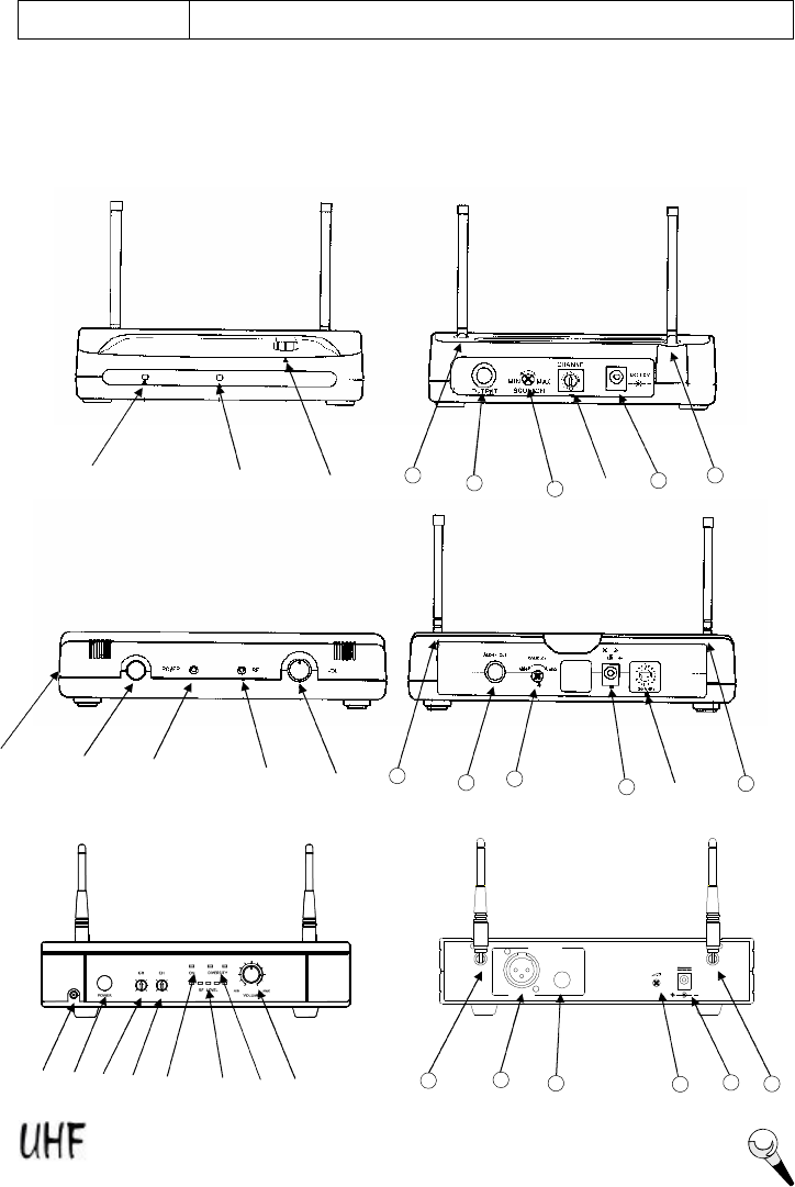
5.1.2 Switching-diversity Type
.
Single Channel, Diversity, 1/2 Rack
15
16
17
¯
È
11
®
°
µ
²
¬
-
®
°
µ
Æ
15
16
11
15
16
17
11
13
11
11
11
17
Single Channel, Diversity, Mini Case
Single Channel, Diversity, Mini Case
4
Wireless Microphone
POWER VOLUME
DC OUT
3
GR
7
1
5RF LEVEL
DIVERSITY
CH
5
1
7 3
ON
MIN MAX
12V 500mA
AUDIO OUTPUT
BALANCED
SQUELCHUNBALANCED
DC ONLY
UNBALANCEDBALANCED2 1
ON
AUDIO OUTPUT
MIXING
OFF
CH 2 CH 1
SQUELCH DC ONLY
12V 1000mA
CHANNEL
POWER
9
1
13
DIVERSITY
RF SIGNAL
5
AF
MIN
VOLUME
MAX
MIN
VOLUME
MAX
CHANNEL
13 5
9
1
VOLUMEVOLUME
AF DIVERSITY
MINMIN
RF SIGNAL
MAXMAX
Single Channel, Diversity, 1/2 Rack
Detachable Antenna
¬
-
®
°
µ
´
¯
Ç
15
16
17
12
WIRELESS PRODUCT DESCRIPTION
12
13
¬
-
®
°
±
²
°
´
µ
15
12
13
³
14
±
´
³
16
12
17
¬
-
®
°
±
²
°
´
µ
³
±
´
³
15
11
13
14
16
17
11
Dual Channel, Diversity, full Rack
Detachable Antenna,
Dual Channel, Diversity, full Rack
5
Wireless Microphone

1.
DC Out:
Connect the supplied cable to the receiver and the microphone, and it takes
around 10 hours to recharge and the LED of transmitter is flashing all the time.
2. Power: Pushes the receiver on and off.
3. Power Indicator: The indicator LED lights when the receiver is ready to operate.
4. Group Selector: Changes receiver Group setting. (for 64-selectable channels)
5. Channel Selector: Changes receiver Channel setting.
6. AF Indicator: The indicator glows to indicate that audio signal has been received.
7. RF Indicator: This LED lights to indicate that signal is being received.
8. RF Level Indicators: Five LEDs per RF antenna channel glow to indicate RF signal
strength. The more LEDs that glow, the stronger the received signal. If none of these
LEDs glow, no signal is being received.
9. Diversity A.B Indicator: This LED lights to show that antenna has received the RF signal.
10. Level Control: This rotary control adjusts the receiver output level line level to match the
input sensitivity of the audio mixer or amplifier.
11. Antenna: Fixed-length UHF antenna permanently mounted either on rear panel.
12. Antenna Input Connector: TNC-type connectors provide connection to the supplied
antennas or to coaxial cable used with an antenna divider, antenna boosters or remote
antennas.
13. Balanced Output: 3-pin XLR connector provides balanced low-impedance output .
14. Mixing Switch: When the MIXING switch is in the OFF position, the XLR output for
channels 1 and 2 are separate. When the MIXING switch is in the ON position, the XLR
output for channels 1 and 2 are mixed, so that both XLR outputs have combined signal from
both channel 1 and channel 2.
15. Unbalanced Output: 6.3j phone jack provides unbalanced low-impedance output.
16. Squelch Adj. : The squelch adjusts the output level to prevent from the external noise.
Setting the squelch too high will reduce the usable range of the system. Set the squelch to
minimum before turning the receiver on.
17. DC Jack: DC input connector for the supplied AC adapter.
WIRELESS PRODUCT DESCRIPTION
6
Wireless Microphone
12V 300mA
SQUELCHUNBALANCED
AUDIO OUTPUT
BALANCED
DC ONLY
VOLUMEPOWER
DC OUT
3
GR
7
1
5
CH
5
1
7 3
RFON MIN MAX
VOLUME 2
GR CH VOLUME 1POWER
DC OUT
3
3
5
1
7
7
1
5RF SIGNAL
MIC 1
MIC 2
37
1
5
5
1
7 3
ON
F1 F2
MIN MAX MIN MAX
POWER
9
1
13
DIVERSITY
RF SIGNAL
5
AF
MIN
VOLUME
MAX
MIN
VOLUME
MAX
CHANNEL
13 5
9
1
VOLUMEVOLUME
AF DIVERSITY
MINMIN
RF SIGNAL
MAXMAX
WIRELESS PRODUCT DESCRIPTION
Single Channel, Non-Diversity
Dual Channel, Non-Diversity
¬
-
®
°
µ
¯
¬
-
®
°
²
µ
¯
14
15
11
12
14
15
12
13
11
²
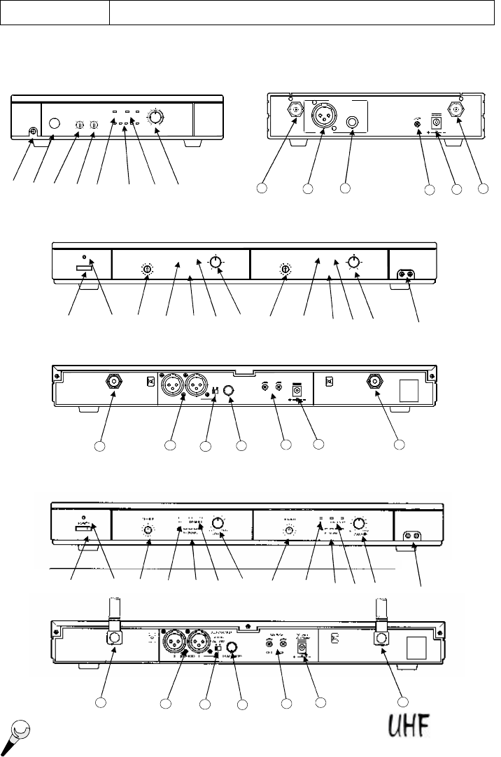
5.3 Non-diversity Type Receiver
Dual Channel, Non-Diversity
¬
-
®
°
±
µ
°
´
µ
³
±
´
³
14
15
12
13
11
È
È
µ
7
Wireless Microphone

1.
DC Out:
Connect the supplied cable to the receiver and the microphone, and it takes
around 10 hours to recharge and the LED of transmitter is flashing all the time.
2. Power: Pushes the receiver on and off.
3. Power Indicator: The indicator LED lights when the receiver is ready to operate.
4. Group Selector: Changes receiver Group setting. (for 64-selectable channels)
5. Channel Selector: Changes receiver Channel setting.
6. AF Indicator: The indicator glows to indicate that audio signal has been received.
7. RF Indicator: This LED lights to indicate that signal is being received.
8. RF Level Indicators: Five LEDs per RF antenna channel glow to indicate RF signal
strength. The more LEDs that glow, the stronger the received signal. If none of these
LEDs glow, no signal is being received.
9. Level Control: This rotary control adjusts the receiver output level to match the input
sensitivity of the audio mixer or amplifier.
10. Antenna: Fixed-length UHF antenna permanently mounted on rear panel.
11. Balanced Output: 3-pin XLR connector provides balanced low-impedance output.
12. Mixing Switch: When the MIXING switch is in the OFF position, the XLR output for channels
1 and 2 are separate. When the MIXING switch is in the ON position, the XLR output for
channels 1 and 2 are mixed, so that both XLR outputs have combined signal from both
channel 1 and channel 2.
13. Unbalanced Output: 6.3j phone jack provides unbalanced low-impedance output.
14. Squelch Adj. : The squelch adjusts the output level to prevent from the external noise.
Setting the squelch too high will reduce the usable range of the system. Set the squelch to
minimum before turning the receiver on.
15. DC Jack: DC input connector for the supplied AC adapter.
WIRELESS PRODUCT DESCRIPTION
8
Wireless Microphone
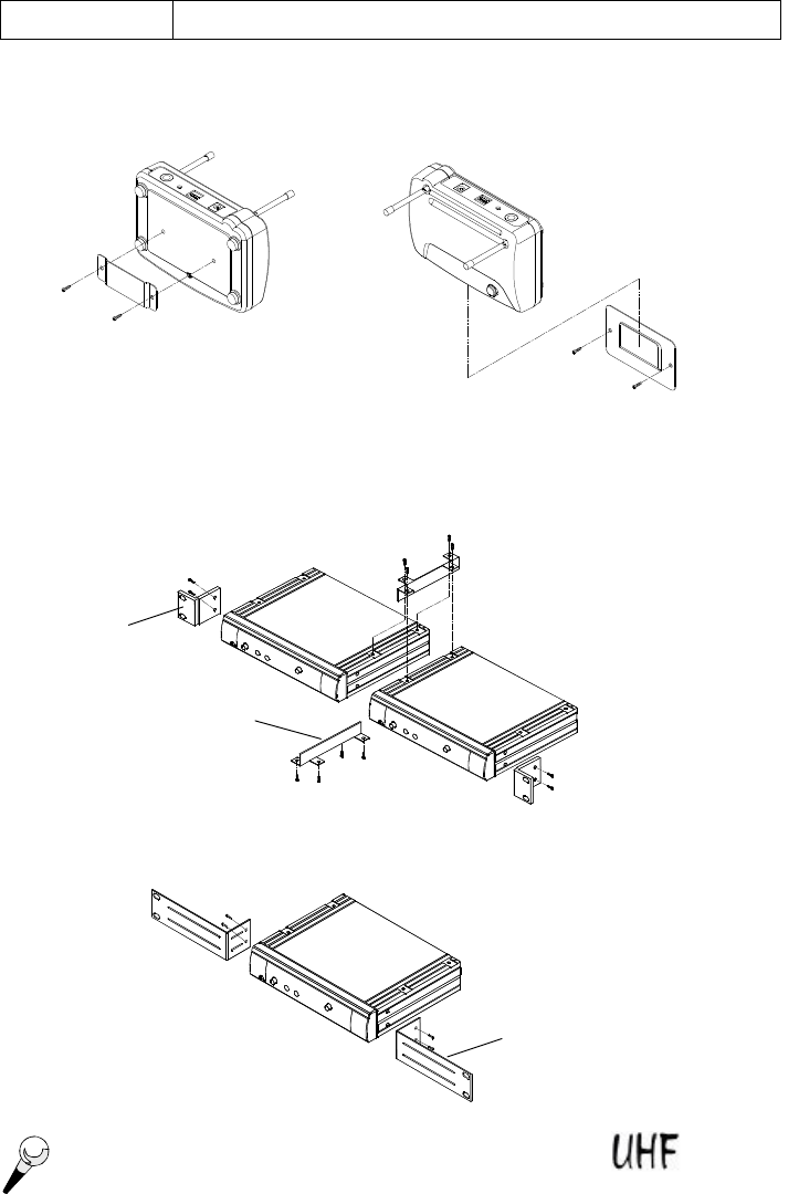
To mount a receiver in a 19” standard rack by using 2 L type long metal racks (L1).
(L1 is an optional product, so please purchase extra in local shops.)
To combine two receivers in a 19” standard rack by using 2 short L type plastics racks (L2) and
2 metal connecting plates (C1). (Each system includes a L2 and a C1.)
L1
L2
C1
WIRELESS PRODUCT DESCRIPTION
The detachable clip on the bottom of receiver is designed to hang on the supplied hook for
flexible location, such as on speaker amplifier, guitar amplifier or wherever you want.
Wireless Microphone
9
DC OUT
37
1
5 5
1
7 3
or
OPEN
or
CHANNEL
POWER
9
1
13
DIVERSITY
RF SIGNAL
5
AF
MIN
VOLUME
MAX
MIN
VOLUME
MAX
OPEN
CHANNEL
13 5
9
1
VOLUMEVOLUME
AF DIVERSITY
MINMIN
RF SIGNAL
MAXMAX
WIRELESS PRODUCT DESCRIPTION
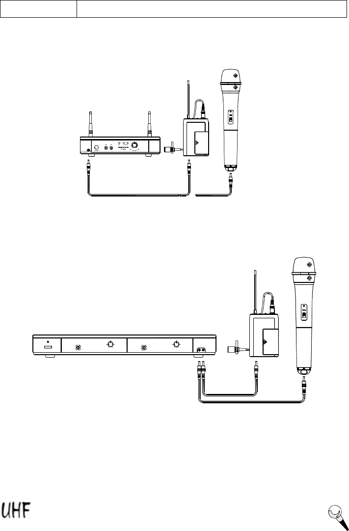
Charging Connecting Diagram
Connect the supplied DC1.5 cable to the receiver and the microphone, and it takes around 10
hours to recharge and the LED of transmitter is flashing all the time.
Wireless Microphone
10
-
D
C
V
2
1
N
G
I
H
C
R
A
G
U
T
P
I
N
5
CH
5
7 3
1
GR
1
7 3
OFF
CH
CH
MUTE
ON
WIRELESS PRODUCT DESCRIPTION
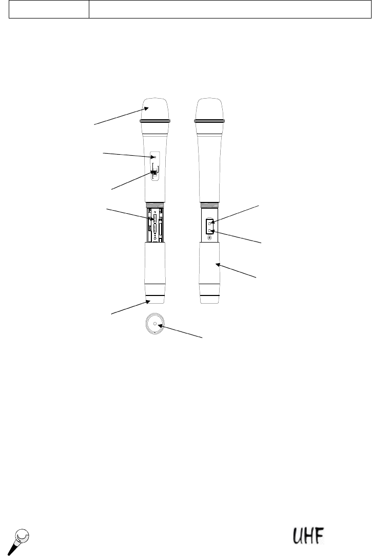
5.3 Handheld Microphone
The handheld microphone operates in UHF band frequency with PLL synthesized control. UHF
16 or 64 preprogrammed selectable frequencies to avoid interference. Uni-directional dynamic
or uni-directional electret condenser cartridges with different characters for various choices.
Use 1.5V x 2 AA size batteries for low operating cost.
1. Grille: Protects the microphone capsule and helps reduce breath sounds and wind noise.
2. Low Battery LED: LED indicates battery status. Switching the power to "ON", the LED
flashing once indicates that the transmitter has sufficient power. If the LED stays on, it
indicates that the battery has insufficient power and should be changed soon. If the status
LED fails to flash, the battery is either dead or not positioned correctly, and you should
correct the positioning or change the battery.
3. On/off Switch: Turns transmitter power on and off.
4. Battery Compartment: Insert two AA batteries into the compartment and make sure that
the polarity of batteries is correct.
5. Group Selector: Changes transmitter group setting. (for 64-selectable channels)
6. Channel Selector: Changes transmitter channel setting.
7. Battery Cover: Unscrew to expose battery compartment and Group/Channel selector.
8. Color Clip: This color clip helps to identify the frequency for multi-channel operation.
9. Charging Input: The inserted rechargeable batteries can be charged by using the supplied
DC-plug cable connection to DC out on the receiver. It takes up to 10 hours for charging.
¬
-
®
¯
°
±
²
³
´
Wireless Microphone
11

WIRELESS PRODUCT DESCRIPTION
5.4 Bodypack Transmitter
The bodypack transmitter operates in UHF band frequency with PLL synthesized control. UHF 16
or 64 preprogrammed selectable frequencies to avoid interference. Uni-directional electret
condenser cartridges with different characters for various choices. Use 1.5V x 2 AA size batteries
for low operating cost.
1.
Mini XLR connector:
The included electret lapel microphone is inserted into the connector
on transmitter.
2. On/Off Switch: Turns transmitter power on and off.
3. Low Battery LED: LED indicates battery status. Switching the power to "ON", the LED
flashing once indicates that the transmitter has sufficient power. If the LED stays on, it
indicates that the battery has insufficient power and should be changed soon. If the status
LED fails to flash, the battery is either dead or not positioned correctly, and you should correct
the positioning or change the battery.
4. Mic/Line Selector: The switch sets the audio input either to microphone level or line level.
5. Antenna: Permanently connected, helical antenna.
6. Group Selector: Changes transmitter group setting. (for 64-selectable channels)
7. Channel Selector: Changes transmitter channel setting.
8. Mic Adj.: The rotary control adjusts the sensitivity of the transmitter’s audio to the level of
the connected lapel microphone or instrument.
9. Mic Unit: The uni-directional electret condenser unit features the wide frequency response
for warm, rich bass and clear sound.
10. Tie Clip: To clip on the tie or lapel.
11. Cable: With mini XLR connector cable to connect the transmitter.
12. Battery Compartment: Insert two AA dry or rechargeable batteries into the compartment
and make sure that the polarity of batteries is correct.
13. Charging Input: The inserted rechargeable batteries are charged by using the supplied
DC-plug cable connection to DC out on the receiver. It takes up to 10 hours for charging.
¬
-
®
¯
°
±
²
³
´
µ
12
13
11
Wireless Microphone
12
SQUELCH
AUDIO OUTPUT
DC OUT
8V/80mA
BALANCED
ANT B UNBALANCED
DC OUT
8V/80mA
12V 300mA
DC ONLY ANT A
AUDIO MIXER
AMPLIFIER
LOUDSPEAKER
LOUDSPEAKER
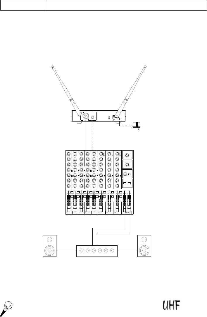
WIRELESS BASIC CONNECTIONS
6. Basic Connections
Connect the receiver output to the audio mixer or amplifier input, using a standard audio cable
with 3-pin XLR connectors or 6.3j phone plugs. Never use the balanced and unbalanced
audio outputs at the same time! This may cause signal loss or increased noise.
Wireless Microphone
13
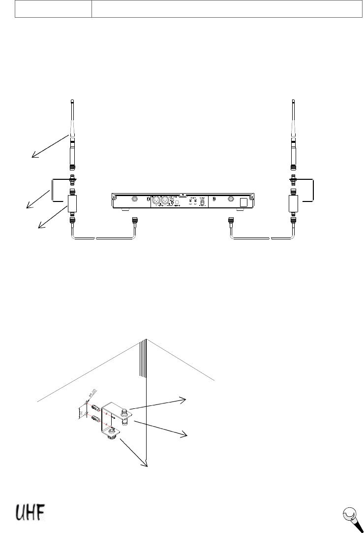
WIRELESS BASIC CONNECTIONS
AB-8A, the antenna booster is highly recommended for long-distance purpose, such as in stadium
or in auditorium. By means of antenna holder, the antenna and booster can put wherever you
want. It is ideal design for multi-channel application. Antenna boosters are applied to the
receivers, which have detachable antennas.
Antenna holder makes it easy to fix wherever for connection antenna and booster. AH-1 can
be assembled on the mic stand or on the wall.
TNC female connector for connecting with
UHF antenna
TNC female connector for connecting with
cable or AB-8A antenna booster (long distance
required)
Screw adapter to screw AH-1 on a
microphone stand.
AB-8A
AH-1
Antenna
Wireless Microphone
14
MAXMIN
VOLUME
VOLUME
MIN MAX
WIRELESS SETTING UP
7. Setting Up
NOTICE: Prior to setting up, check that the transmitter and receiver are tuned to the same
frequency. Two or above transmitters operating in the same frequency can not be
used at the same time and area, so please select the different frequencies which can
be used simultaneously at local area.
7.1 Connecting the receiver to power
Ø Plug the antennas into the TNC socket on the receiver, if the antennas are detachable and point
them upward.
Ø Check that the voltage of the supplied AC adapter conforms to the voltage (AC110 or 220)
available in local area. Using the wrong AC adapter may cause irreparable damage to the unit.
Ø Plug the feeder cable of the supplied AC adapter into DC IN socket on the receiver. Then plug
the AC adapter into a power outlet.
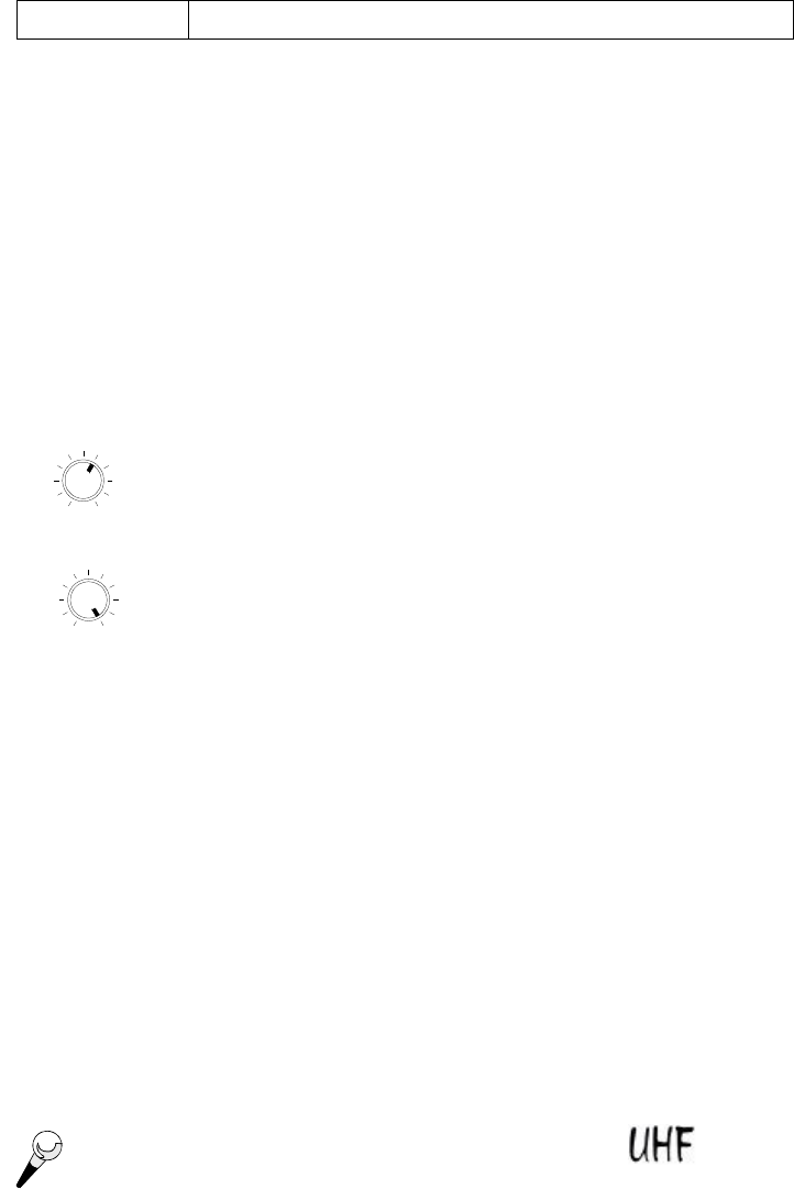
7.2 Connecting the receiver to an audio mixer or an amplifier
In order to make sure the sound quality and avoid distortion, please adjust the volume level
according to following instructions.
Ø When using a standard audio cable with 3-pin XLR connectors or 6.3
j
phone
plugs to plug into the MIC IN on the audio mixer or on the amplifier, please turn
the Volume Level Control on the receiver to around 1 o’clock position, the
output level for balanced and unbalanced output is about at 77mV.
Ø When using a standard audio cable with 3-pin XLR connectors or 6.3j phone
plugs to plug into the LINE IN on the audio mixer, please turn the Volume
Level Control to around MAX. on the receiver position, the output level for
balanced and unbalanced output is about at 770mV.
Ø When the MIXING switch is in the OFF position, the XLR output for channels 1 and 2 are
separate. When the MIXING switch is in the ON position, the XLR output for channels 1 and
2 are mixed, so that both XLR outputs have combined signal from both channel 1 and channel
2.
7.3 Inserting batteries into the handheld microphone / bodypack transmitter
Ø Push to open the battery cover and insert batteries into the battery compartment conforming to
the polarity (+)(-) marks. The transmitter can not work with incorrectly inserted batteries.
Ø When push the ON/OFF switch to “ON” to switch the power on, the LED will flash momentarily.
If the battery has sufficient power, the LED flashes once. If the LED stays on, it indicates that
the battery has insufficient power and should be changed soon. If the status LED fails to
flash, the battery is either dead or not positioned correctly, and you should correct the
positioning or change the battery.
Ø Close the battery cover.
Never use the balanced and unbalanced audio outputs at the same time! This may cause
signal loss or increased noise.
Wireless Microphone
15

WIRELESS TROUBLE SHOOTING
8. Trouble-shooting
Problem Solution
No sound Ø Check the power supply of the microphone and receiver.
Ø Check that the transmitter and receiver are tuned to the same
frequency.
Ø Check whether the hi-fi appliance is switched on and the receiver
output is connected to audio mixer or amplifier input.
Ø Check whether transmitter is too far away from receiver or
SQUELCH control set too high.
Ø Check whether receiver is located too near metal object or there
are obstructions between transmitter and receiver.
Sound interference Ø Check the antenna location.
Ø When using 2 or above microphone sets simultaneously, make
sure that the chosen frequencies are not interfered.
Ø Check whether the interference comes from other wireless
microphones, TV, radio and etc.
Distortion Ø Check the gain control (Mic Adj.) for bodypack transmitter is set
too high or too low.
Ø Check whether the interference comes from other wireless
microphones, TV, radio and etc.
7.4 Setting up the handheld microphone transmitter
Ø Switch the receiver power on and check the frequency and volume level.
Ø Switch the transmitter and hi-fi appliance (amplifier, tape deck etc.) power on.
Ø Test the microphone and adjust the levels on your audio mixer or amplifier.
7.5 Setting up the bodypack transmitter
A. Connecting a microphone
Ø Open the battery cover. Push the MIC/LINE switch to “MIC” and use the supplied
screwdriver to adjust the GAIN (MIC Adj.) at appropriate position.
Ø Plug the mini XLR connector of the microphone cable into the audio input connector on the
bodypack transmitter.
Ø Switch the transmitter and hi-fi appliance (amplifier, tape deck etc.) power on.
Ø Test the microphone and adjust the levels on your audio mixer or amplifier.
B. Connecting an instrument
Ø Open the battery cover. Push the MIC/LINE switch to “LINE” and use the supplied
screwdriver to adjust the GAIN (MIC Adj.) at appropriate position.
Ø Plug the 6.3j phone plug of the optional guitar cable to the output jack on the instrument and
the mini XLR into audio input connector on the bodypack transmitter.
Ø Switch the transmitter and hi-fi appliance (amplifier, tape deck etc.) power on.
Ø Play the instrument for testing and adjust the levels on your audio mixer or amplifier.
Wireless Microphone
16

WIRELESS FEATURES & SPECIFICATIONS
9. System Feature
Ø The flexibility and the professional performance are specifically designed for stages,
places of worship, and professional sound installations.
Ø The wireless microphone system with 16- or 64-selectable frequencies via Phase Locked
Loop (PLL) circuitry makes it easy to choose non-interfered channels.
Ø Super high sensitivity, extremely low noise transmission and reception.
Ø SMT assembled PCB module ensures the quality and stability.
10. System Specification
Receiver
Ø Carrier Frequency Range : UHF band 682~928MHz
Ø Oscillator : PLL synthesized, 16-or 64-selectable channels
Ø Frequency Stability : ±0.005%
Ø S/N ratio : >94dB, at 48KHz deviation and 60dBmV antenna input
Ø Image and Spurious Rejection
: 80 dB minimum
Ø Receiving Sensitivity : 8 dBμV.
Ø Selectivity : >50dB
Ø AF Response : 50Hz to 15KHz (±3dB)
Ø T.H.D. : <1% (at 1KHz)
Ø Modulation Mode : FM
Ø IF Frequency : 1st: 56MHz; 2nd: 10.7MHz
Ø Dynamic Range : >96dB
Ø Tone Signal : 32.768KHz
Ø Audio Output : Unbalanced or/and balanced audio outputs
Ø Power Supply : 12V DC
Handheld/Bodypack Transmitter
Ø Carrier Frequency Range : UHF band 682~928MHz
Ø RF Power Output : 10mW (max.)
Ø Oscillator : PLL synthesized, 16-or 64-selectable channels
Ø Frequency Stability : ±0.005%
Ø Maximum Deviation : ±48KHz
Ø Spurious Emission :>60dB below carrier frequency
Ø T.H.D. : <1% (at 1KHz)
Ø Microphone Cartridge : Handheld: uni-directional dynamic or uni-directional electret
condenser unit
Lavalier: uni-directional electret condenser unit
Ø Tone Key : 32.768KHz
Ø Operating voltage : DC1.5V x 2 AA size dry or rechargeable batteries
Ø Current consumption : 65mA ± 5mA
DESIGN AND SPECIFICATIONS SUBJECT TO CHANGE WITHOUT NOTICE.
Wireless Microphone
17