Mascot Electric UT-62 Wireless Bodypack Transmitter Microphone User Manual 01
Mascot Electric Co., Ltd. Wireless Bodypack Transmitter Microphone 01
User Manual
WIRELESS MICROPHONE SYSTEM
SWITCHING-DIVERSITY

4.1 Connecting the Receiver
4.2 Set up channel on receiver
4.2.1 Manual Mode
4.2.2 Auto-Scan Mode
4.3 Set up the handheld microphone / Bodypack transmitter
4.4 Low Battery
4.5 Adjusting Gain
3.1 Receiver
3.2 Handheld Microphone
3.3 Bodypack transmitter
2. System Feature........................................................................ 2
1.1 FCC Statement
1.2 Safety
1.3 Environment
1.4 Wireless Note
3. Product Description.................................................................. 3
1. Introduction............................................................................. 1
4. Set Up...................................................................................... 7
5. Basic Connections................................................................... 12
6. Trouble Shooting...................................................................... 13
7. Specification............................................................................ 14

WIRELESS
WIRELESS NOTE
1.1 FCC Statement
This device complies with part 15 of the FCC rules. Operation is subject to the following two
conditions: (1)This device may not cause harmful interference and (2) This device must
accept any interference received, including interference that may cause undesired operation
Notice : The changes or modifications not expressly approved by the party responsible for
compliance could void the user’s authority to operate the equipment.
IMPORTANT NOTE: To comply with the FCC RF exposure compliance requirements, no
change to the antenna or the device is permitted. Any change to the antenna or the device
could result in the device exceeding the RF exposure requirements and void user’s authority
to operate the device.
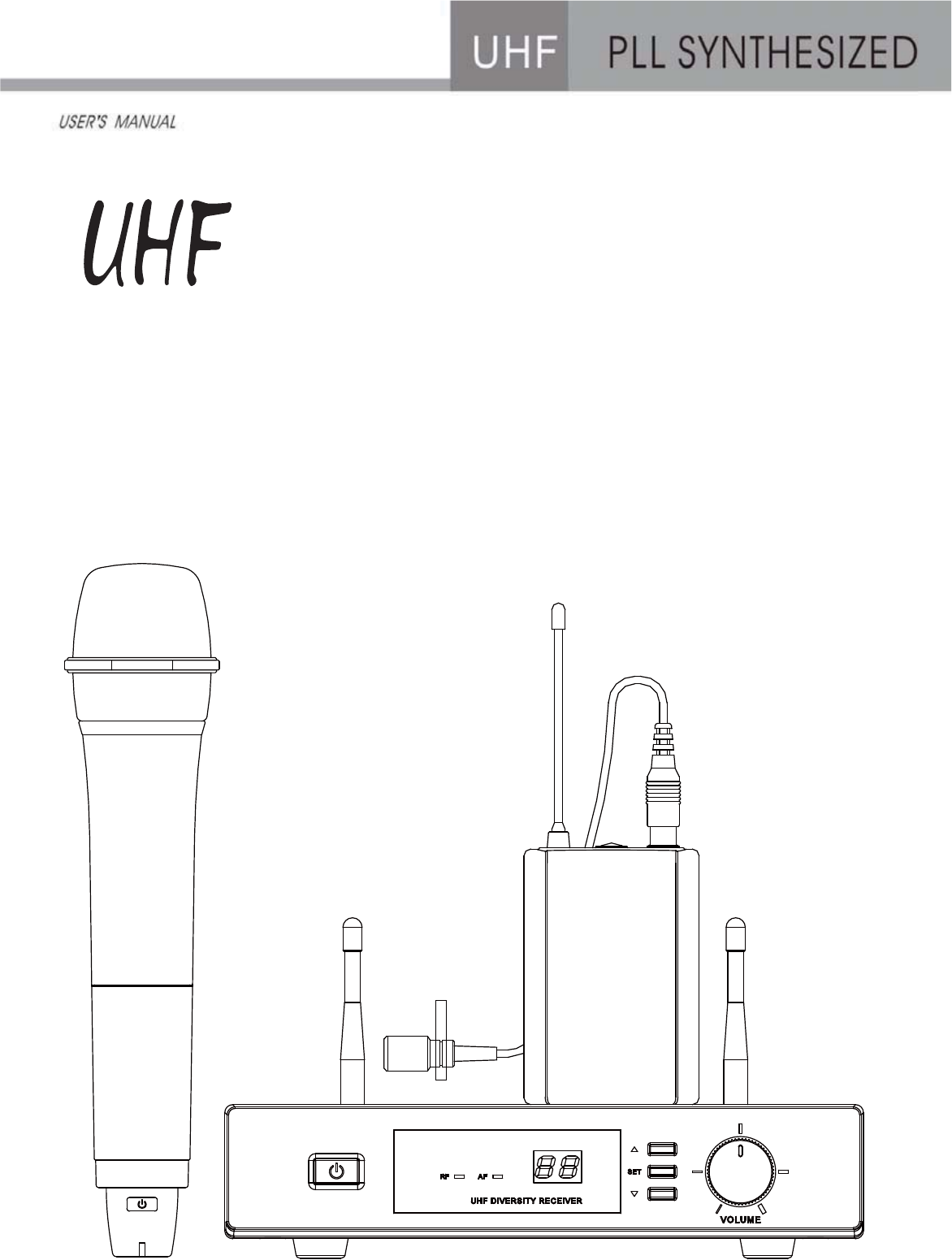
1. Introduction
Thank you for purchasing our product. This PLL synthesized wireless microphone system
operates in UHF band frequency with 16 selectable channels. Please read this instruction
manual carefully before operating the system. This manual covers the function and
operation of the wireless microphone system.
1.2 Safety
¾Do not spill liquid on the appliance and do not drop it on a hard concrete floor.
¾Do not place the appliance near heat sources such as radiators, amplifier, or etc.
¾Do not expose it to direct sunlight, extremely dust, excessive moisture, or vibration.
¾Take out the battery from transmitter, if the appliance has been not used for a longer
period. This will avoid the damage resulting from a defective leaking battery.
1.3 Environment
¾Do not throw used batteries into a fire or garbage bin with domestic rubbish. Be sure to
dispose of used batteries in accordance with local waste disposal rules.
¾When disposing the equipment, remove the batteries, separate the case, circuit boards,
and cables, and dispose of all components in accordance with local waste disposal rules.
1.4 Wireless Note
¾ Before setting up, make sure that the transmitter and receiver are tuned to the same
frequency.
¾Do not use two or above transmitters operating in the same frequency.
¾Use good quality batteries to avoid the damage resulting from a defective leaking battery.
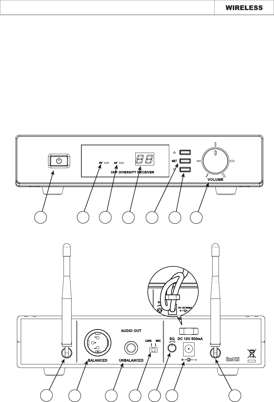
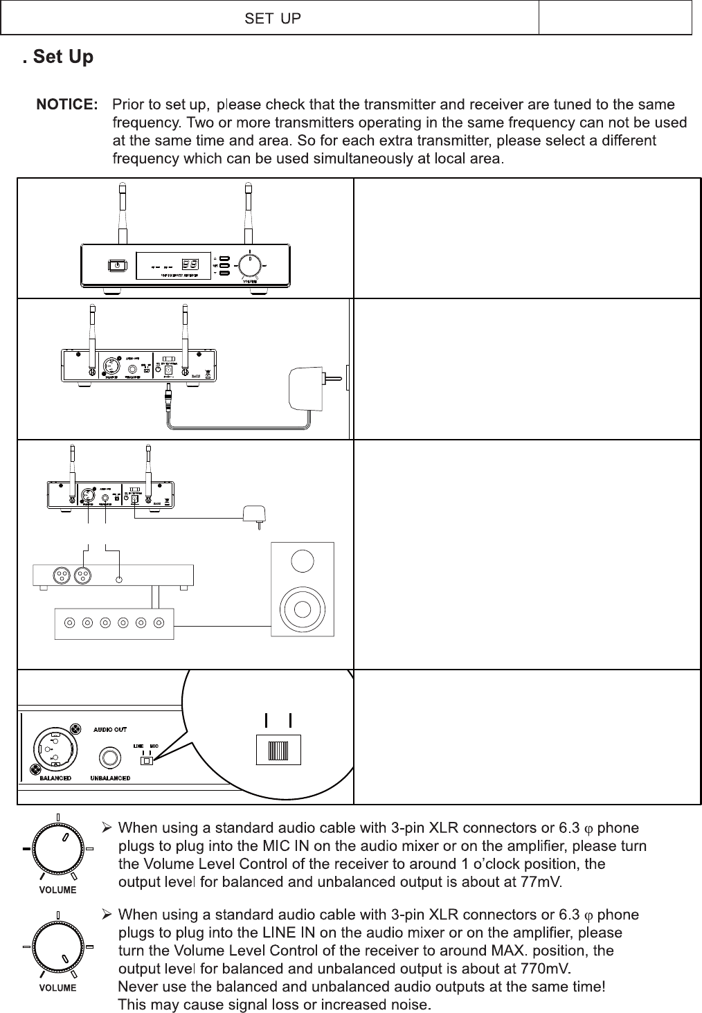
¾Turn the MIC/LINE switch on the rear of receiver to adjust receiver output level to match
input level requirements of an audio mixer or amplifier.
¾While checking sound, move the transmitter around the area where you use the system to
look for dead spots. If you find any dead spot, change the receiver position. If it does
not work, avoid such places.
¾To avoid interference, do not put the receiver too near metal object and avoid obstructions
between transmitter and receiver.
¾Avoid the interference from TV, radio, other wireless appliances and etc.
1

2. System Features
¾Carrier Frequency Range: UHF 520 ~ 930MHz
¾Switching-Diversity technology and adjustable squelch ensures the reception quality.
¾Auto-Scan function can locate the interference-free channel easily.
¾Low noise mixer circuitry helps to reduce the noise from interference to a minimum.
¾Clear status display including RF, AF and channel presence LED.
¾Durable plastic chassis with 1/2 rack design.
¾Balanced XLR connector and unbalanced 1/ 4'' jack audio outputs.
¾The flexibility and the professional performance are specifically designed for stages, places
of worship, and professional sound installations.
¾Operating in UHF band frequency with synthesized controlled.
¾The wireless microphone system with 16 or 64 selectable frequencies via Phase Locked
Loop (PLL) circuitry makes it easy to choose non-interfered channels.
¾Super high sensitivity, extremely low noise transmission and reception.
¾SMT assembled PCB module ensures the quality and stability.
2
SYSTEM FEATURES
PRODUCT DESCRIPTION
3. Product Description
The receivers are used with our 16 channel selectable channels transmitters. (The number of
frequency channels depends on local regulations.) The receiver operates in UHF
band frequency with PLL synthesized control. Powered by 12V DC.
!
3.1 Receiver
3.1.1 Single Channel ( Switching Diversity , Back Antenna )
3
910 11 12 13
5
6
8
14 23 7
8
4
Fixed-length UHF antenna permanently mounted.
2. Button △▽: Used to select your desired mode, and search channel forward.
7.
8.
9.
10.
11.
12.
13.
3. Set Button: Press for 2 seconds. When the LED display is flashing to change the CH.
Release the Set button then LED display flashing five times to lock the setting.
4. LED Display: Showing the channel number.
5. RF indicator: When it receives the signal, the LED will be red light.
6. AF Indicator: When it receives the signal, the LED will be green light.
3.2 Handheld Microphone
The handheld microphone operates in UHF band frequency with PLL synthesized control. UHF
16 preprogrammed selectable frequencies to avoid interference. Uni-directional dynamic or
uni-directional condenser capsules with different characters for various choices. Use 2 x DC1.5V
AA size dry or rechargeable batteries for low operating cost.
5
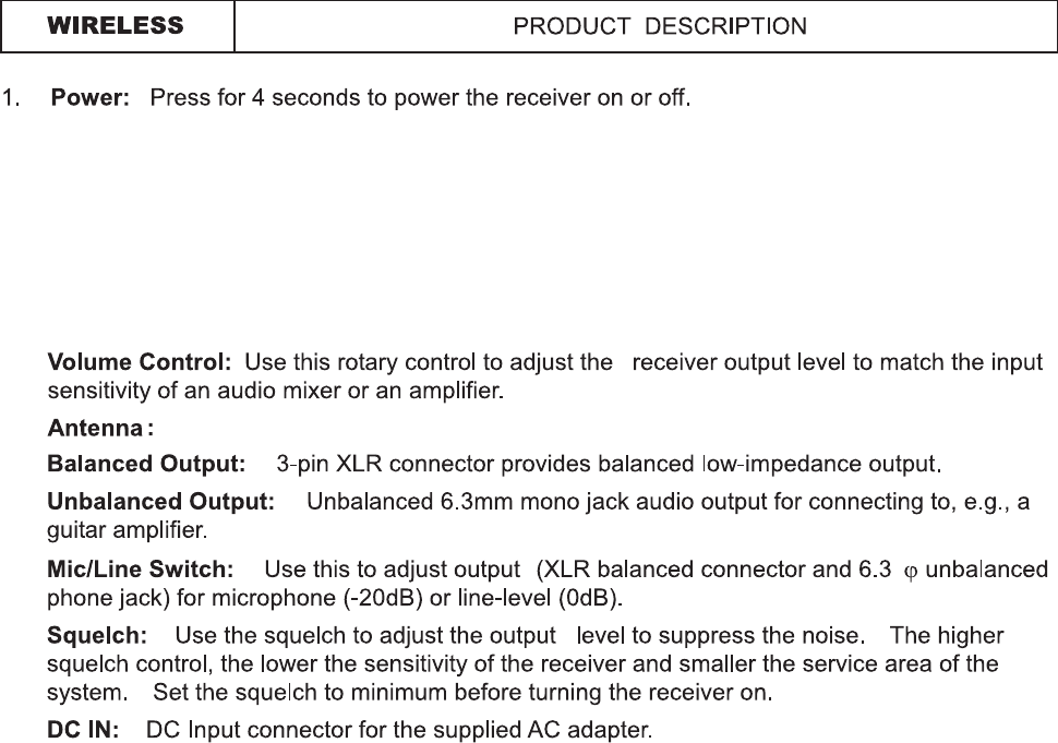
1. Grille: Protects the microphone capsule and helps reduce breath sounds and wind noise. The
grille for the various microphone capsules differ in appearance.
2. Low Battery LED: LED indicates battery life status. When turn on the power, the LED will
stay on to indicate the batteries have sufficient power. Contrarily, if the LED fails to light, the
battery is either dead or not positioned correctly. If the LED stays flashing, it indicates that the
battery will out of power soon and should be changed.
3. Power: Press for 2 seconds to turn transmitter on or off.
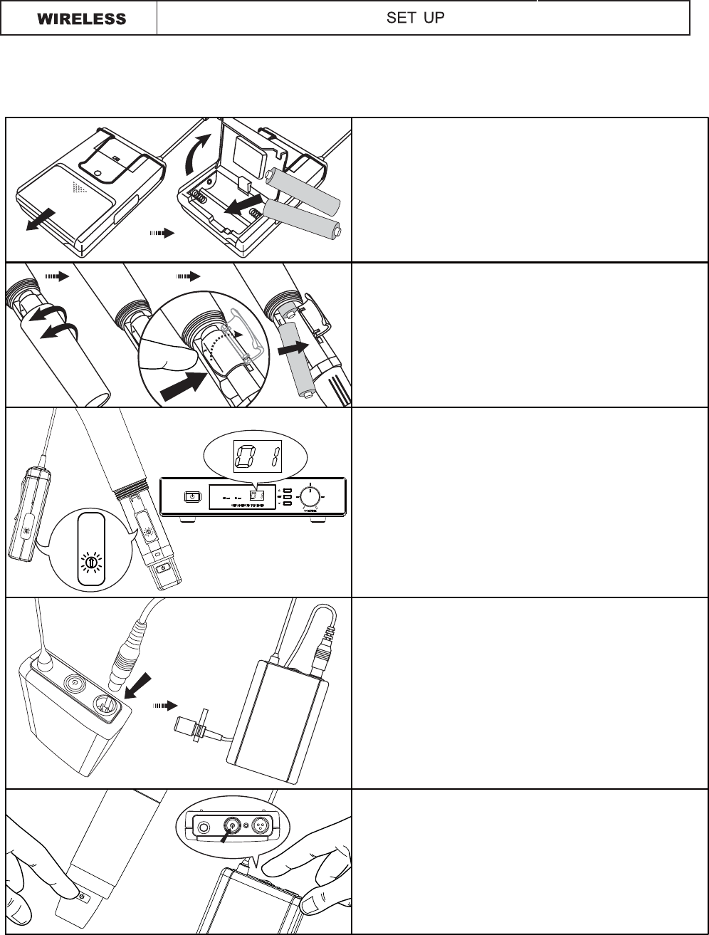
4. Battery Compartment: Insert two AA dry or rechargeable batteries into the compartment and
make sure that the polarity of batteries is correct.
5. Channel Selector: Changes transmitter Channel setting.
6. Battery Cover: Unscrew to expose battery compartment and Channel selector.
7. Color Clip: This color clip helps to mark the same frequency of receiver and transmitter.
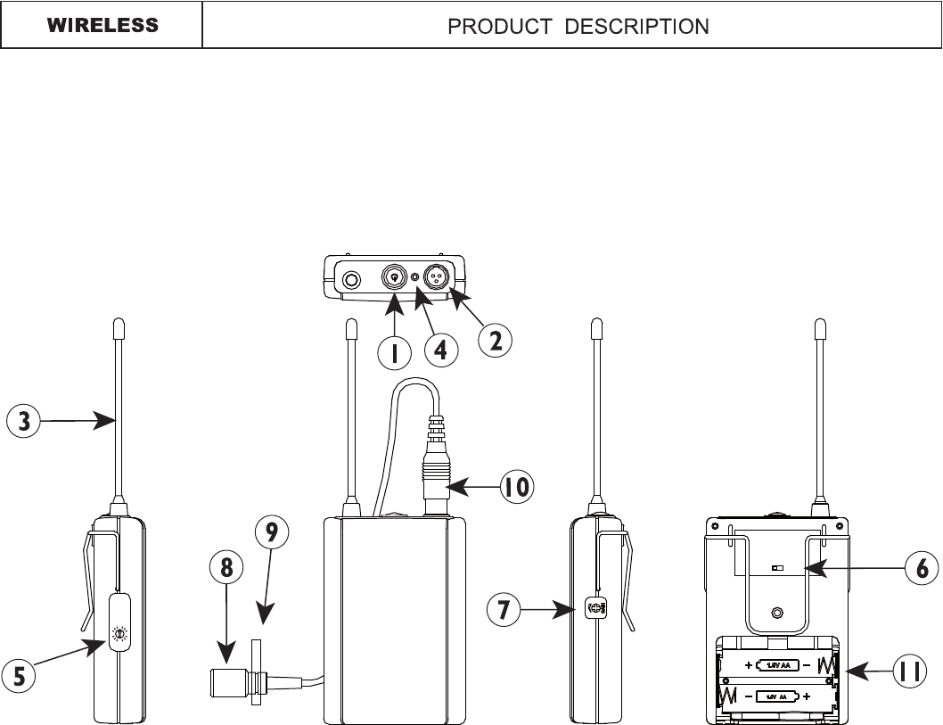
1. Power: Press for 4 seconds to power the transmitter on or off.
2. Mini XLR Connector: The included electret lapel microphone is inserted into the connector
on transmitter.
3. Antenna: Permanently connected, helical antenna.
4. Low Battery LED: LED indicates battery life status. When turn on the power, the LED will
stay on to indicate the batteries have sufficient power. Contrarily, if the LED fails to light, the
battery is either dead or not positioned correctly. If the LED stays flashing, it indicates that the
battery will out of power soon and should be changed.
5. Channel Selector: Changes transmitter Channel setting.
6. Mic/Line Selector: The switch sets the audio input either to microphone level or line level.
7. Gain: The rotary control adjusts the input audio level of the transmitter. The gain adjustment
range is 10dB.
8. Mic Unit: The uni-directional electret condenser unit features the wide frequency response
for warm, rich bass and clear sound.
9. Tie Clip: To clip on the tie or lapel for free-movement.
10. Cable: With mini XLR connector cable to connect the transmitter.
11. Battery Compartment: Insert two AA dry or rechargeable batteries into the compartment and
make sure that the polarity of batteries is correct.
3.3 Bodypack Transmitter
The bodypack transmitter operates in UHF band frequency with PLL synthesized control. UHF
16 preprogrammed selectable frequencies to avoid interference. Uni-directional condenser
cartridges with different characters for various choices. Use 1.5V x 2 AA size dry or rechargeable
batteries for low operating cost.
6
LINE MIC.
4
WIRELESS
7
LINE MIC
AC/DC
ADAPTER
M
7XUQWKHDQWHQQDXSZDUG
4.1 Connecting the Receiver
AC/DC
ADAPTER
R
R LOUDSPEAKER
4.2 Set up interference-free channel on receiver
Notice: Do not put two or more transmitters operate nearby when set up the frequency
channel. Please keep transmitter at least 1 M away from receiver.
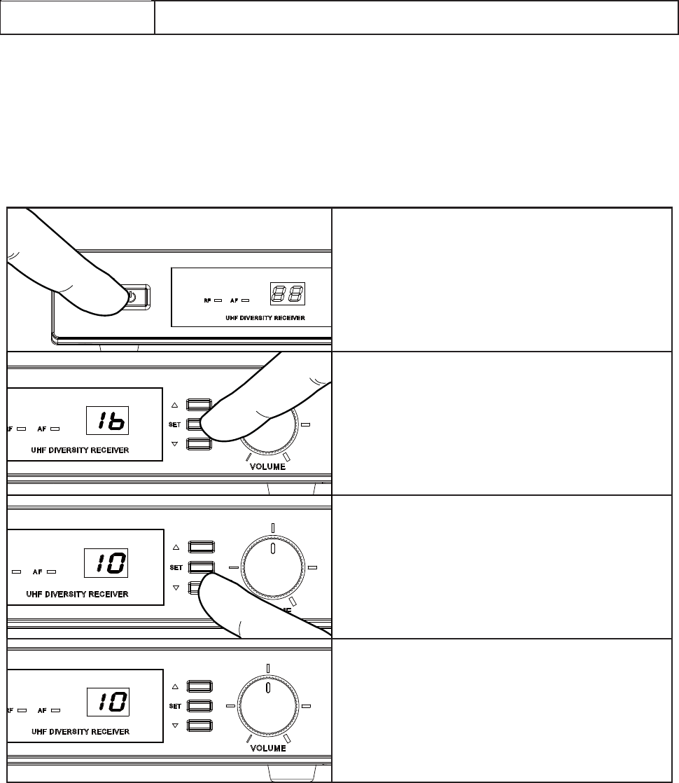
Set up interference -free channel by manual operation.
¾ Press the button to turn the power on.
¾
¾
¾ Stop pressing button and let LED display
flashing five times to lock the setting.
8
Press
△▽
change the channel forward
or backward.
Press button “SET” for 1 second to let
channel flashing on the LED display.
SET UP MANUAL MODE
4.2.1 Manual Mode
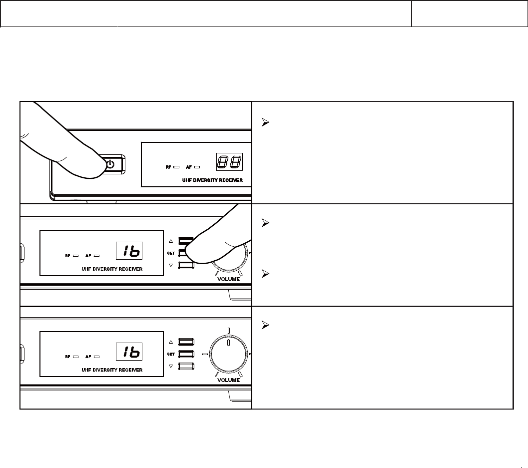
4.2.2 Auto-Scan Mode
Set up interference-free channel by auto-scan programmed search.
Press the button to turn the power on.
Press button “Set” for 3 seconds to
search the next interference-free channel
automatically.
The auto-scan system would stop at the
next interference-free channel.
Stop pressing button and let LED display
flashing five times to lock the setting.
NOTE: If user need to set up a multi-receiver system, please keep your previous
receiver-microphone pair power on. Then go on to next scanning procedure.
9
SET UP
AUTO-SCAN MODE
10
4.3 Set up the handheld microphone / Bodypack transmitter
1
5
9
13
1
5
9
13
1
5
9
13
OPEN
11
4.5 Adjusting Gain
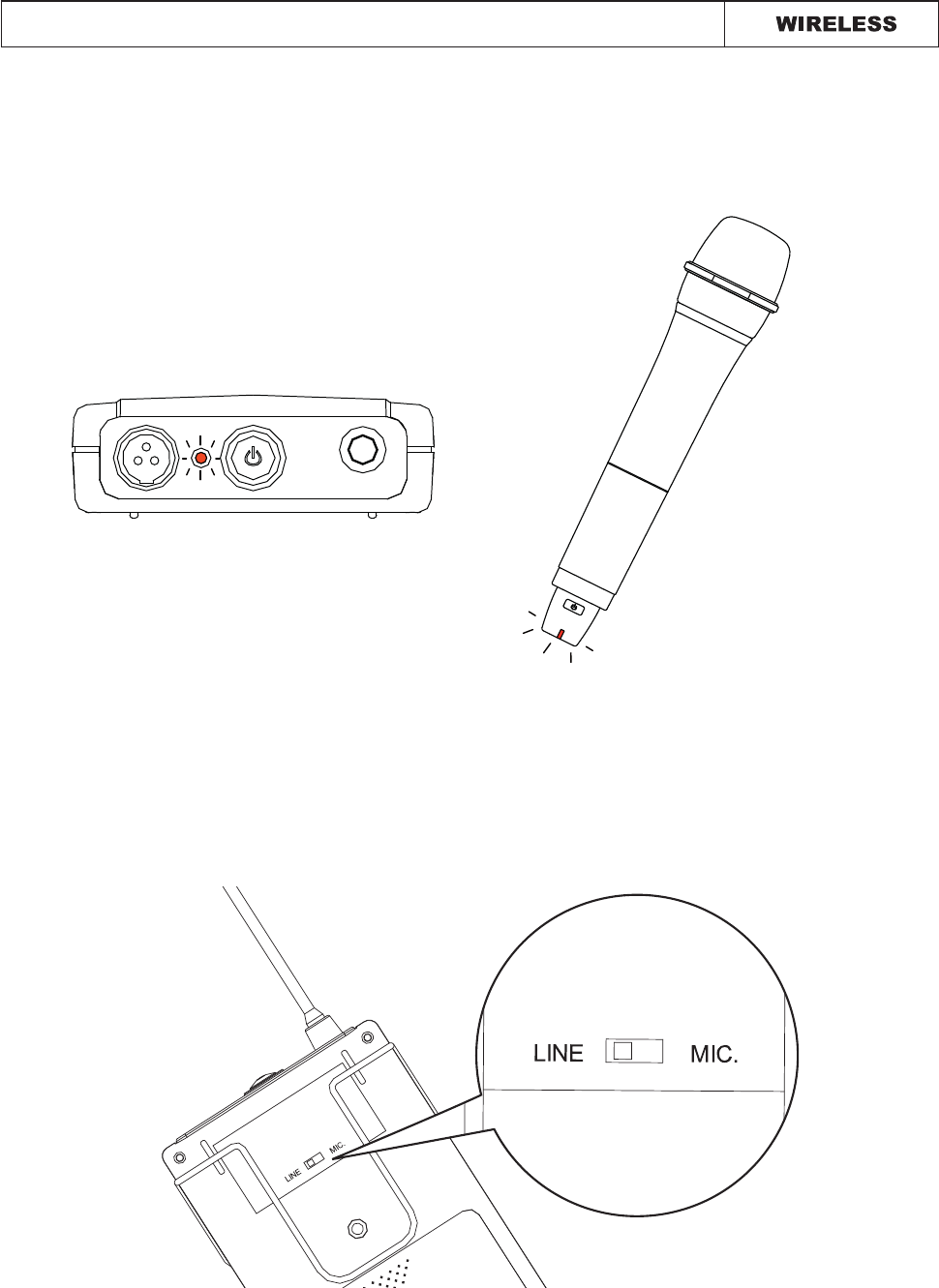
If the LED stays flashing , it indicates that the battery will out of power soon and should be
changed.
Use MIC/LINE switch to adjust the input level. Switching the selector to the Mic position when
connect with microphone for the normal audio input level. Switching the selector to the Line
position when connect with instrument for the high audio input level.
4.4 Low Battery
SET UP
12
L4
L3
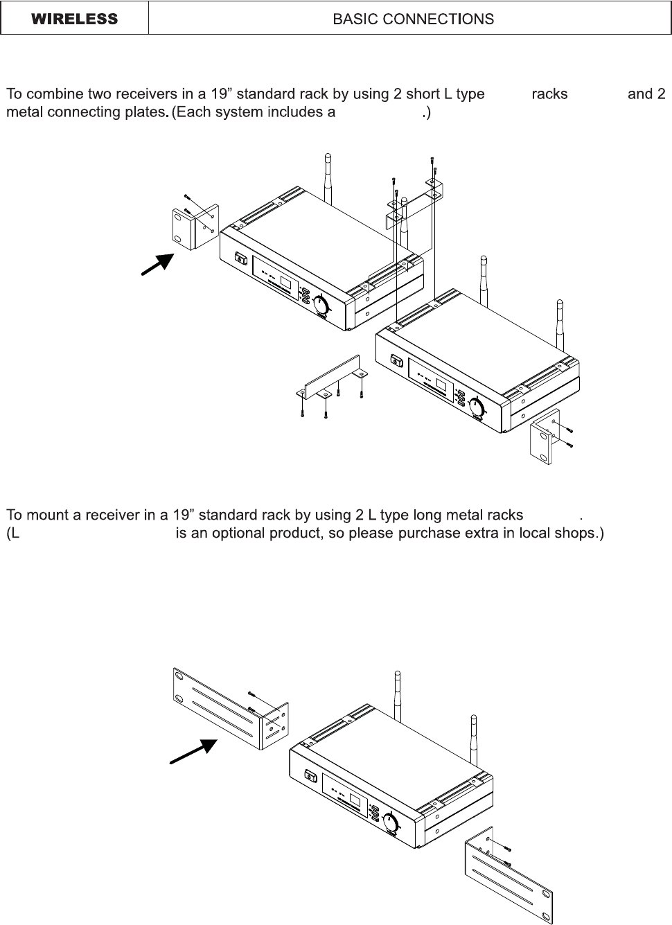
metal
short L type
mounts
mounts
type long metal racks
5. Basic Connections
6
13
whether is set too high or too low.
SPECIFICATION
6
14
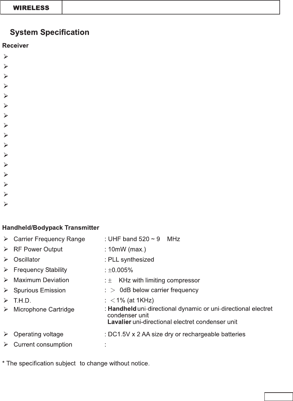
Carrier Frequency Range
Oscillator
Modulation
Frequency Stability
S/N ratio
Image and Spurious Rejection
Receiving Sensitivity
Selectivity
AF Response
T.H.D.
IF Frequency
Dynamic Range
Tone Signal
Audio Output
Power Supply
Current Consumption
: UHF 520 - 930MHz
: PLL Synthesized
: FM
: ±0.005%
: ɧ
: 80 dB minimum
: ɧ50dB
: 80Hz to 16KHz
: ɦ1% (at 1KHz)
: 1st: 243.95MHz 2nd:10.7MHz
: ɧ96dB
: 32.768KHz
: Balanced and unbalanced audio outputs
: About 200mA
30
7.
120mA ± 10mA
20
440-0093-7