Contents
- 1. User Manual Addendum
- 2. User Manual part 1
- 3. User Manual part 2
User Manual part 1
OPERATOR’S MANUAL
Rad-87™
Pulse CO-Oximeter

OPERATOR’S MANUAL
Rad-87™
Pulse CO-Oximeter
Rad-87 Pulse CO-Oximeter Operator’s Manual i
The Rad-87 Operating Instructions provide the necessary information for proper operation of all models of the
Rad-87 device. General knowledge of pulse CO-Oximetry and an understanding of the features and functions of the
Rad-87 are a prerequisite for its proper use. Do not operate the Rad-87 without completely reading and understanding
the instructions in this manual.
NOTICE:
Purchase or possession of this device does not carry any express or implied license to use this device with
replacement parts which would, alone or in combination with this device, fall within the scope of one of the patents
relating to this device.
CAUTION:
Federal law (U.S.) restricts this device to sale by or on the order of a physician.
Masimo Corporation
40 Parker
Irvine, CA 92618
USA
Tel.: 949-297-7000
Fax.: 949-297-7001
www.masimo.com
EU Authorized Representative for Masimo Corporation:
EC REP
MDSS GmbH
Schiffgraben 41
30175 Hannover, Germany
Tel.: +49-511-62 62 86 30
Fax.: +49-511-62 62 86 33
3149433
CONFORMS TO UL STD 60601-1, UL STD 763
UL STD 963 AND NSF STD 12;
CERTIFIED TO CAN/CSA STD C22.2 NO. 601.1
Covered by one or more of the following U.S. Patents: RE38,492, RE38,476, 7,221,971, 7,215,986, 7,215,984,
7,186,966, 6,979,812, 6,861,639, 6,850,787, 6,826,419, 6,816,741, 6,745,060, 6,699,194, 6,684,090, 6,654,624,
6,650,917, 6,643,530, 6,606,511, 6,515,273, 6,501,975, 6,463,311, 6,430,525, 6,388,240, 6,360,114, 6,263,222,
6,236,872, 6,229,856, 6,157,850, 6,067,462, 6,011,986, 6,002,952, 5,919,134, 5,769,785, 5,758,644, 5,685,299,
5,632,272, 5,490,505, 5,482,036, international equivalents, or one or more of the patents referenced at www.masimo.
com/patents.htm. Other patents pending.
© 2008 Masimo Corporation. Masimo, Discrete Saturation Transform, DST, DCI, Signal Extraction Technology, SET,
Radical, , Signal IQ, SIQ, FastSat, LNOP and LNCS are federally registered trademarks of Masimo Corporation.
Rainbow and SpCO are federally registered trademarks of Masimo Laboratories.
Rad-87, Pleth Variability Index, PVI, Patient SafetyNet, RadNet, LNOPv and APOD are trademarks of Masimo
Corporation. Rainbow SET, SpMet, SpHb, SpOC, Pulse CO-Oximeter and Signal Extraction Pulse CO-Oximeter
are trademarks of Masimo Laboratories.

Rad-87 Pulse CO-Oximeter Operator’s Manualii
SAFETY INFORMATION, WARNINGS, CAUTIONS AND NOTES
The Rad-87 Pulse CO-Oximeter is designed to minimize the possibility of hazards from errors in the software
program by following sound engineering design processes, Risk Analysis and Software Validation.
■ Explosion hazard. Do not use the Rad-87 in the presence of fl ammable anesthetics or other fl ammable
substance in combination with air, oxygen-enriched environments, or nitrous oxide.
■ High intensity extreme lights (including pulsating strobe lights) directed on the sensor, may not allow
the Pulse CO-Oximeter to obtain readings.
■ The Rad-87 is NOT intended for use as an apnea monitor.
■ The Pulse CO-Oximeter should be considered an early warning device. As a trend towards patient
hypoxemia is indicated, blood samples should be analyzed by laboratory instruments to completely
understand the patient’s condition.
■ Pulse rate measurement is based on the optical detection of a peripheral flow pulse and therefore
may not detect certain arrhythmias. The pulse oximeter should not be used as a replacement or
substitute for ECG based arrhythmia analysis.
■ The Rad-87 is to be operated by qualifi ed personnel only. This manual, accessory directions for use,
all precautionary information, and specifi cations should be read before use.
■ Electric shock hazard. Do not open the Rad-87 device. Only a qualifi ed operator may perform
maintenance procedures specifi cally described in this manual. Refer servicing to Masimo for repair of
this equipment.
■ As with all medical equipment, carefully route patient cabling to reduce the possibility of patient
entanglement or strangulation.
■ Do not place the Rad-87 or accessories in any position that might cause it to fall on the patient. Do not
lift the Rad-87 by the power cord or any other cable.
■ Interfering Substances: Dyes, or any substance containing dyes, that change usual blood pigmentation
may cause erroneous readings.
■ SpO2 is empirically calibrated to functional arterial oxygen saturation in healthy adult volunteers with
normal levels of carboxyhemoglobin (COHb) and methemoglobin (MetHb). A pulse oximeter can
not measure elevated levels of COHb or MetHb. Increases in either COHb or MetHb will affect the
accuracy of the SpO2 measurement.
■ For increased COHb: COHb levels above normal tend to increase the level of SpO2. The level
of increase is approximately equal to the amount of COHb that is present. NOTE: High levels of
COHb may occur with a seemingly normal SpO2. When elevated levels of COHb are suspected,
laboratory analysis (CO-Oximetry) of a blood sample should be performed.
NOTE: High levels of COHb may occur with a seemingly normal SpO2. When elevated levels of
COHb are suspected, laboratory analysis (CO-Oximetry) of a blood sample should be performed.
■ For increased MetHb: the SpO2 may be decreased by levels of MetHb of up to approximately 10%
to 15%. At higher levels of MetHb, the SpO2 may tend to read in the low to mid 80s. When elevated
levels of MetHb are suspected, laboratory analysis (CO-Oximetry) of a blood sample should be
performed.
■ Elevated levels of Methemoglobin (MetHb) will lead to inaccurate SpO2 and SpCO
measurements.
■ Elevated levels of Carboxyhemoglobin (COHb) will lead to inaccurate SpO2 measurements.
■ Elevated levels of Total Bilirubin may lead to inaccurate SpO2, SpMet, SpCO, SpHb and SpOC
measurements.
■ Motion artifact may lead to inaccurate SpMet, SpCO, SpHb and SpOC measurements.

Rad-87 Pulse CO-Oximeter Operator’s Manual iii
■ Very low arterial Oxygen Saturation (SpO2) levels may cause inaccurate SpCO and SpMet
measurements.
■ Severe anemia may cause erroneous SpO2 readings.
■
Hemoglobin synthesis disorders may cause erroneous SpHb readings.
■ Do not use the Rad-87 or sensors during magnetic resonance imaging (MRI) scanning. Induced
current could potentially cause burns. The Rad-87 may affect the MRI image and the MRI device may
affect the accuracy of the Pulse CO-Oximetry parameters and measurements.
■ If using Rad-87 during full body radiation, keep the sensor out of the radiation fi eld. If the sensor is
exposed to the radiation, the reading might be inaccurate or the device might read zero for the duration
of the active irradiation period.
■ For home use, ensure that the Rad-87’s alarm can be heard from other rooms in the house especially
when noisy appliances such as vacuum cleaners, dishwashers, clothes dryers, televisions, or radios
are operating.
■ Always remove the sensor from the patient and completely disconnect the patient from the Rad-87
before bathing the patient.
■ Additional information specific to Masimo sensors including information about parameter/measurement
performance during motion and low perfusion, may be found in the sensor's Directions For Use
(DFU).
■ Do not place the Rad-87 where the controls can be changed by the patient.
■ Do not place the Rad-87's face against a surface. This will cause the alarm to be muffl ed.
■ Do not place the Rad-87 on electrical equipment that may affect the Pulse CO-Oximeter, preventing it
from working properly.
■ Do not expose the Rad-87 to excessive moisture such as direct exposure to rain. Excessive moisture
can cause the device to perform inaccurately or fail.
■ Do not place containers with liquids on or near the Rad-87. Liquids spilled on the device may cause it
to perform inaccurately or fail.
■ If the Rad-87 fails any part of the setup procedures or leakage tests, remove the device from operation
until qualifi ed service personnel have corrected the situation.
■ Patient Safety - If a sensor is damaged in any way, discontinue use immediately.
■ Disposal of product - Comply with local laws in the disposal of the device and/or its accessories.
■ The Rad-87 can be used during defi brillation, but the readings may be inaccurate for up to 20
seconds.
■ This equipment has been tested and found to comply with the limits for medical devices to the
EN 60601-1-2: 2002, Medical Device Directive 93/42/EEC and Class B digital device, Part 15,
FCC Rules/USA. These limits are designed to provide reasonable protection against harmful
interference in a typical medical installation.
SAFETY INFORMATION, WARNINGS, CAUTIONS AND NOTES (CONTINUED)

Rad-87 Pulse CO-Oximeter Operator’s Manualiv
■ This equipment generates, uses and can radiate radio frequency energy and, if not installed
and used in accordance with the instructions, may cause harmful interference to other devices
in the vicinity. However, there is no guarantee that interference will not occur in a particular
installation. If this equipment does cause harmful interference to other devices, which can be
determined by turning the equipment off and on, the user is encouraged to try to correct the
interference by one or more of the following measures:
■ Reorient or relocate the receiving device.
■ Increase the separation between the equipment.
■ Connect the equipment into an outlet on a circuit different from that to which the other
device(s) are connected.
■ Consult the manufacturer for help.
■ In order to connect wirelessly to a compatible interface system like Patient SafetyNet, the
Rad-87 should be placed in an environment free from RF shielding, which could hinder
wireless reception.
■ To minimize radio interference, other electrical equipment that emits RF transmissions should
not be in close proximity to the RAD-87.
■ Changes or modifications to the wireless radio feature whether intentional or unintentional are
prohibited without written approval from Masimo Corporation.
■ The Rad-87 (device with optional radio) wirelessly transmits real-time sensor connectivity status,
indicating a connect and/or disconnect state. If the device is in a failure mode then the radio power
is disabled and an error message is indicated on the device display. The device does not have a
powered state where no information is transmitted.
■ In accordance with FCC requirements, the Rad-87 (device with optional radio) must be placed
greater then 20 cm from the patient's head.
■ In accordance with FCC requirements, radio accessories on the Rad-87 (device with optional
radio) cannot be attached directly to the patient using any accessory containing metal
components.
■ In accordance with international telecommunication requirements, the frequency band of
5,150 MHz to 5,250 MHz is only for indoor usage to reduce potential for harmful interference
to co-channel mobile satellite systems.
■ The battery should be adequately charged to ensure backup power in case of AC power
disruption.
■ A functional tester cannot be utilized to assess the accuracy of the Pulse CO-Oximeter or any
sensors.
■ To ensure safety, avoid stacking multiple devices or placing anything on the device during
operation.
■ Ensure the speaker is not covered or the device is placed face-down on bedding or other
sound absorbing surface.
■ To protect against injury from electric shock, follow the directions below:
■ Avoid placing the device on surfaces with visible liquid spills.
■ Do not soak or immerse the device in liquids.
■ Always turn off and disconnect the power cord from the AC power supply before cleaning
the device.
■ Use cleaning solutions sparingly.
SAFETY INFORMATION, WARNINGS, CAUTIONS AND NOTES (CONTINUED)

Rad-87 Pulse CO-Oximeter Operator’s Manual v
SECTION 1 - OVERVIEW
About This Manual . . . . . . . . . . . . . . . . . . . . . . . . . . . . . . . . . . . . . . . . . . . . . . . . . . . . . . 1-1
Warnings, Cautions and Notes. . . . . . . . . . . . . . . . . . . . . . . . . . . . . . . . . . . . . . . . . . . . . 1-2
Product Description . . . . . . . . . . . . . . . . . . . . . . . . . . . . . . . . . . . . . . . . . . . . . . . . . . . . . 1-3
Features . . . . . . . . . . . . . . . . . . . . . . . . . . . . . . . . . . . . . . . . . . . . . . . . . . . . . . . . 1-3
Optional Features . . . . . . . . . . . . . . . . . . . . . . . . . . . . . . . . . . . . . . . . . . . . . . . . . 1-3
Indications for Use. . . . . . . . . . . . . . . . . . . . . . . . . . . . . . . . . . . . . . . . . . . . . . . . . 1-4
Pulse CO-Oximetry . . . . . . . . . . . . . . . . . . . . . . . . . . . . . . . . . . . . . . . . . . . . . . . . . . . . . 1-4
SpO2 General Description . . . . . . . . . . . . . . . . . . . . . . . . . . . . . . . . . . . . . . . . . . 1-4
SpCO General Description . . . . . . . . . . . . . . . . . . . . . . . . . . . . . . . . . . . . . . . . . . 1-4
SpMet General Description . . . . . . . . . . . . . . . . . . . . . . . . . . . . . . . . . . . . . . . . . . 1-5
SpHb General Description . . . . . . . . . . . . . . . . . . . . . . . . . . . . . . . . . . . . . . . . . . 1-5
Total Arterial Oxygen Content (SpOC) General Description. . . . . . . . . . . . . . . . . 1-5
Principle of Operation . . . . . . . . . . . . . . . . . . . . . . . . . . . . . . . . . . . . . . . . . . . . . . 1-6
Functional Saturation . . . . . . . . . . . . . . . . . . . . . . . . . . . . . . . . . . . . . . . . . . . . . . 1-7
Rad-87 vs. Drawn Whole Blood Measurements . . . . . . . . . . . . . . . . . . . . . . . . . . 1-7
Masimo SET Signal Extraction Technology for SpO2 Measurements . . . . . . . . . 1-7
SpMet, SpCO, and SpHb and SpOC Measurements During Patient Motion . . . . 1-7
Fastat . . . . . . . . . . . . . . . . . . . . . . . . . . . . . . . . . . . . . . . . . . . . . . . . . . . . . . . . . . 1-7
Masimo Rainbow SET Parallel Engines . . . . . . . . . . . . . . . . . . . . . . . . . . . . . . . . 1-8
Masimo SET DST® . . . . . . . . . . . . . . . . . . . . . . . . . . . . . . . . . . . . . . 1-8
SECTION 2 - SYSTEM DESCRIPTION
Introduction. . . . . . . . . . . . . . . . . . . . . . . . . . . . . . . . . . . . . . . . . . . . . . . . . . . . . . . . . . . . 2-1
Rad-87 Front Panel Controls . . . . . . . . . . . . . . . . . . . . . . . . . . . . . . . . . . . . . . . . . . . . . . 2-2
Rad-87 Rear Panel. . . . . . . . . . . . . . . . . . . . . . . . . . . . . . . . . . . . . . . . . . . . . . . . . . . . . . 2-6
Symbols . . . . . . . . . . . . . . . . . . . . . . . . . . . . . . . . . . . . . . . . . . . . . . . . . . . . . . . . . . . . . . 2-7
LCD Display . . . . . . . . . . . . . . . . . . . . . . . . . . . . . . . . . . . . . . . . . . . . . . . . . . . . . . . . . . . 2-8
SECTION 3 - SETUP
Introduction. . . . . . . . . . . . . . . . . . . . . . . . . . . . . . . . . . . . . . . . . . . . . . . . . . . . . . . . . . . . 3-1
Unpacking and Inspection . . . . . . . . . . . . . . . . . . . . . . . . . . . . . . . . . . . . . . . . . . . . . . . . 3-1
Preparation for Monitoring . . . . . . . . . . . . . . . . . . . . . . . . . . . . . . . . . . . . . . . . . . . . . . . . 3-1
Rad-87 Power Requirements . . . . . . . . . . . . . . . . . . . . . . . . . . . . . . . . . . . . . . . . 3-1
Initial Battery Charging . . . . . . . . . . . . . . . . . . . . . . . . . . . . . . . . . . . . . . . . . . . . . 3-2
Initial Installation . . . . . . . . . . . . . . . . . . . . . . . . . . . . . . . . . . . . . . . . . . . . . . . . . . 3-2
SECTION 4 - OPERATION
Introduction. . . . . . . . . . . . . . . . . . . . . . . . . . . . . . . . . . . . . . . . . . . . . . . . . . . . . . . . . . . . 4-1
Basic operation. . . . . . . . . . . . . . . . . . . . . . . . . . . . . . . . . . . . . . . . . . . . . . . . . . . . . . . . . 4-1
General Setup and Use. . . . . . . . . . . . . . . . . . . . . . . . . . . . . . . . . . . . . . . . . . . . . 4-1
Default Settings . . . . . . . . . . . . . . . . . . . . . . . . . . . . . . . . . . . . . . . . . . . . . . . . . . . 4-3
Factory Default and User Configurable Settings. . . . . . . . . . . . . . . . . . . . . . . . . . 4-4
Successful Monitoring . . . . . . . . . . . . . . . . . . . . . . . . . . . . . . . . . . . . . . . . . . . . . . . . . . . 4-4
Masimo Pulse CO-Oximetry Sensors . . . . . . . . . . . . . . . . . . . . . . . . . . . . . . . . . . . . . . . 4-4
Numeric Display - SpO2 . . . . . . . . . . . . . . . . . . . . . . . . . . . . . . . . . . . . . . . . . . . . . . . . . . . . . . 4-5
Numeric Display - Pulse Rate . . . . . . . . . . . . . . . . . . . . . . . . . . . . . . . . . . . . . . . . 4-5
Numeric Display - SpCO . . . . . . . . . . . . . . . . . . . . . . . . . . . . . . . . . . . . . . . . . . . . 4-5
Numeric Display - SpMet . . . . . . . . . . . . . . . . . . . . . . . . . . . . . . . . . . . . . . . . . . . 4-5
Numeric Display - SpHb . . . . . . . . . . . . . . . . . . . . . . . . . . . . . . . . . . . . . . . . . . . . 4-6
table of contents

Rad-87 Pulse CO-Oximeter Operator’s Manualvi
table of contents
SECTION 4 - OPERATION (CONTINUED)
Numeric Display - SpOC . . . . . . . . . . . . . . . . . . . . . . . . . . . . . . . . . . . . . . . . . . . . 4-6
Numeric Display - PI . . . . . . . . . . . . . . . . . . . . . . . . . . . . . . . . . . . . . . . . . . . . . . . 4-6
Pleth Variability Index (PVI). . . . . . . . . . . . . . . . . . . . . . . . . . . . . . . . . . . . . . . . . . 4-7
Low Perfusion . . . . . . . . . . . . . . . . . . . . . . . . . . . . . . . . . . . . . . . . . . . . . . . . . . . . 4-7
Signal SIQ . . . . . . . . . . . . . . . . . . . . . . . . . . . . . . . . . . . . . . . . . . . . . . . . . . . . . . . 4-7
Sensor Placement . . . . . . . . . . . . . . . . . . . . . . . . . . . . . . . . . . . . . . . . . . . . . . . . . 4-8
Sensitivity . . . . . . . . . . . . . . . . . . . . . . . . . . . . . . . . . . . . . . . . . . . . . . . . . . . . . . . 4-9
Low Battery Audible Alarm . . . . . . . . . . . . . . . . . . . . . . . . . . . . . . . . . . . . . . . . . . 4-9
Normal Patient Monitoring . . . . . . . . . . . . . . . . . . . . . . . . . . . . . . . . . . . . . . . . . . . . . . . . 4-9
Paramater/Measurement Selection . . . . . . . . . . . . . . . . . . . . . . . . . . . . . . . . . . . 4-11
Setup Menu . . . . . . . . . . . . . . . . . . . . . . . . . . . . . . . . . . . . . . . . . . . . . . . . . . . . . 4-12
Menu Navigation . . . . . . . . . . . . . . . . . . . . . . . . . . . . . . . . . . . . . . . . . . . . . . . . . 4-12
Setup Menu Level 1 . . . . . . . . . . . . . . . . . . . . . . . . . . . . . . . . . . . . . . . . . . . . . . . . . . . . 4-13
Parameter/Measurement Alarm Limits - Screen 1 . . . . . . . . . . . . . . . . . . . . . . . 4-13
Parameter/Measurement Alarm Limits - Screen 2 . . . . . . . . . . . . . . . . . . . . . . . 4-14
Parameter/Measurement Alarm Limits - Screen 3 . . . . . . . . . . . . . . . . . . . . . . . 4-15
LED Brightness . . . . . . . . . . . . . . . . . . . . . . . . . . . . . . . . . . . . . . . . . . . . . . . . . . 4-15
Sensitivity . . . . . . . . . . . . . . . . . . . . . . . . . . . . . . . . . . . . . . . . . . . . . . . . . . . . . . 4-16
Setup Menu Level 2 . . . . . . . . . . . . . . . . . . . . . . . . . . . . . . . . . . . . . . . . . . . . . . . . . . . . 4-17
Alarm Volume . . . . . . . . . . . . . . . . . . . . . . . . . . . . . . . . . . . . . . . . . . . . . . . . . . . 4-17
Alarm Silence . . . . . . . . . . . . . . . . . . . . . . . . . . . . . . . . . . . . . . . . . . . . . . . . . . . 4-17
Alarm Delay. . . . . . . . . . . . . . . . . . . . . . . . . . . . . . . . . . . . . . . . . . . . . . . . . . . . . 4-18
Clear Trend . . . . . . . . . . . . . . . . . . . . . . . . . . . . . . . . . . . . . . . . . . . . . . . . . . . . . 4-18
Button Volume . . . . . . . . . . . . . . . . . . . . . . . . . . . . . . . . . . . . . . . . . . . . . . . . . . . 4-19
FastSat . . . . . . . . . . . . . . . . . . . . . . . . . . . . . . . . . . . . . . . . . . . . . . . . . . . . . . . . 4-19
Trend Setup and Use . . . . . . . . . . . . . . . . . . . . . . . . . . . . . . . . . . . . . . . . . . . . . . . . . . . 4-19
Introduction . . . . . . . . . . . . . . . . . . . . . . . . . . . . . . . . . . . . . . . . . . . . . . . . . . . . . 4-19
Trend Utility Installation . . . . . . . . . . . . . . . . . . . . . . . . . . . . . . . . . . . . . . . . . . . . 4-19
Trendcom Utility Operation . . . . . . . . . . . . . . . . . . . . . . . . . . . . . . . . . . . . . . . . . 4-20
Erasing Trend Memory . . . . . . . . . . . . . . . . . . . . . . . . . . . . . . . . . . . . . . . . . . . . 4-20
Trend Data Format . . . . . . . . . . . . . . . . . . . . . . . . . . . . . . . . . . . . . . . . . . . . . . . 4-21
Sample Trend Output. . . . . . . . . . . . . . . . . . . . . . . . . . . . . . . . . . . . . . . . . . . . . . 4-21
Setup Menu Level 3 . . . . . . . . . . . . . . . . . . . . . . . . . . . . . . . . . . . . . . . . . . . . . . . . . . . . 4-22
Averaging Time . . . . . . . . . . . . . . . . . . . . . . . . . . . . . . . . . . . . . . . . . . . . . . . . . . 4-22
Rapid Desat Limit . . . . . . . . . . . . . . . . . . . . . . . . . . . . . . . . . . . . . . . . . . . . . . . . 4-23
Alarm On/Off . . . . . . . . . . . . . . . . . . . . . . . . . . . . . . . . . . . . . . . . . . . . . . . . . . . . 4-23
Out Put Data . . . . . . . . . . . . . . . . . . . . . . . . . . . . . . . . . . . . . . . . . . . . . . . . . . . . 4-24
Default Settings . . . . . . . . . . . . . . . . . . . . . . . . . . . . . . . . . . . . . . . . . . . . . . . . . . 4-24
Device Profile Setup and Use . . . . . . . . . . . . . . . . . . . . . . . . . . . . . . . . . . . . . . 4-25
PVI Bar On/Off . . . . . . . . . . . . . . . . . . . . . . . . . . . . . . . . . . . . . . . . . . . . . . . . . . 4-26
Smart Tone On/Off . . . . . . . . . . . . . . . . . . . . . . . . . . . . . . . . . . . . . . . . . . . . . . . 4-26
Year . . . . . . . . . . . . . . . . . . . . . . . . . . . . . . . . . . . . . . . . . . . . . . . . . . . . . . . . . . . 4-26
Month . . . . . . . . . . . . . . . . . . . . . . . . . . . . . . . . . . . . . . . . . . . . . . . . . . . . . . . . . 4-26
Day . . . . . . . . . . . . . . . . . . . . . . . . . . . . . . . . . . . . . . . . . . . . . . . . . . . . . . . . . . . 4-27
Hour. . . . . . . . . . . . . . . . . . . . . . . . . . . . . . . . . . . . . . . . . . . . . . . . . . . . . . . . . . . 4-27
Minute . . . . . . . . . . . . . . . . . . . . . . . . . . . . . . . . . . . . . . . . . . . . . . . . . . . . . . . . . 4-28
Software Version . . . . . . . . . . . . . . . . . . . . . . . . . . . . . . . . . . . . . . . . . . . . . . . . . 4-28
Serial Output . . . . . . . . . . . . . . . . . . . . . . . . . . . . . . . . . . . . . . . . . . . . . . . . . . . . . . . . . 4-29

Rad-87 Pulse CO-Oximeter Operator’s Manual vii
SECTION 4 - OPERATION - (CONTINUED)
Interface Alarms . . . . . . . . . . . . . . . . . . . . . . . . . . . . . . . . . . . . . . . . . . . . . . . . . 4-29
System Interfaces. . . . . . . . . . . . . . . . . . . . . . . . . . . . . . . . . . . . . . . . . . . . . . . . . . . . . . 4-29
Philips VueLink Set . . . . . . . . . . . . . . . . . . . . . . . . . . . . . . . . . . . . . . . . . . . . . . . 4-29
Radnet Setup . . . . . . . . . . . . . . . . . . . . . . . . . . . . . . . . . . . . . . . . . . . . . . . . . . . 4-30
Patient SafetyNet Setup . . . . . . . . . . . . . . . . . . . . . . . . . . . . . . . . . . . . . . . . . . . 4-30
Nurse Call . . . . . . . . . . . . . . . . . . . . . . . . . . . . . . . . . . . . . . . . . . . . . . . . . . . . . . 4-31
Polarity. . . . . . . . . . . . . . . . . . . . . . . . . . . . . . . . . . . . . . . . . . . . . . . . . . . . . . . . . 4-31
Line Frequency . . . . . . . . . . . . . . . . . . . . . . . . . . . . . . . . . . . . . . . . . . . . . . . . . . 4-31
Parameter/Measurement Select - Screen 1 . . . . . . . . . . . . . . . . . . . . . . . . . . . . 4-32
Parameter/Measurement Select - Screen 2 . . . . . . . . . . . . . . . . . . . . . . . . . . . . 4-32
Parameter/Measurement Select - Screen 3 . . . . . . . . . . . . . . . . . . . . . . . . . . . . 4-33
LCD Language . . . . . . . . . . . . . . . . . . . . . . . . . . . . . . . . . . . . . . . . . . . . . . . . . . 4-33
Set Mode . . . . . . . . . . . . . . . . . . . . . . . . . . . . . . . . . . . . . . . . . . . . . . . . . . . . . . . 4-33
Home Mode Operation . . . . . . . . . . . . . . . . . . . . . . . . . . . . . . . . . . . . . . . . . . . . . . . . . . 4-34
Sleep Mode Operation . . . . . . . . . . . . . . . . . . . . . . . . . . . . . . . . . . . . . . . . . . . . . . . . . . 4-34
Enable/Disable Radio . . . . . . . . . . . . . . . . . . . . . . . . . . . . . . . . . . . . . . . . . . . . . 4-34
LCD Display Function with Radio Configured and Enabled . . . . . . . . . . . . . . . . . . .4-35
SECTION 5 - ALARMS AND MESSAGES
Alarm Identification. . . . . . . . . . . . . . . . . . . . . . . . . . . . . . . . . . . . . . . . . . . . . . . . . . . . . . 5-1
Alarm Indication . . . . . . . . . . . . . . . . . . . . . . . . . . . . . . . . . . . . . . . . . . . . . . . . . . . . . . . . 5-1
Alarm Limits . . . . . . . . . . . . . . . . . . . . . . . . . . . . . . . . . . . . . . . . . . . . . . . . . . . . . . . . . . . 5-2
Alarm Limit: User Configurable Settings . . . . . . . . . . . . . . . . . . . . . . . . . . . . . . . . 5-2
Alarm Limit: Factory Default Settings . . . . . . . . . . . . . . . . . . . . . . . . . . . . . . . . . . 5-3
Single Alarm Features . . . . . . . . . . . . . . . . . . . . . . . . . . . . . . . . . . . . . . . . . . . . . . . . . . . 5-4
Multi-Parameter/Measurement Alarm Features . . . . . . . . . . . . . . . . . . . . . . . . . . . . . . . . 5-4
Alarm Priority for Display Screens . . . . . . . . . . . . . . . . . . . . . . . . . . . . . . . . . . . . 5-4
Alarm Silence . . . . . . . . . . . . . . . . . . . . . . . . . . . . . . . . . . . . . . . . . . . . . . . . . . . . . . . . . . 5-5
Alarm Bell . . . . . . . . . . . . . . . . . . . . . . . . . . . . . . . . . . . . . . . . . . . . . . . . . . . . . . . 5-5
System Status Light . . . . . . . . . . . . . . . . . . . . . . . . . . . . . . . . . . . . . . . . . . . . . . . 5-5
Alarm Mute . . . . . . . . . . . . . . . . . . . . . . . . . . . . . . . . . . . . . . . . . . . . . . . . . . . . . . . . . . . . 5-6
Messages . . . . . . . . . . . . . . . . . . . . . . . . . . . . . . . . . . . . . . . . . . . . . . . . . . . . . . . . . . . . . 5-7
SECTION 6 - TROUBLESHOOTING
Troubleshooting . . . . . . . . . . . . . . . . . . . . . . . . . . . . . . . . . . . . . . . . . . . . . . . . . . . . . . . . 6-1
SECTION 7 - SPECIFICATIONS
Rad-87 Specifications . . . . . . . . . . . . . . . . . . . . . . . . . . . . . . . . . . . . . . . . . . . . . . . . . . . 7-1
Performance . . . . . . . . . . . . . . . . . . . . . . . . . . . . . . . . . . . . . . . . . . . . . . . . . . . . . 7-1
Accuracy . . . . . . . . . . . . . . . . . . . . . . . . . . . . . . . . . . . . . . . . . . . . . . . . . . . . . . . . 7-1
Electrical . . . . . . . . . . . . . . . . . . . . . . . . . . . . . . . . . . . . . . . . . . . . . . . . . . . . . . . . 7-2
Environmental . . . . . . . . . . . . . . . . . . . . . . . . . . . . . . . . . . . . . . . . . . . . . . . . . . . . 7-2
Physical Characteristics . . . . . . . . . . . . . . . . . . . . . . . . . . . . . . . . . . . . . . . . . . . . 7-2
Serial Interface Specifications. . . . . . . . . . . . . . . . . . . . . . . . . . . . . . . . . . . . . . . . 7-4
Serial Interface Setup . . . . . . . . . . . . . . . . . . . . . . . . . . . . . . . . . . . . . . . . . . . . . . 7-4
Serial Printer Setup. . . . . . . . . . . . . . . . . . . . . . . . . . . . . . . . . . . . . . . . . . . . . . . . 7-5
Nurse Call Specifications . . . . . . . . . . . . . . . . . . . . . . . . . . . . . . . . . . . . . . . . . . . . . . . . . 7-5
Nurse Call . . . . . . . . . . . . . . . . . . . . . . . . . . . . . . . . . . . . . . . . . . . . . . . . . . . . . . . 7-5
table of contents

Rad-87 Pulse CO-Oximeter Operator’s Manualviii
SECTION 8 - SENSORS & PATIENT CABLES
Introduction. . . . . . . . . . . . . . . . . . . . . . . . . . . . . . . . . . . . . . . . . . . . . . . . . . . . . . . . . . . . 8-1
Selecting a Masimo SET Sensor . . . . . . . . . . . . . . . . . . . . . . . . . . . . . . . . . . . . . 8-1
Sensor Application Instructions. . . . . . . . . . . . . . . . . . . . . . . . . . . . . . . . . . . . . . . 8-1
Masimo Rainbow Sensors . . . . . . . . . . . . . . . . . . . . . . . . . . . . . . . . . . . . . . . . . . . . . . . . 8-2
Rainbow Reusable Sensors . . . . . . . . . . . . . . . . . . . . . . . . . . . . . . . . . . . . . . . . . 8-2
Rainbow Direct Connect Sensors . . . . . . . . . . . . . . . . . . . . . . . . . . . . . . . . . . . . . 8-2
Masimo SpO2 Sensors . . . . . . . . . . . . . . . . . . . . . . . . . . . . . . . . . . . . . . . . . . . . . . . . . . 8-3
Red Direct Connect Sensors . . . . . . . . . . . . . . . . . . . . . . . . . . . . . . . . . . . . . . . . 8-3
LNOP® Reusable Sensors . . . . . . . . . . . . . . . . . . . . . . . . . . . . . . . . . . . . . . . . . . 8-3
LNOP® Adhesive Sensors . . . . . . . . . . . . . . . . . . . . . . . . . . . . . . . . . . . . . . . . . . . 8-4
LNOPvTM Adhesive Sensors . . . . . . . . . . . . . . . . . . . . . . . . . . . . . . . . . . . . . . . . . . . . . 8-4
LNOP® Specialty Sensors . . . . . . . . . . . . . . . . . . . . . . . . . . . . . . . . . . . . . . . . . . . 8-4
LNCS® Reusable Sensors . . . . . . . . . . . . . . . . . . . . . . . . . . . . . . . . . . . . . . . . . . 8-4
LNCS® Adhesive Sensors . . . . . . . . . . . . . . . . . . . . . . . . . . . . . . . . . . . . . . . . . . 8-5
LNCS® Specialty Sensors . . . . . . . . . . . . . . . . . . . . . . . . . . . . . . . . . . . . . . . . . . 8-5
Sensor Accuracy . . . . . . . . . . . . . . . . . . . . . . . . . . . . . . . . . . . . . . . . . . . . . . . . . . . . . . . 8-6
Cleaning And Reuse Of Masimo Reusable Sensors and Cables . . . . . . . . . . . . . . . . . . 8-6
Reattachment of Single Use Adhesive Sensors . . . . . . . . . . . . . . . . . . . . . . . . . . . . . . . 8-6
SECTION 9 - SERVICE AND MAINTENANCE
Introduction. . . . . . . . . . . . . . . . . . . . . . . . . . . . . . . . . . . . . . . . . . . . . . . . . . . . . . . . . . . . 9-1
Cleaning . . . . . . . . . . . . . . . . . . . . . . . . . . . . . . . . . . . . . . . . . . . . . . . . . . . . . . . . . . . . . . 9-1
Battery Service and Performance Verification . . . . . . . . . . . . . . . . . . . . . . . . . . . . . . . . . 9-2
Service and Repair. . . . . . . . . . . . . . . . . . . . . . . . . . . . . . . . . . . . . . . . . . . . . . . . . . . . . . 9-4
Repair Policy . . . . . . . . . . . . . . . . . . . . . . . . . . . . . . . . . . . . . . . . . . . . . . . . . . . . . 9-4
Return Procedure . . . . . . . . . . . . . . . . . . . . . . . . . . . . . . . . . . . . . . . . . . . . . . . . . 9-4
Sales & End-user License Agreement . . . . . . . . . . . . . . . . . . . . . . . . . . . . . . . . . . . . . . . 9-5
Warranty . . . . . . . . . . . . . . . . . . . . . . . . . . . . . . . . . . . . . . . . . . . . . . . . . . . . . . . . . . . . . . 9-5
Exclusions . . . . . . . . . . . . . . . . . . . . . . . . . . . . . . . . . . . . . . . . . . . . . . . . . . . . . . . . . . . . 9-5
End-user License . . . . . . . . . . . . . . . . . . . . . . . . . . . . . . . . . . . . . . . . . . . . . . . . . . . . . . . 9-6
Restrictions. . . . . . . . . . . . . . . . . . . . . . . . . . . . . . . . . . . . . . . . . . . . . . . . . . . . . . . . . . . . 9-6
SECTION 10 - PART NUMBERS
Part Numbers . . . . . . . . . . . . . . . . . . . . . . . . . . . . . . . . . . . . . . . . . . . . . . . . . . . . . . . . . 10-1
table of contents

Rad-87 Pulse CO-Oximeter Operator’s Manual 1-1
1
overview
About This Manual
This manual explains how to set up and use the Rad-87 Pulse CO-Oximeter containing Masimo
Rainbow SET technology. Important safety information relating to general use of the Rad-87
appears before this introduction. Other important safety information is located throughout the
manual where appropriate.
Read the entire safety information section before you operate the monitor.
In addition to the safety section, this manual includes the following sections:
SECTION 1 OVERVIEW gives a general description of Rad-87 Pulse CO-Oximeter.
SECTION 2 SYSTEM DESCRIPTION describes the Rad-87 Pulse CO-Oximeter
system and its functions and features.
SECTION 3 SETUP describes how to setup the Rad-87 Pulse CO-Oximeter for use.
SECTION 4 OPERATION describes the operation of the Rad-87 Pulse CO-Oximeter
system.
SECTION 5 ALARMS AND MESSAGES describes the alarm system messages.
SECTION 6 TROUBLESHOOTING describes troubleshooting information.
SECTION 7 SPECIFICATIONS gives the detailed specifi cations of the Rad-87 Pulse
CO-Oximeter.
SECTION 8 SENSORS & PATIENT CABLES outlines how to use and care for Masimo
Rainbow SET technology sensors, Masimo Rainbow SET technology
patient cables, Masimo Red sensors and, Masimo Red PC cables.
SECTION 9 SERVICE AND MAINTENANCE describes how to maintain, service and
obtain repair for the Rad-87 Pulse CO-Oximeter.
SECTION 10 ACCESSORIES lists the available models of the Rad-87 Pulse
CO-Oximeter.

1-2 Rad-87 Pulse CO-Oximeter Operator’s Manual
1
Warnings, Cautions and Notes
Please read and follow any warnings, cautions and notes presented throughout this
manual. An explanation of these labels are as follows:
A WARNING is provided when actions may result in a serious outcome (i.e., injury,
serious adverse affect, death) to the patient or user. Look for text in a gray shaded box.
Sample of Warning:
WARNING: THIS IS A SAMPLE OF A WARNING STATEMENT.
A CAUTION is given when any special care is to be exercised by the patient or user to avoid injury
to the patient, damage to this device or damage to other property.
Sample of Caution:
CAUTION: THIS IS A SAMPLE OF A CAUTION STATEMENT.
A NOTE is provided when extra general information is applicable.
Sample of Note:
NOTE: This is a sample of a Note.
overview

Rad-87 Pulse CO-Oximeter Operator’s Manual 1-3
1
overview
Product Description
The Rad-87 Pulse CO-Oximeter Monitor is a noninvasive, arterial oxygen, carboxyhemoglobin and
methemoglobin saturation, total hemoglobin concentration, total arterial oxygen content and pulse rate
monitor. The Rad-87 features a multicolored LED display that continuously displays numeric values for
SpO2, SpCO®*, SpMet™*, SpHb™*, total arterial oxygen content (SpOC*), perfusion index (PI), pleth
variability index* (PVI) and pulse rate. It also provides bar graph displays for quick visual identifi cation of
Signal Identifi cation Quality (SIQ®), perfusion index and pleth variability index.
The Rad-87 is available in four models: vertical Rad-87, horizontal Rad-87, vertical Rad-87 with radio and
horizontal Rad-87 with radio.
FEATURES
These features are common to Rad-87 monitors:
■ Masimo SET is clinically proven to be the highest sensitivity and specifi city pulse oximeter
technology in the world.
■ Rainbow technology continuously and noninvasively measures arterial oxygen saturation (SpO2)
and pulse rate (BPM), as well as providing a reliable probe-off detection.
■ Perfusion Index (PI) with trending capability indicates arterial pulse signal strength during low
perfusion.
■ Accurate on cyanotic infants with congenital heart disease when used with an LNOP® Blue
Sensor.
■ Signal IQ® provides signal identifi cation and quality indication during excessive motion and low
signal to noise situations.
■ FastSat® tracks rapid changes in arterial O2 saturation with high fidelity.
■ Variable pitch provides tonal variance for every 1% change in saturation.
■ Remote alarming interface.
■ Up to 72 hours of trending. (See Section 4, Trends Setup and Use.)
■ Allows user to customize the default settings and set the device to retain these settings through a
power off/on cycle.
■ The LCD Display allows the user to view a scrolling marque of (installed) parameter/measurement
alarm limits, system information, and wireless radio communication (wireless radio model only).
OPTIONAL FEATURES
■ Rainbow technology uses 7+ wavelengths of light to continuously and noninvasively
measure carboxyhemoglobin (SpCO), methemoglobin (SpMet) and total hemoglobin
(SpHb), as well as providing a reliable probe-off detection.
■ Pleth Variability Index (PVI) may show changes that refl ect physiologic factors such as
vascular tone, circulating blood volume, and intrathoracic pressure excursions.1
■ Total arterial oxygen content (SpOC) provides a calculated measurement of the amount of
oxygen in arterial blood which may provide useful information for both oxygen dissolved in
plasma and combined with hemoglobin.
■ Provides a 802.11a/b/g wireless radio which interfaces with compatible systems (wireless radio
model only)
■ Ability to connect to Masimo Patient SafetyNet through a wireless network (wireless radio
model only).
1 The utility of PVI is unknown at this time and requires further clinical studies. Technical factors that may affect PVI
include probe malposition and patient motion.
*Optional features: SpCO, SpMet, SpHb, SpOC, PVI
1-4 Rad-87 Pulse CO-Oximeter Operator’s Manual
1overview
INDICATIONS FOR USE
The Rad-87 Pulse CO-Oximeter and accessories are indicated for the continuous, non-invasive
monitoring of functional oxygen saturation of arterial hemoglobin (SpO2), carboxyhemoglobin and
methemoglobin concentration expressed in percentage (SpCO and SpMet) and total hemoglobin
concentration expressed in grams per deciliter (SpHb).The Rad-87 Pulse CO-Oximeter and
accessories are indicated for use with adult, pediatric and neonatal patients during both motion and
no motion conditions, who are well or poorly perfused patients in hospitals, hospital-type facilities,
mobile and home environments.
Pulse CO-Oximetry
SpO2 GENERAL DESCRIPTION
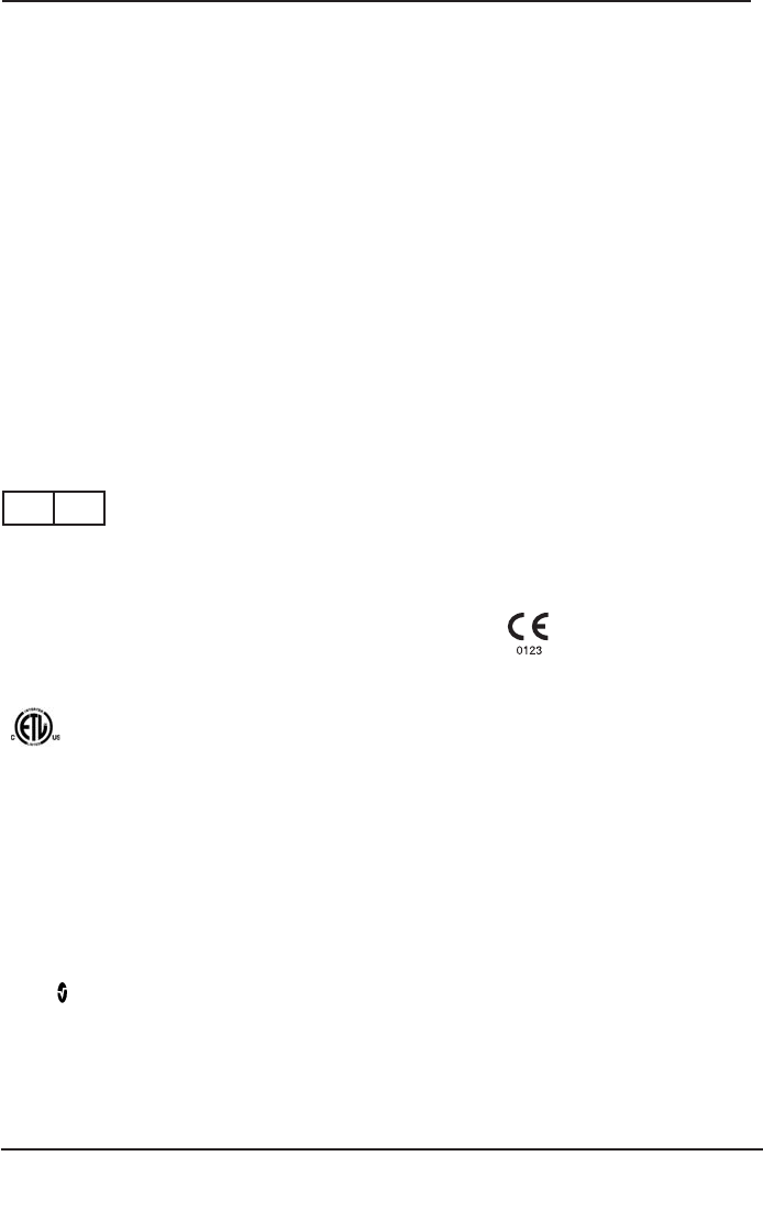
Pulse CO-Oximetry is a continuous and noninvasive method of measuring the level of arterial
oxygen saturation in blood. The measurement is taken by placing a sensor on a patient, usually
on the fi ngertip for adults and the hand or foot for neonates. The sensor is connected to the
Pulse CO-Oximetry instrument with a patient cable. The sensor collects signal data from the
patient and sends it to the instrument.
The following fi gure shows the general monitoring setup.
SpCO GENERAL DESCRIPTION
Pulse CO-Oximetry is a continuous and noninvasive method of measuring the levels of
carboxyhemoglobin concentration (SpCO) in arterial blood. It relies on the same basic principles
of pulse oximetry (spectrophotometry) to make its SpCO measurement. The measurement is
obtained by placing a sensor on a patient, usually on the fi ngertip for adults and the hand or foot
for infants. The sensor connects either directly to the Pulse CO-Oximetry instrument or through
an instrument patient cable. The sensor collects signal data from the patient and sends it to the
instrument. The instrument displays the calculated data as percentage value for the SpCO, which
refl ect blood levels of carbon monoxide bound to hemoglobin.
SpMet GENERAL DESCRIPTION
Pulse CO-Oximetry is a continuous and noninvasive method of measuring the levels of
methemoglobin concentration (SpMet) in arterial blood. It relies on the same basic principles
of pulse oximetry (spectrophotometry) to make its SpMet measurement. The measurement is
obtained by placing a sensor on a patient, usually on the fi ngertip for adults and the hand or foot
for infants. The sensor connects either directly to the Pulse CO-Oximetry instrument or through
an instrument patient cable. The sensor collects signal data from the patient and sends it to the
instrument. The instrument displays the calculated data as percentage value for the SpMet.
TOTAL HEMOGLOBIN (SpHb) GENERAL DESCRIPTION
1. Instrument
2. Patient Cable
3. Sensor
NORM
APODMAX
SENSITIVITY
MODE
rbc monitor
3
2
1
10.1
97
76

Rad-87 Pulse CO-Oximeter Operator’s Manual 1-5
1
overview
Pulse CO-Oximetry is a continuous and noninvasive method of measuring the levels of total hemoglobin
(SpHb) in arterial blood. It relies on the same principles of pulse oximetry to make the SpHb measurement.
The measurement is taken by a sensor capable of measuring SpHb, usually on the fingertip for adults
and pediatric patients. The sensor connects directly to the Pulse CO-Oximeter or with a patient cable. The
sensor collects signal data from the patient and sends it to the instrument. The instrument displays the
calculated data as measurement of total hemoglobin concentration. The Rad-87 can be configured to be
a combined SpO2 monitor with other available parameters/measurements.
TOTAL ARTERIAL OXYGEN CONTENT (CaO2) GENERAL DESCRIPTION2
Oxygen (O2) is carried in the blood in two forms, either dissolved in plasma or combined with
hemoglobin. The amount of oxygen in the arterial blood is termed the oxygen content (CaO2) and
is measured in units of ml O2/dl blood. One gram of hemoglobin (Hb) can carry 1.34 ml of oxygen,
whereas 100 ml of blood plasma may carry approximately 0.3 ml of oxygen. The oxygen content is
determined mathematically as:
CaO2 = 1.34 (ml O2/g Hb) x Hb (g/dl) x HbO2 + PaO2 (mm Hg) x (0.3 ml O2/ 100 mm Hg/dl)
Where HbO2 is the fractional arterial oxygen saturation and PaO2 is the partial pressure of
arterial oxygen.
For typical PaO2 values, the second part of the above equation [PaO2 (mm Hg) x (0.3 ml O2/ 100 mm
Hg/dl] is approximately 0.3 ml/dl. Furthermore, for typical carboxyhemoglobin and methemoglobin
levels, the functional saturation (SpO2) as measured by a pulse oximeter is given by:
SpO2 = 1.02 x HbO2
2 Martin, Laurence. All You Really Need to Know to Interpret Arterial Blood Gases, Second Edition.
New York: Lippincott Williams & Wilkins, 1999.
SpOC General Description (Pulse CO-Oximetry)
The above approximations result in the following reduced equation for oxygen content via the
Pulse CO-Oximeter:
SpOC (ml/dl*) = 1.31 (ml O2/g Hb) x SpHb (g/dl) x SpO2 + 0.3 ml/dl
*When ml O2/g Hb is multiplied by g/dl of Hb, the gram unit in the denominator of ml/g cancels
the gram unit in the numerator of g/dl resulting in ml/dl (ml of oxygen in one dl of blood) as the
unit of measure for SpOC.
1-6 Rad-87 Pulse CO-Oximeter Operator’s Manual
1overview
PRINCIPLE OF OPERATION
Pulse CO-Oximetry is governed by the following principles:
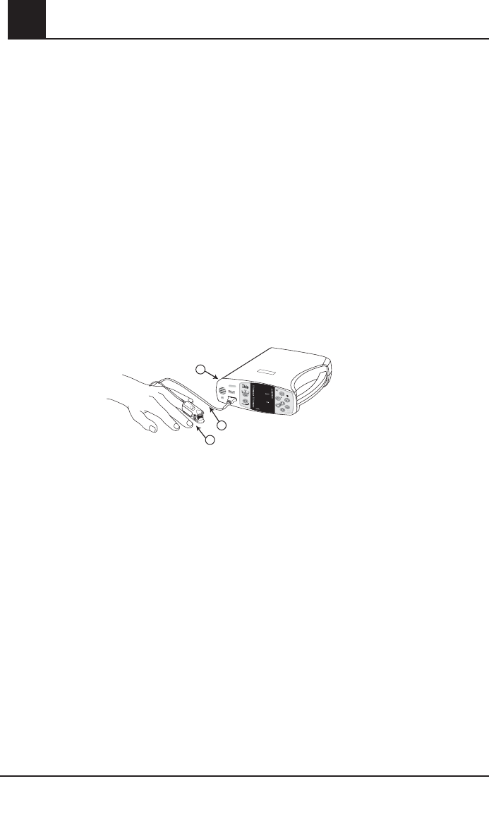
1. Oxyhemoglobin (oxygenated blood), deoxyhemoglobin (non-oxygenated blood),
carboxyhemoglobin (blood with carbon monoxide content), methemoglobin (blood with oxidized
hemoglobin) and blood plasma constituents differ in their absorption of visible and infrared light
(using spectrophotometry, see fi gure below).
Carboxyhemoglobin
Oxyhemoglobin
Methemoglobin
Deoxyhemoglobin
Absorption Spectra
Plasma
Absorption (1/mm)
0
0.5
600 800
1.0
1.5
2.0
2.5
3.0
3.5
4.0
1000 1200 1400 1600
Wavelength (nm)
2. The amount of arterial blood in tissue changes with your pulse (photoplethysography). Therefore,
the amount of light absorbed by the varying quantities of arterial blood changes as well.
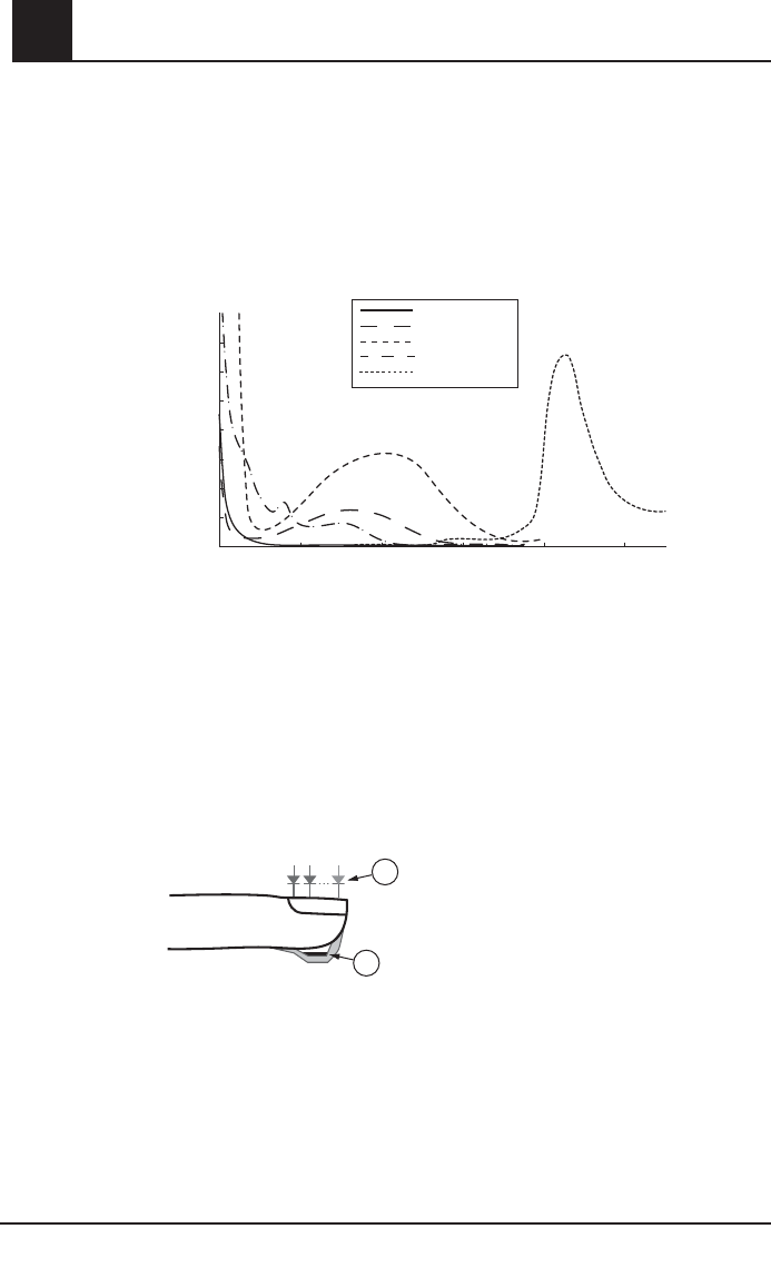
The Rad-87 Pulse CO-Oximeter uses a multi-wavelength sensor to distinguish between
oxygenated blood, deoxygenated blood, blood with carbon monoxide, oxidized blood and blood
plasma. The Rad-87 utilizes a sensor with various light-emitting diodes (LEDs) that pass light
through the site to a photodiode (detector). See fi gure below. Signal data is obtained by passing
various visible and infrared lights (LED’s, 500 to 1400nm) through a capillary bed (for example,
a fi ngertip, a hand, a foot) and measuring changes in light absorption during the blood pulsatile
cycle. This information may be useful to clinicians. The maximum radiant power of the strongest
light is rated at ≤ 25mW. The detector receives the light, converts it into an electronic signal and
sends it to the Rad-87 for calculation.
Once the Rad-87 receives the signal from the sensor, it utilizes Masimo Rainbow SET signal
extraction technology to calculate the patient’s functional arterial oxygen saturation, blood levels
of carboxyhemoglobin (SpCO), methemoglobin (SpMet) and pulse rate. The SpCO and SpMet
measurements rely on a multiwavelength calibration equation to quantify the percentage of carbon
monoxide and methemoglobin in arterial blood. In an ambient temperature of 35º C the maximum
skin surface temperature has been measured at less than 106º F (41º C), verifi ed by Masimo
sensor skin temperature test procedure.
2
1
1. Light Emitting Diodes (LEDs)
( 7+ wavelengths )
2. Detector

Rad-87 Pulse CO-Oximeter Operator’s Manual 1-7
1
overview
FUNCTIONAL SATURATION
The Rad-87 is calibrated to measure and display functional saturation (SpO2): the amount of oxyhemoglobin
expressed as a percentage of the hemoglobin that is available to transport oxygen.
RAD-87 vs. DRAWN WHOLE BLOOD MEASUREMENTS
When SpO2, SpCO, SpMet and SpHb measurements obtained from the Rad-87 (noninvasive) are
compared to drawn whole blood (invasive) measurements by blood gas and/or laboratory CO-Oximetry
methods, caution should be taken when evaluating and interpreting the results. The blood gas and/or
laboratory CO-Oximetry measurements may differ from the SpO2, SpCO, SpMet and SpHb measurements
of the Rad-87 Pulse CO-Oximeter. In the case of SpO2, different results are usually obtained from the
arterial blood gas sample if the calculated measurement is not appropriately corrected for the effects of
variables that shift the relationship between the partial pressure of oxygen (PO2) and saturation, such
as: pH, temperature, the partial pressure of carbon dioxide (PCO2), 2,3-DPG, and fetal hemoglobin. In
the case of SpCO, different results are also expected if concentration of methemoglobin in the blood
gas sample is elevated. High levels of bilirubin may cause erroneous SpO2, SpMet, SpCO and SpHb
readings. As blood samples are usually taken over a period of 20 seconds (the time it takes to draw
the blood) a meaningful comparison can only be achieved if the oxygen saturation, carboxyhemoglobin
and methemoglobin concentration of the patient are stable and not changing over the period of time that
the blood gas sample is taken. Subsequently, blood gas and laboratory CO-Oximetry measurements of
SpO2, SpCO, SpMet and SpHb may vary with the rapid administration of fl uids and in procedures such
as dialysis. Additionally, drawn, whole-blood testing can be affected by sample handling methods and time
elapsed between blood draw and sample testing.
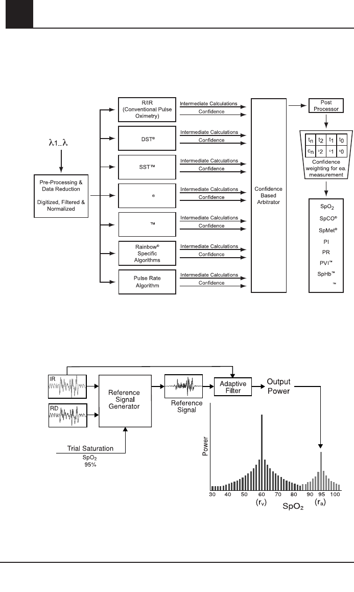
MASIMO SET SIGNAL EXTRACTION TECHNOLOGY FOR SpO2 MEASUREMENTS
Masimo Signal Extraction Technology’s signal processing differs from conventional pulse oximeters.
Conventional pulse oximeters assume that arterial blood is the only blood moving (pulsating) in the
measurement site. During patient motion, however, the venous blood also moves, causing conventional
pulse oximeters to read low values, because they cannot distinguish between the arterial and venous
blood movement (sometimes referred to as noise). Masimo SET pulse oximetry utilizes parallel engines
and adaptive digital fi ltering. Adaptive fi lters are powerful because they are able to adapt to the varying
physiologic signals and/or noise and separate them by looking at the whole signal and breaking it down to its
fundamental components. The Masimo SET signal processing algorithm, Discrete Saturation Transform®
(DST®) reliably identifi es the noise, isolates it and, using adaptive fi lters, cancels it. It then reports the true
arterial oxygen saturation for display on the monitor.
SpMet, SpCO, AND SpHb MEASUREMENTS DURING PATIENT MOTION
The Rad-87 displays measurements of SpCO, SpMet and SpHb during patient motion. However,
because of the changes in the physiological parameters such as blood volume, arterial-venous
coupling, etc. that occur during patient motion, the accuracy of such measurements may not be reliable
during excessive motion. When the Rad-87 does not have confidence in the value of a parameter due
to poor signal quality caused by excessive motion or other signal interference, the measurement for
the parameter will alternate with "---".
FASTSAT
FastSat enables rapid tracking of arterial oxygen saturation changes. Arterial oxygen saturation data
is averaged using pulse oximeter averaging algorithms to smooth the trend. When the Rad-87 is set
to FastSat “On”, the averaging algorithm evaluates all the saturation values providing an averaged
saturation value that is a better representation of the patient’s current oxygenation status. With FastSat,
the averaging time is dependent on the input signal.
1-8 Rad-87 Pulse CO-Oximeter Operator’s Manual
1
MASIMO RAINBOW SET PARALLEL ENGINES
MASIMO SET DST
This fi gure is for conceptual purposes only.
SpOC
12
FST
MST

Rad-87 Pulse CO-Oximeter Operator’s Manual 2-1
2
system description
Introduction
The Rad-87 Pulse CO-Oximeters are full featured devices designed for ease of operation. All pulse
CO-Oximetry measurement information, as well as device status data, is displayed on the front
panel of the device. All user input is handled by control buttons on the front panel. The sensor cable
connections are located on the left side of the front panel for the Rad-87 horizontal device and the
bottom of the front panel for the Rad-87 vertical device.
■ Rad-87 offers full Masimo SET technology in a small compact device
■ Rad-87 supports the full line of Masimo sensors and patient cables (see Section 8, Sensors
and Patient Cables)
■ Rad-87 supports standardization of sensors, and pulse CO-Oximetry technology throughout
the hospital
■ The LCD Display identifies system settings, monitoring modes, alarm limits and information
from Patient SafetyNet or Philips VueLink (when connected). The LCD is located on top of the
device (Horizontal) or on the left of the device (Vertical).
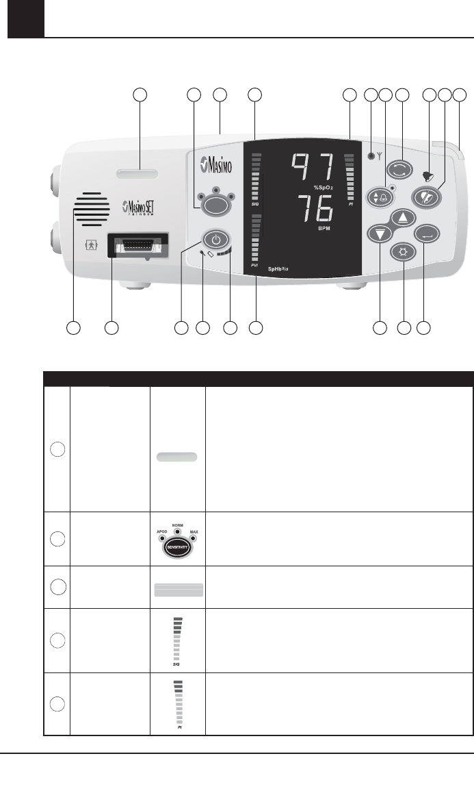
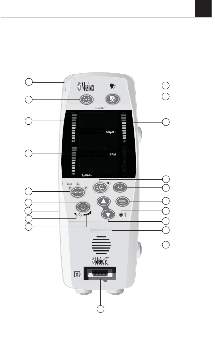
2-2 Rad-87 Pulse CO-Oximeter Operator’s Manual
2system description
CONTROL / INDICATOR DESCRIPTION
1
Device Profile
LED
The Device Profile LED illuminates when the device has been
set to user configured "default" settings. Upon power up, the
user configured default settings are retained and the Device
Profile LED remain lit.
When user configured default settings are active, any changes
to the default settings cause the Device Profile LED to turn
off until the device is returned to the user configured default
settings or powered off.
2
Sensitivity
Button/Indicator
Used to set the device into Maximum Sensitivity, Normal
Sensitivity, or APOD Mode.
3
LCD Display
1234567890123456
0123456789123456
The LCD display identifies system settings, monitoring modes, alarm
limits, and information from Patient SafetyNet or Philips VueLink (when
connected.)
4
Signal IQ Index
The Signal IQ provides an indication of the quality of the acquired
signal as well as the timing of the pulse. A green vertical LED bar
rises and falls with the pulse, where the height of the bar indicates
the quality of the signal.
5
Perfusion Index The Perfusion Index provides an indication of the percentage of
pulsatile signal to non pulsatile signal.
RAD-87 PULSE CO-OXIMETER - HORIZONTAL
NORM
APOD MAX
SENSITIVITY
MODE
rbc monitor
Rad-87
APOD
APOD
MAX
MAX
SENSITIVITY
DISPLAY
NORM
NORM
ENTER
NORM
APOD MAX
SENSITIVITY
MODE
rbc monitor
Rad-87
APOD
APOD
MAX
MAX
SENSITIVITY
DISPLAY
NORM
NORM
ENTER
123 5678 91011
121314151617181920
4
10.1
Rad-87 Pulse CO-Oximeter Operator’s Manual 2-3
2
system description
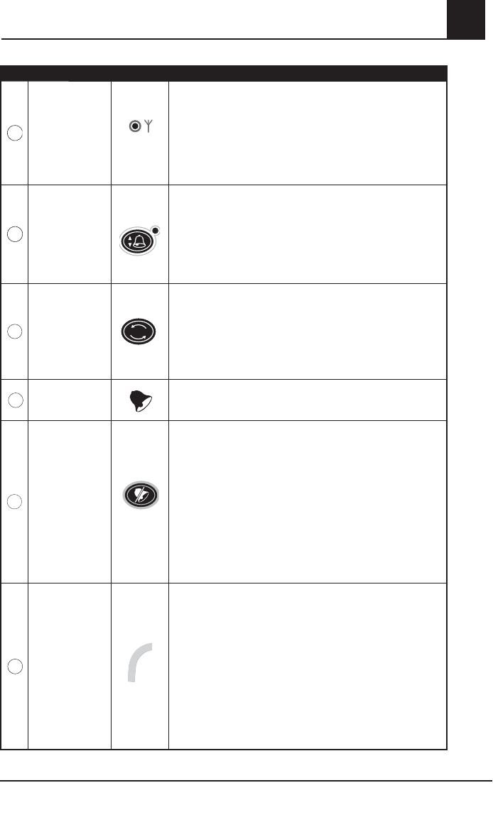
CONTROL / INDICATOR DESCRIPTION
6
Wireless
Indicator
Off: No connection to Masimo Patient SafetyNet or other
compatible interface system.
Flashing Green: Rad-87 attempts to connect to Patient
SafetyNet or other compatible interface system.
Solid Green: Rad-87 is connected to the Patient SafetyNet or
other compatible interface system.
7
Alarm Limits
Button
Used to enter the alarm menu to adjust Hi/Low SpO2, SpCO, SpMet,
SpHb, PI, PVI and pulse rate alarm limits.
The LED indicator (located above the Alarm Limits Button) will
illuminate when one or more of the factory default alarm settings
is changed to alert the user to verify alarm settings.
8
Display Button
DISPLAY
DISPLAY
Allows movement through the 3 different display screens to view
sets of parameters and measurements.
Also used to exit setup menu screens and return the display to
screen 1.
Press and hold the button down for 5 seconds to scroll through
device settings on the LCD Display.
9
Alarm Bell The Alarm Bell flashes red to indicate a high priority alarm.
10
Alarm Silence
Button
Press the Alarm Silence Button to temporarily silence patient
and low battery alarms. Press the Alarm Silence Button
when the “SEN OFF” message is flashing (i.e. the sensor
is removed from the patient) to acknowledge the end of
monitoring. In this state, all further alarms are silenced until
the Pulse CO-Oximeter starts measuring patient parameters/
measurements again.
NOTE: The alarm silence time can be set for 120, 90, 60 and
30 seconds. See Section 4 - Setup Menu Level 2.
11
System Status
Light
Solid Green: Collecting data, no alarms.
Solid Yellow:
1. low priority alarms.
2. Not monitoring and no alarms.
3. Sleep Mode.
4. Interface Alarms "Off".
Flashing Yellow:
1. Low parameter/measurement confidence.
2. Medium priority alarms.
Flashing Red: High priority alarms.
2-4 Rad-87 Pulse CO-Oximeter Operator’s Manual
2system description
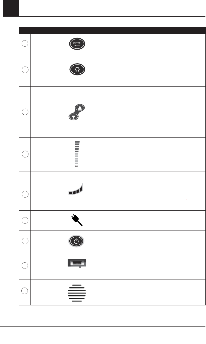
CONTROL / INDICATOR DESCRIPTION
12
Enter Button Used to enter the setup menus and to select/activate certain
entries within the menu/setup system.
13
Brightness
Button
Controls the level of the brightness for the LED display by
providing 4 levels of brightness. Each press of the button
increases the brightness one level. Once level 4 is accessed,
an additional press of the button returns the brightness to level 1.
14
Up Button
Down Button
Use these buttons to adjust the volume of the pulse beep tone.
Within the menu/setup system, these buttons are used to select
values within each menu option or the numeric value for the
parameter/measurement alarm feature.
Pressing and holding down these buttons allow for the rapid
scrolling of alarm limits.
15
Pleth Variability
Index
PVI is displayed as a percentage.
The lower the height of the bar, the less variability there is in the
PI over a respiratory cycle.
Press the Display key to toggle to the PVI numeric
measurement.
16
Battery Charge
Level Indicator
Provides a visual representation of the battery charge status.
When unplugged, bars illuminate to indicate battery charge. As
the battery discharges power, bar illumination decreases from
right to left.
A low battery status is indicated by a low audible beep and the
first battery bar to the left flashing green.
17
AC Power
Indicator
The AC Power Indicator is illuminated when the Rad-87 is
connected to AC power and during battery charging.
18
Power Button
Used to turn the device on and off. Press the button once to
power on the device. Press the button for 2 seconds to power
off the device.
19
Pulse
CO-Oximeter
Patient Cable
Connector
Connects to a Masimo Pulse CO-Oximeter sensor or Masimo
Pulse CO-Oximeter Patient Cable with a sensor.
20
Speaker Provides audible indication of alarm conditions, pulse tone and
feedback for key-presses.
Rad-87 Pulse CO-Oximeter Operator’s Manual 2-5
2
system description
RAD-87 PULSE CO-OXIMETER - VERTICAL
888
888
888
888
888
888
888
888
88
8
88
8
8
19
17
13
10
5
9
12
6
20
1
14
7
2
4
15
11
18
16
MAX
MAX
NORM
NORM
3
10.1
97
76
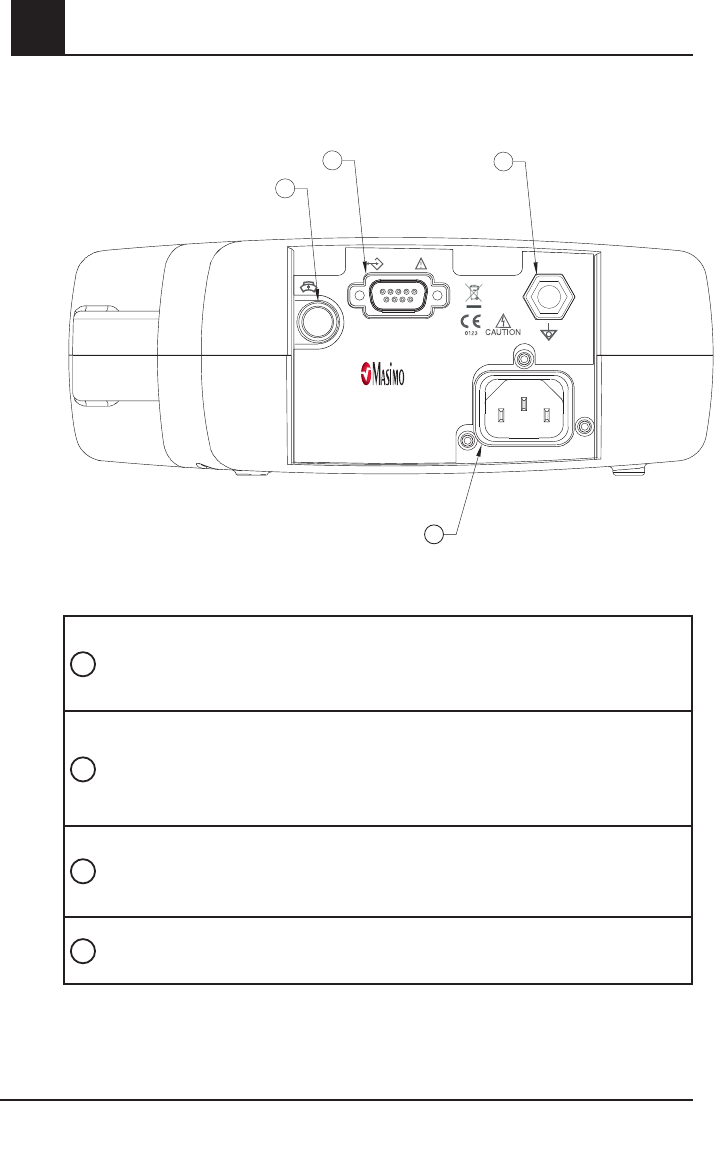
2-6 Rad-87 Pulse CO-Oximeter Operator’s Manual
2system description
1NURSE CALL
CONNECTOR
Use the 1/4” round Connector to interface with a nurse call system.
This is a stereo output and should be utilized with a stereo cable. All
external device connections to the Nurse Call Connector must be
IEC-60950 compliant.
2SERIAL OUTPUT
CONNECTOR
Use the Serial Output Connector to connect a serial device, including
a serial printer, RadNet Interface Module, or PC, to the Rad-87.
See Section 7, Output Interface Specifications. All external device
connections to the Serial Output Connector must be IEC-60950
compliant.
3POWER ENTRY
MODULE
The power entry module contains the input connector for AC power.
The AC input provides power to the system from the AC line. Always
connect the Rad-87 to the main power for continuous operation and/
or battery recharging.
4EQUIPOTENTIAL
GROUND CONNECTOR Use the Equipotential Ground Connector for grounding.
1
2
3
4
32294/4778A-1207
100-240v~50-60 Hz 15VA MAX100-240v~50-60 Hz 15VA MAX
P2
RS-232
P1
Made in USA
Manufactured by:
Masimo Corporation
Irvine, CA 92618
USA
Rx Only
Distributed by:
Masimo Corporation
Irvine, CA 92618
USA
Covered by one or more of the following U.S. Patents: RE38,492, RE38,476,
7,221,971, 7,215,986, 7,215,984, 7,186,966, 6,979,812, 6,861,639, 6,850,787,
6,826,419, 6,816,741, 6,745,060, 6,699,194, 6,684,090, 6,654,624, 6,650,917,
6,643,530, 6,606,511, 6,515,273, 6,501,975, 6,463,311, 6,430,525, 6,388,240,
6,360,114, 6,263,222, 6,236,872, 6,229,856, 6,157,850, 6,067,462, 6,011,986,
6,002,952, 5,919,134, 5,769,785, 5,758,644, 5,685,299, 5,632,272, 5,490,505,
5,482,036, international equivalents, or one or more of the patents referenced at
www.masimo.com/patents. Other patents pending.
RAD-87 REAR PANEL
Rad-87 Pulse CO-Oximeter Operator’s Manual 2-7
2
system description
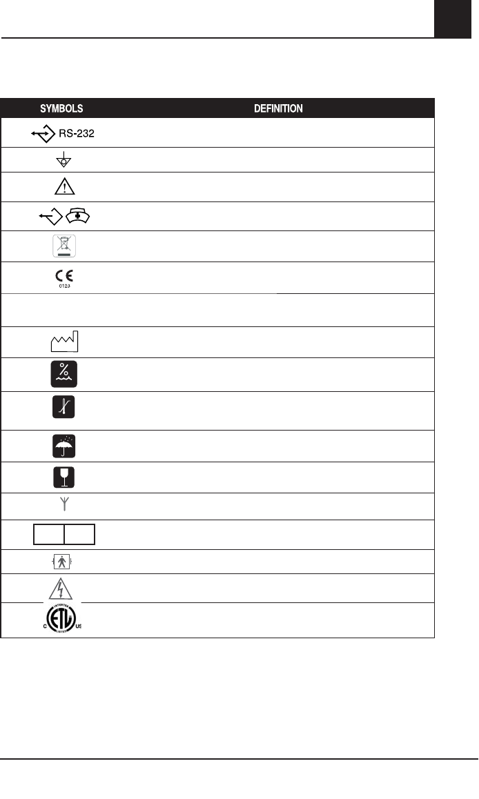
SYMBOLS
The following symbols are found on the Rad-87 or packaging and are defined below:
RS-232
Equipotential Ground Terminal
Consult accompanying documents
Nurse Call Interface
WEEE compliant
Mark of Conformity to European Medical Device Directive 93/42/EEC
Rx Only
Federal law restricts this device to sale by or on the order of a
physician (USA audiences only)
Year of manufacture
5%-95% RH
Storage humidity range: 5% to 95%
-40 C
+70 C
+1060 hPa - +500 hPa
7
95 mmHg - 375 mmHg
Storage temperature range: +70˚C to -40˚C
Storage altitude range: +1600hPa to +500hPa
Keep dry
Fragile/breakable, handle with care
Indicates wireless Radio signal (wireless radio model only)
EC REP EU authorized representative
Defi brillation Proof Type BF
Caution
Electrical Testing Laboratory certification

2-8 Rad-87 Pulse CO-Oximeter Operator’s Manual
2system description
LCD DISPLAY
The LCD Display shows radio communication information when radio communication is active
(wireless radio model only). It also shows system information. All Rad-87 models are equipped with
a LCD display which is located on the top panel of a horizontal model, or on the left side panel
of a vertical model.
The LCD Display illuminates upon start up and displays the installed parameter/measurement's
low and high alarm limits. Once the Rad-87 completes system initiation, the display light turns off.
As the front panel buttons are pressed, each menu selection is shown on the LCD Display.
When Rad-87 actively communicates with another system using the radio feature, the LCD
Display shows the following:
■ Patient SafetyNet: The LCD Display shows the information sent from the Patient SafetyNet to the
Rad-87.
■ Philips VueLink: The LCD Display shows "VueLink Conn" and "SpO2 & PR Al On" or "SpO2 & PR Al
Off".
NOTE: When the Rad-87 is interfaced to the Philips VueLink and the LCD Display shows
"SpO2 & PR AL On", SpO2 and BPM audible alarms are active at the device and
patient monitor. When the LCD Display shows "SpO2 & PR AL Off", SpO2 and BPM
audible alarms are inactive at the device but active at the patient monitor.
Additionally, if the Display Button is pressed down for 5 seconds, the LCD Display shows the
following settings three times and then returns to the default screen. The display cycle can be
interrupted by pressing any button except for the Sensitivity or the Alarm Silence Buttons.
■ Label: System Settings
■ Monitoring Mode: Normal, Sleep or Home
■ Installed parameter/measurement's low and high alarm limits
■ Audible Alarm
■ Alarm Volume
■ Alarm Silence
■ Alarm Delay
■ Rapid Desat
■ Sensitivity
■ Averaging Time

Rad-87 Pulse CO-Oximeter Operator’s Manual 3-1
3
Introduction
Before the Rad-87 Pulse CO-Oximeter can be used in a clinical setting, it needs to be inspected,
properly setup and the batteries need to be fully charged.
Unpacking and inspection
Remove the instrument from the shipping carton and examine it for signs of shipping damage.
Check all materials against the packing list. Save all packing materials, invoice and bill of lading.
These may be required to process a claim with the carrier.
If anything is missing or damaged, contact the Technical Service Department. The contact address
and phone numbers are listed in Section 9, Service and Repair.
Preparation for monitoring
The following sections of the manual describe the preparation, set-up and initial installation of
the Rad-87 Pulse CO-Oximeter.
RAD-87 POWER REQUIREMENTS
Always use a hospital grade, AC power cable to connect the Rad-87 to an AC power source.
CAUTION: DO NOT CONNECT THE RAD-87 TO AN AC OUTLET CONTROLLED BY A
SWITCH.
Verify the AC power voltage and frequency before use. Verify that the power source can provide
adequate power rating as indicated on the rear panel of the Rad-87.
The Rad-87 is designed to operate on 100 to 240VAC, 47-83 Hz. The device is rated at 15 VA
max.
Connect a hospital grade power cable to the power entry module of the Rad-87 device(IEC-320
connector type at the device). Connect the power cable to an AC power source. Ensure that
the device is adequately powered by verifying that the AC power indicator on the Rad-87 is
illuminated.
CAUTION:
■ CONNECT THE RAD-87 ONLY TO A HOSPITAL-GRADE RECEPTACLE (FOR HOSPITAL USE).
■ DO NOT UNDER ANY CIRCUMSTANCES REMOVE THE GROUNDING CONDUCTOR FROM THE
POWER PLUG.
■ DO NOT USE EXTENSION CORDS OR ADAPTERS OF ANY TYPE. THE POWER CORD AND PLUG
MUST BE INTACT AND UNDAMAGED.
■ USE THE POWER CORD AS THE MEANS TO DISCONNECT THE DEVICE FROM THE MAINS
POWER SUPPLY.
■ IF THERE IS ANY DOUBT ABOUT THE INTEGRITY OF THE PROTECTIVE EARTH
CONDUCTOR ARRANGEMENT, OPERATE THE RAD-87 ON INTERNAL BATTERY POWER
UNTIL THE AC POWER SUPPLY PROTECTIVE CONDUCTOR IS FULLY FUNCTIONAL.
■ TO ENSURE PATIENT ELECTRICAL ISOLATION, CONNECT ONLY TO OTHER
EQUIPMENT WITH ELECTRICALLY ISOLATED CIRCUITS.
■ DO NOT CONNECT TO AN ELECTRICAL OUTLET CONTROLLED BY A WALL SWITCH OR
DIMMER.
setup

3-2 Rad-87 Pulse CO-Oximeter Operator’s Manual
3
INITIAL BATTERY CHARGING
Before use, the Rad-87 battery needs to be fully charged.
To charge the internal battery, connect the AC power cord to an AC outlet and to the Power Entry Module
located on the back of the Rad-87. The AC Power Indicator illuminates. The AC Power Indicator will
remain illuminated while the battery is charging. The Battery Charge Level Indicator will not be illuminated
unless the device is operating on battery power. Once the battery is fully charged, the device has up to 4
hours of battery life. See Section 7-2, Specifications.
INITIAL INSTALLATION
Place the Rad-87 on a stable hard flat surface near the patient. Always place the Rad-87 on a
dry surface. Maintain a minimum of 1 inch (2.54 cm) free space around the device. Make sure
that Rad-87 loudspeaker is not covered to avoid a muffled alarm sound.
The Rad-87 should not be operated outside the following environmental conditions:
OPERATING ENVIRONMENTAL CONDITIONS
TEMPERATURE +5°C to +40°C, +41°F to +104°F
HUMIDITY 5% to 95%, non-condensing
OPERATING ALTITUDE 500 mbar to 1060 mbar pressure
-1000 ft to 18,000 ft (-304 m to 5,486 m)
Configure the Rad-87 for your regional power line frequency (50 or 60 hz) if needed. Default
Configure the Rad-87 for your regional power line frequency (50 or 60 hz) if needed. Default
is 60 hz (standard for the United States). See Section 4,
is 60 hz (standard for the United States). See Section 4,
Operation, Setup menu Level 3, Line
Operation, Setup menu Level 3, Line
Frequency.
Frequency.
CAUTION:
CAUTION:
T
T
HE DEVICE MUST BE CONFIGURED TO MATCH YOUR LOCAL POWER LINE
HE DEVICE MUST BE CONFIGURED TO MATCH YOUR LOCAL POWER LINE
FREQUENCY TO ALLOW FOR THE CANCELLATION OF NOISE INTRODUCED
FREQUENCY TO ALLOW FOR THE CANCELLATION OF NOISE INTRODUCED
BY FLUORESCENT LIGHTS AND OTHER SOURCES.
BY FLUORESCENT LIGHTS AND OTHER SOURCES.
CAUTION:
CAUTION:
THE BATTERY SHOULD BE ADEQUATELY CHARGED TO ENSURE BACKUP
THE BATTERY SHOULD BE ADEQUATELY CHARGED TO ENSURE BACKUP
POWER IN CASE OF AC POWER DISRUPTION.
POWER IN CASE OF AC POWER DISRUPTION.
setup

Rad-87 Pulse CO-Oximeter Operator’s Manual 4-1
4
operation
Introduction
To operate the Rad-87 system effectively, the device must be set up correctly and the operator
must:
■ Know how the Rad-87 derives its readings (see Section 1).
■ Be familiar with its controls, components and operation.
■ Understand its status and alarm messages (see Section 5, Alarm and Messages and
Section 6, Troubleshooting).
Basic operation
GENERAL SETUP AND USE
1. Inspect the Rad-87 case for damage.
2. Connect a patient cable or a direct connect sensor to the Rad-87 device. Make sure it is a firm
connection and the cable is not twisted, sliced or frayed.
3. If utilizing a patient cable, select a sensor that is compatible with the Rad-87 and the patient
before connecting it to the patient cable. See section 8, Sensors and Patient Cables. If using a
single patient adhesive or disposable sensor, check that the emitter (red light) and the detector
are properly aligned. Remove any substances that may interfere with the transmission of light
between the sensor’s light source and detector.
4. Refer to the Directions for Use of the sensor before attaching the sensor to the patient.
5. Attach the sensor to the Patient. With a Masimo sensor, connect the sensor to the patient cable
with the logos lining up; make sure it is a firm connection.
6. Press the Power button to turn the Rad-87 on.
7. Verify all front-panel indicators momentarily illuminate and a tone is heard.
8. Verify the front-panel display is free of alarm and system failure messages (see Section 5,
Alarms and Messages).
NOTE: The number "0" scrolls across the screen as the system calibrates and obtains patient
data (approximately 20 seconds).
9. Verify the LED and the LCD displays shows the following (see Setup Menu Level 1;
Parameter/Measurement Alarm Limits - Screen 1, Parameter/Measurement Alarm Limits -
Screen 2, Parameter/Measurement Alarm Limits - Screen 3, and Setup Menu Level 3; Set
Mode located in this chapter):
■ Mode setting: Standard (Std) or Sleep (SLP) or Home (Hnn)
■ SpO2 Low Alarm Limit and SpO2 High Alarm Limit,
■ Pulse Rate Low Alarm Limit and Pulse Rate High Alarm Limit,
■ SpCO Low Alarm Limit and SpCO High Alarm Limit,
■ SpMet Low Alarm Limit and SpMet High Alarm Limit,
■ SpHb Low Alarm Limit and SpHb High Alarm Limit,
■ PI Low Alarm Limit and PI High Alarm Limit,
■ PVI Low Alarm Limit and PVI High Alarm Limit.
Measurement Alarm Limits - Screen 2, Parameter/Measurement Alarm Limits - Screen 3 in this
chapter).
NOTE: The number "0" scrolls across the screen as the system calibrates and obtains patient
data (approximately 20 seconds).

4-2 Rad-87 Pulse CO-Oximeter Operator’s Manual
4
Basic operation continued
10. On the LED and the LCD displays, verify the alarm limit settings (see Setup Menu Level 1,
Parameter/Measurement Alarm Limits - Screen 1, Parameter/Measurement Alarm Limits -
Screen 3 in this chapter).
NOTE: The number "0" scrolls across the screen as the system calibrates and obtains patient
data (approximately 20 seconds).
11. Verify that the patient alarms are functional by setting the high and low alarm limits beyond
the patient readings. (see Setup Menu Level 1, Parameter/Measurement Alarm Limits -
Screen 1, Parameter/Measurement Alarm Limits - Screen 2, Parameter/Measurement Alarm
Limits - Screen 3 in this chapter).
■ An alarm tone sounds.
■ The Alarm Bell flashes red for high priority alarms.
■ The System Status Light flashes red for high priority alarms, flashes yellow for medium
priority alarms and is solid yellow for low priority alarms.
■ The number value and parameter/measurement label for the violated alarm limit will
flash on the LED display.
12. Verify the sensor alarms are functional.
■ Remove the sensor from the sensor site.
■ The alarm tone sounds.
■ The Alarm Bell flashes red.
■ The System Status Light flashes red.
■ The display shows "SEN OFF" message.
Disconnect the sensor from the patient cable or Rad-87.
■ The alarm tone sounds.
■ The Alarm Bell flashes red.
■ The System Status Light flashes red.
■ The display shows "NO SEN" message.
NOTE: "NO SEN" or "SEN OFF" conditions will only generate a high priority alarm if the Rad-87 is
actively monitoring a patient when the sensor is disconnected.
13. Verify that the audible alarm can be silenced when a parameter/measurement alarm is
exceeded.
■ Create an alarm condition by lowering the high alarm limit for the pulse rate so that it
is lower than the patient value.
■ Press the Alarm Silence button.
■ The alarm tone ceases for 120 seconds (default).
■ The Alarm Bell flashes red for a high pulse rate (high priority alarm).
■ The System Status Light flashes red.
14. To begin patient monitoring:
■ Adjust the alarm limits.
■ Adjust the alarm volume.
■ Adjust the pulse beep volume.
operation

Rad-87 Pulse CO-Oximeter Operator’s Manual 4-3
4
operation
Basic operation continued
15. Verify the sensor is applied correctly and that the measured data is appropriate, see Section
4, Successful Monitoring.
16. Monitor the patient.
17. After monitoring is complete, remove the sensor from the patient and store or dispose of the
sensor according to local laws. See the Directions for Use of the sensor.
18. Press and hold the Power Button for 2 seconds to turn the Rad-87 off [3 seconds in the
Home Mode].
DEFAULT SETTINGS
The Rad-87 Pulse CO-Oximeter stores two types of default values that the device automatically
retains after a power cycle.
1. Factory defaults set by Masimo.
2. Default settings that can be changed by the user which will be remembered after a power cycle.
FACTORY DEFAULT AND USER CONFIGURABLE SETTINGS
OPTION FACTORY DEFAULTS USER CONFIGURABLE DEFAULTS
SpO2 high alarm limit "---" Off 2 to 99%
SpO2 low alarm limit 90% 1 to 98%
Pulse rate high alarm limit 140 BPM 35 to 235 BPM
Pulse rate low alarm limit 50 BPM 30 to 230 BPM
SpCO high alarm limit 10 2 to 98, then "---"
SpCO low alarm limit "---" Off "---", then 1 to 97
SpMet high alarm limit 3 1 to 99.5, then "---"
SpMet low alarm limit Off "---", then .1 to 99
SpHb high alarm limit 16 2 to 24.5, then "---"
SpHb low alarm limit 7 "---", then 1 to 24
PI high alarm limit "---" Off 0.04 to 19, then "---"
PI low alarm limit "---" Off "---", then 0.03 to 18
PVI high alarm limit "---" Off 2 to 99, then "---"
PVI low alarm limit "---" Off "---", then 1 to 98
Sensitivity APOD
Max/Normal/APOD
NOTE: MAX sensitivity will default to APOD after
a power cycle.
Display brightness Level 2 Levels 1 thru 4
Pulse tone volume Level 2 Off, Levels 1 thru 3
Alarm Silence Time 120 seconds 30, 60, 90, or 120 seconds
Alarm Volume Level 3, 70 db min Levels 1 thru 4, 87 db max
Monitoring Mode Standard (Normal) Standard, Sleep, Home
Audible Alarm Off Alarms active (On) "On/Off or muted with reminder"
Alarm Delay 5 sec 0, 5, 10, or 15 seconds
Rapid Desat Alarm 5% 5, 10, Off
Serial out ASCII 2 Philips/ASCII 1/ASCII 2
Interface Alarm Alarm On Alarm, Off/On

4-4 Rad-87 Pulse CO-Oximeter Operator’s Manual
4
FACTORY DEFAULT AND USER CONFIGURABLE SETTINGS (CONTINUED)
Nurse Call Type Alarm
Alarm and Low Signal IQ/
Low Signal IQ/
Alarm
Nurse Call Polarity Normal Normal/Invert
Line Frequency 60 Hz 60 Hz, 50 Hz
Averaging time 8 sec 2, 4, 8, 10, 12, 14, 16
SmartTone Off On/Off
FastSat Off Setting is retained after power cycle.
Device Profile settings N/A Light blue, purple, pink, orange or green
LCD Language English English (Default) French, German, Italian,
Spanish, Swedish, Dutch, Danish, Portuguese
PVI Bar On On/Off
Successful Monitoring
The following general points will aid in ensuring monitoring success.
NOTE: See Safety Information, Warnings, Cautions and Notes for additional information.
■ Place the sensor on a site that has sufficient perfusion and provides proper alignment of the
LED’s and detector.
■ Place the sensor on a site that has unrestricted blood flow.
■ Do not secure a sensor with tape.
■ Do not select a site near potential electrical interference (electro-surgical device, for example).
■ Read the sensor Directions for Use for proper sensor application.
MASIMO PULSE CO-OXIMETRY SENSORS
Before use, carefully read the Masimo sensor Directions for Use.
Use only Masimo sensors for pulse oximetry or pulse CO-Oximetry measurements.
Tissue damage can be caused by incorrect application or use of a sensor, for example by wrapping
the sensor too tightly. Inspect the sensor site as directed in the sensor Directions for Use to ensure
skin integrity and correct positioning and adhesion of the sensor.
CAUTIONS
■ DO NOT USE DAMAGED SENSORS. DO NOT USE A SENSOR WITH EXPOSED
OPTICAL OR ELECTRICAL COMPONENTS. DO NOT IMMERSE THE SENSOR IN WATER,
SOLVENTS, OR CLEANING SOLUTIONS (THE SENSORS AND CONNECTORS ARE
NOT WATERPROOF). DO NOT STERILIZE BY IRRADIATION, STEAM, AUTOCLAVE OR
ETHYLENE OXIDE UNLESS OTHERWISE INDICATED IN THE SENSOR DIRECTIONS
FOR USE. SEE THE CLEANING INSTRUCTIONS IN THE DIRECTIONS FOR USE FOR
ALL MASIMO REUSABLE SENSORS.
■ DO NOT USE DAMAGED PATIENT CABLES. DO NOT IMMERSE THE PATIENT CABLES IN
WATER, SOLVENTS, OR CLEANING SOLUTIONS (THE PATIENT CABLE CONNECTORS
ARE NOT WATERPROOF). DO NOT STERILIZE BY IRRADIATION, STEAM, AUTOCLAVE
OR ETHYLENE OXIDE.
■ DO NOT ATTEMPT TO REPROCESS, RECONDITION OR RECYCLE MASIMO SENSORS
OR PATIENT CABLES AS THESE PROCESSES MAY DAMAGE THE ELECTRICAL
COMPONENTS, POTENTIALLY LEADING TO PATIENT HARM.
operation

Rad-87 Pulse CO-Oximeter Operator’s Manual 4-5
4
operation
NUMERIC DISPLAY - SpO2
Stability of the SpO2 readings may be a good indicator of signal validity. Although stability is a relative
term, experience will provide confidence in changes that are artifactual or physiological and the speed,
timing, and behavior of each. The stability of the readings over time is affected by the averaging mode
being used. The longer the averaging time, the more stable the readings tend to become. This is due
to a dampened response as the signal is averaged over a longer period of time than during shorter
averaging times. However, longer averaging times delay the response of the device and reduce the
measured variations of SpO2 Inaccurate measurements may be caused by:
■ Elevated levels of Carboxyhemoglobin.
■ Elevated levels of Methemoglobin.
■ Severe anemia.
■ Elevated Total Bilirubin levels.
■ Low arterial perfusion.
■ Motion artifact.
NUMERIC DISPLAY - PULSE RATE
The Pulse Rate displayed on the Rad-87 Pulse CO-Oximeter may differ slightly from the heart rate
displayed on ECG monitors due to differences in averaging times. There may also be a discrepancy
between cardiac electrical activity and peripheral arterial pulsation. Significant differences may
indicate a problem with the signal quality due to physiological changes in the patient or one of the
instruments or application of the sensor or patient cable. The pulsations from intra-aortic balloon
support can cause the pulse rate displayed on the Rad-87 to be significantly different than the ECG
heart rate.
NUMERIC DISPLAY - SpCO
A stable SpCO reading is associated with correct sensor placement, small physiological changes
during the measurement and acceptable levels of arterial perfusion in the patient’s measurement site.
Physiological changes at the measurement site are mainly caused by fluctuations in the arterial oxygen
saturation, blood concentration and perfusion. Inaccurate measurements may be caused by:
■ Elevated levels of methemoglobin.
■ Intravascular dyes such as indocyanine green or methylene blue.
■ Abnormal hemoglobin levels.
■ Low arterial perfusion.
■ Low arterial oxygen saturation levels.
■ Elevated Total Bilirubin levels.
■ Motion artifact.
NUMERIC DISPLAY - SpMet
A stable SpMet reading is associated with correct sensor placement, small physiological changes
during the measurement and acceptable levels of arterial perfusion in the patient’s measurement
site. Physiological changes at the measurement site are mainly caused by fluctuations in the arterial
oxygen saturation, blood concentration and perfusion. Inaccurate measurements may be caused
by:
■ Intravascular dyes such as indocyanine green or methylene blue.
■ Low arterial perfusion.
■ Low arterial oxygen saturation levels.
■ Elevated Total Bilirubin levels.
■ Motion artifact.

4-6 Rad-87 Pulse CO-Oximeter Operator’s Manual
4
NUMERIC DISPLAY - SpHb
A stable SpHb reading is associated with correct sensor placement, small physiological changes
during the measurement and acceptable levels of arterial perfusion at the measurement site.
Physiological changes at the measurement site are mainly caused by fluctuations in the arterial
oxygen saturation, blood concentration and perfusion. Inaccurate measurements may be caused
by:
■ Intravascular dyes such as indocyanine green or methylene blue.
■ Low arterial perfusion.
■ Low arterial oxygen saturation levels.
■ Elevated Total Bilirubin levels.
■ Motion artifact.
NUMERIC DISPLAY - SpOC
A stable SpOC reading is associated with stable readings for both SpO2 and SpHb which
comes with correct sensor placement, small physiological changes during the measurement
and acceptable levels of arterial perfusion at the measurement site. Physiological changes at the
measurement site are mainly caused by fluctuations in the oxygen saturation, blood concentration
and perfusion.
Inaccurate measurements may be caused by:
■ Intravascular dyes such as indocyanine green or methylene blue.
■ Low arterial perfusion.
■ Low arterial oxygen saturation levels.
■ Elevated Total Bilirubin levels.
■ Motion artifact.
■ Elevated levels of carboxyhemoglobin.
■ Elevated levels of methemoglobin.
■ Severe anemia may cause erroneous SpOC readings.
NUMERIC DISPLAY - (PI)
The perfusion index (PI) display and bar graph indicator provide a relative numeric indication of
the pulse strength at the monitoring site. It is a calculated percentage between the pulsatile signal
and non-pulsatile signal of arterial blood moving through the site. PI may be used to find the best
perfused site and to monitor physiological changes in the patient. It displays an operating range of
0.02 percent to 20.00 percent. A percentage greater than 1.00 percent is desired. Extreme changes
in the display number are due to motion artifact and changes in physiology and blood flow.
PLETH VARIABILITY INDEX - (PVI)
The pleth variability index (PVI) is a measure of the dynamic changes in the perfusion index (PI)
that occur during the respiratory cycle. The calculation is accomplished by measuring changes
in PI over a time interval where one or more complete respiratory cycles have occurred. PVI is
displayed as a percentage (0-100%).
The PVI bar graph is a representation of the calculated value. The lower the height of the bar,
the less variability there is in the PI over a respiratory cycle. Press the Display key to toggle to
the PVI numeric measurement.
operation

Rad-87 Pulse CO-Oximeter Operator’s Manual 4-7
4
operation
LOW PERFUSION
The Rad-87 indicates perfusion on a 10-bar LED indicator. The lower two segments of the bar will
turn red when the amplitude of the arterial pulsations is very low (low perfusion).
It has been suggested that at extremely low perfusion levels, pulse oximeters can measure
peripheral saturation, which may differ from central arterial saturation3. This “localized hypoxemia”
may result from the metabolic demands of other tissues extracting oxygen proximal to the
monitoring site under conditions of sustained peripheral hypoperfusion. (This may occur even with
a pulse rate that correlates with the ECG heart rate.)
CAUTION: IF THE LOW PERFUSION MESSAGE IS FREQUENTLY DISPLAYED, FIND A
BETTER-PERFUSED MONITORING SITE. IN THE INTERIM, ASSESS THE
PATIENT AND, IF INDICATED, VERIFY OXYGENATION STATUS THROUGH OTHER
MEANS.
3 Severinghaus JW, Spellman MJ. Pulse Oximeter Failure Thresholds in Hypotension and Vasoconstriction.
Anesthesiology 1990; 73:532-537
SIGNAL IQ - (SIQ)
The Rad-87 Pulse CO-Oximeter display provides a visual indicator of signal quality and an alert
when the displayed SpO2 values are not based on adequate signal quality. The signal quality
indicator displayed on the Rad-87 is called the Signal IQ. The Signal IQ can be used to identify the
occurrence of a patient’s pulse and the associated signal quality of the measurement.
The Signal IQ is represented as a bar indicator where the height of the bar coincides with the
strength of an arterial pulsation. Even with a plethysmographic waveform obscured by artifact, the
Rad-87 locates the arterial pulsation. The pulse tone (when enabled) coincides with the rise of the
Signal IQ Index.
The height of the Signal IQ Index indicates the quality of the measured signal. A high Signal IQ
Index indicates that the SpO2 measurement is based on a good quality signal. A small Signal IQ
Index indicates that the SpO2 measurement is based on data with low signal quality. When the
signal quality is very low the accuracy of the SpO2 measurement may be compromised. When the
Signal IQ is low and the bar turns red, proceed with caution and do the following:
■ Assess the patient.
■ Check the sensor and ensure proper sensor application. The sensor must be well secured
to the site for the Rad-87 to maintain accurate readings. Also, misalignment of the sensor’s
emitter and detector can result in smaller signals.
■ Determine if an extreme change in the patient’s physiology and blood flow at the monitoring
site occurred, (e.g. an inflated blood pressure cuff, a squeezing motion, sampling of an arterial
blood specimen from the hand containing the pulse oximetry sensor, severe hypotension,
peripheral vasoconstriction in response to hypothermia, medications, or an episode of
Raynaud’s syndrome).
■ With neonates or infants, check that the peripheral blood flow to the sensor site is not
interrupted. Interruption, for example, may occur while lifting or crossing their legs, during a
diaper change.
After performing the above, if the Low Signal IQ message is displayed frequently or continuously
obtaining an arterial blood specimen for CO-Oximetry analysis may be considered to verify the
arterial oxygen saturation value.

4-8 Rad-87 Pulse CO-Oximeter Operator’s Manual
4
SENSOR PLACEMENT
If the SpO2, SpCO, SpMet or SpHb readings are questionable or unavailable, do the following:
■ Make sure the emitter and detector are aligned directly opposite each other.
■ Select a site where the distance between the emitter and detector is minimized.
■ Wipe the sensor site with a 70% isopropyl alcohol pad or rubefacient cream (10-30% methyl
salicylate and 2-10% menthol) for 20-30 seconds to increase perfusion. However, strong
vasodilator creams, such as nitroglycerin paste, are not recommended.
■ If possible, remove electrical noise sources such as electro-surgical devices or other electrical/
electronic equipment. If these solutions are not possible, operate the Rad-87 on battery power, or
try plugging the device into a different electrical outlet.
■ If artificial nails or excessive fingernail polish are present, select another site or remove the polish/
artificial nails.
■ If possible, ensure that the sensor is placed in a location with low ambient light. Although the
Rad-87 with integrated Masimo Rainbow SET technology has significant immunity to ambient
light, excessive ambient light may cause readings to be incorrect.
CAUTION: IF ANY MEASUREMENT SEEMS QUESTIONABLE, FIRST CHECK THE
PATIENT’S VITAL SIGNS BY ALTERNATE MEANS AND THEN CHECK THE PULSE
CO-OXIMETER FOR PROPER FUNCTIONING.
SENSITIVITY
The Rad-87 Pulse CO-Oximeter is equipped with 3 different sensitivity modes. Each mode allows
the clinician to change the sensitivity settings of the device to meet the increased demands of the
patient’s physiological condition or enable it to work during periods of low perfusion and/or motion.
They are as follows:
■ Normal Sensitivity (NORM) – This is the recommended mode for patients that are
experiencing some compromise in blood flow or perfusion. It is advisable for care areas where
patients are observed frequently, such as an intensive care unit (ICU).
■ Adaptive Probe Off Detection (APOD) – This is the recommended start-up monitoring mode
for most patients with acceptable perfusion or where a more robust sensor off detection is
desired. It is the suggested mode for care areas where patients are not visually monitored
continuously. This mode delivers enhanced protection against erroneous pulse rate and
arterial oxygen saturation readings when a sensor becomes inadvertently detached from a
patient.
■ Maximum Sensitivity (MAX) - This mode is recommended for patients with low perfusion or
when the low perfusion or low signal quality message is displayed on the screen in APOD or
normal sensitivity mode. This mode is not recommended for care areas where patients are
not monitored visually, such as general wards. It is designed to interpret and display data at
the measuring site when the signal may be weak due to decreased perfusion. When a sensor
becomes detached from a patient, it will have compromised protection against erroneous
pulse rate and arterial saturation readings. Also, after a power off and on cycle, the sensitivity
will change from the MAX to the factory default or user configured default setting of APOD or
NORM.
CAUTION: WHEN USING THE MAXIMUM SENSITIVITY SETTING, THE PERFORMANCE OF
THE SENSOR OFF DETECTION MAY BE COMPROMISED. IF THE DEVICE IS IN
THIS SETTING AND THE SENSOR BECOMES DISLODGED FROM THE PATIENT,
THE POTENTIAL FOR FALSE READINGS MAY OCCUR DUE TO ENVIRONMENTAL
‘NOISE’ SUCH AS LIGHT, VIBRATION AND EXCESSIVE AIR MOVEMENT.
operation
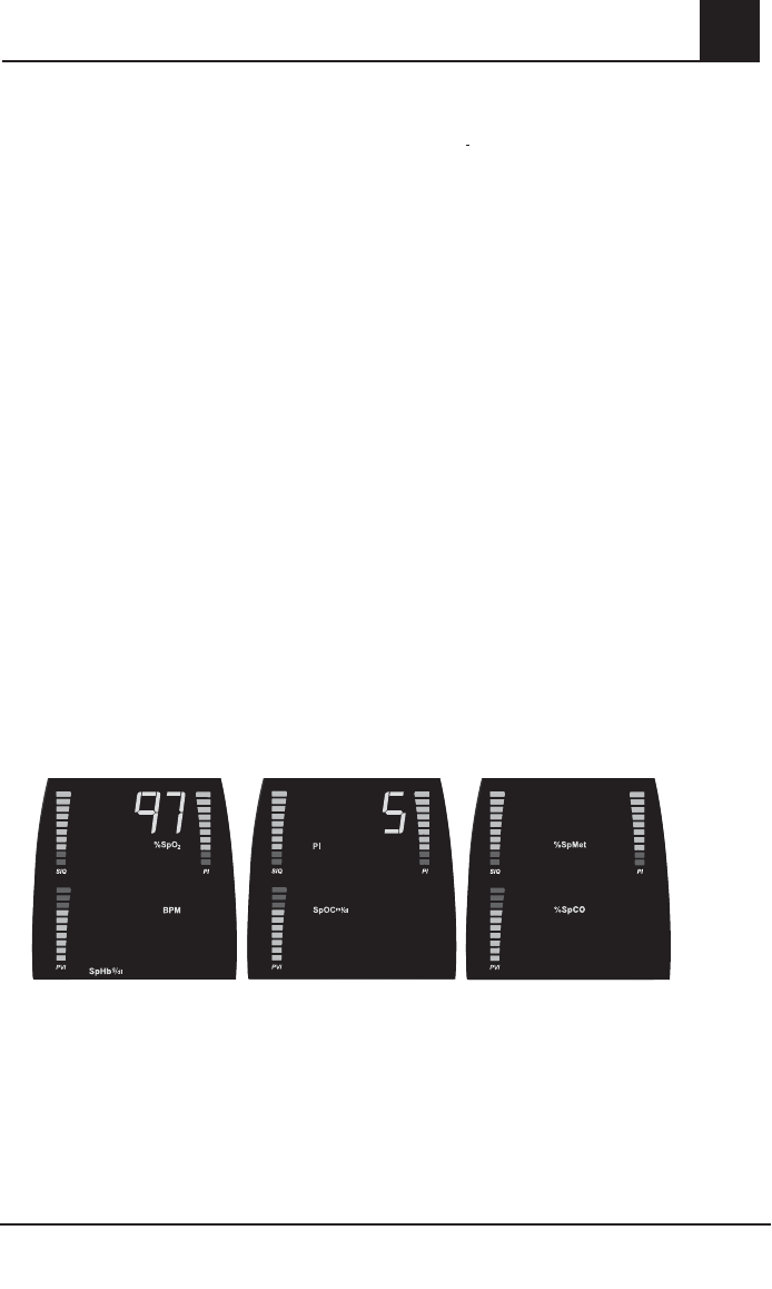
Rad-87 Pulse CO-Oximeter Operator’s Manual 4-9
4
operation
LOW BATTERY AUDIBLE ALARM
If a low battery condition occurs the audible alarm can be silenced until power cycle by pressing the
Alarm Silence Button. Refer to Setup Menu Level 2 in this section to change setting.
If a low battery condition occurs while not monitoring a patient, a low priority audible alarm will
sound and can be silenced by pressing the Alarm Silence Button. The audible alarm is silenced
until the power is cycled or patient monitoring begins.
While audible alarms are silenced, the first Battery Level Indicator bar to the left flashes green, and
the System Status Light flashes yellow to provide a visual alert for the user.
When a low battery condition occurs, immediately discontinue patient monitoring and plug the
Rad-87 into AC power. The AC Power Indicator on the Rad-87 illuminates and remains illuminated
while the battery is charging, however, the Battery Charge Level Indicator does not illuminate. Once
the battery is fully charged all Battery Charge Level Indicators illuminate green when unplugged.
During normal patient monitoring, the Battery Charge Bars (Battery Charge Level Indicator)
illuminate green from left to right to indicate the approximate amount of battery charge when
unplugged.
CAUTION:
CAUTION:
THE BATTERY SHOULD BE ADEQUATELY CHARGED TO ENSURE BACKUP
THE BATTERY SHOULD BE ADEQUATELY CHARGED TO ENSURE BACKUP
POWER IN CASE OF AC POWER DISRUPTION.
POWER IN CASE OF AC POWER DISRUPTION.
Normal patient monitoring
When all optional parameters/measurements are installed and during normal operation, the Rad-87
display shows Screen 1 containing arterial oxygen saturation (%SpO2) and pulse rate in beats per
minute (BPM) and total hemoglobin (SpHb g/dl)*. By pressing the Display Button once, the display
changes to show Screen 2 containing total arterial oxygen content (SpOC ml/dl)* perfusion index
(PI) and pleth variability index (PVI)*. Pressing the Display Button again changes the display to
show Screen 3 containing methemoglobin (%SpMet)* and carboxyhemoglobin (%SpCO)*. An
additional press of the Display Button returns the display to Screen 1, the home display screen.
*Optional parameters/measurements: SpCO, SpMet, SpHb, SPOC, PVI
Display Screens showing Parameters/Measurements -Default Locations
.
PVI
10.1 3
20
1.60
13
76
Screen 1
Home display screen
Screen 2 Screen 3
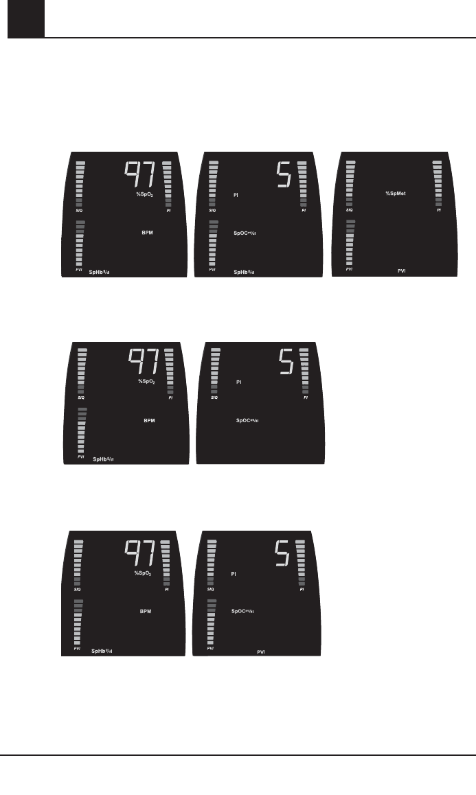
4-10 Rad-87 Pulse CO-Oximeter Operator’s Manual
4
Normal patient monitoring continued
If SpMet and SpCO are/or not installed, the display will only move from Screen 1 to Screen 3
when the Display Button is pressed; Screen 2 will not show. By pressing the Display Button again,
the display will move from Screen 3 to Screen 1.
Display Screens with All Parameters and Measurements
Display Screens when SpMet, SpCO and PVI Are Not Installed
Display Screens with SpHb and PVI Installed and SpMet and SpCO Not Installed
operation
10.1 3
20
%SpCO
1.60
10.1
13
76
Screen 1
Home display screen
No Screen 3
Screen 2
Screen 3
10.1
1376
10.1 3
1376
Screen 1
Home display screen
Screen 2
No Screen 3
Screen 1
Home display screen
Screen 2
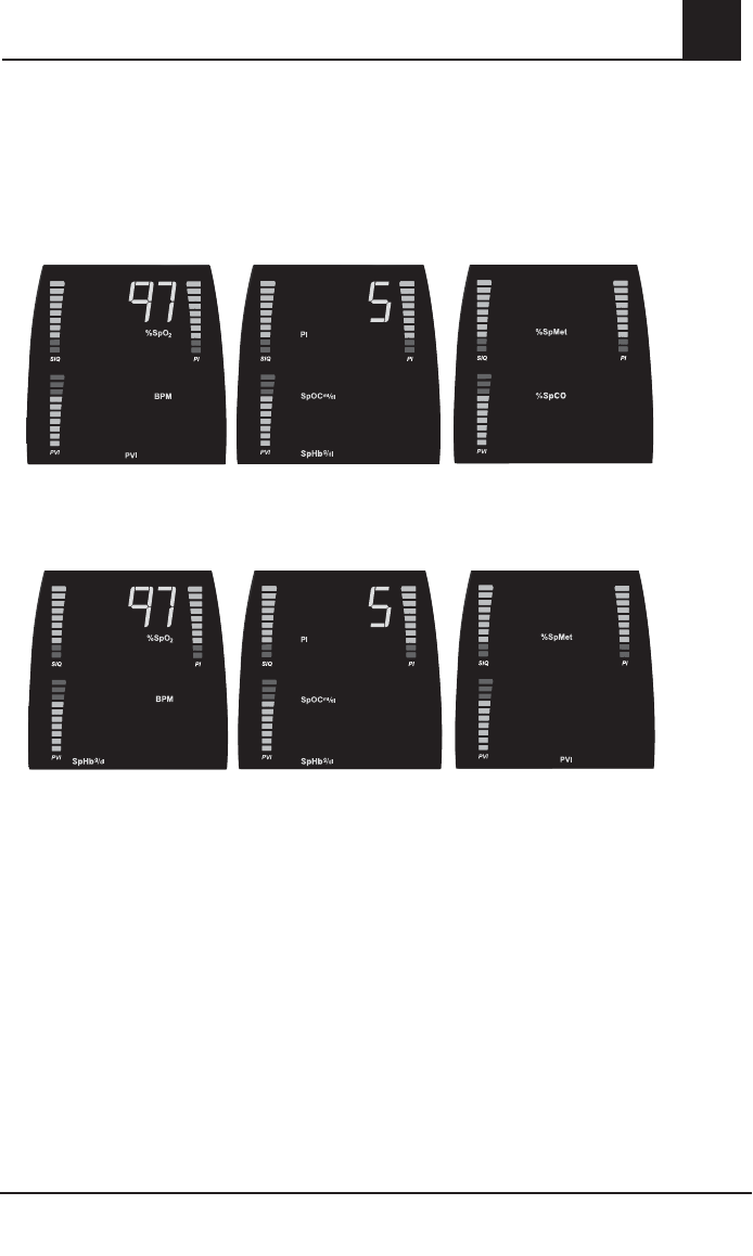
Rad-87 Pulse CO-Oximeter Operator’s Manual 4-11
4
operation
PARAMETER/MEASUREMENT SELECTION
The bottom fi eld of any display screen may be confi gured to show SpHb or PVI (see Parameter
Select menus). Once SpHb or PVI is confi gured to show on a screen different from the default
location, the alarm limit menu for SpHb or PVI can be accessed from the new screen by
pressing the Alarm Limits Button.
Display Screens Showing PVI on Screen 1
3
1.60
10.1
201376
Display Screens Showing SpHb on Screen 1 and 2
10.1 3
20
%SpCO
1.60
10.1
13
76
Screen 1
Home display screen
Screen 2 Screen 3
Screen 1
Home display screen
Screen 2 Screen 3

4-12 Rad-87 Pulse CO-Oximeter Operator’s Manual
4
SETUP MENU
This section gives an overview of the Rad-87 menu selections available. To access the menu levels
and navigate through the menu selections, use the front panel buttons, Enter Button and Up/Down
Buttons as indicated in the following sections. Sub-sections describe each menu item in more detail.
The Rad-87 has options that allow user configuration to accommodate specific needs.
MENU NAVIGATION
The Rad-87 set-up and configuration options are accessed through the menu system. Three levels
of menus are available to the user. Once a menu level is accessed, a front panel button (Level 1 only)
or the Enter Button (Level 2 and 3) is used to move from one option to the next allowing repeated
cycling through the options. The Up and Down Buttons are used to adjust values within each option.
The parameter/measurement value is set when the Enter Button is pressed. Pressing the Display
Button exits the menus and returns the device to Screen 1.
When accessing the Rad-87 menu, each selection will be communicated visually on the LED (front
of device) and LCD (top of device) displays, simultaneously.
NOTE: The Rad-87 will automatically ‘time out’ of the setup menu after 10 seconds with no button
presses.
SETUP MENU LEVEL 1
Setup Menu Level 1 contains the parameters/measurements and settings that are adjusted most
often for patient monitoring; alarm limits, display brightness, and sensitivity settings. Pressing the
Display Button while viewing alarm limit settings allows the user to exit the Setup Menu and return
to Screen 1.
operation
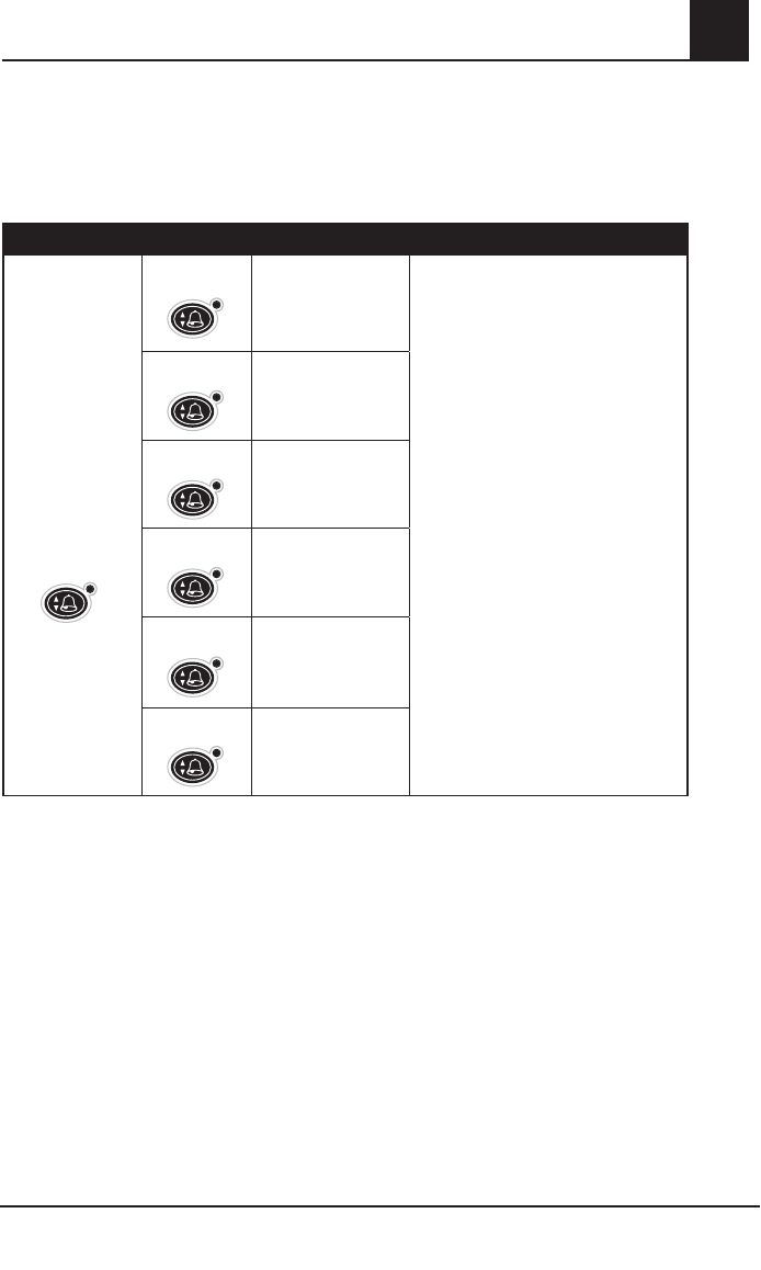
Rad-87 Pulse CO-Oximeter Operator’s Manual 4-13
4
operation
SETUP MENU LEVEL 1 (CONTINUED)
PARAMETER/MEASUREMENT ALARM LIMITS - SCREEN 1
To access alarm limits for parameters/measurements contained on Screen 1, press the Alarm Limits
Button to access the Alarm Limits menu for Screen 1 parameters/measurements.
BUTTONS SETTINGS
Use the Alarm
Limits Button to
access the alarm
limits options and
move between
options.
Press once
%SpO2 LO
Use Up or Down Buttons to adjust the
value to the desired setting
AND
press the Alarm Limits Button or Enter
Button to accept the setting and move
to the next option. Once the last option
is accessed an additional press of the
Alarm Limits Button or Enter Button will
return the device to Screen 1.
OR
press the Display Button to exit at any
time and return to Screen 1.
Press 2x
%SpO2 HI
Press 3x
Pulse rate (BPM) LO
Press 4x
Pulse rate (BPM) HI
Press 5x
SpHb g/dl LO
Press 6x
SpHb g/dl HI
NOTE: User default settings can be changed for specific patient environments.
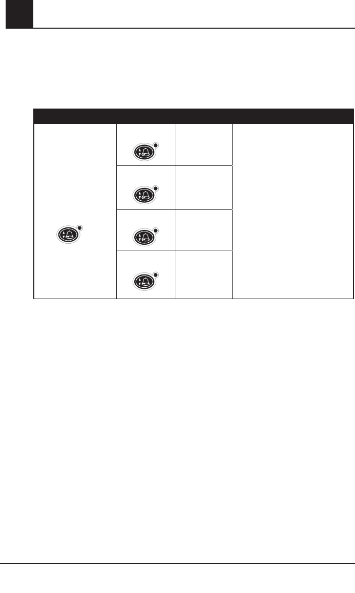
4-14 Rad-87 Pulse CO-Oximeter Operator’s Manual
4operation
SETUP MENU LEVEL 1 (CONTINUED)
PARAMETER/MEASUREMENT ALARM LIMITS - SCREEN 2
To access alarm limits for parameters/measurements contained on Screen 2, press the Display
Button to move from Screen 1 to Screen 2. From Screen 2, press the Alarm Limits Button to access
the Alarm Limits menu for Screen 2 parameters/measurements.
BUTTONS SETTINGS
Use the Alarm Limits
Button to access the
alarm limits options and
move between options.
Press once
PI LO Use Up or Down Buttons to adjust
the value to the desired setting
AND
press the Alarm Limits Button or
Enter Button to accept the setting
and move to the next option. Once
the last option is accessed an
additional press of the Alarm Limits
Button will return the device to
Screen 2.
OR
press the Display Button to exit at
any time and return to Screen 2.
Press 2x
PI HI
Press 3x
PVI LO
Press 4x
PVI HI
NOTE: User default settings can be changed for specific patient environments.
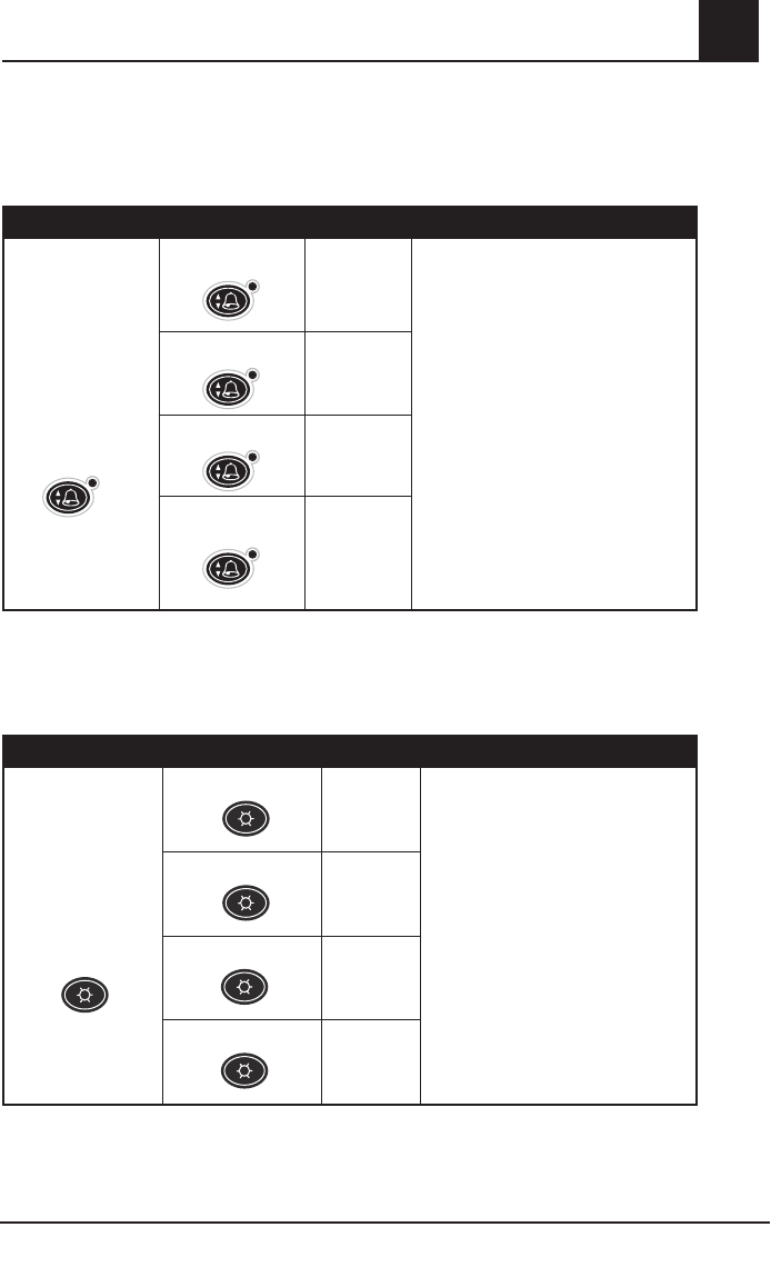
Rad-87 Pulse CO-Oximeter Operator’s Manual 4-15
4
operation
PARAMETER/MEASUREMENT ALARM LIMITS - SCREEN 3
To access alarm limits for parameters/measurements contained on Screen 3, press the Display
Button two times to move from Screen 1 to Screen 3. Press the Alarm Limits Button from Screen 3
to access the Alarm Limits menu for Screen 3 parameters/measurements.
BUTTONS SETTINGS
Use the Alarm
Limits Button to
access the alarm
limits options and
move between
options.
Press once
%SpMet LO Use Up or Down Buttons to adjust the
value to the desired setting
AND
press the Alarm Limits Button or Enter
Button to accept the setting and move
to the next option. Once the High Pulse
rate limit is accessed an additional
press of the Alarm Limits Button or
Enter Button will return the device to
Screen 3.
OR
press the Display Button to exit at any
time and return to Screen 3.
Press 2x
%SpMet HI
Press 3x
%SpCO LO
Press 4x
%SpCO HI
NOTE: User default settings can be changed for specific patient environments.
LED BRIGHTNESS
The Display screen and all active LED indicators are effected while adjusting this setting.
BUTTONS SETTINGS
Use the Brightness
Button to access
the LED brightness
options and move
between options.
Press once Default
Level 2
Use the Brightness Button to move
between menu options and the Enter
Button to accept the setting and return
to the home display screen.
Press 2x
Level 3
Press 3x
Level 4
Press 4x
Level 1
NOTE: User default settings can be changed for specific patient environments.
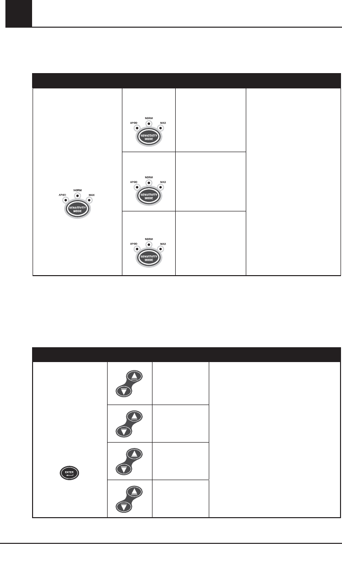
4-16 Rad-87 Pulse CO-Oximeter Operator’s Manual
4
SETUP MENU LEVEL 1 (CONTINUED)
SENSITIVITY
BUTTONS SETTING
Use the Sensitivity Button
to access the sensitivity
options and move between
options.
Press once
Default
APOD
Use the Sensitivity Button to
move between menu options
and accept the setting.
Press 2x
NORM
Press 3x MAX
(The MAX Indicator
flashes in this
mode.)
SETUP MENU LEVEL 2
Level 2 menu contains parameters and settings that are not changed as frequently as Level
1. These include alarm volume, alarm silence, alarm delay, clear trend and button volume
parameters.
ALARM VOLUME
BUTTONS SETTINGS
Use the Enter Button
to access the Alarm
Volume menu and to
move between Level
2 menus.
Default
Level 3
Use Up or Down Button to move between
settings and the Enter Button to accept
the setting and move to the next menu
screen.
OR
press the Display Button to exit without
saving the new setting and to return to
the home display screen.
Level 4
Level 1
Level 2
operation
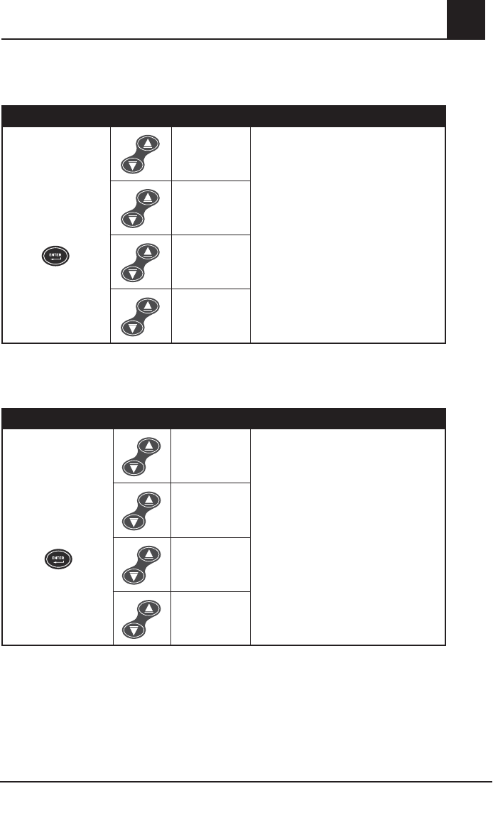
Rad-87 Pulse CO-Oximeter Operator’s Manual 4-17
4
operation
SETUP MENU LEVEL 2 (CONTINUED)
ALARM SILENCE
BUTTONS SETTINGS
Press the Enter Button
again to move to the
next menu.
2x
Default
120 seconds
Use Up or Down Button to move between
settings and the Enter Button to accept the
setting and move to the next menu screen.
OR
press the Display Button to exit without
saving the new setting and to return to the
home display screen.
90 seconds
60 seconds
30 seconds
ALARM DELAY
Alarm delay allows the user to adjust the time in which the audible status indicator will occur after
an alarm condition has been initiated.
BUTTONS SETTINGS
Press the Enter Button
again to move to the
next menu.
3x
Default
5 seconds
Use Up or Down Button to move between
settings and the Enter Button to accept the
setting and move to the next menu screen.
OR
press the Display Button to exit without
saving the new setting and to return to the
home display screen.
0 seconds
15 seconds
10 seconds
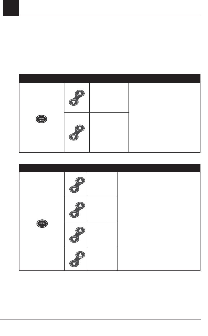
4-18 Rad-87 Pulse CO-Oximeter Operator’s Manual
4operation
SETUP MENU LEVEL 2 (CONTINUED)
CLEAR TREND
The Rad-87 only stores data in the trend memory while the device is turned on. Trend data saves
to the memory until the memory is full or cleared by the user.
NOTE: It is recommended that you clear the trend prior to performing a new patient data
collection procedure.
BUTTON SETTING
Press the Enter Button
again to move to the
next menu.
4x
Default
NO
Use Up or Down Button to move
between settings and the Enter
Button to accept the setting and move
to the next menu screen.
OR
press the Display Button to exit
without saving the new setting and to
return to the home display screen.
YES
(Clear trend)
BUTTON VOLUME
BUTTON SETTING
Press the Enter Button
again to move to the
next menu.
5x
Default
Level 2
Use Up or Down Button to move between
settings and the Enter Button to accept the
setting and move to the next menu screen.
OR
press the Display Button to exit without
saving the new setting and to return to the
home display screen.
Level 1
Off
Level 3
FASTSAT
FastSat enables rapid tracking of arterial oxygen saturation changes. Arterial oxygen saturation
data is averaged using pulse oximeter averaging algorithms to smooth the trend. When the Rad-87
is set to FastSat “On”, the averaging algorithm evaluates all the saturation values providing an
averaged saturation value that is a better representation of the patient’s current oxygenation status.
With FastSat, the averaging time is dependent on the input signal.

Rad-87 Pulse CO-Oximeter Operator’s Manual 4-19
4
operation
SETUP MENU LEVEL 2 (CONTINUED)
FASTSAT
BUTTON SETTING
Press the Enter Button
again to move to the
next menu.
6x
Default
Off
Use Up or Down Button to move
between settings and the Enter Button
to accept the setting and move to the
Alarm Volume menu.
OR
press the Display Button to exit without
saving the new setting and to return to
the home display screen.
On
Trend setup and use
INTRODUCTION
The Rad-87 can store up to 72 hours of trend data captured at 2 second intervals. The trend data
can then be transferred to a PC for evaluation.
A serial cable is required to connect the Rad-87 to a PC. Patient monitoring is not possible while
trend memory is being transferred to a PC.
Trend data is stored in non-volatile memory, so it is not erased when the device is shut off.
A trend data download is initiated using the TrendCom utility which downloads the trend data and
saves it to an ASCII text (.out) file with an output delimiter option.
NOTE: Rad-87 Serial Ouput must be set to ASCII 2 for successful download of trending data. Refer
to the Serial Output menu and settings located farther in this chapter.
TRENDCOM UTILITY INSTALLATION
Copy the TrendCom utility from the TrendCom CD onto a PC running MS-Windows.
TRENDCOM UTILITY OPERATION
1. Turn Rad-87 off if not already off.
2. Connect serial cable to Rad-87 and other end to a com port on the PC.
3. Turn the Rad-87 on.
4. Start the TrendCom utility on the PC.
5. Select Rad-87 from the first pull-down menu.
6. Select the appropriate com port number from the second pull-down menu, if necessary.
7. Select the Output Delimiter Option (Tab, Comma or Space).
8. Select the RETRIEVE TREND button on the TrendCom utility. Select the desired location
and assign a file name for the trend file. Select SAVE.

4-20 Rad-87 Pulse CO-Oximeter Operator’s Manual
4operation
Trend setup and use continued
9. The Rad-87 will display “dat out” while trend data is being transferred. A progress bar will
advance to indicate the status of the download. Larger trend files will take longer to download.
Transfer time is approximately 20 seconds per hour of trend data.
NOTE: During download of trend information, all normal Rad-87 functions are unavailable and the
keypad is locked, except for the power button.
10 When trend data transfer is complete, close TrendCom and disconnect the Rad-87 from the
serial cable.
11. Turn the Rad-87 off to exit the trend download mode.
NOTE: Contact USB to serial port adapter manufacturer for assistance or support.
ERASING TREND MEMORY
To erase (clear) the trend memory, set the Clear Trend option to Yes and press the Enter Button to
accept the setting and clear the data from the memory. Refer to the Clear Trend menu located before
this Trend setup and use section.
The Rad-87 continuously trends data. When performing a new study and gathering data on a
new patient, it is highly recommended the "clear function" be utilized in order for the results to be
separate. Turning the Rad-87 off will not erase the trend data.
TREND DATA FORMAT
After a successful download of the trend data, a .out file will be created containing the trend-dump
information in ASCII delimited format. The format is defined in the following table.

Rad-87 Pulse CO-Oximeter Operator’s Manual 4-21
4
operation
TREND DATA FORMAT (CONTINUED)
PARAMETER SPECIFICATION
Date MM\DD\YY
Time HH:MM:SS
Installed
Parameter/
Measurement
Numeric value (see the display ranges in the Factory and User Configurable Default
Settings table located at the beginning of this section)
Exception
Messages
The exceptions are displayed as a 3 digit, ASCII encoded, hexadecimal value. The
binary bits of the hexadecimal value are encoded as follows:
000 = Normal operation; no exceptions
001 = No Sensor
002 = Defective Sensor
004 = Low Perfusion
008 = Pulse Search
010 = Interference
020 = Sensor Off
040 = Ambient Light
080 = Unrecognized Sensor
100 = reserved
200 = reserved
400 = Low Signal IQ
800 = Masimo SET. This flag means the algorithm is running in full SET mode. It
requires a SET sensor and needs to acquire some clean data for this flag
to be set
SAMPLE TREND OUTPUT
07/21/08 09:56:08 SpO2=000 PR=000 PI=00.00 EXC=820:OffPat,SET
07/21/08 09:56:10 SpO2=000 PR=000 PI=00.00 EXC=828:Search,OffPat,SET
07/21/08 09:56:12 SpO2=097 PR=069 PI=04.69 EXC=800:SET
07/21/08 09:56:14 SpO2=096 PR=074 PI=02.28 EXC=C00:LowSigIQ,SET
07/21/08 09:56:16 SpO2=098 PR=078 PI=03.64 EXC=800:SET
07/21/08 09:56:18 SpO2=000 PR=000 PI=00.00 EXC=800:SET
07/21/08 09:56:20 SpO2=000 PR=000 PI=00.00 EXC=820:OffPat,SET
07/21/08 09:56:22 SpO2=096 PR=078 PI=02.68 EXC=800:SET
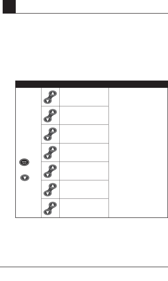
4-22 Rad-87 Pulse CO-Oximeter Operator’s Manual
4operation
SETUP MENU LEVEL 3
ENTER BUTTON + DOWN BUTTON MENU SETTINGS
The Level 3 menu contains advanced parameter/measurement settings.
To access Level 3 parameters/measurements, hold down the Enter Button and press the Down
Button for 5 seconds. After entering menu Level 3, use the Enter Button to save new settings and
move to the next menu.
The user may cycle through the menu options by continuing to press the Enter Button. Pressing
the Display Button will exit the menu and return the display to home display screen.
AVERAGING TIME
BUTTONS SETTINGS
Hold down
the Enter
Button and
press the
Down Button
for 5 seconds.
+
Default
8 seconds
Use Up or Down Button to move
between settings
AND
press the Enter Button to accept the
setting and
move to the next menu option.
OR
press the Display Button to exit
without saving the new setting and to
return to the home display screen.
4 seconds
2 seconds
16 seconds
14 seconds
12 seconds
10 seconds
(The cycling function for the
menu options is not available.)
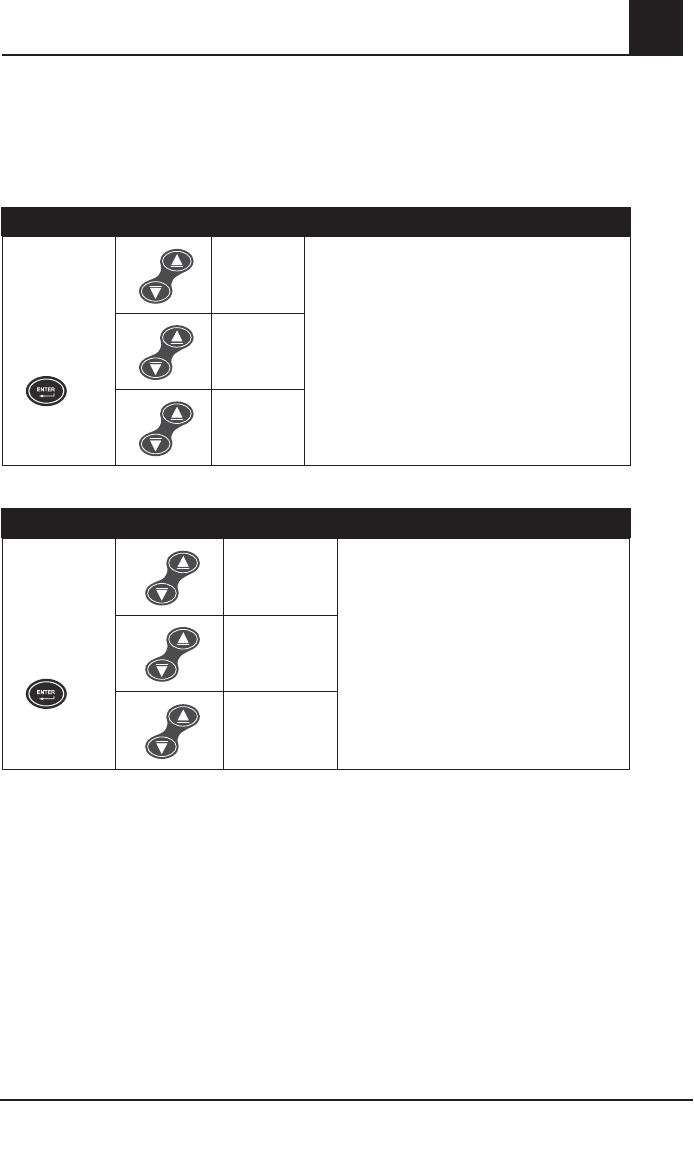
Rad-87 Pulse CO-Oximeter Operator’s Manual 4-23
4
operation
SETUP MENU LEVEL 3 (CONTINUED)
RAPID DESAT LIMIT
The Rapid Desat Limit is designed to detect rapid desaturations of 5% or 10% below the low
alarm limit and overrides the Alarm Delay feature when activated.
BUTTONS SETTING
Press the Enter
Button again
to move to the
next menu.
Default
5%
Use Up or Down Button to move between settings
AND
press the Enter Button to accept the setting and
move to the next menu.
OR
press the Display Button to exit without saving the
new settings and to return to the home display
screen.
Off
10%
ALARM ON/OFF
BUTTONS SETTING
Press the Enter
Button again
to move to the
next menu.
Default
On
Use Up or Down Button to move between
settings
AND
press the Enter Button to accept the setting
and move to the next menu.
OR
press the Display Button to exit without saving
the new setting and to return to the home
display screen.
Off
Off rE
(Alarm off with
reminder.)
*When Alarm On/Off is set to "Off rE", the audible alarm "beeps" twice every three minutes to
remind the user that the Rad-87 is currently in alarm status but the audible alarm is muted.
Visual alarms are active in this mode. If an alarm limit is violated, the associated parameter/
measurement label and value flash, the alarm bell flashes red for high priority alarms and the
System Status Light is solid yellow for low priority alarms, flashes yellow for medium priority
alarms or flashes red for high priority alarms.
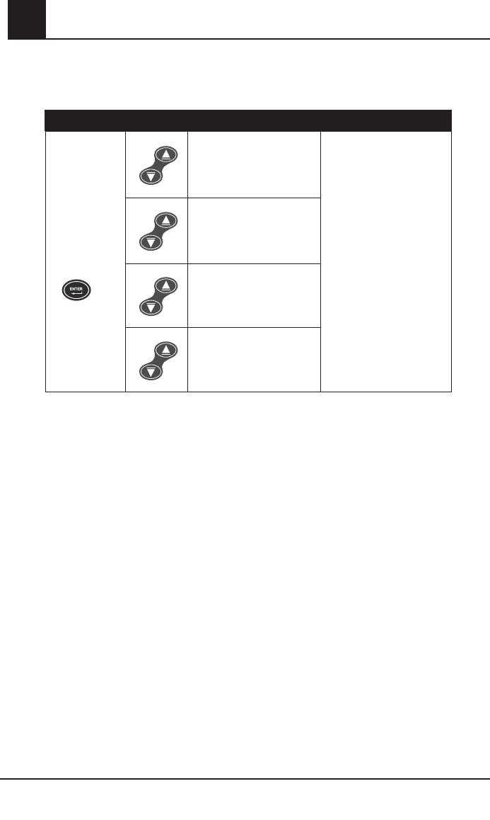
4-24 Rad-87 Pulse CO-Oximeter Operator’s Manual
4operation
SETUP MENU LEVEL 3 (CONTINUED)
DEFAULT SETTINGS
BUTTONS SETTING
Press the Enter
Button again
to move to the
next menu.
No change
(Do not adjust factory
default settings.) Use Up or Down Button to
move between settings
AND
press the Enter Button
to accept the setting and
move to the next menu.
OR
press the Display Button to
exit without saving the new
setting and to return to the
home display screen.
User Default
(Set to user settings.*)
Factory Default
(Restore factory default
settings.)
Set Device Profile
(One or more pre-defined
device profiles)
*Set the Factory Default to this setting when confi guring a Device Profi le. Refer to the Device
Profi le Setup and Use section of this chapter for additional information and instructions.

Rad-87 Pulse CO-Oximeter Operator’s Manual 4-25
4
operation
Device Profile Setup and Use
The Rad-87 can be configured to save changes to the device settings as a Device Profile. Using
the Rad-87 button menu or an external configuration application, users can adjust Rad-87 settings
and parameter/measurement alarm limits. After changing settings, the user may save the settings
as a Device Profile. This Device Profile becomes the new default settings and the saved (Device
Profile) settings will be retained after a power cycle.
To save the settings as a profile from the Rad-87 button menu, the user must enter Setup Menu
Level 3 by pressing and holding the Enter Button and Down Button at the same time for 5
seconds. Then, by pressing the Enter Button three times, the Default Settings screen is displayed.
Press the Up or Down Arrow Button until “User Default – Set” is displayed on the LCD. The user
can press the Enter Button again to save the settings.
Using an external configuration application, the user can save up to five profiles. The user may
select a color for the Device Profile LED to associate with the saved profiles. The Device Profile
LED (located on the front panel of the Rad-87 above the sensor connector) will illuminate with
the selected color, allowing the user to verify at a glance that a Device Profile has been set on
the Rad-87. If changes are made to the device settings after the Device Profile feature has been
enabled, the Device Profile LED will turn off until the device is returned to the user configured
default settings or powered off, indicating a change from the Device Profile settings.
To set a device profile, the user enters Menu Level 3 by pressing and holding the Enter Button
and Down Arrow Button at the same time for 5 seconds. Then, by pressing the Enter Button three
times, the Default Setting screen is displayed. The user can use the Up or Down Arrow Button to
select the desired profile and press the Enter Button to save the setting.
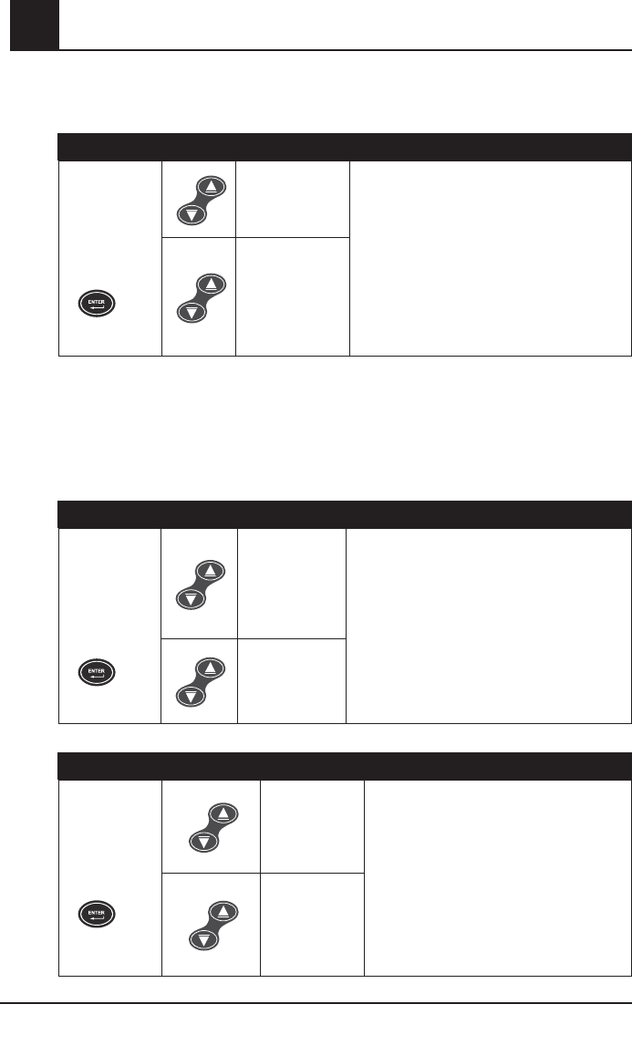
4-26 Rad-87 Pulse CO-Oximeter Operator’s Manual
4operation
SETUP MENU LEVEL 3 (CONTINUED)
PVI BAR ON/OFF (IF AVAILABLE)
BUTTONS SETTING
Press the Enter
Button again
to move to the
next menu.
Default
On
Use Up or Down Button to move between settings
AND
press the Enter Button to accept the setting and
move to the next menu.
OR
press the Display Button to exit without saving
the new setting and to return to the home display
screen.
Off
(No PVI Bar
or parameter/
measurement
label displayed)
SMART TONE ON/OFF
The SmartTone feature uses a proprietary algorithm that will provide pulse tones during excessive
motion and low perfusion conditions. The pulse tone is based on an averaged pulse rate measurement
from the proprietary algorithm and may not identify irregular heart beat patterns when there is excessive
artifact present. The Normal Tone feature uses a proprietary algorithm that will provide pulse tones during
non motion and adequate perfusion conditions. In this mode, the pulse tone may not sound if excessive
artifact is present.
BUTTONS SETTING
Press the
Enter Button
again to move
to the next
menu.
Default
Off
(Normal Tone)
Use Up or Down Button to move between settings
AND
press the Enter Button to accept the setting and
move to the next menu.
OR
press the Display Button to exit without saving
the new setting and to return to the home display
screen.
On
(Smart Tone)
YEAR
BUTTONS SETTING
Press the Enter
Button again
to move to the
next menu.
Default
year
Use Up or Down Button to move between settings
AND
press the Enter Button to accept the setting and
move to the next menu.
OR
press the Display Button to exit without saving
the new setting and to return to the home display
screen.
Use Up or Down
Button to adjust
the setting.
Rad-87 Pulse CO-Oximeter Operator’s Manual 4-27
4
operation
SETUP MENU LEVEL 3 (CONTINUED)
MONTH
BUTTONS SETTING
Press the Enter
Button again
to move to the
next menu
Default
Month
Use Up or Down Button to move between
settings
AND
press the Enter Button to accept the setting
and move to the next menu.
OR
press the Display Button to exit without
saving the new setting and to return to the
home display screen.
Use Up or
Down Button
to adjust the
setting.
DAY
BUTTONS SETTING
Press the Enter
Button again
to move to the
next menu.
Default
days
Use Up or Down Button to move between
settings
AND
press the Enter Button to accept the setting
and move to the next menu.
OR
press the Display Button to exit without
saving the new setting and to return to the
home display screen.
Use Up or
Down Button
to adjust the
setting.
HOUR
BUTTONS SETTING
Press the Enter
Button again
to move to the
next menu.
Default
hour
Use Up or Down Button to move between
settings
AND
press the Enter Button to accept the setting
and move to the next menu.
OR
press the Display Button to exit without
saving the new setting and to return to the
home display screen.
Use Up or
Down Button
to adjust the
setting.
4-28 Rad-87 Pulse CO-Oximeter Operator’s Manual
4operation
SETUP MENU LEVEL 3 (CONTINUED)
MINUTE
BUTTONS SETTING
Press the Enter
Button again
to move to the
next menu.
Default
30 minutes
Use Up or Down Button to move between
settings
AND
press the Enter Button to accept the setting
and move to the next menu.
OR
press the Display Button to exit without saving
the new setting and to return to the home
display screen.
Use Up or
Down Button
to adjust the
setting.
SOFTWARE VERSION
BUTTONS SETTING
Press the Enter Button
again to move to the
next menu
Displays software version.
SERIAL OUTPUT
BUTTONS SETTING
Press the Enter
Button again to
move to the next
menu.
Default
AS2 (ASCII 2)
Use Up or Down Button to move between
settings
AND
press the Enter Button to accept the
setting and move to the next menu.
OR
press the Display Button to exit without
saving the new setting and to return to the
home display screen.
AS1 (ASCII 1)
PHL
(Philips Vuelink)

Rad-87 Pulse CO-Oximeter Operator’s Manual 4-29
4
operation
SETUP MENU LEVEL 3 (CONTINUED)
INTERFACE ALARMS
When Rad-87 is interfaced to another system and the Interface Alarms are set to "Off", SpO2 and
BPM audible alarms are muted at the Rad-87 and active at the interfaced system. This prevents
both systems from producing SpO2 and BPM audible alarms at the same time.
NOTE: The Rad-87 reverts to Interface Alarms "On" during power interruptions or when the
interface connection is lost. This ensures that the Rad-87 provides SpO2 and BPM audible
alarms when connection to the interfaced system becomes compromised.
BUTTONS SETTING
Press the Enter
Button again to
move to the next
menu.
Default
On
NOTE: LCD shows
SpO2 and BPM alarms
On.
Use Up or Down Button to move
between settings
AND
press the Enter Button to accept the
setting and
move to the next menu.
OR
press the Display Button to exit
without saving the new setting and to
return to the home display screen.
Off (only SpO2/BPM)
NOTE: LCD shows
SpO2 and BPM alarms
Off.
System interfaces
PHILIPS VUELINK SETUP
1. Select the Philips VueLink selection from the Serial Output menu on the Rad-87. After
selecting, choose the preferred settings by stepping through menu options.
2. Connect one end of the VueLink cable to the Serial Output connector on the back of the
Rad-87.
3. Connect the other end of the VueLink cable to the VueLink module and insert the module into
the Philips/Agilent monitor rack.
4. The SpO2 and pulse rate values will automatically appear on the HP/Agilent monitor.
5. In order for the pleth waveform to be displayed on the Philips/Agilent monitor and for the Philips/
Agilent monitor to indicate the alarm conditions measured by the pulse oximeter, the user must
configure the Philips/Agilent monitor. Please see the Philips/Agilent Operator’s manual for complete
instructions.
6. The Rad-87 Pulse CO-Oximeter can be set up to audibly indicate all patient alarms while
communicating with the Philips/ VueLink module. Use the Interface Alarms setting in the Output
menu to enable and disable audible alarms on the Rad-87.

4-30 Rad-87 Pulse CO-Oximeter Operator’s Manual
4operation
SETUP MENU LEVEL 3 (CONTINUED)
RADNET SETUP
1. Connect one end of the serial cable to the Serial Output connector on the back of the
Rad-87.
2. Connect the other end of the serial cable to the RadNet Interface Module connector.
3. Turn the RadNet Interface Module on.
4. Select the ASCII 2 selection from the Serial options on the Rad-87.
5. A proper connection is shown by the RadNet Interface Module's Online LED being solid.
6. With a properly configured RadNet Interface Module, the Rad-87 will automatically display
the SpO2, PVI, PI and Pulse Rate parameters/measurements on the screen at the RadNet
Central Station.
7. The Rad-87 Pulse CO-Oximeter can be set up to audibly indicate all patient alarms while
communicating with the RadNet Interface module.
PATIENT SAFETYNET SETUP
1. Select the ASCII 2 selection from the Serial options on the Rad-87.
2. Contact Masimo installation personnel for proper installation guidance.
Rad-87 Pulse CO-Oximeter Operator’s Manual 4-31
4
operation
SETUP MENU LEVEL 3 (CONTINUED)
NURSE CALL*
BUTTONS SETTING
Press the Enter
Button again
to move to
the next menu
option.
Default
Alarm
Use Up or Down Button to move between
settings
AND
press the Enter Button to accept the setting
and move to the next menu option.
OR
press the Display Button to exit without saving
the new setting and to return to the home
display screen.
Signal IQ
Alarm and
Signal IQ
*Refer to Section 7, Nurse call specifi cations for additional information.
POLARITY*
BUTTONS SETTING
Press the Enter
Button again
to move to
the next menu
option.
Default
Normal
Use Up or Down Button to move between
settings
AND
press the Enter Button to accept the setting
and move to the next menu option.
OR
press the Display Button to exit without saving
the new setting and to return to the home
display screen.
Inverse
*Refer to Section 7, Nurse call specifi cations for additional information.
LINE FREQUENCY
BUTTONS SETTING
Press the Enter
Button again
to move to
the next menu
option.
Default
60
Use Up or Down Button to move between
settings
AND
press the Enter Button to accept the setting
and move to the next menu option.
OR
press the Display Button to exit without saving
the new setting and to return to the home
display screen.
50
4-32 Rad-87 Pulse CO-Oximeter Operator’s Manual
4
SETUP MENU LEVEL 3 (CONTINUED)
PARAMETER/MEASUREMENT SELECT - SCREEN 1
BUTTONS SETTING
Press the Enter
Button again
to move to
the next menu
option.
SpHb
(if available)
Use Up or Down Button to move between
settings
AND
press the Enter Button to accept the setting and
move to the next menu option.
OR
press the Display Button to exit without saving
the new setting and to return to the home
display screen.
PVI
(if available)
(no parameter/
measurement
displayed)
PARAMETER/MEASUREMENT SELECT - SCREEN 2
BUTTONS SETTING
Press the Enter
Button again
to move to
the next menu
option.
SpHb
(if available)
Use Up or Down Button to move between
settings
AND
press the Enter Button to accept the setting
and move to the next menu option.
OR
press the Display Button to exit without saving
the new setting and to return to the home
display screen.
PVI
(if available)
(no parameter/
measurement
displayed)
operation
Rad-87 Pulse CO-Oximeter Operator’s Manual 4-33
4
SETUP MENU LEVEL 3 (CONTINUED)
PARAMETER/MEASUREMENT SELECT - SCREEN 3
BUTTONS SETTING
Press the Enter
Button again
to move to
the next menu
option.
SpHb
(if available)
Use Up or Down Button to move between
settings
AND
press the Enter Button to accept the setting
and move to the next menu option.
OR
press the Display Button to exit without saving
the new setting and to return to the home
display screen.
PVI
(if available)
(no parameter/
measurement
displayed)
LCD LANGUAGE
BUTTONS SETTING
Press the Enter
Button again
to move to
the next menu
option.
Default
English
Use Up or Down Button to move between
settings
AND
press the Enter Button to accept the setting
and move to the next menu option.
OR
press the Display Button to exit without saving
the new setting and to return to the home
display screen.
Scrolls through
available
languages
displayed on
the LCD
ENTER BUTTON + UP BUTTON MENU SETTING
SET MODE
BUTTONS SETTING
Hold down the
Enter Button
and press the
Up Button for 5
seconds.
+
Default
Standard
Use Up or Down Button to move between
settings
AND
press the Enter Button to accept the setting.
OR
press the Display Button to exit without saving
the new setting and to return to the home
display screen.
Sleep Mode*
Home Mode
*CAUTION: ALARMS ARE DISABLED IN THIS MODE.
operation

4-34 Rad-87 Pulse CO-Oximeter Operator’s Manual
4
HOME MODE OPERATION
The Rad-87 can be placed into the Home Mode to protect unqualified users from changing the Rad-87
alarm settings and operation. Only the following menu and front panel functions are available: display
brightness, pulse beep volume adjustment and alarm silence. Alarm volume is at highest setting. All
default and user defined default settings are locked to their current values when home mode is selected
and return to those values after a power cycle. Upon power up, the Hnn mode will be displayed along
with a 10 second display of parameters/measurements. To turn the device off the Power Button must be
depressed and held for 3 seconds. The Enter and Up Buttons held simultaneously for 5 second will put it
back into the special menu to select a different mode.
SLEEP MODE OPERATION
The Rad-87 can be placed into the Sleep Mode to allow the device to capture normal and abnormal
patient data without triggering the alarms. This mode will blank out the LED and the LCD Displays with
the exception of the AC Power Indicator, the System Status Light, and the Battery Level Indicator and
disables the alarms even after a power cycle. However, pressing any button illuminates the display and
the System Status Light (solid yellow) for 10 seconds. Upon power up, the SLP mode will be displayed
along with a 10 second display of parameterr/measurement settings. The Enter and Up Buttons held
simultaneously for 5 seconds will put it back into the special menu to select a different mode.
CAUTION: ALARMS ARE DISABLED IN THIS MODE
BRIGHTNESS BUTTON + DOWN BUTTON MENU SETTING
Access the Enable/Disable Radio menu by holding down the Brightness Button and the Down
Button for 5 seconds.
ENABLE/DISABLE RADIO
BUTTONS SETTING
Hold down the
Brightness Button
and press the Down
Button for 5 seconds.
+
Default
Off
Use Up or Down Button to move between
settings
AND
press the Enter Button to accept the setting
and exit to the home display screen.
On
LCD DISPLAY FUNCTION WITH RADIO CONFIGURED AND ENABLED
When the Radio feature is enabled (set to "On") and configured with the required network
information, the LCD Display shows the following information for 20 seconds:
■ SSID
■ IP address
■ Subnet
■ Gateway
■ MAC Address
operation

